elevator technology h200 product catalogue...elevator technology mastering german engineering and...
TRANSCRIPT

02 Product Summary
06 Cabin
22 Door
32 Shaft structure
34 Feasibility Information
47 Communication & drive
48 FAQ
52 Features & Benefits
ContactSample Company Name Samplestreet 12 12345 Samplecity, Samplecountry P: +49 123 456 - 0 F: +49 123 456 - 078 www.samplewebsite.com
H200 Product CatalogueElevator Technology
Mastering Germanengineering and Italian design
The H200 hydraulic home lift fits everywhere
The H200 incorporates proven and reliable technology.The hydraulic drive system can offer a wide range of choices, from a minimal layout to a fully enclosed cabin without compromises in comfort and performances.
Wide choice of materials and finishes.Trust our designer's choice for stylish combinations or feel free to choose more conventional solutions. The H200 can be customised in many details and countless sizes, perfectly matching your environment.

H200 | Product Summary 2
Technical complianceEuropean Machine directive 2006/42/ECReference standard: EN 81-41
Drive systemHydraulic control unit with indirect action by chains
Max speedEurope: 0,15 m/s according to 2006/42/ECSoft start / stop
Rated Load 250 - 450 kg depending on cabin size
Travel height900 - 13100 mm(up to 15100 for light configurations)
Distance bewteenintermediate floors
min. 250 mm (doors at dfferent sides)With standard doors, net height 2000 mmmin. 2200 (masonry shaft doors same side)min. 2400 (metallic shaft doors same side)
Number of stops Max. 6 stops per lift / 12 doors per lift
Number of doors per floor Max. 2 doors per floor
Pit120 mm (no pit is required when there is a threshold/ramp)
Shaft Top heightStandard 2300 mm depending on shaft type and landing doors.
Cabin control Hold-to-Run
Landing control (on door) One-touch
EnvironmentIndoor / Outdoor (between -5°C and +40°C with oil heating device).
Emergency lowering Battery operated emergency lowering
Control voltage 24V
Power requirements 1-phase 230Vac 50/60Hz - Max Power 3 kW
Circuit Breaker / RCD 16A Tripping curves C / 30mA class A or B
Cabinet for Hydraulic unit and Electrical panel
Dimensions: 750x1500x460 mm RAL 7001; Optionally painted at choice.
H200 Hold To Run - fact sheetThe H200 incorporates proven and reliable hydraulic technology specifically designed to offer comfort and performance in private and public applications.A safe and efficient Home lift with speed up to 0,15 m/s certified according to the Machine Directive.
The lift has a compact open cabin to fit in the narrowest environments or a Panel wall with ceiling for a completely panoramic installation.
Platform with ceiling and Swing doors at landings
Cabin without doors and Swing doors at landings

H200 | Product Summary 3
Cabin DimensionsH200 is available in 100 different plan sizes
H200 is also offered in customised dimensions
The rated load depends on the platform size and the required power supply is 230 V 1-phase.
Plan CodeNominal Cabin
Dimensions (mm)Nominal
Floor area (m2)Nominal Load (kg)
P1 900 x 1200 1,08 270
P2 1000 x 800 0,80 250
P3 1000 x 1000 1,00 250
P4 1200 x 1000 1,20 300
P5 1200 x 1200 1,44 360
P6 1400 x 900 1,26 315
P7 1400 x 1000 1,40 350
P8 1400 x 1100 1,54 400
H200 Hold To Run - dimensions and configurations
Our Home lift H200 can be offered with standard preconfigured solutions or can be customised in every detail and dimension perfectly matching your environment.• Panel wall with ceiling or Cabin without doors• Access side(s) monitored by photocells. Optional full height light curtains
for the cabin accesses• Application in existing shaft or with its own metallic shaft• Indoor or Outdoor• Front, Lateral, Opposite and Adjacent accesses
Predefined plan sizes - cabin dimensionsThe most frequently requested plan sizes. Rated load according to EN81-41 (250 kg/m2) up to 400 kg maximum, depending on cabin type, access configuration and optional features.
Cabins with intermediate dimensions are available.Please refer to “Feasibility Information” section.

H200 | Product Summary 4
Technical complianceEuropean Machine directive 2006/42/ECReference standard: EN 81-41
Drive systemHydraulic control unit with indirect action by chains
Max speedEurope: 0,15 m/s according to 2006/42/EC Soft start / stop
Rated Load 250 - 400 kg depending on cabin size
Travel height900 - 12600 mm(up to 13600 for light configurations)
Distance bewteenintermediate floor
min. 250 mm (doors at dfferent sides)With standard doors, net height 2000 mm min. 2460 (masonry shaft doors same side)min. 2550 (metallic shaft doors same side)
Number of stops Max. 6 stops per lift / 12 doors per lift
Number of doors per floor Max. 2 doors per floor
Pit120 mm (no pit is required when there is a threshold/ramp)
Shaft Top heightFolding Doors. Std 2320 mm (Reduced 2240)Sliding Doors: Photocells 2450 mm / Light Curtains 2500 mm)
Cabin control One-touch
Landing control (on door) One-touch with call reservation
EnvironmentIndoor / Outdoor (between -5°C and +40°C with oil heating device).
Emergency lowering Battery operated emergency lowering
Control voltage 24V
Power requirements 1-phase 230Vac 50/60Hz - Max Power 3 kW
Circuit Breaker / RCD 16A Tripping curves C / 30mA class A or B
Cabinet for Hydraulic unit and Electrical panel
Dimensions: 750x1500x460 mm RAL 7001; Optionally painted at choice.
H200 Automatic - fact sheet
The H200 incorporates proven and reliable hydraulic technology and can offer comfort and performance. A safe and efficient Home lift for superior performances with speed from 0,15 m/s and a fully automatic operation when provided with cabin doors
The lift has a completely enclosed cabin for a comfortable automatic operation.
Cabin with Folding Doors and Swing doors at landings
Cabin with Sliding doors and Sliding doors at landings

H200 | Product Summary 5
Cabin DimensionsH200 is available in more than 200 different plan sizes
H200 is also offered in customised dimensions
The rated load depends on the platform size and the required power supply is 230 V 1-phase.
Plan CodeNominal Cabin
Dimensions (mm)Nominal
Floor area (m2)Nominal Load (kg)
P1 900 x 1200 1,08 270
P2 1000 x 800 0,80 250
P3 1000 x 1000 1,00 250
P4 1200 x 1000 1,20 300
P5 1200 x 1200 1,44 360
P6 1400 x 900 1,26 315
P7 1400 x 1000 1,40 350
P8 1400 x 1100 1,54 400
H200 Automatic - dimensions and configurations
Our Home lift H200 can be offered with standard preconfigured solutions or can be customised in every detail and dimension perfectly matching your environment.• Cabin with automatic Folding Doors• Cabin with automatic Sliding Doors• Application in existing shaft or with its own metallic shaft• Indoor or Outdoor• Front, Lateral, Opposite and Adjacent accesses
Predefined plan sizes - cabin dimensionsThe most frequently requested plan sizes. Rated load according to EN81-41 (250 kg/m2) up to 400 kg maximum, depending on cabin type, access configuration and optional features.
Cabins with intermediate dimensions are available.Please refer to “Feasibility Information” section.

Nominal Dimensions
H200 full panel with ceiling is available in more than 50 plan sizes.Platform dimension has been preselected according to the most frequently asked configurations and the layout is designed to maximize the net door access.Detailed drawings are included in the annex.
Intermediate dimensions for doors and plan sizes are possible.Smallest Cabin (CWxCD): 560 mm x 600 mm with access side A and/or CSmallest Cabin (CWxCD): 630 mm x 600 mm with access side BBiggest Cabin (CWxCD): 1600 mm x 1100 mm
H200 | Cabin 6
H200 full panel with ceilingFull Panel with ceiling
H200 is delivered with a C-shaped platform made of a platform, a full height panel (2100 mm) with a roof.The panels and the roof can be:• Skinplate or RAL painted• made in Stainless Steel
The full height panel is available for G-side in different sizes and is complemented with the vertical posts containing a set of photocells for each open side.
Panel heightStandard 2100 mm. For more details and information about minimum free height please refer to pag.40
Fold down seatIn solid transparent plexiglass and with metal like paintedbrackets. The seat has to be folded back manually after use.
Can be ordered as an option.Size: 300 x 420 mmRated Load: 100 kg according to EN81-41
PlatformProvided with vinyl floor at choice
Control Panel & Handrail Control Panel is black mirror, comes with white LED backlight and can be fitted with TFT display and autodialer. A handrail is mandatory according to EN81-41 and is delivered as standard in black finish 60 cm wide.
Full Panel Platform with CeilingHold to Run operationRed Button for emergency situation in the COP
CW
CD
H200 cabin without doors
H200 | Cabin 7
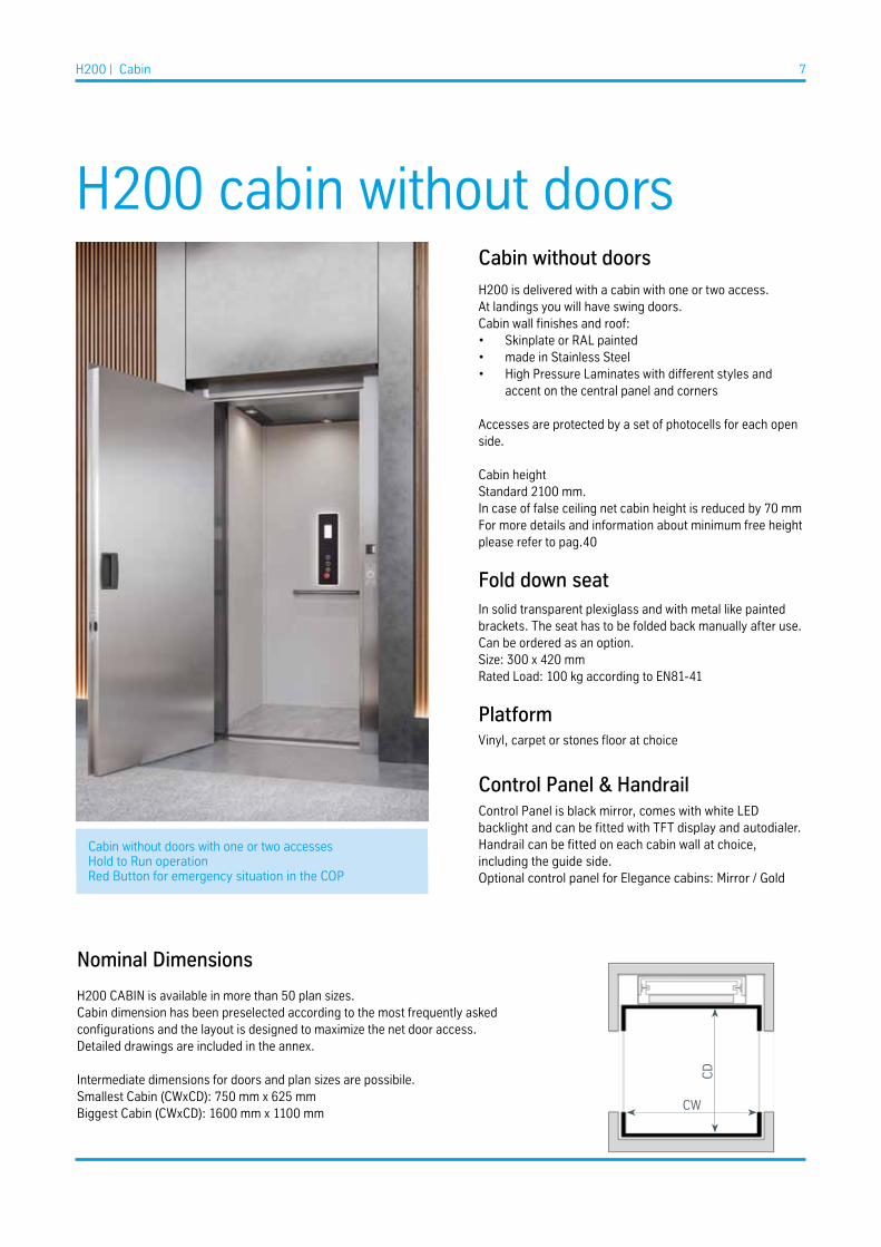
Cabin without doors
H200 is delivered with a cabin with one or two access.At landings you will have swing doors.Cabin wall finishes and roof:• Skinplate or RAL painted• made in Stainless Steel• High Pressure Laminates with different styles and
accent on the central panel and corners
Accesses are protected by a set of photocells for each open side.
Cabin heightStandard 2100 mm.In case of false ceiling net cabin height is reduced by 70 mmFor more details and information about minimum free height please refer to pag.40
Fold down seatIn solid transparent plexiglass and with metal like paintedbrackets. The seat has to be folded back manually after use.Can be ordered as an option.Size: 300 x 420 mmRated Load: 100 kg according to EN81-41
PlatformVinyl, carpet or stones floor at choice
Control Panel & Handrail Control Panel is black mirror, comes with white LED backlight and can be fitted with TFT display and autodialer. Handrail can be fitted on each cabin wall at choice, including the guide side.Optional control panel for Elegance cabins: Mirror / Gold
Cabin without doors with one or two accessesHold to Run operationRed Button for emergency situation in the COP
Nominal Dimensions
H200 CABIN is available in more than 50 plan sizes.Cabin dimension has been preselected according to the most frequently asked configurations and the layout is designed to maximize the net door access.Detailed drawings are included in the annex.
Intermediate dimensions for doors and plan sizes are possibile.Smallest Cabin (CWxCD): 750 mm x 625 mmBiggest Cabin (CWxCD): 1600 mm x 1100 mm
CW
CD

H200 | Cabin 8
H200 cabin with folding doorsCabin folding doorsH200 is delivered with a completely enclosed cabin with automatic folding doors at each access (max 2).Folding foors are a perfect fit in case of space claim.At landings you will have swing doors.
Cabin doors:• 4 panels central opening• RAL painted or Stainless Steel• Blind or Panoramic
Cabin wall finishes:• Skinplate or RAL painted• Stainless Steel• High Pressure Laminates with different syles and accent
on the central panel and corners
Cabin heightStandard 2100 mmIn case of false ceiling net cabin height is reduced by 70 mm.For more details and information about minimum free height please refer to pag.40
Control Panel & Handrail Control Panel is black mirror, comes with white LED backlight and can be fitted with TFT display and autodialer. Handrail can be fitted on each cabin wall at choice, including the guide side.
Optional control panel for Elegance cabins: Mirror / Gold
Cabin with folding doors
Nominal Dimensions
H200 with folding doors is available in more than 50 plan sizes.Cabin dimension has been preselected according to the most frequently asked configurations and the layout is designed to maximize the net door access.Detailed drawings are included in the annex.
Intermediate dimensions for doors and plan sizes are possible.Smallest Cabin (CWxCD): 750 mm x 650 mmBiggest Cabin (CWxCD): 1400 mm x 1100 mm
CWCW/CD: Cabin dimensions measured wall to wall - recommended for public accessCWd/CDd: Cabin dimensions measured door to door - valuable for privateRated Load based on CWxCD
CWd CD
=CD
d
Nominal Dimensions
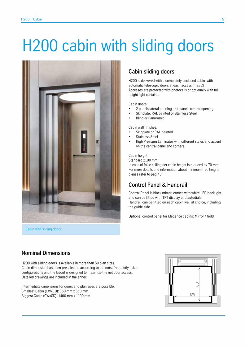
H200 with sliding doors is available in more than 50 plan sizes.Cabin dimension has been preselected according to the most frequently asked configurations and the layout is designed to maximize the net door access.Detailed drawings are included in the annex.
Intermediate dimensions for doors and plan sizes are possible.Smallest Cabin (CWxCD): 750 mm x 650 mmBiggest Cabin (CWxCD): 1400 mm x 1100 mm
H200 cabin with sliding doorsCabin sliding doors
H200 is delivered with a completely enclosed cabin with automatic telescopic doors at each access (max 2)Accesses are protected with photocells or optionally with full height light curtains.
Cabin doors:• 2 panels lateral opening or 4 panels central opening• Skinplate, RAL painted or Stainless Steel• Blind or Panoramic
Cabin wall finishes:• Skinplate or RAL painted• Stainless Steel• High Pressure Laminates with different styles and accent
on the central panel and corners
Cabin heightStandard 2100 mmIn case of false ceiling net cabin height is reduced by 70 mm.For more details and information about minimum free height please refer to pag.40
Control Panel & Handrail Control Panel is black mirror, comes with white LED backlight and can be fitted with TFT display and autodialer. Handrail can be fitted on each cabin wall at choice, including the guide side.
Optional control panel for Elegance cabins: Mirror / Gold
Cabin with sliding doors
CW
CD
H200 | Cabin 9

H200 | Cabin 10
Cabin - Main features
Control Operation PanelThe control panel is always placed on the machine side (G-side) of the cabin. It contains the destination buttons, the alarm button, the open door button or the emergency red button depending on the models. As an option it can be configured with a colour display and an autodialer system and/or a key.It has a backlight all around the profile which emphasizes the design of the panel.
Standard: Polished Steel Black.Optional: Mirror; Gold (Elegance Cabin only)
The location of the platform buttons and the handrail conform to EN 81-41
Destination buttonsDestination buttons conform to EN 81-41. The location of the buttons are within the limits in the standard, i.e. height between cabin floor and the centre line of the buttons is between 900-1100 mm.
Standard buttons are engraved with braille.Diameter of buttons in vertical panel: 37 mmFollowing buttons are available: -2, -1, 0, 1, 2, 3, 4, 5, 6, B, BG, BV, G, K, KV, P, U, E.
COP layout is in two columns, in case of more buttons.Finishes matching with the control panel.
Alarm buttonA standard alarm button is always delivered with the lift. The alarm button is connected to an external alarm sounder and to an optional autodialer.
When it is pressed, a siren sounds.Keep it pressed for 3 seconds to activate the emergency call with the optional autodialer.
Handrail A handrail is mandatory according to EN81-41
The height between platform floor and top edge of the handrail is between 875 - 925 mm.Minimum cross-sectional dimension is 30 mm.
Standard Cabin: Black [G-side only] or Stainless SteelElegance Cabin: Stainless steel or Gold (Satin).
1
1
2
3
4
2 3
4

External alarm sounder The alarm sounder is mounted in the electrical cabinet.It is connected to the alarm button and when the button is pressed the siren will give a loud signal outside the lift to attract attention in case of emergency.
Display and Landing indicatorTFT colour display is positioned on the control panel. It shows which floor the lift is on at the moment.
Display can also show the following information from the system: • Direction of the lift when travelling• Several different icons depending on the message or the status of the lift (for instance, a bell when the alarm button has been pressed, a weight symbol if the lift is overloaded)• Error code for diagnostics• If connected to the building's fire alarm a symbol will be shown when alarm is activated.
The display can be ordered as an option and different audiooptions can be selected:• No acoustic signal• Acoustic signal in the cabin and at landings• Voice announcer at cabin and acoustic signal at landings
Available languages for the voice announcer are: English,Italian, French, German, Spanish, Dutch, Portuguese, Czech and Russian.
Building Integration In combination with the Display, the lift can be connected to the building's fire alarm. In case of fire, a symbol on the display will be shown when the alarm is activated and the lift will move to a predetermined floor and park there.
Key switch on platformThe key switch locks the Home lift's functions and prohibits unauthorized use.
Two options to choose from:• mechanical key• i-button
One key switch per cabin or one key switch per each stop (max 4) can be provided. Specific configurations can be designed to allow individual access for different users.
H200 | Cabin 11
5
7
6
8
5
6
7
Mechanical key i-button
8

H200 | Cabin 12
Full Panel with ceiling - Layout
Ceiling:• Three LED spots• Same finish as cabin walls
Access Side:• Photocells
Flooring:• At choice from our catalogue (1)• Supplied without vinyl (2)
1
2
H200 | Cabin 13
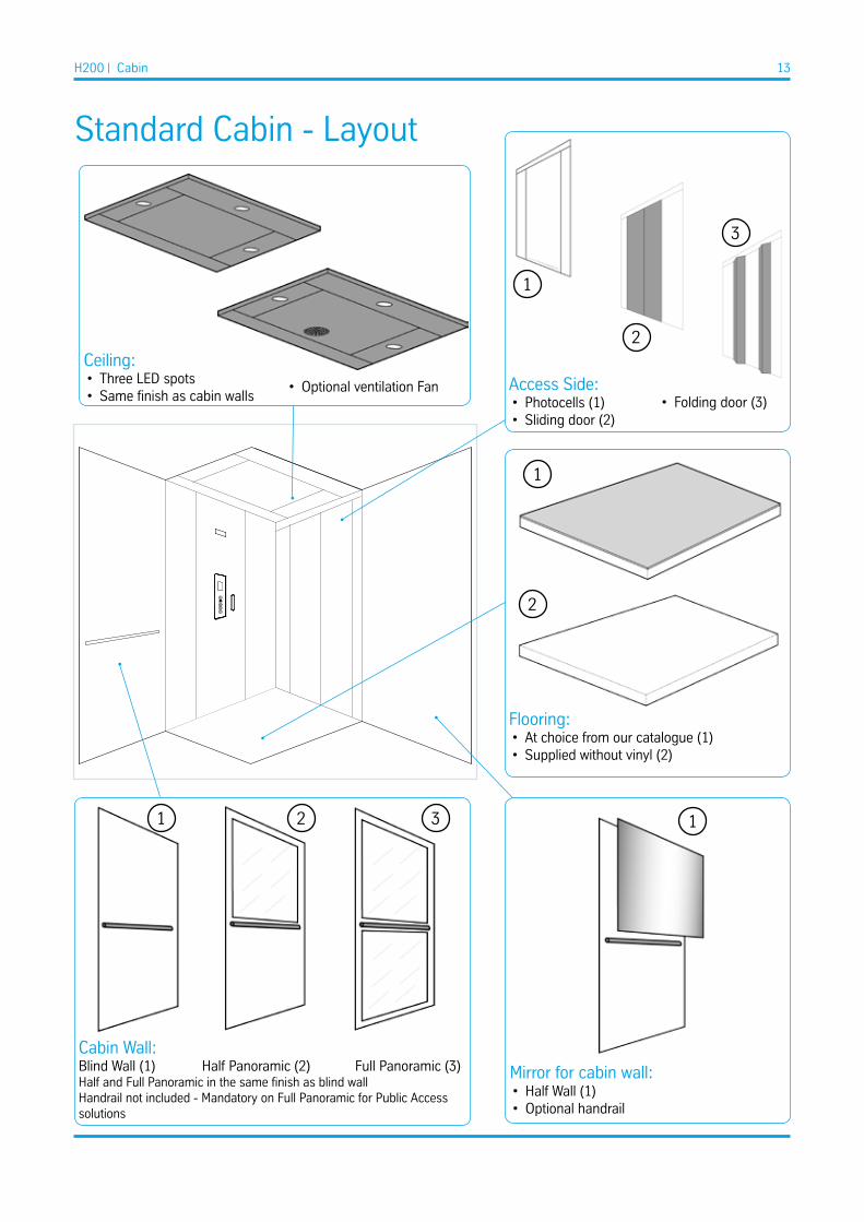
Standard Cabin - Layout
Ceiling:• Three LED spots• Same finish as cabin walls
Access Side:• Photocells (1)• Sliding door (2)
Cabin Wall:Blind Wall (1) Half Panoramic (2) Full Panoramic (3)Half and Full Panoramic in the same finish as blind wallHandrail not included - Mandatory on Full Panoramic for Public Access solutions
Flooring:• At choice from our catalogue (1)• Supplied without vinyl (2)
1
1
2
2 3
2
3
• Folding door (3)
Mirror for cabin wall:
1
• Half Wall (1)• Optional handrail
• Optional ventilation Fan
1

H200 | Cabin 14
Elegance Cabin - Layout
Suspendended ceiling:• Opal (1)• Round (2)
Flooring:• At choice from our catalogue (1)• Prepared for Customer application (2)
1
2
Mirror for cabin wall:
2 3
• Half wall (2)• Full wall (3)
1
3
2
4
• Plain steel (3)• Starry sky - Stainless Steel (4)
1 2 3 1
• Slat vertical - fixed dimensions (1)
Access Side:• Photocells (1)• Sliding door (2)
• Folding door (3)
Cabin Wall:Blind Wall (1) Half Panoramic (2) Full Panoramic (3)Half and Full Panoramic in the same finish as blind wallHandrail not included - Mandatory on Full Panoramic for Public Access solutions
2
3
1

H200 | Cabin 15
Standard Cabin - Finishes
Flooring - FOR BOTH CABIN AND FULL PANEL WITH CEILING
Choose between the following options for safety vinyl flooring with guaranteed life time non-slip.
White Vinyl Sand Vinyl Grey Vinyl
Real colours and layout may differ from those shown. Slight noticeable differences are possible because of different materials. Contents subject to change without notice
Choose to have your lift delivered without flooring, if you want to apply your own. Max 3 mm flooring for flush top alignment.
Cabin WallRAL Colour suggested for painted parts to match with the pre-coated steel.
A4 - RAL9010 (standard)
N1 - RAL7035
PPS1 -RAL 7035
A13 - RAL1013
PPS11 - RAL 1013
A1 - RAL9003
PPS - Metal Like - RAL7037
PPS10 - RAL 9003
B13 - RAL5024
Stainless Steel Satin
G1 - RAL1015
Stainless Steel Linen (Scratch resistant finish)
PRE-COATED STEEL - PLAIN
STAINLESS STEEL
RAL PAINT OF CHOICE - FOR BOTH CABIN AND FULL PANELWITH CEILING
PRE-COATED STEEL - PPS
H200 | Cabin 16
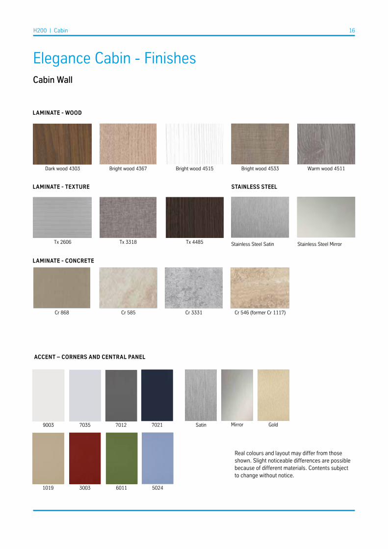
Elegance Cabin - FinishesCabin Wall
Dark wood 4303
Tx 2606
Cr 546 (former Cr 1117)
9003
3003
7035
6011
7021 Mirror7012
50241019
Gold
Warm wood 4511Bright wood 4367
Tx 3318
Cr 868
Bright wood 4515
Tx 4485
Cr 585 Cr 3331
Bright wood 4533
LAmINATE - WOOD
LAmINATE - TExTURE
LAmINATE - CONCRETE
ACCENT – CORNERS AND CENTRAL PANEL
Real colours and layout may differ from those shown. Slight noticeable differences are possible because of different materials. Contents subject to change without notice.
Stainless Steel Satin Stainless Steel Mirror
STAINLESS STEEL
Satin

H200 | Cabin 17
Flooring
Choose between the following options for safety vinyl flooring with guaranteed lifetime non-slip.
Opal (standard)
Plain
Round
Starry Sky
Ceiling
Elegance cabin is always provided with a counterceiling with LED light. Choose between the following options:
White Sand Grey
White
White
Sand
Sand
Grey Black
Grey
STONES
vINyL
CARPETS
1
2
3
4
1
3
2
4Starry sky is stainless steel satin.The other cielings are in RAL9010 (white) painted steel. As option can be ordered in Stainless Steel Satin

H200 | Cabin 18
Modern Europe
Wall: Bright Wood 4515Accent: Black 7021Ceiling: RoundFlooring: Grey VinylMirror: noneHandrail: S.Steel 2 pieces (for 1400 wide cabin only)
Modern AmericasWall: Concrete 3331Accent: Blue 5024Ceiling: PlainFlooring: Grey VinylMirror: Slat verticalHandrail: S.Steel 2 pieces (for 1400 wide cabin only)
Modern AsiaWall: Texture 2606Accent: Red 3003Ceiling: OpalFlooring: Grey VinylMirror: noneHandrail: S.Steel 2 pieces (for 1400 wide cabin only)
1
32
1
2
3
Elegance Cabin - Designer’s choice

H200 | Cabin 19
Classic Europe
Wall: Cool Wood 4511Accent: Beige 1019Ceiling: PlainFlooring: Sand CarpetMirror: Full WallHandrail: S.Steel 2 pieces (for 1400 wide cabin only)
Classic AmericasWall: Texture 3318Accent: Light Grey 7035Ceiling: PlainFlooring: Grey VinylFull Height Panoramic wallHandrail: S.Steel 1 piece onto panoramic wall
Classic AsiaWall: Dark Wood 4303Accent: Red 3003Ceiling: PlainFlooring: Grey VinyMirror: Half Wall Handrail: S.Steel 2 pieces (for 1400 wide cabin only)
1
32
1
2
3

H200 | Cabin 20
Natural Europe
Wall: Warm Wood 4533Accent: Green 6011Ceiling: PlainFlooring: Grey CarpetMirror: noneHandrail: S.Steel 2 pieces (for 1400 wide cabin only)
Natural AmericasWall: Texture 4485Accent: Dark Grey 7012Ceiling: PlainFlooring: Sand CarpetMirror: noneHandrail: S.Steel 2 pieces (for 1400 wide cabin only)
Natural AsiaWall: Bright Wood 4367Accent: Green 6011Ceiling: PlainFlooring: Grey CarpetMirror: noneHandrail: S.Steel 2 pieces (for 1400 wide cabin only)
1
32
1
2
3

H200 | Cabin 21
Modern International
Wall: Texture 868Accent: Steel MirrorCeiling: PlainFlooring: White StoneMirror: noneHandrail: S.Steel 2 pieces (for 1400 wide cabin only)
Natural InternationalWall: Concrete 585Accent: Dark Grey 7012Ceiling: PlainFlooring: White CarpetMirror: noneHandrail: S.Steel 2 pieces (for 1400 wide cabin only)
Classic InternationalWall: Concrete 1117Accent: Steel GoldCeiling: PlainFlooring: Sand StoneMirror: noneHandrail: S.Steel 2 pieces (for 1400 wide cabin only)
1
2
3
1
2
3
Cr 585
Cr 546 (Former Cr 1117)
Dark Grey 7012 Steel Gold

H200 | Doors 22
Sliding doors – Lateral opening
• The door height (HL) is 2000 mm.• The door frames have dimensions 100 mm on each side (M1, M2, HD).• The door sill of the landing door is 90 mm (Cabin door 70 mm).• The frame is 60 mm deep (FD).• The opening can be right or left with two panels.• The lock release has a triangular key provided with each machine.• Standard Installation is fully in the shaft (DHP = 110 mm).
• EI60 and EI120 – Fireproof door can be ordered as option at landings.
Door clear access (PL) Total width (1,5 PL + 145)
600 mm 1045 mm
700 mm 1195 mm
800 mm 1345 mm
900 mm 1495 mm
Nominal dimensions in mm
Sliding doors – Lateral opening – Glass version
• The glass version has the same dimensions as the blind version• The panel dimensions depend on the door clear access as shown in the
picture (PL/N+20) where N is the number of panels• The frame around the glass has standard dimensions and is in Stainless
Steel Satin finish. As option can be painted in RAL colour at choice.• Top and bottom: 120 mm. Lateral: 40 mm and 60 mm
Sample size – lateral open 2 panels - glass version
Door clear access (PL) Panel size Glass Size
600 mm 320 mm 220 mm
700 mm 370 mm 270 mm
800 mm 420 mm 320 mm
900 mm 470 mm 370 mm
Nominal dimensions in mm
Doors

H200 | Doors 23
Sliding doors – Central opening• The door height (HL) is 2000 mm• The door frames have dimensions 100 mm on each side (M1, M2, HD)• The door sill of the landing door is 90 mm (Cabin door 70 mm)• The frame is 60 mm deep (FD)• The opening is central with four panels.• The lock release has a triangular key provided with each machine.• Standard Installation is fully in the shaft (DHP = 110 mm
• EI60 and EI120 – Fireproof door can be ordered as option at landings.
Door clear access (PL) Total width
600 mm 1040 mm
700 mm 1165 mm
800 mm 1300 mm
900 mm 1450 mm
PL 600 650 700 ≥750
G 40 30 15 0
Nominal dimensions in mm

H200 | Doors 24
Cabin folding doors
• Four panel central opening.• The door height is 2000 mm. • The door sill of the landing door is 100 mm
Door clear access [DA] A
600 mm 90 mm
700 mm 115 mm
800 mm 140 mm
900 mm 165 mm
“A” is the max encumbrance in the cabin with door opened
Nominal dimensions in millimeters
B B
25
100
A
70
2000
200
25
30 30
DA
DA+50

H200 | Doors 25
Cabin folding doors – Glass version
• The glass version has the same features as the blind version (dimensions, finishes, etc.).
• Two models available with or without handles at the inner side.• The glass dimension depends on the door clear access as
shown in the picture.
Door clear access (PL) Glass SizeB
Glass Size C
600 mm 65 mm 97 mm
700 mm 90 mm 122 mm
800 mm 115 mm 147 mm
900 mm 140 mm 171 mm
Pictures for door height 2000 mmNominal dimensions in millimeters
B= Door clear access/4 - 85C= Door clear access/4 - 53
Version without handles is much appreciated from a cosmetic point of view.Version with handles is highly recommended in public access solutions.Please sepcify the required version at order stage.

H200 | Doors 26
Swing Landing Doors
General information
The landing doors installed at each landing are made of steel.Doors can be blind or panoramic.
All doors are painted in RAL 9010 (White) but can be as an option• painted in any RAL colour• covered in stainless steelThe door frame is in the same finish as the door.
Panoramic doors have a safety glass 10/11 mm thick.Standard is with transparent glass.Optional: Smokey Grey, Smokey Satin, Opaline or Half Reflecting glass.
The profiles around the glass are made of aluminium.The profiles can be painted in any RAL colour as an option.
All doors can be left or right hinged. Doors are always delivered with door frames. It is not possible to order the door or the frame separately.
Panoramic doorDoor with one glass window.
Opening widths: 600, 650, 700, 750, 800, 850, 900 mm Opening height: 2000 mm
Different dimensions could be available on specific request.
Glass window (*): 470x1600 mm (700 mm wide door) 570x1600 mm (800 mm wide door) 670x1600 mm (900 mm wide door)
Standard:• Door and door frame in RAL 9010 (White)• Glass window: Transparent
Options:• Door and door frame in other RAL colour• Glass window: Smokey Grey, Smokey Satin, Opaline or Half Reflecting.
(*) Dimensions might slightly differ for different batches

H200 | Doors 27
Door frame and actual height
The door frames have dimensions 100 mm on each sideSpecial frames are feasible on request.
In case of automatic door opener for doors in concrete shaft the top frame will be 140 mm instead of 100 mm.
Door net width (mm)
Door total widthincluding frame (mm)
Door net height (mm)
Door total heightincluding frame (mm)
600 800 2000 2100 / 2140
650 850 2000 2100/2140
700 900 2000 2100/2140
750 950 2000 2100/2140
800 1000 2000 2100/2140
850 1050 2000 2100/2140
900 1100 2000 2100/2140
EI120 – Fire & smoke proof doorFire & smoke proof doors comply with EN 81-58.
EI doors are blind without any glass window.EI doors are provided with their own specific handleEI doors are always delivered with a frame. The door frames have dimensions 100 mm on each side
It cannot be provided with the standard LOP in the door frame.An external Call Box shall be ordered.
Opening width: 600, 650, 700, 750, 800, 850, 900 mmOpening height: 2000 mm
Standard: Door and door frame in RAL 9010 (White)Options: Door and door frame in other RAL colour
Blind Door
Panoramic Door
Fireproof Door

H200 | Door options 28
Door options
Door handle
One stainless steel handle is provided as standard with each landing door.
Optionally a longer handle with modern design can be ordered
Standard "Techno": 207 mm Optional "Modern": 350 mm Ø 20 mm
Standard doors are semi-automatic which means that they are opened manually and they close automatically.The closing speed and time cannot be adjusted.
External door opener - optionalAn automatic door opener can be ordered as option. It opens and closes the door automatically. Door opening / closing time and speed are adjustable.
The cover is always painted white.
Only for doors with Clear Access >=650mm.
Internal door closer - optionalIt closes the door automatically. It is built into the door frame and is invisible from the outside. It includes the function to keep the door open until the user manually closes the door. Closing speed can be adjusted.
Only for doors with Clear Access >=650mm.
H200 | Door options 29
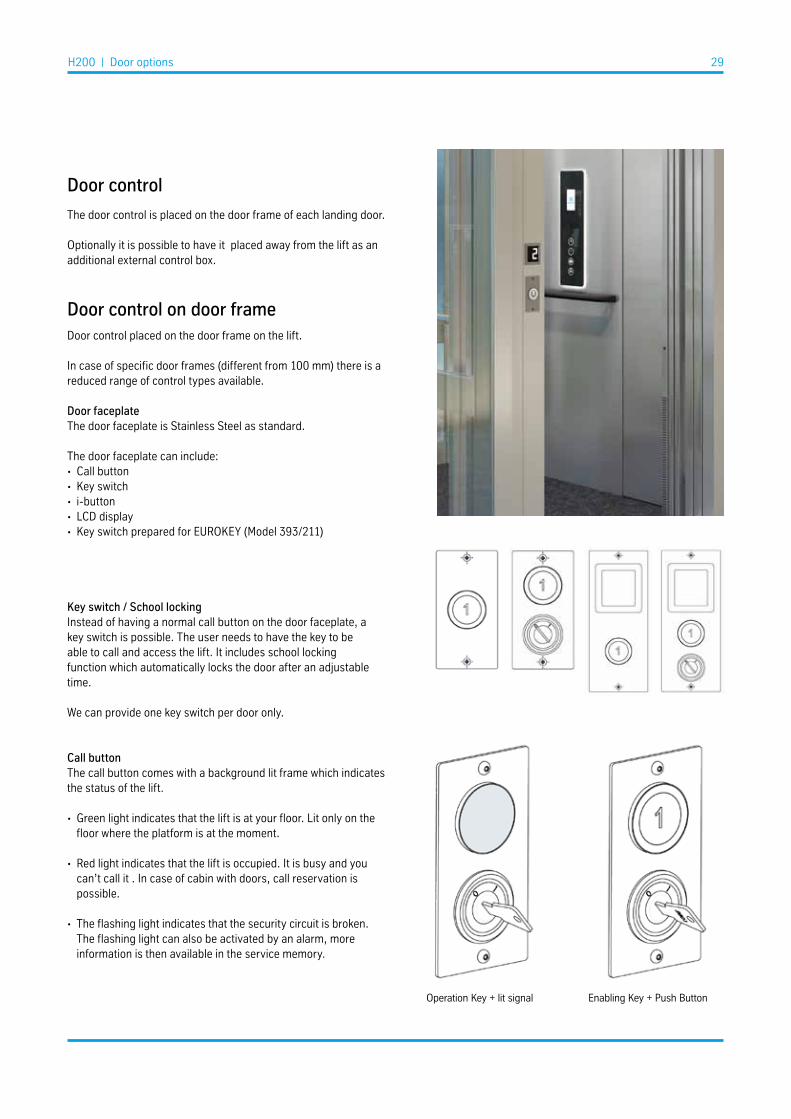
Door control
The door control is placed on the door frame of each landing door.
Optionally it is possible to have it placed away from the lift as an additional external control box.
Door control on door frameDoor control placed on the door frame on the lift.
In case of specific door frames (different from 100 mm) there is a reduced range of control types available.
Door faceplateThe door faceplate is Stainless Steel as standard.
The door faceplate can include:• Call button• Key switch• i-button• LCD display• Key switch prepared for EUROKEY (Model 393/211)
Key switch / School lockingInstead of having a normal call button on the door faceplate, a key switch is possible. The user needs to have the key to be able to call and access the lift. It includes school locking function which automatically locks the door after an adjustable time.
We can provide one key switch per door only.
Call buttonThe call button comes with a background lit frame which indicates the status of the lift.
• Green light indicates that the lift is at your floor. Lit only on the floor where the platform is at the moment.
• Red light indicates that the lift is occupied. It is busy and you can’t call it . In case of cabin with doors, call reservation is possible.
• The flashing light indicates that the security circuit is broken. The flashing light can also be activated by an alarm, more information is then available in the service memory.
Operation Key + lit signal Enabling Key + Push Button

H200 | Door options 30
Cable control station – placed away from lift
Door control placed away from the lift in an external call box connected to the lift via a cable
Size: 130x70x55 mm without display 220x95x55 mm with display
Finish: The faceplate is stainless steel satin.
The call box can be Surface Mounted or Flush Mounted.
The Radio control station is available in three different configurations.It can be ordered in addition to the standard faceplate at landing or as remote sender from a specified floor to a different specified destination floor.
Max 1 remote sender per floor. Push button only.
Call box for flush wall mountingReccomended dimensions for mounting
11 11
6
10
5,5 8,8
21
5,5
14
22
55
60
65
125
55
60 90
215
H200 | Door options 31
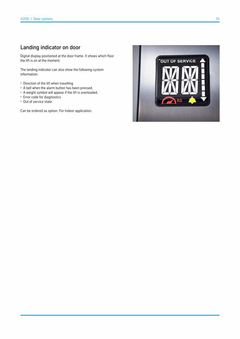
Landing indicator on door
Digital display positioned at the door frame. It shows which floor the lift is on at the moment.
The landing indicator can also show the following system information:
• Direction of the lift when travelling• A bell when the alarm button has been pressed.• A weight symbol will appear if the lift is overloaded.• Error code for diagnostics• Out of service state
Can be ordered as option. For Indoor application.

H200 | Shaft 32
Shaft structureno rivets, no silicon weatherproof and suitable for seismic conditions(*)
H200 can be delivered with its own patent pending metallic shaft.
The required headroom for the shaft structure (distance from top floor to top of shaft) depends on the type of top roof and landing doors. This includes a free height of 30mm between metal shaft roof and building for installation purpose.Elongation of the shaft is possible.
All the four sides will be cladded by the shaft panels in steel or glass, provided with a special gasket for water managementAlso availabale essential panels to be mounted with sylicon.It is highly recommended to use panels with gasket for outdoor installation. It is highly recommended to use steel panel on side G.
The lowest and the top panels on the guide side are always provided with a round axial aerator.
Typical Required Headroom with standard cabin. Please refer to "Feasibility information" section for futher details
ModelCabin without
DoorsCabin Folding
DoorsCabin Sliding
Doors
H200 in concrete shaft 2300 mm 2320 mm 2450 mm /
2500 mm
H200 metal shaft header diagonals
- indoor2450 mm 2450 mm 2590 mm
H200 metal shaft flat roof - indoor 2470 mm 2470 mm 2610 mm
H200 metal shaft inclined roof -
outdoor2490 mm 2490 mm 2630 mm
(*) According to Eurocode, Seismic verification shall be checked with specific calculations and definiton of fixing points for the specific unit.
Shaft ceiling type
• Header diagonal• Flat roof 1 or 2 pieces, depending on dimensions• Inclined roof 1 or 2 pieces, depending on dimensions
RampIf the lift is installed without a pit, a ramp is mandatory according to EN81.41. Please check compliance to local regulations.Usually a boardwalk with low incline is executed at the building site.Optionally we can provide a ramp 120 mm high and 1000 mm long, made of aluminium and preventing slipping.

Shaft panels
Galvanized steel panels RAL painted at customer choice.Glass panels with laminated safety glass 8/9 mm (4+0.76+4).or a mix of the two on different sides of the shaft.
Sealing is granted by the perimetral gasket.Alternatively a conventional solution for sealing by silicon is available.
Different types of glass are available:
1 Transparent
2 Smokey Grey
3 Smokey Satin
4 Opaline
5 Half Reflecting
H200 | Shaft 33
Essential PanelsIf your preference is for a conventional valid basic solution or higher thickness safety glasses are needed, different shaft panels are available with the following Essential features:
Glass panels with laminated safety glass 10/11 mm (5+0.76+5).Silicon instead of gasket for the shaft panels
In case of outdoor application, panels with gasket are recommended.
Easy Snap SystemThe snap-lock fastening system permits a quick installation of the horizontal and vertical cladding frames without any additional fastening element.

H200 | Feasibility and sizes 34
Feasibility Information
Narrow and Wide
The H200 is provided with different layouts according to the cabin dimensions.The distance between guides (DBG) can vary depending on the platform/cabin width.
FPR - Full Panel Wall with CeilingNDC - Cabin without DoorsFDC - Cabin with Folding DoorsSDC - Cabin with Sliding Doors
The feasibility diagram explains the limits for platform dimensions (CW xCD) based on technical feasibility.
As a standard rule, H200 will be designed and delivered considering the minimum nominal load according to the EN code which state250 kg/m2 unless differently specified for the destination country.
In case you would like to have an higher rated load, it's highly recommended to specifiy it at order stage because the calculationwill change accordingly.
Some limitations exist for higher travel and heavier cabins. Please refer to "Higher Travel" section in next pages.
Typical dimensions
In these catalogue we have preselected some typical plan sizes which represent the most frequently ordered ones, worldwide.
These are our "Predefined plan sizes", completely described in this catalogue. These are available as a standard solution, including the preselected door sizes and types.
It is always possible to ask for different cabin dimensions or door types and door displacements, provided these are within our feasibility and offer portfolio. Our engineers will design the lift according to your requirements, with extra delivery time and extra price.
We can distinguish among:
• "Modular plan sizes" which are designed using the standard modular elements of our metal shaft structure• "At measure plan sizes" - which are instead completely customised.
Please refer to the annexes and contact us for further information.

H200 | Feasibility and sizes 35
Solutions with Cabin Doors
FDC - Cabin with Folding DoorsSDC - Cabin with Sliding Doors
These solutions allow for a fully automatic operation.The diagram is optimized to offer the most typical and functional cofigurations.
Some limitations exist for higher travel and heavier cabins.Please refer to feasibility tables in next pages.
Formulas to pass from Cabin Dimensions to Shaft Dimensionsdepend on cabin layout and access sides. These technical informationare available un the annexes to this product catalogue.
(*) CW>1400 mm or CD>1200 mm
feasible with weight check
Cabin without Doors
These two configurations allow to have the widest plan sizes in our cabin portfolio.From a minimum width of 750 mm up to the biggest platform of 1600x1100 mm
Full Panel Wall with Ceiling
This configuration allow to have the narrowest and widest dimensions in our portfolio.From a minimum width of 560 mm up to the biggest platform of 1600x1100 mm
Some limitations exist for higher travel and heavier cabins. Please refer to Feasibility section in the next pages
Cabin to Masonry Shaft
SW = CW + 120SD = CD + 345
Cabin to Metal Shaft(external dimensions)
EW = CW + 200ED = CD + 425
(*) CW<630 feasible with doors on side A and/or C only
630*
Cabin to Masonry Shaft
SW = CW + 120SD = CD + 345
Cabin to Metal Shaft(external dimensions)
EW = CW + 200ED = CD + 425

H200 | Feasibility and sizes 36
Travel (mm) Full Panel with CeilingCabin without Doors /
Cabin with Automatic Doors
Lower than 12600full
availability
Refer to "Panoramic Sides"
fesibility table
12601 - 13100 Refer to "Higher Travel" fesibility table 13101 - 13600 Refer to
"Higher Travel" fesibility table13601 -15100
NOT FeasibleHigher than 15100 NOT Feasible
Higher Travel
This table apply for tavel higher than 12600 mm only.
Within the feasibility diagrams of the previous pages and depending on cabin types and lift travel, feasibility check could be needed.The tables below have been prepared to guide you through the feasibilty check in limit situations (higher travel / heavier cabins)
Travel Full Panel with Ceiling Cabin w/o Doors Cabin with Automatic Doors
Max Rated Load up to 1 m2 up to 1,3 m2 up to 1,8 m2 up to 1,3 m2 up to 1,6 m2 up to 1,3 m2 up to 1,6 m2
MAx Floor Area up to 250 kg up to 325 kg up to 450 kg up to 325 kg up to 400 kg up to 325 kg up to 400 kg
12600 - 13100 fullavailability
fullavailability
fullavailability
feasibility check
feasibility check
feasibility check
feasibility check
13100 - 13600 fullavailability
fullavailability
feasibility check
feasibility check
feasibility check
feasibility check NOT feasible
13600 - 14100 fullavailability
fullavailability NOT feasible feasibility
check NOT feasible NOT feasible NOT feasible
14100 - 14600 fullavailability
feasibility check NOT feasible feasibility
check NOT feasible NOT feasible NOT feasible
14600 - 15100 fullavailability NOT feasible NOT feasible NOT feasible NOT feasible NOT feasible NOT feasible
Feasibility Tables according to EN code - rated load 250 kg/m2 - travel higher than 12600 mm
H200 | Feasibility and sizes 37
Sta
ndar
d C
abin
1 ac
cess
Floor Area Number of Panoramic Sides
- 1 2 3
up to 1,3 m2 fullavailability
fullavailability
fullavailability
1,3 - 1,44 m2 fullavailability
fullavailability
fullavailability
> 1,44 m2 fullavailability
fullavailability
fullavailability
Eleg
ance
Cab
in
HPL
Wal
ls1
acce
ss
Floor Area Number of Panoramic Sides
- 1 2 3
up to 1,3 m2 fullavailability
fullavailability
fullavailability
1,3 - 1,44 m2 fullavailability
fullavailability
fullavailability
> 1,44 m2 Weightcheck
Weightcheck
Carpet or PVC floor only
Eleg
ance
Cab
in
Ste
el W
alls
1 ac
cess
Floor Area Number of Panoramic Sides
- 1 2 3
up to 1,3 m2 fullavailability
fullavailability
fullavailability
1,3 - 1,44 m2 fullavailability
fullavailability
fullavailability
> 1,44 m2 fullavailability
Weightcheck
Carpet or PVC floor only
Eleg
ance
Cab
in
HPL
Wal
ls2
acce
ss
Floor Area Number of Panoramic Sides
- 1 2 3
up to 1,3 m2 fullavailability
fullavailability
fullavailability
1,3 - 1,44 m2 fullavailability
fullavailability
fullavailability
> 1,44 m2 Carpet or PVC floor only
Feasibility Check
Feasibility Check
Eleg
ance
Cab
in
Ste
el W
alls
2 ac
cess
Floor Area Number of Panoramic Sides
- 1 2 3
up to 1,3 m2 fullavailability
fullavailability
fullavailability
1,3 - 1,44 m2 fullavalability
fullavalability
fullavalability
> 1,44 m2 Weightcheck
Carpet or PVC floor only
Feasibility Check
Sta
ndar
d C
abin
2 ac
cess
Floor Area Number of Panoramic Sides
- 1 2 3
up to 1,3 m2 fullavailability
fullavailability
fullavailability
1,3 - 1,44 m2 fullavailability
fullavailability
fullavailability
> 1,44 m2 fullavailability
fullavailability
Weightcheck
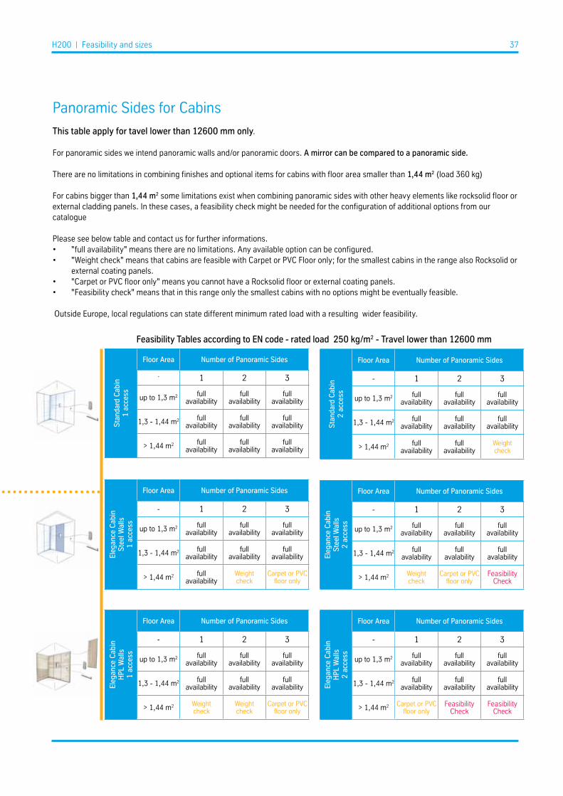
Panoramic Sides for Cabins
This table apply for tavel lower than 12600 mm only.
For panoramic sides we intend panoramic walls and/or panoramic doors. A mirror can be compared to a panoramic side.
There are no limitations in combining finishes and optional items for cabins with floor area smaller than 1,44 m2 (load 360 kg)
For cabins bigger than 1,44 m2 some limitations exist when combining panoramic sides with other heavy elements like rocksolid floor or external cladding panels. In these cases, a feasibility check might be needed for the configuration of additional options from our catalogue
Please see below table and contact us for further informations.• "full availability" means there are no limitations. Any available option can be configured.• "Weight check" means that cabins are feasible with Carpet or PVC Floor only; for the smallest cabins in the range also Rocksolid or
external coating panels.• "Carpet or PVC floor only" means you cannot have a Rocksolid floor or external coating panels.• "Feasibility check" means that in this range only the smallest cabins with no options might be eventually feasible.
Outside Europe, local regulations can state different minimum rated load with a resulting wider feasibility.
Feasibility Tables according to EN code - rated load 250 kg/m2 - Travel lower than 12600 mm
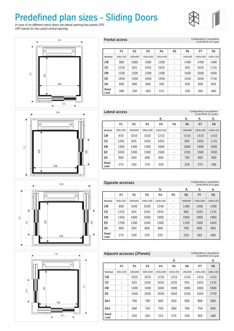
Predefined plan sizes - Sliding Doors
Frontal access
Lateral access
Opposite accesses
P1 P2 P3 P4 P5 P6 P7 P8
Nominal 900x1200 1000x800 1000x1000 1200x1000 - 1400x900 1400x1000 1400x1100
CW 900 1080 1000 1200 - 1400 1400 1400
CD 1235 835 1035 1035 - 935 1035 1135
EW 1200 1300 1200 1400 - 1600 1600 1600
ED 1850 1450 1650 1650 - 1550 1650 1750
DA 600 600 600 700 - 850 850 850
Rated Load 280 250 260 315 330 365 400
P1 P2 P3 P4 P5 P6 P7 P8
Nominal 900x1200 1000x800 1000x1000 1200x1000 - 1400x900 1400x1000 1400x1100
CW 910 1010 1010 1210 - 1410 1410 1410
CD 1205 855 1055 1055 - 905 1055 1135
EW 1300 1400 1400 1600 - 1800 1800 1800
ED 1650 1300 1500 1500 - 1350 1500 1650
DA 900 650 800 800 - 700 800 900
Rated Load 275 250 270 320 320 375 400
P1 P2 P3 P4 P5 P6 P7 P8
Nominal 900x1200 1000x800 1000x1000 1200x1000 - 1400x900 1400x1000 1400x1100
CW 890 1040 1040 1240 - 1400 1400 1400
CD 1235 835 1035 1035 - 905 1035 1135
EW 1450 1600 1600 1800 - 1960 1960 1960
ED 1700 1300 1500 1500 - 1350 1500 1650
DA 900 650 800 800 - 700 800 900
Rated Load 275 250 270 325 320 365 400
In case of no different notice doors are lateral opening two panels (2P).(4P) stands for four panel central opening
Configurations in accordance to the EN 81-41 in grey
Configurations in accordance to the EN 81-41 in grey
Configurations in accordance to the EN 81-41 in grey
Adjacent accesses (2Panels)
P1 P2 P3 P4 P5 P6 P7 P8
Nominal 900x1200 1000x800 1000x1000 1200x1000 1200x1200 1400x900 1400x1000 1400x1100
CW - 1010 1010 1210 1210 1410 1410 1410
CD - 835 1035 1035 1235 935 1035 1135
EW - 1400 1400 1600 1600 1800 1800 1800
ED - 1450 1650 1650 1850 1550 1650 1750
DA1 - 700 700 850 850 900 900 900
DA2 - 600 750 750 900 700 750 800
Rated Load - 250 265 315 375 330 365 400
Configurations in accordance to the EN 81-41 in grey
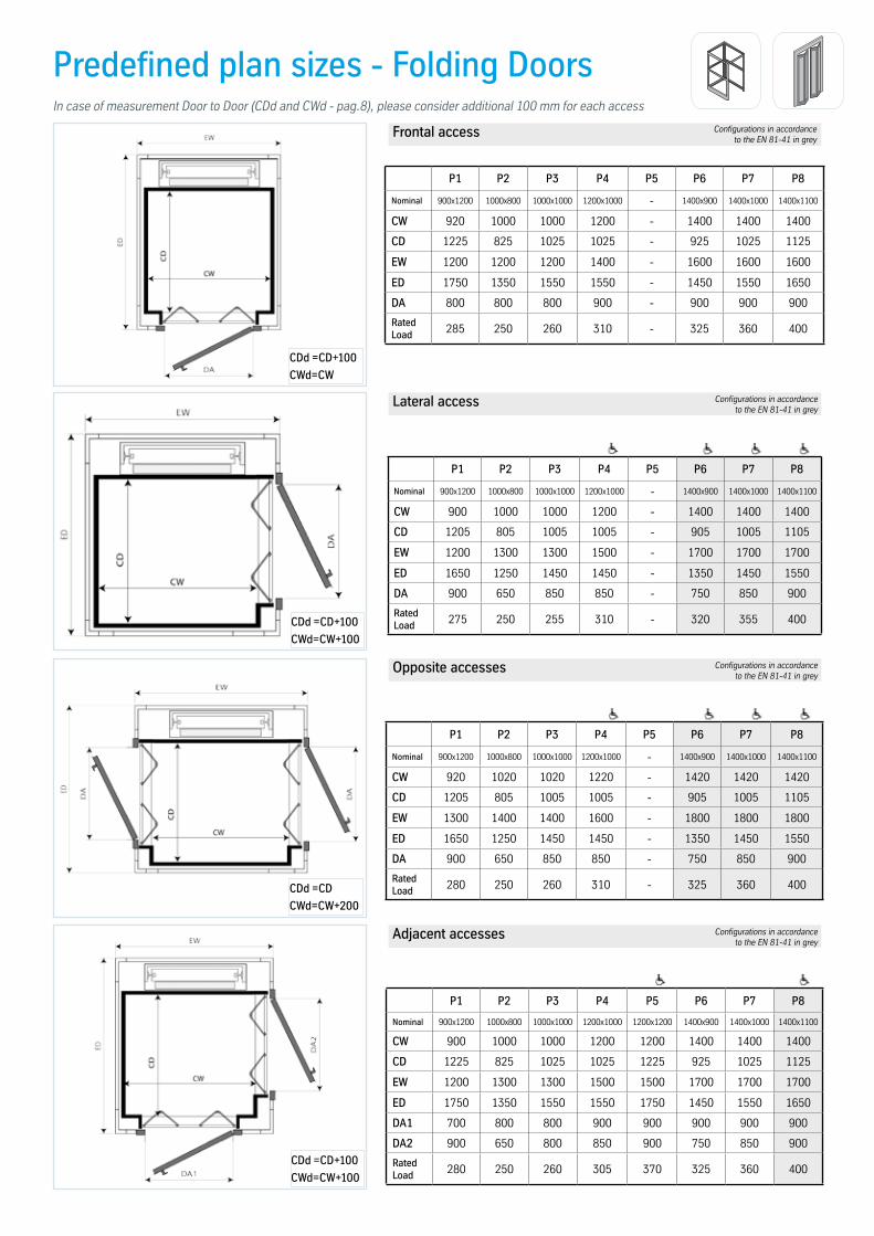
Predefined plan sizes - Folding Doors
Frontal access
Lateral access
Opposite accesses
Adjacent accesses
P1 P2 P3 P4 P5 P6 P7 P8
Nominal 900x1200 1000x800 1000x1000 1200x1000 - 1400x900 1400x1000 1400x1100
CW 920 1000 1000 1200 - 1400 1400 1400
CD 1225 825 1025 1025 - 925 1025 1125
EW 1200 1200 1200 1400 - 1600 1600 1600
ED 1750 1350 1550 1550 - 1450 1550 1650
DA 800 800 800 900 - 900 900 900
Rated Load 285 250 260 310 - 325 360 400
P1 P2 P3 P4 P5 P6 P7 P8
Nominal 900x1200 1000x800 1000x1000 1200x1000 - 1400x900 1400x1000 1400x1100
CW 900 1000 1000 1200 - 1400 1400 1400
CD 1205 805 1005 1005 - 905 1005 1105
EW 1200 1300 1300 1500 - 1700 1700 1700
ED 1650 1250 1450 1450 - 1350 1450 1550
DA 900 650 850 850 - 750 850 900
Rated Load 275 250 255 310 - 320 355 400
P1 P2 P3 P4 P5 P6 P7 P8
Nominal 900x1200 1000x800 1000x1000 1200x1000 - 1400x900 1400x1000 1400x1100
CW 920 1020 1020 1220 - 1420 1420 1420
CD 1205 805 1005 1005 - 905 1005 1105
EW 1300 1400 1400 1600 - 1800 1800 1800
ED 1650 1250 1450 1450 - 1350 1450 1550
DA 900 650 850 850 - 750 850 900
Rated Load 280 250 260 310 - 325 360 400
P1 P2 P3 P4 P5 P6 P7 P8
Nominal 900x1200 1000x800 1000x1000 1200x1000 1200x1200 1400x900 1400x1000 1400x1100
CW 900 1000 1000 1200 1200 1400 1400 1400
CD 1225 825 1025 1025 1225 925 1025 1125
EW 1200 1300 1300 1500 1500 1700 1700 1700
ED 1750 1350 1550 1550 1750 1450 1550 1650
DA1 700 800 800 900 900 900 900 900
DA2 900 650 800 850 900 750 850 900
Rated Load 280 250 260 305 370 325 360 400
Configurations in accordance to the EN 81-41 in grey
Configurations in accordance to the EN 81-41 in grey
Configurations in accordance to the EN 81-41 in grey
Configurations in accordance to the EN 81-41 in grey
CDd =CD+100
CWd=CW
CDd =CD+100
CWd=CW+100
CDd =CD
CWd=CW+200
CDd =CD+100
CWd=CW+100
In case of measurement Door to Door (CDd and CWd - pag.8), please consider additional 100 mm for each access

Predefined plan sizes -
Frontal access
Lateral access
Opposite accesses
Adjacent accesses
P1 P2 P3 P4 P5 P6 P7 P8
Nominal 900x1200 1000x800 1000x1000 1200x1000 - 1400x900 1400x1000 1400x1100
CW 900 1000 1000 1200 - 1400 1400 1400
CD 1225 825 1025 1025 - 925 1025 1125
EW 1100 1200 1200 1400 - 1600 1600 1600
ED 1650 1250 1450 1450 - 1350 1450 1550
DA 700 700 800 900 - 900 900 900
Rated Load 280 250 260 310 - 325 360 400
P1 P2 P3 P4 P5 P6 P7 P8
Nominal 900x1200 1000x800 1000x1000 1200x1000 - 1400x900 1400x1000 1400x1100
CW 900 1000 1000 1200 - 1400 1400 1400
CD 1225 825 1025 1025 - 925 1025 1125
EW 1100 1200 1200 1400 - 1600 1600 1600
ED 1650 1250 1450 1450 - 1350 1450 1550
DA 900 700 850 900 - 800 900 900
Rated Load 280 250 260 310 - 325 360 400
P1 P2 P3 P4 P5 P6 P7 P8
Nominal 900x1200 1000x800 1000x1000 1200x1000 1200x1200 1400x900 1400x1000 1400x1100
CW 900 1000 1000 1200 1200 1400 1400 1400
CD 1225 825 1025 1025 1225 925 1025 1125
EW 1100 1200 1200 1400 1400 1600 1600 1600
ED 1650 1250 1450 1450 1650 1350 1450 1550
DA1 700 700 800 900 900 900 900 900
DA2 900 700 850 900 900 800 900 900
Rated Load 280 250 260 310 370 325 360 400
Configurations in accordance to the EN 81-41 in grey
Configurations in accordance to the EN 81-41 in grey
Configurations in accordance to the EN 81-41 in grey
Configurations in accordance to the EN 81-41 in grey
Full Panel with Ceiling and Cabin w/o Doors

CW
CD
In case of Full Panel wit ceiling, lifts with accesses on three different sides are feasible, provided that maximum two accesses at the same floor are there.
Plan dimensions are the same as in the previous table.

Predefined plan sizes - Sliding Doors
Frontal access
Lateral access
Opposite accesses
P1 P2 P3 P4 P5 P6 P7 P8
Nominal 900x1200 1000x800 1000x1000 1200x1000 - 1400x900 1400x1000 1400x1100
CW 900 1080 1000 1200 - 1400 1400 1400
CD 1235 835 1035 1035 - 935 1035 1135
SW 1120 1220 1140 1340 - 1540 1540 1540
SD 1770 1370 1570 1570 - 1470 1570 1670
DA 600 600 600 700 - 850 850 850
Rated Load 280 250 260 315 330 365 400
P1 P2 P3 P4 P5 P6 P7 P8
Nominal 900x1200 1000x800 1000x1000 1200x1000 - 1400x900 1400x1000 1400x1100
CW 910 1010 1010 1210 - 1410 1410 1410
CD 1205 855 1055 1055 - 905 1055 1135
SW 1220 1320 1320 1520 - 1720 1720 1720
SD 1570 1220 1420 1420 - 1270 1420 1550
DA 900 650 800 800 - 700 800 900
Rated Load 275 250 270 320 320 375 400
P1 P2 P3 P4 P5 P6 P7 P8
Nominal 900x1200 1000x800 1000x1000 1200x1000 - 1400x900 1400x1000 1400x1100
CW 890 1040 1040 1240 - 1400 1400 1400
CD 1235 835 1035 1035 - 905 1035 1135
SW 1370 1520 1520 1720 - 1880 1880 1880
SD 1620 1220 1420 1420 - 1270 1420 1550
DA 900 650 800 800 - 700 800 900
Rated Load 275 250 270 325 320 365 400
In case of no different notice doors are lateral opening two panels (2P).(4P) stands for four panel central opening
Configurations in accordance to the EN 81-41 in grey
Configurations in accordance to the EN 81-41 in grey
Configurations in accordance to the EN 81-41 in grey
Adjacent accesses (2Panels)
P1 P2 P3 P4 P5 P6 P7 P8
Nominal 900x1200 1000x800 1000x1000 1200x1000 1200x1200 1400x900 1400x1000 1400x1100
CW - 1010 1010 1210 1210 1410 1410 1410
CD - 835 1035 1035 1235 935 1035 1135
SW - 1320 1320 1520 1520 1720 1720 1720
SD - 1370 1570 1570 1770 1470 1570 1670
DA1 - 700 700 850 850 900 900 900
DA2 - 600 750 750 900 700 750 800
Rated Load - 250 265 315 375 330 365 400
Configurations in accordance to the EN 81-41 in grey

Predefined plan sizes - Folding Doors
Frontal access
Lateral access
Opposite accesses
Adjacent accesses
P1 P2 P3 P4 P5 P6 P7 P8
Nominal 900x1200 1000x800 1000x1000 1200x1000 - 1400x900 1400x1000 1400x1100
CW 920 1000 1000 1200 - 1400 1400 1400
CD 1225 825 1025 1025 - 925 1025 1125
SW 1060 1140 1140 1340 - 1540 1540 1540
SD 1670 1270 1470 1470 - 1370 1470 1570
DA 800 800 800 900 - 900 900 900
Rated Load 285 250 260 310 - 325 360 400
P1 P2 P3 P4 P5 P6 P7 P8
Nominal 900x1200 1000x800 1000x1000 1200x1000 - 1400x900 1400x1000 1400x1100
CW 900 1000 1000 1200 - 1400 1400 1400
CD 1205 805 1005 1005 - 905 1005 1105
SW 1120 1220 1220 1420 - 1620 1620 1620
SD 1570 1170 1370 1370 - 1270 1370 1470
DA 900 650 850 850 - 750 850 900
Rated Load 275 250 255 310 - 320 355 400
P1 P2 P3 P4 P5 P6 P7 P8
Nominal 900x1200 1000x800 1000x1000 1200x1000 - 1400x900 1400x1000 1400x1100
CW 920 1020 1020 1220 - 1420 1420 1420
CD 1205 805 1005 1005 - 905 1005 1105
SW 1220 1320 1320 1520 - 1720 1720 1720
SD 1570 1170 1370 1370 - 1270 1370 1470
DA 900 650 850 850 - 750 850 900
Rated Load 280 250 260 310 - 325 360 400
P1 P2 P3 P4 P5 P6 P7 P8
Nominal 900x1200 1000x800 1000x1000 1200x1000 1200x1200 1400x900 1400x1000 1400x1100
CW 900 1000 1000 1200 1200 1400 1400 1400
CD 1225 825 1025 1025 1225 925 1025 1125
SW 1120 1220 1220 1420 1420 1620 1620 1620
SD 1670 1270 1470 1470 1670 1370 1470 1570
DA1 700 800 800 900 900 900 900 900
DA2 900 650 800 850 900 750 850 900
Rated Load 280 250 260 305 370 325 360 400
Configurations in accordance to the EN 81-41 in grey
Configurations in accordance to the EN 81-41 in grey
Configurations in accordance to the EN 81-41 in grey
Configurations in accordance to the EN 81-41 in grey
CDd =CD+100
CWd=CW
CDd =CD+100
CWd=CW+100
CDd =CD
CWd=CW+200
CDd =CD+100
CWd=CW+100
In case measurement Door to Door (CDd and CWd) can be accepted, please consider additional 100 mm for each access

Predefined plan sizes -
Frontal access
Lateral access
Opposite accesses
Adjacent accesses
P1 P2 P3 P4 P5 P6 P7 P8
Nominal 900x1200 1000x800 1000x1000 1200x1000 1200x1200 1400x900 1400x1000 1400x1100
CW 900 1000 1000 1200 1200 1400 1400 1400
CD 1225 825 1025 1025 1225 925 1025 1125
SW 1020 1120 1120 1320 1320 1520 1520 1520
SD 1570 1170 1370 1370 1570 1270 1370 1470
DA 700 700 800 900 900 900 900 900
Rated Load 280 250 260 310 370 325 360 400
P1 P2 P3 P4 P5 P6 P7 P8
Nominal 900x1200 1000x800 1000x1000 1200x1000 1200x1200 1400x900 1400x1000 1400x1100
CW 900 1000 1000 1200 1200 1400 1400 1400
CD 1225 825 1025 1025 1225 925 1025 1125
SW 1020 1120 1120 1320 1320 1520 1520 1520
SD 1570 1170 1370 1370 1570 1270 1370 1470
DA 900 700 850 900 900 800 900 900
Rated Load 280 250 260 310 370 325 360 400
P1 P2 P3 P4 P5 P6 P7 P8
Nominal 900x1200 1000x800 1000x1000 1200x1000 1200x1200 1400x900 1400x1000 1400x1100
CW 900 1000 1000 1200 1200 1400 1400 1400
CD 1225 825 1025 1025 1225 925 1025 1125
SW 1020 1120 1120 1320 1320 1520 1520 1520
SD 1570 1170 1370 1370 1570 1270 1370 1470
DA1 700 700 800 900 900 900 900 900
DA2 900 700 850 900 900 800 900 900
Rated Load 280 250 260 310 370 325 360 400
Configurations in accordance to the EN 81-41 in grey
Configurations in accordance to the EN 81-41 in grey
Configurations in accordance to the EN 81-41 in grey
Configurations in accordance to the EN 81-41 in grey
Full Panel with Ceiling and Cabin w/o Doors

Cabin type Access side safety device
Cabin netheight (mm)
Cabin accessnet height (mm)
Door accessnet height (mm)
min Free Height needed in case of
masonry shaft (mm)
Min Free height needed in case of metal shaft (mm)
Full Panel Wall with Roof Photocells
1920 1900 1900 2100 2350
2020 2000 2000 2200 2450
2100 2080 2000 2300 2450
2200 2180 2100 2400 2550
Standard Cabin without doors Photocells
1920 1900 1900 2100 2350
2020 2000 2000 2200 2450
2100 2080 2000 2300 2450
2200 2180 2100 2400 2550
Standard cabin with folding
doors-
2020 1940 1900 2240 2350
2100 2020 2000 2320 2450
2200 2120 2100 2420 2550
Standard cabin with sliding
doors
Photocells2100 2000 2000 2450 2590
2200 2100 2100 2550 2690
Light Curtains2100 2000 2000 2500 2590
2200 2100 2100 2600 2690
Elegance Cabin without doors
Photocells2030 (*) 2020 2000 2300 2450
2130 (*) 2120 2100 2400 2550Light curtains 2030 (*) 2020 2000 2300 2450
Elegance Cabin with folding
doors-
2030 (*) 2020 2000 2320 2450
2130 (*) 2120 2100 2420 2550
Elegance Cabin with sliding
doors
Photocells 2030 (*) 2000 2000 2450 2590
2130 (*) 2100 2100 2550 2690
Light Curtains2030 (*) 2000 2000 2500 2590
2130 (*) 2100 2100 2600 2690
(*) Cabin net height reduced by 70 mm counterceiling
The Free Height avaliable in the building between the last floor and the lower obstacle at the top (e.g. building roof) should be higher than the encumbrance of the lift (headroom). Required headroom depends on the cabin and doors type.
Standard situation is highlighted in grey. Different solutions could be feasible on specific requests with special execution
• reduced height to overcome issues related to lower free height
• increased height where requested.
Please refer to the table below and contact our Drawing Department.
Free height per cabin type

H200 | Shaft 46
Configuration for delivery
• The lift is delivered with the main parts already assembled to optimize weight and installation time.
• Electrical cables are pre-wired and prepared with connectors.
• Small parts are packaged into specific identifiable boxes.
• T-guides are already "cut to length" to reduce installation time at site.
• The lift is always delivered with an optimized package to reduce logistic costs and product breakage during transportation.
Electrical cabinetThe electrical panel and the hydraulic control unit shall be housed in a location, or in an appropriate container, which will protect them from the atmospheric elements.
Our platform lift can be equipped with a “Cabinet” specifically designed to contain the “Electrical Control Panel and Hydraulic Control Unit”.In the event that the client prefers not to purchase our Cabinet, He/She may proceed differently providing that prescriptions and specifications are fulfilled.Please refer to our Pre-Installation manual for specific information.
The standard position of the electrical cabinet is at the bottom floor within a maximum distance of 5 meters from the Guide side of the lift. Optionally this distance can be increased up to 10 meters thanks to a specific set of cables.
Finishes: Standard RAL 7001; Optionally painted at choice.
The Cabinet is suitable for outdoor application, provided it is positioned in a protected area of the building or equipped with "suitable rain protection" (e.g. canopy) to avoid unwanted water infiltration inside the cabinet. It should not be exposed to direct rain and to aggressive and corrosive environment,
Dimensions: 750 x 460 x 1500 mm

H200 | Communication & drive 47
Communication & drive
Two way communicationTwo way communication is mandatory according to EN81-41. Choose from one of the following options.
AutodialerEquipment for emergency calls. Integrated in the control operation panel. Dials automatically when the alarm button is kept pressed for 3 seconds. When unanswered after a predefined time, the call is automatically forwarded to the next pre-set number. The autodialer can be equipped with a GSM module.
PhoneThe telephone works as a standard telephone but is intended for emergency calls only. The phone is mounted on the platform panel, usually next to the Control Panel.
Valuable standard features Battery operated emergency loweringBattery operated emergency lowering is a standard feature in every lift. When there is a power failure, you can still travel downwards and get out by yourself. It is possible to run the lift to the nearest lower level pressing a destination button in the Control Operation Panel.
The battery guard ensures that the batteries are not damaged and that there is enough power to run the lift in the case of a power cut.
It ensures that the lift is turned off when the battery charge reaches a low predefined level.
Soft start and stop.
It provides the lift with a smooth start and stop.Two speeds - hydraulic unit comes as a standard feature on all the lifts.
Safety is our DNA.With its own SIL3 certified electronics, H200 sets itself apart from the crowd and beyond the mandatory in the Home lift market.

H200 | FAQ 48
metallic colours
FAQ
1. Can I have the lift painted in any colour?
The H200 shaft structure and panels can be painted in any RAL colour .The following choices are available:
• Shaft structure and panels can be delivered:• painted in Typical RAL colour• painted in Any RAL colour at choice • painted in Metallic colour (R06-R07-R09-R10)
The landing doors can be delivered:• in the same colour as shaft• in a matching skinplate finish (sliding doors only)• in any other finish from our portfolio with full freedom of choice, even
different finishes for different doors.
Painting for Shaft, Doors, Cabin Walls is powder coating with orange peel finish (grade coarse), visual gloss 80-90.
Any RAL colour means any RAL colour from the 213 colour in the RAL chart K7 classic. Pearl and Metal colours excluded.Typical RAL colours from the table to the right are available with shorter lead times and a lower price.Metallic colours are our selection of metallic paintings on a specifically prepared surface.Samples kit of Typical RAL and Metallic colours are available on request. All parts can show small colour differences, this is normal and unavoidable. While we take every precaution to minimize visible differences, this cannot be guaranteed.
2. To which standards do the lifts comply?
The H200 complies with the Machine Directive 2006/42/EC, by following the harmonized standard EN 81-41.
Lifts with speed up 0,15 m/s are type approved and CE marked.
CE Certificates are available on partner desktop.Specific declarations according to local codes can be provided on request.
Nomenclature will change according to the different specifications. See side table with model codes.
orange peel finish (grade coarse)
Typical Colours
RAL Skinplate
RAL 9003 A1; PPS10
RAL 9010 A4
RAL 1013 A13; PPS11
RAL 1015 G1
RAL 5024 B13
RAL 7035 N1; PPS1
RAL 7037 Metal Like
R06 (RAL9006) R07 (RAL9007)
R09 R10
H200 Nomenclature
Model Code Cabin Doors Certification
HY04 NOCE type approved
HY41 YES

H200 | FAQ 49
3. What are the reaction forces on the building and the forces on the fixings which support the frame to the wall
Details regarding the forces are specifically provided for each unit in the technical dossier. As a general information here are indicated typical loads according to typical conditions of external agents (wind, snow, temperature) and typical fixing solutions of the Home lifts to the building.
Reaction forces from the lift to the building floor:• The lift applies to the pit on the area "P" a force function of the travel.
This force can be considered uniformly distributed onto the base plate.• The metal shaft applies to the base area "S" a force function of the travel.
This force is applied to the four corners' plate of the shaft structure.• Maximum force as a function of the lift´s travel.
Reaction Force on the wall (rail side) - Concrete shaft:• The force is distributed to the wall through each crossbeam.• Vertical distance between each crossbeam is on average 1200 mm • Maximum force applied to each fixing point.
• Maximum extraction load is lower than 2,5 kN for each fixing point
Reaction Force on the wall - Metal shaft structure:• The metal structure shall be fixed to the existing building typically every
2000 mm in height through expansion bolts.• A wide range of fixing solutions is available to cover the most stringent
applications.• Loads in typical conditions never exceed 3 kN for each fixing point. • Further information are included in our Fixings guide.
Area“P”
Load from the lift to area “P”
Travel(m)
H200 [0,15 m/s]Dynamic Load
(kN)
2 12,1
4 12,7
6 13,3
8 13,8
10 14,4
12 15,0
14 15,6
15 15,9
Load from the lift to area “S”
Travel(m)
Total (kN)each corner
(kN)
specific on each corner
(N/mm2)
2 12 3 0,16
4 16 4 0,21
6 20 5 0,26
8 24 6 0,32
10 28 7 0,37
12 32 8 0,42
14 36 9 0,47
15 40 10 0,53
Area“S”
Fy
Fy
Fy
Fy
Fx
Fx
Fx
Fx
Speed (m/s) Fx guide side [kN] Fy guide side [kN]
<= 0,15 2,5 0,9
H200 | FAQ 50
4. What does it mean that the Shaft Structure is suitable for seismic conditions?
Our Shaft Structure is designed to be used also in locations where a seismic event can occur. Specifically, the structure has been checked according to the requirements of the Eurocodes and NTC2008 (Italian reference standard) which provide guidelines on the structural calculation in seismic conditions. Indeed, it is not possible to state a priori a degree of resistance according to an earthquake's strength scale. The structure must be checked according to the stratigraphic and topographical conditions of the soil and subsoil and of the predictable ground acceleration in these areas. The structure's behavior and its resisting capacities also depend on its geometry and boundary constraint conditions.
Specific verification could be becessary according to local regulation.Please contatct us for specific cases.
5. Can the Home Lift be installed if accessible spaces do exist below the Lift shaft?
As a general rule: YES, provide that the structure can sustain the reported dynamic loads.
6. Can the Home Lift be installed in an hoistway bigger than the value specified in the plan sizes table?
As a general rule: YES, provided that the maximum gap between the cabin and the shaft wall does not exceed 150 mm. Please contatct us for specific cases.
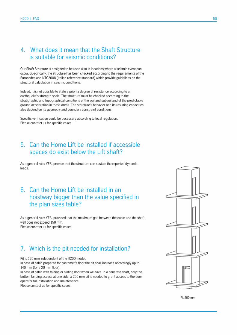
7. Which is the pit needed for installation?
Pit is 120 mm independent of the H200 model.In case of cabin prepared for customer's floor the pit shall increase accordingly up to 140 mm (for a 20 mm floor).In case of cabin with folding or sliding door when we have in a concrete shaft, only the bottom landing access at one side, a 250 mm pit is needed to grant access to the door operator for installation and maintenance.Please contact us for specific cases.
Pit 250 mm

H200 | FAQ 51
8. What is needed for outdoor application?
Oil heater is mandatory in case the lift is supposed to work below 5 °C Other options suggested for outdoor application are indicated in the price list.
The lift must be installed above ground level The lift pit must be drained and water should be directed away from the lift.
The lift is not water tight and water can leak into the lift via landing doors or shaft.Please protect doors and main cabinet from direct rain.
The Shaft outdoor kit include small canopies for landing doors.If the lift is installed outdoor and there is no roof over the doors, door canopies must be installed over the doors.The shaft panels with gasket are recommended for outdoor installation.
Installation is not recommended in salt or chlorine environment.For example in case of installation close to sea or close to a swimming pool, please contact our drawing office for specific solutions.
Installation is not recommended in environment with strong sun irradiation.The inside of the shaft can reach very high temperatures. Similarly, cold climatic conditions can cause very low temperatures in the shaft. These conditionsconstitute a potential danger to the user. Extreme caution is required when using the lift platform in such conditions. Inthis case it is advisable to contact a conditioning and air treatment specialist to identify the best solution to adopt.
Please refer to our pre-installation manual for specific information.

Features & Benefits
(*) Usage category: 1 according to VDI 4707-1. Measurement carried out on 08 November 2017. H200 Home lifts achieved the A class, the highest energy rating under the VDI 4707 classification. Actual performances are only indicative for similar units. Notified bodies only are entitled to perform measurements and classification.
H200 | Features & Benefits 52
you can always get out of the Home lift by yourself
If there is a power failure, you can always get out of the Home lift by yourself with automatic emergency lowering. Use the cabin buttons and the lift will take you to a pre-set lower floor where you can open the door and get out.
The safest lift of its kind
For safety we prefer to count on more than one system. The overspeed governor and brake is separate from the main drive system. The electronics are certified by a third party with the highest safety Integration level for units of this kind (SIL3).
Duty Cycle
Home lifts are intended for low traffic in residential or public buildings. H200 can run up to 36 travels per hour, depending on configurations and environmental conditions. In case of heavier use or higher travel, our lifts are provided with safety devices to standby the unit and prevent damages from overheating until the normal operation conditions are reset.
Energy efficiency
H200, tested in different configurations and speeds, has been rated as the best energy efficiency class, with stand-by consumption significantly below 30W and extremely low annual nominal consumption (*).
Low operation and maintenance cost
The entire portfolio of the thyssenkrupp Home lifts is based on a common electronics with CAN BUS connection granting easy diagnostic and maintenance.
Premium metal Shaft
thyssenkrupp’s metal shaft means the lift is weatherproof and suitable for seismic conditions, making it the ideal premium mobility enhancement for private homes.
versatile portfolio
More than 200 predefined plan sizes to fit everywhere in private and public buildings. Available also in customized dimensions with or without cabin doors.

H200 53
Annexes
DWG-H200
Includes the drawings of all the predefined plan sizes for H200 applications.
TAB-H200
Includes all the predefined and modular plan sizes for H200 applications in a tabular form with the main dimensions and information.
DGM-H200
Includes the feasibilty diagrams and the formulas to pass from Cabin dimensions to Shaft dimen-sions. It includes also useful indications between cabin sizes and door sizes.For experienced professionals, only.

H200 54
Model CodeHY04 / HY41
Product CodesHYxx-ES-yyyHYxx-ST-yyy
Commercial NamesH200 / V200
Document nameCAT-H200-01
DateJuly 2019