elevator-type polling systems - tau
TRANSCRIPT

Elevator-Type Polling Systems ∗
Ruth Shoham Uri Yechiali
Department of Statistics, School of Mathematical ScienceRaymond and Beverly Sackler Faculty of Exact Sciences
Tel Aviv University, Tel Aviv 69978, Israel
November 1992
AbstractThe basic polling system is a configuration of N queues attended by
a single server, usually in a cyclic order. In an Elevator-type pollingscheme, instead of moving in a cyclic fashion, the server scans thechannels back and forth, residing in each queue for a duration of timedetermined by the service discipline. Such systems have a wide varietyof applications in the areas of telecommunications, computer networks,manufacturing, maintenance and repair, etc.
In this work we apply a unified approach to study four Elevator-type polling systems, distinguished by their service regimes. Thesystem-models are called Elevator Exhaustive, Elevator Gated, El-evator Globally-Quasi-Exhaustive and Elevator Globally-Gated (theExhaustive, Gated and Globally-Gated disciplines were partially stud-ied in the literature). For each system we provide a comprehensiveanalyses regarding cycle times in the up and down directions, server’ssojourn times in the various channels in each direction, customers’waiting times, and channels’ queue sizes. Furthermore, we derive con-ditions under which the durations of the up and down cycles are thesame. The calculation of customers’ mean waiting times are based ona derivation of a general relation-formula that can be used in conjunc-tion with many other polling schemes.
∗Supported by a Grant from the France-Israel Scientific Cooperation (in ComputerScience and Engineering) between the French Ministry of Research and Technology andthe Israeli Ministry of Science and Technology, Grant Number 3321190.
1

1 Introduction
Queueing systems consisting of N queues (channels) served by a single serverwhich incurs switch-over periods when moving from one queue to anotherhave been widely studied in the literature and used as a central model for theanalysis of a wide variety of applications in the areas of telecommunications,computer networks, manufacturing, etc. Very often such applications aremodeled as a polling system in which the server visits the queues in a cyclicorder or according to some polling table (c.f. Baker & Rubin [1987]).
In many of these applications, as well as in most polling models, it iscommon to control the amount of service given to each queue during theserver’s visit. Two widely used policies are the Exhaustive and the Gatedregimes, whose analysis (for queues with infinite buffers) has been exten-sively studied in the literature (see Takagi [1986] and [1990]). Recently,the Globally-Gated and the Globally-Quasi-Exhaustive service regimes wereproposed by Boxma, Levy & Yechiali [1992], who provided a thorough anal-ysis of the cyclic Globally-Gated scheme. Boxma, Westsrate and Yechiali[1993] further extended the Globally-Gated model to include server interrup-tions, and applied it to a real-world repairman problem. A Globally-typeregime uses a time-stamp mechanism for its cyclic reservation: the serverperforms a Hamiltonian tour through the queues, and uses the instant ofcycle-beginning as a reference point of time. If (n1, n2, . . . , nN) is the state-vector of the number of customers present at the various queues at the startof the Hamiltonian tour (when all gates are globally closed) then, under theGlobally-Gated regime, the server serves exactly ni customers at queue i,whereas under the Globally-Quasi-Exhaustive discipline, the server residesin queue i for the duration of ni ordinary busy periods.
In this paper we concentrate on the Elevator-Type (scan) polling scheme:instead of moving cyclically through the channels, the server first servesthe channels in one direction, i.e. in the order 1, 2, ..., N (’up’ cycle) andthen reverses its orientation and serves the channels in the opposite direction(’down’ cycle), i.e. going through channels N,N − 1, ..., 1. Then it changesdirection again, and keeps moving in this manner back and forth. This typeof polling mechanism is encountered in many applications, e.g. it models acommon scheme of addressing a hard disk for writing (or reading) informationon (or from) different tracks. The Elevator scheme ’saves’ the return walkingtime from channel N to channel 1 (when compared to cyclic polling systems).
2
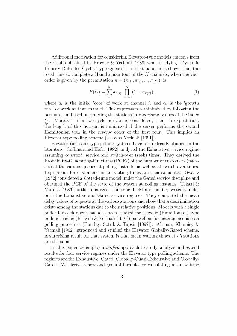
Additional motivation for considering Elevator-type models emerges fromthe results obtained by Browne & Yechiali [1989] when studying ”DynamicPriority Rules for Cyclic-Type Queues”. In that paper it is shown that thetotal time to complete a Hamiltonian tour of the N channels, when the visitorder is given by the permutation π = (π(1), π(2), ..., π(N)), is
E(C) =N∑i=1
aπ(i)
N∏r=i+1
(1 + απ(r)), (1)
where ai is the initial ’core’ of work at channel i, and αi is the ’growthrate’ of work at that channel. This expression is minimized by following thepermutation based on ordering the stations in increasing values of the indexai
αi. Moreover, if a two-cycle horizon is considered, then, in expectation,
the length of this horizon is minimized if the server performs the secondHamiltonian tour in the reverse order of the first tour. This implies anElevator type polling scheme (see also Yechiali [1991]).
Elevator (or scan) type polling systems have been already studied in theliterature. Coffman and Hofri [1982] analyzed the Exhaustive service regimeassuming constant service and switch-over (seek) times. They derived theProbability-Generating-Functions (PGFs) of the number of customers (pack-ets) at the various queues at polling instants, as well as at switch-over times.Expressions for customers’ mean waiting times are then calculated. Swartz[1982] considered a slotted-time model under the Gated service discipline andobtained the PGF of the state of the system at polling instants. Takagi &Murata [1986] further analyzed scan-type TDM and polling systems underboth the Exhaustive and Gated service regimes. They computed the meandelay values of requests at the various stations and show that a discriminationexists among the stations due to their relative positions. Models with a singlebuffer for each queue has also been studied for a cyclic (Hamiltonian) typepolling scheme (Browne & Yechiali [1991]), as well as for heterogeneous scanpolling procedure (Bunday, Sztrik & Tapsir [1992]). Altman, Khamisy &Yechiali [1992] introduced and studied the Elevator Globally-Gated scheme.A surprising result for that system is that mean waiting times at all stationsare the same.
In this paper we employ a unified approach to study, analyze and extendresults for four service regimes under the Elevator type polling scheme. Theregimes are the Exhaustive, Gated, Globally-Quasi-Exhaustive and Globally-Gated. We derive a new and general formula for calculating mean waiting
3

times of customers in various queues in an arbitrary polling scheme (not nec-essarily of Elevator-type), and use this formula for calculating performancemeasures for each of the service regimes mentioned above. Furthermore, wecalculate the server’s sojourn times in each queue in the ’up’ and ’down’directions, separately, and find conditions under which the ’up’ and ’down’cycles are equal.
For the Globally-Gated regime we reestablish the surprising result (Alt-man, Khamisy & Yechiali [1992]) that all mean waiting times are equal.This is the only known non-symmetric polling scheme that achieves such a’fairness’ phenomenon.
The structure of the paper is as follows: In Section 2 a general descrip-tion of Elevator-type procedures (independent of the service discipline ineach channel) is presented. In Section 3 we derive a general formula forcalculating mean waiting times of customers in the various channels. In Sec-tions 4, 5, 6 and 7 we provide analyses for the Elevator Exhaustive, ElevatorGated, Elevator-Quasi-Exhaustive and Elevator Globally-Gated systems, re-spectively.
2 The Model
We consider a polling system consisting of a single server and N independentinfinite-buffer queues (channels). Customers arrive at queue i (i = 1, 2, ..., N)according to a Poisson process with rate λi. The server moves from onechannel to another in an elevator (scan) fashion: it first serves the channels inone direction, i.e. in the order 1, 2, ..., N (’up’ direction), and then reverses itsorientation and serves the stations in the opposite (’down’) direction, goingthrough stationsN,N−1, ...., 1. The server stays at channel i (i = 1, 2, ...., N)for a length of time determined by the service discipline and then movesto channel i + 1 or i − 1, according to the polling orientation. It keepsmoving from one channel to another even when there are no customers inthe system. Each customer in channel i carries an independent randomservice requirement distributed as Vi and having distribution function Gi(.).The flow-rate of work to channel i is ρi = λiE(Vi), and the total flow-rate ofwork into the system is ρ =
∑Ni=1 ρi.
When leaving channel i and before moving to the next channel the serverincurs a switch-over (walking time) period, the duration of which is a random
4

variable. This variable denotes the switch-over time from channel i to channeli + 1 in the up direction, and from channel i + 1 to channel i in the downdirection (θupi and θdowni , respectively). In various applications it is commonto assume that all switch-over times are independent, and for each i the upand down switching distributions are the same, i.e. θi = θupi = θdowni . Theperiod during which the server moves up (down) is called an ’up’ (’down’)cycle, and is denoted by C1 (C2). A full cycle is C = C1 + C2. Finally,throughout the paper the Laplace-Stieltjes-Transform (LST) of a randomvariable X is denoted by X(ω) = E{exp(−ωX)}.
3 A General Result For Mean Waiting Times
A common method for calculating mean waiting times incurred by customersin the various queues in polling systems is presented in Takagi [1986], wherespecific calculations for the cyclic Exhaustive and the cyclic Gated regimesare performed. The method is based on obtaining a set of implicit equationsfor the PGFs of the number of customers found at the various channelsat polling instants, differentiating these PGFs and deriving a set of linearequations whose solution enables one to calculate the desired mean waitingtimes.
We develop an alternative method for obtaining mean waiting times in anarbitrary polling system. The method is based on a derivation of a generalequation for E(Wi), the mean waiting time of customer in queue i, which isthen used for each service regime according to its specific features. The meanwaiting times in all Elevator-Type schemes mentioned above are derived withthe aid of this equation by calculating the waiting time in the up cycle andin the down cycle, separately. The mean waiting time is then given by aweighted sum of the two means, where the weights are the probabilities offinding the server in the up cycle or in the down cycle, respectively.
Consider the probability generating function, Qi(z) = E(zLi), of the num-ber of customers, Li, left behind by an arbitrary departing customer fromchannel i. As the distribution of number of customers in the system atepochs of arrival and epochs of departure are identical, then by the wellknown PASTA phenomenon (Poisson Arrivals See Time Averages), Qi(z)also stands for the generating function of the number of customers at chan-nel i in a steady state regime at an arbitrary point of time.
5

Consider the system in steady-state. Let Ti be the total number of cus-tomers served in channel i during a visit of the server to that channel, andlet Li(n) (n = 1, 2, ..., Ti), be the sequence of random variables denotingthe number of customers that the n-th departing customer from channel i(counting from the moment that the channel was last polled) leaves behindhim. Then the PGF is given (see Takagi [1986], p. 78) by
Qi(z) =E(∑Ti
n=1 zLi(n)
)E (Ti)
(2)
Let X ii denote the number of customers present at channel i at its polling
instant, and denote by Vi(n) the total service time of n customers in channeli. Also let Ai(t) be the number of Poisson arrivals to channel i during a timeinterval of length t. Then, Li(n) = X i
i −n+Ai(Vi(n)). Thus, the evaluationof the expression for Qi(z) becomes:
Qi(z) =1
E (Ti)E
Ti∑n=1
zXii−n+Ai(Vi(n))
=1
E (Ti)E
zXii
Ti∑n=1
z−n+Ai(Vi(n))
=
1
E (Ti)E
zXii
Ti∑n=1
z−ne−λiVi(n)(1−z)
=1
E (Ti)E
zXii
Ti∑n=1
[Vi(λi(1− z))
z
]n
=1
E (Ti)E
zXii × Vi(λi(1− z))
z×
1−[Vi(λi(1−z))
z
]Ti
1− Vi(λi(1−z))z
=
1
E (Ti)× 1
z − Vi(λi(1− z))E[zX
ii−TiVi(λi(1− z))
(zTi −
[Vi(λi(1− z))
]Ti)]
(3)The average number of customers at channel i at an arbitrary point of
time is given by:
E(Li) =∂Qi(z)
∂z
∣∣∣∣∣z=1
=E(T 2
i )− E(Ti)
2E(Ti)(1 + ρi) +
E(X iiTi)− E(T 2
i )
2E(Ti)+ ρi (4)
Let Wi denote the waiting time of an arbitrary customer at queue i. TheLaplace Stieltjes Transform (LST) of Wi and its expectation are obtainedusing the well known relations:
Wi(λi(1− z))Vi(λi(1− z)) = Qi(z)
6

λiE(Wi) + λiE(Vi) = E(Li) (5)
Thus, the average waiting time for an arbitrary customer at channel i isgiven by
E(Wi) =E(T 2
i )− E(Ti)
2λiE(Ti)(1 + ρi) +
E(X iiTi)− E(T 2
i )
2λiE(Ti)(6)
The following theorem gives some insight into the result given by Eq. (6).
Theorem 1 Let Ai = Ai(Hi + Ri) and Xi = Ai(Hi) be two Poisson ran-dom variables (each with intensity λi), representing the number of customersthat have arrived to channel i during some random periods Hi + Ri and Hi,respectively. Then
E(A2i )− E(Ai)
2E(Ai)= λi
E[(Hi +Ri)
2]
2E (Hi +Ri)(7)
E(XiAi)− E(A2i )
2E(Ai)= −λiE(HiRi) + λiE(R2
i ) + E(Ri)
2E(Hi +Ri)(8)
Proof: As Ai is Poisson, E(Ai) = λiE(Hi +Ri)
E(A2i ) = E
[(Ai(Hi +Ri))
2]
= EHi,Ri
[E[(Ai(Hi +Ri))
2]]
=
EHi,Ri
[λ2i (Hi +Ri)
2 + λi(Hi +Ri)]
= λ2iE
[(Hi +Ri)
2]
+ λiE [Hi +Ri]
Thus,E(A2
i )−E(Ai)
2E(Ai)= λi
E[(Hi+Ri)2]
2E[Hi+Ri]. Also, as Ai(Hi + Ri) = Ai(Hi) + Ai(Ri),
we have
E(XiAi) = EHi,Ri
{E[(Ai(Hi))
2 + Ai(Hi)Ai(Ri)]}
= EHi,Ri
[λ2iH
2i + λiHi + λ2
iHiRi
]= λ2
iE(H2i ) + λiE(Hi) + λ2
iE(HiRi)
Thus,E(XiAi)− E(A2
i )
2E(Ai)= −λiE(HiRi) + λiE(R2
i ) + E(Ri)
2E(Hi +Ri)
7

Suppose that in some polling systems the number of customers presentin channel i at its polling instant, X i
i , is the number of Poisson arrivals tothat channel during some random time Hi, i.e X i
i = Ai(Hi), and Ti, the totalnumber of customers served during a visit to channel i is given by Ai(Hi+Ri).Then, it follows from Theorem 1 that
E(Wi) =E[(Hi +Ri)
2]
2E [Hi +Ri](1 + ρi)−
λiE(HiRi) + λiE(R2i ) + E(Ri)
2λiE [Hi +Ri](9)
That is, the mean waiting time is comprised of three elements, the first twoof which are
(i) The mean residual time of the random time period Hi + Ri (given by
α(H,R) ≡ E[(Hi+Ri)2]
2E[Hi+Ri]).
(ii) The service time required by customers who have arrived at that channelduring the past part of the period Hi+Ri, but before the arrival of thespecific customer (given by ρiα(H,R) ).
The last term in Eq. (9) is due to the dependence of the random variablesX ii and Ti.
4 Elevator Exhaustive Scheme
In this section we analyze the Elevator-polling Exhaustive-service scheme.We calculate expressions for the LST and means of the sojourn times ofthe server in various queues in the up and down cycles, and derive explicitexpressions for the mean durations of the up and down cycles. Finally, weobtain formulae for calculating mean waiting times of arbitrary customers inthe various queues, both in the up and down directions.
4.1 Cycle Times
Suppose that at time 0 the state of the system is (n1, n2, ...., nN), where ni isthe number of customers present in channel i. The server than starts its upcycle serving each channel until it is empty, and then moves on to the nextchannel. Upon completion service at channel N the server starts its down
8

movement (at that moment, because of the Exhaustive service discipline,channel N is empty). The down cycle is completed when channel 1 is ex-hausted. A new full cycle then starts again. It is thus clear that n1 = nN = 0in every future cycle. That is, the server visits channels 1 and N only oncein each full cycle, whereas channels 2, . . . , N − 1 are each visited twice.
Let Y(1)i and Y
(2)i be the occupation time of the server in channel i in the
up and down directions, respectively. Then,
Y(1)i =
ni∑j=1
Bij +
Ai(S(1)i−1)∑
j=1
Bij + θupi , i = 1, 2, ... , N (10)
where {Bij}∞j=1 is a sequence of i.i.d random variables all distributed as anM/Gi/1-type busy period with mean E(Bi) = E(Vi)/(1−ρi), second momentE(B2
i ) = E(V 2i )/(1− ρi)3 and LST Bi(ω). Ai(t) is a Poisson random variable
with rate λi, counting the number of arrivals to channel i during a time periodof length t. S
(1)i−1 =
∑i−1j=1 Y
(1)j is the entrance time to channel i. The LST of
Y(1)i is thus given by
Y(1)i (ω) =
[Bi(ω)
]ni
S(1)i−1
(λi(1− Bi(ω))
)θupi (ω), i = 1, 2, . . . , N. (11)
Eq. (11) leads to
E(Y(1)i ) =
niE(Vi)
1− ρi+
ρi1− ρi
i−1∑j=1
E(Y(1)j ) + E(θupi ), i = 1, 2, . . . , N (12)
where ρi = λiE(Vi) is the amount of work flowing to channel i per unit time.
Using the definition Z(1)i = E(S
(1)i ) and adding Z
(1)i−1 to both sides of Eq.
(12), we obtain a set of difference equations in Z(1)i ,
Z(1)i −
1
1− ρiZ
(1)i−1 =
niE(Vi)
1− ρi+ E(θupi ), i = 1, 2, . . . , N ; Z
(1)0 = 0. (13)
The solution of Eq. (13) is
Z(1)i =
i∑j=1
[njE(Vj) + (1− ρj)E(θupj )
1− ρj
]i∏
r=j+1
(1 +ρr
1− ρr), i = 1, 2, . . . , N.
(14)
9

The mean duration of the up cycle is given by substituting i = N in Eq. (14):
E(C1) = Z(1)N =
N∑j=1
[njE(Vj) + (1− ρj)E(θupj )
1− ρj
]N∏
r=j+1
(1 +ρr
1− ρr), (15)
Observing the system at the end of the up cycle, the system’s state is(A1(θ
up1 +S
(1)N −S
(1)1 ), A2(θ
up2 +S
(1)N −S
(1)2 ) , ....., AN−1(θ
upN−1 +S
(1)N −S
(1)N−1),
0). The length of time required by the server to move back from channel N
to channel i is∑N−i−1r=0 Y
(2)N−r. Hence,
Y(2)i =
Ai
(θupi +S
(1)N −S
(1)i +
∑N−i−1
r=0Y
(2)N−r
)∑j=1
Bij + θdowni−1
=
Ai
(θupi +∑N
r=i+1(Y
(1)r +Y
(2)r )
)∑j=1
Bij + θdowni−1 , i = 1, 2, ... , N (16)
with LST
Y(2)i (ω) =
E
exp
−λi(1− Bi(ω))N∑
r=i+1
(Y (1)r + Y (2)
r )
θupi (λi(1− Bi(ω))
)θdowni−1 (ω),
i = 1, 2, . . . , N. (17)
The mean value of Y(2)i is
E(Y(2)i ) = λiE(Bi)
N∑r=i+1
(E(Y (1)
r ) + E(Y (2)r )
)+ E(θupi )
+ E(θdowni−1 ),
i = 1, 2, . . . , N. (18)
By adding Z(2)i+1 =
∑Nr=i+1E(Y (2)
r ) to both sides of Eq. (18) we obtain asystem of difference equations
Z(2)i −
1
1− ρiZ
(2)i+1 =
ρi1− ρi
N∑r=i+1
E(Y (1)r ) + E(θupi )
+ E(θdowni−1 ),
10

i = 1, 2, . . . , N ; Z(2)N = 0 (19)
whose solution is
Z(2)i =
N∑j=i
ρj[∑N
r=j+1E(Y (1)r ) + E(θupj )
]+ (1− ρj)E(θdownj−1 )
1− ρj
j−1∏r=i
(1+ρr
1− ρr),
i = 1, 2, . . . , N. (20)
Now, the mean down cycle time is given by substituting i = 1 in Eq. (20):
E(C2) = Z(2)1 =
N∑j=1
ρj[∑N
r=j+1E(Y (1)r ) + E(θupj )
]+ (1− ρj)E(θdownj−1 )
1− ρj
j−1∏r=1
(1+ρr
1− ρr) (21)
As E(Y (1)r ) = Z(1)
r − Z(1)r−1, Eq. (14) and Eq. (20) determine explicitly
the 2N values of Z(1)r and Z(2)
r (r = 1, 2, ..., N) for any initial system-state(n1, n2, ..., nN). The mean cycle time is given by the sum of the mean upcycle and the mean down cycle ( Eq. (15) and Eq. (21) respectively).
In general the expected value of njE(Vj) is ρj[∑j−1r=1E(Y (2)
r ) + E(θdownj−1 )],which is the expected amount of work flowing into channel j from the momentthe server leaves the channel in the down direction until it reenters it in itsup direction. Substituting the above expression for njE(Vj) in Eq. (15),we express E(C1) in terms of E(Y (2)
r ), similarly to Eq. (21). In order to
find expressions for Y(1)i and Y
(2)i for an arbitrary cycle, we note that the
number of customers present in queue i at the beginning of an up cycle isni = Ai
(θdowni−1 +
∑i−1r=1 Y
(2)r
). Thus Eq. (10) is transformed into
Y(1)i =
Ai
(θdowni−1 +
∑i−1
r=1(Y
(1)r +Y
(2)r )
)∑j=1
Bij + θupi , i = 1, 2, ..., N (22)
with LST
Y(1)i (ω) =
E
{exp
[−λi(1− Bi(ω))
i−1∑r=1
(Y (1)r + Y (2)
r )
]}θdowni−1
(λi(1− Bi(ω))
)θupi (ω),
11

i = 1, 2, . . . , N. (23)
Then
E(Y(1)i ) = λiE(Bi)
[i−1∑r=1
(E(Y (1)
r ) + E(Y (2)r )
)+ E(θdowni−1 )
]+ E(θupi ),
i = 1, 2, . . . , N. (24)
The server’s total mean occupation time at channel i during a full cycleis
E(Y(1)i )+E(Y
(2)i ) =
ρi1− ρi
N∑j=1,j 6=i
(E(Y
(1)j ) + E(Y
(2)j )
)+ E(θdowni−1 ) + E(θupi )
+E(θdowni−1 )+E(θupi ),
i = 1, 2, . . . , N. (25)
It follows that
E(Y(1)i ) + E(Y
(2)i ) = ρiE(C) + E(θdowni−1 ) + E(θupi ), i = 1, 2, . . . , N. (26)
Substituting Eq. (26) in Eq. (24) yields
E(Y(1)i ) =
ρi1− ρi
[i−1∑r=1
(E(θdownr−1 ) + E(θupr ) + ρrE(C)
)+ E(θdowni−1 )
]+E(θupi ), i = 1, 2, . . . , N.
(27)In a similar manner, using Eq. (18),
E(Y(2)i ) =
ρi1− ρi
N∑r=i+1
(E(θupr ) + E(θdownr−1 ) + ρrE(C)
)+ E(θupi )
+E(θdowni−1 ), i = 1, 2, . . . , N.
(28)
Clearly the mean up (down) cycle, E(C1) (E(C2)), is given by summing the
12

expressions for E(Y(1)i ) (E(Y
(2)i )). The total mean cycle time is derived by
summing the expressions from Eq. (26), and is given, as expected, by
E(C) =
∑Ni=1
[E(θdowni−1 ) + E(θupi )
]1−∑N
i=1 ρi(29)
(See Watson [1984] for a general result, and Takagi & Murata [1986] for aslotted model).
4.2 Comparison between the up and down cycles
We are interested in finding conditions under which the means of the up andthe down cycles are equal. We have
Proposition 4.1 In the Elevator-Exhaustive model, E(C1) = E(C2) when-ever θupi = θdownN−i and ρi = ρN−i+1 (i = 1, . . . , N).
Proof: Using Eq. (27) and Eq. (28)
E(C1)− E(C2) =N∑i=1
(E(Y
(1)i )− E(Y
(2)i )
)
=N∑i=1
ρi1− ρi
[i−1∑r=1
(E(θdownr−1 ) + E(θupr ) + ρrE(C)
)+ E(θdowni−1 )
]
−N∑i=1
ρi1− ρi
N∑r=i+1
(E(θupr ) + E(θdownr−1 ) + ρrE(C)
)+ E(θupi )
(30)
Substituting θupi = θdownN−i and ρi = ρN−i+1 for i = 1, . . . , N , in the secondterm of Eq. (30), setting k = N − i+ 1, and using
∑Ni=1 ρiE(θupi )/(1− ρi) =∑N
i=1 ρiE(θdowni )/(1− ρi), we get
E(C1)−E(C2) =N∑i=1
ρi1− ρi
[i−1∑r=1
(E(θdownr−1 ) + E(θupr ) + ρrE(C)
)+ E(θdowni−1 )
]
−N∑i=1
ρN−i+1
1− ρN−i+1
[N−i∑k=1
(E(θdownk−1 ) + E(θupk ) + ρkE(C)
)+ E(θdowni−1 )
]Substituting j = N − i+ 1, we readily have E(C1) = E(C2).
13

4.3 Mean Waiting Times
The mean waiting time in the Elevator-Exhaustive system can be calculatedutilizing Eq. (6) derived in Section 3. Clearly, the total mean waiting timein channel i is given by a weighted sum of the mean waiting times in the upcycle, E(Wi|up), and the down cycle, E(Wi|down). Therefore,
E(Wi) =1
E(C)[E(C1)E(Wi|up) + E(C2)E(Wi|down)] (31)
To calculate E(Wi|up) we recall that the number of customers found by theserver at channel i at polling instant of that channel in the up direction,X ii (up), is the number of customers that have arrived at channel i during the
time interval starting from the moment the server finished serving channel iin the down direction, until it first returns to that channel in the up direction.That is,
X ii (up) = Ai
(θdowni−1 +
i−1∑r=1
(Y (2)r + Y (1)
r
))The number of customers served at channel i in the up direction, denoted byTi(up), is given by
Ti(up) = X ii (up) + Ai
Xii (up)∑j=1
Bij
Thus, the waiting time in the up direction in the Elevator-Exhaustive systemis given by Eq. (6) with X i
i (up) and Ti(up) replacing X ii and Ti, respectively.
In a similar manner, denoting by X ii (down), the number of customers
found by the server at channel i when polled in the down direction, and byTi(down) the number of customers served at channel i in the down direction,we have
X ii (down) = Ai
θupi +N∑
r=i+1
(Y (1)r + Y (2)
r
)
Ti(down) = X ii (down) + Ai
Xii (down)∑j=1
Bij
Again, the waiting time in the down direction is given by substitutingX i
i (down)and Ti(down) in Eq.(6).
14

Using X ii and Ti instead of X i
i (up) and Ti(up), respectively, we have
E(Ti) = E
X ii + Ai
Xii∑
j=1
Bij
= E(X ii )+λiE(Bi)E(X i
i ) =E(X i
i )
1− ρi
E(T 2i ) = E
X i
i + Ai
Xii∑
j=1
Bij
2
= E[(X i
i )2]+2
ρiE[(X i
i )2]
1− ρi+λ2
iE(X ii )V ar(Bi)+E
[(X i
i )2]λ2i [E(Bi)]
2+ρiE(X i
i )
1− ρi
= E[(X i
i )2] ( ρi
1− ρi
)2
+E(X ii )
[λ2iV ar(Bi) +
ρi1− ρi
]
and
E(X iiTi) = E
X ii
X ii + Ai
Xii∑
j=1
Bij
= E[(X i
i )2]+λiE(Bi)E
[(X i
i )2]
=E[(X i
i )2]
1− ρi
Substituting in Eq. (6), we derive,
E(Wi|up) =E[(X i
i (up))2]λ2i (E(Bi))
2 + E(X ii (up)) [λ2
iV ar(Bi)− 1]
2λiE(X ii (up))
(1− ρ2i )
+E[(X i
i (up))2]− E(X i
i (up))
2λiE(X ii (up))
. (32)
E(Wi|down) is obtained similarly with X ii (down) replacing X i
i (up) in Eq.(32).
In order to complete the evaluation of E(Wi) (as given by Eq.(31)), it is
just left to calculate E(X ii ) and E
[(X i
i )2].
15

4.4 Generating Functions
The values of the first and the second moments of X ii (up) and X i
i (down)will now be derived from a set of N PGFs as follows. In a similar way tothe method used in Takagi [1986], we define Xj
i (up) and Xji (down) as the
number of customers at channel j at polling instant of channel i at the upand down cycle, respectively. Recall that during a full cycle the server visitseach of the channels 2, 3, . . . , N − 1, twice (once in each direction), wherechannels 1 and N are visited only once. Let F up
i (z) and F downi (z) be the
generating functions describing the state-vector of the system at the pollinginstant of channel i in the up and down directions, respectively. That is
F upi (z)
def= E
N∏j=1
zXj
i (up)j
, i = 2, . . . , N
F downi (z)
def= E
N∏j=1
zXj
i (down)j
, i = 1, 2, . . . , N − 1. (33)
The evolution of the state of the system in the up direction is described by
Xji+1(up) =
Xji (up) + Aj(θ
upi ) + Aj
Xii (up)∑j=1
Bij
j 6= i
Ai(θupi ) j = i
(34)
Thus,
F upi+1(z) = E
N∏j=1
zXj
i+1(up)
j
= θupi
N∑j=1
λj(1− zj)
F upi
z1, ..., zi−1, Bi
N∑j=1,j 6=i
λj(1− zj)
, zi+1, ..., zN
,i = 2, . . . , N − 1. (35)
16

For i = 1
Xj2(up) =
Xj
1(down) + Aj(θup1 ) + Aj
X11 (down)∑j=1
B1j
j ≥ 2
A1(θup1 ) j = 1
(36)
Then,
F up2 (z) = θup1
N∑j=1
λj(1− zj)
F down1
B1
N∑j=1,j 6=1
λj(1− zj)
, z2, ..., zN
.(37)
Note that there is no expression for F(up)1 (z), as there is no polling of channel
1 in the up direction. The evolution of the state of the system in the downdirection is
Xji−1(down) =
Xji (down) + Aj(θ
downi−1 ) + Aj
Xii (down)∑j=1
Bij
j 6= i
Ai(θdowni−1 ) j = i
(38)
XjN−1(down) =
XjN(up) + Aj(θ
downN−1 ) + Aj
XNN (up)∑j=1
BNj
j ≤ N − 1
AN(θdownN−1 ) j = N(39)
It follows that
F downi−1 (z) = E
N∏j=1
zXj
i−1(down)
j
= θdowni−1
N∑j=1
λj(1− zj)
F downi
z1, ..., zi−1, Bi
N∑j=1,j 6=i
λj(1− zj)
, zi+1, ..., zN
,i = 2, . . . , N − 1. (40)
17

F downN−1 (z) = θdownN−1
N∑j=1
λj(1− zj)
F upN
z1, z2, ..., zN−1, BN
N−1∑j=1
λj(1− zj)
(41)
Results for the corresponding slotted model where obtained by Takagi & Mu-rata [1986] without specific attention to the end points of the cycle (channels1 and N).
Let fupi (j) =∂Fup
i (z)
∂zj
∣∣∣z=1
and fdowni (j) =∂F down
i (z)
∂zj
∣∣∣∣z=1
.
Clearly, E(Xji (up)) = fupi (j) and E(Xj
i (down)) = fdowni (j).Taking derivatives, we obtain a set of 2N(N−1) equations in the 2N(N−1)unknowns fupi (j) and fdowni (j):
fupi+1(j) = fupi (j)+λj [E(θupi ) + fupi (i)E(Bi)] , 2 ≤ i ≤ N−1, i 6= j
fupj+1(j) = λjE(θupj )
fup2 (j) = fdown1 (j)+λj[E(θup1 ) + fdown1 (1)E(B1)
](42)
fdowni−1 (j) = fdowni (j)+λj[E(θdowni−1 ) + fdowni (i)E(Bi)
], 2 ≤ i ≤ N−1, i 6= j
fdownj−1 (j) = λjE(θdownj−1 )
fdownN−1 (j) = fupN (j)+λj[E(θdownN−1 ) + fupN (N)E(BN)
](43)
¿From Eqs. (42) and (43) it follows, as expected, that fupj (j) + fdownj (j) =λj(1 − ρj)E(C). That is, the total number of customers served at channelj during a full cycle is equal to the number of customers arriving at thatchannel while the server is away.
Let fupi (j, k) =∂2Fup
i (z)
∂zj∂zk
∣∣∣∣z=1
and fdowni (j, k) =∂2F down
i (z)
∂zj∂zk
∣∣∣∣z=1
. Then
the second moments of Xji (up) and Xj
i (down) are given by
E[X ii (up)
2]
= fupi (i, i) + fupi (i)
E[X ii (down)
2]
= fdowni (i, i) + fdowni (i).
fupi (i, i) and fdowni (i, i) are calculated by solving 2N2(N−1) equations in the2N2(N − 1) unknowns fupi (j, k) and fupi (j, k). For i = 2, . . . , N − 1, we useEq. (35) to get (with some abuse of notation)
∂2F upi+1(z)
∂zj∂zk
∣∣∣∣∣z=1
=
[∂2θupi∂zj∂zk
F upi +
∂θupi∂zk× ∂F up
i
∂zj+∂θupi∂zj× ∂F up
i
∂zk+ θupi
∂2F upi
∂zj∂zk
]z=1
18

where
∂2θupi∂zj∂zk
=
λjλkE((θupi )2) j 6= k
λ2jE((θupi )2) j = k
∂2F upi (z)
∂zj∂zk=
fupi (i)λjλkE(B2i ) + λkf
upi (i, j)E(Bi)
+λjfupi (i, k)E(Bi) + fupi (j, k)+
fupi (i, i)λjλk(E(Bi))2 i 6= j 6= k
fupi (i)λ2jE(B2
i ) + 2λjfupi (i, j)E(Bi)+
fupi (j, j) + fupi (i, i)λ2j(E(Bi))
2 i 6= j = k
0 i = j, i = k
∂θupi∂zk× ∂F up
i
∂zj= λkE(θupi )fupi (j)
∂θupi∂zj× ∂F up
i
∂zk= λjE(θupi )fupi (k)
Similar equations are derived from Eq. (37) using F up2 (z). In the same manner
we use Eqs. (40) and (41) to derive the corresponding set of equations forfdowni (j, k).
Finally, by substituting the desired expressions forE(X ii (up)), E
[X ii (up)
2]
in Eq.(32) one gets the value of E(Wi|up). The corresponding expression forE(Wi|down) is obtained similarly. Substituting these two terms in Eq. (31)yields the desired result for E(Wi).
5 Elevator Gated Scheme
In this section we analyze the Elevator-polling Gated-service scheme. Wecalculate expressions for the LST and means of the sojourn times of the serverin each channel during the up and down cycles, separately, and derive explicitexpressions for the mean duration of a full cycle. Finally, we obtain formulaefor calculating mean waiting times of customers in the various queues, bothin the up and down directions, as well as in general.
19
5.1 Cycle Times
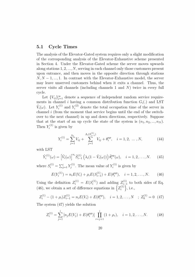
The analysis of the Elevator-Gated system requires only a slight modificationof the corresponding analysis of the Elevator-Exhaustive scheme presentedin Section 4. Under the Elevator-Gated scheme the server moves upwardsalong stations 1, 2, ..., N , serving in each channel only those customers presentupon entrance, and then moves in the opposite direction through stationsN,N − 1, ..., 1. In contrast with the Elevator-Exhaustive model, the servermay leave unserved customers behind when it exits a channel. Thus, theserver visits all channels (including channels 1 and N) twice in every fullcycle.
Let {Vij}∞j=1 denote a sequence of independent random service require-ments in channel i having a common distribution function Gi(.) and LST
Vi(ω). Let Y(1)i and Y
(2)i denote the total occupation time of the server in
channel i (from the moment that service begins until the end of the switch-over to the next channel) in up and down directions, respectively. Supposethat at the start of an up cycle the state of the system is (n1, n2, ..., nN).
Then Y(1)i is given by
Y(1)i =
ni∑j=1
Vij +
Ai(S(1)i−1)∑
j=1
Vij + θupi , i = 1, 2, ... , N, (44)
with LST
Y(1)i (ω) =
[Vi(ω)
]ni
S(1)i−1
(λi(1− Vi(ω))
)θupi (ω), i = 1, 2, . . . , N. (45)
where S(1)i =
∑ij=1 Y
(1)j . The mean value of Y
(1)i is given by
E(Y(1)i ) = niE(Vi) + ρiE(S
(1)i−1) + E(θupi ), i = 1, 2, . . . , N. (46)
Using the definition Z(1)i = E(S
(1)i ) and adding Z
(1)i−1 to both sides of Eq.
(46), we obtain a set of difference equations in{Z
(1)i
}, i.e.,
Z(1)i − (1 + ρi)Z
(1)i−1 = niE(Vi) + E(θupi ), i = 1, 2, . . . , N ; Z
(1)0 = 0 (47)
The system (47) yields the solution
Z(1)i =
i∑j=1
[njE(Vj) + E(θupi )]i∏
r=j+1
(1 + ρr), i = 1, 2, . . . , N. (48)
20

Thus, the mean value of the up cycle is
E(C1) = Z(1)N =
N∑j=1
[njE(Vj) + E(θupi )]N∏
r=j+1
(1 + ρr). (49)
Now,
Y(2)i =
Ai
(Y
(1)i +
∑N
r=i+1(Y
(1)r +Y
(2)r )
)∑j=1
Vij + θdowni−1 , i = 1, 2, ... , N (50)
with LST
Y(2)i (ω) =
E
exp
−λi (1− Vi(ω))Y (1)
i +N∑
r=i+1
(Y (1)r + Y (2)
r
) θdowni−1 (ω),
i = 1, 2, . . . , N. (51)
And mean value
E(Y(2)i ) = λiE(Vi)
E(Y(1)i ) +
N∑r=i+1
(E(Y (1)
r ) + E(Y (2)r )
)+ E(θdowni−1 ),
i = 1, 2, . . . , N. (52)
This leads to
Z(2)i − (1 + ρi)Z
(2)i+1 = ρi
N∑r=i
E(Y (1)r ) + E(θ
(down)i−1 ),
i = 1, 2, . . . , N ; Z(2)N = 0 (53)
with solution
Z(2)i =
N∑j=i
[ρj(Z
(1)N − Z
(1)j−1
)+ E(θdownj−1 )
] j−1∏r=i
(1 + ρr), i = 1, 2, . . . , N. (54)
The mean value for the down cycle is
E(C2) = Z(2)1 =
N∑j=1
[ρj(Z
(1)N − Z
(1)j−1
)+ E(θdownj−1 )
] j−1∏r=1
(1 + ρr), (55)
21

as if n(2)j = λj
(Z
(1)N − Z
(1)j−1
)is the number of customers at channel j at the
end of the up cycle.In order to derive explicit expressions for Y
(1)i and Y
(2)i , we note that
ni, the number of customers present in queue i at the beginning of an upcycle, is the number of customers that have arrived to channel i during thetime interval starting ¿From the moment the server has last entered channeli in its down direction, until the end of the entire down cycle. Therefore,ni = Ai
(∑ir=1 Y
(2)r
). Then,
Y(1)i =
Ai
(Y
(2)i +
∑i−1
r=1(Y
(2)r +Y
(1)r )
)∑j=1
Vij + θupi (i = 1, 2, ... , N) (56)
with LST
Y(1)i (ω) =
E
{exp
[−λi
(1− Vi(ω)
)(Y
(2)i +
i−1∑r=1
(Y (2)r + Y (1)
r
))]}θupi (ω),
i = 1, 2, . . . , N. (57)
And mean value
E(Y(1)i ) = λiE(Vi)
[E(Y
(2)i ) +
i−1∑r=1
(E(Y (2)
r ) + E(Y (1)r )
)]+ E(θupi ),
i = 1, 2, . . . , N. (58)
The total mean occupation time of the server at channel i is
E(Y(1)i )+E(Y
(2)i )
= ρi
N∑j=1,j 6=i
(E(Y
(1)j ) + E(Y
(2)j )
)+ E(Y
(1)i ) + E(Y
(2)i )
+E(θdowni−1 ) +E(θupi )
= ρiE(C) + E(θdowni−1 ) + E(θupi ), i = 1, 2, . . . , N. (59)
Substituting the expression for E(Y(1)i ) + E(Y
(2)i ) in Eq. (58) yields
E(Y(1)i ) = ρi
[i−1∑r=1
(E(θdownr−1 ) + E(θupr ) + ρrE(C)
)+ E(Y
(2)i )
]+ E(θupi ),
22

i = 1, 2, . . . , N. (60)
The same applies for Y(2)i (using Eq. (52)),
E(Y(2)i ) = ρi
N∑r=i+1
(E(θdownr−1 ) + E(θupr ) + ρrE(C)
)+ E(Y
(1)i )
+ E(θdowni−1 ),
i = 1, 2, . . . , N. (61)
Eqs. (60) and (61) yield a set of 2N equations in the 2N unknowns{Y
(1)i , Y
(2)i
},
whose solution is given by
E(Y(1)i ) =
1
1− ρ2i
{E(θupi ) + ρi
[i−1∑r=1
[E(θdownr−1 ) + E(θupr ) + ρrE(C)
]
+ρi
N∑r=i+1
[E(θupr ) + E(θdownr−1 ) + ρrE(C)
]+ E(θdowni−1 )
(62)
E(Y(2)i ) =
1
1− ρ2i
{E(θdowni−1 ) + ρi
[N−1∑r=i
[E(θdownr−1 ) + E(θupr ) + ρrE(C)
]
+ρi
[i−1∑r=1
[E(θupr ) + E(θdownr−1 ) + ρrE(C)
]]+ E(θupi )
]}(63)
The mean total cycle time, is derived by summing over the occupationtimes in Eq.(59) and again, as expected, is
E(C) =
∑Ni=1
[E(θdowni−1 ) + E(θupi )
]1−∑N
i=1 ρi(64)
The mean up and down cycles are now calculated by setting E(C1) =∑Ni=1E(Y
(1)i ) and E(C2) =
∑Ni=1E(Y
(2)i ).
5.2 Comparison between the up and down cycles
Similarly to the result obtained for the Elevator-Exhaustive case (Proposition4.1), we have,
Proposition 5.1 In the Elevator-Gated model, E(C1) = E(C2) wheneverθupi = θdownN−i and ρupi = ρdownN−i+1 (i = 1, . . . , N).
23

5.3 Mean Waiting Times
In any Gated service regime, the number of customers served during a visitof the server equals the number of customers present at the channel uponarrival. That is X i
i = Ti. Thus, employing Eq. (6) for the classical (cyclic)Gated regime we have
E(Wi|Cyclic Gated) =E[(X i
i )2]− E(X i
i )
2λiE(X ii )
(1 + ρi). (65)
Accordingly, we can use Eq. (65) to calculate separately E(Wi|up) andE(Wi|down) in the Elevator-Gated scheme. E(Wi) is then given by theweighted sum of E(Wi|up) and E(Wi|down), Eq. (31).
The number of customers found by the server at channel i at a polling in-stant to that channel in the up direction, X i
i (up), is the number of customersthat have arrived at that channel during the time interval starting from themoment the server has last entered the channel in the down direction, untilits first return in the up direction. That is,
X ii (up) = Ai
(Y
(2)i +
i−1∑r=1
(Y (2)r + Y (1)
r
))
Thus, the waiting time in the up direction is given by Eq.(65) with X ii (up)
replacing X ii . , In a similar manner, denoting by X i
i (down) the number ofcustomers found by the server at channel i when polled in the down direction,we write
X ii (down) = Ai
Y (1)i +
N∑r=i+1
(Y (1)r + Y (2)
r
)so that the waiting time in the down direction is given by substitutingX ii (down) in Eq. (65).
To complete the evaluation of E(Wi) we turn to calculate the terms E(X ii )
and E[(X i
i )2]
for both the up and down directions.
24

5.4 Generating Functions
Using the same definitions as in section 4.4, but with respect to the Elevator-Gated case, we write
F upi (z)
def= E
N∏j=1
zXj
i (up)j
, i = 1, . . . , N. (66)
The evolution of the state of the system in the up direction is described by
Xji+1(up) =
Xji (up) + Aj(θ
upi ) + Aj
(Vi(X
ii (up))
)j 6= i
Ai(θupi ) + Ai
(Vi(X
ii (up))
)j = i
(67)
where Vi(n) is the total time to serve n customers at channel i. Thus,
F upi+1(z) = E
N∏j=1
zXj
i+1(up)
j
= θupi
N∑j=1
λj(1− zj)
F upi
z1, z2, ..., zi−1, Vi
N∑j=1
λj(1− zj)
, zi+1, ..., zN
,i = 1, . . . , N − 1. (68)
For X i1(up),
Xj1(up) =
Xj
1(down) + Aj(V1(X
11 (down))
)j ≥ 2
A1
(V1(X
11 (down))
)j = 1
(69)
therefore,
F up1 (z) = F down
1
V1
N∑j=1
λj(1− zj)
, z2, ..., zN
(70)
The PGFs of the system-state in the down direction are similarly defined as
F downi (z)
def= E
N∏j=1
zXj
i (down)j
, i = 1, 2, . . . , N. (71)
25

and the evolution of the states
Xji−1(down) =
Xji (down) + Aj(θ
downi−1 ) + Aj
(Vi(X
ii (down))
)j 6= i
Ai(θdowni−1 ) + Ai
(Vi(X
ii (down))
)j = i
(72)
XjN(down) =
XjN(up) + AN
(VN(XN
N (up)))
j ≤ N − 1
AN(VN(XN
N (up)))
j = N
(73)It follows that
F downi−1 (z) = E
N∏j=1
zXj
i−1(down)
j
= θdowni−1
N∑j=1
λj(1− zj)
F downi
z1, ..., zi−1, Vi
N∑j=1
λj(1− zj)
, zi+1, ..., zN
,i = 2, . . . , N (74)
F downN (z) = F up
N
z1, z2, ..., zN−1, VN
N∑j=1
λj(1− zj)
(75)
Let E(Xji (up)) = fupi (j) =
∂Fupi (z)
∂zj
∣∣∣z=1
and E(Xji (down)) = fdowni (j) =
∂F downi (z)
∂zj
∣∣∣∣z=1
.
Taking derivatives of F upi (z) and F down
i (z), we get 2N2 equations in the2N2 unknowns fupi (j) and fdowni (j) , j = 1, 2, . . . , N , as follows
fupi+1(j) = fupi (j)+λj [E(θupi ) + fupi (i)E(Vi)] , 1 ≤ i ≤ N−1, i 6= j
fupj+1(j) = λj[E(θupj ) + fupj (j)E(Vj)
]fup1 (j) = fdown1 (j)+λjf
down1 (1)E(V1), j 6= 1
fup1 (1) = λ1fdown1 (1)E(V1)
(76)
fdowni−1 (j) = fdowni (j)+λj[E(θdowni−1 ) + fdowni (i)E(Vi)
], 2 ≤ i ≤ N, i 6= j
26

fdownj−1 (j) = λj[E(θdownj−1 ) + fdownj (j)E(Vj)
]fdownN (j) = fupN (j)+λjf
upN (N)E(VN), j 6= N
fdownN (N) = λNfupN (N)E(VN)
(77)The second moments of Xj
i (up) and Xji (down) are calculated with the aid
of the second derivatives. Define fupi (j, k) =∂2Fup
i (z)
∂zj∂zk
∣∣∣∣z=1
and fdowni (j, k) =
∂2F downi (z)
∂zj∂zk
∣∣∣∣z=1
, then,
E[X ii (up)
2]
= fupi (i, i) + fupi (i)
E[X ii (down)
2]
= fdowni (i, i) + fdowni (i) .
fupi (i, i) and fdowni (i, i) are obtained by solving 2N3 equations in the 2N3 vari-ables for fupi (j, k) and fupi (j, k), i, j, k = 1, . . . , N . For i = 1, 2, . . . , N − 1we use Eq. (68) to get
∂2F upi+1(z)
∂zj∂zk
∣∣∣∣∣z=1
=
[∂2θupi∂zj∂zk
F upi +
∂θupi∂zk× ∂F up
i
∂zj+∂θupi∂zj× ∂F up
i
∂zk+ θupi
∂2F upi
∂zj∂zk
]z=1
where
∂2θupi∂zj∂zk
=
λjλkE((θupi )2) j 6= k
λ2jE((θupi )2) j = k
∂2F upi (z)
∂zj∂zk=
fupi (i)λjλkE(V 2i ) + λkf
upi (i, j)E(Vi)
+λjfupi (i, k)E(Vi) + fupi (j, k)+
fupi (i, i)λjλk(E(Vi))2 j 6= k
fupi (i)λ2jE(V 2
i ) + 2λjfupi (i, j)E(Vi)+
fupi (j, j) + fupi (i, i)λ2j(E(Vi))
2 j = k
∂θupi∂zk× ∂F up
i
∂zj= λkE(θupi )fupi (j)
∂θupi∂zj× ∂F up
i
∂zk= λjE(θupi )fupi (k)
27

Similar equations are derived from Eq. (70). In the same manner we useEqs. (74) and (75) to derive the corresponding set of 2N3 equations in theunknowns fdowni (j, k).
By substituting the expressions for E(X ii (up)) and E
[X ii (up)
2]
in Eq.(65)
one calculates E(Wi|up). Using Eq. (65) again with respect to the downcycle, the corresponding expression for E(Wi|down) is obtained. Finally,E(Wi) is calculating via Eq. (31).
6 Elevator Globally-Quasi-Exhaustive Scheme
In this section we study the Elevator-polling, Globally-Quasi-Exhaustive ser-vice regime. We calculate expressions for the mean occupation time of theserver in each channel, and obtain explicit expressions for the mean durationof a cycle. Finally, we derive expressions for calculating the mean waitingtime of an arbitrary customer in the various queues, both in the up and downdirections, as well as in general.
6.1 Cycle Times
Suppose that when a cycle starts, the state of the system is L(1) = (L(1)1 , . . . , L
(1)N ).
Then as was described in the Introduction, under the Elevator-polling, Globally-Quasi-Exhaustive service regime the server moves along stations 1, 2, ..., N(up direction), staying at channel i for the duration of L
(1)i M/Gi/1-type
busy periods. That is, the server makes a ”global” decision at the start ofa cycle as to the sojourn time it is going to spend at each channel. At theend of the up cycle the globally new state of the system is observed, sayL(2) = (L
(2)1 , . . . , L
(2)N ), and the server moves in the opposite (down) direc-
tion, through stations N,N − 1, ..., 1, staying at channel i for the durationof L
(2)i busy periods.
This type of polling scheme is an extension of the cyclic polling Globally-Quasi-Exhaustive service discipline suggested by Boxma, Levy & Yechiali[1992], and discussed by Moskovitch [1992].
Considering for a moment the above mentioned cyclic Globally-Quasi-Exhaustive discipline, in which the server moves from channel to channelin a cyclic fashion. If θi is the switch-over time from channel i, then itis easily seen that the cycle duration is unchanged if we alter the order of
28

service of the channels or the order of the switching times. This followsfrom the fact that the number of busy periods that the server stays in eachchannel is determined apriory at the beginning of the cycle, and is thereforeindependent of any change in the order of visits to the channels. In particular,if θup ≡ ∑N−1
i=1 θupi =∑N−1i=1 θdowni ≡ θdown, then the cycle duration remains
unchanged if the channels are served in the order 1, 2, ..., N or N,N−1, ..., 1.Thus, the durations of the up cycle and the down cycle in the Elevator-polling, Globally-Quasi-Exhaustive model are the same, and the entire cycleduration is equal to the sum of two cyclic Globally-Quasi-Exhaustive cycleswith zero switch-over time from channel 1 to channel N .
Formally, to show the equality of the up and the down cycles we write
E{
exp (−ωC1) |L(1)}
= E
exp
−ωN−1∑i=1
θupi +N∑i=1
L(1)i∑
k=1
Bik
=N−1∏i=1
θupi (ω)N∏i=1
Bi(ω)L
(1)i = θup(ω)
N∏i=1
Bi(ω)L
(1)i .
Thus,
C1(ω) = E {exp(−ωC1)} = θup(ω)GL(1)
(B1(ω), B2(ω), . . . , BN(ω)
), (78)
where GL(1)(z) = E{∏N
i=1 zL
(1)i
i
}. Similarly,
C2(ω) = E {exp(−ωC2)} = θdown(ω)GL(2)
(B1(ω), B2(ω), . . . , BN(ω)
)(79)
Now, if θup = θdown then, probabilistically, L(1) = L(2) and C1 = C2 so that allcycles are (probabilisticly) the same and equal to the cycle duration, Cg, ofan equivalent cyclic Globally-Quasi-Exhaustive scheme with zero switch-overtime from channel 1 to channel N .
Hence, in order to find the cycle duration and the sojourn time of theserver at channel i in the Elevator-polling scheme, we first give a brief analysisof the cyclic Globally-Quasi-Exhaustive model: Let (L1, L2, ..., LN) be thestate-vector of the system at the beginning of a cycle, where Li denotes thenumber of customers present at channel i, then
E(Li) = λi
N∑j=1,j 6=i
E(Bj)E(Lj) +N∑j=1
E(θj)
, i = 1, 2, ..., N. (80)
29

where θi is the switch-over time required when moving from channel i to thenext channel. By adding λiE(Bi)E(Li) to both sides of Eq. (80) we have
E(Li) [1 + λiE(Bi)] = λi
N∑j=1
E(Bj)E(Lj) +N∑j=1
E(θj)
≡ λiE(Cg),
i = 1, 2, ..., N (81)
where Cg denotes the cycle time in the cyclic Globally-Quasi-Exhaustiveregime. Then,
E(Li) = λi(1− ρi)E(Cg) (82)
Let Yi denote the occupation time of the server at channel i calculated fromthe moment the server enters the channel until the end of the switch-overtime to the next channel, and let Ri be the total net service time in channeli. Then
E(Yi) = E(Ri) + E(θi) = E(Bi)E(Li) + E(θi) = ρiE(Cg) + E(θi),
i = 1, 2, ..., N, (83)
Clearly,
E(Cg) =N∑i=1
E(Yi) =N∑i=1
ρiE(Cg) +N∑i=1
E(θi) (84)
so that, as expected,
E(Cg) =
∑Ni=1E(θi)
1−∑Ni=1 ρi
(85)
Finally, setting C∗g as the cycle time in the cyclic Globally-Quasi-Exhaustiveregime with θN = 0, the mean of a full cycle in the Elevator scheme is
E(C) = E(C1) + E(C2) = 2E(C∗g ) =2∑N−1j=1 E(θj)
1−∑Nj=1 ρi
. (86)
6.2 Mean Waiting Times
As C1 = C2,E(Wi) = 0.5 [E(Wi|up) + E(Wi|down)] (87)
30

To obtain E(Wi|up) and E(Wi|down) we use Eq. (6) with the appropriateterms for X i
i and Ti. Clearly,
Ti(up) = L(1)i + Ai
(Mi(L
(1)i )
)where Mi(L) is the duration of L M/Gi/1− type busy periods all distributedas Bi. X
ii (up), the number of customers at station i at polling instant in the
up direction, equals L(1)i plus the number of arrivals to channel i ¿From the
beginning of the up cycle until the entrance time of the server. That is,
X ii (up) = L
(1)i + Ai
i−1∑j=1
Y(1)j
= L(1)i +
i−1∑j=1
(Ai(θ
upj ) + Ai
(Mj(L
(1)j )
))Hence,
E(Ti(up)) =E(L
(1)i )
1− ρi(88)
E((Ti(up)2) = E
[(L
(1)i )
2] (
1
1− ρi
)2
+E(L(1)i )
[λ2iV ar(Bi) +
ρi1− ρi
](89)
E(X ii (up)Ti(up)
)
= E
L(1)i +
i−1∑j=1
(Ai(θ
upj ) + Ai
(Mj(L
(1)j )
))(L(1)i + Ai
(Mi(L
(1)i )
))= E
[L(1)i
]2+ L
(1)i
(Ai(Mi(L
(1)i )
))+ L
(1)i
i−1∑j=1
Ai(θupj ) + L
(1)i
i−1∑j=1
Ai(Mj(L
(1)j )
)
+Ai(Mi(L
(1)i )
) i−1∑j=1
Ai(θupj ) + Ai
(Mi(L
(1)i )
) i−1∑j=1
Ai(Mj(L
(1)j )
)= E
[(L
(1)i )
2]+λiE(Bi)E
[(L
(1)i )
2]+λiE(L
(1)i )
i−1∑j=1
E(θupj )+λ2iE(L
(1)i )E(Bi)
i−1∑j=1
E(θupj )
+λii−1∑j=1
E(Bj)E(L(1)i L
(1)j ) + λ2
iE(Bi)i−1∑j=1
E(Bj)E(L(1)i L
(1)j )
31

Thus,
E(X ii (up)Ti(up)
)=E[(L
(1)i )
2]
1− ρi+λi
(1
1− ρi
)i−1∑j=1
[E(θupj )E(L
(1)i ) + E(L
(1)i L
(1)j )E(Bj)
](90)
Substituting results (88), (89) and (90) in Eq. (6), we obtain
E(Wi|up) =
E
[(L
(1)i )
2]
(1−ρi)2 + E(L
(1)i )
[λ2iV ar(Bi) + ρi
1−ρi
]− E(L
(1)i )
1−ρi
2λiE(L
(1)i )
1−ρi
(1+ρi)
+
E
[(L
(1)i )
2]
1−ρi+ λi
(1
1−ρi
)∑i−1j=1
[E(θupj )E(L
(1)i ) + E(L
(1)i L
(1)j )E(Bj)
]2λi
E(L(1)i )
1−ρi
−
E
[(L
(1)i )
2]
(1−ρi)2 + E(L
(1)i )
[λ2iV ar(Bi) + ρi
1−ρi
]2λi
E(L(1)i )
1−ρi
Summing the first and third terms of the above equation, we have
E(Wi|up) =ρiE
[(L
(1)i )
2]
+ E(L(1)i )(1− ρi) [ρi(1− ρi)λ2
iV ar(Bi) + ρ2i ]
2λi(1− ρi)E(L(1)i )
+E[(L
(1)i )
2]
+ λi∑i−1j=1
[E(θupj )E(L
(1)i ) + E(L
(1)i L
(1)j )E(Bj)
]2λiE(L
(1)i )
(91)
E(Wi|down) is derived similarly by using Eq.(6) with Ti(down) andX ii (down):
Ti(down) = L(2)i + Ai
(Mi(L
(2)i )
)and
X ii (down) = L
(2)i +Ai
N∑j=i+1
Y(2)j
= L(2)i +
N∑j=i+1
(Ai(θ
downj−1 ) + Ai(Mj(L
(2)j ))
)
32

¿From the discussion above, when θup = θdown, the number of customerspresent at the various channels at the beginning of an up cycle or a downcycle are probabilistically the same. Thus, denoting by L∗i , the number of cus-
tomers present at channel i at the beginning of cycle C∗g , E(L(1)i ) = E(L
(2)i ) =
E(L∗i ) and E[(L
(1)i )
2]
= E[(L
(2)i )
2]
= E[(L∗i )
2]. Therefore, the total wait-
ing time is given by substituting E(Wi|up) and E(Wi|down) in Eq. (87),
with L∗i replacing of L(1)i and L
(2)i . Suppressing the stars from all L∗i and C∗g ,
we write
E(Wi) =ρiE(L2
i ) + E(Li)(1− ρi) [ρi(1− ρi)λ2iV ar(Bi) + ρ2
i ]
2λi(1− ρi)E(Li)
+E(L2
i ) + λi∑i−1j=1
[E(θupj Li) + E(LjLi)E(Bj)
]4λiE(Li)
+E(L2
i ) + λi∑Nj=i+1
[E(θdownj−1 Li) + E(LjLi)E(Bj)
]4λiE(Li)
(92)
As
ELi
λiE N∑j=1,j 6=i
E(Bi)LiLj +i−1∑j=1
θupj Li +N∑
j=i+1
θdownj−1 Li
= E(L2i ),
we have,
E(Wi) =ρiE(L2
i ) + E(Li)(1− ρi) [ρi(1− ρi)λ2iV ar(Bi) + ρ2
i ]
2λi(1− ρi)E(Li)+
E(L2i )
2λiE(Li)(93)
To complete the evaluation of E(Wi) (as given by Eq.(93) ), it is just leftto obtain E(L2
i ).
6.3 Generating Functions
Let (L(1)1 , L
(1)2 , . . . , L
(1)N ) be the vector state of the system at the beginning of
an up cycle, and let (L(2)1 , L
(2)2 , . . . , L
(2)N ) be the system’s state at the beginning
of the following down cycle (or vica verca). Then,
E[zL
(2)1
1 , zL
(2)2
2 , . . . , zL
(2)N
N
∣∣∣∣L(1)1 , L
(1)2 , . . . , L
(1)N
]
33
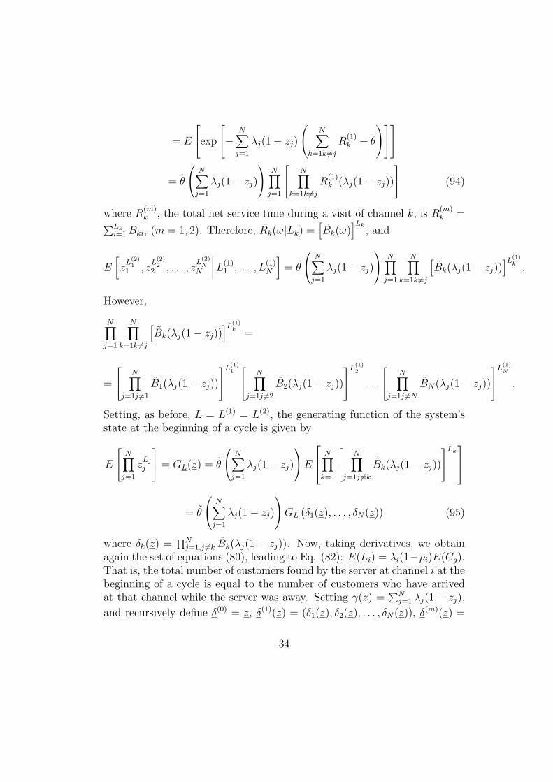
= E
exp
− N∑j=1
λj(1− zj)
N∑k=1k 6=j
R(1)k + θ
= θ
N∑j=1
λj(1− zj)
N∏j=1
N∏k=1k 6=j
R(1)k (λj(1− zj))
(94)
where R(m)k , the total net service time during a visit of channel k, is R
(m)k =∑Lk
i=1Bki, (m = 1, 2). Therefore, Rk(ω|Lk) =[Bk(ω)
]Lk, and
E[zL
(2)1
1 , zL
(2)2
2 , . . . , zL
(2)N
N
∣∣∣∣L(1)1 , . . . , L
(1)N
]= θ
N∑j=1
λj(1− zj)
N∏j=1
N∏k=1k 6=j
[Bk(λj(1− zj))
]L(1)k .
However,
N∏j=1
N∏k=1k 6=j
[Bk(λj(1− zj))
]L(1)k =
=
N∏j=1j 6=1
B1(λj(1− zj))
L(1)1 N∏j=1j 6=2
B2(λj(1− zj))
L(1)2
. . .
N∏j=1j 6=N
BN(λj(1− zj))
L(1)N
.
Setting, as before, L = L(1) = L(2), the generating function of the system’sstate at the beginning of a cycle is given by
E
N∏j=1
zLj
j
= GL(z) = θ
N∑j=1
λj(1− zj)
E N∏k=1
N∏j=1j 6=k
Bk(λj(1− zj))
Lk
= θ
N∑j=1
λj(1− zj)
GL (δ1(z), . . . , δN(z)) (95)
where δk(z) =∏Nj=1,j 6=k Bk(λj(1 − zj)). Now, taking derivatives, we obtain
again the set of equations (80), leading to Eq. (82): E(Li) = λi(1−ρi)E(Cg).That is, the total number of customers found by the server at channel i at thebeginning of a cycle is equal to the number of customers who have arrivedat that channel while the server was away. Setting γ(z) =
∑Nj=1 λj(1 − zj),
and recursively define δ(0) = z, δ(1)(z) = (δ1(z), δ2(z), . . . , δN(z)), δ(m)(z) =
34

δ(δ(m−1)(z)
)m = 2, 3, . . . , then, by iterating Eq. (95), we find, for every
M = 1, 2, . . .
GL(z) =M−1∏m=0
θ(γ(δ(m)(z)
))GL
(δ(M)(z)
)(96)
It can be shown, similarly to the calculation in Boxma, Levy & Yechiali[1992], that
limM→∞ δ(M)(z) = 1 and that the infinite product
∏∞m=0E
[e−γ(δ
(m)(z))θ]
con-
verges if ρ < 1. Hence,
GL(z) =∞∏m=0
θ(γ(δ(m)(z)
))(97)
The moments of the Lk’s can be now calculated in the regular manner.
7 Elevator-Polling, Globally-Gated Service Regime
The cyclic-polling, Globally-Gated (GG) service regime was introduced andstudied by Boxma, Levy & Yechiali [1992]. Under the cyclic GG procedure,at the start of each cycle, all customers present in the various queues aremarked, and those customers are the only ones to be served during thiscycle. Customers arriving in the middle of a cycle will be marked at thebeginning of the next cycle, and will be served during that cycle. Boxma,Levy & Yechiali derived the LST of the cycle time, C, and obtained explicitformulae for E(C) and E(C2). Not surprisingly, it was shown, once more,
that E(C) =[∑N
i=1E(θi)]/(1 − ρ), where θi is the switch-over time from
channel i to channel i + 1. They also derived the LST of Wi(cyclic), thewaiting time at queue i, and obtained an explicit formula for E (Wi (cyclic)),namely,
E (Wi (cyclic)) =
1 + 2i−1∑j=1
ρj + ρi
E(C2)
2E(C)+
i−1∑j=1
θj (98)
Furthermore, using Eq. (98), it was shown that
E (W1 (cyclic)) < E (W2 (cyclic)) < . . . < E (WN (cyclic)) .
Altman, Khamisy &Yechiali [1992] then studied the Elevator-polling withGG service regime. If θupi = θdowni , then, as in the Globally-Quasi-Exhaustive
35

case, all up and down cycles are probabilisticly the same. Utilizing this factand result (98) they showed that, for the Elevator-GG model, mean waitingtimes at all channels are the same, and equal to
E(W ) = (1 + ρ)E(C2)
2E(C)+E(θ)
2(99)
This is the only known nonsymetric polling scheme that achieves such a’fairness’ phenomenon.
7.1 Cycle Times and Generating functions
In this section we extend the analysis given by Altman, Khamisy & Yechiali[1992]. We will use the notation of previous sections.
The LSTs of the cycle times and the Generating Functions of L(1) andL(2) are related to each other as follows.
E{e−ωC1|L(1)
}= θup(ω)
N∏j=1
VL
(1)j
j (ω)
so that C1(ω) = θup(ω)GL(1)
(V1(ω), V2(ω), . . . , VN(ω)
). Also,
GL(1)(z) = EC2E
N∏j=1
ZL
(1)i
i |C2
= EC2
exp
−N∑j=1
λj(1− zj)C2
= C2
N∑j=1
λj(1− zj)
.Similarly, GL(2)(z) = C1
(∑Nj=1 λj(1− zj)
). Thus,
C1(ω) = θup(ω)C2
N∑j=1
λj(1− Vj(ω)
) , (100)
and
C2(ω) = θdown(ω)C1
N∑j=1
λj(1− Vj(ω)
) . (101)
Hence,C1(ω) = θup(ω)θdown (δ(ω)) C1
(δ(2)(ω)
)(102)
36

where, δ(ω) =∑Nj=1 λj
(1− Vj(ω)
), and δ(0)(ω) = ω; δ(m)(ω) = δ
(δ(m−1)(ω)
),
m = 1, 2, 3, . . . Iterating, and noticing that limm→∞ δ(m)(ω) = 0, so that
limm→∞ C1
(δ(m)(ω)
)= 1 (see Boxma, Levy & Yechiali [1992]), we finally
have
C1(ω) =∞∏m=0
θup(δ(2m)(ω)
)θdown
(δ(2m+1)(ω)
)(103)
Similarly,
C2(ω) =∞∏m=0
θdown(δ(2m)(ω)
)θup
(δ(2m+1)(ω)
)(104)
Now, if θup = θdown, then all up and down cycles are the same, and equal toC1. ¿From Eq. (103) and (104),
E(C1) = E(θup) + ρE(C2) and E(C2) = E(θdown) + ρE(C1).
Hence,
E(C1) =E(θup) + ρE(θdown)
1− ρ2and E(C2) =
E(θdown) + ρE(θup)
1− ρ2(105)
Clearly,
E(C) = E(C1) + E(C2) =E(θup) + E(θdown)
1− ρ(106)
It readily follows now that
E(L(1)i ) = λiE(C2), E(L
(2)i ) = λiE(C1) (107)
andE(Y
(1)i ) = E(L
(1)i )E(Vi) + E(θupi ) = ρiE(C2) + E(θupi ) (108)
E(Y(2)i ) = ρiE(C1) + E(θdowni ) (109)
7.2 Mean Waiting Times
We can use again Eqs. (6) and (31) to evaluate E(Wi). In order to calculateE(Wi|up) consider an arrival K to channel i during an up cycle. K will beserved only during the following down cycle. Hence, the number of customers,served at queue i during the server’s visit in which K is being served, is
37

Ti = Ai(C1), while the number of customers present when the server enters
channel i is X ii = Ti + Ai
(∑Nj=i+1 Y
(2)j
). Thus, as E(Ti) = λiE(C2) and
E(T 2i ) = λ2
iE(C21)+λiE(C1), the first term in (6) (when calculating E(Wi|up)
) is given byE(C2
1 )
2E(C1)(1 + ρ). (The probabilistic interruption of this term will
become apparent in the sequel). Now, the numerator of the second term of
(6) is given by E(Ai(C1)Ai
(∑Nj=i+1 Y
(2)j
)). Observe that Y
(2)j and C1 are
dependent since Y(2)j =
∑Aj(C1)j=1 Vjk + θdownj−1 .
We can complete the derivation in this manner, calculating similarlyE(Wi|down), but instead we choose to use a direct approach, applying argu-ments similar to those in Boxma, Levy & Yechiali [1992].
Consider again our customer K. His waiting time is composed of:
(i) The residual part of the up cycle, CR1 .
(ii) The service time of all customers who arrived at queues i+1, i+2, . . . , Nduring the up cycle in which K arrives.
(iii) The switch over times of the server on its way down from channel N tochannel i.
(iv) The service time of all customers who have arrived at channel i duringthe past part, CP
1 , of the up cycle in which K arrives.
Thus,
E(Wi|up) = E(CR1 ) +
N∑j=i+1
ρj[E(CP
1 ) + E(CR2 )]
+N−1∑j=i
E(θdownj ) + ρiE(CP1 )
(110)
Since E(CP1 ) = E(CR
1 ) =E(C2
1 )
2E(C1), we have (see also Altman, Khamisy &
Yechiali [1992]),
E(Wi|up) =
1 + 2N∑
j=i+1
ρj + ρi
E(CR1 ) +
N−1∑j=i
E(θdownj ) (111)
Similarly,
E(Wi|down) =
1 + 2i−1∑j=1
ρj + ρi
E(CR2 ) +
i−1∑j=1
E(θupj ) (112)
38

E(Wi) is readily obtained by substituting results (111), (112), (105) and(106) in Eq. (31). However, in order to complete the calculation we need toevaluate E(C2
1) and E(C22). By differentiating (100) and (101) we get
E(C21) = E
((θup)2
)+2ρE(θup)E(C2)+ρ2E(C2
2)+E(C2)N∑j=1
λjE(V 2j ) (113)
E(C22) = E
((θdown)
2)
+ 2ρE(θdown)E(C1) + ρ2E(C21) + E(C1)
N∑j=1
λjE(V 2j )
(114)E(C2
1) and E(C22) are easily derived from (113) and (114) so that E(CR
1 ) andE(CR
2 ) are readily calculated. Now, E(Wi) is completely determined.In the case where θ = θup = θdown, then C1 = C2, so that E(C1) =
E(C2) = E(θ)(1−ρ) and
E(C21) = E(C2
2) =1
1− ρ2
E(θ2) +2ρ[E(θ)]2
(1− ρ)+
(∑Nj=1 λjE(V 2
j ))E(θ)
(1− ρ)
(115)
Then, with E(CR1 ) = E(CR
2 ) we obtain
E(Wi|θup = θdown) = (1 + ρ)E(CR1 ) +
E(θ)
2(116)
That is, all mean waiting times are equal.
References
[1] E. Altman, A. Khamisy and U. Yechiali (1992), “On Elevator Pollingwith Globally-Gated Regime”, Queueing Systems 11, 85-90 .
[2] J.E. Baker and I. Rubin (1987), “Polling with a General-Service OrderTable”, IEEE Trans, on Communications 35, 283-288.
[3] O.J. Boxma, H. Levy and U. Yechiali (1992), “Reservation Schemes forEfficient Operation of Multiple-Queue Single-Server Systems”, Annalsof Operations Research 35, 187-208.
39

[4] O.J. Boxma, J.A. Weststrate and U. Yechiali (1993), “A Globally GatedPolling System with Server Interruptions and Applications to the Re-pairman Problem”, Prob. in Engineering and Informational Science,forthcoming.
[5] S. Browne and U. Yechiali (1989), “Dynamic Priority Rules for Cyclic-Type Queues”, Adv. Appl. Prob. 21, 432-450.
[6] S. Browne and U. Yechiali (1991), “Dynamic Scheduling in Single-ServerMulticlass Service Systems with Unit Buffers”, Naval Research Logistics38, 383-396.
[7] B.D. Bundary, J. Sztrik and R.B. Tapsir (1992), “A Heterogeneous ScanService Polling Model with Single-Message Buffer”, in Performance ofDistributed Systems and Integrated Communication, (T. Hasegawa, H.Takagi & Y. Tagahashi, Eds.), North Holland, 99-111.
[8] E.G. Coffman and M. Hofri (1982), “On The Expected Performance ofScanning Disks”, Siam J. Comput. 11, 60-70.
[9] Z. Moskovitch (1993), “Global-Type Polices in Polling Systems”, inpreparation.
[10] G.B. Swartz (1982), ”Analysis of a Scan Policy in a Gated Loop Sys-tem”, in Applied Probability-Computer Science: The Interface , Vol 2,(R.L. Disney & T.J. Ott, Eds.), Birkhauser, 241-252.
[11] H. Takagi (1986),Analysis of Polling Systems , MIT Press.
[12] H. Takagi and M. Murata (1986), ”Queueing Analysis of Scan-TypePolling Systems”, Computer Networking and Performance Evaluation,(T. Hasegawa, H. Takagi & Y. Takahashi, Eds.), North Holland, 199-211.
[13] H. Takagi (1990), “Queueing Analysis of Polling Models: An update”,in Stochastic Analysis of Computer and Communication Systems (H.Takagi, Ed.), North-Holland, 267-318.
[14] K.S. Watson (1984), “Performance Evaluation of Cyclic Service Strate-gies - a Survey”, in Performance ’84, (E. Gelenbe, Ed.), North-Holland, 521-533.
40
[15] U. Yechiali (1991), “Optimal Dynamic Control of Polling Systems”,in Queuing Performance and Control in ATM , (J. W. Cohen & C.D.Pack, Eds.), North-Holland, 205-396.
41