elim d diesel engine driven fruitland vacuum pump …
TRANSCRIPT

FM-EDJM-2016
Operation and Maintenance Instructions.
Please refer to the following documents to understand your Fruitland Diesel Engine driven vacuum
pump system,
Fruitland vacuum pump operation and maintenance manual included and available at
www.fruitlandmanufacturing.com
Deutz diesel engine operation and maintenance manual included and available at
www.fruitlandmanufacturing.com
Control Panel, EL240 operation and troubleshooting, included.
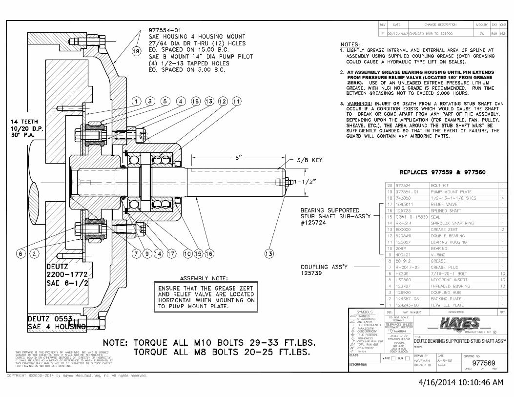
Stub Shaft, Hayes, drawing for parts and service instructions, included.
Fruitland Elim D system drawing and Bill of materials, included.
Fruitland Elim D vibration mount assembly and installation drawing, included.
Engine Start-up:
ELIM D DIESEL ENGINE DRIVEN FRUITLAND VACUUM PUMP SYSTEM

FM-EDJM-2016
Pump the primer button several times until it gets firmer. The primer bulb is located on the side of the
engine as shown in the picture above.
Please read the attached control panel operation manual to start the engine and information about
panel gauges and indicator lights.
Engine RPM:
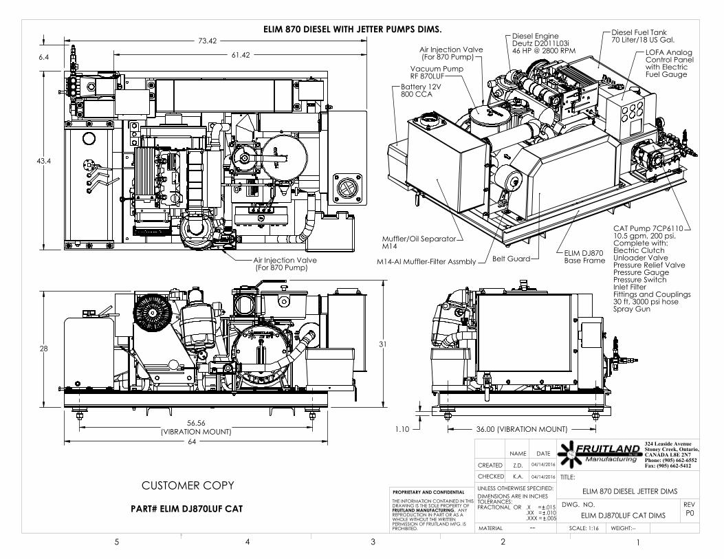
The diesel engine throttle is set to run between 2400 – 2600 rpm. The throttle lever is located next to oil
dip stick on the side of the engine.
The ratio between engine and pump drive pulleys is 2:1. Engine running at 2600 rpm will turn the
vacuum pump at 1300 rpm.
Maintenance:
Refer to diesel engine operational manual for Duetz diesel engine maintenance. Diesel engine
lubricating oil and maintenance schedule is listed on page 31 and 35 respectively of the engine manual.
Please read Fruitland vacuum pump operation and maintenance manual for vacuum pump
maintenance.
Belts: Every 2000 hours, it is recommended to remove the belt guard and inspect the belts and grease
the stub shaft bearing.
64
28 31
56.56(VIBRATION MOUNT)
43.4
61.42
73.42
6.4
Air Injection Valve (For 870 Pump)
36.00 (VIBRATION MOUNT) 1.10
Diesel EngineDeutz D2011L03i 46 HP @ 2800 RPM
Battery 12V800 CCA
Muffler/Oil SeparatorM14
Diesel Fuel Tank70 Liter/18 US Gal.
LOFA AnalogControl Panelwith ElectricFuel Gauge
Belt Guard
Vacuum PumpRF 870LUF
ELIM DJ870Base FrameM14-AI Muffler-Filter Assmbly
Air Injection Valve (For 870 Pump)
CAT Pump 7CP611010.5 gpm, 200 psi.Complete with:Electric ClutchUnloader ValvePressure Relief ValvePressure GaugePressure SwitchInlet FilterFittings and Couplings30 ft, 3000 psi hoseSpray Gun
PART# ELIM DJ870LUF CAT
CUSTOMER COPY
ELIM 870 DIESEL WITH JETTER PUMPS DIMS.
ELIM 870 DIESEL JETTER DIMS
K.A.
Z.D.
UNLESS OTHERWISE SPECIFIED:
SCALE: 1:16 WEIGHT:--
REVDWG. NO.
TITLE:
NAME DATE
CHECKED
CREATED
--MATERIAL
DIMENSIONS ARE IN INCHESTOLERANCES:FRACTIONAL OR .X = .015 .XX = .010 .XXX = .005
PROPRIETARY AND CONFIDENTIAL
THE INFORMATION CONTAINED IN THISDRAWING IS THE SOLE PROPERTY OFFRUITLAND MANUFACTURING. ANY REPRODUCTION IN PART OR AS A WHOLE WITHOUT THE WRITTEN PERMISSION OF FRUITLAND MFG. IS PROHIBITED.
5 4 3 2 1
324 Leaside Avenue Stoney Creek, Ontario, CANADA L8E 2N7Phone: (905) 662-6552 Fax: (905) 662-541204/14/2016
ELIM DJ870LUF CAT DIMS P0
04/14/2016
SHEET: 1 OF 4

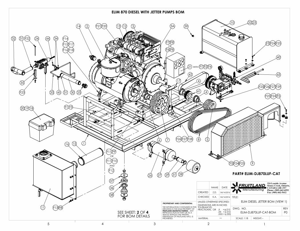
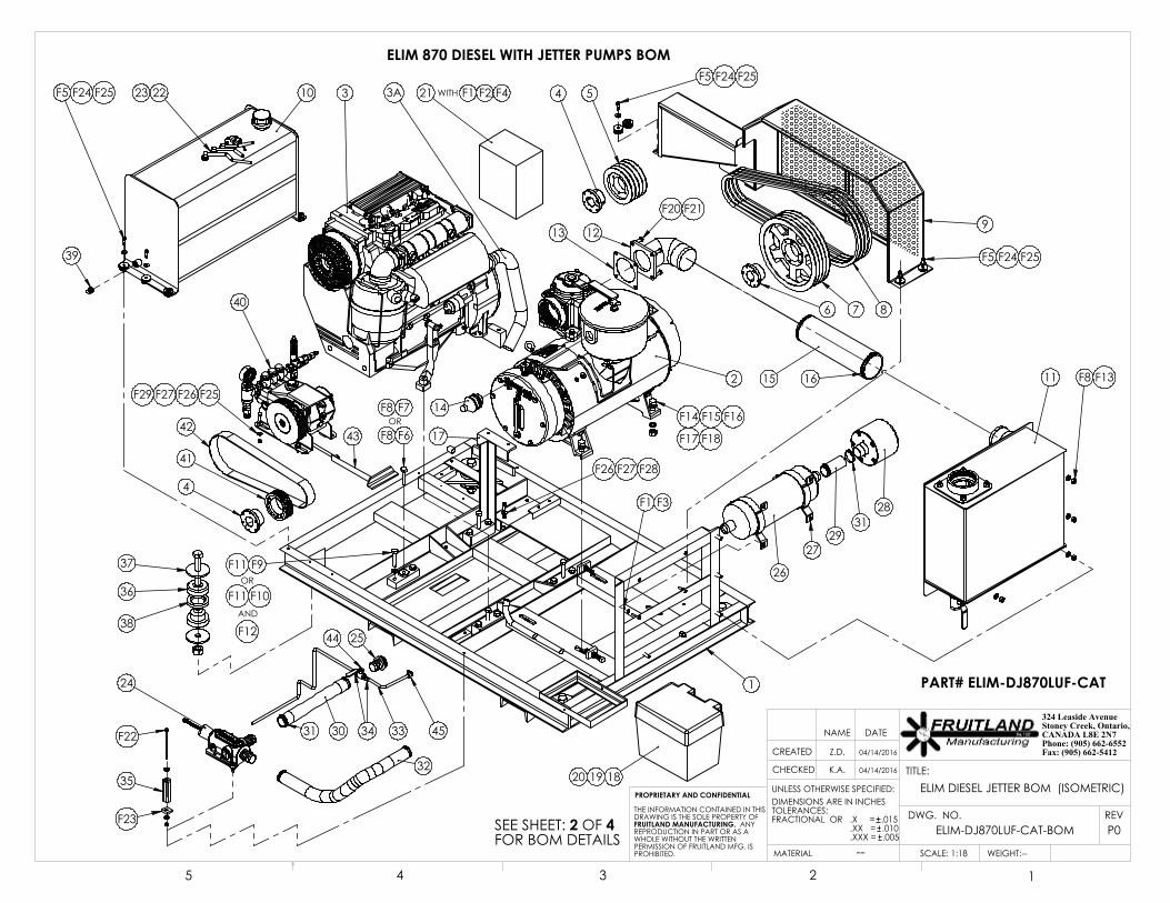
ELIM 870 DIESEL WITH JETTER PUMPS BOM
PART# ELIM-DJ870LUF-CAT
7 PART # DESCRIPTION QTY.1 EDJ-870-01C ELIM DJ870 BASE FRAME (DWG.# EDJ-870-01) 12 870LUF VACUUM PUMP 13 ENGINE-D2011L03I DEUTZ DIESEL ENGINE 1
3A ED-14-01 ELIM D MUFFLER EXTENTION 14 ED-12-A4 SK 1.5" BUSHING 25 RF500-38 6" SHEAVE 4 GROOVE B SECT. 16 SF42 TAPER PUMP BUSHING - 42mm BORE 17 5B12.4L SHEAVE 12.4 SF 4 GR. B SECT. 18 ED-870-A1 B70 V-BELT 49 EDJ-870-02A ELIM DJ870 BELT GUARD (DWG.# EDJ-870-02A) 110 EDF-14C DEISEL FUEL TANK (DWG.# EDF-J-14) 111 RF870-M14 MUFFLER M14 (DWG.# M14-BOM) 112 FL14 ELIM 870 4" FLANGE (DWG.# FL14) 113 RF870-65 DIVERTER GASKET FOR RF870 114 VB 1-1/2" VACUUM RELIEF VALVE 115 4" RUBBER HOSE MUF 4" RUBBER MUFFLER HOSE, 15.25" LG. 15.25"16 MAXI-CLAMP 4" HOSE CLAMP (MAXI-CLAMP) 217 EDJ-870-07 EDJ 870 CONTROL PANEL BRACKET (DWG.# ED-870-01) 118 ED-12-A5 BATTERY 119 BATTERY BOX BATTERY BOX 120 ED BATTERY CLAMP BATTERY HOLD DOWN CLAMP KIT 121 CONTROL PANEL 122 EDF-12-A11 5/16" I.D. DIESEL FUEL HOSE 2FT 323 EDF-12-A12 5/16" HOSE CLIP 5 24 RF870-AI AIR INJECTION VALVE (FOR 870 PUMP) 125 1.5" NPT-BRB BARB NIPPLE 1-1/2" NPT-1-1/2" HOSE (HEX) 126 M14-AI AIR INJECTION MUFFLER 127 M14-AI-B AIR INJECTION MUFFLER BRACKET 228 AI-870-F AIR FILTER 129 AI-870-FC 1.5" HOSE GOODYEAR EXTREMEFLEX, 4" LG 4"30 1.5" HOSE EXFL 1.5" HOSE GOODYEAR EXTREMEFLEX, 14" LG 14"31 1.5" HOSE CLAMP 1.5" HOSE CLAMP M8 52-55 632 1.5" HOSE EXFL 1.5" HOSE GOODYEAR EXTREMEFLEX, 27.5" LG. 27.5"33 3/8" TUBE 3/8" O.D. TUBE, 40" LG. 40"34 STRAIGHT 1/4" NPT TO 3/8" O.D. TUBE JIC 235 SPACER FOR AI VALVE (SQ 1 x 1 x 0.125 x 3.5 LG.) 236 ED-16-01 ED FRAME VIBRATION MOUNT (DWG# ED-870-VBM-INST) 437 ED-16-02 ED FRAME VIBRATION MOUNT REBOUND WASHER 838 ED-16-03 ED FRAME VIBRATION MOUNT SPACER 439 0.5" SQUARE PIPE PLUG 140 EDJ-7CP6110 CAT WATER PUMP, 10.5 GPM@2000 PSI 141 EDJ-14-10 POLY-V-L8 PULLEY 142 EDJ-14-11 POLY V BELT 530, 8 GROOVE SECTION 143 EDJ-14-09 ED-J JETTER PUMP BELT TIGHTENER (DWG.# EDJ-870-01) 144 1/4" BALL VALVE 145 ELBOW 90 1/4" NPT TO 3/8" O.D. TUBE JIC 1
FASTENEF1 5/16" WASHER 5/16" Z.P. FLAT WASHER 6F2 5/16" X .1" HEX BOLT 5/15" NC NYLOCK HEX NUT 2F3 5/16" NUTS 5/16" Z.P. HEX NUT 4F4 5/16" X .1" HEX BOLT 5/16" NC x 1" LG. Z.P. HEX BOLT 2F5 3/8" x 0.625" WITH 5/16"-18 NC SHOULDER BOLT 12F6 1/2" X 3"HEX BOLT 1/2" UNC x 3" LG. Z.P. HEX BOLT 3F7 1/2" X 4"LG. HEX BOLT 1/2" UNC x 4" LG. Z.P. HEX BOLT 1F8 1/2 L/W 1/2" Z.P. LOCK WASHER 9F9 1/2 X 2-1/2" 1/2" NC x 2-1/2" LG. Z.P. HEX BOLT 2F10 1/2 X 3" 1/2" NC x 3" LG. Z.P. HEX BOLT 6F11 1/2" FLAT WASHER 1/2" Z.P. FLAT WASHER 8F12 1/2" NY-LOCK NUTS ZP 1/2" Z.P. NYLOCK HEX NUT 8F13 1/2" NUTS 1/2" NC Z.P. HEX NUT 5F14 5/8" NUT 5/8" NC Z.P. HEX NUT 4F15 5/8"X2-1/4" HEX HEAD 5/8" NC x 2-1/4" LG. Z.P. HEX BOLT 4F16 5/8" F/W-USS 5/8" Z.P. FLAT WASHER - LARGE 4F17 5/8" L/W 5/8" Z.P. LOCK WASHER 4F18 5/8" F/W-SAE 5/8" Z.P. FLAT WASHER - SMALL 4F20 RF500-67A 10mm HEX HEAD BOLT, 10x1.5x30 4F21 RF120-94A 10mm LOCK WASHER 4F22 5/16" NCx5.5" HEX HEAD w NUT & W (for air injection block) 2
F23 5/16" SCREW SIZE TAPER (LEVELIN) WASHER 1F24 ED-16-03 ED FRAME RUBBER WASHER 48F25 3/8"F/W-USS 3/8" Z.P. FLAT WASHER-LARGE 24F26 3/8" NC HEX HEAD BOLT, 1.25" LG. 6F27 3/8" Z.P. NYLOCK HEX NUT 6F28 3/8"F/W-SAE 3/8" Z.P. FLAT WASHER-SMALL 2F29 3/8" SCREW SIZE TAPER (LEVELIN) WASHER 2
P0
ELIM DIESEL JETTER BOM K.A.
Z.D.
UNLESS OTHERWISE SPECIFIED:
SCALE: 1:18 WEIGHT:--
REVDWG. NO.
TITLE:
NAME DATE
CHECKED
CREATED
--MATERIAL
DIMENSIONS ARE IN INCHESTOLERANCES:FRACTIONAL OR .X = .015 .XX = .010 .XXX = .005
PROPRIETARY AND CONFIDENTIAL
THE INFORMATION CONTAINED IN THISDRAWING IS THE SOLE PROPERTY OFFRUITLAND MANUFACTURING. ANY REPRODUCTION IN PART OR AS A WHOLE WITHOUT THE WRITTEN PERMISSION OF FRUITLAND MFG. IS PROHIBITED.
5 4 3 2 1
324 Leaside Avenue Stoney Creek, Ontario, CANADA L8E 2N7Phone: (905) 662-6552 Fax: (905) 662-541204/14/2016
ELIM-DJ870LUF-CAT-BOM
04/14/2016
SHEET: 2 OF 4
11
9
2
1516
3
21
13
16 7
4
58
OR
14 12
24
OR
WITH
26
1820
F7 F8
F12
F8F13
F16
F15
F14
F18
F17
F20F21
F11 F9
AND
F11 F10
30
32 31 F22
25
2827 29
F6 F8
F3F1
SEE SHEET: 2 OF 4FOR BOM DETAILS
33
31
3145
35
F23
3A
41
42
40
417
F28F27F26
10 22 23
F5 F24 F25
F5 F24 F25
43
37
36
38
39
F25 F26 F27 F29
F1 F2 F4
19
F5F24F25
44 34
ELIM 870 DIESEL WITH JETTER PUMPS BOM
PART# ELIM-DJ870LUF-CAT
P0
K.A.
Z.D.
UNLESS OTHERWISE SPECIFIED:
SCALE: 1:18 WEIGHT:--
REVDWG. NO.
TITLE:
NAME DATE
CHECKED
CREATED
--MATERIAL
DIMENSIONS ARE IN INCHESTOLERANCES:FRACTIONAL OR .X = .015 .XX = .010 .XXX = .005
PROPRIETARY AND CONFIDENTIAL
THE INFORMATION CONTAINED IN THISDRAWING IS THE SOLE PROPERTY OFFRUITLAND MANUFACTURING. ANY REPRODUCTION IN PART OR AS A WHOLE WITHOUT THE WRITTEN PERMISSION OF FRUITLAND MFG. IS PROHIBITED.
5 4 3 2 1
324 Leaside Avenue Stoney Creek, Ontario, CANADA L8E 2N7Phone: (905) 662-6552 Fax: (905) 662-5412
04/14/2016
SHEET: 3 OF 4
04/14/2016
ELIM-DJ870LUF-CAT-BOM
ELIM DIESEL JETTER BOM (VIEW 1)
11
9
2 15 16
3 21
13
1
6 7
4 5
8
OR14
12
24
OR
WITH
26
181920
F7F8
F12
F8 F13
F14 F15 F16
F17 F18
F20 F21
F9F11
AND
F10F11
30
32
31F22
25
28
2729
F6F8
F1 F3
SEE SHEET: 2 OF 4FOR BOM DETAILS
33 45
35
F23
31
3A
40
41
42
4
17
F26 F27 F28
F25F26F27F29
F5 F24 F25 2223 10
F5 F24 F25
43
37
36
38
39
F1 F2 F4F5 F24 F25
44
34
ELIM 870 DIESEL WITH JETTER PUMPS BOM
PART# ELIM-DJ870LUF-CAT
P0
K.A.
Z.D.
UNLESS OTHERWISE SPECIFIED:
SCALE: 1:18 WEIGHT:--
REVDWG. NO.
TITLE:
NAME DATE
CHECKED
CREATED
--MATERIAL
DIMENSIONS ARE IN INCHESTOLERANCES:FRACTIONAL OR .X = .015 .XX = .010 .XXX = .005
PROPRIETARY AND CONFIDENTIAL
THE INFORMATION CONTAINED IN THISDRAWING IS THE SOLE PROPERTY OFFRUITLAND MANUFACTURING. ANY REPRODUCTION IN PART OR AS A WHOLE WITHOUT THE WRITTEN PERMISSION OF FRUITLAND MFG. IS PROHIBITED.
5 4 3 2 1
324 Leaside Avenue Stoney Creek, Ontario, CANADA L8E 2N7Phone: (905) 662-6552 Fax: (905) 662-5412
04/14/2016
SHEET: 4 OF 4
04/14/2016
ELIM-DJ870LUF-CAT-BOM
ELIM DIESEL JETTER BOM (ISOMETRIC)

A
A
ELIM D 870 FRAME
SUPPORTING MEMBER
A-A
1.00
REBOUND WASHERPART # ED-16-02
SPACERPART # ED-870-03
OPTIONAL REBOUND WASHER(DEPENDS ON THE CUSTOMER'SFRAME)
TWO-PIECEMOUNTSPART # ED-16-01
7/8"-14NF x 5.5" LENGTH GRADE 8 BOLT
FRUITLAND ELIM D870 VIBRATION ISOLATION MOUNT INSTALLATION
Ø7/8"-14 NF NYLOK NUT
ELIM D870 FRAME
CUSTOMERFRAME
P0
ELIM D870 VIBRATION ISOLATION MOUNT INSTALLATION
Z.D.
UNLESS OTHERWISE SPECIFIED:
SCALE: 1:12 WEIGHT:--
REVDWG. NO.
TITLE:
NAME DATE
CHECKED
CREATED
--MATERIAL
DIMENSIONS ARE IN INCHESTOLERANCES:FRACTIONAL OR .X = .015 .XX = .010 .XXX = .005
PROPRIETARY AND CONFIDENTIAL
THE INFORMATION CONTAINED IN THISDRAWING IS THE SOLE PROPERTY OFFRUITLAND MANUFACTURING. ANY REPRODUCTION IN PART OR AS A WHOLE WITHOUT THE WRITTEN PERMISSION OF FRUITLAND MFG. IS PROHIBITED.
5 4 3 2 1
324 Leaside Avenue Stoney Creek, Ontario, CANADA L8E 2N7Phone: (905) 662-6552 Fax: (905) 662-541207/23/2015
ED-870-VBM-INST.
K.A 07/23/2015
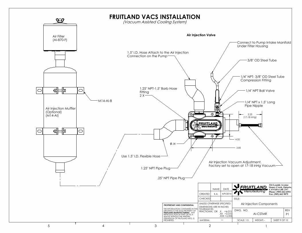
M14-AI-B
.38
3.85
4.00
2.25(17-18 inHg)
Air Injection Vacuum Adjustment.Factory set to open at 17-18 inHg Vacuum
3/8" OD Steel Tube
1.25" NPT-1.5" Barb HoseFitting2 X
1.5" I.D. Hose Attach to the Air Injection Connection on the Pump
Connect to Pump Intake ManifoldUnder Filter Housing
Use 1.5" I.D. Flexible Hose
1/4" NPT- 3/8" OD Steel TubeCompression Fitting
1/4" NPT Ball Valve
1/4" NPT x 1.5" Long Pipe Nipple
1.25" NPT Pipe Plug
.25" NPT Pipe Plug
Air Filter(AI-870-F)
Air Injection Muffler(Optional)(M14-AI)
Air Injection Valve
FRUITLAND VACS INSTALLATION(Vacuum Assisted Cooling System)
P1
Air Injection Components
SHEET 9 OF 10
K.A.
UNLESS OTHERWISE SPECIFIED:
SCALE: 1:5 WEIGHT:--
REVDWG. NO.
TITLE:
NAME DATE
CHECKED
CREATED
--MATERIAL
DIMENSIONS ARE IN INCHESTOLERANCES:FRACTIONAL OR .X = .015 .XX = .010 .XXX = .005
PROPRIETARY AND CONFIDENTIAL
THE INFORMATION CONTAINED IN THISDRAWING IS THE SOLE PROPERTY OFFRUITLAND MANUFACTURING. ANY REPRODUCTION IN PART OR AS A WHOLE WITHOUT THE WRITTEN PERMISSION OF FRUITLAND MFG. IS PROHIBITED.
5 4 3 2 1
324 Leaside Avenue Stoney Creek, Ontario, CANADA L8E 2N7Phone: (905) 662-6552 Fax: (905) 662 98754/9/2014
AI-CSTMR
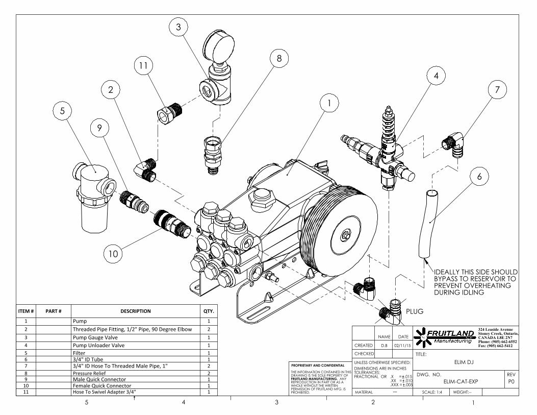
1
3
4
5
6
8
2
10
9
11
7
PLUG
IDEALLY THIS SIDE SHOULDBYPASS TO RESERVOIR TO PREVENT OVERHEATING DURING IDLING
ITEM # PART # DESCRIPTION QTY.
1 Pump 12 Threaded Pipe Fitting, 1/2" Pipe, 90 Degree Elbow 23 Pump Gauge Valve 14 Pump Unloader Valve 15 Filter 16 3/4" ID Tube 17 3/4" ID Hose To Threaded Male Pipe, 1" 28 Pressure Relief 29 Male Quick Connector 1
10 Female Quick Connector 111 Hose To Swivel Adapter 3/4" 1
P0
ELIM DJ
D.B
UNLESS OTHERWISE SPECIFIED:
SCALE: 1:4 WEIGHT:--
REVDWG. NO.
TITLE:
NAME DATE
CHECKED
CREATED
--MATERIAL
DIMENSIONS ARE IN INCHESTOLERANCES:FRACTIONAL OR .X = .015 .XX = .010 .XXX = .005
PROPRIETARY AND CONFIDENTIAL
THE INFORMATION CONTAINED IN THISDRAWING IS THE SOLE PROPERTY OFFRUITLAND MANUFACTURING. ANY REPRODUCTION IN PART OR AS A WHOLE WITHOUT THE WRITTEN PERMISSION OF FRUITLAND MFG. IS PROHIBITED.
5 4 3 2 1
324 Leaside Avenue Stoney Creek, Ontario, CANADA L8E 2N7Phone: (905) 662-6552 Fax: (905) 662-5412
ELIM-CAT-EXP
02/11/15

EL240™ Panel Operation
and Troubleshooting
463-3000-05 Rev B. 23-Sep-2013 1 © 2006-2013 LOFA Industries, Inc. All rights reserved.
LOFA, the LOFA logo, CANplus and EL240 are trademarks of LOFA Industries, Inc. All rights reserved.
Windows is a registered trademark of Microsoft Corporation.
Introduction
This document provides general information on LOFA™ EL240 panel operation and troubleshooting. EL240
control panels are a flexible platform for diesel engine control, monitoring, and protection, featuring LOFA’s
powerful First Fault Diagnostics (FFD). After pinpointing the initial failure, FFD stores it in memory and alerts
the end user via a single bright LED. FFD monitors battery charge, low oil pressure, high temperature and up
to two additional contact closure inputs. The microprocessor-based solid-state design uses high-power
semiconductors instead of outdated electromechanical relays to ensure reliable high-current switching.
The EL240 can be factory configured with specific preheat and afterglow requirements. Alternately preheat
can be factory configured for indication from external preheat control. If preheat is not required, this output
can function as an alarm.
All standard panels include feature a 12 inch wiring harness terminating into a sealed weather proof plug. This
robust universal wiring connection performs well in harsh environments and allows interchanging a number
of different panels and harnesses. This design allows for simplified installation as well as a flexible means to
incorporate custom plug-and-play engine wiring harnesses and standard harness extension
Note
The engine harness is not included with the panel.
A number of standard engine harnesses are available or
LOFA can develop a custom harness for you exact needs.
Generic harnesses in various lengths are available for field customization.
Warning!
When replacement parts are required, LOFA Industries recommends using replacement parts
supplied by LOFA or parts with equivalent specifications.
Failure to heed this warning can lead to premature failure,
product damage, personal injury or death.

EL240 Panel Operation and Troubleshooting
2 463-3000-05 Rev B. 23-Sep-2013
Important Safety Information The warnings in this publication are not all inclusive.
LOFA Industries cannot anticipate every potential hazard.
Appropriate safety rules and precautions should be followed with any
tool, work method or operating procedure.
Improper procedures, tools and materials may cause
damage or make the equipment unsafe to operate.
Only persons with appropriate training, skills and tools
should perform these functions.
Improper operation, maintenance or repair of this product can be
dangerous and may result in injury or death.
Do not operate or perform any maintenance or repair on this product until all operation,
maintenance and repair information is read and understood.
The information, specifications, and illustrations in this publication are based on information
available at the time of publication.
All items are subject to change at any time without notice.
EL240 Panel Operation and Troubleshooting
463-3000-05 Rev B. 23-Sep-2013 3
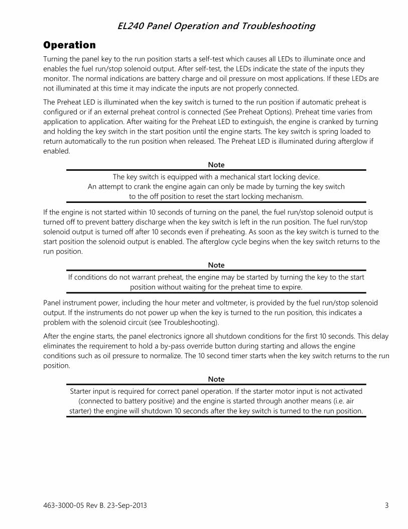
Operation
Turning the panel key to the run position starts a self-test which causes all LEDs to illuminate once and
enables the fuel run/stop solenoid output. After self-test, the LEDs indicate the state of the inputs they
monitor. The normal indications are battery charge and oil pressure on most applications. If these LEDs are
not illuminated at this time it may indicate the inputs are not properly connected.
The Preheat LED is illuminated when the key switch is turned to the run position if automatic preheat is
configured or if an external preheat control is connected (See Preheat Options). Preheat time varies from
application to application. After waiting for the Preheat LED to extinguish, the engine is cranked by turning
and holding the key switch in the start position until the engine starts. The key switch is spring loaded to
return automatically to the run position when released. The Preheat LED is illuminated during afterglow if
enabled.
Note
The key switch is equipped with a mechanical start locking device.
An attempt to crank the engine again can only be made by turning the key switch
to the off position to reset the start locking mechanism.
If the engine is not started within 10 seconds of turning on the panel, the fuel run/stop solenoid output is
turned off to prevent battery discharge when the key switch is left in the run position. The fuel run/stop
solenoid output is turned off after 10 seconds even if preheating. As soon as the key switch is turned to the
start position the solenoid output is enabled. The afterglow cycle begins when the key switch returns to the
run position.
Note
If conditions do not warrant preheat, the engine may be started by turning the key to the start
position without waiting for the preheat time to expire.
Panel instrument power, including the hour meter and voltmeter, is provided by the fuel run/stop solenoid
output. If the instruments do not power up when the key is turned to the run position, this indicates a
problem with the solenoid circuit (see Troubleshooting).
After the engine starts, the panel electronics ignore all shutdown conditions for the first 10 seconds. This delay
eliminates the requirement to hold a by-pass override button during starting and allows the engine
conditions such as oil pressure to normalize. The 10 second timer starts when the key switch returns to the run
position.
Note
Starter input is required for correct panel operation. If the starter motor input is not activated
(connected to battery positive) and the engine is started through another means (i.e. air
starter) the engine will shutdown 10 seconds after the key switch is turned to the run position.

EL240 Panel Operation and Troubleshooting
4 463-3000-05 Rev B. 23-Sep-2013
To prevent unintentional engine shutdowns caused by intermittent conditions (i.e., pressure spikes, coolant
movement) the panel requires a constant 1 second fault input to cause engine shutdown.
Warning!
When used in combination with mechanical float type switches
engine vibrations may prevent constant contact closure.
The panel is factory configured to shutdown with
no delay for the auxiliary shutdown inputs.
Preheat Options
Preheat Output
Preheat is a 750 mA output for control of an external power relay with predetermined preheat and afterglow
times. A relay should be selected with appropriate amperage capacity for the installed cold starting aid
(glowplug, intake air heater, etc.). Applications using multiple cold starting aids may require multiple relays.
This output provides low side (ground) preheat control.
Note
Consult engine documentation when selecting cold starting aid,
power relay and heating specifications.
Preheat Indication Input
This optional factory configuration, the preheat LED provides indication for an external preheat control. This
input accepts high side (battery positive) control to indicate preheat.
Indicators
Battery LED (Red)
A solidly illuminated Battery LED indicates a battery charge failure. A battery charge failure may be caused by
a faulty alternator, broken drive belt or the alternator not excited. A battery voltage reading of approximately
14 volts on 12 volt systems (28 volts on 24 volt systems) while the engine is running indicates the battery is
charging properly. Irregular blinking of the Battery LED may indicate a failing charge circuit. The panel can be
factory configured for battery charge failure to indicate only.
Oil Pressure LED (Red)
A solidly illuminated Oil Pressure LED indicates low oil pressure failure. The panel typically senses low oil
pressure from a ground contact switch on the engine. When a sender/switch combination is used on the
engine, the marking WK generally indicates the switch terminal. This input typically expects a normally closed
switch (ground contact when oil pressure is low). A defective switch or shorting the shutdown input to ground
can cause low pressure fault indication. Additionally, when using sender/switch combinations, swapping the
WK and G terminal can cause unintended shutdowns. The panel can be factory configured for oil pressure
failure to indicate only.

EL240 Panel Operation and Troubleshooting
463-3000-05 Rev B. 23-Sep-2013 5
Warning!
Low oil pressure is not an indication of low oil level.
For best possible protection LOFA recommends using
our solid-state oil level shutdown switch.
Note
Most shutdown switches are grounded through the switch body.
Do not use insulating sealant (i.e. Teflon tape) when installing switches.
Temperature LED (Red)
A solidly illuminated Temperature LED indicates high engine temperature failure. The panel typically senses
high temperature from a ground contact switch on the engine. When a sender/switch combination is used on
the engine, the marking WK or W generally indicates the switch terminal. This input typically expects a
normally open switch (ground contact when engine temperature is too high). A defective switch or shorting
the shutdown input to ground can cause over temperature fault indication. Additionally, when using
sender/switch combinations, swapping the WK or W and G terminal can cause unintended shutdowns. The
panel can be factory configured for temperature failure to indicate only.
Warning!
If the temperature switch is not in contact with coolant due to
coolant loss the engine is not protected from overheating.
For best possible protection, LOFA recommends using
our solid-state coolant level shutdown switch.
Note
Most shutdown switches are grounded through the switch body.
Do not use insulating sealant (i.e. Teflon tape) when installing switches.
Some thermostat housings are composites and do not provide ground for the switch.
AUX 1 LED (Red)
A solidly illuminated AUX 1 LED indicates auxiliary 1 failure (i.e., coolant level, oil level, belt breakage, hydraulic
pressure, etc.). The panel typically senses failure using a ground contact switch. Auxiliary inputs are equipment
specific and determined by the equipment manufacturer. A defective switch or shorting the shutdown input
to ground can cause fault indications. The panel can be factory configured for auxiliary 1 failure to indicate
only.
AUX 2 LED (Red)
A solidly illuminated AUX 2 LED indicates auxiliary 2 fault (i.e., air flow restriction, fuel level, etc.). The panel
typically senses failure using a ground contact switch. Auxiliary inputs are equipment specific and determined
by the equipment manufacturer. A defective switch or shorting the shutdown input to ground can cause fault
indications. The panel can be factory configured auxiliary 2 for shutdown.

EL240 Panel Operation and Troubleshooting
6 463-3000-05 Rev B. 23-Sep-2013
Warning
When used in combination with mechanical float type switches
engine vibrations may prevent constant contact closure. The panel is factory configured to
shutdown with no delay for the auxiliary shutdown inputs.
Preheat LED (Red)
A solidly illuminated Preheat LED is the panel preheat indication. When the LED extinguishes the preheat
period is complete and the engine may be cranked. The LED illuminates again to indicate afterglow.

EL240 Panel Operation and Troubleshooting
463-3000-05 Rev B. 23-Sep-2013 7
Gauges
Voltmeter
The voltmeter is connected to the fuel run/stop solenoid output. If the voltmeter does not indicate in the run
position, this indicates a problem with the solenoid circuit. A battery voltage reading of approximately 14 volts
on 12 volt systems (28 volts on 24 volt systems) while the engine is running indicates the battery is charging
properly.
Tachometer
The tachometer indicates engine RPM using a frequency signal derived from the engine. This signal may be
provided by an alternator frequency tap, proximity switch. An optional amplifier/divider can be added for use
with a magnetic pickup.
Note
If the alternator is not excited (not charging),
no frequency is generated and the tachometer will indicate 0 RPM.
The tachometer must be calibrated to accurately indicate RPM (see Tachometer Calibration Instructions for
details).
Oil Pressure Gauge
The gauge measures oil pressure with a resistance sender on the engine referenced to ground. When a
sender/switch combination is used on the engine, the marking G generally indicates the gauge terminal. The
gauge expects a low resistance for low pressure and a higher resistance for higher pressure. If a powered
gauge is not connected to the sender, the gauge will read full scale (pegged). A defective sender or shorting
the gauge input to ground will cause the gauge to read no pressure. When using sender/switch
combinations, swapping the WK and G terminal prevents the gauge from working and may cause unintended
shutdowns.
Warning!
Low oil pressure is an indication of engine wear,
not an accurate indication of low oil level.
Note
Senders and gauges must be matched to indicate correctly.
Most senders are grounded through the sender body.
Do not use insulating sealant (i.e. Teflon tape) when installing senders.
Temperature Gauge
The gauge measures engine temperature with a resistance sender on the engine referenced to ground. When
a sender/switch combination is used on the engine, the marking G generally indicates the gauge terminal.
The gauge expects a high resistance for low temperatures and a lower resistance for higher temperatures. If
the gauge is not connected to the sender, the will be on read the minimum reading. A defective sender or
shorting the gauge input to ground will cause the gauge to read full scale (pegged). When using
sender/switch combinations, swapping the WK and G terminal prevents the gauge from working and may
cause unintended shutdowns.
EL240 Panel Operation and Troubleshooting
8 463-3000-05 Rev B. 23-Sep-2013
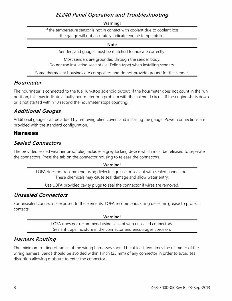
Warning!
If the temperature sensor is not in contact with coolant due to coolant loss
the gauge will not accurately indicate engine temperature.
Note
Senders and gauges must be matched to indicate correctly.
Most senders are grounded through the sender body.
Do not use insulating sealant (i.e. Teflon tape) when installing senders.
Some thermostat housings are composites and do not provide ground for the sender.
Hourmeter
The hourmeter is connected to the fuel run/stop solenoid output. If the hourmeter does not count in the run
position, this may indicate a faulty hourmeter or a problem with the solenoid circuit. If the engine shuts down
or is not started within 10 second the hourmeter stops counting.
Additional Gauges
Additional gauges can be added by removing blind covers and installing the gauge. Power connections are
provided with the standard configuration.
Harness
Sealed Connectors
The provided sealed weather proof plug includes a grey locking device which must be released to separate
the connectors. Press the tab on the connector housing to release the connectors.
Warning!
LOFA does not recommend using dielectric grease or sealant with sealed connectors.
These chemicals may cause seal damage and allow water entry.
Use LOFA provided cavity plugs to seal the connector if wires are removed.
Unsealed Connectors
For unsealed connectors exposed to the elements, LOFA recommends using dielectric grease to protect
contacts.
Warning!
LOFA does not recommend using sealant with unsealed connectors.
Sealant traps moisture in the connector and encourages corosion.
Harness Routing
The minimum routing of radius of the wiring harnesses should be at least two times the diameter of the
wiring harness. Bends should be avoided within 1 inch (25 mm) of any connector in order to avoid seal
distortion allowing moisture to enter the connector.
EL240 Panel Operation and Troubleshooting
12 463-3000-05 Rev B. 23-Sep-2013
Welding on Equipment with Electronic Controls
Proper welding procedures are required to avoid damage to electronic controls, sensors, and associated
components. The component should be removed for welding if possible.
The following procedure must be followed if the component must be welded while installed on equipment
with electronic controls. This procedure will minimize the risk of component damage.
Warning!
Do not ground the welder to electrical components such as the control ground or sensors.
Improper grounding can cause damage to electrical components
Clamp the ground cable from the welder to the component being welded. Place the clamp as
close as possible to the weld to reduce the possibility of damage.
1. Stop the engine. Turn the key switch to the OFF position.
2. Disconnect the negative battery cable from the battery.
3. Open any installed battery disconnect switch.
4. Unplug the panel if possible.
5. Connect the welding ground cable as close as possible to the area to be welded.
6. Protect the wiring harness from welding debris and spatter.
7. Use standard welding methods to weld the materials.

EL240 Panel Operation and Troubleshooting
463-3000-05 Rev B. 23-Sep-2013 13
General Troubleshooting
For additional information, refer to engine manufacturer troubleshooting guide.
No response from starter motor
Possible Cause Possible Remedy
No battery voltage to starter Verify wiring and battery connection (power and ground)
Battery discharged Charge or replace battery, verify alternator charging
Tripped overcurrent protection Correct fault, replace or reset overcurrent protection
No signal from panel No power to panel (see Panel Troubleshooting below)
Defective starter solenoid Replace starter solenoid
Defective starter motor Replace starter motor
Engine will crank but not start
Possible Cause Possible Remedy
Engine not getting fuel Check fuel level, filter, fuel pump, verify no air in fuel lines
Fuel run/stop solenoid not
engaged
See Fuel Solenoid Run/Stop Troubleshooting (below)
Tripped overcurrent protection Correct fault, replace or reset overcurrent protection
No preheat (cold condition) See Preheat Troubleshooting
Engine runs for 10 seconds and shuts down
Possible Cause Possible Remedy
Shutdown switch input active Verify shutdown source exists, correct condition or correct faulty circuit
Battery not charging Verify alternator charging (see Alternator not charging battery below)
Control board did not sense
start signal
Engine started through alternate method (i.e., manual air start, push start,
etc.)
Defective panel See Panel Troubleshooting (below)
Engine runs longer than 10 seconds and shuts down
Possible Cause Possible Remedy
Shutdown switch input active Correct engine fault, verify shutdown switch wiring
Circuit overload protection
tripped
Correct overload, keep panel from overheating
(over 185° F/85° C)
Voltage transients (spikes) Add suppressor diodes, protect from nearby lightning strikes, shield
induced spikes from other equipment, add electric motor control relay
Defective panel See Panel Troubleshooting (below)
EL240 Panel Operation and Troubleshooting
14 463-3000-05 Rev B. 23-Sep-2013
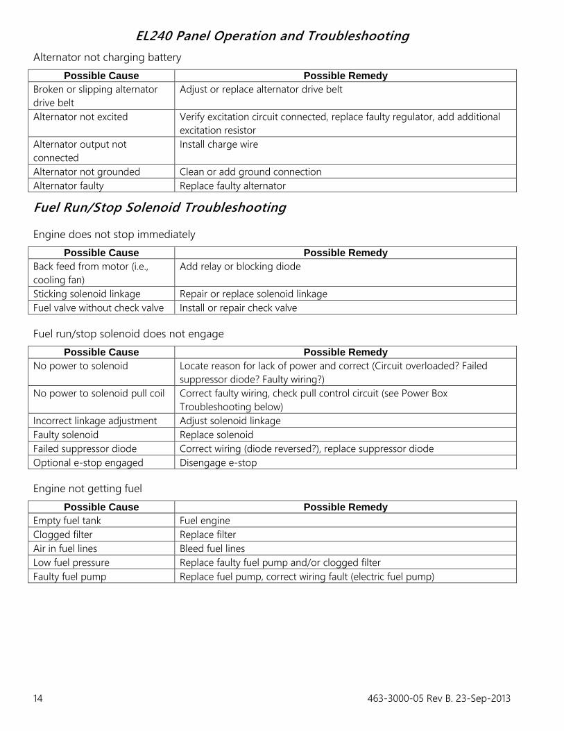
Alternator not charging battery
Possible Cause Possible Remedy
Broken or slipping alternator
drive belt
Adjust or replace alternator drive belt
Alternator not excited Verify excitation circuit connected, replace faulty regulator, add additional
excitation resistor
Alternator output not
connected
Install charge wire
Alternator not grounded Clean or add ground connection
Alternator faulty Replace faulty alternator
Fuel Run/Stop Solenoid Troubleshooting
Engine does not stop immediately
Possible Cause Possible Remedy
Back feed from motor (i.e.,
cooling fan)
Add relay or blocking diode
Sticking solenoid linkage Repair or replace solenoid linkage
Fuel valve without check valve Install or repair check valve
Fuel run/stop solenoid does not engage
Possible Cause Possible Remedy
No power to solenoid Locate reason for lack of power and correct (Circuit overloaded? Failed
suppressor diode? Faulty wiring?)
No power to solenoid pull coil Correct faulty wiring, check pull control circuit (see Power Box
Troubleshooting below)
Incorrect linkage adjustment Adjust solenoid linkage
Faulty solenoid Replace solenoid
Failed suppressor diode Correct wiring (diode reversed?), replace suppressor diode
Optional e-stop engaged Disengage e-stop
Engine not getting fuel
Possible Cause Possible Remedy
Empty fuel tank Fuel engine
Clogged filter Replace filter
Air in fuel lines Bleed fuel lines
Low fuel pressure Replace faulty fuel pump and/or clogged filter
Faulty fuel pump Replace fuel pump, correct wiring fault (electric fuel pump)
EL240 Panel Operation and Troubleshooting
463-3000-05 Rev B. 23-Sep-2013 15
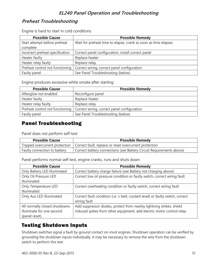
Preheat Troubleshooting
Engine is hard to start in cold conditions
Possible Cause Possible Remedy
Start attempt before preheat
complete
Wait for preheat time to elapse, crank as soon as time elapses
Incorrect preheat specification Correct panel configuration, install correct panel
Heater faulty Replace heater
Heater relay faulty Replace relay
Preheat control not functioning Correct wiring, correct panel configuration
Faulty panel See Panel Troubleshooting (below)
Engine produces excessive white smoke after starting
Possible Cause Possible Remedy
Afterglow not enabled Reconfigure panel
Heater faulty Replace heater
Heater relay faulty Replace relay
Preheat control not functioning Correct wiring, correct panel configuration
Faulty panel See Panel Troubleshooting (below)
Panel Troubleshooting
Panel does not perform self-test
Possible Cause Possible Remedy
Tripped overcurrent protection Correct fault, replace or reset overcurrent protection
Faulty connection to battery Correct battery connections (see Battery Circuit Requirements above)
Panel performs normal self-test, engine cranks, runs and shuts down
Possible Cause Possible Remedy
Only Battery LED illuminated Correct battery charge failure (see Battery not charging above)
Only Oil Pressure LED
Illuminated
Correct low oil pressure condition or faulty switch, correct wiring fault
Only Temperature LED
Illuminated
Correct overheating condition or faulty switch, correct wiring fault
Only Aux LED Illuminated Correct fault condition (i.e. v-belt, coolant level) or faulty switch, correct
wiring fault
All normally closed shutdowns
illuminate for one second
(panel reset)
Add suppressor diodes, protect from nearby lightning strikes, shield
induced spikes from other equipment, add electric motor control relay
Testing Shutdown Inputs
Shutdown switches signal a fault by ground contact on most engines. Shutdown operation can be verified by
grounding the shutdown inputs individually. It may be necessary to remove the wire from the shutdown
switch to perform this test.

16
AW
G D
ark
Gre
en
16
AW
G W
hite
14 A
WG
Pin
k/B
lack
16
AW
G Lite B
lue
16
AW
G O
range
16
AW
G T
an
12
AW
G R
ed
14
AW
G P
urp
le
16 A
WG
Yello
w/B
lack
16
AW
G Y
ello
w
16
AW
G Y
ello
w/B
lue
16
AW
G Y
ello
w/O
range
16
AW
G B
lack
12
AW
G R
ed/B
lack
A
Engin
e
P4-H
2
Acc
ess
ory
(15F)
bTach
om
ete
r
cD
+
dTem
p G
auge
ePre
ssure
Gauge
fPre
heat
Contr
ol
GBatt
ery
(30)
HSole
noid
+
jAux S
witch
2
kAux S
witch
1
lTem
p S
witch
mPre
ssure
Sw
itch
nG
round (
31)
PSta
rter
(50)
No
tes
1)
Fu
sed
ou
tpu
t 1
5A
maxim
um
. D
o n
ot
use
la
rger
fuse!
2)
Pre
hea
t C
on
tro
l con
figu
red
as o
utp
ut pro
vid
es g
round.
Option
al P
reh
ea
t C
on
tro
l con
figu
red
as inp
ut
req
uir
es b
atte
ry v
oltage to illu
min
ate
the L
ED
.
3)
Sw
itch inp
uts
will
no
t cau
se s
hu
tdow
n for
firs
t 10 s
econds.
Pre
ssure
an
d T
em
pe
ratu
re S
witch inp
uts
must b
e g
rou
nd
ed
fo
r 1
second to c
ause a
shutd
ow
n.
Aux S
witch 1
an
d A
ux S
witch 2
inp
uts
shu
tdo
wn a
s s
oo
n a
s g
round is s
ensed (
0 s
econd d
ela
y).
P
Key S
witch
Ele
ctrica
l D
iagra
m
30-5
8
30-1
5/5
4
30-1
9
30-1
7
30-5
0a
Posi
tion
4 A
8 A
18 A
70 A
70 A
35 A
70 A
30 A
40 A
5 A
17.5
A
30 A
12 V
Max
24 V
Max
0I
IIII
I
J10-H
1L1
G7
+
S
L2 -
L1
G6
+
S
L2 -
L1
G2
+
L2 -
0000
G5
+-
L1
G4
+
S
L2 -
L1
G3
+
2
L2 -
J2-H
1J18-H
1
L1
G1
+
S
L2 -
J3-H
1
J4-H
1
J5-H
1
J6-H
1
J7-H
1
J8-H
1
J11-H
1
J12-H
1
J13-H
1
J14-H
1
J15-H
1
J16-H
1
J20-H
1
J22-H
1
J21-H
1
J19-H
1
J17-H
1
J9-H
1
Part
Num
ber
Desc
ription
Date
Units
Sca
le
Tole
rance
(U
nle
ss O
therw
ise N
ote
d)
Deci
mals
INCH
METRIC
1 (
x.x
)
2 (
x.x
x)
3 (
x.x
xx)
Angle
±0.1
mm
±0.0
2 m
m
±1°
N/A
±0.1
in
±0.0
2 in
±0.0
05 in
0 (
x)
/A
±2 m
m
250 H
em
bre
e P
ark
Dr
Ste
122
?
Rosw
ell
GA 3
0076
Phone:
770.5
69.9
828
?
Fax:
770.5
69.9
829
Rev
1 o
f 1
MA
NU
FA
CT
UR
ER
OF
QU
ALIT
Y E
NG
INE
CO
MP
ON
EN
TS
IND
UST
RIE
S, IN
C.
ww
w.L
OFA.n
et
26-F
eb-2
012
EL240 P
anel w
ith G
T P
lug
N/A
N/A
© 2
007-2
012 L
OFA I
ndust
ries,
Inc.
All
rights
rese
rved.
INFO
RM
ATIO
N C
ON
TAIN
ED
IN
TH
IS D
OCU
MEN
T I
S C
ON
FID
EN
TIA
L A
ND
TH
E S
OLE P
RO
PERTY O
F L
OFA I
ND
USTRIE
S, IN
C.
Repro
duct
ion o
r dis
sem
ination, in
whole
or
in p
art
, in
any f
orm
or
mediu
m, w
ithout
expre
ss p
rior
writt
en p
erm
issi
on is
strict
ly p
rohib
ited.
LO
FA,
the L
OFA logo, Alu
flex a
nd E
L240 a
re t
radem
ark
s of
LO
FA I
ndust
ries,
Inc.
All
rights
rese
rved.
J1-H
1
J6-H
2
J3-H
2
J7-H
2
J1-H
2
P1-H
2
P2-H
2
P3-H
2
5
J2-H
2
6 7 8 9 10
KS1
Keysw
itch
15/5
4
15/5
4
50a
19
19
30
30
17
17
1 2 3 4
58
J23-H
1
16
AW
G B
lack
16
AW
G Lite B
lue
16
AW
G O
range
16
AW
G W
hite
16
AW
G R
ed
12
AW
G R
ed/B
lack
12
AW
G R
ed
J4-H
2
J5-H
2
1
BD
1
Aux S
witch
2
2Pre
heat
Contr
ol
3Sole
noid
4G
round
5Aux S
witch
1
6Tem
p S
witch
7D
+
8Pre
ssure
Sw
itch
15
Acc
ess
ory
(25)
15F
Acc
ess
ory
(Fuse
d)
50
Sta
rter
(50)
50
Sta
rter
(50)
SO
LSole
noid
+
GN
DG
round (
31)
Part
Num
ber
Desc
ription
Date
Units
Sca
le
Tole
rance
(U
nle
ss O
therw
ise N
ote
d)
Deci
mals
INCH
METRIC
1 (
x.x
)
2 (
x.x
x)
3 (
x.x
xx)
Angle
±0.1
mm
±0.0
2 m
m
±1°
N/A
±0.1
in
±0.0
2 in
±0.0
05 in
0 (
x)
/A
±2 m
m
250 H
em
bre
e P
ark
Dr
Ste
122
?
Rosw
ell
GA 3
0076
Phone:
770.5
69.9
828
?
Fax:
770.5
69.9
829
Rev
1 o
f 1
MA
NU
FA
CT
UR
ER
OF
QU
ALIT
Y E
NG
INE
CO
MP
ON
EN
TS
IND
UST
RIE
S, IN
C.
ww
w.L
OFA.n
et
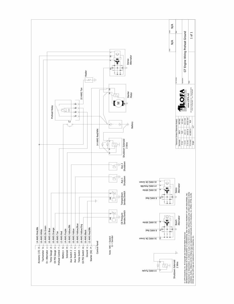
GT E
ngin
e W
irin
g P
reheat
Gro
und
N/A
N/A
Batt
ery
+ -
F1
Oil
Pre
ssure
Sender/
Sw
itch
WK
G
Tem
pera
ture
Sender/
Sw
itch
WK
G
Aux 1
Shutd
ow
nAux 2
Shutd
ow
n
Denso
Altern
ato
r
IGL
B+
P
M
Sta
rter
Moto
r
30
50
31
Bosc
h
Altern
ato
r
D+
B+
W
Delc
o
Altern
ato
r
21
B+
R
Heate
r
© L
OFA I
ndust
ries,
Inc.
All
Copyright
and T
radem
ark
Rig
hts
Rese
rved.
INFO
RM
ATIO
N C
ON
TAIN
ED
IN
TH
IS D
OCU
MEN
T I
S C
ON
FID
EN
TIA
L A
ND
TH
E S
OLE P
RO
PERTY O
F L
OFA I
ND
USTRIE
S, IN
C.
Repro
duct
ion o
r dis
sem
ination,
in w
hole
or
in p
art
, in
any f
orm
or
mediu
m, w
ithout
expre
ss p
rior
writt
en p
erm
issi
on is
strict
ly
pro
hib
ited. Alu
flex, CAN
plu
s and t
he C
AN
plu
s lo
go a
re r
egis
tere
d t
radem
ark
s of
LO
FA I
ndust
ries,
Inc.
CP600, CP750, EL240,
EP250 a
nd t
he L
OFA logo a
re t
radem
ark
s of
LO
FA I
ndust
ries,
Inc.
Note
: W
K =
Sw
itch
G =
Sen
der
Pre
heat
Rela
y
30
85
86
87
Shutd
ow
n S
ole
noid
2 W
ire
12
Shutd
ow
n S
ole
noid
3 W
ire
HC
P
A
Contr
ol Panel
Acc
eso
ry (
15)
bTach
om
ete
r
cD
+ A
ltern
ato
r
dTem
p G
auge
eO
il PSI
Gauge
fPre
heat
Contr
ol
GBatt
ery
+
HSole
noid
jAux S
witch
2
kAux S
witch
1
lTem
p S
witch
mO
il PSI
Sw
itch
nG
round
PSta
rter
(50)
14 A
WG
Pin
k/B
lk
16 A
WG
White
16 A
WG
Dk G
reen
16 A
WG
Lt
Blu
e
16 A
WG
Ora
nge
16 A
WG
Tan
12 A
WG
Red
14 A
WG
Purp
le
16 A
WG
Yello
w/B
lk
16 A
WG
Yello
w
16 A
WG
Yello
w/B
lue
16 A
WG
Yello
w/O
rg
16 A
WG
Bla
ck
12 A
WG
Red/B
lk
14 A
WG
Red/W
ht
10 A
WG
Tan
14 AWG Purple
16 AWG Dk Green
8 AWG Red
16 AWG White
16 AWG Dk Green
14 AWG Pink/Blk
16 AWG White
8 AWG Red