elimination thd using 9-level dc to ac cascade h-bridge...
TRANSCRIPT
ELIMINATION THD USING 9- LEVEL DC TO AC CASCADE H-BRIDGEMULTILEVEL INVERTER
MOHD FAIZAL BIN MUSTAPHA
A project submitted in partial fulfillment of the requirements for the award
of Master Electrical Engineering
Faculty of Electrical and Electronic Engineering
Universiti Tun Hussien Onn Malaysia
JULY 2013

v
ABSTRACT
Nowaday, electronic devices are very sensitive with harmonics. The needs for a free
harmonic and high rating power source is increased to meet the requirement from the
industries. This project is to eliminate THD using 9 level cascaded H-bridge of
multilevel DC–AC inverter. An Inverter can be broadly classified into single level
inverter and multilevel inverter. The result of 9 Cascaded H-Bridge Multilevel
Inverter level THD value are compared with 2 level inverter and 5 level Cascaded
H-Bridge Multilevel Inverter. The compared multilevel inverter to a single level
inverter has advantages like minimum harmonic distortion and higher power output.
An implementation of cascaded H-Bridge topology and a sinusoidal pulse with
modulation, synthesize a higher quality output power especially with multilevel
configuration. Experimental results are included to demonstrate effectiveness of the
proposed inverter. This project is to reduce THD contributed by the level of inverter.
vi
CONTENTS
TITLE i
DECLARATION ii
DIDICATION iii
ACKNOWLEDGEMENT iv
ABSTRACT v
CONTENTS vi
LIST OF TABLES vii
LIST OF FIGURES ix
CHAPTER 1 INTRODUCTION 1
1.0 Project Background 1
1.1 Multilevel Converter 1
1.1 Multilevel inverter 4
1.3 Merit and Demerit of Multilevel Inverter 7
1.4.The Switching 8
1.5 Control Techniques 8
1.6. Problem Statements 9
1.7 Project Objective 10
1.8.Project Scopes 11
CHAPTER 2 LITERATURE REVIEW 12
2.1 Theories 12
2.1.1 Inverter 12
2.1.2 Cascaded H-bridge Multilevel Inverter 14
2.2 Diode-Clamped Multilevel Inverter 21
2.3 Flying Capacitor Multilevel Inverter 24
2.4 Pulse Modulation Scheme 28
2.4.1 Pulse Amplitude Modulation 28

vii
2.4.2 Pulse Width Modulation 28
2.4.3 Pulse Position Modulation 28
2.4.4 Pulse Code Modulation 28
2.5. Performance parameters of inverters 29
2.6. Harmonic factor of nth harmonic. 29
2.6.1 Total harmonic distortion (THD) 29
2.6.2 Selective Harmonic elimination 30
2.6.3 Distortion factor (DF) 31
2.6.4 Lowest –order harmonics (LOH) 31
2.6.5 Sinusoidal Pulse Width Modulation 31
2.7 Fault diagnosis in multilevel converters 34
CHAPTER 3 METHODOLOGY 37
3.0. Project Methodology 37
3.1 Simulation 39
3.2 Control Scheme and Algorithm Development 40
3.3 Inverter modelling 41
3.4 System Integration and Data Collection 41
CHAPTER 4 MODELLING AND SIMULATION 42
4.0 Simulink® SimPowerSystem 42
4.1 Simulink® S-Function 44
4.2 System Overview 45
4.2.1 Control Block 45
4.2.2 Inverter Circuit Block 49
4.2.3 Measurement 50
CHAPTER 5 RESULT AND ANALYSIS 52
5.0 Voltage and current 52
5.1 Total Harmonic Distortion (THD) 55
CHAPTER 6 CONCLUSION AND SUGGESTION 56
6.0 Conclusion 56
6.1 Suggestion 57
REFERENCES 58
APPENDIX A 62
APPENDIX B 68
viii
LIST OF TABLES
2.2 Diode-clamped six-level inverter voltage levels and correspondingswitch states.
22
2.3 Flying-capacitor six-level inverter redundant voltage level andcorresponding switch states
27
5.0 Voltage and Current for 9 -Level CHB Multilevel Inverter 52
5.1 Voltage and Current for 5-Level CHB Multilevel Inverter 53
5.2 Voltage and Current for 2-Level Inverter 53
5.3 Comparism THD Value of 2-Level Inverter, 5-Level CHB MLI and9-Level CHB MLI
55

ix
LIST OF FIGURES
1.0 Multilevel Inverter Output Waveform Using 5 Equal DC sources 2
1.1 Comparison of output phase voltage waveforms:(a)two-level inverter, (b) three-level, (c) nine-level.
5
1.2 Multilevel inverter driven application overview 5
1.3 Multilevel inverter types: (a) three-level DC-MLI, (b) three-levelFC-MLI, (c) five-level CHB-MLI
6
1.4 Classification of multilevel inverter control scheme 9
2.1 Voltage source inverter(VCI) with variable DC link 13
2.2 M-Level Single Phase Cascaded H-Bridge Multilevel Inverter 15
2.3 Cascaded H-Bridge Multilevel Inverter Generalize OutputWaveform
15
2.4 Three-phase wye-connection structure for electric vehicle motordrive and battery charging.
16
2.5 Cascaded multilevel converter with transformers using standardthree-phase bi-level converters
18
2.6 Three-phase six-level structure of a diode-clamped inverter 22
2.7 Line voltage waveform for a six-level diode-clamped inverter 23
2.8 Three-phase six-level structure of a flying capacitor inverter 25
2.9 Basic Concept of Sinusoidal PWM generation 32
2.10 Switching Scheme of the PWM 33
2.11 Half-Bridge Inverter 33
2.12 Generated PWM Signal from the Mathematical Operation of Carrierand Reference Signals
34
2.13 Structure of fault diagnosis system of a multilevel cascaded H-bridges inverter.
36
3.0 Flowchart of Research Process 38
3.1 Example model circuit using Matlab Simulink 39
3.2 Flowchart of the SPWM switching scheme 40
4.0 Simulink® User Interface and Toolbox Library Browser 43
4.1 Interconnections between Simulink® and SimPowerSystem 43
x
4.2 Graphical View of Interaction between M-File S-Function withSimulink®
44
4.3 Block Diagram of Simulation Model 45
4.4 (a) 9-level CHB Multilevel Inverter Gate Driver, 46
(b) 5-level CHB Multilevel Inverter Gate Driver and (c) 2-levelInveter Gate Driver
47
4.5 Sinusoidal Reference Signal and Triangular Carrier Signals for 9-Level Multilevel Inverter
48
4.6 Switching Signals for each Individual MOSFET 48
4.7 9-Level Cascaded H-Bridge Multilevel Inverter 49
4.8 Measurement Block to Capture (a)THD , (b) Voltage and Current 50
4.9 Modelling and Simulation Setup for 9 Level Cascaded H BridgeMultilevel Inverter.
51
5.0 Output Voltage and Current of 10-level MLI at (a) m = 0.1, (b)m=0.8, (c) m=0.6, (d) m= 0.4
54

CHAPTER 1
INTRODUCTION
1.0 Project Background
Ac loads require constant or adjustable voltages at their input terminals. When such
loads are fed by inverters, it’s essential that output voltage of the inverters is so
controlled as to fulfill the requirements of AC loads. This involves coping with the
variation of DC input voltage, for voltage regulation of inverters and for the constant
volts/frequency control requirement. There are various techniques to vary the
inverter gain. The most efficient method of controlling the gain (and output voltage)
is to incorporate pulse-width modulation (PWM) control within the inverters. The
carrier based PWM schemes used for multilevel inverters is one of the most straight
forward methods of describing voltage source modulation realized by the intersection
of a modulating signal (Duty Cycle) with triangular carrier wavefroms. Multilevel
inverters are commonly used for DC to AC conversion in renewable energy
conversion [1-3].

2
1.1 Multilevel Converter
Three main multilevel converter topologies which have been mostly applied in
engineering application are known as the cascaded h-bridge converter with separated
dc sources, the diode clamp and the flying capacitor and Here, it seems important
‘multilevel inverter’. The word ‘multilevel converter’ refers to the converter itself.
The implication of the term reflects that the power can flow in one of two
directions. Power which flow from the ac side to the dc side of the multilevel
converter is operated in rectification mode. Vice-versa, the power also can flow
from the dc side to the ac side of the converter. This mode is called as inverting
mode of operation. The ‘multilevel inverter’ term basically is a ‘multilevel
converter’ that uses the inverting mode of operation.
The multilevel inverter is meant to generate a preferred ac voltage waveform
from dc voltages. Figure 1.0 shows an example of ac voltage waveform generated
from several dc voltages.
Figure 1.0: Multilevel Inverter Output
Waveform Using 5 Equal DC sources

3
In above figure, five 120 V dc source produce a pulse waveform with a peak- to-peak
voltage of 1200V. Here, the multilevel inverter produces a fair approximation to a
sinusoidal waveform. This approximation will get better and better once the
amount of dc sources increase. Ideally, once the number of dc sources reach infinity,
the pulse waveform will become a pure desired sinusoidal.
On sidering a switching scheme, there are many techniques has been developto
be implemented on a multilevel inverter. For example, Sinusoidal PWM, Space
Vector PWM, and Selective Harmonic Elimination PWM.
One of the merits of using multilevel inverter is the better total harmonic
distortion over the well-known conventional two level inverters. This can be proven
by undergo a simulation and experimental exercise.
A multilevel converter has several advantages over a conventional two-level converter
that uses high switching frequency pulse width modulation (PWM). The attractive
features of a multilevel converter can be briefly summarized as follows.
● Staircase waveform quality: Multilevel converters not only can generate the
output voltages with very low distortion, but also can reduce the dv/dt stresses;
therefore electromagnetic compatibility (EMC) problems can be reduced.
● Common-mode (CM) voltage: Multilevel converters produce smaller CM
voltage; therefore, the stress in the bearings of a motor connected to a multilevel
motor drive can be reduced. Furthermore, CM voltage can be eliminated by using
advanced modulation strategies such as that proposed in
.
● Input current: Multilevel converters can draw input current with low distortion.
● Switching frequency: Multilevel converters can operate at both fundamental
switching frequency and high switching frequency PWM. It should be noted that
lower switching frequency usually means lower switching loss and higher
efficiency.

4
Unfortunately, multilevel converters do have some disadvantages. One
particular disadvantage is the greater number of power semiconductor switches needed.
Although lower voltage rated switches can be utilized in a multilevel converter, each
switch requires a related gate drive circuit. This may cause the overall system to be
more expensive and complex.
Plentiful multilevel converter topologies have been proposed during the last two
decades. Contemporary research has engaged novel converter topologies and unique
modulation schemes. Moreover, three different major multilevel converter structures
have been reported in the literature: cascaded H-bridges converter with separate dc
sources, diode clamped (neutral-clamped), and flying capacitors (capacitor clamped).
Moreover, abundant modulation techniques and control paradigms have been
developed for multilevel converters such as sinusoidal pulse width modulation
(SPWM), selective harmonic elimination (SHE-PWM), space vector modulation
(SVM), and others. In addition, many multilevel converter applications focus on
industrial medium-voltage motor drives [11, 15, 16], utility interface for renewable
energy systems [17], flexible AC transmission system (FACTS) [18], and traction drive
systems [19].
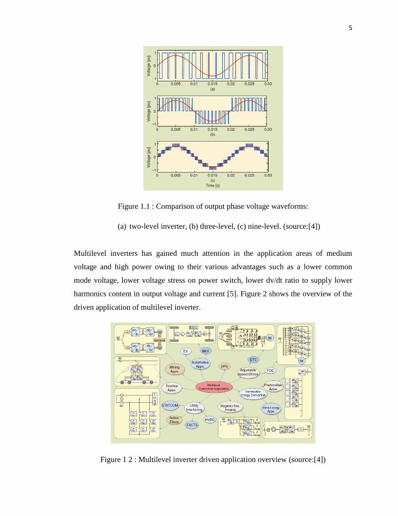
1.2 Multilevel inverter
In today market, multilevel inverter comes with many function and advantages.
These advantages are focused on improvement in the output signal quality and a nominal
power increase in the inverters. This also true if a comparism done to well known two-
level inverter[2]. The term multilevel inverter was first introduced back in 1981 by
Nabae[3]. By increasing the numbers of levels inverter, the output voltages have more
steps generating a staircase waveform, which has reduced harmonics distortion[4].
Figure 1 shows the comparison of the quality between a single-phase two-level inverter
is compared to three and nine level voltage multilevel waveform.
5
Figure 1.1 : Comparison of output phase voltage waveforms:
(a) two-level inverter, (b) three-level, (c) nine-level. (source:[4])
Multilevel inverters has gained much attention in the application areas of medium
voltage and high power owing to their various advantages such as a lower common
mode voltage, lower voltage stress on power switch, lower dv/dt ratio to supply lower
harmonics content in output voltage and current [5]. Figure 2 shows the overview of the
driven application of multilevel inverter.
Figure 1 2 : Multilevel inverter driven application overview (source:[4])
6
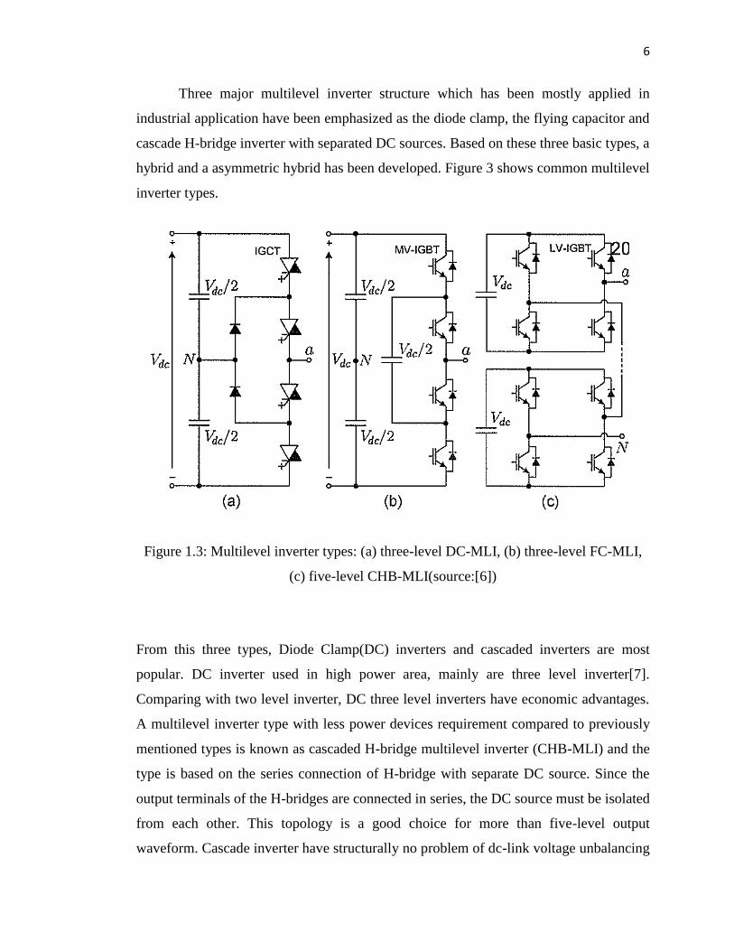
Three major multilevel inverter structure which has been mostly applied in
industrial application have been emphasized as the diode clamp, the flying capacitor and
cascade H-bridge inverter with separated DC sources. Based on these three basic types, a
hybrid and a asymmetric hybrid has been developed. Figure 3 shows common multilevel
inverter types.
Figure 1.3: Multilevel inverter types: (a) three-level DC-MLI, (b) three-level FC-MLI,
(c) five-level CHB-MLI(source:[6])
From this three types, Diode Clamp(DC) inverters and cascaded inverters are most
popular. DC inverter used in high power area, mainly are three level inverter[7].
Comparing with two level inverter, DC three level inverters have economic advantages.
A multilevel inverter type with less power devices requirement compared to previously
mentioned types is known as cascaded H-bridge multilevel inverter (CHB-MLI) and the
type is based on the series connection of H-bridge with separate DC source. Since the
output terminals of the H-bridges are connected in series, the DC source must be isolated
from each other. This topology is a good choice for more than five-level output
waveform. Cascade inverter have structurally no problem of dc-link voltage unbalancing

7
but require many separated dc sources in motor drive applications. CHB has a least
component requires for a given number of levels[5].
1.3 Merit and Demerit of Multilevel Inverter
Obviously, in recent years multilevel inverter has gained an attention from
many areas due to its advantages over the conventional inverters. The ability of
the multilevel inverter to utilize a large number of dc sources is one of the merits that
it holds. This makes multilevel inverters able to generate high voltages and thus high
power ratings. Due to this, the use of bulky and expensive transformers to produces
high voltages with conventional 12, 24 and 48-pulse inverter can be abandoned.
Another advantage of multilevel inverter is that it has a reduced Total Harmonic
Distortion (THD) with low switching frequencies. Furthermore, due to its lower
voltage steps, the value of EMI is lesser and because of its capability to utilize
multiple levels on the dc bus, the multilevel inverters able to trim down the voltage
stress on each power devices. Additionally, multilevel inverters have higher
efficiency because the devices can be switched at low frequency.
Nevertheless, there is still a pitfalls on everything created in this world including
multilevel inverter. One of the demerits of multilevel inverters is the isolated power
supplies required for each one of the multiconverter. Furthermore, number of
components is increased in multilevel inverter compared to traditional inverters. The
idea of having larger number of components also means the probability of a device
failure will increase.

8
1.4 . The Switching
There are many ways and techniques have been developed to control
multilevel inverter switching, from the very basic fundamental switching up to the
most advance space vector pulse width modulation switching scheme. But, the most
famous and applied by industries out there is the PWM switching control scheme.
PWM switching control scheme comes with advantages over the traditional
multilevel fundamental switching scheme.
One benefit of PWM methods employing much higher switching frequencies concerns
harmonics. The harmonics filtering exercise is much easier and cheaper due to the
fact that the undesirable harmonics occur at much higher switching frequencies. Also,
the produced harmonics might be above the bandwidth of some actual system. This
means that there is no power dissipation caused by the harmonics. On the contrary,
multilevel fundamental switching scheme creates harmonics at lower switching
frequencies and this increased the complexity of the filtering activity.
1.5 Control Techniques
Multilevel inverter parameter quality such as switching losses and harmonic
reduction are basically depends on the modulation strategies applied to the inverter.
Several modulation and control techniques have been developed for multilevel inverters.
As shown in Figure 1.4, control technique for the multilevel inverter cab be classified
into PWM, Selective Harmonic Elimination PWM (SHEPWM) and Optimized
Harmonics Stepped Waveform (OHSM). PWM can be classified to open loop and
closed loop. For this research, open loop modulation is proposed which will focus on
Sinusoidal PWM (SPWM).

9
Figure 1.4: Classification of multilevel inverter control scheme (source: [8])
1.6. Problem Statements
One of the important components in the system is the inverter which converts the DC
energy stored in the battery banks to AC energy which will then used by consumer
or connected to power grid. As the current trend required cleaner power source,
higher output power, less losses and almost free harmonics, people are looking
forward for better inverter. Thus, a conventional single level inverter is no more
relevant to cope with the current trend. Nowadays, industries, researches are
focusing to come out with inverter that can overcome the above mentioned issues.
As a result a multilevel inverter is created and first published by Nabae in 1980s.
Control Techinques
of Mulitlevel Inverter
SHEPWM
PWM
OHSW
Open loop
Closed loop
Simusiodal
Space Vector
VectorVector
Sigma Delta
Hysteris Current
Controller
Linear Current
Controller
DBD Current
Controller
Optimized Current
Controller

10
The best performance on higher level of inverter and a promising result on Third
Harmonic Injection PWM control technique over SPWM become a motivation for the
proposed research. Based on the simulation and several experiment done by previous
researches [6][3][7][10], as the level of inverter increases, the degree of complexity on
NPC-MLI and FC-MLI hardware is also higher. Now, modern industrial devices are
mostly based on electronic devices that are very sensitive to harmonics, even for the
induction motor whereby extra heat will be generated with higher harmonic level [16].
Therefore, the proposed work is believed shall synthesize a better quality result with
Third harmonic Injection PWM scheme but with better topology which required lesser
components and hardware complexity in hardware devolepment.
Ever since the industrial revolution in 1800, the demand for energy is
increased dramatically, especially in developing countries in-line with the economy
growth. Modern industrial machineries, electric vehicles, home appliances and public
healthcare contribute to the high demand of energy. The recent policies situation in
World Energy Outlook 2012 (WEO 12) revealed that “several fundamental trends
persist: energy demand and CO2 emission rise even higher; energy market dynamics
are increasingly determine by emerging economies; fossil fuels remain the dominant
source; and providing universal energy access to the world's poor countries continues
to be an elusive goal”.
1.7 Project Objective
There are three objective have been set for this work to be achieved at the end of the
activities.
To simulate the modelled CHB-MLI performance with the implementation of
Third harmonic Injection PWM control technique.
To analyse the multilevel inverter performance in term of THD, fundamental
and harmonic rms of the voltage and current for different levels of harmonic injection.

11
1.8.Project Scopes
The scopes of this project are:
- This research will be focus on the way to development of 9 level multilevel inverter.
- Implementation of Cascade H-Bridge MLI type and Third harmonic Injection PWM
control technique.
- Studies on improvement of total harmonic distortion among other level of harmonic
injection levels.

CHAPTER 2
LITERATURE REVIEW
2.1 Theories
2.1.1 Inverter
A device that converts DC power into AC power at desired output voltage and
frequency is call an Inverter. Phase controlled converters when operated in the inverter
mode are called line commutated inverters. But line commutated inverters require at the
output terminals an existing AC supply which is used for their commutation. This means
that line commutated inverters can’t function as isolated AC voltage sources or as
variable frequency and waveform on the AC side of the line commutated inverters can’t
be changed. On the other hand, force commutated inverters provide an independent AC
output adjustable voltage and frequency. Based on their operation the inverters can be
broadly classified into
Voltage Source Inverters(VSI)
Current Source Inverters(CSI)

13
A voltage source inverter is one where the independently controlled ac
output is a voltage waveform. A current source inverter is one where the
independently controlled ac output is a current waveform. Some industrial applications of
inverters are for adjustable- speed ac drives, induction heating, stand by air-craft power
supplies, UPS uninterruptible power supplies) for computers, HVDC transmission lines etc.
An inverter changes DC voltage from batteries or solar panels, into standard household
AC voltage so that it can be used by common tools and appliances. Essentially, it does the
opposite of what a battery charger or "converter" does. DC is usable for some small
appliances, lights, and pumps, but not much else. Some DC appliances are available, but with
the exception of lights, fans and pumps there is not a wide selection. Most other 12 volt
items we have seen are expensive and/or poorly made compared to their AC cousins. The
most common battery voltage inputs for inverters are 12, 24, and 48 volts DC - a few
models also available in other voltages. There is also a special line of inverters called a
utility intertie or grid tie, which does not usually use batteries - the solar panels or wind
generator feeds directly into the inverter and the inverter output is tied to the grid power.
The power produced is either sold back to the power company or (more commonly)
offsets a portion of the power used. These inverters usually require a fairly high input
voltage - 48 volts or more. Some, like the Sunny Boy, go up to 600 volts DC input.
Voltage source inverter (VSI) with variable DC link in Figure 2.1. DC link voltage is
varied by a DC-to DC converter or controlled rectifier.Generate “square wave” output
voltage.•Output voltage amplitude is varied as DC link is varied. Frequency of output
voltage is varied by changing the frequency of the square. wave pulses.DC
Figure 2.1 Voltage source inverter(VCI) with variable DC link.

14
2.1.2 Cascaded H-bridge Multilevel Inverter
As the name suggest, a cascaded H-bridge inverter is constructed by a series
of h- bridge inverter in cascade configuration. Basically, a three-phase inverter has a
same structure as single H-bridge inverter which use unipolar PWM. This type of
topology is relatively a new configuration after the NPC and FC structure [27]. The
topology proposed a concept with a uses of separate dc source connected for each H-
bridge to generate an ac voltage waveform. The final ac output waveform is
produced by cascading the individual H-bridge output waveform.
Figure 2.2 illustrates an m-level cascaded H-bridge inverter. Three different output
waveforms will be generated for each inverter level with an appropriate control
scheme for the switches: +Vdc, 0 and -Vdc. With S1 and S2 turned on, +Vdc will be
produced, while –Vdc can be realize with by switched on S2 and S3. The 0 output
voltage will be generated by switching on all S1, S2, S3 and S4 switches. The sum of
different individual h-bridge inverter outputs connected in series synthesized the final
ac output voltage of the multilevel inverter. An equation of m=2s+1 determine the
number of voltage levels m in a cascaded H-bridge inverters where s is the number of
independent dc source connected to the individual H-bridge inverter. For instance, an
11 level cascaded h-bridge inverter with independent dc source is illustrated in
Figure 2.3. The final output for a single phase van is a sum of va1, va2, va3, va4 and
va5.

15
Figure 2.2: M-Level Single Phase Cascaded H-Bridge Multilevel Inverter
Figure 2.3: Cascaded H-Bridge Multilevel Inverter Generalize Output Waveform

16
Multilevel cascaded inverters have been proposed for such applications as static
var generation, an interface with renewable energy sources, and for battery-based
applications. Three-phase cascaded inverters can be connected in wye, as shown in
Figure 2.4, or in delta. Peng has demonstrated a prototype multilevel cascaded static
var generator connected in parallel with the electrical system that could supply or draw
reactive current from an electrical system [20-23]. The inverter could be controlled to
either regulate the power factor of the current drawn from the source or the bus voltage
of the electrical system where the inverter was connected. Peng [20] and Joos [24] have
also shown that a cascade inverter can be directly connected in series with the electrical
system for static var compensation. Cascaded inverters are ideal for connecting
renewable energy sources with an ac grid, because of the need for separate dc sources,
which is the case in applications such as photovoltaics or fuel cells
Cascaded inverters have also been proposed for use as the main traction drive in
electric vehicles, where several batteries or ultracapacitors are well suited to serve as
SDCSs [19, 26]. The cascaded inverter could also serve as a rectifier/charger for the
batteries of an electric vehicle while the vehicle was connected to an ac supply as
shown in Figure 2.4. Additionally, the cascade inverter can act as a rectifier in a vehicle
that uses regenerative braking.
Figure 2.4 Three-phase wye-connection structure for electric vehicle motor drive and
battery charging.

17
Manjrekar has proposed a cascade topology that uses multiple dc levels, which
instead of being identical in value are multiples of each other [27-28]. He also uses a
combination of fundamental frequency switching for some of the levels and PWM
switching for part of the levels to achieve the output voltage waveform. This approach
enables a wider diversity of output voltage magnitudes; however, it also results in
unequal voltage and current ratings for each of the levels and loses the advantage of
being able to use identical, modular units for each level.
The advantages of cascaded H-bridge multilevel inverter are proven as it has
been adopt in several application across an engineering field. The modularized circuit
layout due to the same structure for each bridge allows the scalable structure of the
inverter itself. This type of topology also required less number of components for its
construction compare to NPC and FC as no extra clamping diode and voltage
balancing capacitors are required. Furthermore, in-term of safety, potential to have an
electric shock is lessen due the implementation of separate dc source. Nevertheless,
there is still a drawback coming from this kind of inverter topology as it only
restricted to certain applications wherever the independent dc source is applicable and
available.
The main advantages and disadvantages of multilevel cascaded H-bridge converters are
as follows [29, 30].
Advantages:
The number of possible output voltage levels is more than twice the number of
dc sources (m = 2s + 1).
The series of H-bridges makes for modularized layout and packaging. This will
enable the manufacturing process to be done more quickly and cheaply.

18
Disadvantages:
Separate dc sources are required for each of the H-bridges. This will limit its
application to products that already have multiple SDCSs readily available.
• • •
Another kind of cascaded multilevel converter with transformers using standard three-
phase bi-level converters has been proposed [14]. The circuit is shown in Figure 2.5.
The converter uses output transformers to add different voltages. In order for the
converter output voltages to be added up, the outputs of the three converters need to be
synchronized with a separation of 120° between each phase. For example, obtaining a
three-level voltage between outputs a and b, the output voltage can be synthesized by
Vab
= Va1-b1
+Vb1-a2
+Va2-b2
. An isolated transformer is used to provide voltage boost.
With three converters synchronized, the voltages Va1-b1
, Vb1-a2
, Va2-b2
, are all in phase;
thus, the output level can be tripled [1].
Figure 2.5. Cascaded multilevel converter with transformers using standard three-phase
bi-level converters
19
Cascaded multilevel inverter features a high modularity degree because each
inverter can be seen as a module with similar circuit topology, control structure, and
modulation [22]. Therefore in the case of a fault in one of these modules, it is
possible to replace it quickly and easily. Furthermore, with an appropriated control
strategy, it is possible to bypass the faulty module without stopping the load, bringing
an almost continuous overall availability [23].
Due to its features and benefits, many research have been conducted using
this topology as well as many analysis and synthesis have been carried out by
researches to enhance the quality and performance of cascaded multilevel inverter.
Recently in 2012, Suhitha.N and Ramani.K [15] had proposed a cascaded H-bridge
multilevel inverter boost inverter with fundamental switching scheme for electric
vehicle (EV) and hybrid EV(HEV) applications. In the research, proposed topology
offers an intuitive method for minimizing the total harmonic distortion (THD) of the
output voltage of the inverter.
Alireza Nami, Firuz Zare, Arindam Ghosh and Frede Blaabjerg had cascaded
the diode-clamped multilevel H-bridge cell with the three-level conventional inverter
in their work [24]. Idea of cascading multilevel H-bridge cells is used in [24] to
propose different configurations using a seven-level symmetrical and asymmetrical
diode-clamped H-bridge converter supplied with a multi-output boost (MOB)
converter, cascaded with classical three-level inverters. The MOB converter can
solve the capacitor voltage imbalance problem as well as boost the low output voltage
of renewable energy system such as solar cells to desired value of the diode-
clamp dc link voltage. From this, a nineteen output voltage levels performance was
achieved, which has more voltage levels as well as lower voltage, and current THD
rather than using a symmetrical diode-clamped inverter with the same configuration
and equivalent number of power component.

20
Due to the fact that nowadays most of the modern industrial devices are
based on electronic devices, they are very sensitive to disturbance and less tolerant to
power quality problems. In 2011, N.Chellammal, K.N.V Prasad, S.S Dash, Y.S Anil
Kumar and A.Murali Krishna had done a performance analysis of three phase cascaded
H-bridge multilevel inverter for under voltage and over voltage conditions [25]. The
work involved a design of closed loop control system using PI controller in order to
maintain load voltage constant for under voltage and over voltage conditions. The
triggering pulses to cascaded H-bridge multilevel inverter is given using multi
carrier phase shift technique.
In the researches of multilevel inverters, its corresponding PWM control
strategies are one of the research hot points. Therefore several works were carried
out to compare and analyze on different type or technique to control the switching of
the multilevel inverters. V.Kumar Chinnaiyan, Jovitha Jerome, J.Karpagam and
T.Suresh had proposed a comparison between different switching strategies for
cascaded multilevel inverters, based on sinusoidal pulse width modulation (SPWM)
and space vector modulation (SVM) [8].
The work is based on simulation of 5-level cascaded multilevel inverter using
Matlab and Simulink® software. The research reveal that the gain of the inverter is
increased when using THIPWM, but a third order harmonic is present in the phase
voltage, which causes serious problems when the neutral point is grounded. What
have been done by a group of researchers from Greater India also carried out by
Berrezzek Farid and Omeiri Amar. In [26], they are using new types of modulation in
order to increase the output voltages of the inverter for the same continuous voltage
supply. The so-called new modulation technique involves SPWM, THIPWM and
SVPWM. The comparison studies show reveals that SVPWM and THIPWM
technique give a better performance compared to conventional SPWM method. Based
on above review a conclusion on the advantages of multilevel inverter are clear.
Several researches reveal that the use of CHB-MLI has advantages over other
multilevel inverter topologies and obviously better when the higher degree of levels

21
in introduced. With the implementation of cascaded H-bridge topology and
SPWM method, it is believe that a better and efficient inverter shall be product.
2.2 Diode-Clamped Multilevel Inverter
The neutral point converter proposed by Nabae, Takahashi, and Akagi in 1981 was
essentially a three-level diode-clamped inverter [5]. In the 1990s several researchers
published articles that have reported experimental results for four-, five-, and six-level
diode-clamped converters for such uses as static var compensation, variable speed
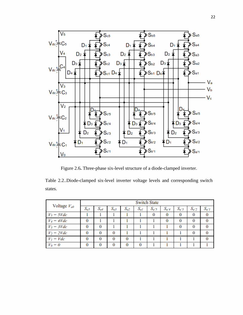
motor drives, and high-voltage system interconnections [18-31]. A three-phase six-
level diode-clamped inverter is shown in Figure 2.6. Each of the three phases of the
inverter shares a common dc bus, which has been subdivided by five capacitors into six
levels. The voltage across each capacitor is Vdc
, and the voltage stress across each
switching device is limited to Vdc
through the clamping diodes. Table 2.2.1 lists the
output voltage levels possible for one phase of the inverter with the negative dc rail
voltage V0
as a reference. State condition 1 means the switch is on, and 0 means the
switch is off. Each phase has five complementary switch pairs such that turning on one
of the switches of the pair requires that the other complementary switch be turned off.
The complementary switch pairs for phase leg a are (Sa1
, Sa’1
), (Sa2
, Sa’2
), (Sa3
, Sa’3
),
(Sa4
, Sa’4
), and (Sa5
, Sa’5
). Table 2.1.3 also shows that in a diode-clamped inverter, the
switches that are on for a particular phase leg are always adjacent and in series. For a
six-level inverter, a set of five switches is on at any given time.
22
Figure 2.6. Three-phase six-level structure of a diode-clamped inverter.
Table 2.2..Diode-clamped six-level inverter voltage levels and corresponding switch
states.

23
The line voltage Vab
consists of a phase-leg a voltage and a phase-leg b voltage.
The resulting line voltage is an 11-level staircase waveform. This means that an m-
level diode-clamped inverter has an m-level output phase voltage and a (2m-1)-level
output line voltage.
Although each active switching device is required to block only a voltage level
of Vdc
, the clamping diodes require different ratings for reverse voltage blocking.
Using phase a of Figure 2.7 as an example, when all the lower switches Sa’1
through
Sa’5
are turned on, D4
must block four voltage levels, or 4Vdc
. Similarly, D3
must block
3Vdc
, D2
must block 2Vdc
, and D1
must block Vdc
. If the inverter is designed such that
each blocking diode has the same voltage rating as the active switches, Dn
will require
n diodes in series; consequently, the number of diodes required for each phase would
be (m-1) × (m-2). Thus, the number of blocking diodes is quadratically related to the
number of levels in a diode-clamped converter [30].
One application of the multilevel diode-clamped inverter is an interface
between a high-voltage dc transmission line and an ac transmission line [30]. Another
application would be as a variable speed drive for high-power medium-voltage (2.4 kV
to 13.8 kV) motors as proposed in [3, 6, 25, 29-31]. Static var compensation is an
additional function for which several authors have proposed for the diode-clamped
converter. The main advantages and disadvantages of multilevel diode-clamped
converters are as follows [1- 3]:
Figure 2.7. Line voltage waveform for a six-level diode-clamped inverter
24
Advantages:
All of the phases share a common dc bus, which minimizes the capacitance
requirements of the converter. For this reason, a back-to-back topology is not only
possible but also practical for uses such as a high-voltage back-to-back inter-
connection or an adjustable speed drive.
The capacitors can be pre-charged as a group.
Efficiency is high for fundamental frequency switching.
Disadvantages:
Real power flow is difficult for a single inverter because the intermediate dc levels
will tend to overcharge or discharge without precise monitoring and control.
The number of clamping diodes required is quadratically related to the number of
levels, which can be cumbersome for units with a high number of levels.
2.3. Flying Capacitor Multilevel Inverter
Meynard and Foch introduced a flying-capacitor-based inverter in 1992 [32]. The
structure of this inverter is similar to that of the diode-clamped inverter except that
instead of using clamping diodes, the inverter uses capacitors in their place. The circuit
topology of the flying capacitor multilevel inverter is shown in Figure 31.7. This
topology has a ladder structure of dc side capacitors, where the voltage on each
capacitor differs from that of the next capacitor. The voltage increment between two
adjacent capacitor legs gives the size of the voltage steps in the output waveform.

58
REFERENCES
[1] K.V. Kumar, P.A Micheal, J.P. John, S.S. Kumar, “ Simulation and comparison
of spwm and svpm control for three phase inverter,” in APRN journal of Eng. And
APP. Sci. Vol.5, no.7, pp. 61-74, jul.2010
[2] Jose Rodriguez, J. S. Lai, F. Z. Peng, “Multilevel Inverter: A survey of topologies,
control and applications,” in IEEE Trans. Ind. Elect., vol. 49, no. 4 , pp. 724-738,
aug.2002.
[3] A.Nabae, I. Takhashi, and H. Akagi, “A new neutral –point clamped pwm
inverter,” in IEEE Trans. Ind. Elect., vol. IA-A7, no. 5 , pp. 518-523, sep/oct.1981.
[4] Leopoldo G, Jose Rodriguez, Jose I. Leon , Samir Kouro, “The age of multilevel
converters arrives,” in IEE Industrial Electronic Magazine, June 2008.
[5] Illami Colak, Ersan Kabalci, Ramazan Bayindir, “Review of multilevel voltage
inverter topologies and control schemes,” in energy Conversion And Management
52(2011) 1114-1128, Sept.2010
[6] S.Kouro, M.Malinowski, K.Gapokumar, J.Pou, L.G. Franquelo, B.Wu,J.Rodriguez,
M.A.Perez , J.I.Leon, “Recent Advance & Industrial Applications of multilevel
Converter”, in IEEE Trans. On Industrial Electronics, Vol.57, n0.8, aug 2010,
pp.2553-2580.
[7] S.X. Tao, W.F. jiang, S. Li, “A new multilevel space vector pwm technique for h-
bridge cascaded inverter”, in 2007 second IEEE COnf. On Ind. Elec. And Appl.,
pp. 2427-2430
59
[8] V.Kumar Chinnaiyan, J.Jerome, J.Karpagam, T.Suresh, “Control Techniques for
Multilevel Voltage source Inverter”, in the 8 International Power Engineering
Conference(PEC 2007)
[9] Surin Khomfoi, Leon M. Tolbert, “Chapter 31 Multilevel Power Converter”, book
chapter, The university of Tennesse.
[10] A. K Gupta A. M Khambadkone, “A general space vector pwm algorithm for
multilevel inverter, including operation in overmodulation range’, in IEEE
Trans.Pow. elect., vol.22,no.2, pp. 517-526, mar.2007.
[11] Anish, T.M.R. Baiju, “SVPWM Controller for multilevel inverter”, in 10
Conference on Technological trends (NCTT09) pp.218-223, nov.2009.
[12] P. S. Kumar, J. Amarnath, S. V. L. Narasimham, “An effective space vector pwm
method for multilevel inverter based on two level inverter”, in Int. Journal of
Comp And Elec. Eng., vol.2, no.2, pp. 243-250, apr.2010.
[13] llami Colak, Ramazan Bayindir, Ersan Kabalci, “A modified Harmonic
Mitigation Analysis Using Third Harmonic Injection PWm in Multilevel Inverter
Control”, in 14 International Power electronic and Motion Control Conference,
EPE-PEMC2010, T2.215-T2.220
[14] M.A.A Younis, N.ARahim, S. Mekhilef, “harmonic Reduction in Three Phase
parallel Connected Inverter”, in world Academy of Sience, Engineering and
Technology 50, 2009, pp.944-949.
[15] Alireza Nami, Firuz Zare, Arindam Ghosh, Freed Blaabjerg, “A Hybrid Cascade
Converter Topolgy With Series-connected Symmetrical and Asymmtrical Diode
Clamped H-Bridge Cells”, in IEE Trans. On Power Electronics, vol.26, no.1, Jan
2011, pp.51-65.
[16] N. Chellamall, K.N.V Prasad, S.S. Dash, Y.S Anil Kumar, A. Murali Krishna,
“Performance Analysis of three phase Cascaded H-Bridge multilevel Inverter for

60
under voltage and over voltage condition”,in Chennai And Dr.MGR University
Sec. Int. Conf. on SEICON 2011, July 2011.
17] C. Aghion, O.Ursaru, M.Lucanu, C.Pavaluta, O.Botez, “Motor Control Strategy
based on ISCPWM and THIPWM”, in 10 International Symposium on Signal,
Circuit and System(ISSCS), 2011,pp.1-4.
[18] M.A.A Younis, N.A. Rahim, S.Mekhlief, “High Efficiency THIPWM Three
Phase Inverter for Grid Connected System”, in IEEE Symposium on Industrial
Electronic and Applications(ISIEA 2010), oct.2010
[19] L. M. Tolbert, F. Z. Peng, T. G. Habetler, “Multilevel Inverters for Electric
Vehicle Applications,” IEEE Workshop on Power Electronics in
Transportation, Oct 22-23, 1998, Dearborn, Michigan, pp. 1424-1431.
[20] F. Z. Peng, J. S. Lai, J. W. McKeever, J. VanCoevering, “A Multilevel
Voltage-Source Inverter with Separate DC Sources for Static Var Generation,”
IEEE Transactions on Industry Applications, vol. 32, no.5, Sept. 1996, pp.
1130-1138.
[21] F. Z. Peng, J. S. Lai, “Dynamic Performance and Control of a Static Var
Generator Using Cascade Multilevel Inverters,” IEEE Transactions on Industry
Applications, vol. 33, no. 3, May 1997, pp. 748-755. [22] F. Z. Peng, J. W.
McKeever, D. J. Adams, “A Power Line Conditioner Using Cascade Multilevel
Invertersfor Distribution Systems,” Conference Record - IEEE Industry
Applications Society 32nd Annual Meeting,1997, pp. 1316-1321.
[23] F. Z. Peng, J. W. McKeever, D. J. Adams, “Cascade Multilevel Inverters for
Utility Applications,” Proceedings of 23rd International Conference on
Industrial Electronics, Control, and Instrumentation,1997, pp. 437-442.
[24] G. Joos, X. Huang, B. T. Ooi, “Direct-Coupled Multilevel Cascaded Series
VAR Compensators,”Conference Record – IEEE Industry Applications Society
32nd Annual Meeting, 1997, pp. 1608-1615.
[25] R. W. Menzies, Y. Zhuang, “Advanced Static Compensation Using a Multilevel
GTO Thyristor Inverter,”IEEE Transactions on Power Delivery, vol. 10, no. 2,
April 1995, pp. 732-738.

61
[26] Leon M. Tolbert, Fang Z. Peng, Tim Cunnyngham, John N. Chiasson, "Charge
Balance Control Schemes for Multilevel Converter in Hybrid Electric Vehicles,"
IEEE Transactions on Industrial Electronics, vol.49, no. 5, October 2002, pp.
1058-1065
[27] M. D. Manjrekar, T. A. Lipo, “A Hybrid Multilevel Inverter Topology for
Drive Applications,” IEEE Applied Power Electronics Conference, 1998, pp.
523-529.
[28] M. D. Manjrekar, T. A. Lipo, “A Generalized Structure of Multilevel Power
Converter,” IEEE Conference on Power Electronics, Drives, and Energy Systems,
Australia, 1998, pp. 62-67.
[29] C. Hochgraf, R. Lasseter, D. Divan, T. A. Lipo, “Comparison of Multilevel
Inverters for Static Var Compensation,” Conference Record - IEEE Industry
Applications Society 29th Annual Meeting, 1994, pp.921-928.
[30] J. S. Lai, F. Z. Peng, “Multilevel Converters - A New Breed of Power
Converters,” IEEE Transactions on Industry Applications, vol. 32, no. 3, May
1996, pp. 509-517