elite coriolis flow and density meters2 micro motion® elite® flow and density meters micro motion...
TRANSCRIPT

Product Data SheetPS-00374, Rev. IAugust 2007
Micro Motion® ELITE® Coriolis meters are the leading precision flow and density measurement solutions. ELITE meters offer the most accurate and repeatable measurement available for liquids, gases, or slurries.
Best precision flow and density measurement
• Unique design delivers unparalleled measurement sensitivity and stability
• Guarantees consistent, reliable performance over the widest flow range
• In-situ meter verification delivers fast, actionable, simplified performance checks
Superior performance in the most challenging applications
• Industry standard for custody transfer and critical process control
• Best two-phase flow capability for batching, loading, and entrained air applications
• Immune to fluid, process, or environmental effects for superb measurement confidence
High performance compact drainable Coriolis meter
Peak performance Coriolis meter
Hygienic compact drainable Coriolis meter
Straight tube full-bore Coriolis meter
General purpose flow-only Coriolis meter
F-Series
ELITE®
H-Series
T-Series
R-Series
Extreme low-flow Coriolis meter
LF-Series
Micro Motion® ELITE® Coriolis Flow and Density Meters
2 Micro Motion® ELITE® Flow and Density Meters
Micro Motion ELITE flow and density meters
Micro Motion Coriolis meters meet a vast range of application needs, ranging from extreme low-flow up to high-flow, high-capacity lines. Cryogenic, hygienic, high-temperature, and high-pressure— Micro Motion meters can handle them all. Micro Motion meters are available with a variety of wetted parts to ensure the best material compatibility.
Coriolis meters. Coriolis meters offer dramatic benefits over traditional volumetric measurement technologies. Coriolis meters:
• Deliver accurate and repeatable process data over a wide range of flow rates and process conditions.
• Provide direct inline measurement of mass flow and density, and also measure volume flow and temperature—all from a single device.
• Have no moving parts, so maintenance costs are minimal.
• Have no requirements for flow conditioning or straight pipe runs, so installation is simplified and less expensive.
• Provide advanced diagnostic tools for both the meter and the process.
ELITE Coriolis meters. Micro Motion ELITE meters are the leading meters for precision flow and density measurement. ELITE meters offer the most accurate measurement available for virtually any process fluid, while exhibiting exceptionally low pressure drop. Every ELITE meter features standard secondary containment, and is available with stainless steel or nickel-alloy wetted parts and a wide variety of process connections to meet your every need.
Now with in-situ meter verification, ELITE delivers the best in measurement and ease of use for critical applications. ELITE meters offer the best measurement performance for mass, density, and volume, regardless of process or environmental conditions. ELITE meters provide measurement capability for two-phase flow, liquid, and gas custody transfer, and process conditions from –400 °F (–240 °C) to 662 °F (350 °C).
Contents
Liquid flow performance . . . . . . . . . . . . . . . . . . . . 4
Gas flow performance . . . . . . . . . . . . . . . . . . . . . . 6
Density performance (liquid only) . . . . . . . . . . . . . 8
Power consumption . . . . . . . . . . . . . . . . . . . . . . . . 8
Vibration limits . . . . . . . . . . . . . . . . . . . . . . . . . . . . 8
Temperature specifications . . . . . . . . . . . . . . . . . . 9
Pressure ratings . . . . . . . . . . . . . . . . . . . . . . . . . 11
Environmental effects . . . . . . . . . . . . . . . . . . . . . 12
Hazardous area classifications . . . . . . . . . . . . . . 13
Materials of construction . . . . . . . . . . . . . . . . . . . 18
Weight . . . . . . . . . . . . . . . . . . . . . . . . . . . . . . . . . 18
Dimensions . . . . . . . . . . . . . . . . . . . . . . . . . . . . . 19
Fitting options . . . . . . . . . . . . . . . . . . . . . . . . . . . 42
Ordering information . . . . . . . . . . . . . . . . . . . . . . 51
Micro Motion® ELITE® Flow and Density Meters 3
Micro Motion ELITE flow and density meters
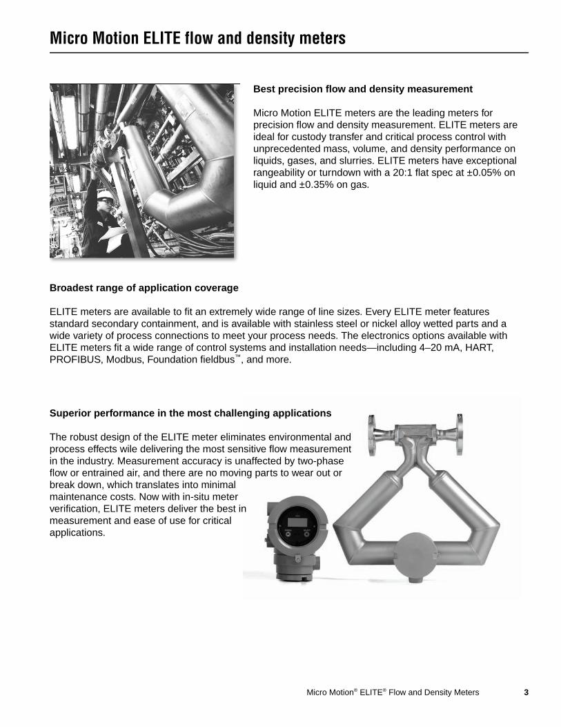
Best precision flow and density measurement
Micro Motion ELITE meters are the leading meters for precision flow and density measurement. ELITE meters are ideal for custody transfer and critical process control with unprecedented mass, volume, and density performance on liquids, gases, and slurries. ELITE meters have exceptional rangeability or turndown with a 20:1 flat spec at ±0.05% on liquid and ±0.35% on gas.
Superior performance in the most challenging applications
The robust design of the ELITE meter eliminates environmental and process effects wile delivering the most sensitive flow measurement in the industry. Measurement accuracy is unaffected by two-phase flow or entrained air, and there are no moving parts to wear out or break down, which translates into minimal maintenance costs. Now with in-situ meter verification, ELITE meters deliver the best in measurement and ease of use for critical applications.
Broadest range of application coverage
ELITE meters are available to fit an extremely wide range of line sizes. Every ELITE meter features standard secondary containment, and is available with stainless steel or nickel alloy wetted parts and a wide variety of process connections to meet your process needs. The electronics options available with ELITE meters fit a wide range of control systems and installation needs—including 4–20 mA, HART, PROFIBUS, Modbus, Foundation fieldbus™, and more.

4 Micro Motion® ELITE® Flow and Density Meters
Liquid flow performance
Mass Volume(1)
(1) Specifications for volumetric flow rate are based on a process-fluid density of 1 g/cm3 (1000 kg/m3). For fluids with density other than 1 g/cm3 (1000 kg/m3), the volumetric flow rate equals the mass flow rate divided by the fluid’s density.
lb/min kg/h gal/min l/h bbl/hr m3/h
Maximum flow rate CMF010 4 108 0.4 108CMF025 80 2180 10 2180CMF050 250 6800 30 6800CMF100 1000 27,200 120 27,200CMF200 3200 87,100 385 87,100 550 87CMF300 10,000 272,000 1200 272,000 1700 272CMF400 20,000 545,000 2400 545,000 3400 545
Mass and volume flow accuracy(2)(3)
(2) Stated flow accuracy includes the combined effects of repeatability, linearity, and hysteresis. All specifications for liquids are based on reference conditions of water at 68 to 77 °F (20 to 25 °C) and 15 to 30 psig (1 to 2 bar), unless otherwise noted.
(3) The calibration option for ±0.05% flow accuracy is not available with high-temperature sensor models.
Model 2400S transmitter or enhanced core processor
±0.05% of rate(4)(5)
(4) When flow rate is less than zero stability / 0.0005, accuracy = ±[(zero stability / flow rate) × 100]% of rate, and repeatability = ±[½(zero stability / flow rate) × 100]%.
(5) When ordered with the ±0.10% factory calibration option, accuracy on liquid = ±0.10% when flow rate ≥ zero stability / 0.001. When flow rate < zero stability / 0.001, accuracy = ±[(zero stability / flow rate) × 100]% of rate andrepeatability = ±[½(zero stability / flow rate) × 100]% of rate.
Transmitter with MVD technology
±0.10% of rate(6)
(6) When flow rate is less than zero stability / 0.001, accuracy = ±[(zero stability / flow rate) × 100]% of rate andrepeatability = ±[½(zero stability / flow rate) × 100]% of rate.
All other transmitters ±0.10% ±[(zero stability / flow rate) × 100]% of rate
Mass and volume flow repeatability
Model 2400S transmitter or enhanced core processor
±0.025% of rate(4) (5)
Transmitter with MVD technology
±0.05% of rate(6)
All other transmitters ±0.05% ±[½(zero stability / flow rate) × 100]% of rate
lb/min kg/hZero stability CMF010 0.000075 0.002
CMF010P 0.00015 0.004CMF025 0.001 0.027CMF050 0.006 0.163CMF100 0.025 0.680CMF200 0.08 2.18CMF300 0.25 6.80CMF400 1.50 40.91
Micro Motion® ELITE® Flow and Density Meters 5
Liquid flow performance continued
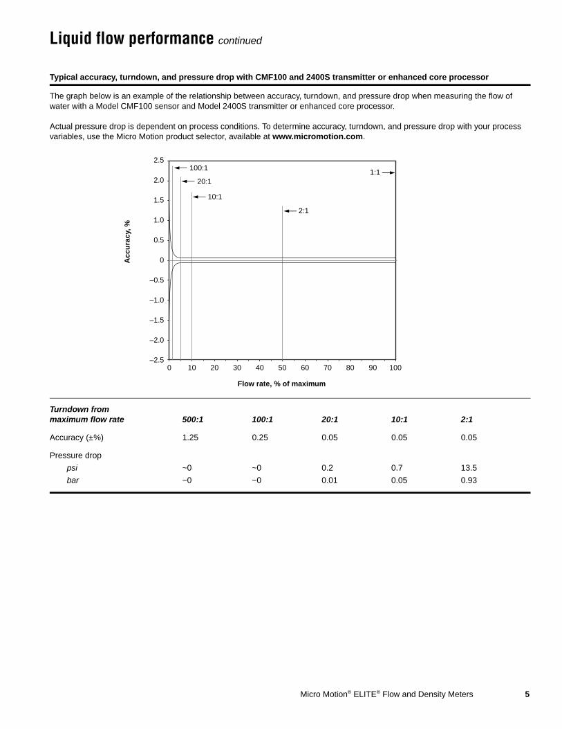
Typical accuracy, turndown, and pressure drop with CMF100 and 2400S transmitter or enhanced core processor
The graph below is an example of the relationship between accuracy, turndown, and pressure drop when measuring the flow of water with a Model CMF100 sensor and Model 2400S transmitter or enhanced core processor.
Actual pressure drop is dependent on process conditions. To determine accuracy, turndown, and pressure drop with your process variables, use the Micro Motion product selector, available at www.micromotion.com.
Turndown from maximum flow rate 500:1 100:1 20:1 10:1 2:1
Accuracy (±%) 1.25 0.25 0.05 0.05 0.05
Pressure drop
psi ~0 ~0 0.2 0.7 13.5
bar ~0 ~0 0.01 0.05 0.93
Flow rate, % of maximum
Acc
ura
cy, %
–2.5
–2.0
–1.5
–1.0
–0.5
0
0.5
1.0
1.5
2.0
2.5
0 100908070605040302010
100:1
20:11:1
2:1
10:1
6 Micro Motion® ELITE® Flow and Density Meters
Gas flow performance
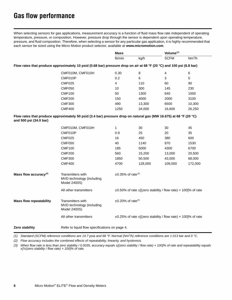
When selecting sensors for gas applications, measurement accuracy is a function of fluid mass flow rate independent of operating temperature, pressure, or composition. However, pressure drop through the sensor is dependent upon operating temperature, pressure, and fluid composition. Therefore, when selecting a sensor for any particular gas application, it is highly recommended that each sensor be sized using the Micro Motion product selector, available at www.micromotion.com.
Mass Volume(1)
(1) Standard (SCFM) reference conditions are 14.7 psia and 68 °F. Normal (Nm3/h) reference conditions are 1.013 bar and 0 °C.
lb/min kg/h SCFM Nm3/h
Flow rates that produce approximately 10 psid (0.68 bar) pressure drop on air at 68 °F (20 °C) and 100 psi (6.8 bar)
CMF010M, CMF010H 0.30 8 4 6
CMF010P 0.2 6 3 5
CMF025 4 110 60 90
CMF050 10 300 145 230
CMF100 50 1300 640 1000
CMF200 150 4000 2000 3100
CMF300 490 13,300 6500 10,300
CMF400 1250 34,000 16,600 26,250
Flow rates that produce approximately 50 psid (3.4 bar) pressure drop on natural gas (MW 16.675) at 68 °F (20 °C) and 500 psi (34.0 bar)
CMF010M, CMF010H 1 30 30 45
CMF010P 0.9 25 20 35
CMF025 16 450 380 600
CMF050 40 1140 970 1530
CMF100 185 5000 4300 6700
CMF200 560 15,200 13,000 20,500
CMF300 1850 50,500 43,000 68,000
CMF400 4700 128,000 109,000 172,000
Mass flow accuracy(2)
(2) Flow accuracy includes the combined effects of repeatability, linearity, and hysteresis.
Transmitters with MVD technology (including Model 2400S)
±0.35% of rate(3)
(3) When flow rate is less than zero stability / 0.0035, accuracy equals ±[(zero stability / flow rate) × 100]% of rate and repeatability equals ±[½(zero stability / flow rate) × 100]% of rate.
All other transmitters ±0.50% of rate ±[(zero stability / flow rate) × 100]% of rate
Mass flow repeatability Transmitters with MVD technology (including Model 2400S)
±0.20% of rate(3)
All other transmitters ±0.25% of rate ±[(zero stability / flow rate) × 100]% of rate
Zero stability Refer to liquid flow specifications on page 4.

Micro Motion® ELITE® Flow and Density Meters 7
Gas flow performance continued
Typical mass flow accuracy and pressure drop with CMF100 and transmitter with MVD technology
Air at 68 °F (20 °C), static pressures as indicated on graph
Natural gas (MW 16.675) at 68 °F (20 °C), static pressure as indicated on graph
Standard or Normal Volumetric CapabilityStandard and normal volumes are “quasi mass” flow units for any fixed composition fluid. Standard and normal volumes do not vary with operating pressure, temperature, or density. With knowledge of density at standard or normal conditions (available from reference sources), a Micro Motion meter can be configured to output in standard or normal volume units without the need for pressure, temperature, or density compensation. Contact your local sales representative for more information.
1.5
1.0
0.5
0
5
10
Flow rate
Pre
ssu
re d
rop
Acc
ura
cy (
± %
of
rate
)
0 20 40 60 80 100 120 140 1600
0 1000 2000 3000 4000
lb/min
kg/h
300
200
100
0
0.5
0.4
0.3
0.2
0.1
0
0.9
0.8
0.7
0.6
barInchesH2Opsi
100 psig(7 bar)
500 psig(35 bar)
1000 psig(70 bar)
1.5
1.0
0.5
0
5
10
Flow rate
Pre
ssu
re d
rop
Acc
ura
cy (
± %
of
rate
)
0 20 40 60 80 100 120 140 1600
0 1000 2000 3000 4000
lb/min
kg/h
300
200
100
0
0.5
0.4
0.3
0.2
0.1
0
0.9
0.8
0.7
0.6
barInchesH2Opsi
100 psig(7 bar)
500 psig(35 bar)
1000 psig(70 bar)

8 Micro Motion® ELITE® Flow and Density Meters
Density performance (liquid only)
Power consumption
Vibration limits
With 2400S transmitter or enhanced core processor
With transmitter with MVD technology (except Model 2400S), standard core processor, or RFT9739 transmitter
With IFT9701 transmitter
g/cm3 kg/m3 g/cm3 kg/m3 g/cm3 kg/m3
Accuracy(1)
(1) Accuracy includes the combined effects of repeatability, linearity, and hysteresis. Specifications for ±0.0002 g/cm3 (±0.2 kg/m3) density accuracy are based on reference conditions of water at 68 to 140 °F (20 to 60 °C) and 15 to 30 psig (1 to 2 bar). All other accuracy specifications are based on reference conditions of water at 68 to 77 °F (20 to 25 °C) and 15 to 30 psig (1 to 2 bar), unless otherwise noted.
Model CMF010 and high-temperature models
±0.0005 ±0.5 ±0.0005(2)
(2) For these combinations of sensors and transmitters, density accuracy and repeatability differ slightly from standard meter performance. Contact Micro Motion for performance data.
±0.5(2) ±0.002(2) ±2.0(2)
All other models ±0.0002 ±0.2 ±0.0005 ±0.5 ±0.002 ±2.0
Repeatability Model CMF010 and high-temperature models
±0.0002 ±0.2 ±0.0002(2) ±0.2(2) ±0.001(2) ±1.0(2)
All other models ±0.0001 ±0.1 ±0.0002 ±0.2 ±0.001 ±1.0
Range All models up to 5 up to 5000 up to 5 up to 5000 up to 5 up to 5000
Meter with core processor 4 watts maximum
Meter with Model 2400S transmitter 7 watts maximum
Meter with Model 1700/2700 transmitter Refer to transmitter documentation
Meets IEC 68.2.6, endurance sweep, 5 to 2000 Hz, 50 sweep cycles at 1.0 g

Micro Motion® ELITE® Flow and Density Meters 9
Temperature specifications
Accuracy All models ±1 °C ± 0.5% of reading in °C
Repeatability All models ±0.2 °C
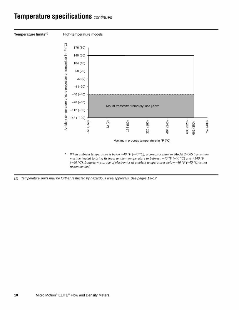
Temperature limits(1)
(1) Temperature limits may be further restricted by hazardous area approvals. See pages 13–17.
All models except high-temperature models(2)
(2) The extended mount option allows the sensor case to be insulated without covering the transmitter, core processor, or junction box, but does not affect temperature ratings.
Am
bien
t tem
pera
ture
of c
ore
proc
esso
r or
tran
smitt
er in
°F
(°C
)
Maximum process temperature in °F (°C)
Mount transmitter remotely; use j-box
–148 (–100)
–112 (–80)
–76 (–60)
–40 (–40)
–4 (–20)
32 (0)
68 (20)
104 (40)
140 (60)
176 (80)
–400
(–2
40)
–292
(–1
80)
–184
(–1
20)
–76
(–60
)
32 (
0)
140
(60)
356
(180
)
464
(240
)
248
(120
)
400
(204
)
113 (45)
Mount transmitter remotely; use j-box
* When ambient temperature is below –40 °F (–40 °C), a core processor or Model 2400S transmitter must be heated to bring its local ambient temperature to between –40 °F (–40 °C) and +140 °F (+60 °C). Long-term storage of electronics at ambient temperatures below –40 °F (–40 °C) is not recommended.
* For the purposes of selecting electronics options, this graph should be used only as a general guide. If your process conditions are close to the gray areas, it may be inappropriate to use electronics options other than a junction box. Consult with your Micro Motion representative.
140(60)
10 Micro Motion® ELITE® Flow and Density Meters
Temperature specifications continued
Temperature limits(1)
(1) Temperature limits may be further restricted by hazardous area approvals. See pages 13–17.
High-temperature models
–148 (–100)
–112 (–80)
–76 (–60)
–40 (–40)
–4 (–20)
32 (0)
68 (20)
104 (40)
140 (60)
176 (80)
Mount transmitter remotely; use j-box*
* When ambient temperature is below –40 °F (–40 °C), a core processor or Model 2400S transmitter must be heated to bring its local ambient temperature to between –40 °F (–40 °C) and +140 °F (+60 °C). Long-term storage of electronics at ambient temperatures below –40 °F (–40 °C) is not recommended.
662
(350
)
–58
(–50
)
32 (
0)
464
(240
)
320
(160
)
176
(80)
752
(400
)
608
(320
)
Maximum process temperature in °F (°C)
Am
bien
t tem
pera
ture
of c
ore
proc
esso
r or
tran
smitt
er in
°F
(°C
)
Micro Motion® ELITE® Flow and Density Meters 11
Pressure ratings
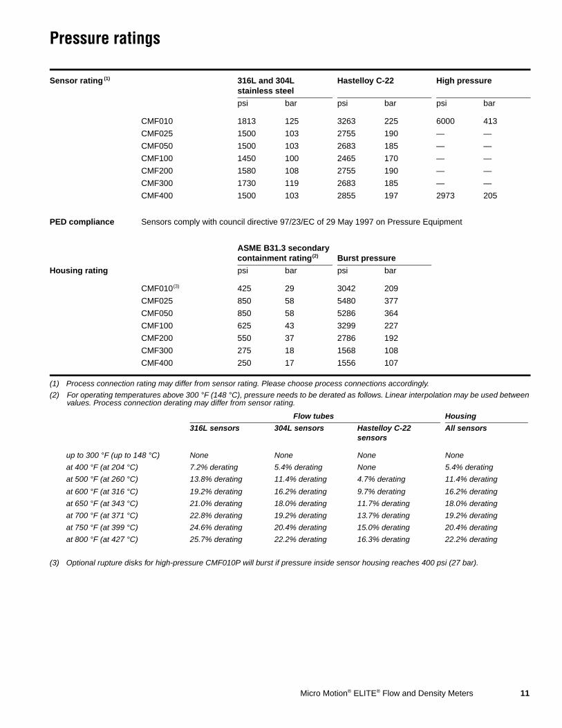
Sensor rating (1)
(1) Process connection rating may differ from sensor rating. Please choose process connections accordingly.
316L and 304L stainless steel
Hastelloy C-22 High pressure
psi bar psi bar psi bar
CMF010 1813 125 3263 225 6000 413
CMF025 1500 103 2755 190 — —
CMF050 1500 103 2683 185 — —
CMF100 1450 100 2465 170 — —
CMF200 1580 108 2755 190 — —
CMF300 1730 119 2683 185 — —
CMF400 1500 103 2855 197 2973 205
PED compliance Sensors comply with council directive 97/23/EC of 29 May 1997 on Pressure Equipment
ASME B31.3 secondarycontainment rating(2)
(2) For operating temperatures above 300 °F (148 °C), pressure needs to be derated as follows. Linear interpolation may be used between values. Process connection derating may differ from sensor rating.
Burst pressure
Housing rating psi bar psi bar
CMF010(3)
(3) Optional rupture disks for high-pressure CMF010P will burst if pressure inside sensor housing reaches 400 psi (27 bar).
425 29 3042 209
CMF025 850 58 5480 377
CMF050 850 58 5286 364
CMF100 625 43 3299 227
CMF200 550 37 2786 192
CMF300 275 18 1568 108
CMF400 250 17 1556 107
Flow tubes Housing
316L sensors 304L sensors Hastelloy C-22 sensors
All sensors
up to 300 °F (up to 148 °C) None None None None
at 400 °F (at 204 °C) 7.2% derating 5.4% derating None 5.4% derating
at 500 °F (at 260 °C) 13.8% derating 11.4% derating 4.7% derating 11.4% derating
at 600 °F (at 316 °C) 19.2% derating 16.2% derating 9.7% derating 16.2% derating
at 650 °F (at 343 °C) 21.0% derating 18.0% derating 11.7% derating 18.0% derating
at 700 °F (at 371 °C) 22.8% derating 19.2% derating 13.7% derating 19.2% derating
at 750 °F (at 399 °C) 24.6% derating 20.4% derating 15.0% derating 20.4% derating
at 800 °F (at 427 °C) 25.7% derating 22.2% derating 16.3% derating 22.2% derating
12 Micro Motion® ELITE® Flow and Density Meters
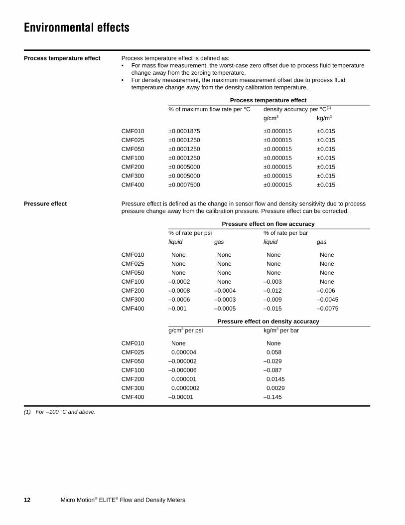
Environmental effects
Process temperature effect Process temperature effect is defined as:• For mass flow measurement, the worst-case zero offset due to process fluid temperature
change away from the zeroing temperature.• For density measurement, the maximum measurement offset due to process fluid
temperature change away from the density calibration temperature.
Process temperature effect
% of maximum flow rate per °C density accuracy per °C(1)
(1) For –100 °C and above.
g/cm3 kg/m3
CMF010 ±0.0001875 ±0.000015 ±0.015
CMF025 ±0.0001250 ±0.000015 ±0.015
CMF050 ±0.0001250 ±0.000015 ±0.015
CMF100 ±0.0001250 ±0.000015 ±0.015
CMF200 ±0.0005000 ±0.000015 ±0.015
CMF300 ±0.0005000 ±0.000015 ±0.015
CMF400 ±0.0007500 ±0.000015 ±0.015
Pressure effect Pressure effect is defined as the change in sensor flow and density sensitivity due to process pressure change away from the calibration pressure. Pressure effect can be corrected.
Pressure effect on flow accuracy
% of rate per psi % of rate per bar
liquid gas liquid gas
CMF010 None None None None
CMF025 None None None None
CMF050 None None None None
CMF100 –0.0002 None –0.003 None
CMF200 –0.0008 –0.0004 –0.012 –0.006
CMF300 –0.0006 –0.0003 –0.009 –0.0045
CMF400 –0.001 –0.0005 –0.015 –0.0075
Pressure effect on density accuracy
g/cm3 per psi kg/m3 per bar
CMF010 None None
CMF025 0.000004 0.058
CMF050 –0.000002 –0.029
CMF100 –0.000006 –0.087
CMF200 0.000001 0.0145
CMF300 0.0000002 0.0029
CMF400 –0.00001 –0.145

Micro Motion® ELITE® Flow and Density Meters 13
Hazardous area classifications
UL(1)
(1) The following products are not available with UL approval: sensors with enhanced core processor or Model 2400S transmitter; high-temperature sensors; extreme high-temperature sensors.
All models with core processor Ambient temperature: –40 °F (–40 °C) to +104 °F (+40 °C)
Class I, Div. 1, Groups C and D
Class I, Div. 2, Groups A, B, C, and D
Class II, Div.1, Groups E, F, and G
All models with junction box Ambient temperature: +104 °F (+40 °C) maximum
Class I, Div. 1, Groups C and D
Class I, Div. 2, Groups A, B, C, and D
Class II, Div.1, Groups E, F, and G
CSA and CSA C-US(2)
(2) The following products are available only with CSA C-US approval (i.e., not CSA): sensors with enhanced core processor or Model 2400S transmitter; high-temperature sensors; extreme high-temperature sensors.
All models with Model 2400S transmitter Ambient temperature: –40 °F (–40 °C) to +140 °F (+60 °C)
Class I, Div 2, Groups A, B, C and D
All models with core processor or enhanced core processor
Ambient temperature: –40 °F (–40 °C) to +140 °F (+60 °C)
Class I, Div. 1, Groups C and D
Class I, Div. 2, Groups A, B, C, and D
Class II, Div.1, Groups E, F, and G
All models with junction box Ambient temperature: +140 °F (+60 °C) maximum
Class I, Div. 1, Groups C and D
Class I, Div. 2, Groups A, B, C, and D
Class II, Div.1, Groups E, F, and G
ATEX, IECEx, and NEPSI
All models with Model 2400S transmitter
IECEx and NEPSI Ex nA II T(3)
(3) For ambient and process temperature limits, refer to the temperature graphs on pages 14–17.
ATEX II 3G Ex nA II T(3) °C
II 3D IP65 T(3) °C
CMF010, CMF025, CMF050, and CMF100
IECEx and NEPSI Ex ib IIC T(3)
ATEX II 2G EEx ib IIC T(3) °C
II 2D IP65 T(3) °C
CMF200, CMF300, and CMF400
IECEx and NEPSI Ex ib IIB T(3)
ATEX II 2G EEx ib IIB T(3) °C
II 2D IP65 T(3) °C

14 Micro Motion® ELITE® Flow and Density Meters
Hazardous area classifications continued
CMF010, CMF025, or CMF050 with junction box connected to MVD transmitter
Use the above graph to determine the temperature class for a given fluid and ambient temperature. The maximum surface temperature for dust is as follows: T6:T 80 °C, T5:T 95 °C, T4:T 130 °C, T3:T 195 °C, T2 to T1:T 254 °C. The minimum ambient and process fluid temperature allowed for dust is –40 °C.The use of the sensor at an ambient temperature higher than +55 °C is possible, provided that the ambient temperature does not exceed the maximum temperature of the medium taking into account the temperature classification and the maximum operating temperature of the sensor.
Ambient temperature range Ta –240 °C to +55 °C
CMF100 with junction box connected to MVD transmitter
Use the above graph to determine the temperature class for a given fluid and ambient temperature. The maximum surface temperature for dust is as follows: T6:T 80 °C, T5:T 95 °C, T4:T 130 °C, T3:T 195 °C, T2 to T1:T 254 °C. The minimum ambient and process fluid temperature allowed for dust is –40 °C. The use of the sensor at an ambient temperature higher than +55 °C is possible, provided that the ambient temperature does not exceed the maximum temperature of the medium taking into account the temperature classification and the maximum operating temperature of the sensor.
Ambient temperature range Ta –60 °C to +55 °C
Sensor fluid temp (°C)
Max
am
bien
t tem
p (°
C)
Sensor fluid temp (°C)
Max
am
bien
t tem
p (°
C)
Micro Motion® ELITE® Flow and Density Meters 15
Hazardous area classifications continued
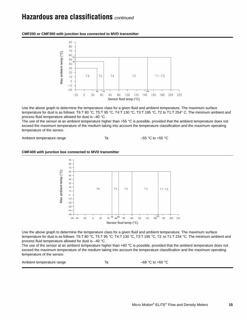
CMF200 or CMF300 with junction box connected to MVD transmitter
Use the above graph to determine the temperature class for a given fluid and ambient temperature. The maximum surface temperature for dust is as follows: T6:T 80 °C, T5:T 95 °C, T4:T 130 °C, T3:T 195 °C, T2 to T1:T 254° C. The minimum ambient and process fluid temperature allowed for dust is –40 °C.The use of the sensor at an ambient temperature higher than +55 °C is possible, provided that the ambient temperature does not exceed the maximum temperature of the medium taking into account the temperature classification and the maximum operating temperature of the sensor.
Ambient temperature range Ta –55 °C to +55 °C
CMF400 with junction box connected to MVD transmitter
Use the above graph to determine the temperature class for a given fluid and ambient temperature. The maximum surface temperature for dust is as follows: T6:T 80 °C, T5:T 95 °C, T4:T 130 °C, T3:T 195 °C, T2: to T1:T 234 °C. The minimum ambient and process fluid temperature allowed for dust is –40 °C.The use of the sensor at an ambient temperature higher than +60 °C is possible, provided that the ambient temperature does not exceed the maximum temperature of the medium taking into account the temperature classification and the maximum operating temperature of the sensor.
Ambient temperature range Ta –68 °C to +60 °C
Sensor fluid temp (°C)
Max
am
bien
t tem
p (°
C)
Sensor fluid temp (°C)
Max
am
bien
t tem
p (°
C)

16 Micro Motion® ELITE® Flow and Density Meters
Hazardous area classifications continued
CMF200A, CMF300A, or CMF400A with junction box connected to MVD transmitter
Use the above graph to determine the temperature class for a given fluid and ambient temperature. The maximum surface temperature for dust is as follows: T6:T 80 °C, T5:T 95 °C, T4:T 130 °C, T3:T 195 °C, T2:T 290 °C, T1:T 363 °C. The minimum ambient and process fluid temperature allowed for dust is –40 °C.The use of the sensor at an ambient temperature higher than +55°C is possible, provided that the ambient temperature does not exceed the maximum temperature of the medium taking into account the temperature classification and the maximum operating temperature of the sensor.
Ambient temperature range Ta –50 °C to +55 °C
CMF010, CMF025, CMF050, CMF100, CMF200 or CMF300 with core processor or enhanced core processor
Use the above graph to determine the temperature class for a given fluid and ambient temperature. The maximum surface temperature for dust is as follows: T5:T 95°C, T4:T 130°C, T3:T 195°C, T2 to T1:T 254°C.
Ambient temperature range Ta –40 °C to +55 °C
Sensor fluid temp (°C)
Max
am
bien
t tem
p (°
C)
Sensor fluid temp (°C)
Max
am
bien
t tem
p (°
C)
De-rate at slope = –0.093 ambient per °C fluid
Micro Motion® ELITE® Flow and Density Meters 17
Hazardous area classifications continued
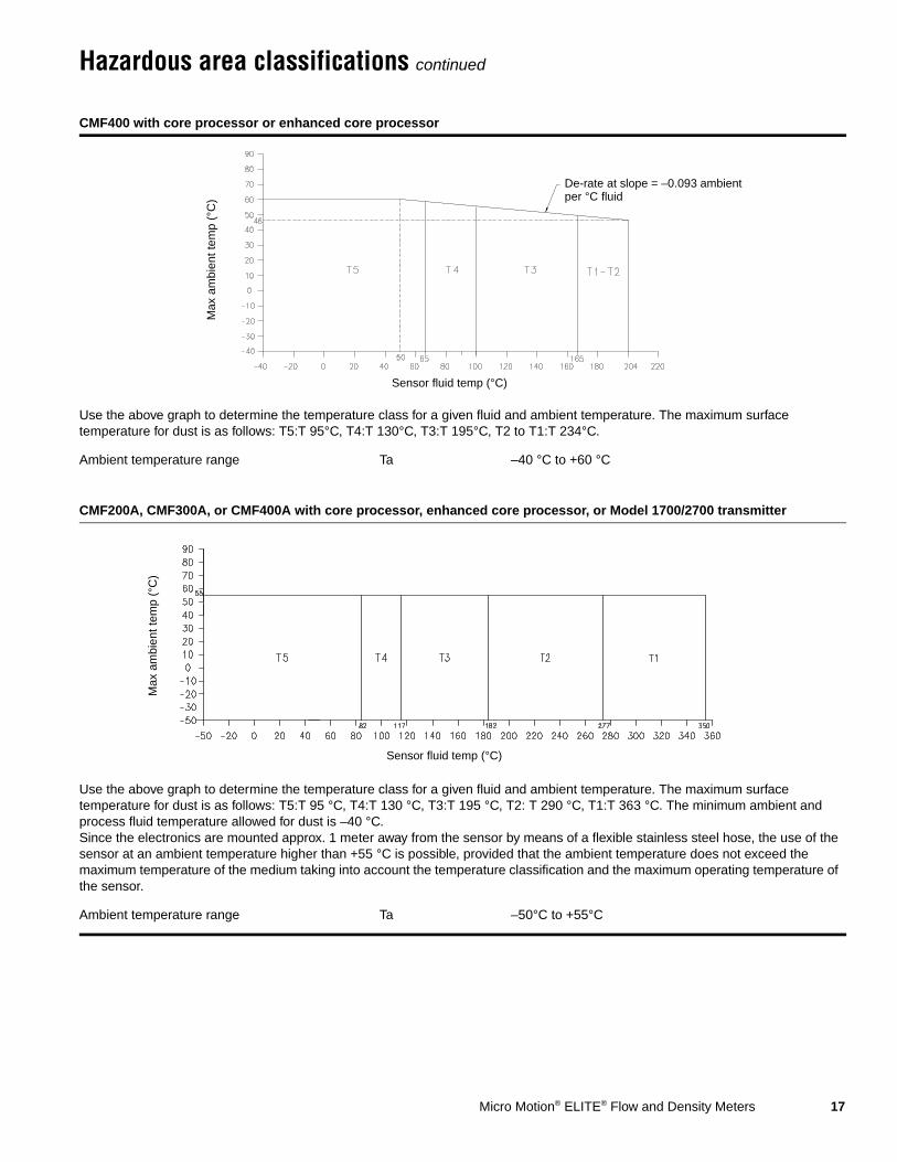
CMF400 with core processor or enhanced core processor
Use the above graph to determine the temperature class for a given fluid and ambient temperature. The maximum surface temperature for dust is as follows: T5:T 95°C, T4:T 130°C, T3:T 195°C, T2 to T1:T 234°C.
Ambient temperature range Ta –40 °C to +60 °C
CMF200A, CMF300A, or CMF400A with core processor, enhanced core processor, or Model 1700/2700 transmitter
Use the above graph to determine the temperature class for a given fluid and ambient temperature. The maximum surface temperature for dust is as follows: T5:T 95 °C, T4:T 130 °C, T3:T 195 °C, T2: T 290 °C, T1:T 363 °C. The minimum ambient and process fluid temperature allowed for dust is –40 °C.Since the electronics are mounted approx. 1 meter away from the sensor by means of a flexible stainless steel hose, the use of the sensor at an ambient temperature higher than +55 °C is possible, provided that the ambient temperature does not exceed the maximum temperature of the medium taking into account the temperature classification and the maximum operating temperature of the sensor.
Ambient temperature range Ta –50°C to +55°C
Sensor fluid temp (°C)
Max
am
bien
t tem
p (°
C)
De-rate at slope = –0.093 ambient per °C fluid
Sensor fluid temp (°C)
Max
am
bien
t tem
p (°
C)
18 Micro Motion® ELITE® Flow and Density Meters
Materials of construction
Weight
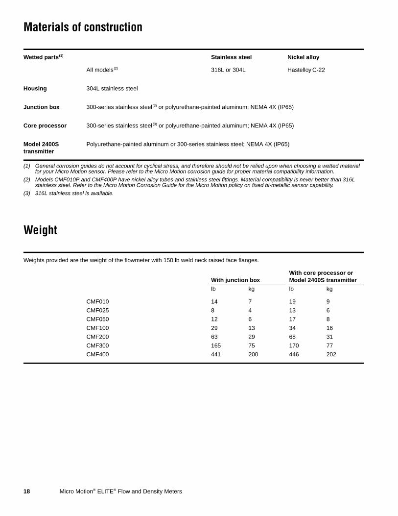
Wetted parts(1)
(1) General corrosion guides do not account for cyclical stress, and therefore should not be relied upon when choosing a wetted material for your Micro Motion sensor. Please refer to the Micro Motion corrosion guide for proper material compatibility information.
Stainless steel Nickel alloy
All models(2)
(2) Models CMF010P and CMF400P have nickel alloy tubes and stainless steel fittings. Material compatibility is never better than 316L stainless steel. Refer to the Micro Motion Corrosion Guide for the Micro Motion policy on fixed bi-metallic sensor capability.
316L or 304L Hastelloy C-22
Housing 304L stainless steel
Junction box 300-series stainless steel(3) or polyurethane-painted aluminum; NEMA 4X (IP65)
(3) 316L stainless steel is available.
Core processor 300-series stainless steel (3) or polyurethane-painted aluminum; NEMA 4X (IP65)
Model 2400S transmitter
Polyurethane-painted aluminum or 300-series stainless steel; NEMA 4X (IP65)
Weights provided are the weight of the flowmeter with 150 lb weld neck raised face flanges.
With junction boxWith core processor or Model 2400S transmitter
lb kg lb kg
CMF010 14 7 19 9
CMF025 8 4 13 6
CMF050 12 6 17 8
CMF100 29 13 34 16
CMF200 63 29 68 31
CMF300 165 75 170 77
CMF400 441 200 446 202
Micro Motion® ELITE® Flow and Density Meters 19
Dimensions
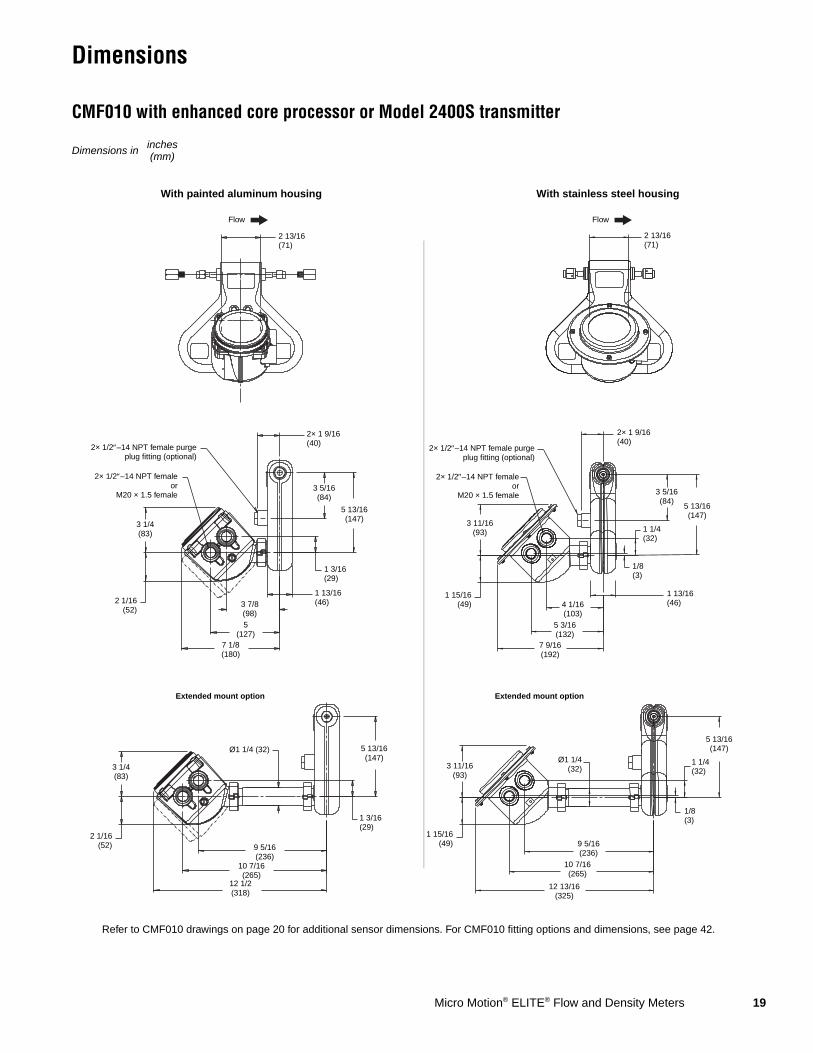
CMF010 with enhanced core processor or Model 2400S transmitter
Dimensions in inches(mm)
2 13/16(71)
3 11/16(93)
1 15/16(49) 4 1/16
(103)5 3/16(132)
7 9/16(192)
1 13/16(46)
1 1/4(32)
5 13/16(147)
2× 1 9/16(40)
3 5/16(84)
Refer to CMF010 drawings on page 20 for additional sensor dimensions. For CMF010 fitting options and dimensions, see page 42.
1/8(3)
5 13/16(147)
Ø1 1/4(32)
9 5/16(236)
10 7/16(265)
12 13/16(325)
3 11/16(93)
1 15/16(49)
Extended mount option
Flow
With painted aluminum housing With stainless steel housing
Flow
2 13/16(71)
3 1/4(83)
2 1/16(52)
2× 1/2″–14 NPT femaleor
M20 × 1.5 female
2× 1/2″–14 NPT female purgeplug fitting (optional)
3 7/8(98)5
(127)7 1/8(180)
1 13/16(46)
1 3/16(29)
5 13/16(147)
2× 1 9/16(40)
3 5/16(84)
1 3/16(29)
5 13/16(147)
Ø1 1/4 (32)
9 5/16(236)
10 7/16(265)
12 1/2(318)
3 1/4(83)
2 1/16(52)
2× 1/2″–14 NPT femaleor
M20 × 1.5 female
2× 1/2″–14 NPT female purgeplug fitting (optional)
1/8(3)
1 1/4(32)
Extended mount option
20 Micro Motion® ELITE® Flow and Density Meters
Dimensions continued
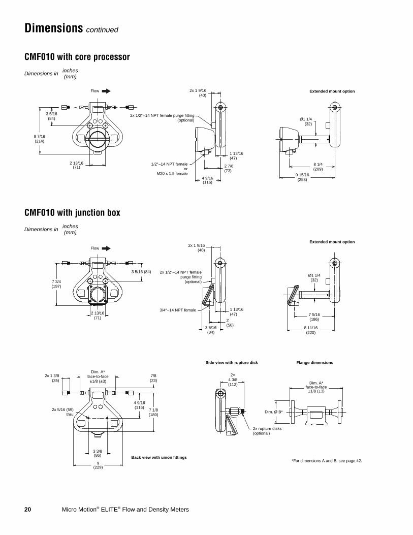
CMF010 with core processor
CMF010 with junction box
3 5/16(84)
2 13/16(71)
2x 1 9/16(40)
2x 1/2″–14 NPT female purge fitting(optional)
1/2″–14 NPT femaleor
M20 x 1.5 female4 9/16(116)
Ø1 1/4(32)
8 1/4(209)
9 15/16(253)
Extended mount option
2 7/8(73)
1 13/16(47)
Dimensions in inches(mm)
8 7/16(214)
Flow
3 5/16 (84)
2 13/16(71)
2x 1 9/16(40)
2x 1/2″–14 NPT femalepurge fitting
(optional)
3/4″–14 NPT female
3 5/16(84)
2(50)
1 13/16(47)
Ø1 1/4(32)
7 5/16(186)
8 11/16(220)
Extended mount option
Back view with union fittings
Flange dimensionsSide view with rupture disk
2x 1 3/8(35)
2x 5/16 (59)thru
Dim. A*face-to-face
±1/8 (±3)7/8(23)
3 3/8(86)
9(229)
2×4 3/8(112)
2x rupture disks(optional)
Dim. A*face-to-face
±1/8 (±3)
Dim. Ø B*
*For dimensions A and B, see page 42.
Dimensions in inches(mm)
7 3/4(197)
4 9/16(116)
7 1/8(180)
Flow
Micro Motion® ELITE® Flow and Density Meters 21
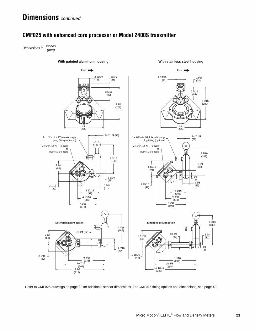
Dimensions continued
CMF025 with enhanced core processor or Model 2400S transmitter
Dimensions in inches(mm)
2 13/16(71)
3 11/16(93)
1 15/16(49)
4 1/16(103)
5 3/16(132)
7 9/16(192)
1 5/8 (41)
1 1/4(32)
7 7/16(188)
2× 2 1/4(58)
15/16(24)
1/8(3)
7 7/16(188)
Ø1 1/4(32)
9 5/16(236)
10 3/8(264)12 13/16
(325)
3 11/16(93)
1 15/16(49)
Extended mount option
Flow
With painted aluminum housing With stainless steel housing
Flow
2 13/16(71)
3 1/4(83)
2 1/16(52)
2× 1/2″–14 NPT femaleor
M20 × 1.5 female
2× 1/2″–14 NPT female purgeplug fitting (optional)
3 13/16(97)
4 15/16(126)
7 1/16(179)
1 5/8(41)
1 3/16(29)
7 7/16(188)
2× 2 1/4 (58)
8 1/4(209)
1 3/16(29)
Ø1 1/4 (32)
9 5/16(236)
10 7/16(265)
12 1/2(318)
3 1/4(83)
2 1/16(52)
2× 1/2″–14 NPT femaleor
M20 × 1.5 female
2× 1/2″–14 NPT female purgeplug fitting (optional)
1/8(3)
1 1/4(32)
Refer to CMF025 drawings on page 22 for additional sensor dimensions. For CMF025 fitting options and dimensions, see page 43.
15/16(24)
10(255)
3 5/16(85)
10(255)
3 5/16(85)
8 3/16(209)
Extended mount option
7 7/16(188)

22 Micro Motion® ELITE® Flow and Density Meters
Dimensions continued
CMF025 with core processor
CMF025 with junction box
Extended mount option
10 1/16(255)
3 5/16(84)
2 13/16(72)
2x 2 1/4(58)
2x 1/2″–14 NPT femalepurge fitting
(optional)
1/2″–14 NPT femaleor
M20 x 1.5 female
1 5/8(41)
2 15/16(75)
4 11/16(119)
Ø1 1/4(32)
10 1/16(256)
8 5/16(212)
Dimensions in inches(mm)
10(255)
15/16(24)
8 1/4(209)
Flow
Ø1 1/4(32)
7 7/16(190)
8 3/4(223)
2 13/16(72)
2x 1/2″–14 NPT femalepurge fitting
(optional)
3/4″–14 NPT female
2x 2 1/4(58)
1 5/8(41)
2 1/16(53)
3 7/16(87)
Dim. A*face to face±1/8 (±3)
Dim. A* ±1/8(±3)
Union detail
Flange detail
15/16(24)
Dim. Ø B*
10(255)
1/2″–14 NPT female
2× 1 3/4(45)
Dim. B*
Dim. A*face to face±1/8 (±3)
*For dimensions A and B, see page 43.
Dimensions in inches(mm)
3 5/16(84)
8 1/4(209)
Extended mount option
9 11/16(246)
Flow
Wafer detail

Micro Motion® ELITE® Flow and Density Meters 23
Dimensions continued
CMF050 with enhanced core processor or Model 2400S transmitter
Dimensions in inches(mm)
Refer to CMF050 drawings on page 24 for additional sensor dimensions. For CMF050 fitting options and dimensions, see page 44.
5(126)
11 1/16(280)
2 1/16(52)
2× 1/2″–14 NPT femaleor
M20 × 1.5 female
2× 1/2″–14 NPT female purgeplug fitting (optional)
4 1/16(103)
5 3/16(132)
7 5/16(185)
2(51)
1 3/16(29)
10 1/16(255)
2× 2 1/2 (63)
1 3/16(29)
10 1/16(255)
Ø1 1/4 (32)
9 7/16(240)
10 9/16(268)
12 11/16(322)
3 1/4(83)
2 1/16(52)
15/16(24)
14 5/16(364)
3 1/4 (82)
Flow
Extended mount option
With painted aluminum housing With stainless steel housing
Flow
4 3/8(111)
5(126)
11 1/16(280)
15/16(24)
4 3/8(111)
14 5/16(364)
1 15/16(49)
2× 1/2″–14 NPT femaleor
M20 × 1.5 female
2× 1/2″–14 NPT femalepurge plug fitting
(optional)
4(102)
5 1/8(130)
7 9/16(191)
2(51)
1 1/4(32)
10 1/16(255)
2× 2 1/2 (63)
3 11/16 (93)
1/8 (3)
1/8(3)
10 1/16(255)
Ø1 1/4 (32)
9 1/4(235)
10 3/8(263)
12 3/4(324)
3 11/16(93)
1 15/16(49)
1 1/4(32)
Extended mount option
24 Micro Motion® ELITE® Flow and Density Meters
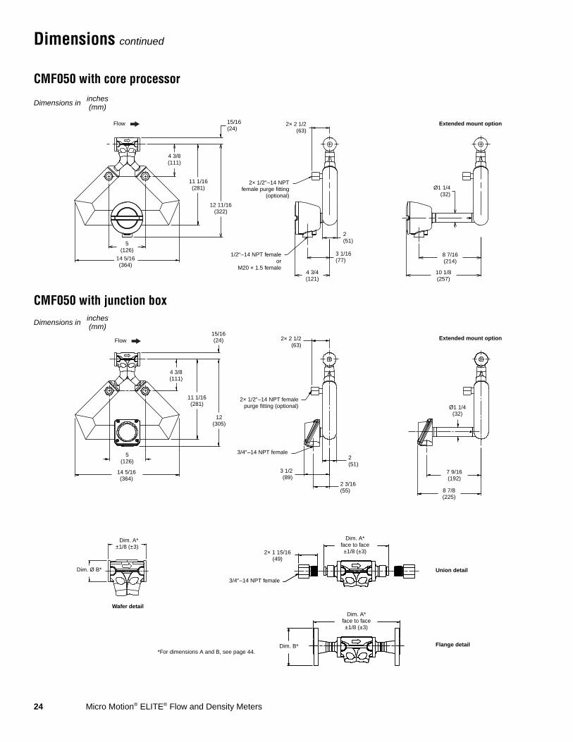
Dimensions continued
CMF050 with core processor
CMF050 with junction box
5(126)
2× 1/2″–14 NPTfemale purge fitting
(optional)
2× 2 1/2(63)
1/2″–14 NPT femaleor
M20 × 1.5 female4 3/4(121)
3 1/16(77)
2(51)
Ø1 1/4(32)
8 7/16(214)
10 1/8(257)
Extended mount option
14 5/16(364)
Dimensions in inches(mm)
12 11/16(322)
4 3/8(111)
15/16(24)
11 1/16(281)
Flow
Ø1 1/4(32)
7 9/16(192)
8 7/8(225)
2× 1/2″–14 NPT femalepurge fitting (optional)
3/4″–14 NPT female
12(305)
4 3/8(111)
5(126)
2× 2 1/2(63)
3 1/2(89)
2(51)
2 3/16(55)
Dim. A*face to face±1/8 (±3)
Union detail
Flange detail
Dim. A*±1/8 (±3)
Dim. Ø B*
15/16(24)
11 1/16(281)
3/4″–14 NPT female
2× 1 15/16(49)
Dim. B*
Dim. A*face to face±1/8 (±3)
*For dimensions A and B, see page 44.
Dimensions in inches(mm)
Extended mount option
14 5/16(364)
Flow
Wafer detail
Micro Motion® ELITE® Flow and Density Meters 25
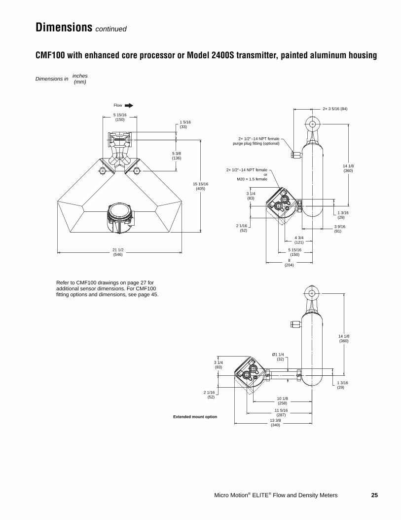
Dimensions continued
CMF100 with enhanced core processor or Model 2400S transmitter, painted aluminum housing
Dimensions in inches(mm)
5 15/16(150)
1 5/16(33)
15 15/16(405)
5 3/8(136)
21 1/2(546)
2× 1/2″–14 NPT femaleor
M20 × 1.5 female
2× 1/2″–14 NPT femalepurge plug fitting (optional)
2× 3 5/16 (84)
14 1/8(360)
1 3/16(29)
3 9/16(91)
3 1/4(83)
2 1/16(52)
4 3/4(121)
5 15/16(150)
8(204)
3 1/4(83)
2 1/16(52)
Ø1 1/4(32)
10 1/8(258)
11 5/16(287)
13 3/8(340)
1 3/16(29)
14 1/8(360)
Refer to CMF100 drawings on page 27 for additional sensor dimensions. For CMF100 fitting options and dimensions, see page 45.
Extended mount option
Flow
26 Micro Motion® ELITE® Flow and Density Meters
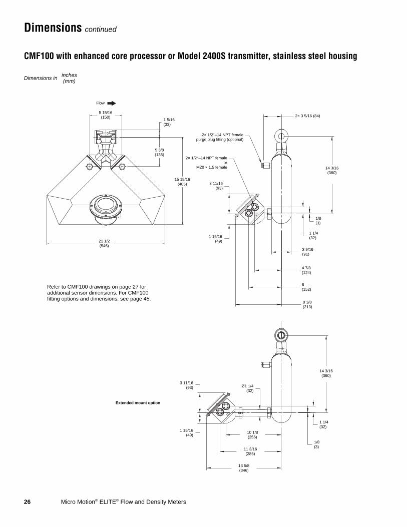
Dimensions continued
CMF100 with enhanced core processor or Model 2400S transmitter, stainless steel housing
Refer to CMF100 drawings on page 27 for additional sensor dimensions. For CMF100 fitting options and dimensions, see page 45.
Extended mount option
5 15/16(150)
15 15/16(405)
1 15/16(49)
2× 1/2″–14 NPT femaleor
M20 × 1.5 female
2× 1/2″–14 NPT femalepurge plug fitting (optional)
4 7/8(124)
6(152)
8 3/8(213)
3 9/16(91)
1/8(3)
14 3/16(360)
2× 3 5/16 (84)
5 3/8(136)
1 1/4(32)
14 3/16(360)
Ø1 1/4(32)
10 1/8(256)
11 3/16(285)
13 5/8(346)
3 11/16(93)
1 15/16(49)
1 5/16(33)
21 1/2(546)
3 11/16(93)
Flow
1 1/4(32)
1/8(3)
Dimensions in inches(mm)
Micro Motion® ELITE® Flow and Density Meters 27
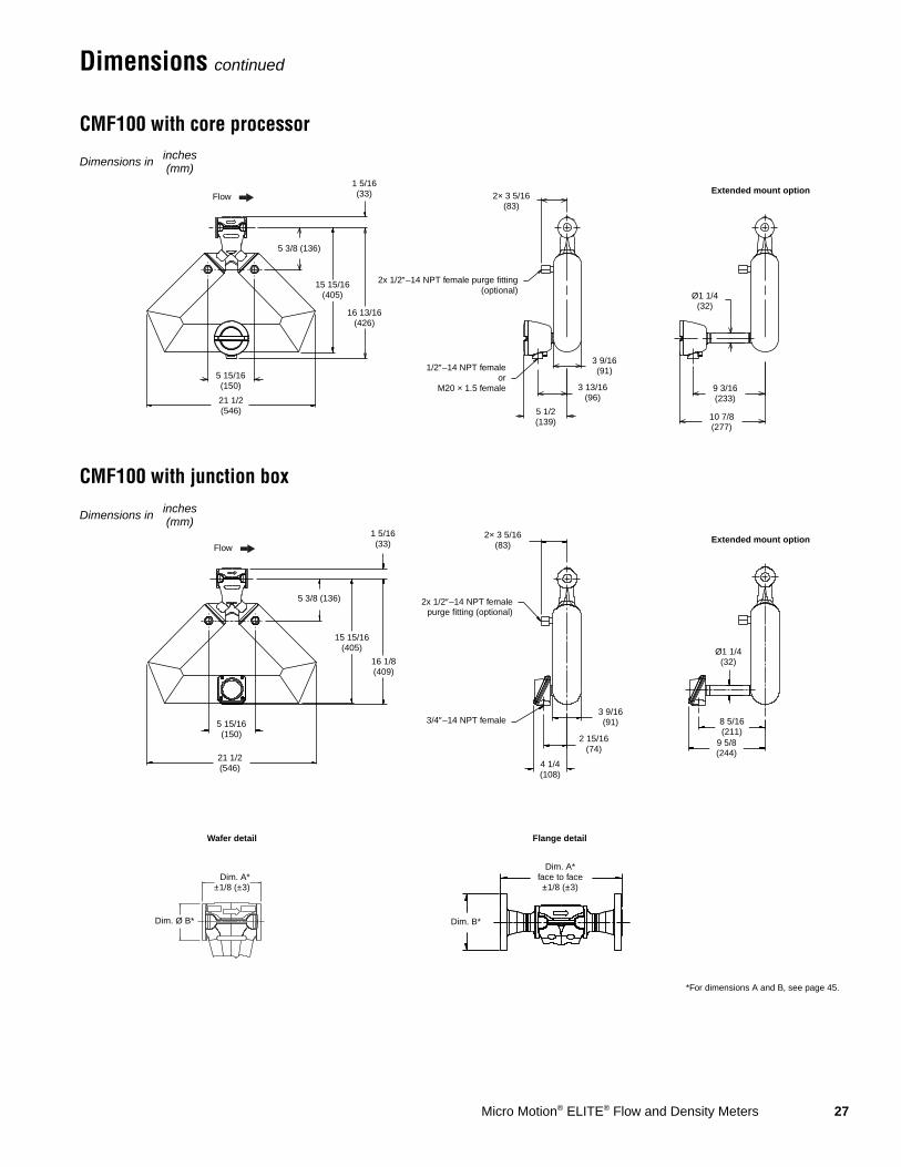
Dimensions continued
CMF100 with core processor
CMF100 with junction box
5 3/8 (136)
1/2″–14 NPT femaleor
M20 × 1.5 female
2× 3 5/16(83)
2x 1/2″–14 NPT female purge fitting(optional)
5 1/2(139)
3 13/16(96)
3 9/16(91)
10 7/8(277)
9 3/16(233)
Ø1 1/4(32)
Extended mount option
5 15/16(150)
Dimensions in inches(mm)
16 13/16(426)
1 5/16(33)
21 1/2(546)
15 15/16(405)
Flow
Extended mount option
Ø1 1/4(32)
3/4″–14 NPT female
5 3/8 (136) 2x 1/2″–14 NPT femalepurge fitting (optional)
2× 3 5/16(83)
5 15/16(150)
4 1/4(108)
2 15/16(74)
3 9/16(91)
Dim. A*±1/8 (±3)
Flange detail
Dim. Ø B*
Dim. A*face to face±1/8 (±3)
1 5/16(33)
21 1/2(546)
Dim. B*
*For dimensions A and B, see page 45.
Dimensions in inches(mm)
9 5/8(244)
8 5/16(211)
15 15/16(405)
16 1/8(409)
Flow
Wafer detail

28 Micro Motion® ELITE® Flow and Density Meters
Dimensions continued
CMF200 with enhanced core processor or Model 2400S transmitter, painted aluminum housing
Dimensions in inches(mm)
Refer to CMF200 drawings on page 30 for additional sensor dimensions. For dimensions A and B, see CMF200 fitting options and dimensions on page 46.
Dim Ø “B”
2 1/16 (52)
2× 1/2″–14 NPT femaleor
M20 × 1.5 female
2× 1/2″–14 NPT femalepurge plug fitting
(optional)
1 1/2(38)
Dim “A” ±1/8″(±3)
11 7/8(302)
28 5/8(727)
7(178)
14(356)
19 9/16(497)
3 1/4 (83)
5 7/8(150)
7(178)
9 1/8(232)
6 7/8(175)
1 3/16(29)
5 9/16(142)
2× 4 5/16(110)
14 1/2(368)
12 3/8(315)
11 1/4(286)
Ø1 1/4(32)
6 7/8(175)
1 3/16(29)
3 1/4(83)
2 1/16(52)
Extended mount option
Flow
Micro Motion® ELITE® Flow and Density Meters 29
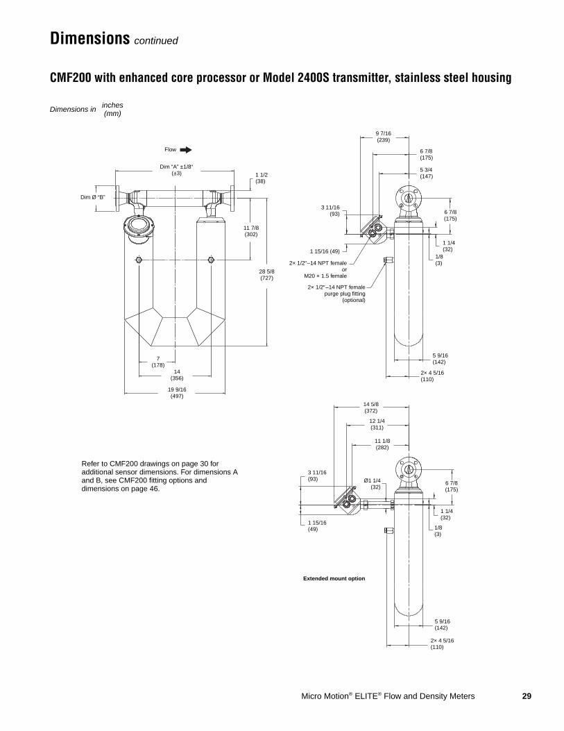
Dimensions continued
CMF200 with enhanced core processor or Model 2400S transmitter, stainless steel housing
Dimensions in inches(mm)
Refer to CMF200 drawings on page 30 for additional sensor dimensions. For dimensions A and B, see CMF200 fitting options and dimensions on page 46.
Dim Ø “B”
1 15/16 (49)
2× 1/2″–14 NPT femaleor
M20 × 1.5 female
2× 1/2″–14 NPT femalepurge plug fitting
(optional)
1 1/2(38)
Dim “A” ±1/8″(±3)
11 7/8(302)
28 5/8(727)
7(178)
14(356)
19 9/16(497)
3 11/16(93)
6 7/8(175)
9 7/16(239)
6 7/8(175)
1 1/4(32)
5 9/16(142)
2× 4 5/16(110)
14 5/8(372)
12 1/4(311)
11 1/8(282)
Ø1 1/4(32)
6 7/8(175)
1 1/4(32)
3 11/16(93)
1 15/16(49)
Extended mount option
Flow
5 3/4(147)
1/8(3)
1/8(3)
5 9/16(142)
2× 4 5/16(110)
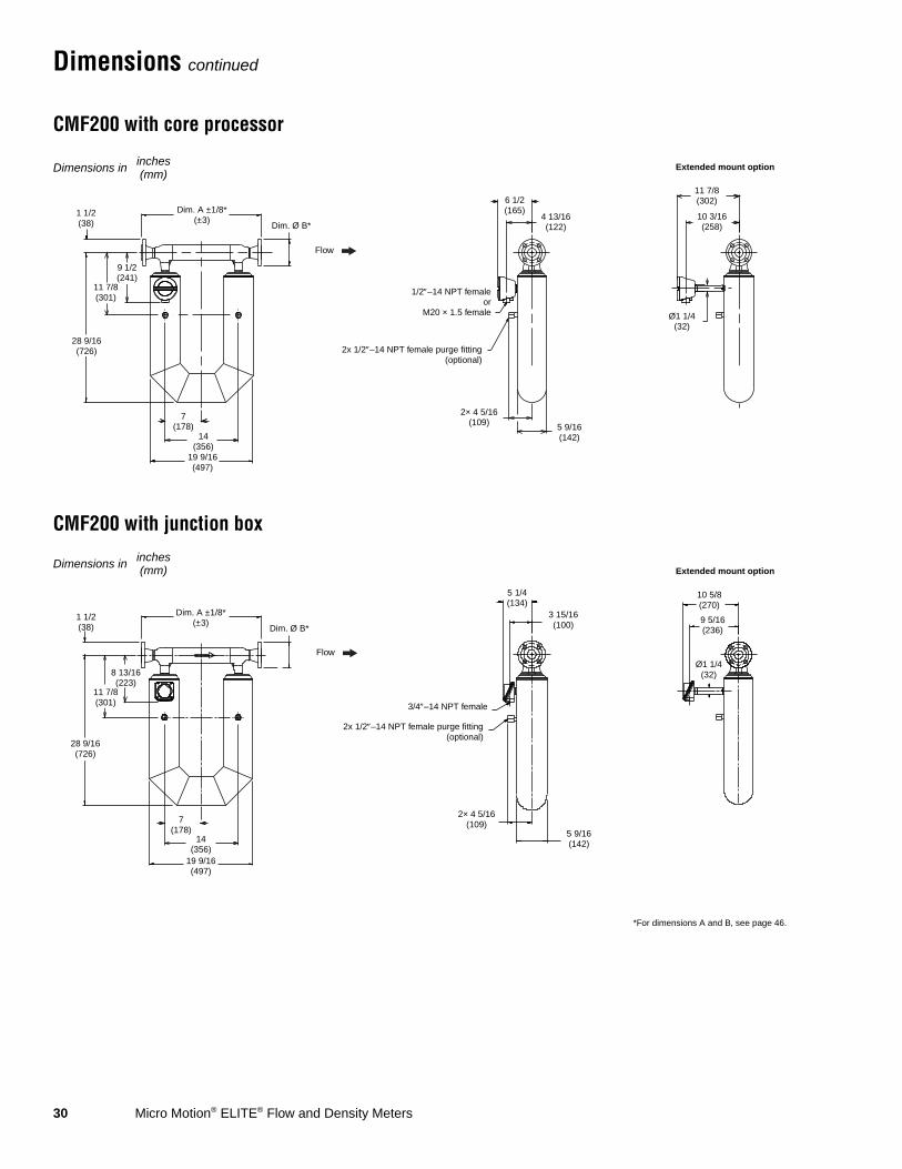
30 Micro Motion® ELITE® Flow and Density Meters
Dimensions continued
CMF200 with core processor
CMF200 with junction box
Extended mount option
1/2″–14 NPT femaleor
M20 × 1.5 female
5 9/16(142)
2x 1/2″–14 NPT female purge fitting(optional)
7(178)
14(356)
4 13/16(122)
6 1/2(165)
11 7/8(302)
10 3/16(258)
Ø1 1/4(32)
2× 4 5/16(109)
9 1/2 (241)
11 7/8 (301)
Dimensions in inches(mm)
Dim. A ±1/8*(±3)
1 1/2(38)
19 9/16(497)
Dim. Ø B*
28 9/16(726)
Flow
Dim. A ±1/8*(±3)
1 1/2(38)
19 9/16(497)
Ø1 1/4(32)
10 5/8(270)
9 5/16(236)
5 1/4(134)
3 15/16(100)
5 9/16(142)
2× 4 5/16(109)
2x 1/2″–14 NPT female purge fitting(optional)
3/4″–14 NPT female
7(178)
14(356)
Extended mount option
*For dimensions A and B, see page 46.
Dim. Ø B*
Dimensions in inches(mm)
8 13/16(223)
11 7/8(301)
28 9/16(726)
Flow

Micro Motion® ELITE® Flow and Density Meters 31
Dimensions continued
CMF300 with enhanced core processor or Model 2400S transmitter, painted aluminum housing
Dimensions in inches(mm)
Refer to CMF300 drawings on page 33 for additional sensor dimensions. For dimensions A and B, see CMF300 fitting options and dimensions on page 48.
Dim Ø “B”
2 1/16 (52)
2× 1/2″–14 NPT femaleor
M20 × 1.5 female
2× 1/2″–14 NPT femalepurge plug fitting (optional)
3 5/16(84)
Dim “A” ±1/8″(±3)
13 7/8(352)
38 7/16(977)
11(279)
22(559)
30 3/16(767)
3 1/4 (83)
7 3/16(183)
8 5/16(212)
10 1/2(266)
9 3/8(238)
1 3/16(29)
8 3/16(209)
2× 5 5/8(143)
15 7/8(403)
Ø1 1/4(32)
9 3/8(238)
1 3/16(29)
3 1/4(83)
2 1/16(52)
Extended mount option
13 11/16(348)
12 9/16(320)
Flow
32 Micro Motion® ELITE® Flow and Density Meters
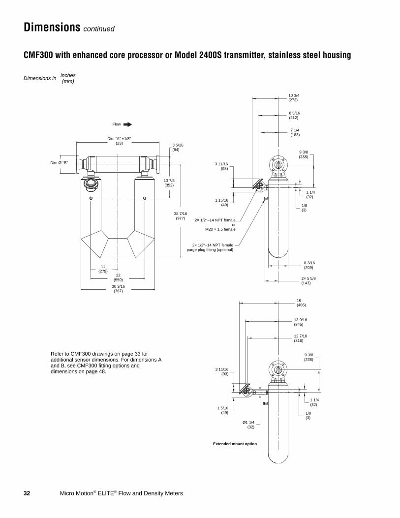
Dimensions continued
CMF300 with enhanced core processor or Model 2400S transmitter, stainless steel housing
Dimensions in inches(mm)
Refer to CMF300 drawings on page 33 for additional sensor dimensions. For dimensions A and B, see CMF300 fitting options and dimensions on page 48.
Dim Ø “B”
1 15/16(49)
2× 1/2″–14 NPT femaleor
M20 × 1.5 female
2× 1/2″–14 NPT femalepurge plug fitting (optional)
3 5/16(84)
Dim “A” ±1/8″(±3)
13 7/8(352)
38 7/16(977)
11(279)
22(559)
30 3/16(767)
7 1/4(183)
8 5/16(212)
10 3/4(273)
9 3/8(238)
8 3/16(209)
2× 5 5/8(143)
16(406)
Ø1 1/4(32)
9 3/8(238)
3 11/16(93)
1 5/16(49)
Extended mount option
13 9/16(345)
12 7/16(316)
Flow
3 11/16(93)
1 1/4(32)
1/8(3)
1 1/4(32)
1/8(3)

Micro Motion® ELITE® Flow and Density Meters 33
Dimensions continued
CMF300 with core processor
CMF300 with junction box
Extended mount option
1/2″–14 NPT femaleor
M20 × 1.5 female
2x 1/2″–14 NPT female purge fitting(optional)
11(279)
22(559)
2× 5 5/8(143)
8 3/16(208)
7 13/16(199) 6 1/8
(155)
13 3/16(335)11 1/2(292)
Ø1 1/4(32)
11 15/16 (303)13 13/16
(351)
Dimensions in inches(mm)
Dim. A ±1/8*(±3)
3 5/16(84)
30 3/16(767)
Dim. Ø B*
38 7/16(976)
Flow
11 15/16(303)
10 5/8(270)
Ø1 1/4(32)
11(279)
22(559)
6 9/16(167)
5 1/4(133)
2x 1/2″–14 NPT female purge fitting(optional)
2× 5 5/8(143)
8 3/16(208)
3/4″–14 NPT female
Dim. A ±1/8*(±3)
3 5/16(84)
30 3/16(767)
*For dimensions A and B, see page 48.
Dim. Ø B*
13 13/16 (351)
11 1/4 (286)
Dimensions in inches(mm)
Extended mount option
38 7/16(976)
Flow
34 Micro Motion® ELITE® Flow and Density Meters
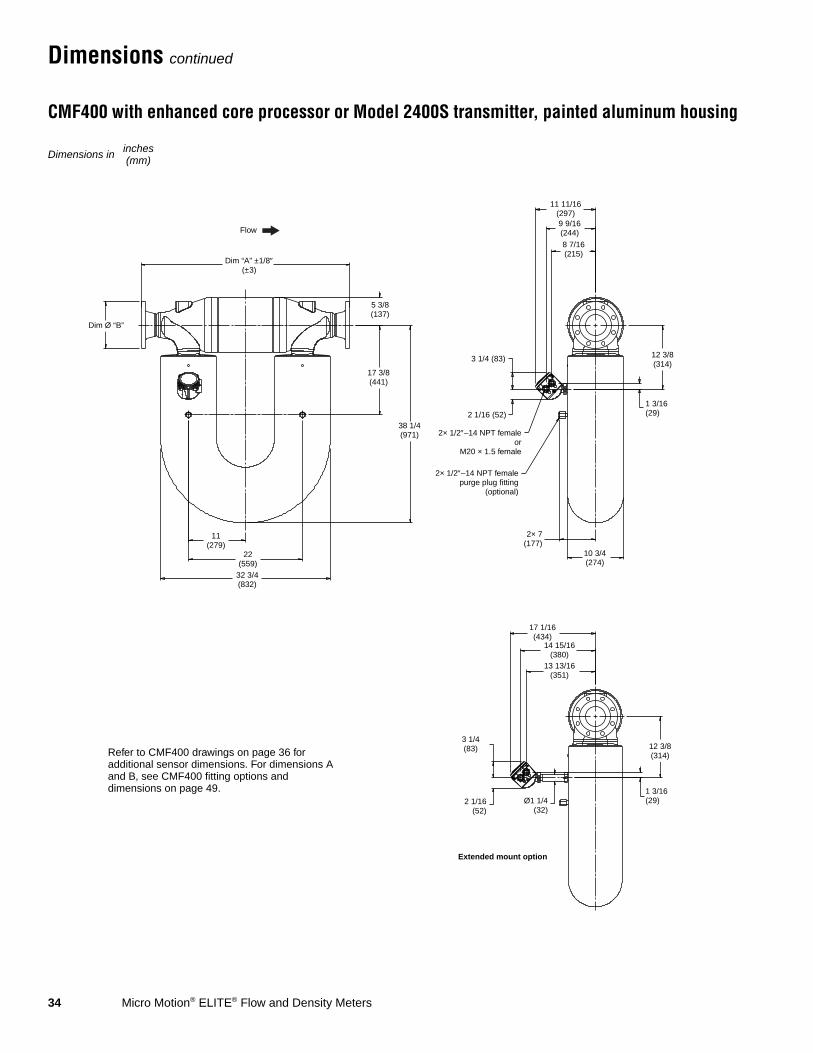
Dimensions continued
CMF400 with enhanced core processor or Model 2400S transmitter, painted aluminum housing
Dimensions in inches(mm)
Refer to CMF400 drawings on page 36 for additional sensor dimensions. For dimensions A and B, see CMF400 fitting options and dimensions on page 49.
Dim Ø “B”
2 1/16 (52)
2× 1/2″–14 NPT femaleor
M20 × 1.5 female
2× 1/2″–14 NPT femalepurge plug fitting
(optional)
5 3/8(137)
Dim “A” ±1/8″(±3)
17 3/8(441)
38 1/4(971)
11(279)
22(559)
32 3/4(832)
3 1/4 (83)
8 7/16(215)
9 9/16(244)
11 11/16(297)
12 3/8(314)
1 3/16(29)
10 3/4(274)
2× 7(177)
17 1/16(434)
Ø1 1/4(32)
12 3/8(314)
1 3/16(29)
3 1/4(83)
2 1/16(52)
Extended mount option
14 15/16(380)
13 13/16(351)
Flow
Micro Motion® ELITE® Flow and Density Meters 35
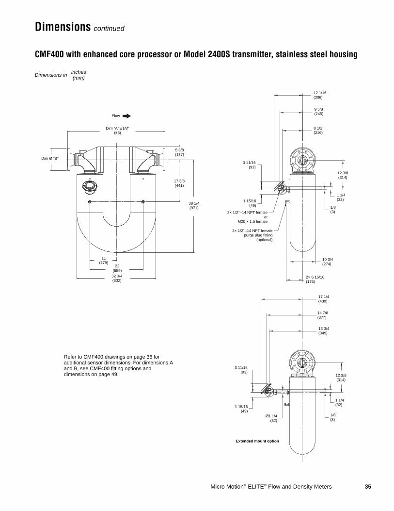
Dimensions continued
CMF400 with enhanced core processor or Model 2400S transmitter, stainless steel housing
Dimensions in inches(mm)
Refer to CMF400 drawings on page 36 for additional sensor dimensions. For dimensions A and B, see CMF400 fitting options and dimensions on page 49.
Dim Ø “B”
1 15/16(49)
2× 1/2″–14 NPT femaleor
M20 × 1.5 female
2× 1/2″–14 NPT femalepurge plug fitting
(optional)
5 3/8(137)
Dim “A” ±1/8″(±3)
17 3/8(441)
38 1/4(971)
11(279)
22(559)
32 3/4(832)
3 11/16(93)
8 1/2(216)
9 5/8(245)
12 1/16(306)
12 3/8(314)
1 1/4(32)
10 3/4(274)
2× 6 15/16(175)
17 1/4(439)
Ø1 1/4(32)
12 3/8(314)
1 1/4(32)
3 11/16(93)
1 15/16(49)
Extended mount option
14 7/8(377)
13 3/4(349)
Flow
1/8(3)
1/8(3)

36 Micro Motion® ELITE® Flow and Density Meters
Dimensions continued
CMF400 with core processor
CMF400 with junction box
5 3/8(137)
10 3/4(274)
9 1/8(231) 7 3/8
(188)
Ø1 1/4(32)
Extended mount option
14 1/2(368)Dim. A*
±3/16 (±5)
15 (380)
12 13/16(325)
38 1/4 (971)
Dimensions in inches(mm)
32 3/4(832)
Dim. Ø B*
22(559)
11(279)
17 3/8(441)
Flow
5 3/8(137)
38 1/4(971)
32 3/4(832)
Dim. A ±3/16*(±5)
10 3/4(274)
7 11/16(195)
6 3/8(162)
13 1/16(332)
11 3/4(298)
Ø1 1/4(32)
Dim. Ø B*
Extended mount option
*For dimensions A and B, see page 49.
Dimensions in inches(mm)
14 5/16(363)17 3/8
(441)
22(559)
11(279)
Flow
Micro Motion® ELITE® Flow and Density Meters 37
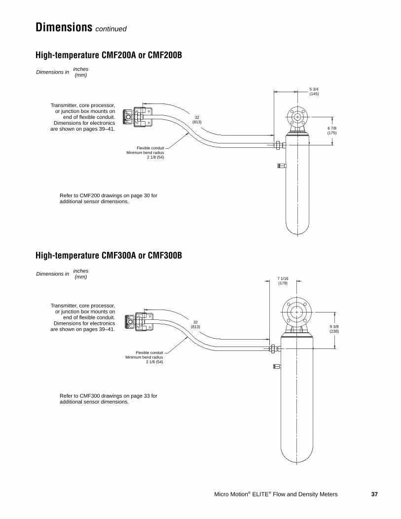
Dimensions continued
High-temperature CMF200A or CMF200B
High-temperature CMF300A or CMF300B
Dimensions in inches(mm)
Refer to CMF200 drawings on page 30 for additional sensor dimensions.
Transmitter, core processor,or junction box mounts on
end of flexible conduit.Dimensions for electronics
are shown on pages 39–41.
32(813)
Flexible conduitMinimum bend radius
2 1/8 (54)
6 7/8(175)
5 3/4(145)
Dimensions in inches(mm)
Refer to CMF300 drawings on page 33 for additional sensor dimensions.
Transmitter, core processor,or junction box mounts on
end of flexible conduit.Dimensions for electronics
are shown on pages 39–41.32
(813)
Flexible conduitMinimum bend radius
2 1/8 (54)
9 3/8(238)
7 1/16(179)
38 Micro Motion® ELITE® Flow and Density Meters
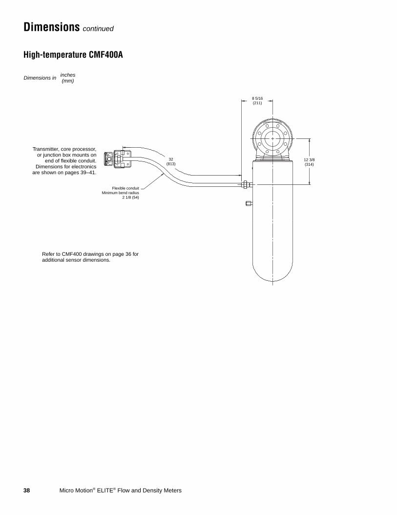
Dimensions continued
High-temperature CMF400A
Dimensions in inches(mm)
Refer to CMF400 drawings on page 36 for additional sensor dimensions.
Transmitter, core processor,or junction box mounts on
end of flexible conduit.Dimensions for electronics
are shown on pages 39–41.
32(813)
Flexible conduitMinimum bend radius
2 1/8 (54)
12 3/8(314)
8 5/16(211)
Micro Motion® ELITE® Flow and Density Meters 39
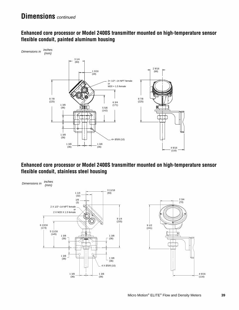
Dimensions continued
Enhanced core processor or Model 2400S transmitter mounted on high-temperature sensor flexible conduit, painted aluminum housing
Enhanced core processor or Model 2400S transmitter mounted on high-temperature sensor flexible conduit, stainless steel housing
Dimensions in inches(mm)
2 9/16(66)
8 7/8(225)
4 9/16(116)
8 7/8(225)
1 3/8(36)
1 3/8(36)
1 3/8(36)
4× Ø3/8 (10)
5 5/8(142)
6 3/4(171)
3 1/4(83)
1 3/16(29)
2× 1/2″–14 NPT femaleorM20 × 1.5 female
1 3/8(36)
3 11/16(93)1 1/4
(32)
1/8(3)
2 X 1/2″–14 NPT femaleor
2 X M20 X 1.5 female
6 13/16(173)
5 11/16(145)
1 3/8(36)
1 3/8(36)
1 3/8(36)
1 3/8(36)
4 X Ø3/8 (10)
1 3/8(36)
1 3/8(36)
9 1/4(235)
9 1/2(241)
2 3/4(70)
4 9/16(116)
Dimensions in inches(mm)
40 Micro Motion® ELITE® Flow and Density Meters
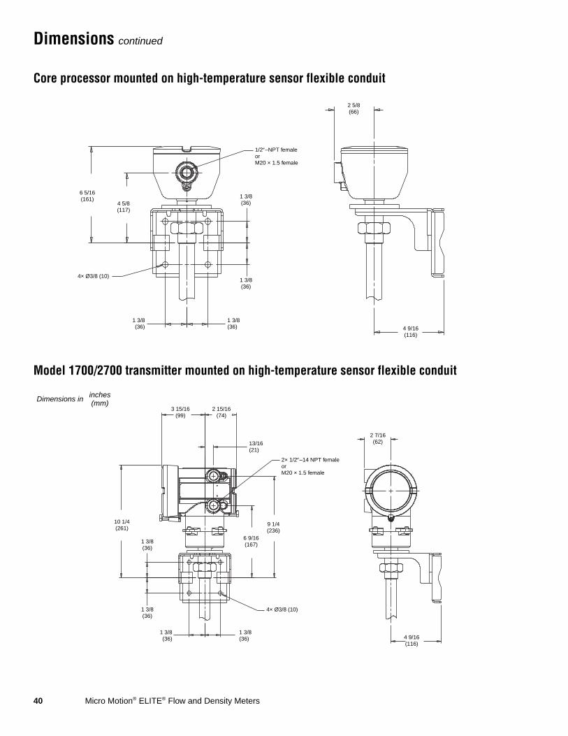
Dimensions continued
Core processor mounted on high-temperature sensor flexible conduit
Model 1700/2700 transmitter mounted on high-temperature sensor flexible conduit
2 5/8(66)
4 9/16(116)
1/2″–NPT femaleorM20 × 1.5 female
4 5/8(117)
6 5/16(161)
4× Ø3/8 (10)1 3/8(36)
1 3/8(36)
1 3/8(36)
1 3/8(36)
2 7/16(62)
4 9/16(116)
10 1/4(261)
3 15/16(99)
1 3/8(36)
1 3/8(36)
1 3/8(36)
2 15/16(74)
13/16(21)
2× 1/2″–14 NPT femaleorM20 × 1.5 female
6 9/16(167)
9 1/4(236)
4× Ø3/8 (10)
1 3/8(36)
Dimensions in inches(mm)
Micro Motion® ELITE® Flow and Density Meters 41
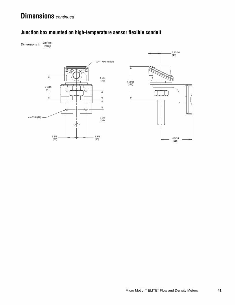
Dimensions continued
Junction box mounted on high-temperature sensor flexible conduit
1 15/16(49)
4 9/16(116)
3/4″–NPT female
3 9/16(91)
4× Ø3/8 (10)
1 3/8(36)
1 3/8(36)
4 15/16(125)
1 3/8(36)
1 3/8(36)
Dimensions in inches(mm)

42 Micro Motion® ELITE® Flow and Density Meters
Fitting options
Fitting code
Dim. A face-to-faceinches (mm)
Dim. B outside diameterinches (mm)
CMF010 fitting options(1)
(1) Fittings listed here are standard options. Other types of fittings are available. The face to face dimensions for any custom fittings ordered using a 998 or 999 fitting code are not represented in this table. It is necessary to confirm face to face dimensions of these fittings at time of ordering. Contact your local Micro Motion representative.
316L stainless steel sensors
1/2-inch ANSI CL150 weld neck raised face flange 313 7 7/8 (199) 3 1/2 (89)
1/2-inch ANSI CL300 weld neck raised face flange 314 8 3/16 (209) 3 3/4 (95)
1/2-inch ANSI CL600 weld neck raised face flange 315 8 11/16 (221) 3 3/4 (95)
1/2-inch sanitary fitting (Tri-Clamp compatible) 321 6 15/16 (177) 1 (25)
DN15 PN40 weld neck flange; DIN 2635 type C face 300 7 7/16 (189) 3 3/4 (95)
DN15 PN40 weld neck flange; EN 1092-1 Form B1 176 7 7/16 (189) 3 3/4 (95)
DN15 PN40 weld neck flange; EN 1092-1 Form D 310 7 7/16 (189) 3 3/4 (95)
DN15 PN100 weld neck flange; DIN 2637 type E face 302 8 (203) 4 1/8 (105)
DN15 PN100 weld neck flange; EN 1092-1 Form B2 177 8 (203) 4 1/8 (105)
DN15 PN100 weld neck flange; EN 1092-1 Form D 178 8 (203) 4 1/8 (105)
DN25 PN40 Weld Neck Flange; EN 1092-1 Form B1 172 7 9/16 (193) 4 1/2 (115)
DN25 PN40 Weld Neck Flange; EN 1092-1 Form D 183 7 9/16 (193) 4 1/2 (115)
JIS 15mm 10K weld neck raised face flange 304 7 3/16 (183) 3 3/4 (95)
JIS 15mm 20K weld neck raised face flange 305 7 3/16 (183) 3 3/4 (95)
1/4-inch NPT female Swagelok size 4 VCO fitting 323 6 7/16 (164) —
1/4-inch tube compression fitting 324 6 7/16 (164) —
6 mm tube compression fitting 325 6 7/16 (164) —
304L stainless steel sensors
1/2-inch ANSI CL150 weld neck raised face flange 413 7 7/8 (199) 3 1/2 (89)
1/2-inch ANSI CL300 weld neck raised face flange 414 8 3/16 (209) 3 3/4 (95)
DN15 PN40 weld neck flange; DIN 2526 type C face 423 7 7/16 (189) 3 3/4 (95)
DN15 PN40 weld neck flange; EN 1092-1 Form B1 421 7 7/16 (189) 3 3/4 (95)
Nickel alloy sensors
1/2-inch ANSI CL150 lap joint flange 520 7 7/8 (199) 3 1/2 (89)
1/2-inch ANSI CL300 lap joint flange 521 8 3/16 (209) 3 3/4 (95)
DN15 PN40 lap joint flange; DIN 2656 type C face 523 9 7/16 (240) 3 3/4 (95)
DN15 PN40 lap joint flange; EN 1092-1 Form B1 524 9 7/16 (240) 3 3/4 (95)
JIS 15mm 10K lap joint flange 522 8 3/16 (208) 3 3/4 (95)
1/4-inch NPT female Swagelok size 4 VCO fitting 323 6 7/16 (164) —
High-pressure CMF010P fitting options(1)
1/4-inch NPT female Swagelok size 4 VCO fitting 323 6 7/16 (164) —
1/4-inch tube compression fitting 324 6 7/16 (164) —
6 mm tube compression fitting 325 6 7/16 (164) —

Micro Motion® ELITE® Flow and Density Meters 43
Fitting options continued
Fitting code
Dim. A face-to-faceinches (mm)
Dim. B outside diameterinches (mm)
CMF025 fitting options(1)
(1) Fittings listed here are standard options. Other types of fittings are available. The face to face dimensions for any custom fittings ordered using a 998 or 999 fitting code are not represented in this table. It is necessary to confirm face to face dimensions of these fittings at time of ordering. Contact your local Micro Motion representative.
316L stainless steel sensors
Wafer style; 1/2-inch ANSI (150 lb; 300 lb; 600 lb bolt kit) 009 2 3/8 (60) 1 13/16 (46)
Wafer style, 15mm DIN 2526; type C face (PN40 bolt kit) 016 2 3/8 (60) 1 13/16 (46)
Wafer style; 15mm DIN 2512; type N grooved face (PN40 bolt kit) 017 2 3/8 (60) 1 13/16 (46)
Wafer style; 15mm DIN 2526; type E face (PN100 bolt kit) 018 2 3/8 (60) 1 13/16 (46)
Wafer style; 15mm DIN 2512; type N grooved face (PN100 bolt kit) 019 2 3/8 (60) 1 13/16 (46)
Wafer style; 15mm; standard JIS facing (10K; 20K bolt kit) 029 2 3/8 (60) 1 13/16 (46)
1/2-inch ANSI CL150 weld neck raised face flange 313 6 3/4 (172) 3 1/2 (89)
1/2-inch ANSI CL300 weld neck raised face flange 314 7 1/8 (181) 3 3/4 (95)
1/2-inch ANSI CL600 weld neck raised face flange 315 7 5/8 (194) 3 3/4 (95)
1/2-inch NPT female Swagelok size 8 VCO fitting 319 4 11/16 (119) —
1/2-inch sanitary fitting (Tri-Clamp compatible) 321 4 11/16 (119) 1 (25)
DN15 PN40 weld neck flange; DIN 2635 type C face 300 6 5/16 (160) 3 3/4 (95)
DN15 PN40 weld neck flange; EN 1092-1 Form B1 176 6 5/16 (160) 3 3/4 (95)
DN15 PN40 weld neck flange; DIN 2635 type N grooved face 301 6 5/16 (160) 3 3/4 (95)
DN15 PN40 weld neck flange; EN 1092-1 Form D 310 6 5/16 (160) 3 3/4 (95)
DN15 PN100 weld neck flange; DIN 2637 type E face 302 6 15/16 (176) 4 1/8 (105)
DN15 PN100 weld neck flange; EN 1092-1 Form B2 177 6 15/16 (176) 4 1/8 (105)
DN15 PN100 weld neck flange; DIN 2637 type N grooved face 303 6 15/16 (176) 4 1/8 (105)
DN15 PN100 weld neck flange; EN 1092-1 Form D 178 6 15/16 (176) 4 1/8 (105)
DN25 PN40 Weld Neck Flange; EN 1092-1 Form B1 172 6 7/16 (164) 4 1/2 (115)
DN25 PN40 Weld Neck Flange; EN 1092-1 Form D 183 6 7/16 (164) 4 1/2 (115)
JIS 15mm 10K weld neck raised face flange 304 6 1/8 (156) 3 3/4 (95)
JIS 15mm 20K weld neck raised face flange 305 6 1/8 (156) 3 3/4 (95)
304L stainless steel sensors
1/2-inch ANSI CL150 weld neck raised face flange 413 6 3/4 (172) 3 1/2 (89)
1/2-inch ANSI CL300 weld neck raised face flange 414 7 1/8 (181) 3 3/4 (95)
DN15 PN40 weld neck flange; DIN 2526 type C face 423 6 5/16 (160) 3 3/4 (95)
DN15 PN40 weld neck flange; EN 1092-1 Form B1 421 6 5/16 (160) 3 3/4 (95)
Nickel alloy sensors
1/2-inch ANSI CL150 lap joint flange 520 6 3/4 (172) 3 1/2 (89)
1/2-inch ANSI CL300 lap joint flange 521 7 1/8 (181) 3 3/4 (95)
DN15 PN40 lap joint flange; DIN 2656 type C face 523 7 5/16 (186) 3 3/4 (95)
DN15 PN40 lap joint flange; EN 1092-1 Form B1 524 7 5/16 (186) 3 3/4 (95)
JIS 15mm 10K lap joint flange 522 7 1/8 (181) 3 3/4 (95)
44 Micro Motion® ELITE® Flow and Density Meters
Fitting options continued
Fitting code
Dim. A face-to-faceinches (mm)
Dim. B outside diameterinches (mm)
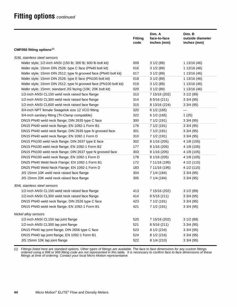
CMF050 fitting options(1)
(1) Fittings listed here are standard options. Other types of fittings are available. The face to face dimensions for any custom fittings ordered using a 998 or 999 fitting code are not represented in this table. It is necessary to confirm face to face dimensions of these fittings at time of ordering. Contact your local Micro Motion representative.
316L stainless steel sensors
Wafer style; 1/2-inch ANSI (150 lb; 300 lb; 600 lb bolt kit) 009 3 1/2 (89) 1 13/16 (46)
Wafer style; 15mm DIN 2526; type C face (PN40 bolt kit) 016 3 1/2 (89) 1 13/16 (46)
Wafer style; 15mm DIN 2512; type N grooved face (PN40 bolt kit) 017 3 1/2 (89) 1 13/16 (46)
Wafer style; 15mm DIN 2526; type E face (PN100 bolt kit) 018 3 1/2 (89) 1 13/16 (46)
Wafer style; 15mm DIN 2512; type N grooved face (PN100 bolt kit) 019 3 1/2 (89) 1 13/16 (46)
Wafer style; 15mm; standard JIS facing (10K; 20K bolt kit) 029 3 1/2 (89) 1 13/16 (46)
1/2-inch ANSI CL150 weld neck raised face flange 313 7 15/16 (202) 3 1/2 (89)
1/2-inch ANSI CL300 weld neck raised face flange 314 8 5/16 (211) 3 3/4 (95)
1/2-inch ANSI CL600 weld neck raised face flange 315 8 13/16 (224) 3 3/4 (95)
3/4-inch NPT female Swagelok size 12 VCO fitting 320 6 1/2 (165) —
3/4-inch sanitary fitting (Tri-Clamp compatible) 322 6 1/2 (165) 1 (25)
DN15 PN40 weld neck flange; DIN 2635 type C face 300 7 1/2 (191) 3 3/4 (95)
DN15 PN40 weld neck flange; EN 1092-1 Form B1 176 7 1/2 (191) 3 3/4 (95)
DN15 PN40 weld neck flange; DIN 2635 type N grooved face 301 7 1/2 (191) 3 3/4 (95)
DN15 PN40 weld neck flange; EN 1092-1 Form D 310 7 1/2 (191) 3 3/4 (95)
DN15 PN100 weld neck flange; DIN 2637 type E face 302 8 1/16 (205) 4 1/8 (105)
DN15 PN100 weld neck flange; EN 1092-1 Form B2 177 8 1/16 (205) 4 1/8 (105)
DN15 PN100 weld neck flange; DIN 2637 type N grooved face 303 8 1/16 (205) 4 1/8 (105)
DN15 PN100 weld neck flange; EN 1092-1 Form D 178 8 1/16 (205) 4 1/8 (105)
DN25 PN40 Weld Neck Flange; EN 1092-1 Form B1 172 7 11/16 (195) 4 1/2 (115)
DN25 PN40 Weld Neck Flange; EN 1092-1 Form D 183 7 11/16 (195) 4 1/2 (115)
JIS 15mm 10K weld neck raised face flange 304 7 1/4 (184) 3 3/4 (95)
JIS 15mm 20K weld neck raised face flange 305 7 1/4 (184) 3 3/4 (95)
304L stainless steel sensors
1/2-inch ANSI CL150 weld neck raised face flange 413 7 15/16 (202) 3 1/2 (89)
1/2-inch ANSI CL300 weld neck raised face flange 414 8 5/16 (211) 3 3/4 (95)
DN15 PN40 weld neck flange; DIN 2526 type C face 423 7 1/2 (191) 3 3/4 (95)
DN15 PN40 weld neck flange; EN 1092-1 Form B1 421 7 1/2 (191) 3 3/4 (95)
Nickel alloy sensors
1/2-inch ANSI CL150 lap joint flange 520 7 15/16 (202) 3 1/2 (89)
1/2-inch ANSI CL300 lap joint flange 521 8 5/16 (211) 3 3/4 (95)
DN15 PN40 lap joint flange; DIN 2656 type C face 523 8 1/2 (216) 3 3/4 (95)
DN15 PN40 lap joint flange; EN 1092-1 Form B1 524 8 1/2 (216) 3 3/4 (95)
JIS 15mm 10K lap joint flange 522 8 1/4 (210) 3 3/4 (95)
Micro Motion® ELITE® Flow and Density Meters 45
Fitting options continued
Fitting code
Dim. A face-to-faceinches (mm)
Dim. B outside diameterinches (mm)
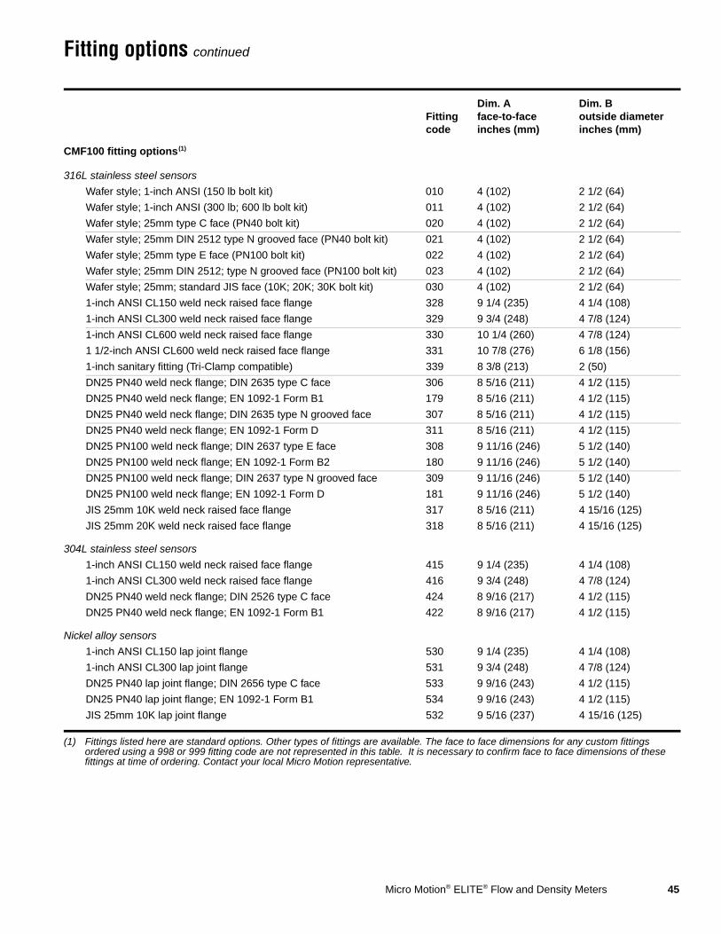
CMF100 fitting options(1)
(1) Fittings listed here are standard options. Other types of fittings are available. The face to face dimensions for any custom fittings ordered using a 998 or 999 fitting code are not represented in this table. It is necessary to confirm face to face dimensions of these fittings at time of ordering. Contact your local Micro Motion representative.
316L stainless steel sensors
Wafer style; 1-inch ANSI (150 lb bolt kit) 010 4 (102) 2 1/2 (64)
Wafer style; 1-inch ANSI (300 lb; 600 lb bolt kit) 011 4 (102) 2 1/2 (64)
Wafer style; 25mm type C face (PN40 bolt kit) 020 4 (102) 2 1/2 (64)
Wafer style; 25mm DIN 2512 type N grooved face (PN40 bolt kit) 021 4 (102) 2 1/2 (64)
Wafer style; 25mm type E face (PN100 bolt kit) 022 4 (102) 2 1/2 (64)
Wafer style; 25mm DIN 2512; type N grooved face (PN100 bolt kit) 023 4 (102) 2 1/2 (64)
Wafer style; 25mm; standard JIS face (10K; 20K; 30K bolt kit) 030 4 (102) 2 1/2 (64)
1-inch ANSI CL150 weld neck raised face flange 328 9 1/4 (235) 4 1/4 (108)
1-inch ANSI CL300 weld neck raised face flange 329 9 3/4 (248) 4 7/8 (124)
1-inch ANSI CL600 weld neck raised face flange 330 10 1/4 (260) 4 7/8 (124)
1 1/2-inch ANSI CL600 weld neck raised face flange 331 10 7/8 (276) 6 1/8 (156)
1-inch sanitary fitting (Tri-Clamp compatible) 339 8 3/8 (213) 2 (50)
DN25 PN40 weld neck flange; DIN 2635 type C face 306 8 5/16 (211) 4 1/2 (115)
DN25 PN40 weld neck flange; EN 1092-1 Form B1 179 8 5/16 (211) 4 1/2 (115)
DN25 PN40 weld neck flange; DIN 2635 type N grooved face 307 8 5/16 (211) 4 1/2 (115)
DN25 PN40 weld neck flange; EN 1092-1 Form D 311 8 5/16 (211) 4 1/2 (115)
DN25 PN100 weld neck flange; DIN 2637 type E face 308 9 11/16 (246) 5 1/2 (140)
DN25 PN100 weld neck flange; EN 1092-1 Form B2 180 9 11/16 (246) 5 1/2 (140)
DN25 PN100 weld neck flange; DIN 2637 type N grooved face 309 9 11/16 (246) 5 1/2 (140)
DN25 PN100 weld neck flange; EN 1092-1 Form D 181 9 11/16 (246) 5 1/2 (140)
JIS 25mm 10K weld neck raised face flange 317 8 5/16 (211) 4 15/16 (125)
JIS 25mm 20K weld neck raised face flange 318 8 5/16 (211) 4 15/16 (125)
304L stainless steel sensors
1-inch ANSI CL150 weld neck raised face flange 415 9 1/4 (235) 4 1/4 (108)
1-inch ANSI CL300 weld neck raised face flange 416 9 3/4 (248) 4 7/8 (124)
DN25 PN40 weld neck flange; DIN 2526 type C face 424 8 9/16 (217) 4 1/2 (115)
DN25 PN40 weld neck flange; EN 1092-1 Form B1 422 8 9/16 (217) 4 1/2 (115)
Nickel alloy sensors
1-inch ANSI CL150 lap joint flange 530 9 1/4 (235) 4 1/4 (108)
1-inch ANSI CL300 lap joint flange 531 9 3/4 (248) 4 7/8 (124)
DN25 PN40 lap joint flange; DIN 2656 type C face 533 9 9/16 (243) 4 1/2 (115)
DN25 PN40 lap joint flange; EN 1092-1 Form B1 534 9 9/16 (243) 4 1/2 (115)
JIS 25mm 10K lap joint flange 532 9 5/16 (237) 4 15/16 (125)

46 Micro Motion® ELITE® Flow and Density Meters
Fitting options continued
Fitting code
Dim. A face-to-faceinches (mm)
Dim. B outside diameterinches (mm)
CMF200 fitting options(1)
(1) Fittings listed here are standard options. Other types of fittings are available. The face to face dimensions for any custom fittings ordered using a 998 or 999 fitting code are not represented in this table. It is necessary to confirm face to face dimensions of these fittings at time of ordering. Contact your local Micro Motion representative.
316L stainless steel sensors
1 1/2-inch ANSI CL150 weld neck raised face flange 341 22 7/8 (581) 5 (127)
1 1/2-inch ANSI CL300 weld neck raised face flange 342 23 3/8 (594) 6 1/8 (156)
1 1/2-inch ANSI CL600 weld neck raised face flange 343 23 7/8 (606) 6 1/8 (156)
2-inch ANSI CL150 weld neck raised face flange 418 22 7/8 (581) 6 (152)
2-inch ANSI CL300 weld neck raised face flange 419 23 3/8 (594) 6 1/2 (165)
2-inch ANSI CL600 weld neck raised face flange 420 23 5/8 (600) 6 1/2 (165)
1 1/2-inch sanitary fitting (Tri-Clamp compatible)(2)
(2) Not available with high-temperature models CMF200A or CMF200B.
351 21 3/8 (543) 2 (51)
2-inch sanitary fitting (Tri-Clamp compatible)(2) 352 21 3/8 (543) 2 1/2 (64)
DN40 PN40 weld neck flange; DIN 2635 type C face 381 21 11/16 (551) 5 15/16 (150)
DN40 PN40 weld neck flange; EN 1092-1 Form B1 368 21 9/16 (547) 5 15/16 (150)
DN40 PN40 weld neck flange; DIN 2635 type N grooved face 383 21 11/16 (551) 5 15/16 (150)
DN40 PN40 weld neck flange; EN 1092-1 Form D 312 21 9/16 (547) 5 15/16 (150)
DN40 PN100 weld neck flange; DIN 2637 type E face 377 23 1/8 (587) 6 11/16 (170)
DN40 PN100 weld neck flange; EN 1092-1 Form B2 363 22 7/8 (580) 6 11/16 (170)
DN40 PN100 weld neck flange; DIN 2637 type N grooved face 379 23 1/8 (587) 6 11/16 (170)
DN40 PN100 weld neck flange; EN 1092-1 Form D 366 22 7/8 (580) 6 11/16 (170)
DN50 PN40 weld neck flange; DIN 2635 type C face 382 21 15/16 (557) 6 1/2 (165)
DN50 PN40 weld neck flange; EN 1092-1 Form B1 369 21 3/4 (553) 6 1/2 (165)
DN50 PN40 weld neck flange; DIN 2635 type N grooved face 384 21 15/16 (557) 6 1/2 (165)
DN50 PN40 weld neck flange; EN 1092-1 Form D 316 21 3/4 (553) 6 1/2 (165)
DN50 PN100 weld neck flange; DIN 2637 type E face 378 23 9/16 (598) 7 11/16 (195)
DN50 PN100 weld neck flange; EN 1092-1 Form B2 365 23 5/16 (593) 7 11/16 (195)
DN50 PN100 weld neck flange; DIN 2637 type N grooved face 380 23 9/16 (598) 7 11/16 (195)
DN50 PN100 weld neck flange; EN 1092-1 Form D 367 23 5/16 (593) 7 11/16 (195)
JIS 40mm 10K weld neck raised face flange 385 21 9/16 (548) 5 1/2 (140)
JIS 40mm 20K weld neck raised face flange 387 21 9/16 (548) 5 1/2 (140)
JIS 50mm 10K weld neck raised face flange 386 21 13/16 (554) 6 1/8 (156)
JIS 50mm 20K weld neck raised face flange 388 21 13/16 (554) 6 1/8 (156)

Micro Motion® ELITE® Flow and Density Meters 47
Fitting options continued
Fitting code
Dim. A face-to-faceinches (mm)
Dim. B outside diameterinches (mm)
CMF200 fitting options(1)
(1) Fittings listed here are standard options. Other types of fittings are available. The face to face dimensions for any custom fittings ordered using a 998 or 999 fitting code are not represented in this table. It is necessary to confirm face to face dimensions of these fittings at time of ordering. Contact your local Micro Motion representative.
304L stainless steel sensors
1 1/2-inch ANSI CL150 weld neck raised face flange 441 22 7/8 (581) 5 (127)
1 1/2-inch ANSI CL300 weld neck raised face flange 442 23 3/8 (594) 6 1/8 (156)
2-inch ANSI CL150 weld neck raised face flange 518 22 7/8 (581) 6 (152)
2-inch ANSI CL300 weld neck raised face flange 519 23 1/2 (597) 6 1/2 (165)
DN40 PN40 weld neck flange; DIN 2526 type C face 481 21 11/16 (551) 5 15/16 (150)
DN40 PN40 weld neck flange; EN 1092-1 Form B1 457 21 9/16 (547) 5 15/16 (150)
DN50 PN40 weld neck raised face flange; DIN 2526 type C face 482 21 15/16 (557) 6 1/2 (165)
DN50 PN40 weld neck raised face flange; EN 1092-1 Form B1 458 21 3/4 (553) 6 1/2 (165)
Nickel alloy sensors
1 1/2-inch ANSI CL150 lap joint flange 540 22 7/8 (581) 5 (127)
1 1/2-inch ANSI CL300 lap joint flange 541 23 3/8 (594) 6 1/8 (156)
2-inch ANSI CL150 lap joint flange 544 22 7/8 (581) 6 (152)
2-inch ANSI CL300 lap joint flange 545 23 3/8 (594) 6 1/2 (165)
DN40 PN40 lap joint flange; DIN 2656 type C face 543 21 11/16 (551) 5 15/16 (150)
DN40 PN40 lap joint flange; EN 1092-1 Form B1 548 21 11/16 (551) 5 15/16 (150)
DN50 PN40 lap joint flange; DIN 2656 type C face 547 21 15/16 (557) 6 1/2 (165)
DN50 PN40 lap joint flange; EN 1092-1 Form B1 549 21 15/16 (557) 6 1/2 (165)
JIS 40mm 10K lap joint flange 542 21 9/16 (548) 5 1/2 (140)
JIS 50mm 10K lap joint flange 546 21 13/16 (554) 6 1/8 (155)

48 Micro Motion® ELITE® Flow and Density Meters
Fitting options continued
Fitting code
Dim. A face-to-faceinches (mm)
Dim. B outside diameterinches (mm)
CMF300 fitting options(1)
(1) Fittings listed here are standard options. Other types of fittings are available. The face to face dimensions for any custom fittings ordered using a 998 or 999 fitting code are not represented in this table. It is necessary to confirm face to face dimensions of these fittings at time of ordering. Contact your local Micro Motion representative.
316L stainless steel sensors3-inch ANSI CL150 weld neck raised face flange 355 33 11/16 (856) 7 1/2 (191)3-inch ANSI CL300 weld neck raised face flange 356 34 7/16 (875) 8 1/4 (210)3-inch ANSI CL600 weld neck raised face flange 357 35 3/16 (894) 8 1/4 (210)4-inch ANSI CL150 weld neck raised face flange 425 34 1/16 (865) 9 (229)4-inch ANSI CL300 weld neck raised face flange 426 35 (889) 10 (254)4-inch ANSI CL600 weld neck raised face flange 427 36 11/16 (932) 10 3/4 (273)3-inch sanitary fitting (Tri-Clamp compatible)(2)
(2) Not available with high-temperature models CMF300A or CMF300B.
361 32 (813) 3 9/16 (90)DN80 PN40 weld neck flange; DIN 2635 type C face 391 32 7/8 (835) 7 7/8 (200)DN80 PN40 weld neck flange; EN 1092-1 Form B1 371 32 3/4 (832) 7 7/8 (200)DN80 PN40 weld neck flange; DIN 2635 type N grooved face 393 32 7/8 (835) 7 7/8 (200)DN80 PN40 weld neck flange; EN 1092-1 Form D 326 32 3/4 (832) 7 7/8 (200)DN80 PN100 weld neck flange; DIN 2637 type E face 395 34 9/16 (878) 9 1/16 (230)DN80 PN100 weld neck flange; EN 1092-1 Form B2 373 34 5/16 (872) 9 1/16 (230)DN80 PN100 weld neck flange; DIN 2637 type N grooved face 397 34 9/16 (878) 9 1/16 (230)DN80 PN100 weld neck flange; EN 1092-1 Form D 375 34 5/16 (872) 9 1/16 (230)DN100 PN40 weld neck flange; DIN 2635 type C face 392 33 1/4 (845) 9 1/4 (235)DN100 PN40 weld neck flange; EN 1092-1 Form B1 372 33 1/4 (845) 9 1/4 (235)DN100 PN40 weld neck flange; DIN 2635 type N grooved face 394 33 1/4 (845) 9 1/4 (235)DN100 PN40 weld neck flange; EN 1092-1 Form D 333 33 1/4 (845) 9 1/4 (235)DN100 PN100 weld neck flange; DIN 2637 type E face 396 35 9/16 (903) 10 7/16 (265)DN100 PN100 weld neck flange; EN 1092-1 Form B2 374 35 1/4 (896) 10 7/16 (265)DN100 PN100 weld neck flange; DIN 2637 type N grooved face 398 35 9/16 (903) 10 7/16 (265)DN100 PN100 weld neck flange; EN 1092-1 Form D 359 35 1/4 (896) 10 7/16 (265)JIS 80mm 10K weld neck raised face flange 400 33 3/8 (848) 7 5/16 (186)JIS 80mm 20K weld neck raised face flange 402 33 3/8 (848) 7 7/8 (200)JIS 100mm 10K weld neck raised face flange 401 33 9/16 (853) 8 1/4 (210)JIS 100mm 20K weld neck raised face flange 403 33 9/16 (853) 8 7/8 (225)
304L stainless steel sensors3-inch ANSI CL150 weld neck raised face flange 455 33 11/16 (856) 7 1/2 (191)3-inch ANSI CL300 weld neck raised face flange 456 34 7/16 (875) 8 1/4 (210)DN80 PN40 weld neck flange; DIN 2526 type C face 491 32 7/8 (835) 7 7/8 (200)DN80 PN40 weld neck flange; EN 1092-1 Form B1 459 32 3/4 (832) 7 7/8 (200)
Nickel alloy sensors3-inch ANSI CL150 lap joint flange 550 33 11/16 (856) 7 1/2 (191)3-inch ANSI CL300 lap joint flange 551 34 7/16 (875) 8 1/4 (210)DN80 PN40 lap joint flange; DIN 2656 type C face 553 32 7/8 (835) 7 7/8 (200)DN80 PN40 lap joint flange; EN 1092-1 Form B1 554 32 7/8 (835) 7 7/8 (200)JIS 80mm 10K lap joint flange 552 33 3/8 (848) 7 5/16 (185)

Micro Motion® ELITE® Flow and Density Meters 49
Fitting options continued
Fitting code
Dim. A face-to-faceinches (mm)
Dim. B outside diameterinches (mm)
CMF400 fitting options(1)
(1) Fittings listed here are standard options. Other types of fittings are available. The face to face dimensions for any custom fittings ordered using a 998 or 999 fitting code are not represented in this table. It is necessary to confirm face to face dimensions of these fittings at time of ordering. Contact your local Micro Motion representative.
316L stainless steel sensors
4-inch ANSI CL150 weld neck raised face flange 435 40 3/16 (1021) 9 (229)
4-inch ANSI CL300 weld neck raised face flange 436 41 (1041) 10 (254)
4-inch ANSI CL600 weld neck raised face flange 437 42 11/16 (1084) 10 3/4 (273)
4-inch ANSI CL900 weld neck raised face flange(2)
(2) Available only with high-temperature model CMF400A.
438 43 11/16 (1110) 11 1/2 (292)
6-inch ANSI CL150 weld neck raised face flange 451 40 5/16 (1024) 11 (279)
6-inch ANSI CL300 weld neck raised face flange 452 41 5/16 (1049) 12 1/2 (318)
6-inch ANSI CL600 weld neck raised face flange 453 43 1/2 (1105) 14 (356)
DN100 PN40 weld neck flange; DIN 2635 type C face 460 39 5/16 (999) 9 1/4 (235)
DN100 PN40 weld neck flange; EN 1092-1 Form B1 443 39 5/16 (999) 9 1/4 (235)
DN100 PN40 weld neck flange; DIN 2635 type N grooved face 462 39 5/16 (999) 9 1/4 (235)
DN100 PN40 weld neck flange; EN 1092-1 Form D 480 39 5/16 (999) 9 1/4 (235)
DN100 PN100 weld neck flange; DIN 2637 type E face 464 41 5/16 (1049) 10 7/16 (265)
DN100 PN100 weld neck flange; EN 1092-1 Form B2 445 41 5/16 (1049) 10 7/16 (265)
DN100 PN100 weld neck flange; DIN 2637 type N grooved face 466 41 5/16 (1049) 10 7/16 (265)
DN100 PN100 weld neck flange; EN 1092-1 Form D 447 41 5/16 (1049) 10 7/16 (265)
DN150 PN40 weld neck flange; DIN 2635 type C face 461 39 5/8 (1006) 11 13/16 (300)
DN150 PN40 weld neck flange; EN 1092-1 Form B1 444 40 1/16 (1018) 11 13/16 (300)
DN150 PN40 weld neck flange; DIN 2635 type N grooved face 463 39 5/8 (1006) 11 13/16 (300)
DN150 PN40 weld neck flange; EN 1092-1 Form D 478 40 1/16 (1018) 11 13/16 (300)
DN150 PN100 weld neck flange; DIN 2637 type E face 465 41 15/16 (1065) 14 (355)
DN150 PN100 weld neck flange; EN 1092-1 Form B2 446 43 1/4 (1099) 14 (355)
DN150 PN100 weld neck flange; DIN 2637 type N grooved face 467 41 15/16 (1065) 14 (355)
DN150 PN100 weld neck flange; EN 1092-1 Form D 448 43 1/4 (1099) 14 (355)
JIS 100mm 10K weld neck raised face flange 470 39 5/16 (999) 8 1/4 (210)
JIS 100mm 20K weld neck raised face flange 472 39 13/16 (1011) 8 7/8 (225)
JIS 150mm 10K weld neck raised face flange 471 39 5/8 (1006) 11 (280)
JIS 150mm 20K weld neck raised face flange 473 40 1/8 (1018) 12 (305)

50 Micro Motion® ELITE® Flow and Density Meters
Fitting options continued
Fitting code
Dim. A face-to-faceinches (mm)
Dim. B outside diameterinches (mm)
CMF400 fitting options(1)
(1) Fittings listed here are standard options. Other types of fittings are available. The face to face dimensions for any custom fittings ordered using a 998 or 999 fitting code are not represented in this table. It is necessary to confirm face to face dimensions of these fittings at time of ordering. Contact your local Micro Motion representative.
Nickel alloy sensors
4-inch ANSI CL150 lap joint 907 42 7/16 (1078) 9 (229)
DN100 PN40 weld neck flange; EN 1092-1 Form B1 906 39 5/16 (999) 9 1/4 (235)
DN100 PN100 weld neck flange; EN 1092-1 Form B2 908 41 1/4 (1048) 10 7/16 (265)
DN100 PN160 weld neck flange; EN 1092-1 Form B2 910 42 1/16 (1068) 10 7/16 (265)
4-inch ANSI CL150 weld neck raised face flange 911 40 3/16 (1021) 9 (229)
4-inch ANSI CL300 weld neck raised face flange 912 40 15/16 (1024) 10 (254)
4-inch ANSI CL600 weld neck raised face flange 913 42 11/16 (1084) 10 3/4 (273)
4-inch ANSI CL900 weld neck raised face flange 914 43 11/16 (1110) 11 1/2 (292)
High-pressure CMF400P fitting options(1)
JIS 100mm 20K weld neck raised face flange 472 39 13/16 (1011) 8 7/8 (225)
JIS 150mm 20K weld neck raised face flange 473 40 1/8 (1018) 12 (305)
4-inch ANSI CL600 weld neck raised face flange 437 42 11/16 (1084) 10 3/4 (273)
4-inch ANSI CL900 weld neck raised face flange 438 43 11/16 (1110) 11 1/2 (292)
4-inch ANSI CL1500 weld neck raised face flange 439 44 7/16 (1129) 12 1/4 (311)
6-inch ANSI CL600 weld neck raised face flange 453 43 1/2 (1105) 14 (356)
4-inch ANSI CL600 carbon steel/316L stainless steel lap joint flange 562 43 11/16 (1110) 10 3/4 (273)
4-inch ANSI CL900 carbon steel/316L stainless steel lap joint flange 563 43 11/16 (1110) 11 1/2 (292)

Micro Motion® ELITE® Flow and Density Meters 51
Ordering information
Model Product Description
Standard models
CMF010M Micro Motion Coriolis ELITE sensor; 1/10 to 1/4-inch (2.5 to 6 mm); 316L stainless steel
CMF010H Micro Motion Coriolis ELITE sensor; 1/10 to 1/4-inch (2.5 to 6 mm); Hastelloy C-22
CMF010L Micro Motion Coriolis ELITE sensor; 1/10 to 1/4-inch (2.5 to 6 mm); 304L stainless steel
CMF025M Micro Motion Coriolis ELITE sensor; 1/4 to 1/2-inch (6 to 13 mm); 316L stainless steel
CMF025H Micro Motion Coriolis ELITE sensor; 1/4 to 1/2-inch (6 to 13 mm); Hastelloy C-22
CMF025L Micro Motion Coriolis ELITE sensor; 1/4 to 1/2-inch (6 to 13 mm); 304L stainless steel
CMF050M Micro Motion Coriolis ELITE sensor; 1/2 to 1-inch (13 to 25 mm); 316L stainless steel
CMF050H Micro Motion Coriolis ELITE sensor; 1/2 to 1-inch (13 to 25 mm); Hastelloy C-22
CMF050L Micro Motion Coriolis ELITE sensor; 1/2 to 1-inch (13 to 25 mm); 304L stainless steel
CMF100M Micro Motion Coriolis ELITE sensor; 1 to 2-inch (25 to 50 mm); 316L stainless steel
CMF100H Micro Motion Coriolis ELITE sensor; 1 to 2-inch (25 to 50 mm); Hastelloy C-22
CMF100L Micro Motion Coriolis ELITE sensor; 1 to 2-inch (25 to 50 mm); 304L stainless steel
CMF200M Micro Motion Coriolis ELITE sensor; 2 to 3-inch (50 to 75 mm); 316L stainless steel
CMF200H Micro Motion Coriolis ELITE sensor; 2 to 3-inch (50 to 75 mm); Hastelloy C-22
CMF200L Micro Motion Coriolis ELITE sensor; 2 to 3-inch (50 to 75 mm); 304L stainless steel
CMF300M Micro Motion Coriolis ELITE sensor; 3 to 4-inch (75 to 100 mm); 316L stainless steel
CMF300H Micro Motion Coriolis ELITE sensor; 3 to 4-inch (75 to 100 mm); Hastelloy C-22
CMF300L Micro Motion Coriolis ELITE sensor; 3 to 4-inch (75 to 100 mm); 304L stainless steel
CMF400M Micro Motion Coriolis ELITE sensor; 4 to 6-inch (100 to 150 mm); 316L stainless steel
CMF400H Micro Motion Coriolis ELITE sensor; 4 to 6-inch (100 to 150 mm); Hastelloy C-22
High-pressure models
CMF010P Micro Motion Coriolis ELITE sensor; 1/10 to 1/4-inch (2.5 to 6 mm); high pressure; nickel alloy with stainless steel fittings
CMF400P Micro Motion Coriolis ELITE sensor; 4 to 6-inch (100 to 150 mm); high pressure; nickel alloy with stainless steel fittings
High-temperature models
CMF200A Micro Motion Coriolis ELITE sensor; 2 to 3-inch (50 to 75 mm); high temperature; 316L stainless steel
CMF200B Micro Motion Coriolis ELITE sensor; 2 to 3-inch (50 to 75 mm); high temperature; Hastelloy C-22
CMF300A Micro Motion Coriolis ELITE sensor; 3 to 4-inch (75 to 100 mm); high temperature; 316L stainless steel
CMF300B Micro Motion Coriolis ELITE sensor; 3 to 4-inch (75 to 100 mm); high temperature; Hastelloy C-22
CMF400A Micro Motion Coriolis ELITE sensor; 4 to 6-inch (100 to 150 mm); high temperature; 316L stainless steel
Code Process Connections
### See process fitting options on pages 42–49.
Code Case Options
N Standard pressure containment
P Purge fittings (two 1/2-inch NPT female)
D Rupture disks (two 400-psi [28 bar] disks) — Model CMF010P only
Continued on next page
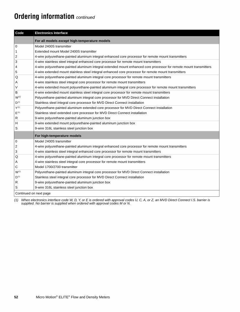
52 Micro Motion® ELITE® Flow and Density Meters
Ordering information continued
Code Electronics Interface
For all models except high-temperature models
0 Model 2400S transmitter
1 Extended mount Model 2400S transmitter
2 4-wire polyurethane-painted aluminum integral enhanced core processor for remote mount transmitters
3 4-wire stainless steel integral enhanced core processor for remote mount transmitters
4 4-wire polyurethane-painted aluminum integral extended mount enhanced core processor for remote mount transmitters
5 4-wire extended mount stainless steel integral enhanced core processor for remote mount transmitters
Q 4-wire polyurethane-painted aluminum integral core processor for remote mount transmitters
A 4-wire stainless steel integral core processor for remote mount transmitters
V 4-wire extended mount polyurethane-painted aluminum integral core processor for remote mount transmitters
B 4-wire extended mount stainless steel integral core processor for remote mount transmitters
W(1)
(1) When electronics interface code W, D, Y, or E is ordered with approval codes U, C, A, or Z, an MVD Direct Connect I.S. barrier is supplied. No barrier is supplied when ordered with approval codes M or N.
Polyurethane-painted aluminum integral core processor for MVD Direct Connect installation
D(1) Stainless steel integral core processor for MVD Direct Connect installation
Y(1) Polyurethane-painted aluminum extended core processor for MVD Direct Connect installation
E(1) Stainless steel extended core processor for MVD Direct Connect installation
R 9-wire polyurethane-painted aluminum junction box
H 9-wire extended mount polyurethane-painted aluminum junction box
S 9-wire 316L stainless steel junction box
For high-temperature models
0 Model 2400S transmitter
2 4-wire polyurethane-painted aluminum integral enhanced core processor for remote mount transmitters
3 4-wire stainless steel integral enhanced core processor for remote mount transmitters
Q 4-wire polyurethane-painted aluminum integral core processor for remote mount transmitters
A 4-wire stainless steel integral core processor for remote mount transmitters
C Model 1700/2700 transmitter
W(1) Polyurethane-painted aluminum integral core processor for MVD Direct Connect installation
D(1) Stainless steel integral core processor for MVD Direct Connect installation
R 9-wire polyurethane-painted aluminum junction box
S 9-wire 316L stainless steel junction box
Continued on next page
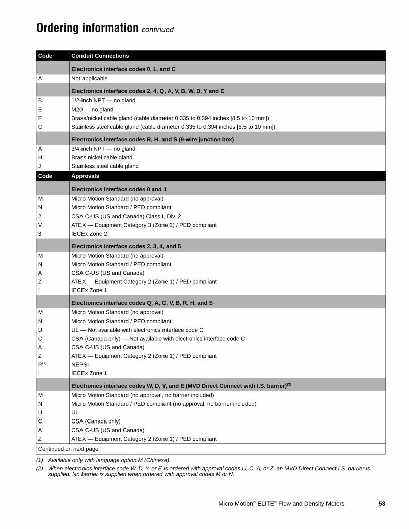
Micro Motion® ELITE® Flow and Density Meters 53
Ordering information continued
Code Conduit Connections
Electronics interface codes 0, 1, and C
A Not applicable
Electronics interface codes 2, 4, Q, A, V, B, W, D, Y and E
B 1/2-inch NPT — no gland
E M20 — no gland
F Brass/nickel cable gland (cable diameter 0.335 to 0.394 inches [8.5 to 10 mm])
G Stainless steel cable gland (cable diameter 0.335 to 0.394 inches [8.5 to 10 mm])
Electronics interface codes R, H, and S (9-wire junction box)
A 3/4-inch NPT — no gland
H Brass nickel cable gland
J Stainless steel cable gland
Code Approvals
Electronics interface codes 0 and 1
M Micro Motion Standard (no approval)
N Micro Motion Standard / PED compliant
2 CSA C-US (US and Canada) Class I, Div. 2
V ATEX — Equipment Category 3 (Zone 2) / PED compliant
3 IECEx Zone 2
Electronics interface codes 2, 3, 4, and 5
M Micro Motion Standard (no approval)
N Micro Motion Standard / PED compliant
A CSA C-US (US and Canada)
Z ATEX — Equipment Category 2 (Zone 1) / PED compliant
I IECEx Zone 1
Electronics interface codes Q, A, C, V, B, R, H, and S
M Micro Motion Standard (no approval)
N Micro Motion Standard / PED compliant
U UL — Not available with electronics interface code C
C CSA (Canada only) — Not available with electronics interface code C
A CSA C-US (US and Canada)
Z ATEX — Equipment Category 2 (Zone 1) / PED compliant
P(1)
(1) Available only with language option M (Chinese).
NEPSI
I IECEx Zone 1
Electronics interface codes W, D, Y, and E (MVD Direct Connect with I.S. barrier)(2)
(2) When electronics interface code W, D, Y, or E is ordered with approval codes U, C, A, or Z, an MVD Direct Connect I.S. barrier is supplied. No barrier is supplied when ordered with approval codes M or N.
M Micro Motion Standard (no approval, no barrier included)
N Micro Motion Standard / PED compliant (no approval, no barrier included)
U UL
C CSA (Canada only)
A CSA C-US (US and Canada)
Z ATEX — Equipment Category 2 (Zone 1) / PED compliant
Continued on next page

54 Micro Motion® ELITE® Flow and Density Meters
Ordering information continued
Code Language
A Danish installation manual
D Dutch installation manual
E English installation manual
F French installation manual
G German installation manual
H Finnish installation manual
I Italian installation manual
J Japanese installation manual
M Chinese installation manual
N Norwegian installation manual
O Polish installation manual
P Portuguese installation manual
S Spanish installation manual
W Swedish installation manual
C Czech installation manual
B Hungarian CE requirements document and English installation manual
K Slovak CE requirements document and English installation manual
T Estonian CE requirements document and English installation manual
U Greek CE requirements document and English installation manual
L Latvian CE requirements document and English installation manual
V Lithuanian CE requirements document and English installation manual
Y Slovenian CE requirements document and English installation manual
Code(1)
(1) Calibration options other than Z require electronics interface codes 0–5. In addition, for high-temperature models, only calibration option Z is available.
Calibration Options
Z 0.10% mass flow and 0.0005 g/cm3 (0.5 kg/m3) density
D 0.10% mass flow and 0.0002 g/cm3 (0.2 kg/m3) density
2 0.05% mass flow and 0.0005 g/cm3 (0.5 kg/m3) density
3 0.05% mass flow and 0.0002 g/cm3 (0.2 kg/m3) density
Code Measurement Application Software
Z No measurement application software
A(2)
(2) Available with electronics interface code W, D, Y, and E. For electronics interface codes 0–5, Q, A, V, B, R, H, and S, select the transmitter’s Petroleum Measurement software option.
Petroleum measurement
Code Factory Options
Z Standard product
X ETO product
Typical Model Number: CMF050M 313 N 2 B A E Z Z Z

Micro Motion® ELITE® Flow and Density Meters 55
Emerson Process ManagementMicro Motion AmericasWorldwide Headquarters7070 Winchester CircleBoulder, Colorado USA 80301T: 800 522 6277T: +1 (303) 527 5200F: +1 (303) 530 8459Mexico T: 52 55 5366 2622Argentina T: 54 11 4837 7000Brazil T: 55 15 3238 3677Venezuela T: 58 26 1731 3394
Emerson Process ManagementMicro Motion Europe/Middle EastCentral & Eastern Europe T: +41 41 7686 111Dubai T: 971-4 8835235France T: 0800 917 901Germany T: 0800 182 5347Italy T: 8008 77334The Netherlands T: (31) 318 495 555U.K. T: 0870 240 1978Russia/CIS T: +7 495 981 9811
Emerson Process ManagementMicro Motion Asia PacificAustralia T: (61) 3 9721 0200China T: (86) 21 3895 4788India T: (91) 22 5662 0566Japan T: (81) 3 5769 6803Korea T: (82) 2 3438 4600Singapore T: (65) 6 777 8211
Micro Motion—The undisputed leader in flow and density measurement
WWW.micromotion.com
World-leading Micro Motion measurement solutions from Emerson Process Management deliver what you need most:
Technology leadershipMicro Motion introduced the first reliable Coriolis meter in 1977. Since that time, our ongoing product development has enabled us to provide the highest performing measurement devices available.
Product breadthFrom compact, drainable process control to high flow rate fiscal transfer—look no further than Micro Motion for the widest range of measurement solutions.
Unparalleled valueBenefit from expert phone, field, and application service and support made possible by more than 500,000 meters installed worldwide and 30 years of flow and density measurement experience.
© 2007 Micro Motion, Inc. All rights reserved. Micro Motion is committed to continuous product improvement. As a result, all specifications are subject to change without notice. ELITE and ProLink are registered trademarks, and MVD and MVD Direct Connect are trademarks of Micro Motion, Inc., Boulder, Colorado. Micro Motion is a registered trade name of Micro Motion, Inc., Boulder, Colorado. The Micro Motion and Emerson logos are trademarks and service marks of Emerson Electric Co. All other trademarks are property of their respective owners.