elps series 4 - power systems international
TRANSCRIPT

ELPS SERIES 4 Point of use power for Emergency Evacuation Lifts Established in 1986 the company offers a power solution for meeting the emergency power requirements of Evacuation Lifts as defined in the Disability Discrimination Act of 1995 and the Regulatory Reform (Fire Safety) Order of 2005. The ELPS is also compliant with BS9999:2017. The Power Systems International team works closely with Lift manufacturers, Local Authority Fire Safety Officers, Consulting Engineers and Architects to determine the best cost-effective means to deliver power “on demand” to a dedicated evacuation lift in an emergency when normal operations are halted. The new Series 4 ELPS product is a “Black Box” point of use power system to feed VVVF lift hoisting or hydraulic systems.
ABOUT THE PRODUCT
The ELPS Series 4 evacuation lift power system is designed for positioning as close as possible to the lift in a well ventilated indoors location. Installation is quick and simple and therefore the cable runs are short and less exposed to the risk of theft, vandalism or sabotage, risks that exist with “centralised” back-up power systems. The ELPS is supplied with a length of flexible cable for input and output terminated with a CEE17 plug and socket. The package is provided with a “manual bypass box” for installation by the electrical contractor. This box is fitted with the mating plug and socket into which the flexible input and output cables of the ELPS are to be inserted.
ELPS
The ELPS is available in six power capacities of 10, 15, 20, 30, 40 and 60kVA, though other sizes can be supplied upon request, all are suitable for use with mains power of 50Hz 400VAC/415VAC three phase input and output with the output having a protective earth. The inverter is designed to accommodate the unpredictable load of most passenger lifts with weights up to 1600kg. Our team will work with you to determine the correct sizing based on how many landing stops and starts per hour, how many passengers in the lift car in the upward elevation and on the descending journey. How long the lift will remain on a landing with the doors held open to allow disabled persons in wheel chairs be accommodated with dignity. The overall aim is to ensure that the ELPS can handle its minimum required evacuation duty of 10 upward and 10 downward journeys over the required number of landings in a period of 60 minutes.
HOW THE ELPS WORKS... In order to comply with the current legislation, we provide a key operated switch (located by the lift). The key switch is intended so that only an authorised person can operate the lift in an evacuation. When the key is turned it starts the power to the lift much as turning the key in the car starts the engine. The electrical contractor will need to install a suitable 5 cores signal cable from the ELPS to the remote-control point. The lift manufacturer will also need to take this signal into the lift control panel for the lift operator to observe the "on emergency power" status alarm. The ELPS can be also be provided with an optional automatic control feature that allows the inverter to start upon sensing the loss of mains power (or other source) at the input terminals of the ELPS. A signal will be provided to indicate the inverter is operating.
ELP
S SE
RIE
S 4

INSTALLATION The wall mounting dual purpose manual wrap around bypass box is as close as we can get to providing a “plug and play” simple and quick installation facility for connecting up the ELPS product to the mains power and to the lift traction system. The box will be delivered ahead of the ELPS unit so the electrical contractor can complete the installation of the box and fix all the cables without having the inconvenience of working around an obstructive “box” in the working area. This wall mounting box is fitted with the plug and sockets into which the flexible input and output cables of the ELPS are to be inserted.
CONNECTING THE ELPS TO THE MAINS AND TO THE LIFT
Each unit is tested in our facility with the batteries that will be used for that specific installation. In this way we know that the unit works in that configuration before it leaves us. The ELPS will be delivered to site with the batteries but without the batteries being installed. The ELPS will be placed in its final operating place with the battery bank and correct internal connections, the plug and socket terminated flexible input and output cables stowed at the rear of the unit plugged into the bypass box fitted on the wall. When the bypass switch is in the normal position the mains power feeds the ELPS input and battery charger. The ELPS output circuit is connected to the lift traction system and controller.
THE EMERGENCY There are many emergencies which may result in a building or part of a building needing to be evacuated. These emergencies are not just restricted to fire, earthquake tremors, explosion, a security threat, impact damage from crashing vehicle, flooding, storm damage, chemical, gas or other vapour release into the atmosphere.
The likelihood of one or more of these occurrences leading to an emergency call to evacuate will vary depending on the location and the use of the building. The majority of emergency considerations in the UK over the past 10 years have focused on fire, toxic fumes and smoke emission and the exceptional storm water flooding and mains power line failures over the winter of 2014. The familiar warning sign asking occupiers not to use lifts in an emergency is often specifically about a fire emergency. At the discretion of official policy relating to Public Buildings it might be permitted to use an appropriate lift under supervision for the evacuation of disabled persons where it is recognised there is a daunting and virtually impossible task to use exit flights of stairs for a quick exit of wheel chair bound persons.
The decision would have to be made based on the threat to life in using a suitable lift, possibly a lift that is a distance away from the reported emergency and where the risk is adjudged to be less than staying in the building or evacuating personnel into an unknown hazard area. The ELPS will, however detect a mains failure and be automatically ready to deliver power to the point needed. Where there was a fire in an electricity sub-station or in a distribution board feeding power to the building, this would most likely have initiated an alarm and the command for the system to start up and take over from the substation or Ring Main power supply.
It is important to minimize the cable lengths to reduce the risks of damage.
The advantage of the ELPS unit is it can be located close to the source of power feeding the lift or even to fans needed for a safe refuge area.
The ELPS is the obvious solution>>>>
The ELPS “point of use” product from Power Systems International is the more secure and better cost-effective means of providing power to make the difference for emergency evacuation lifts:
• The ELPS delivers power when it is needed.
• The ELPS delivers power to the point where it is needed.
No exhaust fumes, no smell, no diesel fuel or gas storage, no risk of fuel spillage, no noise, no environmental pollution…The ELPS just needs a little energy to keep the internal batteries charged ready for the emergency!...Perhaps, a “no brainer” choice for the decision maker!
ELP
S SE
RIE
S 4

INSTALLATION DRAWING
EL
PS
INST
ALL
ATI
ON
DR
AW
ING

TECHNICAL SPECIFICATIONS The specification of the ELPS-10T (10kVA) standby power system is as follows:
INPUT
Nominal voltage: 3 x 400 and neutral ±15%
Nominal Frequency: 50Hz
Max Input current at full load: 3 x 14 A
Power Rating 10kVA Consumption in Stand-by mode: 50 Watts
OUTPUT
Voltage: 3 phase x 400 V and neutral
Voltage stability by inverter: 1 %
Frequency: 50Hz
Frequency stability: 0.001 %
Wave form: Sinusoidal < 2% THD
Efficiency (stand-by mode): 99.7
% Losses (with load fed via batteries): 693 kcal/h
Max Output current at full load: 3 x 15.2 A
BATTERY
Rated Voltage: 272 VDC
Cells/Blocks: 2 x 20 x 12V (each cabinet)
Battery design life: 10 years (BS6290 part 4)
Autonomy: 10 evacuation journeys within 60 minutes
MECHANICAL AND ENVIRONMENTAL DATA ELPS power system dimensions: (mm) 1,320H x 440W x 850D* Weight of ELPS, without batteries: 105 Kg approx.
Battery Cabinet: (m) 1,320H x 440W x 850D
Weight of battery cabinet (19AH): 205 Kg approx.
Wall Mounting Box Wrap Around
Bypass dimensions: (mm) 600H x 400W x 250D*
Wall Mounting Box Wrap
Around Bypass weight: 10 Kg
Noise level measured at 1 metre: 40dBA, (no load) 50dBA
(fullload)
Ambient temperature: 0°C to 40°C for power unit. 0˚C
to 23˚C, optimum for battery.
Relative humidity: 0 to 95 % non-condensing.
Ingress protection: IP 20 (IEC 529)
Applicable Standards: EN50091, EN60950, EN61000,
BS9999:20
* to be confirmed at ordering stage
ELP
S-1
0T

The specification of the ELPS-15T (15kVA) standby power system is as follows:
INPUT Nominal voltage: 3 x 400 and neutral ±15%
Nominal Frequency: 50Hz
Max Input current at full load: 3 x 22 A
Power Rating 15kVA Consumption in Stand-by mode: 50 Watts
OUTPUT
Voltage: 3 phase x 400 V and neutral
Voltage stability by inverter: 1 %
Frequency: 50Hz
Frequency stability: 0.001 %
Wave form: Sinusoidal < 2% THD
Efficiency (stand-by mode): 99.7
% Losses (with load fed via batteries): 693 kcal/h
Max Output current at full load: 3 x 15.2 A
BATTERY
Rated Voltage: 432 V DC or 624V DC
Cells/Blocks: 192/32 x 12V or 312/52 x 12V
Battery design life: 10 years (BS6290 part 4)
Autonomy: 10 evacuation journeys within 60 minutes.
MECHANICAL AND ENVIRONMENTAL DATA ELPS power system dimensions: (mm) 1,320H x 440W x 850D*
Weight of ELPS, without batteries: 115 Kg approx.
Battery Cabinet: (mm) 1,320H x 440W x 850D
Weight of battery cabinet (27AH): 300 Kg approx.
Wall Mounting Box Wrap Around
Bypass dimensions: (mm) 600H x 400W x 250D*
Wall Mounting Box Wrap
Around Bypass weight: 10 Kg
Noise level measured at 1 metre: 40dBA, (no load) 50dBA (full
load)
Ambient temperature: 0°C to 40°C for power unit.
0˚C to 23˚C, optimum for
battery.
Relative humidity: 0 to 95 % non-condensing.
Ingress protection: IP 20 (IEC 529)
Applicable Standards: EN50091, EN60950, EN61000,
BS9999:2017 * to be confirmed at ordering stage
ELPS-
15
T

The specification of the ELPS-20T (20kVA) standby power system is as follows:
INPUT
Nominal voltage: 3 x 400 and neutral ±15%
Nominal Frequency: 50Hz
Max Input current at full load: 3 x 29 A
Power Rating 20kVA Consumption in Stand-by mode: 50 Watts
OUTPUT
Voltage: 3 phase x 400 V and neutral
Voltage stability by inverter: 1 %
Frequency: 50Hz
Frequency stability: 0.001 %
Wave form: Sinusoidal < 2% THD
Efficiency (stand-by mode): 99.7
% Losses (with load fed via batteries): 693 kcal/h
Max Output current at full load: 3 x 15.2 A
BATTERY Rated Voltage: 272 VDC
Cells/Blocks: 2 x 20 x 12V (each cabinet)
Battery design life: 10 years (BS6290 part 4)
Autonomy: 10 evacuation journeys within 60 minutes. [g]
MECHANICAL AND ENVIRONMENTAL DATA ELPS power system dimensions: (mm) 1,320H x 440W x 850D*
Weight of ELPS, without batteries: 120 Kg approx.
Battery Cabinet: (mm) 1,320H x 440W x 850D
Weight of battery cabinet (27AH): 300 Kg approx.
Wall Mounting Box Wrap
Around Bypass dimensions: (mm) 600H x 400W x 250D*
Wall Mounting Box Wrap
Around Bypass weight: 10 Kg
Noise level measured at 1 metre: 40dBA, (no load) 50dBA (full
load)
Ambient temperature: 0°C to 40°C for power unit.
0˚C to 23˚C, optimum for
battery.
Relative humidity: 0 to 95 % non-condensing.
Ingress protection: IP 20 (IEC 529)
Applicable Standards: EN50091, EN60950, EN61000,
BS9999:2017 * to be confirmed at ordering stage
ELPS-
20
T

The specification of the ELPS-30T (30kVA) standby power system is as follows:
INPUT
Nominal voltage: 3 x 400 and neutral ±15%
Nominal Frequency: 50Hz
Max Input current at full load: 3 x 43 A
Power Rating 30kVA Consumption in Stand-by mode: 100 Watts
OUTPUT
Voltage: 3 phase x 400 V and neutral
Voltage stability by inverter: 1 %
Frequency: 50Hz
Frequency stability: 0.001 %
Wave form: Sinusoidal < 2% THD
Efficiency (stand-by mode): 99.7
% Losses (with load fed via batteries): 693 kcal/h
Max Output current at full load: 3 x 15.2 A
BATTERY
Rated Voltage: 272 VDC
Cells/Blocks: 2 x 20 x 12V (each cabinet)
Battery design life: 10 years (BS6290 part 4)
Autonomy: 10 evacuation journeys within 60 minutes
MECHANICAL AND ENVIRONMENTAL DATA ELPS power system dimensions: (mm) 1,320H x 440W x 850D*
Weight of ELPS, without batteries: 125 Kg approx.
Battery Cabinet: (mm) 1,320H x 440W x 850D
Weight of battery cabinet (27AH): 300 Kg approx.
Wall Mounting Box Wrap Around
Bypass dimensions: (mm) 600H x 400W x 250D*
Wall Mounting Box Wrap Around
Bypass weight: 10 Kg
Noise level measured at 1 metre: 40dBA, (no load) 50dBA (full
load)
Ambient temperature: 0°C to 40°C for power unit.
0˚C to 23˚C, optimum for
battery.
Relative humidity: 0 to 95 % non-condensing.
Ingress protection: IP 20 (IEC 529)
Applicable Standards: EN50091, EN60950, EN61000,
BS9999:2017
* to be confirmed at ordering sta
ELP
S-3
0T

The specification of the ELPS-40T (40kVA) standby power system is as follows:
INPUT
Nominal voltage: 3 x 400 and neutral ±15%
Nominal Frequency: 50Hz
Max Input current at full load: 3 x 58 A
Power Rating 40kVA
Consumption in Stand-by mode: 100 Watts
OUTPUT
Voltage: 3 phase x 400 V and neutral
Voltage stability by inverter: 1 %
Frequency: 50Hz
Frequency stability: 0.001 %
Wave form: Sinusoidal < 2% THD
Efficiency (stand-by mode): 99.7
% Losses (with load fed via batteries): 693 kcal/h
Max Output current at full load: 3 x 15.2 A
BATTERY
Rated Voltage: 272 VDC
Cells/Blocks: 2 x 20 x 12V (each cabinet)
Battery design life: 10 years (BS6290 part 4)
Autonomy: 10 evacuation journeys within 60
minutes.
MECHANICAL AND ENVIRONMENTAL DATA
ELPS power system dimensions: (mm) 1,320H x 440W x 850D*
Weight of ELPS, without batteries: 135 Kg approx.
Battery Cabinet (mm) 1,320H x 440W x 850D
Weight of battery cabinet (27AH): 300 Kg approx.
Wall Mounting Box Wrap Around
Bypass dimensions: (mm) 600H x 400W x 250D*
Wall Mounting Box Wrap Around
Bypass weight: 10 Kg
Noise level measured at 1 metre: 40dBA, (no load) 50dBA (full load)
Ambient temperature: 0°C to 40°C for power unit.
0˚C to 23˚C, optimum for battery.
Relative humidity: 0 to 95 % non-condensing.
Ingress protection: IP 20 (IEC 529)
Applicable Standards: EN50091, EN60950, EN61000,
BS9999:20
* to be confirmed at ordering stage.
ELP
S-4
0T

The specification of the ELPS-60T (60kVA) standby power system is as follows:
INPUT Nominal voltage: 3 x 400 and neutral ±15%
Nominal Frequency: 50Hz
Max Input current at full load: 3 x 87 A
Power Rating 60kVA Consumption in Stand-by mode: 100 Watts
OUTPUT
Voltage: 3 phase x 400 V and neutral
Voltage stability by inverter: 1 %
Frequency: 50Hz
Frequency stability: 0.001 %
Wave form: Sinusoidal < 2% THD
Efficiency (stand-by mode): 99.7
% Losses (with load fed via batteries): 693 kcal/h
Max Output current at full load: 3 x 15.2 A
BATTERY
Rated Voltage: 272 VDC
Cells/Blocks: 2 x 20 x 12V (each cabinet)
Battery design life: 10 years (BS6290 part 4)
Autonomy: 10 evacuation journeys within 60 minutes.
MECHANICAL AND ENVIRONMENTAL DATA ELPS power system dimensions: (mm) 1,600H x 500W x 850D*
Weight of ELPS, without batteries: 140 Kg approx.
Battery Cabinet: (mm) 1,320H x 440W x 850D
Weight of battery cabinet (27AH): 300 Kg approx.
Wall Mounting Box Wrap Around
Bypass dimensions: (mm) 600H x 400W x 250D*
Wall Mounting Box Wrap Around
Bypass weight: 10 Kg
Noise level measured at 1 metre: 40dBA, (no load) 50dBA (full
load)
Ambient temperature: 0°C to 40°C for power unit.
0˚C to 23˚C, optimum for
battery.
Relative humidity: 0 to 95 % non-condensing.
Ingress protection: IP 20 (IEC 529)
Applicable Standards: EN50091, EN60950, EN61000,
BS9999:2017
* to be confirmed at ordering stage
ELP
S-6
0T

The specification of the ELPS-80T (80kVA) standby power system is as follows:
INPUT
Nominal voltage: 3 x 400 and neutral ±15%
Nominal Frequency: 50Hz
Max Input current at full load: 3 x 115 A
Power Rating 80kVA Consumption in Stand-by mode: 100 Watts
OUTPUT
Voltage: 3 phase x 400 V and neutral
Voltage stability by inverter: 1 %
Frequency: 50Hz
Frequency stability: 0.001 %
Wave form: Sinusoidal < 2% THD
Efficiency (stand-by mode): 99.7
% Losses (with load fed via batteries): 693 kcal/h
Max Output current at full load: 3 x 15.2
BATTERY Rated Voltage: 272 VDC
Cells/Blocks: 2 x 20 x 12V (each cabinet)
Battery design life: 10 years (BS6290 part 4)
Autonomy: 10 evacuation journeys within 60 minutes
MECHANICAL AND ENVIRONMENTAL DATA ELPS power system dimensions: (mm) 1,600H x 500W x 850D*
Weight of ELPS, without batteries: 160 Kg approx.
Battery Cabinet: (mm) 1,320H x 440W x 850D
Weight of battery cabinet (27AH): 300 Kg approx.
Wall Mounting Box Wrap Around
Bypass dimensions: (mm) 600H x 400W x 250D*
Wall Mounting Box Wrap Around
Bypass weight: 10 Kg
Noise level measured at 1 metre: 40dBA, (no load) 50dBA (full
load)
Ambient temperature: 0°C to 40°C for power unit.
0˚C to 23˚C, optimum for
battery.
Relative humidity: 0 to 95 % non-condensing.
Ingress protection: IP 20 (IEC 529)
Applicable Standards: EN50091, EN60950, EN61000,
BS9999:2017
* to be confirmed at ordering stage
ELPS-
80
T

The specification of the ELPS-100T (100kVA) standby power system is as follows: INPUT Nominal voltage: 3 x 400 and neutral ±15%
Nominal Frequency: 50Hz
Max Input current at full load: 3 x 115 A
Power Rating: 100kVA
Consumption in Stand-by mode: 100 Watts
OUTPUT Voltage: 3 phase x 400 V and neutral Voltage stability by inverter: 1 % Frequency: 50Hz Frequency stability: 0.001 % Wave form: Sinusoidal < 2% THD Efficiency (stand-by mode): 99.7 % Losses (with load fed via batteries): 693 kcal/h Max Output current at full load: 3 x 15.2 A
BATTERY Rated Voltage: 272 VDC
Cells/Blocks: 2 x 20 x 12V (each cabinet)
Battery design life: 10 years (BS6290 part 4)
Autonomy: 10 evacuation journeys within
60 minutes.
MECHANICAL AND ENVIRONMENTAL DATA ELPS power system dimensions: (mm) 1,600H x 500W x 850D*
Weight of ELPS, without batteries: 220 Kg approx.
Battery Cabinet: (mm) 1,320H x 440W x 850D
Weight of battery cabinet (27AH): 300 Kg approx.
Wall Mounting Box Wrap Around
Bypass dimensions: (mm) 600H x 400W x 250D*
Wall Mounting Box Wrap Around
Bypass weight: 10 Kg
Noise level measured at 1 metre: 40dBA, (no load) 50dBA (full
load)
Ambient temperature: 0°C to 40°C for power unit.
0˚C to 23˚C, optimum for
battery.
Relative humidity: 0 to 95 % non-condensing.
Ingress protection: IP 20 (IEC 529)
Applicable Standards: EN50091, EN60950, EN61000,
BS9999:2017
ELPS-
10
0T

* to be confirmed at ordering stage
Battery weights and cabinets vary based on how long the lift needs to operate and therefore the Amp Hour specification of the battery. Weights will vary dependng on the size required. Battery upto 18AH can be contained in the cabinet provided. However larger sizes will require an additonal battery cabinet, this to be confirmed on ordering.
Longer automony (running time) are available upon request
ELPS-
10
0T

SINGLE LINE DRAWINGS
ELP
S-SL
D1

ELP
S-SL
D2

ELP
S-SL
D3

D a
t e:
R e
v i s
i o n
:
P r
o j e
c t:
D r
a w
i n g
T i t
l e:
R e
v i s
i o n
n o
t e
s:
Rev
:D
ate:
No
tes:
Dra
wn
by
:
Clie
nt:
ELP
S-B
YPA
SS W
IRIN
G

INSTALLATION AND OPERATION MANUAL
MAINTENANCE BYPASS SWITCH
SINGLE AND THREE PHASE SYSTEMS

1) INTRODUCTION
The Maintenance Bypass Switch (MBS) is a wall mounted unit specially designed to allow maintenance and removal of the UPS without disruption of the supply to the protected equipment (i.e. the load). The MBS can also be used to test and commission the ELPS system without affecting the load. It is fitted with three switches that can be in 2 positions only (OFF (0) and ON (1)). Care must be taken to follow the operating instructions to prevent accidental switching during normal and bypass operation. With the MBS in normal configuration, backup is available from the ELPS in the event or a mains supply failure. When in bypass configuration, no backup is available, but the mains supply can remain connected to the ELPS if required.
2) INSTALLATION WARNING: The following procedure must be followed exactly. Failure to do so, could lead to exposure to hazardous voltages and disruption of the protected equipment. It is recommended that the following procedure is only carried out by a qualified electrician.
***THIS EQUIPMENT MUST BE EARTHED***
Before commencing the installation ensure that the MBS is suitable for the ELPS system for which it is to be used. The connection cable sizes can be found in the ELPS user manual. Mount the MBS securely to an even surface (e.g. wall); this can be achieved using the four mounting holes located in the rear of the enclosure. Once the MBS is securely mounted the connections can be made as described in the next section. The removable gland plates must be drilled to suit your particular gland requirements.
3) CONNECTION OF THE MAINS SUPPLY
Feed the mains supply cables through the gland plate and secure, terminate the mains supply cables to the terminals marked “MAINS INPUT” as follows:

1) CONNECTION OF THE INPUT TO THE ELPS Feed the ELPS input cables through the gland plate and secure, terminate the ELPS input cables to the terminals marked “UPS INPUT” as follows:
2) CONNECTION OF THE OUTPUT FROM THE ELPS Feed the ELPS output cables through the gland plate and secure, terminate the UPS output cables to the terminals marked “UPS OUTPUT” as follows:
3) CONNECTION OF THE PROTECTED EQUIPMENT Feed the protected equipment cables through the gland plate and secure, terminate marked “LOAD OUTPUT” as follows:

7) CONNECTION OF THE AUXILIARY CONTACTS (OPTIONAL) The auxiliary Contacts are only used if required. They allow the position of bypass switch to be monitored as follows- Contact Rating: 20amps @ 230Vac. /20amps
8) INITIAL SWITCH ON Before the mains supply is applied to the MBS, refit all of the covers that were removed during installation, not forgetting the earth connections. All three switches should be in the OFF (0) position. With the supply available to the MBS, closing the BYPASS switch to the ON (1) position will energise the load circuits down-stream of the panel. Turning the UPS INPUT switch to the ON (1) position will provide power to the ELPS. Start the ELPS and confirm that the ELPS operates correctly as described in its User Manual. Place the ELPS into bypass mode, referring to the ELPS operation manual if necessary. Close the UPS OUTPUT switch to the ON (1)
position, and then open the BYPASS switch to the OFF (0) position on the MBS. Transfer the ELPS from bypass to online mode. The ELPS is now supporting the load circuit, and the system is in the normal operating mode.
9) CONNECTION OF THE AUXILIARY CONTACTS (OPTIONAL)
The auxiliary Contacts are only used if required. They allow the position of bypass switch to be monitored as follows- Contact Rating: 20amps @ 230Vac. /20amps
10) INITIAL SWITCH ON
Before the mains supply is applied to the MBS, refit all of the covers that were removed during installation, not forgetting the earth connections. All three switches should be in the OFF (0) position. With the supply available to the MBS, closing the BYPASS switch to the ON (1) position will energise the load circuits down-stream of the panel. Turning the UPS INPUT switch to the ON. (1)position will provide power to the ELPS. Start the ELPS and confirm that the ELPS operates correctly as described in its User Manual. Place the ELPS into bypass mode, referring to the ELPS operation manual if necessary. Close the UPS OUTPUT switch to the ON (1) position, and then open the BYPASS switch to the OFF (0) position on the MBS. Transfer the ELPS from bypass to online mode. The ELPS is now supporting the load circuit, and the system is in the normal operating mode.
11) MAINTENANCE BYPASS SWITCH OPERATION
Switching to Bypass Operation (for ELPS maintenance and testing only)
Note: - Check that the ELPS is working normally and that it is not working in battery operation mode (refer to ELPS user manual). If these conditions are not met, disruption or even damage can occur to the ELPS or protected load if the switch is operated.
a) Transfer the ELPS to bypass operation, referring to the ELPS operation manual if necessary. b) Turn the BYPASS switch to ON (1) position. c) Turn the UPS OUTPUT switch to OFF (0) position. The load is now supplied directly from the mains supply and the ELPS still has mains supply connected. The ELPS may now be switched off or tested (refer to UPS user manual) without disrupting the load.
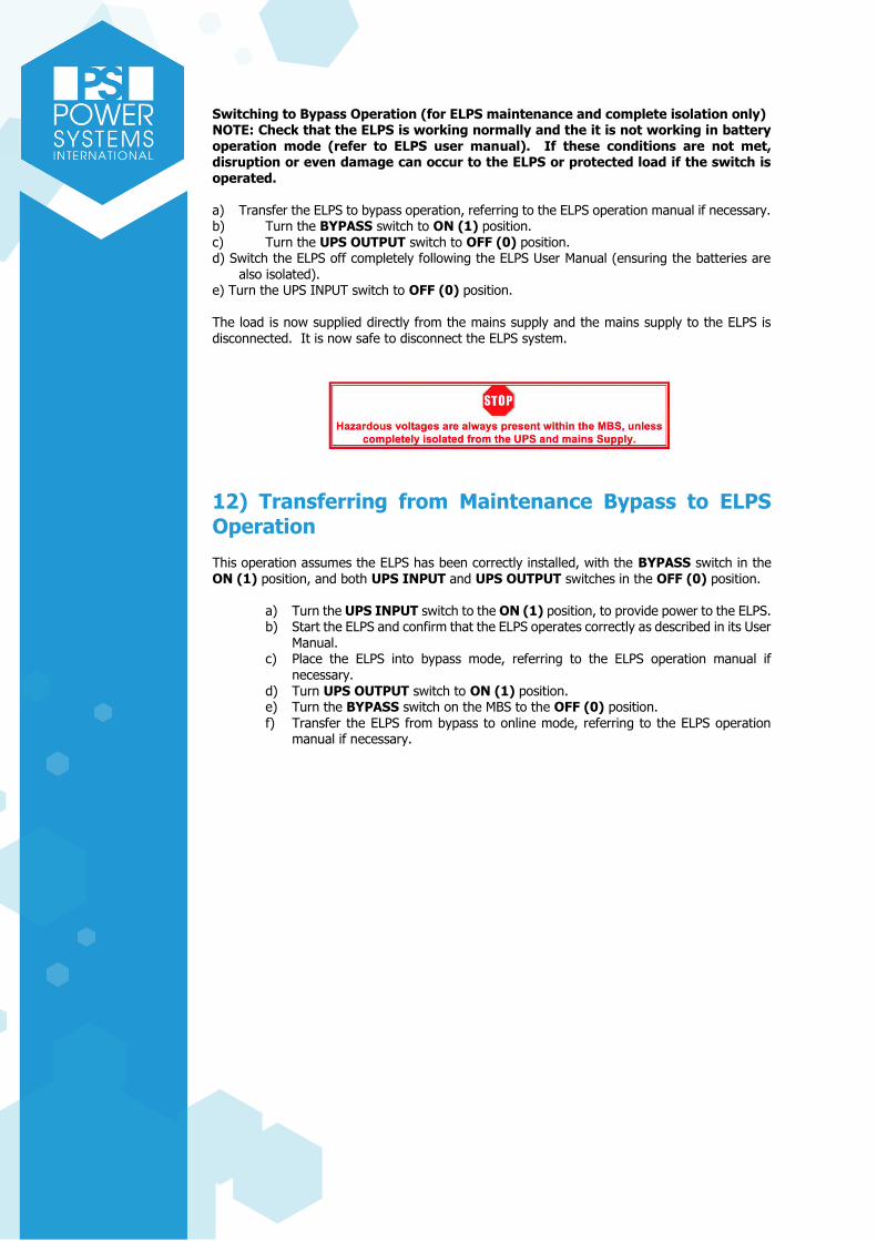
Switching to Bypass Operation (for ELPS maintenance and complete isolation only) NOTE: Check that the ELPS is working normally and the it is not working in battery operation mode (refer to ELPS user manual). If these conditions are not met, disruption or even damage can occur to the ELPS or protected load if the switch is operated. a) Transfer the ELPS to bypass operation, referring to the ELPS operation manual if necessary. b) Turn the BYPASS switch to ON (1) position. c) Turn the UPS OUTPUT switch to OFF (0) position. d) Switch the ELPS off completely following the ELPS User Manual (ensuring the batteries are
also isolated). e) Turn the UPS INPUT switch to OFF (0) position.
The load is now supplied directly from the mains supply and the mains supply to the ELPS is disconnected. It is now safe to disconnect the ELPS system.
12) Transferring from Maintenance Bypass to ELPS Operation This operation assumes the ELPS has been correctly installed, with the BYPASS switch in the ON (1) position, and both UPS INPUT and UPS OUTPUT switches in the OFF (0) position.
a) Turn the UPS INPUT switch to the ON (1) position, to provide power to the ELPS. b) Start the ELPS and confirm that the ELPS operates correctly as described in its User
Manual. c) Place the ELPS into bypass mode, referring to the ELPS operation manual if
necessary. d) Turn UPS OUTPUT switch to ON (1) position. e) Turn the BYPASS switch on the MBS to the OFF (0) position. f) Transfer the ELPS from bypass to online mode, referring to the ELPS operation
manual if necessary.

SUGGESTED OPERATING
PROTOCOL FOR EVACUATION
LIFTS POWER SYSTEMS INTERNATIONAL LIMITED Industrial Rectifiers, Inverters, UPS & ELPS systems and Frequency converters Carina House East, Sunrise Parkway, Linford Wood, Milton Keynes, Bucks. MK14 6LS. England. Tel. + 441494871544 Fax. + 441494873118 http://www.powersystemsinternational.com/
EVACUATION LIFT RECOMMENDED OPERATING PROTOCOL

BACKGROUND In order to support the correct operation of a lift in evacuation mode, we provide the
following protocol to be used for the operation of an evacuation lift in the event of use.
This is the responsibility of the lift company and not Power Systems International
Limited (PSI) or PSI Lifts Limited (PSIL). Moreover, this is guidance and no reliance can
be placed nor inferred from this protocol.
What we are providing is an example of what in our opinion is best practice and it is the
ultimate client’s responsibility to ensure that any evacuation procedures and protocol are
fit for purpose.
PROTOCOL
We have used the lift system at Garth Building, Bangor University based on the design for
those lifts, the lift equipment and our secondary power systems.
Recommended Lift Evacuation Protocol
The system is integrated with the ELPS unit; with the lift control working as follows: On
activation from the building fire alarm or on the event of a switch from normal operation
to evacuation mode on the landing station.
1. The lifts, if in travel will continue to the destination and complete a controller
stop (doors do not open). Landing call buttons are disabled.
2. The display within the cabins and on the landings will display: “Lift in Evacuation
mode”. This is also repeated on the lift cabin speech system. With this installation,
Welsh practice adopted in the Garth Building lifts, require that this is repeated in
Welsh. Other secondary languages might be required in public places, though there
is no requirement for this.
3. The lifts return to the main exit level and stay parked there with the doors open. If
a fire signal is detected on the main floor the lift will return to the second option
level.
4. The displays on the landings and cabin show lift position and Lift in evacuation
mode, when the lift travels the direction arrows show direction of lift and floor
level.
5. The evacuation procedure is for two people: operative one at the main control
station receiving calls from the landing intercoms and one operative as lift driver.
Communication between operatives is via cabin intercom and main station.
6. The lift driver using the evacuation control key in the cabin COP takes control of
the lift by switching the lift to evacuation operation. At this point the doors will
close and all landing buttons remain disabled.
7. The lift driver operates the lift by placing calls in the cabin as normal with the
exception of the doors opening. In this instance this is not automatic during
evacuation control. The evacuation lift has to be fitted with at least 2 hour rated
doors.
8. When a floor call is placed the lift travels to the level and the floor button needs to
be pressed to open the doors. The doors are set to instantly close if the floor
button is released (in case of fire, smoke etc.). Once the doors are fully open they
will remain open for the set time (double the normal door opening time allowing
persons in wheelchair, or with limited mobility time to enter the lift. If at any point
a floor call is placed the door close straight away.
9. It is advised that the operatives work the following system: as landing calls are
placed for evacuation the controller advises the lift driver of the landing floors for
pick up, the driver runs the pick-up, the driver runs the lift to the highest level
picking up passengers on the down direction floor to floor. In this way the empty

cabin drives up, and less power is drawn from ELPS batteries, by collecting
passengers in the down direction, as this loads the cabin. The more weight in the
cabin the less power required to operate the lift, and by being more a more
efficient use of power, it provides more operations.
10. On arrival to the exit level, the driver removes the evacuation key this places
the lift in a non-operational state with evacuation operation still displaying on landings and cabin displays. The driver assists persons through the evacuation route to the muster point.
11. At the muster point the driver will contact the controller and await instructions. If further calls are placed from a landing for evacuation and if in the opinion of the fire evacuation officer, it is deemed safe to re-enter the building then the opera- tors can return for further journeys. If the Evacuation officer is not satisfied that the building is safe to return to, then they should wait for fire brigade and instruct them of all the levels were persons are within the safe zones.
12. During the operation the ELPS provides battery level signal to the lift controller. The lift controller, when a low state signal is received, will display on all levels, cabin display and on the speech system (last operation travels). The control will allow one complete run to the top floor and collection from each landing. On arrival to the exit level the lift will go out of service doors open and displays showing out of service. If this occurs, then the driver will inform the command station that the lift has completed all available ELPS operations.
13. The command operative must then inform the fire brigade and all emergency personnel that no further evacuation is possible with the lift and inform the fire brigade and all emergency services of any landing call point requests. If the above systems are not in place the lift system is not suitable to be used as an evacuation lift
EVACUATION LIFT RECOMMENDED OPERATING PROTOCOL

TRAINING QUESTIONNAIRE
POWER SYSTEMS INTERNATIONAL LIMITED
Carina House East, Sunrise Parkway, Milton Keynes, Bucks MK14 6LS, England Tel +44 (0)1494 871544 Fax +44 (0)1494 873118


SERVICE OFFERING

Commissioning should be agreed with two weeks’ notice. We will use our reasonable endeavours to be onsite within those two weeks.