em312 chap 1a
DESCRIPTION
hiTRANSCRIPT

Engineering Experimentation & Measurements [ EM312 ]
FETBE
1
Chapter #01
The General Instrumentation and Measurement Systems
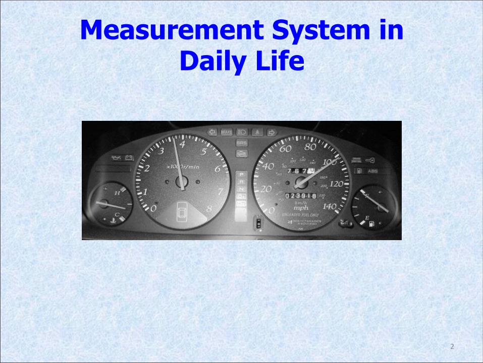
Measurement System in Daily Life
2

3

Measurement System in UCSI
4

5

• PURPOSE: To present an observer with numerical value corresponding to the variable being measured.
6
Purpose and Performance of Measurement
Systems

• The purpose of the measurement system is also to link the observer to the process via the obtained data (in Table 1.1) from the measurement of the process
7

• A process is a system which generates information such as chemical reactor, a jet fighter, a car, a human heart, and a weather system.
• The observer as a person who needs this information from the process such as a car driver, the plant operator or the nurse.
• The input to the measurement system is the true value of the variable; the system output is the measured value of the variable. In reality, the measured value does not equal the true value.
8

• The purpose of the measurement system is to link the observer to the process via the obtained data (in Table 1.1) from the measurement of the process
9

Accuracy of the System • Can be defined as the closeness of the measured value to the
true value.
• A perfectly accurate system is a theoretical ideal.
• The accuracy of a real system is quantified using measurement system error E, where
• Error is the main performance indicator for a measurement system.
• Ex: Measured value of the flow rate of gas in a pipe is 11.0 m3/h and the true value is 11.2 m3/h, then the error E = −0.2 m3/h.
10

• The general measurement system consists of several elements or blocks such as
11
Structure of Measurement Systems


1. Temperature Measurement System
15
Examples of Measurement Systems
Thermocouple

• Thermocouple = A sensor to measure the temperature sensing element; this gives a millivolt output.
• Signal conditioning consists of a circuit to compensate for changes in reference junction temperature, and an amplifier.
• Analogue-to-digital converter = Convert the voltage signal into digital form.
• Computer = Corrects for sensor non-linearity, and the measured value is displayed on a VDU display.
16
Temperature Measurement System
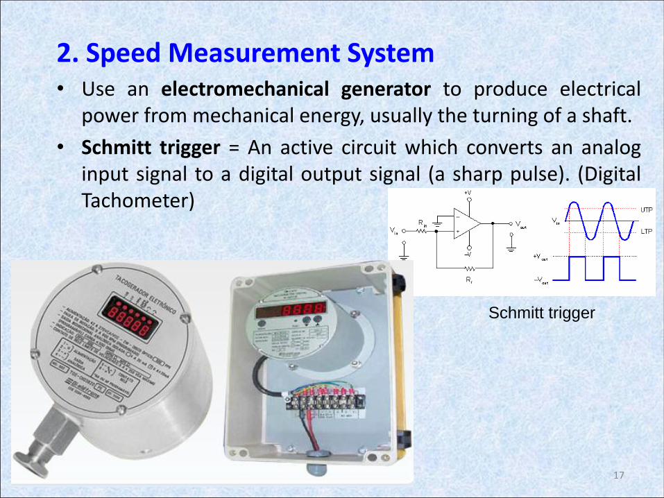
2. Speed Measurement System • Use an electromechanical generator to produce electrical
power from mechanical energy, usually the turning of a shaft.
• Schmitt trigger = An active circuit which converts an analog input signal to a digital output signal (a sharp pulse). (Digital Tachometer)
17
Schmitt trigger

• Electromagnetic Tachogenerator = Sense the speed of rotation of an engine which gives an a.c. output signal with frequency proportional to speed.
• The Schmitt trigger = Convert the sine wave into sharp-edged pulses.
• Counter = Count the sharp-edged pulses over a fixed time interval. Then, the digital count is transferred to a computer.
• Computer = Calculates frequency and speed.
• Digital display = Present the speed in digital form.
18
Speed Measurement System

3. Flow Rate Measurement System
19
Orifice Plate

• Orifice plate sensing element = A device used for measuring flow rate ; this gives a differential pressure output.
• Differential pressure transmitter converts this differential pressure output into a current signal and therefore combines both sensing and signal conditioning stages.
• The ADC converts the current into digital form and
• The computer calculates the flow rate, which is obtained as a permanent record on a chart recorder.
20
Flow Rate Measurement System

4. Weight Measurement System
• Cantilever = Load placement with weight
• Strain Gauge = A device used to measure strain on an object
• Wheatstone Bridge = An electrical circuit used to measure an unknown electrical resistance by balancing two legs of a bridge circuit
21
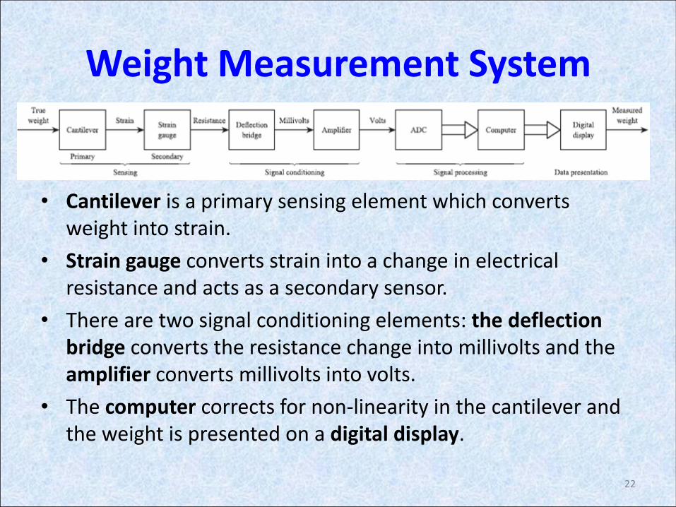
• Cantilever is a primary sensing element which converts weight into strain.
• Strain gauge converts strain into a change in electrical resistance and acts as a secondary sensor.
• There are two signal conditioning elements: the deflection bridge converts the resistance change into millivolts and the amplifier converts millivolts into volts.
• The computer corrects for non-linearity in the cantilever and the weight is presented on a digital display.
22
Weight Measurement System

Wheatstone Bridge •The strain gauge is connected into a Wheatstone Bridge circuit with a combination of four active gauges (full bridge), two gauges (half bridge), or, less commonly, a single gauge (quarter bridge) • As stress is applied to the bonded strain gauge, a resistive changes takes place and unbalances the Wheatstone Bridge. •This results in a signal output, related to the stress value. As the signal value is small, (typically a few millivolts) the signal conditioning electronics provides amplification to increase the signal level to 5 to 10 volts, a suitable level for application to external data collection systems such as recorders or PC Data Acquistion and Analysis Systems.
23

Measurement Applications categories:
1. Monitoring of processes and operations 2. Control of Process and operations 3. Experimental engineering analysis
Applications in Manufacturing
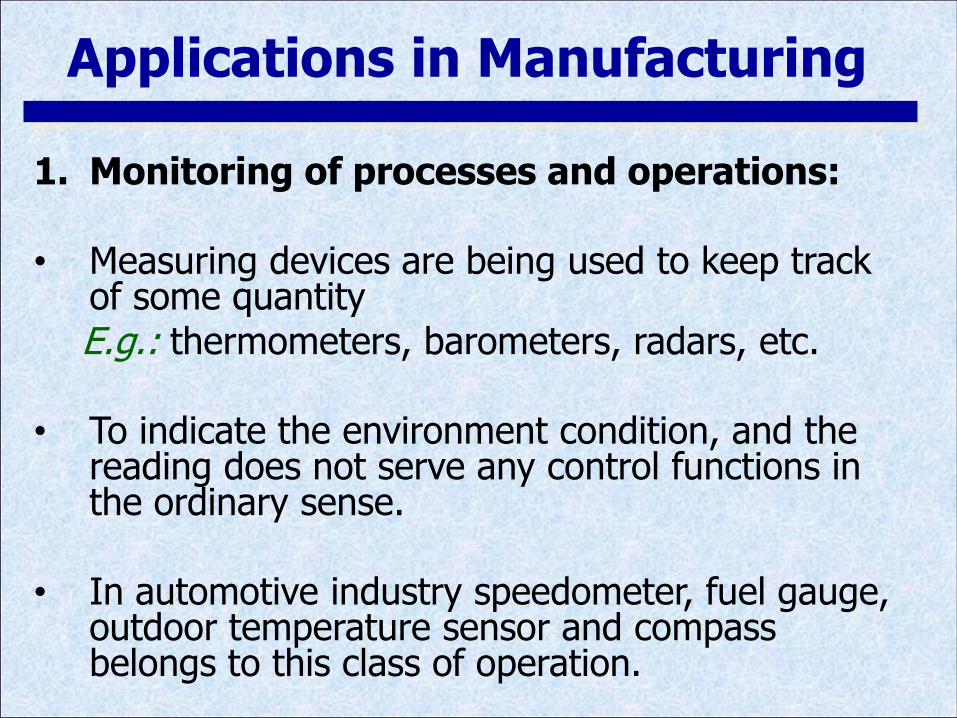
1. Monitoring of processes and operations: • Measuring devices are being used to keep track
of some quantity E.g.: thermometers, barometers, radars, etc.
• To indicate the environment condition, and the reading does not serve any control functions in the ordinary sense.
• In automotive industry speedometer, fuel gauge,
outdoor temperature sensor and compass belongs to this class of operation.
Applications in Manufacturing
2. Control of processes and operation:
• Automatic feedback control systems.
• Sensors are used as feedback systems.
• Every feedback control system have at least one measuring device as a vital component
Applications in Manufacturing

Applications in Manufacturing

3. Experimental Engineering Analysis:
• All the engineering design, development and research lies on laboratory testing
• Solutions
– Theory ~
– Experimentation ~
Applications in Manufacturing

Mohamadariff Othman
FETBE
29
Static Characteristics of
Measurement System Elements
Chapter #01

Characteristics of Measurement System Elements
Discuss on characteristic that typical elements may posses and give effect on the overall performance of the system.
I O Element
- Systematic Characteristics
- Statistical Characteristics
- Generalized Model

Characteristics of Measurement System Elements
Element Characteristics
Static Characteristics
(Steady-state Characteristics)
Dynamic Characteristics
(Transient Characteristics)
Generalized Model
(Block Diagram or Mathematical forms)
Systematic Characteristics
(Graphical or Mathematical forms)
Identification of Static Characteristics
(Statistical Characteristics)
- Range
- Span
- Linear
- Non-Linearity
- Sensitivity
- Hysteresis
- Resolution
- Error Band
- Environmental Effects:
+ Modifying Env. Inputs
+ Interfering Env. Inputs
- Repeatability
- Tolerance
- Calibration:
+ Standards
+ SI Units
+ Experimental: O vs I (Im=Ii=0)
O vs Im, Ii (I=Constant)
Repeatability Test

• Static/Steady-State Characteristic
The relationship between input I (constant value or changing slowly) and output O.
• It has three kind of characteristic:
– Systematic Characteristic = Those can be exactly quantified by mathematical or graphical means
– Statistical Characteristic = Identification of static characteristic.
– Generalized Model = To represent static and dynamic characteristic in term of block diagram and mathematical form.
32
Characteristics of Measurement System Elements
• Dynamic Characteristic
The ways in which an element responds to sudden input changes.
– These are most conveniently summarized using a transfer function G(s).
33
Characteristics of Measurement System Elements