em&cp best management practices environmental and
TRANSCRIPT
EM&CP
Best Management Practices
Environmental and Agricultural Land Protection
November 2012

iii EM&CP Best Management Practices (Nov. 2012) Environmental and Agricultural Land Protection
TABLE OF CONTENTS
INTRODUCTION .................................................................................................................................... 1-1
1.0 EROSION AND SEDIMENT CONTROL PROCEDURES ................................................... 1-1
1.1 CONSTRUCTION SEQUENCING ................................................................................ 1-2 1.2 STRUCTURAL CONTROLS ......................................................................................... 1-3
1.2.1 Stabilized Construction Entrance (see Figure 5A.35 in Exhibit A) .................... 1-3 1.2.2 Silt Fence and Straw Bale Barriers (see Figures 5A.7 and 5A.8 in Exhibit
A) ........................................................................................................................ 1-3 1.2.3 Water-diversion Structures ................................................................................. 1-4 1.2.4 Temporary Access Bridges and Culverts (see Figures 5A.36, 5A.37 and
S14689 in Exhibit A) .......................................................................................... 1-5 1.2.5 Sediment Trap (see Figures 5A.16(1), 5A.16(2), 5A.17, 5A.18, 5A.19,
5A.20(1), 5A.20(2) and 5A.21 in Exhibit A) ...................................................... 1-5 1.2.6 Stone Check Dams (see Figure 5A.9 in Exhibit A) ............................................ 1-5 1.2.7 Level Spreader (see Figure 5A.5 in Exhibit A) .................................................. 1-5 1.2.8 Concrete Washouts (see Figure S14690 in Exhibit A) ....................................... 1-6 1.2.9 Equipment Mats (Mats) (see Figure S14691 in Exhibit A) ............................... 1-6
1.3 DE-WATERING PROCEDURES (SEE FIGURES 5A.23, S14692, S14697-1, S14697-2, S14698, S14700, AND S14703 IN EXHIBIT A) .......................................... 1-6
1.4 DUST CONTROL ........................................................................................................... 1-8 1.5 CLEARING, EXCAVATION, AND GRADING ........................................................... 1-8 1.6 SITE STABILIZATION .................................................................................................. 1-8
1.6.1 Protection of Vegetation Cover .......................................................................... 1-9 1.6.2 Mulching ............................................................................................................. 1-9 1.6.3 Temporary Seeding and Stabilization ................................................................. 1-9
1.7 EROSION CONTROL MAINTENANCE ...................................................................... 1-9 1.8 INSPECTION AND RECORD-KEEPING ................................................................... 1-10 1.9 OPERATIONAL STORMWATER MANAGEMENT ................................................. 1-11
2.0 CLEARING AND SLASH DISPOSAL PROCEDURES ........................................................ 2-1
2.1 DETAILED RIGHT-OF-WAY INVENTORY ............................................................... 2-1 2.2 VEGETATION MANAGEMENT SYSTEM INVENTORY ......................................... 2-1
2.2.1 Management Units and Treatment Method Selection......................................... 2-1 2.3 DEFINITION OF VEGETATION DENSITIES ............................................................. 2-2 2.4 TYPICAL WOODY SPECIES AND COMPATIBILITY WITH CLEARANCE
REQUIREMENTS ........................................................................................................... 2-2 2.4.1 Undesirable Tall Growing Species ..................................................................... 2-2 2.4.2 Tall Shrubs and Small Trees Primarily for the Border Zone .............................. 2-3 2.4.3 Woody Shrubs .................................................................................................... 2-3
2.5 GOALS OF THE RIGHT-OF-WAY MANAGEMENT PLAN ...................................... 2-4 2.5.1 Procedure for Accomplishing the Right-of-Way Management Plan Goals ........ 2-5 2.5.2 Wetlands ............................................................................................................. 2-5
2.6 DESCRIPTION OF VEGETATION MANAGEMENT TECHNIQUES AND CONDITIONS OF USE .................................................................................................. 2-6 2.6.1 Conventional Stem Foliar Technique ................................................................. 2-6

iv EM&CP Best Management Practices (Nov. 2012) Environmental and Agricultural Land Protection
2.6.2 Low Volume Foliar Technique ........................................................................... 2-7 2.6.3 Basal Technique .................................................................................................. 2-7 2.6.4 Cutting and Stump Treatment Technique ........................................................... 2-8 2.6.5 Cutting/Pruning Technique (with no herbicide treatment) ................................. 2-9 2.6.6 Mechanical Mowing Technique ......................................................................... 2-9
2.7 HAZARD TREES .......................................................................................................... 2-10 2.8 SLASH DISPOSAL METHODS .................................................................................. 2-10
2.8.1 General Procedures ........................................................................................... 2-10 2.8.2 Piling ................................................................................................................. 2-11 2.8.3 Chipping ........................................................................................................... 2-11 2.8.4 Drop and Lop .................................................................................................... 2-11
2.9 PROCEDURE FOR HERBICIDE APPLICATION...................................................... 2-12 2.10 PROCEDURE FOR SELECTIVE RETENTION OF SHRUB AND LOW-
GROWING TREE SPECIES ......................................................................................... 2-13 2.11 PROCEDURE FOR MINIMIZING POTENTIAL ADVERSE
ENVIRONMENTAL OR VISUAL IMPACT ............................................................... 2-13 2.12 SCREENS OR BUFFER ZONES ................................................................................. 2-13 2.13 PROCEDURES FOR CLEARING IN HARMONY WITH EXISTING LAND
USE ACTIVITIES ......................................................................................................... 2-14
3.0 STREAM AND WETLAND PROTECTION PROCEDURES .............................................. 3-1
3.1 STREAMS, WETLANDS, AND OTHER WATER RESOURCE PROTECTION ....... 3-1 3.2 TYPICAL STANDARDS AND PROCEDURES FOR WETLAND, WETLAND
ADJACENT AREA, AND WATER RESOURCE PROTECTION................................ 3-1 3.2.1 Stream and Watercourse Protection .................................................................... 3-4 3.2.2 Wetland Protection ............................................................................................. 3-6
3.3 TREATED WOOD .......................................................................................................... 3-7
4.0 AGRICULTURAL LAND PROTECTION PROCEDURES ................................................. 4-1
4.1 EXISTING AGRICULTURAL LAND IN THE ROW ................................................... 4-1 4.2 CONSTRUCTION PROCEDURES IN AGRICULTURAL LANDS ............................ 4-2
4.2.1 Construction Parking, Staging, and Storage Areas ............................................. 4-2 4.2.2 Vegetation Clearing and Disposal ...................................................................... 4-3 4.2.3 Structure Installation ........................................................................................... 4-3 4.2.4 Backfill and Preliminary Grading ....................................................................... 4-3 4.2.5 Subsurface Drain Tiles ........................................................................................ 4-4 4.2.6 Clean-up and Restoration .................................................................................... 4-4 4.2.7 Re-vegetation in Agricultural Lands ................................................................... 4-6 4.2.8 Agricultural Remediation and Monitoring .......................................................... 4-6
5.0 GENERAL CLEAN-UP AND RESTORATION PROCEDURES ......................................... 5-1
5.1 CLEAN-UP PROCEDURES ........................................................................................... 5-1 5.2 RESTORATION .............................................................................................................. 5-1 5.3 RESTORATION IN NON-AGRICULTURAL AND NON-RESIDENTIAL
AREAS ............................................................................................................................ 5-1 5.3.1 Grading ............................................................................................................... 5-1 5.3.2 Soil Stabilization, Aeration, and Fertilization in Landscaped Areas .................. 5-2 5.3.3 Mulch Application .............................................................................................. 5-3 5.3.4 Groundcover Restoration .................................................................................... 5-4
5.4 RESTORATION IN URBAN/RESIDENTIAL AREAS ................................................ 5-4 5.4.1 Planting Time Periods ......................................................................................... 5-5

v EM&CP Best Management Practices (Nov. 2012) Environmental and Agricultural Land Protection
5.4.2 Plant Inspection, Guarantee, and Maintenance ................................................... 5-5 5.4.3 Restoration of Walls and Fences ........................................................................ 5-5
6.0 ACCESS ROAD TYPES AND DEFINITIONS ....................................................................... 6-1
6.1 CONSTRUCTION ACCESS ROADS ............................................................................ 6-1 6.2 ACCESS TO ROW FROM PUBLIC ROADS ................................................................ 6-1 6.3 MAINTENANCE OF EXISTING ACCESS ROADS AND ROUTES .......................... 6-1 6.4 ACCESS ROAD TYPES ................................................................................................. 6-2
6.4.1 Type 1: Unimproved Access Roads (see Figure S14693 in Exhibit A) ............. 6-2 6.4.2 Type 2: Permanent, Stabilized Access Roads (see Figure S14694 in Exhibit
A) ........................................................................................................................ 6-2 6.4.3 Type 3: Temporary Access Roads (see Figures, S14689, S14691 and
S14695 in Exhibit A) .......................................................................................... 6-2 6.5 ROAD CONSTRUCTION IN WETLANDS .................................................................. 6-3 6.6 MAINTENANCE OF EXISTING CULVERTS & FORDS ........................................... 6-3
7.0 INVASIVE SPECIES CONTROL ............................................................................................ 7-1
7.1 HAZARD IDENTIFICATION ........................................................................................ 7-1 7.2 MEASURES TO PREVENT OR CONTROL THE TRANSPORT OF INVASIVE
PLANT SPECIES ............................................................................................................ 7-1 7.3 WETLANDS AND WATERBODIES ............................................................................ 7-2 7.4 UPLAND INVASIVE PLANT SPECIES ....................................................................... 7-2 7.5 DISPOSAL OF WOOD, PLANT MATERIAL, SOIL, AND DEBRIS .......................... 7-3 7.6 INVASIVE INSECT CONTROL .................................................................................... 7-3 7.7 LIST OF INVASIVE PLANT SPECIES ......................................................................... 7-3
8.0 MEASURES TO PROTECT RARE, THREATENED AND ENDANGERED FLORA AND FAUNA SPECIES AND SIGNIFICANT NATURAL COMMUNITIES ........................................... 8-1
8.1 EXISTING RARE, THREATENED AND ENDANGERED SPECIES IDENTIFICATION ......................................................................................................... 8-1 8.1.1 Known RTE Species ........................................................................................... 8-1 8.1.2 Unanticipated Discovery of RTE Species During Construction ......................... 8-2
8.2 SIGNIFICANT NATURAL COMMUNITIES ............................................................... 8-2
9.0 INSPECTION AND MONITORING ....................................................................................... 9-1
9.1 ENVIRONMENTAL MONITOR ................................................................................... 9-1 9.1.1 Qualifications ...................................................................................................... 9-1 9.1.2 Responsibilities ................................................................................................... 9-1
9.2 CONSTRUCTION INSPECTOR .................................................................................... 9-2 9.2.1 Qualifications ...................................................................................................... 9-2 9.2.2 Responsibilities ................................................................................................... 9-3
9.3 SAFETY INSPECTOR .................................................................................................... 9-3 9.3.1 Qualifications ...................................................................................................... 9-3 9.3.2 Responsibilities ................................................................................................... 9-4
9.4 QUALITY ASSURANCE INSPECTOR ........................................................................ 9-4 9.4.1 Qualifications ...................................................................................................... 9-4 9.4.2 Responsibilities ................................................................................................... 9-5
9.5 AGRICULTURAL INSPECTOR .................................................................................... 9-5 9.5.1 Qualifications ...................................................................................................... 9-5 9.5.2 Responsibilities ................................................................................................... 9-6

vi EM&CP Best Management Practices (Nov. 2012) Environmental and Agricultural Land Protection
10.0 POLLUTION PREVENTION ................................................................................................. 10-1
10.1 POTENTIAL POLLUTANT SOURCES ...................................................................... 10-1 10.2 GOOD HOUSEKEEPING PRACTICES ...................................................................... 10-2
10.2.1 Solid Waste ....................................................................................................... 10-2 10.2.2 Sanitary Waste .................................................................................................. 10-2 10.2.3 Hazardous Waste .............................................................................................. 10-2 10.2.4 Construction Materials ...................................................................................... 10-3 10.2.5 Construction Equipment ................................................................................... 10-3
10.3 SPILL RESPONSE AND CLEANUP PROCEDURES ................................................ 10-4 10.3.1 Notification and Reporting ............................................................................... 10-4 10.3.2 Spill Response Plan .......................................................................................... 10-5 10.3.3 Unanticipated Encounters with Contaminated Soil .......................................... 10-5
11.0 OVERHEAD CONSTRUCTION ............................................................................................ 11-1
11.1 SCOPE OF WORK ........................................................................................................ 11-1 11.1.1 Clearing ............................................................................................................. 11-1 11.1.2 Access Roads .................................................................................................... 11-1 11.1.3 Construction ...................................................................................................... 11-1 11.1.4 Stringing of Conductors .................................................................................... 11-2 11.1.5 Clean up and Restoration .................................................................................. 11-2
11.2 STRUCTURE FABRICATION AND ERECTION ...................................................... 11-2 11.3 STRUCTURE REMOVAL PROCESS ......................................................................... 11-4
11.3.1 Structure Removal ............................................................................................ 11-4
12.0 UNDERGROUND TRANSMISSION LINE CONSTRUCTION ........................................ 12-1
12.1 SCOPE OF WORK ........................................................................................................ 12-1 12.1.1 Trenching .......................................................................................................... 12-1 12.1.2 Manhole and Duct Bank Installation ................................................................ 12-3 12.1.3 Stream Crossing Procedures ............................................................................. 12-5 12.1.4 Wetland Crossing Procedures ........................................................................... 12-8 12.1.5 Horizontal Directional Drilling ......................................................................... 12-9 12.1.6 Blasting ........................................................................................................... 12-10 12.1.7 Pre-construction Studies ................................................................................. 12-11 12.1.8 Monitoring and Inspection .............................................................................. 12-11 12.1.9 Notifications, Time Constraints and Safety Precautions ................................ 12-11
13.0 TRANSPORTATION AND UTILITY CROSSINGS ........................................................... 13-1
13.1 ROAD AND HIGHWAY CROSSINGS ....................................................................... 13-1 13.1.1 State Permits and Local Consultation ............................................................... 13-1 13.1.2 Maintenance and Protection of Traffic ............................................................. 13-1 13.1.3 Signs ................................................................................................................. 13-1 13.1.4 Road Repairs and Restoration ........................................................................... 13-1
13.2 RAIL ROAD CORRIDORS .......................................................................................... 13-2 13.2.1 Occupancy Permits ........................................................................................... 13-2 13.2.2 Crossing Permits ............................................................................................... 13-2
13.3 OTHER UTILITIES ...................................................................................................... 13-2 13.3.1 Overhead Electric Facilities .............................................................................. 13-2 13.3.2 Underground Utility Crossings ......................................................................... 13-3

vii EM&CP Best Management Practices (Nov. 2012) Environmental and Agricultural Land Protection
Exhibit A Figures
1-1 EM&CP Best Management Practices (Nov. 2012) Environmental and Agricultural Land Protection
INTRODUCTION The Environmental Management and Construction Plan (“EM&CP”) Best Management Practices (“BMP”) are intended to provide the typical procedures to be followed in the development of either Rochester Gas and Electric Corporation (“RGE” or “Certificate Holder”) or New York State Electric & Gas Corporation (“NYSEG” or “Certificate Holder”) Article VII transmission line project EM&CPs to ensure environmental protection. However, RGE/NYSEG may employ in the EM&CP it proposes to the New York State Public Service Commission (“Commission”) any other environmental protection or mitigation measure(s) it deems more appropriate for the circumstances, whether or not set forth herein, subject to any law or Certificate Condition that requires otherwise. 1.0 EROSION AND SEDIMENT CONTROL PROCEDURES The purpose of storm water management is to prevent erosion both on the construction site itself and on adjacent undisturbed areas, as well as to prevent environmental degradation and prevent erodible soils from entering wetlands and waterbodies. This generally is accomplished through both stabilization and structural control procedures. Stormwater management also addresses pollution prevention through both the implementation of measures to reduce pollutants in storm water and good housekeeping practices on the construction site. Prior to the commencement of construction activities associated with the upgrade of existing electric transmission lines or the construction of new transmission lines which involve soil disturbances of one acre or more of land, RGE/NYSEG will prepare a Stormwater Pollution Prevention Plan (“SWPPP”), authorized under the New York State Department of Environmental Conservation’s (“NYSDEC”) State Pollution Discharge Elimination System (“SPDES”) General Permit for Stormwater Discharges from Construction Activity (“SPDES GP”) Construction Activity, for purposes of the SPDES GP, is defined as "any clearing, grading, excavation, filling, demolition or stockpiling activities that result in soil disturbance. Clearing activities can include, but are not limited to, logging equipment operation, the cutting and skidding of trees, stump removal, and/or brush root removal. Construction activity does not include routine maintenance that is performed to maintain the original line and grade, hydraulic capacity, or original purpose of a facility." The Certificate Holder will include the SWPPP in the EM&CP for the project which will include site-specific erosion and sediment control measures in accordance with the then-effective New York State Standards and Specifications for Erosion and Sediment Control (“NYSSESC”), and, if applicable, post-construction stormwater management practices designed in conformance with the New York State Stormwater Management Design Manual (“NYSSMDM”). The EM&CP Plan and Profile (“P&P”) drawings will show all areas of likely soil disturbance and illustrate and prescribe the location and details of the soil erosion and sediment control measures to be implemented during construction, and post-construction stormwater management practices for permanent access roads, substations, etc., as prescribed in the SWPPP. The following sections describe erosion and sediment control measures conforming to the NYSSESC that are typically used during transmission line construction.
1-2 EM&CP Best Management Practices (Nov. 2012) Environmental and Agricultural Land Protection
1.1 CONSTRUCTION SEQUENCING Proper sequencing and coordination of construction activities represents a key element in minimizing soil disturbance and implementing erosion and sediment control measures in an effective manner. When constructing a new or rebuilding an existing transmission line, construction activities proceed in logical steps and generally involve the following major phases: staking and right-of-way (“ROW”) delineation, clearing and mowing of work spaces and access routes, ROW vegetation management and hazard-tree-related clearing, access road preparation, structure erection, removal, and/or replacement, modification of structures to be retained, wire-pulling operations with specialized work crews, and restoration. A more detailed breakdown and typical sequence of activities to be carried out during transmission line construction or reconstruction is as follows:
a) Staking and flagging/marking construction limits (e.g., ROW, off- and on-ROW access roads, and extra work areas);
b) Marking out of utilities; c) Installation of erosion- and sediment-control measures; d) ROW Clearing, mowing of work spaces and access routes, hazard tree removal and pruning; e) Preparation of access routes and work space areas; f) Delivery of materials; g) Excavation and foundation work in connection with structure removal and replacement and
underground conduit installation; h) Setting structures and fabrication and installation of above-ground structure components (i.e.,
cross arms, insulators, and other hardware), including modification of existing structures; i) Conductor-pulling (overhead circuits); j) Structure removal, if required; k) Restoration of structure site and ROW; and l) Conducting of inspections and maintenance of records.
Representative construction activities for substations generally consist of the following:
a) Work zone clearing (as necessary); b) Install erosion and sediment control measures; c) Stake-out reference point and benchmarks; d) Site grading and installation of permanent water quantity/quality control measures; e) Excavate and install conduits and ground system; f) Foundation construction; g) Erect substation structures; h) Landscaping (e.g., crushed stone topping); i) Stabilize areas disturbed by construction; j) Remove temporary erosion and sediment controls; and k) Inspection and record maintenance.
Devices for erosion and sediment control are installed early in the construction process and implemented at a given location prior to starting any activities at that location that may cause soil disturbances, such as before the start of clearing, grading and excavation activities. Early controls typically include the installation of stabilized construction entrances at locations not previously paved or graveled and the installation of erosion and sediment control measures such as silt fence to prevent stormwater runoff from reaching adjacent properties or sensitive receptors.
1-3 EM&CP Best Management Practices (Nov. 2012) Environmental and Agricultural Land Protection
On completion of the construction activities, all disturbed areas will be stabilized in accordance with the NYSSESC, the SPDES General Permit and the SWPPP. The following sections describe the general erosion controls to be implemented during the construction of the Project. Applicable figures from the NYSSESC, other structural-control typicals, and typicals of other relevant Project-related features are included in Exhibit A. Narrative descriptions of general controls are provided as follows. 1.2 STRUCTURAL CONTROLS Structural controls are used to divert stormwater runoff flows away from disturbed areas, or otherwise limit to the extent possible the discharge of pollutants from exposed areas of the site. Structural controls will be installed prior to the start of work at any structure site within or adjacent to a resource, and will remain in place throughout the construction effort until final restoration and/or landscaping has been established. Routine inspections will be undertaken to ensure that the integrity of these structural controls is maintained. The types of structural controls typically used during transmission line construction are described in the sections below. Specific structural controls will be prescribed on a site-by-site basis during the development of the EM&CP and the SWPPP based on observed site conditions and their locations will be shown on the EM&CP P&P drawings. 1.2.1 Stabilized Construction Entrance (see Figure 5A.35 in Exhibit A) To prevent the deposit of materials onto paved roadways or parking areas, and to prevent runoff from these roadside or parking areas from entering wetlands or streams, stabilized construction entrances will be installed and maintained at all points where construction access roads intersect major highways and roadways. To prevent rutting, typical construction entrances will be covered with a minimum of six (6) inches of #4 stone or larger over filter fabric, unless slope or stability requires different, for a distance of fifty (50) feet into the construction roads prior to site access and disturbance. 1.2.2 Silt Fence and Straw Bale Barriers (see Figures 5A.7 and 5A.8 in Exhibit A) A silt fence consisting of 1” X 1” X 4’ hardwood posts with filter fabric will used as a temporary measure. The silt fence will be installed along the down slope or side slope of a disturbed area. When runoff passes through openings in the fabric, the sediment is trapped by the fabric and settles on the uphill side. Silt fences will be placed, as appropriate, along perimeter areas that drain away from disturbed surfaces. A straw bale barrier acts as a temporary measure in a manner similar to that of a silt fence. Straw (or similar material) bales will be tightly packed in a linear or crenellated fashion, and each bale will be secured with two stakes. Silt fence or straw (or similar material) bale barriers will be provided as follows:
• Along the downhill perimeter edge of all areas disturbed as appropriate; • Along the top of the slope or top bank of drainage ditches, channels, swales, etc. that traverse
disturbed areas; • Along the toe of all cut slopes and fill slopes of the construction areas; • Perpendicular to flow in the bottom of existing drainage ditches, channels, swales, etc., that
traverse disturbed areas or carry runoff from disturbed areas; • Perpendicular to flow in the bottom of new drainage ditches, channels, and swales;

1-4 EM&CP Best Management Practices (Nov. 2012) Environmental and Agricultural Land Protection
• At the entrance to culverts that receive runoff from disturbed areas; • Across the ROW on any slope leading into wetlands or streams; • Along the edge of the construction area with slopes that lead into wetlands or streams; and • On the down slope side of temporary soil piles.
1.2.3 Water-diversion Structures Water-diversion devices will be used to control surface runoff on the ROW and adjacent work areas. For construction activities within the transmission line ROW, water-diversion devices will extend to an undisturbed and stabilized area but not beyond the certified work area. These devices will be installed to direct water away from the construction area but should not extend off the ROW. This will prevent water from returning to the disturbed construction area. The water-diversion devices that may be used during construction include: 1.2.3.1 Waterbars (see Figure 5A.4 in Exhibit A) Waterbars will be used on slopes in the ROW to intercept and divert surface runoff from the work area to a stabilized location. Silt fencing or staked straw bales will be installed at the down-slope outfall to prevent erosion and sedimentation into adjacent off-ROW property. Waterbars will be checked and maintained regularly and, at a minimum, after each major rain event during construction. 1.2.3.2 Driveable Berms Similar in construction to waterbars, these berms may be used temporarily in the ROW access road to divert runoff from entering wetlands from upland roads or work sites. Driveable berms typically are used where straw bales also may be appropriate because using berms eliminates the need for moving straw bales or silt fencing each workday. Driveable berms will be compacted, inspected, and kept in good repair throughout the construction process. This type of berm also can interact with existing erosion- control structures, such as the aforementioned silt fencing and staked straw bales. At all equipment crossings spanning water bodies, only a silt fence, staked straw bale barrier, or equivalent measures will be permitted to prevent sediment from entering the water body. 1.2.3.3 Swales and Earthen Berms (see Figures 5A.1, 5A.2, 5A.3 in Exhibit A) Swales and earthen berms are designed to divert large amounts of runoff that would exceed the capacity of water bar situations. Their size, angle, and spacing depend on the soil type, slope, and other terrain features. They will be used primarily along and at the top of stream banks, at the base of slopes, on steep slopes in excess of twenty-five percent (25%), and wherever conditions warrant a greater measure of runoff control. 1.2.3.4 Side Ditches In areas of severe grade and unstable soils, side ditches adjacent to the ROW may be constructed to channel excess runoff not handled by other drainage structures. On long, steep slopes, periodic breaks and escapes will be constructed to slow runoff velocity and minimize channel erosion. Their spacing will vary according to site conditions and as recommended by the Project Engineer or Environmental Monitor. Side ditches will be maintained regularly to prevent blockage and slumping, particularly after major storm events. Rock or jute-net liner should be considered on steep slopes or severe terrain and in sandy or silty soils to stabilize the ditch.

1-5 EM&CP Best Management Practices (Nov. 2012) Environmental and Agricultural Land Protection
1.2.3.5 French Drains (See Figure S14687 in Exhibit A) A French drain is a stone-filled trench, with or without drain tile. It is used to intercept both surface runoff and subsurface flow, and to firm unstable soils. French drains will be installed where needed for equipment crossings or during restoration under the supervision of the Environmental Monitor and, if applicable, the affected landowner. French-drain construction is similar to diversion-ditch construction except that with the former, geo-textile fabric lines the trench, which then is filled with cobble or stone (six (6) inches or larger). During construction, if it is necessary to cross the French drain with construction equipment, the crossing will be covered with filter fabric and clean fill to prevent clogging with dirt from tires and treads. 1.2.4 Temporary Access Bridges and Culverts (see Figures 5A.36, 5A.37 and S14689 in Exhibit A) Where practicable, temporary bridges will be installed to provide access across a stream or waterway. Temporary mat bridge (figures 5A.36 and S14689) is the preferred bridge type to be utilized. Temporary mat bridges will be used where the span of the crossing can be accomplished with the length of mats available, without compromising the immediate bed or bank of the stream or waterway. Temporary culverts will be installed to channel water runoff from farm ditches and road swales across the ROW, in work areas, and in construction-access areas. They will be installed just below grade at each end, with headwalls, except where used only to equalize drainage in flat areas, such as wetlands. Where the outfall must be above grade, large stone will be placed around the downstream pipe invert to minimize scouring and erosion. Culverts will be sized by calculating flows from the contributing watershed. In some situations, with landowner and agency approval, temporary culverts may be upgraded to permanent installations. 1.2.5 Sediment Trap (see Figures 5A.16(1), 5A.16(2), 5A.17, 5A.18, 5A.19, 5A.20(1), 5A.20(2) and
5A.21 in Exhibit A) Should appropriate runoff control become a concern during high construction-access use, temporary sediment traps will be installed where needed to control heavy runoff near public roads, access roads, streams, wetlands, adjacent land uses, and at construction and equipment sites. Trapped sediment will either be disposed of or graded into upland areas of the ROW. (Please refer to the New York Standards and Specifications for Sediment Traps, pages 5A.35 to 5A.45 including figures 5A.16(1), 5A.16(2), 5A.17, 5A.18, 5A.19, 5A.20(1), 5A.20(2) and 5A.21 in Exhibit A) 1.2.6 Stone Check Dams (see Figure 5A.9 in Exhibit A) A stone check dam is a small dam constructed across a drainage ditch, swale, or channel to lower the speed of concentrated flow to reduce erosion and gully formation and allow sediments and other pollutants to settle out. Stone check dams, which can be either temporary or permanent, will be used where it is otherwise not possible to divert flow and stabilize the channel. The maximum drainage area above a check dam will not exceed two (2) acres. When a given stone check dam no longer is required, it will be removed and the area disturbed will be re-seeded and mulched. 1.2.7 Level Spreader (see Figure 5A.5 in Exhibit A) A level spreader will be installed at the end of each swale and berm to distribute a concentrated discharge to sheet flow and minimize its erosion potential. The outlet area downstream of the level spreader will be stabilized with stone and be of a gradient no steeper than ten (10) percent.

1-6 EM&CP Best Management Practices (Nov. 2012) Environmental and Agricultural Land Protection
1.2.8 Concrete Washouts (see Figure S14690 in Exhibit A) After placement of concrete, wash water used to clean the concrete truck will be directed to a concrete washout structure. Self-installed or pre-fabricated containers may be used to capture the wash water to allow for evaporation or offsite disposal. Washout structures or containers will be inspected after each use to determine if they are filled to seventy-five percent (75%) of capacity and to make sure that the plastic linings are intact and not leaking. Refer to Environmental Protection Agency Best Management Practices for additional information on concrete washout requirements. 1.2.9 Equipment Mats (Mats) (see Figure S14691 in Exhibit A) Mats will be installed in delineated wetland areas and may also be installed at other sensitive areas (e.g., agricultural land) to prevent rutting and other kinds of impact to the soils below. The mats allow for disbursement of the load and the least disturbance to the root zone of existing vegetation. When wooden mats are used, they will be sound, free from decay, and free of vegetative matter, soils, and weed species. 1.3 DE-WATERING PROCEDURES (SEE FIGURES 5A.23, S14692, S14697-1, S14697-2,
S14698, S14700, AND S14703 IN EXHIBIT A) During construction it may be necessary to remove surface or subsurface water from work areas. In relatively minor saturated conditions, where soils consist of consolidated silty loam material and are saturated in static ground water conditions, wet soils will be excavated and stockpiled directly adjacent to the excavation within a circular contained area made from straw bales, silt fence, or both in order to prevent siltation into surrounding areas, wetlands, and waterbodies. In the event that ground water seeps into the excavated hole at a rate not suitable for the above method, but nevertheless is manageable with the use of a portable pump, the discharges of water from the excavation area will be pumped into a filter bag or other sediment trap, as approved by the Environmental Monitor, to settle suspended silt material. In situations where water must be pumped from the excavated hole, the water will be removed, controlled, and discharged using temporary pumps, piping, drainage lines, and ditches in consultation with the Environmental Monitor and according to approved procedures. Pumped water will not be pumped onto gravel fill. Excess soil excavated from the hole will be stockpiled separately within a straw bale/silt fence barrier. Water then will be allowed to infiltrate back into the ground or filter through and/or overtop the straw bale/silt fence dike, depending on the pump rate required. Under extremely saturated conditions where ground water infiltration rates and surrounding water volumes exceed the ability to de-water the excavated hole, a double work-shell arrangement that provides the ability to pump the space between the work-shells and the excavated hole may be necessary. This control arrangement also may be necessary to provide de-watering capability while safely excavating and installing a new structure in incompetent or slumping soils. The straw bale/silt fence barrier described above will be implemented around the structure and the excavated soils. When there is not sufficient room in the work area to install a temporary retention structure as described above, commercial filter bags or an approved sediment tank may be used to remove sediments from de-watered effluent. Once the de-watered effluent passes through the filter bag or sediment tank, the clear water will be allowed to drain onto vegetated areas. Additional erosion and sediment controls will be installed as determined necessary in the field.

1-7 EM&CP Best Management Practices (Nov. 2012) Environmental and Agricultural Land Protection
While in use, pumps employed for de-watering of trenches within one hundred (100) feet of a water body, wetland, or rare plant or unique natural community will be placed in secondary containment devices of the proper size and structure. Trapped sediment collected during de-watering activities will be graded onto the ROW at least one hundred (100) feet from wetlands, streams, and other sensitive resources to prevent sediment transport to these resources. Temporary ditch plugs will be placed in the excavated trench to impede the flow of water down the trench. Hard plugs (unexcavated earth segments of the ditch line) will be maintained adjacent to streams and wetlands to protect those resources until duct bank installation activities occur. Soft plugs (replaced trench spoil, fill, sand bags) will be spaced in the trench in sloping areas to reduce erosion and trench slumping. Hay or straw bales will not be used as material for temporary ditch plugs. After duct bank installation, permanent sand bag trench breakers (see Figure S14700) will be installed and spaced according to industry standard spacing before backfilling. At the discretion of the Construction Manager, hard plugs will be left in place until duct bank installation commences to accommodate equipment crossings. Installation of a small temporary water control structure/cofferdam to isolate and de-water a work area involving less than one hundred (100) cubic yards of temporary fill and less than five thousand (5,000) square feet of working area is authorized, subject to the below-listed conditions. (Associated activities may include the maintenance and repair of existing facilities.)
a) Specifications: Any temporary cofferdam will be constructed of non-erodible materials, so that failure will not occur at two-year (“Q2”) or lower flow conditions. Where practicable, an upstream or interior membrane will be installed to control percolation and erosion. Sandbags will be of the filter fabric type, double-bagged, and individually tied to prevent sand leakage, and only clean sand (i.e., free of debris, silt, fine particles, or other foreign substance) will be used as fill. They will be placed and removed manually to prevent spillage. Straw-bale sediment-control basins are preferred.
b) Fill materials should not come from the waterbody.
c) The water control structure/cofferdam will not impair water flow in the waterbody or water flow into and/or out of a wetland.
d) Excavated or temporarily stockpiled soils or other materials that will be exposed for longer than fourteen (14) days will be temporarily seeded or covered and protected to reduce runoff of fines (which could lead to a turbidity problem) and to prevent rainwater from soaking the materials and rendering them unsuitable for backfill.
e) All temporary water-control structures will be removed in their entirety upon completion of maintenance activity, unless elements of the structure can be converted into habitat- enhancement features, as identified in joint consultation with Staff of the New York Department of Public Service (“DPS Staff” or “Staff”) and NYSDEC and as approved by Staff.
f) Any temporary cofferdam will be constructed of materials that will not contribute to turbidity or siltation in a waterbody. In connection with water being returned to a stream, lake, or wetland
1-8 EM&CP Best Management Practices (Nov. 2012) Environmental and Agricultural Land Protection
from the coffered work area, there will be no discernible difference in water clarity between water upstream and water downstream in that waterbody.
1.4 DUST CONTROL High-traffic areas will be covered with gravel and exposed soils and roadways will be wetted as needed during extended dry periods to minimize dust generation. Only plain water will be used for dust suppression. (Please refer to the New York Standards and Specifications for dust control, pages 5A.87 and 5A.88 provided in Exhibit A.) 1.5 CLEARING, EXCAVATION, AND GRADING In general, the ROW will be cleared to provide safe operation of construction equipment. Typical clearing methods are described in Section 2.6. Access roads and work pads require non-selective clearing (clear-cut) with slash disposal by piling or chipping. ROW-edge clearing typically will use selective clearing, with drop and lop slash disposal in all wetlands and piling or chipping slash disposal in all uplands. Hazard trees will be identified by the procedure outlined in Section 2.7 and be removed by the use of selective clearing methods. Excavated material may be stockpiled temporarily within the ROW, away from stormwater conveyance areas in a manner that prevents erosion and the transport of sediments (e.g., by installing silt fencing). Following backfilling around each pole structure, excess or unsuitable material may be removed from the area to an approved upland disposal location on or off the ROW at least one hundred (100) feet from any wetland or stream, spread evenly, seeded, and mulched in accordance with seed mixes and application rates as prescribed in the Project-specific EM&CP and SWPPP. Removal of excess material from the ROW by the construction contractor (“Contractor”) will only occur upon approval from RGE/NYSEG and DPS Staff. Any old concrete foundations, including those not being utilized, will be removed to at least eighteen (18) inches below ground level (except in agricultural areas, where they will be removed at least forty-eight [48] inches below grade). Any other concrete waste will be removed from the ROW and transported to a concrete salvage facility, if available, or transported to a licensed construction and demolition (“C&D”) disposal facility or solid waste landfill. The Certificate Holder’s construction contractor (“Contractor”) will exercise all necessary and reasonable precautions to minimize sedimentation, soil erosion, and permanent impacts to wetlands and watercourses in the work areas and along the ROW. Special conditions and erosion and sedimentation controls will be prescribed on the P&P drawings. Any excess excavated material to be removed from wetlands, watercourses, or adjacent areas will not be stored in wetlands, streambeds, or adjacent areas. Excavated material will be stockpiled with proper stabilization, erosion controls, and drainage outside the wetland or watercourse, and thereafter disposed of at approved upland locations. 1.6 SITE STABILIZATION In addition to the structural controls described above, stabilization measures that may be used during Project construction also include non-structural controls. Although work sites around pole locations generally are confined to small areas, surface-stabilization techniques will be used during construction to reduce the potential of sediment loading in stormwater runoff from disturbed areas. All disturbed areas that are left exposed more than fourteen (14) days, and not subject to construction traffic, will receive temporary seeding or stabilization in accordance with the NYSSESC. Stabilization procedures should be initiated as soon as practicable, but no more than seven (7) days after construction activities have temporarily or permanently ceased on any portion of the site. If weather (e.g.,

1-9 EM&CP Best Management Practices (Nov. 2012) Environmental and Agricultural Land Protection
snow cover or frozen ground conditions) precludes immediate initiation of stabilization, then such measures will be undertaken as soon as practicable. Where construction activity resumes on a portion of the site within fourteen (14) days from the cessation of activities, then stabilization procedures do not have to be initiated on that portion of the site where the erosion hazard is low (e.g., greater than one hundred [100] feet from streams and wetlands, and where steep grades or adverse soil conditions are absent). Temporary and permanent vegetative cover standards will be in accordance with NYSSESC and incorporated into the EM&CP. If vegetative cover has not reached eighty percent (80%) of the area affected after two growing seasons, a conservation seed mix will be applied to supplement native re-vegetation. The Environmental Monitor may direct additional temporary and/or permanent measures as appropriate to protect natural resources. If excavated or temporarily stockpiled soils or other materials are exposed for longer than fourteen (14) days they will be temporarily seeded or covered and protected to reduce runoff of fines (which may cause turbidity) and to prevent rainwater from soaking the materials and rendering them unsuitable for backfill. Non-structural controls include the following: 1.6.1 Protection of Vegetation Cover Natural vegetation will be preserved to the extent practicable because, where feasible, this will reduce soil erosion. 1.6.2 Mulching Mulching is the placement of material, including, but not limited to, grass (via permanent or temporary seeding), woodchips, straw, or other suitable material including locally grown hay, as appropriate on the soil surface to cover and hold in place disturbed soils. Appropriate seed mixture and feed rates that may be used with mulching certain areas will be prepared as specified in the applicable NYSSESC, and woodchips, except where used for permanent access roads, should be applied at a depth of three (3) inches. Biodegradable rolled erosion-control products may be used across the site and will be used where the grade exceeds a one-foot (1’) rise in a four-foot (4’) horizontal run. The rolled erosion-control product will be nailed, staked, or stapled into the ground per the manufacturer’s installation instructions. Wood chips will not be used as mulch in agricultural lands. 1.6.3 Temporary Seeding and Stabilization Temporary vegetation cover (i.e., seeding) will be used to the maximum extent practicable for areas disturbed for periods longer than fourteen (14) days. Seed mixture rates for the Project will be applied in accordance with the applicable NYSSESC. Embankments and ditches of areas that are left exposed for more than seven (7) days, or are subject to heavy rain before permanent stabilization, will be mulched temporarily with straw and anchored with the mulch binder of the type in, and at the rate specified by, the NYSSESC. 1.7 EROSION CONTROL MAINTENANCE To ensure proper operation of the soil erosion and sediment controls, routine maintenance activities will be conducted along the Project ROW and access roads, as well as at the marshaling yards and other construction sites. These will include, but are not limited to, the following:

1-10 EM&CP Best Management Practices (Nov. 2012) Environmental and Agricultural Land Protection
a) Maintenance of stabilized construction entrances to ensure their proper function.
b) Inspection of all structural controls receiving flows from areas that have not been stabilized permanently will occur at least once each week, twice each week if more than five (5) acres is disturbed at any one time.
c) Inspection of silt fences for depth of sediment, tears, or sags in the fabric, to ensure the fabric
remains adequately dug into the ground, and is attached securely to the posts. Posts will be inspected to ensure that they are firmly set in the ground. In the event that fabric on the silt fence should decompose or become ineffective while the barrier still is necessary, the fabric will be promptly replaced.
d) Removal and subsequent grading into the ROW of built-up sediment from silt fences where
accumulations reach twenty percent (20%) of the above-ground height of the silt fence.
e) Inspection of straw (or suitable material) bale barriers for depth of sediment, broken strings, and barrier integrity. Straw (or suitable material) bale barriers will be replaced when the strings have broken. Two stakes will be maintained in every bale. Firm contact will be maintained between adjacent bales and between the bales and the ground.
f) Removal and subsequent grading into the ROW of built-up sediment where accumulations reach
twenty percent (20%) of the above-ground height of any straw bale barrier.
g) Inspection of each stone check dam to ensure that the center of the dam is lower than the edges. Erosion caused by high flows around the edges of the dam will be corrected immediately. Immediate adjustment of any stone check dam if evidence of siltation in the water is apparent downstream from that dam.
h) Removal and subsequent grading into the ROW, or off-site disposal, of built-up sediment where
accumulations reach twenty percent (20%) of the capacity of the stone check dam.
i) Maintenance of conveyance structures, such as waterbars and diversion ditches, to ensure they operate in design condition. When necessary, velocity-attenuating devices, such as rip rap or other measures, should be used to accomplish the desired result. Foreign debris will not be allowed to accumulate in any swales, drainage ditches, or temporary sediment-retention ponds.
j) Removal of accumulated silt, broken branches, and other debris that interferes with drainage or
sediment collection. 1.8 INSPECTION AND RECORD-KEEPING For construction activities along the transmission line ROW, the Environmental Monitor will perform inspections of all erosion and sediment control measures at least once every seven (7) calendar days in accordance with SPDES GP-0-10-001, or twice every seven (7) calendar days if more than five (5) acres are disturbed. Inspections will be performed on all disturbed areas that have not undergone final stabilization, at all stormwater discharges from the site, on areas used for storage of materials that are exposed to precipitation, on structural control measures, and on vehicle entrances and exits. For areas that have undergone final stabilization, or where runoff is unlikely due to winter conditions, inspections will be performed at least once every month by the Environmental Monitor, and the Certificate Holder will notify DPS and NYSDEC regional staff of any change in the frequency of
1-11 EM&CP Best Management Practices (Nov. 2012) Environmental and Agricultural Land Protection
inspections as required by the SWPPP. Material storage areas and disturbed areas will be inspected for evidence of, or the potential for, pollutants entering the drainage system. Measures implemented with respect to erosion and sediment control will be inspected to ensure that they are operating correctly. Vehicle construction entrances and exits will be inspected for evidence of off-site sediment tracking. Inspection reports will be prepared for each inspection performed and retained along with the Project-specific EM&CP and SWPPP. Each inspection report will provide the name(s), title(s), and qualifications of the personnel conducting the inspection, date(s) of the inspection, a description of the weather and soil conditions, and major observations resulting from the inspection relevant to the implementation of the EM&CP/SWPPP. Observations will include the identification and reporting of the following:
a) Locations, if any, of sediment or other pollutant discharges; b) Locations, if any, requiring maintenance; c) Locations, if any, failing to operate adequately or as designed; d) Locations, if any, where additional procedures are required; e) Corrective action(s) that must be taken to install, repair, replace or maintain erosion and sediment
control practices, and to correct deficiencies identified with the construction of any post-construction stormwater management practice(s);
f) Digital, date-stamped photographs of any sites and/or practices that require corrective action; g) Descriptions of activities, if any, conducted in contravention of the Project-specific
EM&CP/SWPPP or otherwise contributing to stormwater pollution; and h) Anticipated construction activities and the appropriate erosion and sedimentation controls.
The inspection report will identify any incidents of non-compliance and concomitant responses to be implemented. For incidents of non-compliance, the inspection report also will describe the modifications to the Project or control measures to be implemented to prevent further incidents of non-compliance. Inspection reports will be provided to the Contractor, who will be required to begin implementation of any identified corrective actions needed within twenty-four (24) hours of receipt of the inspection report. All required repairs must be completed before the next anticipated storm event. The inspection reports will be maintained at the construction field office during the course of the Project. In addition, the Certificate Holder will retain the inspection reports and EM&CP in the Project files for a period of five (5) years after completing the Project and submitting a Notice of Termination (NOT) to the NYSDEC. 1.9 OPERATIONAL STORMWATER MANAGEMENT The ROWs will be vegetated and maintained by the Certificate Holder in accordance with the Long Range Right-of-Way Management Plan for the NYSEG and RG&E Electric Transmission System (“LRROWMP”). Periodically, culverts that were installed for drainage under access roads or permanent stabilized construction entrances will be inspected and maintained. Typically, there are no permanent stormwater management controls (e.g., detention basins, drainage- conveyance structures like catch basins) installed for the construction of transmission facilities in ROWs. However, should permanent stormwater management controls be required based on site-specific conditions or conditions of the Certificate, their locations should be shown on the P&P drawings and a maintenance schedule provided in the EM&CP document.

2-1 EM&CP Best Management Practices (Nov. 2012) Environmental and Agricultural Land Protection
2.0 CLEARING AND SLASH DISPOSAL PROCEDURES 2.1 DETAILED RIGHT-OF-WAY INVENTORY The Certificate Holder conducts clearing activities for new ROW and for vegetation management of existing ROWs. For new ROW and existing ROW, the Certificate Holder Forester or assigned forestry consultant (either, the “Forester”) conducts a detailed vegetation inventory, determining the method of treatment to be employed on each management unit. All pertinent information concerning the ROW width, special conditions and restrictions will be reviewed by the Forester and factored into the treatment design. The inventory information is recorded in a geographic information system (“GIS”)-based vegetation management system (“VMS”) that ties all of the information to a map location. 2.2 VEGETATION MANAGEMENT SYSTEM INVENTORY The purpose of the VMS inventory is to collect and analyze ROW management unit data to prepare a VMS Treatment Plan to be included in the EM&CP for the proposed or existing transmission line facility. An Environmental Monitor will flag all sensitive areas (e.g., protected streams, wetlands, adjacent areas, rare, threatened, and endangered species locations/habitat) before clearing begins. 2.2.1 Management Units and Treatment Method Selection During the VMS inventory, each management unit’s characteristics are entered in a GIS-based VMS system. During the VMS inventory the ROW is divided into management units. A management unit is a segment of ROW, shown as a polygon on the VMS map, with similar site conditions such as vegetation and land use, which can be treated using the same management technique. When a change in site condition warrants a change in the management technique, a new management unit is designated. Management units are assigned a unique identification number. Each management unit is described in terms of land use, height and density of incompatible vegetation, density of compatible vegetation, ROW restrictions, special instructions, and prescribed treatment. The area in acres is recorded. When selecting a treatment technique, many factors are evaluated and their relative importance considered. These factors include:
1. Height, density, and composition of undesirable vegetation 2. Susceptibility of undesirable vegetation to treatment techniques 3. Density and composition of desirable vegetation 4. Specific site conditions such as:
a. Land use b. Presence of waterbodies c. Presence of sensitive crops d. Accessibility e. Visual sensitivity f. Soil sensitivity
5. Relative costs of using various techniques on the specific site 6. Past management activities 7. Conditions subject to governmental regulation 8. Easement restrictions
2-2 EM&CP Best Management Practices (Nov. 2012) Environmental and Agricultural Land Protection
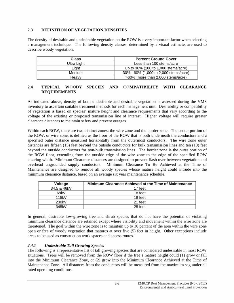
2.3 DEFINITION OF VEGETATION DENSITIES The density of desirable and undesirable vegetation on the ROW is a very important factor when selecting a management technique. The following density classes, determined by a visual estimate, are used to describe woody vegetation:
Class Percent Ground Cover Ultra Light Less than 100 stems/acre
Light Up to 30% (100 to 1,000 stems/acre) Medium 30% - 60% (1,000 to 2,000 stems/acre) Heavy >60% (more than 2,000 stems/acre)
2.4 TYPICAL WOODY SPECIES AND COMPATIBILITY WITH CLEARANCE
REQUIREMENTS As indicated above, density of both undesirable and desirable vegetation is assessed during the VMS inventory to ascertain suitable treatment methods for each management unit. Desirability or compatibility of vegetation is based on species’ mature height and clearance requirements that vary according to the voltage of the existing or proposed transmission line of interest. Higher voltage will require greater clearance distances to maintain safety and prevent outages. Within each ROW, there are two distinct zones: the wire zone and the border zone. The center portion of the ROW, or wire zone, is defined as the floor of the ROW that is both underneath the conductors and a specified outer distance measured horizontally from the outermost conductors. The wire zone outer distances are fifteen (15) feet beyond the outside conductors for bulk transmission lines and ten (10) feet beyond the outside conductors for non-bulk transmission lines. The border zone is the outer portion of the ROW floor, extending from the outside edge of the wire zone to the edge of the specified ROW clearing width. Minimum Clearance distances are designed to prevent flash over between vegetation and overhead ungrounded supply conductors. Minimum Clearance To Be Achieved at the Time of Maintenance are designed to remove all woody species whose mature height could intrude into the minimum clearance distance, based on an average six year maintenance schedule.
Voltage Minimum Clearance Achieved at the Time of Maintenance 34.5 & 46kV 17 feet
69kV 18 feet 115kV 18 feet 230kV 21 feet 345kV 25 feet
In general, desirable low-growing tree and shrub species that do not have the potential of violating minimum clearance distance are retained except where visibility and movement within the wire zone are threatened. The goal within the wire zone is to maintain up to 30 percent of the area within the wire zone open or free of woody vegetation that matures at over five (5) feet in height. Other exceptions include areas to be used as construction work spaces and access routes. 2.4.1 Undesirable Tall Growing Species The following is a representative list of tall growing species that are considered undesirable in most ROW situations. Trees will be removed from the ROW floor if the tree’s mature height could (1) grow or fall into the Minimum Clearance Zone, or (2) grow into the Minimum Clearance Achieved at the Time of Maintenance Zone. All distances from the conductors will be measured from the maximum sag under all rated operating conditions.

2-3 EM&CP Best Management Practices (Nov. 2012) Environmental and Agricultural Land Protection
Ash Hemlock Aspen, Cottonwood Hickory Basswood Hophornbeam Beech Maple Birch Mountain Ash Black Gum/Tupelo Oak Locust* Pine Black Walnut Red Mulberry Butternut Sassafras Catalpa Spruce Cedar Sycamore Cherry Tamarack/Larch Chestnut Tree of Heaven* Cucumber Tree Tulip/Yellow Poplar Elm Willow Fir
2.4.2 Tall Shrubs and Small Trees Primarily for the Border Zone The following is a representative list of tall shrubs and small trees that may be compatible in the border zone, except on narrower sub-transmission ROWs. Since these species generally mature at a height of greater than ten (10) feet, they will be removed from anywhere on the ROW floor if their mature height could (1) grow or fall into the Minimum Clearance Zone, or (2) grow into the Minimum Clearance Achieved At the Time of Maintenance Zone. All distances from the conductors will be measured from the maximum sag under all rated operating conditions. These tall shrub and smaller tree species may be preferred for retention in buffer areas and other sensitive sites over taller-growing tree species.
American Hornbeam Red Cedar Apple Scrub Oak Autumn Olive* Shadbush Buckthorn* Shrub Willow Choke Cherry Speckled Alder Common Pear Striped Maple Flowering Dogwood Sumac Hawthorn Witchhazel Hercules Club Witherod Nannyberry * listed as Invasive Species and historically managed as desirable ROW vegetation However, if they need to be cut they should be stump treated to prevent regeneration when appropriate and practicable.
2.4.3 Woody Shrubs The following is a list of shrub species commonly found along ROWs across the service territory. These shrubs generally mature at a height of ten feet or less. While they are nearly always compatible in the
2-4 EM&CP Best Management Practices (Nov. 2012) Environmental and Agricultural Land Protection
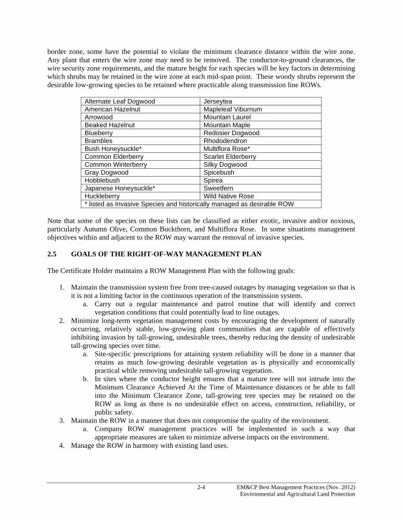
border zone, some have the potential to violate the minimum clearance distance within the wire zone. Any plant that enters the wire zone may need to be removed. The conductor-to-ground clearances, the wire security zone requirements, and the mature height for each species will be key factors in determining which shrubs may be retained in the wire zone at each mid-span point. These woody shrubs represent the desirable low-growing species to be retained where practicable along transmission line ROWs.
Alternate Leaf Dogwood Jerseytea American Hazelnut Mapleleaf Viburnum Arrowood Mountain Laurel Beaked Hazelnut Mountain Maple Blueberry Redosier Dogwood Brambles Rhododendron Bush Honeysuckle* Multiflora Rose* Common Elderberry Scarlet Elderberry Common Winterberry Silky Dogwood Gray Dogwood Spicebush Hobblebush Spirea Japanese Honeysuckle* Sweetfern Huckleberry Wild Native Rose * listed as Invasive Species and historically managed as desirable ROW
Note that some of the species on these lists can be classified as either exotic, invasive and/or noxious, particularly Autumn Olive, Common Buckthorn, and Multiflora Rose. In some situations management objectives within and adjacent to the ROW may warrant the removal of invasive species. 2.5 GOALS OF THE RIGHT-OF-WAY MANAGEMENT PLAN The Certificate Holder maintains a ROW Management Plan with the following goals:
1. Maintain the transmission system free from tree-caused outages by managing vegetation so that is it is not a limiting factor in the continuous operation of the transmission system.
a. Carry out a regular maintenance and patrol routine that will identify and correct vegetation conditions that could potentially lead to line outages.
2. Minimize long-term vegetation management costs by encouraging the development of naturally occurring, relatively stable, low-growing plant communities that are capable of effectively inhibiting invasion by tall-growing, undesirable trees, thereby reducing the density of undesirable tall-growing species over time.
a. Site-specific prescriptions for attaining system reliability will be done in a manner that retains as much low-growing desirable vegetation as is physically and economically practical while removing undesirable tall-growing vegetation.
b. In sites where the conductor height ensures that a mature tree will not intrude into the Minimum Clearance Achieved At the Time of Maintenance distances or be able to fall into the Minimum Clearance Zone, tall-growing tree species may be retained on the ROW as long as there is no undesirable effect on access, construction, reliability, or public safety.
3. Maintain the ROW in a manner that does not compromise the quality of the environment. a. Company ROW management practices will be implemented in such a way that
appropriate measures are taken to minimize adverse impacts on the environment. 4. Manage the ROW in harmony with existing land uses.

2-5 EM&CP Best Management Practices (Nov. 2012) Environmental and Agricultural Land Protection
a. The vegetation management program will recognize and permit multiple uses of ROWs which are compatible with the reliable and safe operation of the transmission facilities and which allow for full compliance with all regulatory requirements.
5. Minimize long-term vegetation management costs by selecting the most economical, site-specific vegetation management techniques that will meet all other goals.
Minimize herbicide use by prescribing herbicides and methods of application that will effectively control undesirable species, maximizing retention of desirable species and also minimizing herbicide usage during future treatments. 2.5.1 Procedure for Accomplishing the Right-of-Way Management Plan Goals The Certificate Holder recognizes and considers the use of manual, mechanical, and/or chemical clearing methods and three (3) slash disposal methods to accomplish its ROW clearing and management goals. Utilizing the potential combinations of these clearing and disposal methods, the Certificate Holder conducts a detailed site-by-site analysis of the ROW to select the appropriate management technique for each management unit. The EM&CP will include a set of detailed drawings which show the location and extent of prescribed clearing for each area of the ROW. All clearing and slash disposal procedures will comply with the Invasive Species Control procedures included in Section 7. 2.5.2 Wetlands Vegetation-clearing on ROWs within waterbodies, or wetlands, will be conducted as follows:
a) For construction activities within state-regulated wetlands and wetland adjacent areas, and within other wetlands and aquatic resources, the Certificate Holder will remove only the minimum vegetation necessary to allow proper installation.
b) For vegetation-management activities to ensure adequacy of transmission line clearance distances, both clear-cutting of undesirable or non-compatible vegetation in wetlands and wetland adjacent areas, and cutting -- but not the elimination or destruction -- of vegetation in wetlands and wetland adjacent areas are allowed. Cutting of tall-growing tree species which could interfere with transmission lines in wetlands and wetland adjacent areas is allowed.
c) Where maintenance or “hazard tree” clearing is required to prevent inadvertent outages, selective
vegetation-clearing techniques within state-regulated wetlands and wetland adjacent areas, and within other wetlands and aquatic resources, is allowed. Cutting of tall-growing tree species which could interfere with transmission lines in wetlands and wetland adjacent areas is allowed pursuant to these selective clearing techniques. Low-growing tree species, shrub species, and herbaceous plants should remain.
d) In wetlands, slash that is cut may be left in place (Drop and Lop). Any slash that is not left in
place must be removed from the wetland. No slash will be collected and permanently piled in the wetland, whether adjacent to an access road or not. Slash may be used for temporary corduroy road for clearing and construction equipment in place of matting but must be removed from the wetland upon completion of construction activities.
2-6 EM&CP Best Management Practices (Nov. 2012) Environmental and Agricultural Land Protection
2.6 DESCRIPTION OF VEGETATION MANAGEMENT TECHNIQUES AND CONDITIONS OF USE
Each technique typically used during vegetation management activities is described below, along with the ROW conditions for which that technique will typically be prescribed. The Forester will utilize their professional judgment to assess site conditions and select the most appropriate technique. Herbicide formulations that are utilized with the various techniques are discussed below in Section 2.9. 2.6.1 Conventional Stem Foliar Technique Using this technique, the entire stem and foliage of the target plant is thoroughly wetted to the point of run-off. The spray formulation is normally made up of a systemic herbicide in a water carrier. The herbicide enters the target plant primarily through absorption and translocates throughout the plant. Stem foliar sprays are applied during the growing season, after full leaf development and before dormancy begins. Stem foliar spraying that employs the proper herbicide formulation can be very effective in obtaining root kill, especially of root suckering species. Stem foliar sprays are normally applied with hydraulic sprayers, equipped with 200 to 500 gallon tanks and two spray guns attached to hoses that are at least 100 feet long. Sprayers are mounted on four-wheel-drive (“4WD”) or on all-terrain vehicles. Water is supplied to the spray vehicle with a 500 to 1000 gallon supply truck. The supply truck is not used for mixing or for transporting chemicals which ensures that sources of water used for spray operations will not be contaminated with herbicide. Stem foliar spray volumes normally range between 75 and 150 gallons of formula per acre. Over-spray is minimized by spraying at the lowest effective pressure from a distance no more than ten (10) feet from the target plant, by limiting applications to sites where the average height of undesirables is fifteen (15) feet or less, and by adding a drift control agent to the spray formulation. Some foliar spray formulations have the advantage of being selective in that they do not kill narrow-leaved herbaceous plants. The method is an efficient, economical technique for treating dense concentrations of undesirable vegetation. The stem foliar technique is utilized where brown-out of the vegetation is not a concern, and where:
• Densities of undesirable species are medium to heavy. • Densities of undesirable species are light to medium, while desirable specie densities are scattered
to light. This will result in smaller quantities of desirable vegetation being affected when utilizing the conventional stem-foliar technique.
• Undesirable species are primarily root-suckering types which are most effectively controlled by foliar-applied techniques.
In addition, the following sites are not treated with the conventional stem foliar technique:
• Within fifty (50) feet of any stream, wetland, or waterbody, or within one hundred (100) feet of a state-regulated wetland, or where specifically instructed by the Certificate Holder
• Within one hundred (100) feet of a potable water supply • Within any orchard, nursery, or crop planting • Within ten (10) feet of a fence which encloses an active pasture • Within any area restricted by the herbicide label • Any other special site identified by the Forester
2-7 EM&CP Best Management Practices (Nov. 2012) Environmental and Agricultural Land Protection
2.6.2 Low Volume Foliar Technique Using this technique, a concentrated waterborne herbicide formulation is applied in a uniform pattern to the top and leads on all sides of the target plant. Coverage must be uniform so that most leaves are treated but not to the point of run-off. The herbicide enters the tree through the foliage and translocates throughout the plant. Low volume foliar sprays are applied during the growing season, after full leaf development, and before dormancy begins. Low volume foliar sprays are applied with a pump-up back-pack sprayer or with a motorized back-pack sprayer. Sprayers are equipped with at least two types of nozzles for treatment of trees of different heights. Low volume foliar spray volumes normally range between five (5) and ten (10) gallons of formulation per acre. Because of the low volume of spray that is applied, and the low pressure provided by the back-pack sprayer, this method can be very selective. This technique requires a less precise application than selective basal sprays, allowing for greater production while at the same time giving the applicator the ability to be selective. This technique is an ideal method for treating undesirable vegetation up to eight (8) feet in height that is light to medium in density. Occasionally the technique is also used on taller target plants up to twelve (12) feet in height, so long as the applicator is prudent in avoiding over spray. The low volume stem foliar technique is utilized where brown-out of vegetation is not a concern. In addition, the following sites will not be treated with the low volume stem foliar technique:
• Within fifteen (15) feet of any stream, wetland, or waterbody, or within one hundred (100) feet of a state-regulated wetland, or where specifically instructed by the Forester
• Within one hundred (100) feet of a potable water supply • Within any orchard, nursery, or crop planting • Within active pastures unless the herbicide label specifically allows for this, and the property
owner or farm operator approves of the application • Within any area restricted by the herbicide label • Any other special site identified by the Forester
2.6.3 Basal Technique Using this technique, the lower twelve (12) to eighteen (18) inches of the stem of each target plant is thoroughly wetted with an oil-borne herbicide formulation. The purpose of the oil carrier is to facilitate bark penetration to carry the herbicide into the tree’s system. To be effective, it is imperative that the treatment completely encircle the stem, and wet the root crown area and all exposed roots. Basal spraying is effective when applied at any time of the year, as long as snow or ice does not prevent spraying to the ground line. Since only the bottom twelve (12) to eighteen (18) inches of each stem is treated and coarse sprays are used, this technique can be very selective with little chance of drift. The technique can also be very effective in achieving root-kill, except for several species that commonly root sucker after being top-killed. When performed during the dormant season, brown-out can be greatly reduced. Hand-powered back-pack sprayers are used to apply the formulations. A wand or extension is attached to the spray gun, delivering the spray pattern directly to the target area and minimizing the size of the spray pattern. Historically, basal spraying has been more expensive than stem foliar spraying due to more intense labor requirements.

2-8 EM&CP Best Management Practices (Nov. 2012) Environmental and Agricultural Land Protection
The selective basal spray technique is utilized where:
• Densities of the undesirable species are light • Densities of the undesirable species are light to medium, while the desirable densities are either
light to medium or medium to heavy • Brown-out of the vegetation that would result from selective foliar sprays would be objectionable. • The ROW agreement restricts the use of foliar techniques • Target vegetation is in a pasture and must be treated during the dormant season when livestock is
not present • The site to be treated is inaccessible during the growing season due to the presence of crops and
must be treated during the dormant season • The target vegetation is located in a hedgerow or other area that is too close to sensitive crops to
utilize a foliar technique • Vegetation densities meet the criteria for foliar techniques, but the average height of the
undesirable species is greater than fifteen (15) feet In addition, the following sites will not be treated with the selective basal technique:
• Within fifteen (15) feet of any stream, wetland, or waterbody, or within one hundred (100) feet of a state-regulated wetland, or where specifically instructed by the Forester
• Within one hundred (100) feet of a potable water supply • Within any orchard, nursery, or crop planting • Within active pastures • Within any area restricted by the herbicide label • Any other special site identified by the Forester
2.6.4 Cutting and Stump Treatment Technique Using this technique, individual stems are cut and the resulting stumps and root collars are treated with an herbicide to prevent re-sprouting. Cutting is usually performed with a chainsaw or a brush saw. An oil-borne herbicide is applied to wet the outer perimeter of the stump, the bark, and all exposed roots. Water-borne formulations are applied only to the cambium of the cut surface. The application equipment for oil-borne formulations is the same as for the basal technique, described in the previous section. For water-borne applications, a hand held squirt bottle is used. Stump treatment prevents the emergence of dormant buds from the stump and the root collar; however stump treatment does not normally prevent root-suckering species from sprouting from dormant buds located along the root system. Vegetation that is cut using this technique is disposed of using several methods, depending on the sensitivity of the site. Disposal methods are discussed below in Section 2.8. Due to the additional labor required for cutting the vegetation, this technique is more costly than the basal technique. The cutting and stump treatment technique is utilized where:
• Standing dead stems would be objectionable due to aesthetic concerns • Clearance concerns exist where cutting is required to address the concern (i.e., the retention of tall
treated stems that result from using one of the other methods would not leave adequate clearance) • The ROW agreement requires that cut vegetation is to be removed • The presence of foliage that is potentially toxic to livestock requires that the vegetation either be
cut during the dormant season, or cut and removed during the growing season
2-9 EM&CP Best Management Practices (Nov. 2012) Environmental and Agricultural Land Protection
• Vegetation to be removed is too tall to foliar spray (greater than fifteen feet [>15 ft] tall) and density is too high for cost effective basal spraying
In addition, the cutting and stump treatment technique will not be used on the following sites:
• Within five (5) feet of any stream, wetland, or waterbody, or within one hundred (100) feet of a state-regulated wetland, or where specifically instructed by the Forester
• Within one hundred (100) feet of a potable water supply • Within any orchard, nursery, or crop planting • Within active pastures unless the herbicide label specifically allows for this, and the property
owner or farm operator approves of the application • Within any area restricted by the herbicide label • Any other special site identified by the Forester
2.6.5 Cutting/Pruning Technique (with no herbicide treatment) Using this technique, undesirable vegetation is either cut down or partially removed by pruning those portions of the tree that are capable of intruding into the Minimum Clearance Achieved at the Time of Maintenance. Pruning is normally performed by using the drop-crotch or natural trimming technique where the limbs to be removed are cut back to the next lateral limb. The tree crews either manually climb the tree or utilize aerial lifts. Cut vegetation is disposed of using one of the slash disposal methods described below. Cutting and pruning are labor intensive techniques, and to control re-growth, they must be repeated on shorter rotations than techniques using herbicides. Hence this technique is less cost effective than techniques employing herbicides. The cutting/pruning technique is utilized where:
• The undesirable vegetation is located in a sensitive area such as residential lawn, park, etc. However, for 69kV and above lines, unless there is an easement restriction, there will be no pruning of target vegetation that is rooted within the specified ROW clearing width. Said vegetation must be removed.
• The ROW agreement restricts the use of herbicides • Certificate Holder specifications restrict the use of herbicides • Side encroachment exists on a site where the ROW agreement will not allow for the total removal
of the targeted vegetation All pruning is done in accordance with American National Standards Institute (“ANSI”) A-300 arboricultural standards. 2.6.6 Mechanical Mowing Technique Using this technique, the vegetation is cut with a large mowing machine attached to an all-terrain vehicle. The cutting swath is normally about eight (8) feet wide, making the technique relatively non-selective. Where the terrain allows for the use of this equipment, mechanical mowing is more cost-effective than hand cutting. If herbicides are not used in conjunction with mechanical mowing, the resulting regrowth will necessitate a short rotation, increasing the cost of using this technique compared to using other techniques that employ herbicides. Mechanical mowing is utilized where the terrain is accessible to mowing equipment and:

2-10 EM&CP Best Management Practices (Nov. 2012) Environmental and Agricultural Land Protection
• The use of herbicides is restricted, and the acreage is large enough to make the use of a mowing machine economically feasible
• The density of the target vegetation meets the same criteria as the conventional stem foliar technique; however the average height of the target vegetation is over fifteen (15) feet. Under these conditions, mechanical mowing would be followed up where possible either by a stem foliar application after re-sprouting has occurred, or by using a mower that also applies herbicide to the cut surface of the mowed stubble.
2.7 HAZARD TREES Hazard trees are located outside of the specified clearing width of the ROW. These trees pose a threat to the reliability of the line. In order to threaten the line, the tree must be sufficiently tall to strike the line if it falls and it must exhibit one or more of the following characteristics that would make it likely to fall:
• The tree displays excessive lean toward the line • The tree is diseased or has a defect that increases the risk that it will fall toward or into the
conductors • The root system is shallow due to moisture conditions or species characteristics, making wind
throw a concern Certificate Holder experience has shown that individual hazard trees are difficult to identify. Often trees that fall into the ROW that strike the conductors exhibit no outward characteristics that would have identified them as a hazard tree prior to the event. In other instances, a large tree located far outside the ROW (more than ten [10] feet) will fall and start a chain reaction that results in an otherwise sound or healthy tree along the edge being pushed into the conductors. The hazard tree program starts at the time a line is built by clearing a ROW to a standard width that provides reasonable protections. The wider the ROW initially cleared, the lower the probability that a tree falling into the ROW will hit the conductors. The Certificate Holder has an ongoing effort to widen existing narrow ROWs, either to the standard width or to the maximum allowed by the applicable easement, whichever is less. Standard ROW widths are as follows:
Voltage Standard ROW Width 34.5kV to 69kV 100 feet
115kV single pole construction 100 feet 115kV H-frame / steel tower construction 125 feet
230kV H-frame construction 150 feet 345kV H-frame construction 175 feet
As far as practical, all hazard trees will be removed at the time of initial clearing and as part of the normal clearing activities. The slash from these hazard trees will be disposed of in accordance with the slash disposal method designated for the section of ROW adjoining the area from which the hazard trees have been removed. 2.8 SLASH DISPOSAL METHODS 2.8.1 General Procedures Cut vegetation will not be disposed of in the following locations:
• Access roads

2-11 EM&CP Best Management Practices (Nov. 2012) Environmental and Agricultural Land Protection
• Within twenty-five (25) feet of a structure • In streams, wetlands (unless the Drop and Lop slash disposal method is specified), or flood prone
areas • In aesthetic or riparian buffer zones • In agricultural fields • In areas maintained as lawns
Vegetation cut from scattered areas, fencerows, or isolated trees in cultivated areas will be removed and placed along the nearest fence line or accepted area for piling. Toxic vegetation will be disposed of outside of active pasture areas. This includes all cherry species as they present a hazard to cattle and maple species that present a hazard to horses. In those locations where vegetation is cut and no method of disposal is specified, the Lop and Scatter method of disposal will be utilized as described below. 2.8.2 Piling Where cut vegetation is to be piled, the piles will have a maximum height of three (3) feet and a maximum width of fifteen (15) feet. The piles will have a twenty (20)-foot break every one hundred (100) feet of pile length to serve as a fire break. Piles will have a neat and orderly appearance, void of any excessive protruding material. Piling with equipment will be performed in accordance with the following:
• Cut vegetation will be carried or dragged, not pushed, to pile locations. • Piles will be compacted to less than the specified maximum height by traversing with tracked
vehicles and/or other equipment. Where cut vegetation is piled by hand, the pile will be compacted to less than the specified maximum height by cutting with chainsaws. Piling of slash will not occur within state-regulated wetlands. 2.8.3 Chipping Where cut vegetation will be reduced to chips by the use of an approved chipping machine in accordance with the following:
• Chips will be disposed of such that chips accumulate to depths no greater than three (3) inches. • No chips will be stored or disposed of in wetlands, active agricultural fields, or in close proximity
(typically not within twenty-five [25] feet) of streams or drainages). 2.8.4 Drop and Lop Trees to be removed will be felled, de-limbed of all branches greater than two (2) inches in diameter, and cut into sections such that the entire length of each tree is in close contact with the ground. Vegetation disposed of in this manner will not protrude more than two (2) feet above the surface of the ground. Where an access road exists, cut vegetation will not be disposed of within the access road. Where no access road exists, a twenty (20) foot swath, directly under the conductors, will remain clear of cut vegetation. Drop and Lop slash disposal methods will only be used where the accumulation of slash is sufficiently removed from public view to minimize visual impact. In wetland and stream areas, Drop and Lop slash disposal will adhere to the following additional conditions including:

2-12 EM&CP Best Management Practices (Nov. 2012) Environmental and Agricultural Land Protection
a) Only a selective portion of vegetation, as needed to prevent the blocking of flow and the trapping
of debris, is to be removed from the water course, and all cuttings (regardless of location) are to be cut and bucked to lie near ground level. However, where tree root bases are attached to the bank, they will be left in place. The remainder of the tree will be cut from the base prior to removal. There will be no grubbing;
b) Dense root systems of wetland grasses, forbs, and brush generally should not be disturbed, not only for environmental protection, but also because these root systems have engineering value; they can help support vehicles and stabilize access routes.
2.9 PROCEDURE FOR HERBICIDE APPLICATION The Certificate Holder will utilize registered herbicides, applied in accordance with sound ROW management principles. All herbicide applications will be made in accordance with the following specifications:
• The herbicide applicator’s employer will be registered with the NYSDEC as a Pesticide Applicator Business for the current application year.
• The herbicide applicator will abide by all state laws, rules, and regulations relating to the application of pesticides.
• The application of herbicides will be performed in accordance with the product label, appropriate governmental regulations, and these specifications. The herbicide applicator will be in compliance with the Occupational Safety and Health Administration (“OSHA”) Hazard Communication standard 29 CFR 1910.1200.
• All herbicide applications will be done in a manner that will prevent damage to trees and property outside the ROW.
• Application will be discontinued when windy conditions may result in off-target herbicide drift. • Foliar spray units will be refilled with water from a supply vehicle. Water will not be pumped
directly from a water source into the spray tank. • Herbicide concentrate will not be transported on a vehicle used for supplying water to foliar spray
equipment. • Each vehicle used for herbicide application or for transportation of herbicide concentrate on the
ROW will be equipped with a shovel and absorptive material for containing and controlling spills. All herbicide spills will be reported immediately to the Certificate Holder and applicable agencies as specified by the Certificate Holder’s Spill/Release Cleanup and Reporting Guidelines.
• All evergreens over five (5) feet in height that are scheduled to be removed will be cut and disposed of unless otherwise directed. Evergreens under five (5) feet in height that are scheduled to be removed may receive a suitable foliar application.
• The herbicide applicator will periodically review the results of the work to insure adequate coverage of target species.
The herbicide applicator will take the following precautions to protect equipment and materials from vandalism and unauthorized use when left unattended on the ROW or on Certificate Holder property not within a locked fence:
• Power-pack or back-pack sprayers will be emptied or stored in locked compartments. • Ignition keys will be removed for all vehicles used for herbicide treatment, vehicles containing
herbicide concentrate, or herbicide solution.
2-13 EM&CP Best Management Practices (Nov. 2012) Environmental and Agricultural Land Protection
• Ignition keys will be removed from engines which provide power to pumps on power-driven spray equipment. Engines without lockable ignition systems will have the sparkplug wire disconnected or made inoperable in some similar fashion.
• The opening to the spray tank, on power spray units, will be locked. • Drains on spray tanks will be fitted with lockable valves or threaded caps. • Containers carrying herbicide concentrate will be securely locked or bolted to spray units or other
vehicles used to transport herbicide concentrate. • Valves or barrel pumps on containers carrying herbicide concentrate will be locked or removed
and replaced with threaded plugs. Threaded plugs will be mechanically tightened to prevent removal by hand.
• The pressure control valve will be closed. • Any equipment used for operations involving herbicide applications will not be left unattended
within on hundred (100) feet of any stream, wetland, or waterbody. In accordance with the EM&CP Guidelines, the Project-specific EM&CP will describe the herbicide use plan for all vegetation clearing and such a plan will be prepared in compliance with the Certificate Conditions and Ordering Clauses. 2.10 PROCEDURE FOR SELECTIVE RETENTION OF SHRUB AND LOW-GROWING
TREE SPECIES The desirable species listed above in Section 2.4 consist of typical shrub and low-growing tree species which may be considered to be compatible with the operation of the line. These species will be retained, to the extent practicable, as they occur along the ROW. In situations where high densities of desirable species have begun to interfere with safe and efficient access, maintenance, or construction, the Forester may direct that some stands or locations of such desirable species be cleared. Appropriate clearing and slash disposal techniques will be selected and designated for each management unit on the P&P drawings to maximize the retention of these compatible species. The personnel employed for the clearing operation will be fully informed of these vegetation-retention requirements, and directly supervised by a person or persons capable of identifying all compatible species native to the area of the ROW. 2.11 PROCEDURE FOR MINIMIZING POTENTIAL ADVERSE ENVIRONMENTAL OR
VISUAL IMPACT Due to the linear nature of a transmission line ROW, any given line is likely to traverse areas of significant environmental or visual sensitivity. While the selective retention procedure previously discussed will effectively minimize environmental or visual impacts in most areas of the ROW, dependent upon species composition, these normal clearing procedures may not be adequate in areas with potentially high sensitivity and sparse densities of compatible vegetation; special consideration and greater selectivity may be necessary to maintain environmental or aesthetic values in such areas. Included among the techniques for minimizing impacts in these areas is the retention of screens or buffer zones. 2.12 SCREENS OR BUFFER ZONES Within areas with a potentially high environmental or visual sensitivity such as streams, high-use road crossings, scenic areas, etc., it may be that the density of compatible vegetation would be too sparse or too small to provide effective screening if all the tall-growing trees were to be removed. Therefore, to minimize the potential adverse impacts which may be associated with ROW-clearing of these sensitive areas, the Certificate Holder may utilize selective clearing techniques to retain an effective screen of small or pruned undesirable species. Trees designated for removal from buffer zones will be removed so as not

2-14 EM&CP Best Management Practices (Nov. 2012) Environmental and Agricultural Land Protection
to damage remaining vegetation. Future maintenance activities will be directed at thinning out and removing these tall-growing species as compatible low-growing vegetation becomes dominant at the site. Depending on site-specific conditions, slash will be disposed of in an economical manner, and within the recognized parameters of slash-disposal method, in order to minimize any visual or environmental impact. Large slash accumulations should not remain in areas of high visual sensitivity or within streambeds. Vehicle traffic will be restricted to a single lane through the buffer zone. 2.13 PROCEDURES FOR CLEARING IN HARMONY WITH EXISTING LAND USE
ACTIVITIES Depending on the type and intensity of the land use activity encountered, the Certificate Holder will designate a clearing method selected to minimize adverse impacts. All slash will be disposed of in a manner that utilizes the appropriate disposal technique, as previously described, while avoiding conflicts with such land uses (e.g., agricultural, gardening, multiple-use activities) as may be ongoing. Where necessary, slash should be removed to another portion of the ROW to minimize adverse impacts.

3-1 EM&CP Best Management Practices (Nov. 2012) Environmental and Agricultural Land Protection
3.0 STREAM AND WETLAND PROTECTION PROCEDURES 3.1 STREAMS, WETLANDS, AND OTHER WATER RESOURCE PROTECTION Streams, wetlands, and other water resources will be field-delineated and shown on the P&P drawings, and such delineations shall be delivered for review to DPS Staff and the NYSDEC at least 30 days prior to the filing of the EM&CP. Stream- and wetland-protection procedures employed during construction will be developed on a site-specific basis and included on the Project-specific P&P drawings. An Environmental Monitor will oversee the construction and restoration of the Project and ensure that all protection procedures, as identified on the P&P drawings, are adhered to. All necessary precautions will be taken to ensure that there is no contamination of any wetland or waterway by suspended solids, sediments, fuels, solvents, lubricants, epoxy coatings, paints, concrete, leachate, or any other environmentally deleterious materials used during the Project. Typical standards and procedures to be followed during the EM&CP development and construction of the Project are provided in Section 3.2. All procedures will be in compliance with the Invasive Species Control Procedures discussed in Section 7. 3.2 TYPICAL STANDARDS AND PROCEDURES FOR WETLAND, WETLAND
ADJACENT AREA, AND WATER RESOURCE PROTECTION All streams, rivers, unnamed tributaries, drainages, and wetlands within the ROW which were identified during field surveys conducted for the preparation of the Joint Proposal will be included on the P&P drawings with protection measures prescribed, as appropriate. Standards and procedures for protecting streams, wetlands, and other water resources include:
a) The Environmental Monitor will re-flag all streams, rivers, unnamed tributaries, drainages, and wetlands before work begins.
b) Procedures for erosion and sediment control will be implemented prior to the start of soil disturbance; appropriate procedures will be maintained throughout the construction period and restoration, if necessary, in accordance with the NYSSESC, SPDES General Permit and the SWPPP.
c) During the construction, re-construction, operation, and maintenance of the Project, there will be a minimization of disruption to waters and wetlands, including both on- and off-ROW resources.
d) To the maximum extent practicable, streams and wetlands will be avoided during the locating and siting of utility structures and, to the extent reasonably practicable, all state-regulated one hundred (100) foot wetland adjacent areas (“wetland adjacent areas”) will be avoided in the siting and erecting of utility structures.
e) Where alternative access can be provided, vehicular access through streams, wetlands, and
wetland adjacent areas will be prohibited.
f) All lay-down areas and equipment storage areas will be a minimum of one hundred (100) feet from streams and wetlands.

3-2 EM&CP Best Management Practices (Nov. 2012) Environmental and Agricultural Land Protection
g) Construction-vehicle access across wetlands, wetland adjacent areas, streams, and watercourses will be limited to existing bridges, fords, and culverts and to temporary crossings installed in accordance with environmental standard details and specifications enumerated in the NYSSESC Figures 5A-36, 5A.37 or 5A.38.
h) Temporary roads and parking areas used during construction activity will be graded to direct
runoff away from streams, wetlands, and wetland adjacent areas.
i) The edge of temporary roads or mats which are located near streams and wetlands and wetland adjacent areas will be marked (i.e., staked and flagged). All construction traffic will remain on established roads.
j) During construction activities involving streams, wetlands and wetland adjacent areas, unless the ground is frozen, matting, tracked equipment, and/or low-ground-pressure vehicles typically will be used.
k) Use of such equipment, especially when grades exceed two percent (2%), may create well-defined and erosive ruts, as well as shallow channels. To reduce the potentially-damaging effects of the erosive conditions, all depressions will be filled and leveled in areas that exceed two percent (2%) in grade prior to the end of each workday.
l) Dragging poles through streams or wetlands will not be allowed.
m) Soil or excavated materials will be set back a sufficient distance from stream banks, wetlands, and wetland adjacent areas to prevent their entry into any stream, wetland, wetland adjacent area, or other waterbody, or their causing the bank to collapse, unless the bank or materials has/have been protected adequately, and no other storage area is available. No material to be removed from wetlands or wetland adjacent areas will be stored inside wetlands or wetland adjacent areas. Excavated material will be stockpiled outside wetlands and wetland adjacent areas, and all excess material will be disposed of in approved upland or off-site locations.
n) Chemicals and petroleum products will not be stored, mixed, or loaded, nor will equipment be refueled, within one hundred (100) feet of any watercourse or wetland except that refueling of hand equipment (e.g., chainsaws), cranes and drill rigs are allowed within one hundred (100) feet of wetlands or streams under the following provisions:
i. Refueling of hand equipment shall be allowed within one hundred (100) feet of wetlands or streams when secondary containment is used. Secondary containment shall be constructed of an impervious material capable of holding the hand equipment to be refueled and at least 110% of the fuel storage container capacity. Fuel tanks of hand held equipment shall be initially filled in an upland location greater than one hundred (100) feet from wetlands or streams in order to minimize the amount of refueling within these sensitive areas. Crews shall have sufficient spill containment equipment on hand at the secondary containment location to provide prompt control and cleanup in the event of a release. ii. Refueling of cranes and drill rigs will be allowed within one hundred (100) feet of wetlands or streams when necessary to maintain continuous operations and where removing equipment from a sensitive area for refueling would increase adverse impacts to the sensitive area. Fuel tanks of such equipment will be initially filled in an upland location greater than one hundred (100) feet from wetlands or streams in order to

3-3 EM&CP Best Management Practices (Nov. 2012) Environmental and Agricultural Land Protection
minimize the amount of refueling within these sensitive areas. All refueling of cranes or drill rigs within one hundred (100) feet of wetlands or streams shall be conducted under the direct supervision of the Environmental Monitor. Absorbent pads or portable basins shall be deployed under the refueling operation. In addition, the fuel nozzle shall be wrapped in an absorbent pad and the nozzle shall be placed in a secondary containment vessel (e.g., bucket) when moving the nozzle from the fuel truck to the equipment to be refueled. All equipment operating within one hundred (100) feet of a wetland or stream shall have sufficient spill containment equipment on board to provide prompt control and cleanup in the event of a release.
o) Spill-response and clean-up procedures will be implemented to minimize and respond to any
accidental spills of chemicals, fuel, or hazardous liquids.
p) On-site temporary stockpiling of granular material (e.g., gravel, excavated spoils, select backfill, topsoils) is expected. Where it may pose a health or safety risk to the general public or a risk to the water quality of any waterbodies or wetlands within the vicinity of the Project, as determined by the Environmental Monitor, stockpiling of granular material will not be permitted. Stockpiled material susceptible to erosion and sedimentation will be protected appropriately with silt fencing, and/or covered or stabilized within fourteen (14) days.
q) Soil-stabilization measures of disturbed areas will be initiated as soon as practicable in portions of
the site where construction activities have temporarily or permanently ceased (either, a “cessation”), and in no case within longer than seven (7) days following a cessation, except in the following circumstances:
i. Where the initiation of stabilization measures by the seventh (7th) day after a cessation is
precluded by snow cover or frozen ground conditions, stabilization measures will be initiated as soon as practicable.
ii. Where earth-disturbing activities will resume within fourteen (14) days after a cessation on a portion of the site, temporary stabilization measures need not be initiated on that portion. All installed silt fencing, straw bales, and/or other soil-stabilization and erosion-prevention devices will be maintained during this period.
r) Water from de-watering operations will be pumped into a temporary silt fence barrier or filter bag to settle suspended silt material prior to discharge (see Figure S14692). There will be no direct discharges to watercourses or wetlands.
s) No wet or fresh concrete or leachate will be allowed to escape into any wetlands, wetland adjacent areas, or waters, nor will washings from trucks dispensing ready-mixed concrete, mixers, or other devices be allowed to enter any wetland, wetland adjacent areas, or waters. Only watertight or waterproof forms will be used. Wet concrete will not be poured to displace water within the forms.
t) Equipment and machinery will not be washed in any watercourse or wetland, or wetland adjacent
area, and runoff resulting from washing operations will not be permitted to directly enter any watercourses, wetlands or wetland adjacent areas directly.

3-4 EM&CP Best Management Practices (Nov. 2012) Environmental and Agricultural Land Protection
3.2.1 Stream and Watercourse Protection In addition to the standards and procedures identified in Section 3.2, the following standards and procedures will be followed when addressing streams and other watercourses encountered by the Project.
a) Work that must occur within any identified NYSDEC streams will be highly restricted to avoid or minimize impacts to stream banks and water quality. Where equipment crossings of such streams cannot be avoided, they will consist of existing or temporary crossing devices, such as temporary mats or bridging. Appropriate, temporary erosion and sediment controls also will be installed to prevent erosion of soils into streams and any associated wetlands.
b) Equipment crossings of streams may be considered based on site conditions. Stream fords may
be allowed, on a case-by-case basis, as an acceptable crossing technique for non-protected streams that exhibit a hard-bottom (less than six [6] inches of soft material over a typical hard/stony bed) and where downstream turbidity will be minimal (no substantial visible contrast to natural conditions). These crossings will only be made at locations where satisfactory approaches to the stream can be constructed to minimize stream and stream bank disturbance or at existing crossing locations. Locations of proposed stream fords will be determined during the development of the EM&CP and will be shown on the P&P drawings.
c) In order to avoid destruction of existing stream bank vegetative cover, when access trails to work areas are necessary, such trails will be set back a sufficient distance from stream banks and buffered. Such access trails will avoid running parallel to a watercourse.
d) During periods of work activity, flow immediately downstream of the worksite will equal flow immediately upstream of the worksite.
e) There will be no increase in turbidity downstream of the construction activity that will cause a substantial visible contrast to natural conditions.
f) Bridges (permanent or temporary) will be used in lieu of culverts, as appropriate, provided: the bridge meets appropriate structural integrity criteria; the minimum span (abutment to abutment) is at least 1.25 times the active channel width; and the crossing site is designed to pass the two-year (“Q2”) flood event instantaneously and ensure the roadway will not be overtopped by the fifty-year (“Q50”) flood event.
g) All crossing structures within NYSDEC streams will be installed in the dry. A temporary
diversion channel, culvert, or pump-around will be constructed to prevent running water from entering the work area (see Figures S14697-1, S14697-2, and S14698).
h) For all crossings, the pre-disturbance flow regime will be maintained.
i) Unless otherwise specified in the EM&CP, work in streams, when necessary, will be prohibited between October 1st and May 31st for cold water fisheries habitat, and generally between March 1st and July 15th for warm water fisheries habitat.
j) For stream- and shoreline-erosion protection, materials will be of a type, size, and placement that do not interfere with navigation or water discharge, and which are not moved and dispersed by normal high-flow volumes. Natural-stream-design structures for erosion protection are preferred,
3-5 EM&CP Best Management Practices (Nov. 2012) Environmental and Agricultural Land Protection
as they reduce the need for rip rap. They will be developed on a site-by-site basis during the drafting of the EM&CP.
k) For permanent culverts, bottomless culverts will be used whenever possible. The minimum width/span (abutment to abutment) will be 1.25 times the active channel width (Note: This presumes frequent monitoring and maintenance of the roadway. Less frequent monitoring/ maintenance activities will require a substantially greater width). The crossing site will be designed to pass the Q2 flood event instantaneously and prevent overtopping of the roadway by the Q50 flood event. As well, the crossing structure will meet appropriate structural integrity criteria. At low flows, water depths and velocities will be similar to undisturbed upstream and downstream reaches. See Figure S14688.
i. Round culverts will be used only when a stream has an active channel width of four (4) feet
or less and a slope of three percent (3%) or less. At least twenty percent (20%) of the vertical height will be embedded below the existing stream bed at the inlet and outlet of the culvert, and the culvert will be installed with a zero percent (0%) grade. The culvert diameter will be no less than 1.25 times the active channel width (Note: This presumes frequent monitoring and maintenance of the roadway. Less frequent monitoring/ maintenance activities will require a substantially greater diameter). The culvert length, whenever possible, will be less than twenty (20) feet. The crossing site will be designed to pass the Q2 flood event instantaneously and prevent overtopping of the roadway by the Q50 flood event. As well, the culvert will meet appropriate structural integrity criteria. At low flows, water depths and velocities will be similar to undisturbed upstream and downstream reaches.
ii. Excavated streambed material may be used to line the culvert provided it matches the
streambed materials upstream and downstream of the crossing site. Otherwise, natural materials, which match that of the streambed materials upstream and downstream of the crossing site, will be installed and spread evenly within the culvert.
iii. Small amounts of streambank fill (less than one hundred [100] cubic yards) or riprap may
be used to protect the edge/abutments of a crossing structure.
iv. Installation of stream crossings, diversions of water during construction, and removal or restoration of crossings generally will maintain the original stream conditions and characteristics, unless RGE/NYSEG or Staff determines that minor manipulations are appropriate to prevent stream bank erosion or aquatic enhancements for fisheries (e.g., placements of boulders, root wads, wing deflectors).
3.2.1.1 Stream Bank Restoration To prevent erosion, stream banks will be re-established to original grade immediately after stream bank work is completed.
a) If bank protection consists of native seeding and mulching, growth of protective cover must be successful. If initial growth is unsatisfactory, re-seeding will be performed. Where possible, bed and bank re-vegetation will be of comparable on-site types (e.g., cattail or sedge plugs, willow or dogwood splints), and protected from sun scald or desiccation until cover is re-established.
b) To stabilize a stream bank, re-vegetation will be considered as an alternative to riprap whenever
possible. Maximum allowable amount of rip rap is less than one hundred (100) linear feet per site

3-6 EM&CP Best Management Practices (Nov. 2012) Environmental and Agricultural Land Protection
location. The rip rap type will be greater than or equal to six-inch-diameter angular shot rock, unless it can be demonstrated that the near-bank shear stress can allow for a smaller size of rock. Bank-stabilization projects will not exceed one hundred (100) feet in length. Bank-protection activity will not exceed an average of one (1) cubic yard per running foot of stream bank from the plane of ordinary high-water level or the high tide line, and flow is not to be impaired. Details will be developed on a site-by-site basis for the EM&CP.
c) Stabilize disturbed areas: all disturbed stream banks below the normal high-water elevation will be graded no steeper than a 1 to 2 slope and adequately stabilized (preferably with native stone). Using natural-channel-design structures is preferred. All other areas of soil disturbance, whether above the ordinary high-water/active channel elevation or elsewhere, will be seeded with native grasses, mulched, and planted with native shrub seedlings.
d) For the purposes of this requirement, “active channel,” or “ordinary high-water-level mark,” will be determined by (i) vegetative characteristics (e.g., location, presence, absence, or destruction of terrestrial or aquatic vegetation); (ii) physical characteristics (e.g., clear natural line impressed on a bank, scouring, shelving, or the presence of sediments, litter, or debris); and (iii) other appropriate means that consider the characteristics of the surrounding area.
3.2.2 Wetland Protection In general, the following protection measures will be applied to construction activities involving federal and NYSDEC wetlands:
a) Construction access through wetlands will be restricted to identified access roads and work zones. The use of multiple access or construction routes that would increase vehicle trips through a wetland is not allowed, and only equipment necessary for an authorized activity may enter the specified waterbody, wetland, or approved ford.
b) Where necessary to provide vehicular access through wetlands, temporary access roads will be
installed in accordance with the SPDES General Permit and the project-specific SWPPP, and removed following construction.
c) To the extent possible, work which must be in a wetland will be scheduled to be started and completed in the dry season or when the ground is frozen.
d) Mats, tracked equipment, and/or low-ground-pressure vehicles will be used to minimize effects to
wetland areas (see Figure S14691).
e) Mats will be removed in reverse order of placement as soon as practicable but no later than four (4) months following placement, unless a different period is specified in the EM&CP.
f) Mats will be cleaned of invasive species prior to placement in a wetland in compliance with the Invasive Species Control Procedures identified in Section 7.
g) Selective vegetation-clearing techniques will be used within state-regulated wetlands and adjacent
areas, except for where clearing of access paths, structure work areas, and wire-pulling/stringing sites is prescribed.
3-7 EM&CP Best Management Practices (Nov. 2012) Environmental and Agricultural Land Protection
h) Excavated material resulting from structure installation that is to be removed from wetlands or wetland adjacent areas will not be stored inside wetlands or wetland adjacent areas. Excavated material will be stockpiled outside wetlands and wetland adjacent areas and all excess material will be disposed of in approved upland ROW or off-ROW locations (e.g., licensed landfills).
i) Only that excavation minimally necessary for proper placement of the allowed structure is authorized. Excavation, including but not limited to the dredging of other waterways or freshwater wetland bottom sediments, for any purpose other than those authorized by the certificate is expressly prohibited.
3.3 TREATED WOOD New or replacement wood poles that have been treated with creosote or chromated copper arsenate will not be installed in-water or in wetlands. New or replacement wood poles that have been treated with pentachlorophenol (“PCP”) will not be installed in-water or in wetlands except as provided below. Activities to repair existing treated wood poles must include precautions to ensure that no additional contamination of waters occurs from those activities.
a) The Certificate Holder will implement the following protective measures in connection with the placement of wooden poles treated with PCP:
Location Protective Measure Required Terrestrial habitat None Within wetland adjacent area None Within wetland adjacent area if wetland supports protected species, (Natural Heritage database annual search, and as reviewed by NYSDEC)
Pole will be air dried at least three months prior to replacement; Construction or vehicular activities within the adjacent area will be minimized during the breeding period of any protected species present. Erosion control measures will be utilized as needed to prevent potential erosion of sediments into the wetland.
Wetland Pole will be air dried at least three months prior to replacement
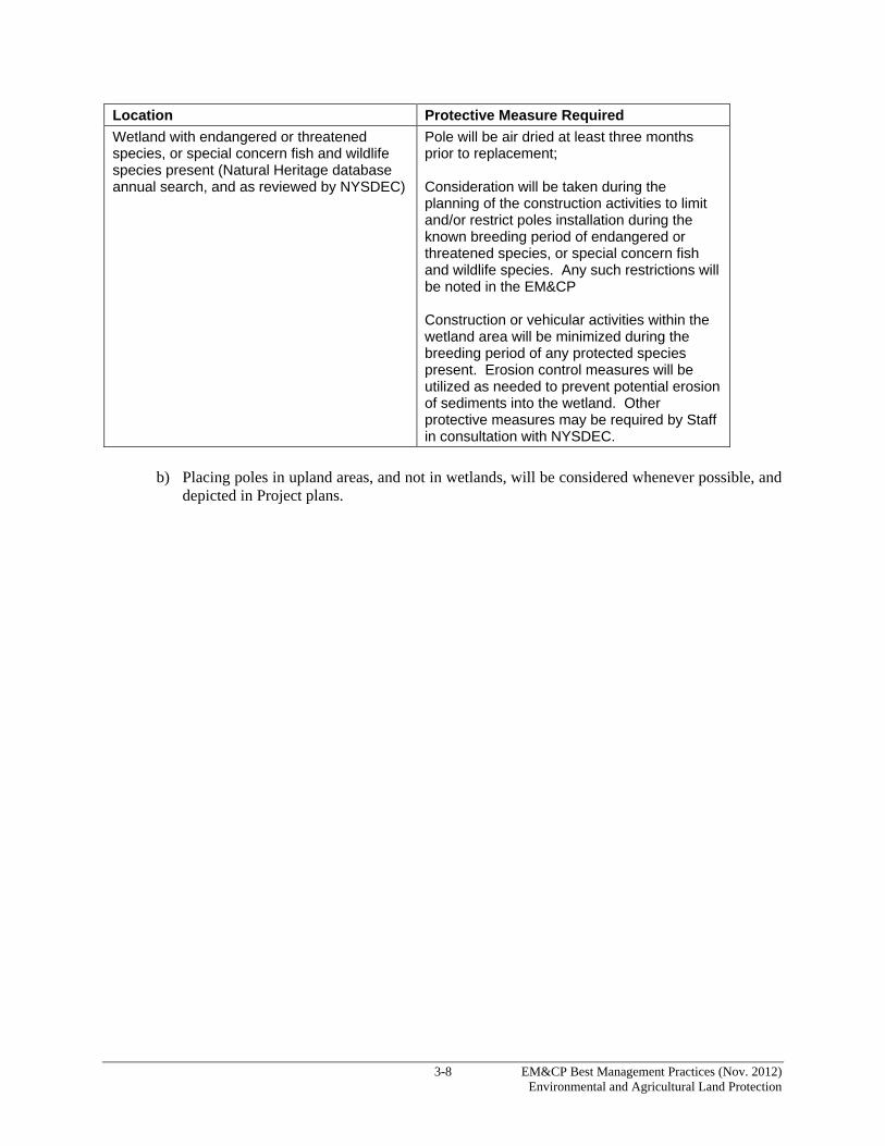
3-8 EM&CP Best Management Practices (Nov. 2012) Environmental and Agricultural Land Protection
Location Protective Measure Required Wetland with endangered or threatened species, or special concern fish and wildlife species present (Natural Heritage database annual search, and as reviewed by NYSDEC)
Pole will be air dried at least three months prior to replacement; Consideration will be taken during the planning of the construction activities to limit and/or restrict poles installation during the known breeding period of endangered or threatened species, or special concern fish and wildlife species. Any such restrictions will be noted in the EM&CP Construction or vehicular activities within the wetland area will be minimized during the breeding period of any protected species present. Erosion control measures will be utilized as needed to prevent potential erosion of sediments into the wetland. Other protective measures may be required by Staff in consultation with NYSDEC.
b) Placing poles in upland areas, and not in wetlands, will be considered whenever possible, and depicted in Project plans.

4-1 EM&CP Best Management Practices (Nov. 2012) Environmental and Agricultural Land Protection
4.0 AGRICULTURAL LAND PROTECTION PROCEDURES 4.1 EXISTING AGRICULTURAL LAND IN THE ROW The locations of pasture land, croplands, and other agricultural lands along the ROW will be shown on the P&P drawings. The Certificate Holder will retain a qualified Agricultural and Soil Conservation Specialist/Inspector (“Agricultural Inspector”) for each phase of Project development, including design, construction, initial restoration, post-construction monitoring, and follow-up restoration. The Agricultural Inspector will provide site-specific agricultural information as necessary for EM&CP development through both field review and direct contact with affected farm operators, NYS Department of Agriculture and Markets (“Ag & Mkts”), and others. The Agricultural Inspector will maintain regular contact with the Environmental Monitor and/or Construction Inspector throughout the construction phase. The Agricultural Inspector also will maintain regular contact with the affected farmers and Ag & Mkts concerning farm resources and management matters pertinent to the agricultural operations and the site-specific implementation of the EM&CP. The following standard guidelines will be applied during EM&CP development and construction within agricultural lands to the extent practicable. Site-specific details for construction and restoration within agricultural lands will be developed for the EM&CP.
a) Limit access-road width to a maximum of twenty (20) feet and, where possible, follow hedge rows, ROWs, and field edges to minimize impacts to agricultural land.
b) Locate roads that traverse agricultural fields on high-ground topography, to the extent practicable.
This offers the following advantages: 1) allows farming along the contours; 2) requires no cut-and-fill or ditching that would take additional land out of production; and 3) avoids potential drainage and erosion problems.
c) To the maximum extent possible, locate parking areas, construction-staging areas, and other
temporary and permanent support facilities outside of active agricultural fields. d) Orient guy wires for angle structures so as to minimize interference with agricultural operations
(e.g., along fence lines or in pasture land rather than in crop land). If angle structures are located in hay lands or rotation croplands, self-supporting (guyless) angle structures will be used.
e) Avoid disturbance of surface and subsurface drainage features (ditches, diversions, tile lines, etc.)
to the maximum extent practicable.
f) Identify black cherry trees (Prunus serotina) located on the ROW near active-livestock-use areas during EM&CP development. During the clearing phase, such vegetation will be disposed of in a manner which prevents access by livestock.
g) After locating all commercial sugar bushes maintained for maple syrup production within the ROW, the Certificate Holder will attempt to adjust the centerline location to avoid such operations.
h) Indicate the locations of prime, unique, and significant agricultural lands, vulnerable soils, underground drainage systems, and the locations of sites under cultivation or in active agricultural use where structures, access roads, counterpoise wires, lay-down areas, or wire-stringing

4-2 EM&CP Best Management Practices (Nov. 2012) Environmental and Agricultural Land Protection
operations will be located. Designate the site-specific techniques to be implemented to avoid or minimize construction-related impacts to agricultural resources.
i) Design the Project to the extent possible to avoid or limit the placement of structures on crop fields or on other active agricultural land where the structures may interfere significantly with normal agricultural operations or activities.
j) Prior to their usage, segments of farm roads to be used for access will be improved as required following consultation with the farm operator and Ag & Mkts. To provide stable access, such improvements could include the installation of geotextile fabric and crushed stone, or the use of temporary mats.
4.2 CONSTRUCTION PROCEDURES IN AGRICULTURAL LANDS Temporary matted access paths (a Type 3 access road) will be utilized (see Figure S14691) to prevent soil compaction and mixing. Temporary matted access paths typically should be used in lieu of topsoil-stripping and segregation along access paths. Where access is required from paved roadways to the construction area in agricultural fields, stabilized construction entrances will be installed in accordance with Figure 5A.35, or temporary mat entrances may be used where such stone apron-type entrances are not desired. Soil segregation will be implemented in active agricultural fields where underground transmission line construction is proposed per the specifications provided in Figures S14701-1, S14701-2, and S14701-3 for trenching. 4.2.1 Construction Parking, Staging, and Storage Areas All parking areas, construction-staging areas, and other temporary and permanent support facilities will be located outside of active agricultural fields to the extent practicable. The boundaries of all ROW and work areas will be identified with construction fence or other temporary markers to keep equipment from going off the approved ROW and work areas. No vehicular activity will be allowed outside the marked area without the approval of the Agricultural Inspector. With the approval of the Agricultural Inspector, and following approval as a minor change to the EM&CP, areas of active agricultural land outside the fenced or marked work areas may be available for structure lay-down and assembly, but they will not be available for equipment access. Construction materials may be stored on mats to protect the underlying soils in these areas. Upon completion of construction, mats will be removed and, if deemed necessary by the Agricultural Inspector, the soils will be de-compacted. De-compaction will be accomplished when weather and soil conditions are appropriate as determined by the Agricultural Inspector in consultation with DPS and Ag & Mkts Staff. Topsoil stockpiles on agricultural areas left in place prior to October 31 will be seeded with Aroostook Winter Rye or equal at an application rate of 3 bushels (168 #) per acre, and mulched with straw mulch at a rate of 2 to 3 bales per one thousand (1,000) square feet. Topsoil stockpiles left in place between October 31 and May 31 will be mulched with straw mulch at a rate of 2 to 3 bales per one thousand (1,000) square feet. Straw (not hay) mulch should be used to prevent soil loss on stockpiled topsoil from October through May.

4-3 EM&CP Best Management Practices (Nov. 2012) Environmental and Agricultural Land Protection
4.2.2 Vegetation Clearing and Disposal Agricultural lands often have shrubs, hedge rows, and other woody vegetation that may require clearing. In those instances, normal clearing procedures will be followed. Logs, stumps, brush, or chips will not be piled or buried in active agricultural fields or improved pasture in any manner that would interfere with the intended land use. In active-livestock pasture areas, any black cherry slash will be removed from the area. Under no circumstances are wood chips to be used as mulch in agricultural fields. 4.2.3 Structure Installation To minimize impacts when installing the transmission structures, the following guidelines will apply to the extent practicable:
a) Any grading to accommodate heavy construction equipment (e.g., cranes) and material storage/lay-down at the structure sites will be confined to the designated work area around each structure.
b) Mats will be used at the crane pad locations and other work areas to protect the underlying soil structure.
c) Erection cranes will be restricted to designated access roads and work pads at the structure sites.
d) Guy wires for angle structures should be located along fence lines or in pasture land, rather than in crop land, so as to minimize interference with agricultural operations.
e) In agricultural fields and pasture, the Contractor immediately will pick up and dispose of all
pieces of wire, bolts, staples, or other small metallic objects that fall to the ground. In addition to visual inspection of the work areas, the Contractor will use a hand-held drag magnet in active agricultural fields to canvas the work site when weather and ground conditions are appropriate, to locate and remove any small pieces of metal from the construction area that may have been missed during visual inspection.
4.2.4 Backfill and Preliminary Grading The objective of backfill and preliminary grading activities in agricultural lands is to ensure that once construction activities are completed, the agricultural soils are uniformly returned so as to restore the soil profile. To minimize impacts during backfill and preliminary grading activities, the following guidelines will apply:
a) All areas to be disturbed by excavation and backfilling will be enclosed within silt fencing or other temporary marker or barrier to define the allowable limits of disturbance. No vehicular activity will be allowed outside the marked area without the approval of the Agricultural Inspector, following approval as a minor change to the EM&CP.
b) Large stone, old foundations, and old guy anchors will be removed during construction. Stone will be removed to a non-cultivated upland area or off-ROW site. Old foundations will be removed to a depth of forty eight (48) inches
c) Excavated subsoil and rock will not be stockpiled on topsoil in active agricultural fields and
pastureland.

4-4 EM&CP Best Management Practices (Nov. 2012) Environmental and Agricultural Land Protection
d) Excess excavated subsoil and rock, or that which is not suitable as backfill will be removed from the site. On-site disposal will occur only in areas identified on the P&P drawings and with permission from the Agricultural Inspector and the landowner. Such disposal will not impact active agricultural land.
e) Any water pumped from open excavations will be directed into temporary sediment traps or filter bags prior to discharge. Pumping will be done in a manner that minimizes adverse effects on agricultural crops and operations. Surface-water ponding and soil erosion will be avoided.
f) Backfill will utilize excavated subsoil and rock whenever possible. If this material is determined to be unsuitable as backfill, select granular fill (e.g., bank-run gravel) should be utilized in its place. Excess subsoil may be graded over the exposed subsoil prior to topsoil replacement. No rock backfill is allowed in the top twenty-four (24) inches of soil in active agricultural fields.
g) All excavations will be restored to existing grade. In some areas, the excavation may be crowned an additional six (6) to twelve (12) inches to allow for soil subsidence.
Where blasting is required, such as in agricultural areas of till over bedrock, specific standards and procedures will be implemented. The till and topsoil will be returned in natural sequence to restore the soil profile. Farm owners or operators will be given timely notice prior to blasting on farm property. 4.2.5 Subsurface Drain Tiles To the extent possible, the locations of subsurface drain tiles will be identified with the cooperation of the farm owner or operator and shown on the P&P drawings, prior to construction. When working in these areas, the Agricultural Inspector will consult with the farm owner or operator and the Natural Resources Conservation Service (“NRCS”) or Soil and Water Conservation District (“SWCD”) to determine if plans or recommendations exist for the installation of future drainage in these areas. If so, construction and restoration activities will be conducted to accommodate the future drainage installation. A typical of drain tile installation is included as Figure GD-116 in Exhibit A. When in the field, the Agricultural Inspector will mark any exposed or damaged tiles revealed after grading, excavation, or topsoil stripping has occurred. If required, a site-specific plan will be prepared, in consultation with the farmer, for the replacement of functional stone drainage systems damaged during construction. If necessary, Ag & Mkts and the Soil and Water Conservation District will be consulted. 4.2.6 Clean-up and Restoration The Agricultural Inspector, in consultation with Ag & Mkts and DPS Staff, will determine if suitable weather and soil moisture conditions exist to allow for final restoration activities. Although the restoration activities in agricultural lands will vary with soil type, land use, and topography, the following general guidelines will apply:
a. Excess gravel or fill and any debris associated with transmission line equipment or parts, including old insulators, will be removed from along access roads, around structures, and in temporary parking and staging areas.
b. Compaction tests will be made for each soil type identified along the affected agricultural
portions of the ROW and Type 1 and 3 access roads in agricultural lands. Compaction testing will be conducted by the Agricultural Inspector utilizing a soil penetrometer. The compaction test results within the ROW will be compared with those of the adjacent off-ROW portion of the
4-5 EM&CP Best Management Practices (Nov. 2012) Environmental and Agricultural Land Protection
affected farm field, road, or soil unit. Where representative density on the ROW exceeds the representative subsoil density adjacent to and outside the ROW, additional shattering of the soil profile will be performed using a deep ripper, heavy-duty chisel plow, or, angled-leg subsoil tool, as determined by the Agricultural Inspector in consultation with Ag & Mkts. Deep shattering will be applied during periods of relatively low soil moisture to ensure the desired mitigation and to prevent additional compaction. Areas affected by the Project, whether farm roads, tractor paths, or active agricultural fields, will be returned to pre-construction conditions, or better..
c. Compacted soils will be de-compacted to a minimum depth of eighteen (18) inches. De-
compaction will be conducted prior to topsoil replacement. De-compaction of unimproved roads over otherwise- undisturbed agricultural land may be required in the judgment of the Agricultural Inspector in consultation with Ag & Mkts.
d. Following de-compaction, the surface will be rock-picked to remove all rocks measuring four (4)
inches or greater.
e. Where topsoil stripping may be required, stockpiled topsoil will be returned to all disturbed agricultural areas. Topsoil will be re-graded to match original soil profile and contours.
f. In the event that subsequent construction or clean-up activities result in new compaction,
additional deep tillage will be performed to alleviate compaction. g. The surface of the re-graded topsoil will be disked and, if necessary to restore natural soil profile
and surface conditions, rocks over four (4) inches will be removed from the soil surface. h. Restored topsoil will be stabilized by seeding and/or mulching in accordance with guidance
provided by the Agricultural Inspector, in consultation with the landowner or farm operator. Straw is the preferred mulch. If straw is not readily available, the Contractor may use the affected farmer’s hay as mulch. If the farmer’s own hay is not readily available, local hay may be used as mulch with the agreement of the farmer and in consultation with the Agricultural Inspector. Under no circumstances are wood chips to be used as mulch in agricultural lands.
i. Soil de-compaction and topsoil replacement should not be performed after October 1 or prior to
May 1, unless approved on a site-specific basis by the Agricultural Inspector in consultation with DPS or Ag & Mkts.
j. All permanent access roads will be re-graded as necessary to create a smooth travel surface, allow
crossing by farm equipment, and prevent interruption of surface drainage. Temporary water bars and culverts will be removed if they no longer are necessary.
k. Following restoration of all disturbed areas, excess topsoil will be distributed in agricultural areas
of the site, provided this is practicable and can be accomplished without having any adverse impact on site drainage. All such activity will be as directed by the Agricultural Inspector in consultation with Ag & Mkts and incorporate guidance provided by the landowner.
l. Any surface or subsurface drainage features damaged during construction will be repaired or
replaced as necessary. m. Upon completion of restoration, all construction debris, including debris on guying-wire
assembly and disassembly sites, will be removed and disposed of at an appropriate offsite location.
4-6 EM&CP Best Management Practices (Nov. 2012) Environmental and Agricultural Land Protection
n. If structures are removed from agricultural fields, the areas will be restored to allow agricultural
activities. Such restoration will include the removal of all vegetation from the structure area and grading of the ground surface to match the adjacent field. All rocks of at least four (4) inches will be removed from the surface.
o. Re-located or damaged fencing or gating will be restored to “like new” condition in its original
location either following construction or as otherwise agreed to with the landowner. The base of all new posts will be secured to a reasonable depth below the surface to prevent frost heave.
4.2.7 Re-vegetation in Agricultural Lands Seed mixtures for use on agricultural lands will be determined in consultation with the farm owner or operator and the relevant Soil and Water Conservation District. Lime and fertilizer rates will be chosen in the same manner. If the timing of construction precludes the re-establishment of crops for a given year, an annual cover crop will be planted to protect the disturbed area, with farm owner or operator approval. Plantings will be done in the appropriate season for the particular seed mixture proposed. Seed, lime and fertilizer will be applied in accordance with Ag & Mkts Fertilizing, Lime, and Seeding Recommendations for Restoration of Construction Projects on Farmlands in New York State, Rev. 9-25-2012 (see Specification in Exhibit A). If mulching is necessary, only straw mulch will be used over seed beds. On steep, active agricultural slopes, temporary diversion berms, soil, or straw (or similar material) bales may be used to control erosion. If dirt is used, it should be made with topsoil and in connection with a version scaled down from the typical diversion berm. The soil diversion berm should be no higher than between six (6) and eight (8) inches so that it can be worked easily by the farmer during planting time. If straw bales are used, the area under the bales will need to be re-seeded with the appropriate seed mix upon removal. 4.2.8 Agricultural Remediation and Monitoring A remediation and monitoring program will be conducted for no less than two (2) years immediately following the complete activation of the transmission line or the completion of initial ROW restoration, whichever occurs later. The purpose of this monitoring is to: (1) identify any remaining agricultural impacts associated with construction that are in need of mitigation, and (2) implement the follow-up restoration. The two-year period allows for the occurrence of the effects of climatic cycles (e.g., frost action, precipitation, seasonal changes) from which various monitoring determinations can be made. During the remediation and monitoring period, the Agricultural Inspector will determine if crop productivity on the ROW is less than crop productivity on adjacent land off the ROW. If the crop productivity within the affected ROW is less than crop productivity on the adjacent (unaffected) agricultural land, the Agricultural Inspector, in cooperation with the farm owner or operator and Ag & Mkts, will help to determine the appropriate rehabilitation measures to be implemented. After completion of the specific remediation period, the Certificate Holder will respond to reasonable requests of farmland owners or operators to correct Project-related effects on impacted agricultural resources. The following general guidelines apply during the remediation and monitoring period:
a. Crops will be monitored during the early stages of crop growth, at the middle of the growing season (July), and at the end of the growing season prior to harvest.

4-7 EM&CP Best Management Practices (Nov. 2012) Environmental and Agricultural Land Protection
b. General conditions which should be monitored include topsoil thickness, relative content of rock and large stones, trench-settling, crop-production, drainage, repair of severed fences, etc. Particular attention should be paid to changes in soil moisture content due to construction-related impacts on surface and subsurface drainage.
c. Topsoil deficiency and uneven soil-settling will be mitigated with imported topsoil that is consistent with the quality of topsoil on the affected site. A determination of whether there are excessive amounts of rock and oversized stone material in a given disturbed area will be made by comparing the results of a visual inspection of that area to what is observed when making a visual inspection of portions of the same field located outside the construction area. All excess rocks and large stones will be removed and disposed of in an appropriate area as approved by DPS and Ag & Mkts staff.
d. Properties crossed will be evaluated for the need for parallel drain tiles or other water-control devices after restoration and re-vegetation.
e. Impacts will be identified through on-site monitoring and through contact with respective farmland operators. Any proposed mitigation measures should be reviewed by the Agricultural Inspector and may be subject to approval by DPS and Ag & Mkts.
f. When the crop productivity within affected areas is less than crop productivity within adjacent unaffected agricultural land, the Certificate Holder, as well as other appropriate parties, will help to determine the appropriate rehabilitation measures to be implemented.
Written crop monitoring reports will be submitted to DPS and Ag & Mkts staff at the conclusion of each growing season during the monitoring period. Crop monitoring reports should identify sites where crop yield data indicate the need for follow-up restoration and include recommendations for remedial efforts intended to return the affected farmland to pre-construction yields/condition.

5-1 EM&CP Best Management Practices (Nov. 2012) Environmental and Agricultural Land Protection
5.0 GENERAL CLEAN-UP AND RESTORATION PROCEDURES 5.1 CLEAN-UP PROCEDURES Clean-up and disposal of cleared vegetation will be ongoing during pruning and clearing activities and in accordance with specifications and procedures enumerated in the EM&CP. Cleared vegetation will not be burned or buried; it will be disposed of in accordance with the appropriate area-specific slash disposal technique as prescribed on the P&P drawings, and Invasive Species Control Procedures in Section 7. During construction, the ROW will be kept free of debris and discarded material to the extent possible. As construction continues, each section of the ROW will be thoroughly cleaned within one week after construction is completed on that particular section. All fabricated debris resulting from construction will be disposed of at an approved disposal site in compliance with all appropriate environmental regulations. Fabricated debris generated during construction includes piping, fencing, wiring, and any other materials used during construction. Trucks leaving the construction area will be loaded, pruned, and covered in accordance with applicable regulations. Under no circumstances will any fabricated debris be burned or buried either on or off the ROW. Before completion of site restoration and to the extent possible, all debris lost from the work area by wind or high water will be recovered for proper re-use or disposal. Excavated materials removed from culverts during maintenance will be disposed of at an approved upland site located at least one hundred (100) feet from any waterbody, including freshwater wetlands and freshwater wetland adjacent areas. 5.2 RESTORATION Restoration is the final stage of transmission line construction. Considering the primary need of the ROW to remain compatible with the operation of the transmission line or substation, to the extent practicable and consistent with the Invasive Species Control Procedures identified in Section 7, the ROW will be restored to its original condition when construction is completed. Restoration activities may vary with the specific area to be restored. Restoration activities for agricultural lands and wetland areas will be presented in separate procedures in the EM&CP. Restoration activities for non-agricultural, non-residential, and urban/residential areas are presented below. 5.3 RESTORATION IN NON-AGRICULTURAL AND NON-RESIDENTIAL AREAS 5.3.1 Grading To prevent erosion and to hasten restoration of rutted skidways, access roads, staging areas, and stream banks, all disturbed areas in a particular segment of ROW will be back-bladed and restored to original contours within three (3) months after the completion of construction along that segment unless seasonal limitations preclude final restoration within this timeframe. Where transmission line construction has changed the grade and contour along the ROW, the area will be restored to original grade unless otherwise prescribed on the P&P drawings. Ruts and rills will be filled during grading. Exceptions will be made only when changes in grade are desired and requested by the landowner to improve the area, or are necessary for the safe and efficient maintenance and operation of the facility. Where the trench or pole-backfill area has settled below ground level, it may be necessary to import topsoil to return an area to grade.
5-2 EM&CP Best Management Practices (Nov. 2012) Environmental and Agricultural Land Protection
All permanent drainage and erosion-control measures will be installed during final grading. These devices will be detailed on the P&P drawings. Where needed for ongoing drainage and erosion control, permanent devices will replace temporary devices installed during construction. Unless a plow, jacking, or “Ditch Witch”-style trenching tool is used, double-ditching for trenching (i.e., the separation of topsoil from subsoil) and backfill/restoration will be required in wetlands. Subsoil will be back-filled first. Topsoil then will be replaced to maintain original contours. Disposal of surplus subsoil in wetlands or wetland adjacent areas is prohibited. Appropriate native upland or wetland vegetation will be established (as appropriate) on all disturbed areas no later than upon completion of the Project. Restored areas should demonstrate at least eighty percent (80%+) cover area survival after two growing seasons. Restoration will be accomplished through either allowing the native seed bank to re-establish or using an approved conservation seed mix. Upland spoil-disposal areas and areas of soil disturbance in the wetland adjacent area will be graded, seeded with a native seed mix, and mulched at each job location as the Project advances. All seeding should take place within one week of final grading at each location. If seeding is impractical due to the time of year, temporary mulch should be applied as soon as practical, and will be maintained until the completion of final restoration. Final restoration will take place during the first period after Project completion, as soon as weather conditions favor germination and growth. High-organic soils will be graded back to original contours and left unmulched and unseeded to facilitate the germination of native seeds and the sprouting of rhizomes from the soil bank. Soil disturbances within mineral soil, wetlands, or wetland adjacent areas must be mulched within one week of final grading to stabilize the soils. 5.3.2 Soil Stabilization, Aeration, and Fertilization in Landscaped Areas Soil compaction in construction areas frequently occurs as a result of the movement of heavy equipment over soil. Soil compaction will be avoided to the maximum extent possible through the use of low-impact equipment (i.e., high-flotation-tracked vehicles or vehicles equipped with flotation tires), particularly in previously-landscaped areas; however, if compaction occurs, soils will be aerated. Aeration in grassy areas should be accomplished through the use of a mechanical power aerator. Following use of the aerator, the area will be thoroughly raked. If soil is compacted below trees, the area below the tree canopy will be aerated by probing holes in the soil, which then will be backfilled with clean sand. In non-residential or non-agricultural areas where landscaping is to be provided, topsoil will be applied to an appropriate depth where vegetation plantings are to be re-established. When appropriate, the subsoil surface will be scarified or tilled to permit the bonding of the topsoil to the subsoil. Excess soils may be removed from the site. To permit maximum vegetative reproduction of lawns in the ROW, the topsoil will be cultivated to a depth of six (6) inches by a mechanical tiller, with special care taken around trees to avoid root damage. If a mechanical tiller cannot be used, then the inaccessible areas will be cultivated by hand. Foreign materials and contaminated soils will not be used for topsoil. Following placement of topsoil, the area will be raked and large stones, rocks, and weeds will be removed. The replaced soil will be properly graded to conform to the original contours and grade. The topsoil will be workable and applied under dry conditions, and will be either obtained from the immediate area or imported.

5-3 EM&CP Best Management Practices (Nov. 2012) Environmental and Agricultural Land Protection
Fertilizer will be applied to all areas receiving vegetation plantings. Planting strips and other areas where grasses will be planted will receive fertilizer. Fertilizer rates will depend on tree size and fertilizer type. Fertilizer over grassy areas will be evenly broadcast and cultivated or watered into the soil. Fertilizer application for trees will be distributed manually or with approved hydro-pressure equipment in holes eighteen (18) inches deep within the tree canopy. Fertilizer for planting strips and other areas where grasses will be planted will be applied at a depth of four (4) inches with discs, a spring-tooth harrow, or other equivalent piece of equipment. Fertilizer will be applied under the direction and supervision of the Environmental Monitor. 5.3.3 Mulch Application Mulch will be applied to areas that will be seeded in erosion-prone locations and also can be used to protect areas brought to final grade at an unfavorable time for seeding or transplanting. The areas then can be planted when the time is appropriate without removing the mulch. Mulch also will be applied in the immediate vicinity of replacement plants to encourage the downward movement of surface water. Mulching reduces loss of soil moisture by evaporation and decreases the possibility of seedling damage from soil-heaving caused by freezing and thawing. Mulch will be spread uniformly in a continuous blanket of sufficient thickness (typically one [1] to two [2] inches). The mulch may be spread by hand or machine. Mulch may be spread before, but no later than three days after, planting. Anchorage such as jute mesh will be used as required. For standard mulching, the Contractor will provide clean, local, salt-free threshed straw of wheat, rye, oats, or barley, to the extent practicable. Hay mulch from local sources may be used, as appropriate. When used after seeding, mulch will be applied at a rate of ninety (90) to one hundred (100) pounds (2-3 bales) per one thousand (1,000) square feet 2 tons/acre (100-120 bales) in accordance with the NYSSESC. Wood chips or other suitable materials may be used for mulching as available and appropriate 5.3.4 Vegetation Plantings Vegetation restoration in specified areas in cooperation with affected landowners will include preparation of the soil for subsequent plantings, application of topsoil on unpaved areas, and the replacement of damaged and removed trees, shrubs, and ground cover, in accordance with local guidelines, P&P drawings, and construction drawings. Vegetation restoration also includes the maintenance of lawns and plantings for specified time periods and the replacement of unsuccessful plantings. Vegetation plantings will be performed by a qualified landscape or nursery contractor. The restoration of landscaped areas will reflect applicable local standards or guidelines. In addition, and to the maximum extent possible, trees, shrubs, grass, and groundcover plants inadvertently removed, damaged, or killed as a result of construction activity will be replaced with their equivalent type, except where:
a) The approved EM&CP permits otherwise; b) An equivalent-type replacement would interfere with the proper clearing, construction, operation,
or maintenance of the facility; c) Replacement would be contrary to sound ROW management procedures or to any approved long-
range ROW management program applicable to the Project; or d) A property owner on whose land the damaged or destroyed trees or shrubs were located declines
replacement. e) Replacement would involve invasive species
5-4 EM&CP Best Management Practices (Nov. 2012) Environmental and Agricultural Land Protection
The Contractor will retain a qualified specialist to conduct an assessment of damage to trees and shrubs one growing season following construction to record latent damage. The qualified specialist will determine construction-related damage, with consideration given to the condition of the vegetation at the time of construction. The qualified specialist will identify all trees, shrubs, and groundcover plants necessary for replacement and will supervise the plant replacement. Whenever possible, replacement trees, shrubs, and other groundcover plants will be of the same species as those damaged or removed, other than invasive species. The American Standard for Nursery Stock (ANSI Z60.1-1986) will provide the necessary standards for plant replacement. The Forester will ensure that all plants meet the necessary standards. Plants which fail to meet ANSI specifications will be rejected. From the time they leave the nursery until the time of planting, all plants will be protected, as appropriate, from damage or drying. Under the direction of the Forester, the qualified nursery will plant, dig, transplant, fertilize, and replace all plant material. The Forester will ensure that the nursery follows New York State Department of Transportation (“NYSDOT”) standard planting specifications for tree and shrub plantings (see Figure 611-01 in Exhibit A). 5.3.5 Groundcover Restoration Grass areas that are damaged will be seeded under supervision of the Environmental Monitor. Grass seed will be of fresh, clean, certified crop seed. Seeding operations will commence only after an acceptable seedbed has been established, as presented above. Seed will be applied by hand, cyclone seeder, drill, or culti-packer-type seeder at a depth of ¼ to ½ inch. Hydro-seedings which are mulched need not be worked into the soil. The seedbed will be firmed following seeding operation with a roller or light drag, except where culti-packer-type seeders or hydro-seeders are used. The entire seeded area will be watered with a fine spray until a uniform moisture depth of one inch (1”) has been obtained. Mulching and anchoring the mulch may be necessary in some areas. Fertilizer will be added at the appropriate rates after seed is applied. Seed and fertilizer will be applied in accordance with the NYSSESC (see Specifications in Exhibit A). 5.4 RESTORATION IN URBAN/RESIDENTIAL AREAS Construction in urban or residential areas may require a variety of restoration activities. Above-ground and underground structures (e.g., those related to water and gas services), street pavements, curbs, sidewalks, and other features may require repair or replacement as a result of construction. Curbs, sidewalks, and streets damaged by construction will be restored to a condition “as good as, if not better than,” that which existed prior to construction. The Certificate Holder will consult, where applicable, the municipal roads or highway department, or the Regional Office or County Engineer of the NYSDOT, and incorporate applicable specifications for curb or street restoration (see Figure 611-01 in Exhibit A). Except where replacement would inhibit or impair the safe operation of a transmission line, shade trees and ornamental shrubs disturbed or damaged by construction will be repaired or replaced, as necessary, following construction. All vegetation replaced will have a minimum one-year survival guarantee. Limbs damaged by construction activities will be pruned to arboricultural specifications. Root loss or damage due to construction or construction-related soil compaction will be addressed by a trained arborist, and any prescribed treatments will be followed. Yards, lawns, agricultural areas, and other improved areas will be returned to a condition at least equal to the condition that existed at the start of the Project.

5-5 EM&CP Best Management Practices (Nov. 2012) Environmental and Agricultural Land Protection
5.4.1 Planting Time Periods For optimum survival and success, deciduous plants will be planted from approximately March to May or from approximately October to December. Evergreen plants may be planted from approximately April to May or from approximately September to October. No planting will be conducted in frozen topsoil or when the soil is in an unsatisfactory working condition, as determined by the Environmental Monitor. If grassy areas are approved for seeding, then seeding will be conducted during optimal time periods, which are approximately between April and May for spring seeding and approximately between August and September for fall seeding. Seeding will not be permitted during high winds or when the ground surface is too wet or too dry for proper working. 5.4.2 Plant Inspection, Guarantee, and Maintenance The Environmental Monitor or Forester will inspect plants in containers prior to planting and will inspect plant locations to verify compliance with local guidelines and requirements. To ensure that any previous deficiencies have been cured, the Environmental Monitor also will conduct: (1) an inspection after completion of planting; and (2) a final inspection at the end of the maintenance period. Restored areas should have eighty percent (80%) permanent ground cover within one growing season following construction. Seeded areas will be evaluated and re-seeded as necessary to achieve eighty percent (80%) cover at the optimum time or by the following growing season (two growing seasons after construction is complete). Weekly SWPPP-related inspections must be conducted until at least eighty percent (80%) revegetation of disturbed areas has occurred (except for winter periods when only monthly SWPPP inspections may be appropriate). All plants will be guaranteed to survive for at least one year or for the duration of one full growing season, beginning after the last planting is complete, whichever is longer. At the end of the guarantee period, any dead, unhealthy, or badly-impaired plants will be replaced. All replacement plants will be of the same species and size as the plants they are replacing. 5.4.3 Restoration of Walls and Fences In a few locations, the ROW traverses stone walls and fences serving as property boundaries or in place for other purposes. Unless otherwise directed by the landowner, walls or fences will be restored or replaced during the restoration period. When stone walls are encountered during construction, the following guidelines will apply:
a) Stone walls will be photographed before construction, and the landowner will be consulted regarding the level of restoration to be performed after construction;
b) Wall stone will be carefully removed, stockpiled, and re-used, or comparable replacement stone will be used;
c) Walls will be restored to a comparable standard of material and design, unless otherwise agreed to by the landowner;
d) Walls of historical or archaeological significance will be restored using original stone, in accordance with both the landowner and permitting conditions; and
5-6 EM&CP Best Management Practices (Nov. 2012) Environmental and Agricultural Land Protection
e) At landowner direction, walls of lesser quality (e.g., loose piles used for field separation or all-terrain-vehicle control) or fencing may be substituted for the original stone wall.
When fences (wood, wire, mesh, etc.) and gates are encountered during construction, the following guidelines apply:
a) Landowner will be consulted prior to removing fencing during construction;
b) Unless otherwise agreed to by the landowner, segments of fences and gates affected by construction will be restored to a comparable standard of material and design upon completion of construction;
c) The base of all new posts will be secured to a reasonable depth below the surface to prevent frost heave;
d) Existing fencing will be dismantled and stored for re-use where practical; and
e) During restoration, new fencing material will be used if the original fencing material is damaged.
Examples the types of gates and fences that may be used during the Project are included in Figure GD-118 in Exhibit A.

6-1 EM&CP Best Management Practices (Nov. 2012) Environmental and Agricultural Land Protection
6.0 ACCESS ROAD TYPES AND DEFINITIONS 6.1 CONSTRUCTION ACCESS ROADS Prior to the commencement of construction, Contractors will review the P&P drawings relating to access to each structure in the ROW. Generally, construction access will be accomplished within the Project transmission ROW. ROW and off-ROW access-road alignments will be shown on the individual P&P drawings. Access paths will be no more than twenty (20) feet wide. In certain specified areas, off-ROW access will be required in order to avoid crossing sensitive resources, provide safe work areas, or facilitate equipment-staging. As much as possible, access will be routed to avoid areas of unstable soils, steep slopes, wetlands, and streams. Streams, wetlands, and other water resources will be field-delineated along all proposed access roads, subsequently verified by the U.S. Army Corps of Engineers (“USACE”) and NYSDEC, and then shown on the P&P drawings. The types of access that will be used during the Project are described below. 6.2 ACCESS TO ROW FROM PUBLIC ROADS A stabilized construction entrance will be installed at the intersection of the ROW and each public road or street where equipment could track mud onto public travel lanes. Detailed specifications include the placement of approximately six (6) inches of #4 size stone on geo-textile fabric extending fifty (50) feet into the ROW, are provided as Figure 5A.35 in Exhibit A, and locations will be provided on the P&P drawings. 6.3 MAINTENANCE OF EXISTING ACCESS ROADS AND ROUTES In many cases, an existing access road may need to be repaired or improved to allow passage of the heavy equipment needed for construction activities, and to avoid excessive rutting. Ruts and depressions along existing access routes and within the existing ROW may be leveled and graded. Minor improvements may include adding gravel fill or crushed stone to fill depressions and washed-out areas that present unsafe conditions or might jeopardize environmental compliance. For access roads where vegetation impedes construction access, the need for hand-clearing, mechanical clearing, mowing, or a combination of any of these methods will be identified to establish the alignment and width of the access road. Cleared material will be either: (a) chipped and spread along the access road, or (b) hand-piled or mechanically piled along the edge of the access road or ROW, except that in state-regulated wetlands, all slash not cut and left in place shall be removed from the wetland. No slash will be collected and permanently piled in the state-regulated wetland, whether adjacent to an access road or not. Woodchips and other debris from clearing activities will be removed from agricultural fields. Access-road improvement areas will be identified on the P&P drawings. Some sections of off-ROW access roads utilize existing farm roads. The majority of these farm roads are routed along field edges, and are typically utilized infrequently by the farm operator for field access. Unless the proposed off-ROW access route is a well-defined farm road (heavily compacted, no vegetation, etc.), timber matting or topsoil stripping will be required. Unless “tractor paths” or “unimproved roads” appear like the farm driveway, they should be treated the same as an agricultural field. Anything that is determined to be a legitimate or clearly defined farm road will be restored to at least original condition, if not better. Under no circumstances should ROW clearing or electrical contractors be allowed vehicle/equipment access onto or along agricultural fields (including field edges, or unimproved “tractor paths”) without the use of timber mats or soil segregation. All construction activities in agricultural fields, including equipment and vehicle access for clearing, will be conducted on
6-2 EM&CP Best Management Practices (Nov. 2012) Environmental and Agricultural Land Protection
timber matted or topsoil-stripped travel and work areas. If questions arise as to the designation or status of proposed use of field edges, “unimproved roads”, or “tractor paths” for vehicle and equipment access, Ag & Mkts will be notified and the area in question will be field-reviewed by staff and a mutual determination will be made prior to construction. Modifications regarding access road location or type within agricultural lands will only be made following proper approvals from DPS Staff. 6.4 ACCESS ROAD TYPES There are three types of access roads typically used and specified on the EM&CP Plan & Profile drawings for the Project. 6.4.1 Type 1: Unimproved Access Roads (see Figure S14693 in Exhibit A) Type 1 access roads, which are unimproved access roads, and which may be either temporary or permanent, include: (a) those existing roads or paths specified for use across upland areas, and (b) existing agricultural roads. Type 1 access roads may occur within wetlands or other sensitive lands in the ROW with special provisions, such as: only low-ground-pressure, flotation, or tracked vehicles may use these roads. Where necessary in non-sensitive areas, drainage-conveyance and erosion controls will be installed by the Contractor. In addition, where unstable soil conditions occur in agricultural upland areas, the use of cut material made available by the clearing of the ROW may be used for the installation of corduroy or brush-mat to provide support for clearing and construction equipment. The material used can consist of both larger diameter non-merchantable logs and limbs and small diameter slash. Locations where corduroy and/or brush-mat are proposed for use should be determined during the development of the EM&CP and should be shown on the P&P drawings. To the extent that Type 1 access roads are used for continued ROW maintenance in non-sensitive areas, these roads may be considered permanent. 6.4.2 Type 2: Permanent, Stabilized Access Roads (see Figure S14694 in Exhibit A) Type 2 access roads, which are permanent, stabilized access roads, are specified for those areas where work related to certain structure types, including dead-end or angle structures with concrete foundations, requires particularly heavy equipment. Work relating to these structures requires large excavators, all-terrain cranes, haul trucks, and concrete trucks. Construction standards specific to Type 2 access roads will apply to the upgrading of existing access roads to Type 2 specifications and where new Type 2 access roads may be required. Type 2 access roads will be located only in upland areas and will consist of a compacted sub-grade and a surface course of crushed stone on filter fabric. Type 2 access roads may be used for long-term ROW maintenance activities. Where necessary, drainage and erosion-control devices will be installed at the direction of the Construction Manager or the Environmental Monitor. 6.4.3 Type 3: Temporary Access Roads (see Figures, S14689, S14691 and S14695 in Exhibit A) Type 3 access roads are temporary access roads used in sensitive areas (e.g., wetlands, agricultural lands) or areas of unstable soils. Some Type 3 access roads are wetland-specific. In delineated wetland areas and state-regulated wetlands, the use of low-impact equipment (i.e., low-load-bearing tracked vehicles or vehicles equipped with flotation tires) or mats will be used in conjunction with temporary, Type 1 access roads or paths to the maximum extent practicable. The use of multiple access or construction routes within a wetland in order to increase the number of vehicle trips through a wetland without using mats is not an authorized Type 3 access. The allowable options for Type 3 wetland access roads include: (1) mats; (2) bridges; and (3) flotation devices and (4) corduroy or brush mat provided that all material is removed from the wetland and regulated buffer areas upon completion of construction. The type of

6-3 EM&CP Best Management Practices (Nov. 2012) Environmental and Agricultural Land Protection
access road to be installed in a particular wetland area will be determined by the Construction Manager and the Environmental Monitor. If the Construction Manager determines that conditions are unsuitable for low-impact equipment with Type 1 access roads or paths, then a Type 3 wetland access road will be installed. Vehicular travel through the wetland area with low-ground-pressure equipment will be confined to the access road or path-alignment-and-structure work zones, as shown on the P&P drawings. When suitable conditions exist for the use of low-impact equipment, particularly if unsaturated, dry, or frozen conditions prevail at the time of construction, the use of low-impact equipment could result in less disruption to the wetland than would the installation and subsequent removal of temporary access roads. The edges of Type 3 access roads in wetlands will be marked (i.e., staked and flagged) to ensure equipment stays on the roads. Type 3 access roads within agricultural lands will consist of timber matting, soil segregation, or other protective measures as specified on the P&P drawings and developed in consultation with Ag & Mkts. DPS Staff consultation and approval as a minor change to the EM&CP is required for modifications to Type 3 access road location within agricultural lands. 6.5 ROAD CONSTRUCTION IN WETLANDS To the greatest extent possible, permanent road construction in wetlands will be avoided, and where such road construction is unavoidable, its impacts will be minimized. In limited cases, a permanent access road may be needed to allow frequent access for inspection, maintenance, and repair. When permanent road construction in wetlands is unavoidable, the following guidelines will be followed.
a) To prevent turbidity problems and to provide stability, the use of new, clean, stabilized stone fill (i.e., crusher run, screened gravel, or cobble-absent fines passing an N 200 sieve) is required.
b) The width of the road will be the minimum needed to pass a single vehicle safely through the wetland.
c) Construction activity in wetlands will be avoided during the breeding season for any wetland- dependent endangered, threatened, or special-concern species.
d) Flow through the wetland will not be altered. Any culverts installed will comply with all conditions for culvert placement in Section 3 of the EM&CP and as identified on the EM&CP P&P drawings.
e) Any road constructed through a wetland will follow the shortest practicable distance through it. 6.6 MAINTENANCE OF EXISTING CULVERTS & FORDS Existing culverts and fords that must be repaired will be identified and located. Repair specifications will be provided on the P&P drawings of the EM&CP. Ordinary repairs to existing functional structures and facilities, repair of rip rap, and removal of debris from culverts, sediment traps, fords, and adjacent drainage channels will be made, providing that there is no dredging or filling involved, and providing that there is only minimal disturbance to aquatic life and minimal riparian effect.
a) Culvert, Fords, and Sediment-basin Maintenance: Mechanical removal of debris, silt, gravel, trash, etc., from culverts, fords, water-intake structures, or sediment basins will be allowed at regular-but- infrequent intervals. Extracted materials will be disposed of at a facility duly authorized to receive such materials.
6-4 EM&CP Best Management Practices (Nov. 2012) Environmental and Agricultural Land Protection
b) Small excavations, including, but not limited to, digging jacking pits and jacking for conduit, provided that the disturbance is temporary and excavation volumes are less than seventy-five (75) cubic yards per pit, will be allowed:
i. To avoid permanent degradation of wetland and wetland adjacent area contours, as well as conversion of habitat. In this case, excavation will not exceed seventy-five (75) cubic yards per pit, and any excess excavated materials (i.e., those not to be re-used in backfills) will be removed and disposed of at an upland site as soon as possible, and in no case later than thirty (30) days after excavation. No side-casting of excavated materials will be allowed. No fill -- whether from excavation or imported from an off-site area -- will be stored in the wetland or wetland adjacent areas.
ii. Prior to inclement weather, or if they will be exposed for more than fourteen (14) days,
excavated or temporarily stockpiled soils and materials will be covered and protected to: (a) reduce runoff of fines (which may cause a turbidity problem); and (b) prevent rainwater from soaking the materials and rendering them unsuitable for backfill. Erosion-control measures will be implemented effectively at all times.

7-1 EM&CP Best Management Practices (Nov. 2012) Environmental and Agricultural Land Protection
7.0 INVASIVE SPECIES CONTROL 7.1 HAZARD IDENTIFICATION In conjunction with developing the EM&CP, the Certificate Holder will perform the following activities to identify and address potential invasive plant species hazards:
a) Contact applicable NYSDEC Regional Natural Resource Supervisor(s) and Ag & Mkts for any Project-area information about known or potential occurrences of invasive plant species that are included in the NYSDEC’s Revised Interim List of Invasive Plant Species in New York State, (May 14, 2012) (identified in Section 7.7) and that also may be of special concern to the applicable NYSDEC Regional Natural Resource Supervisor(s).
b) In conjunction with performing field analyses and wetland delineation efforts needed to develop the project EM&CP, identify obvious locations of invasive plant species that occur along the existing or proposed ROW.
c) Assess which identified locations of invasive plant species constitute an environmental or human health hazard and warrant the prescription of measures to control the spread of such species during construction, and consider each species in its landscape context, such as whether a species is contributing positively to vegetation management of the ROW and whether the same species has been observed, or otherwise is known to be abundant, on adjacent lands.
7.2 MEASURES TO PREVENT OR CONTROL THE TRANSPORT OF INVASIVE PLANT
SPECIES On a Project-wide basis, the Certificate Holder will perform the following measures to prevent or control the transport of invasive plant species:
a) Train and educate appropriate Project contractor(s) and subcontractor(s) on (i) identifying invasive plant species and locations; (ii) site-specific prescriptions for preventing or controlling their transport throughout or off of the Project site; and (iii) the various cleaning and/or decontamination methods to be used on the Project, and as prescribed on a site-by-site basis, on the Project P&P drawings.
b) In order to prevent the potential introduction of invasive plant species from other areas or regions to the Project area, require that vehicles, equipment, and materials (including mats) be inspected for, and cleaned of, visible soils, vegetation, insects, and debris before bringing them to the Project area. On a site-by-site basis, and as prescribed on the Project EM&CP drawings, equipment and material used within the Project ROW will be cleaned prior to leaving the ROW.
c) Where practicable in upland areas identified for higher invasive species control and shown on the
Project P&P drawings, brush and wood will be chipped into a layer of between six (6) and eight (8) inches over access roads on the ROW, thus providing a barrier between plant material and equipment. The condition of these access roads will be monitored by the Environmental Monitor during construction. Provided this barrier remains intact, the Environmental Monitor may exempt specific types of potential transporters (e.g., pickup trucks and pedestrians) from decontamination requirements.

7-2 EM&CP Best Management Practices (Nov. 2012) Environmental and Agricultural Land Protection
d) To prevent or minimize the potential introduction of invasive plant species of special concern with a high probability of spreading from a heavily contaminated area within the ROW to an uncontaminated area within or outside the ROW, require that vehicles, equipment, and materials (including mats) be inspected for, and cleaned of, visible soils, vegetation, insects, and debris to the extent practicable before moving from the heavily contaminated area. Vegetation, soil, spoils, or debris that is so removed from construction vehicles should be retained within the same construction area already infected with the invasive species, or removed from the site to an approved disposal facility.
e) Install appropriate erosion and sediment controls at identified work sites to help prevent or
control the potential transport of invasive plant species via soil erosion.
f) To the extent practicable, water for dust control and other uses will come from plain water supplies/sources.
g) To the extent practicable, avoid moving invasive-plant-infested soils, gravel, rock, and other fill
materials into relatively-invasive-plant-free locations. Soil, gravel, rock, and other fill material will come from invasive-plant-free sources on the site, if such sources are available. Off-site fill materials also will come from invasive-plant-free sources, if such sources are available.
h) To the extent practicable, stabilize and re-vegetate disturbed sites using soil components and
mulches obtained from non-invasive plant sources. Utilize seed and other plant materials that have been checked and certified as noxious-weed-free.
7.3 WETLANDS AND WATERBODIES To prevent the potential introduction of invasive plant species into wetland and waterbodies from other areas the following measures will be taken: Before equipment and materials are used in any Project work area involving wetlands and waterbodies, regardless of the federal or state designation, the equipment will be inspected for, and cleaned of, any visible soils, vegetation, and debris. To reduce the risk of the spread of seeds, roots, or other viable parts of invasive plant species to and from these specific water-related resources, in connection with work activities in and adjacent to wetlands and waterbodies, irrespective of federal or state designation, The Certificate Holder should implement the measures stated above. Upon the completion of construction activities in wetlands and waterbodies within the Project area, wetland mats should be removed, by lifting in reverse order, and cleaned. Where the NYSDEC has identified the presence of Didymosphenia geminata (Rock Snot or Didymo), any footwear used in streams or waterbodies should be disinfected before leaving the site. After crossing any waterbody known to be infected with Didymo, or any waterbody connected to a stream or waterbody known to be infected with Didymo , equipment will be thoroughly cleaned immediately after leaving the water body. Specific measures to control Didymo, if identified on site, will be included in the EM&CP. 7.4 UPLAND INVASIVE PLANT SPECIES

7-3 EM&CP Best Management Practices (Nov. 2012) Environmental and Agricultural Land Protection
If upland invasive species must be cut within the Project area during construction, the slash will be disposed of as described in Section 7.5. The Forester and the Environmental Monitor(s) will determine the best method of control (i.e., slash removal, spraying stumps, or both) on a species-specific and a site-specific basis. 7.5 DISPOSAL OF WOOD, PLANT MATERIAL, SOIL, AND DEBRIS Loose plant and soil material that has been removed from vehicles, equipment, and materials, or generated from the cleaning operations should be retained within the same construction area that is infested, provided that no filling of any wetlands or adjacent areas should occur as a result or properly disposed of off-site. 7.6 INVASIVE INSECT CONTROL In an effort to control the spread of invasive insects, the Certificate Holder will:
a) coordinate with outside logging contractors for sale and use of the merchantable timber that will be cleared;
b) as applicable, provide un-merchantable timber as firewood to adjacent landowners or the general public pursuant to the NYSDEC’s firewood restrictions to protect forests from invasive species found in 6 NYCRR Part 192.5; and
c) make sure crews are trained to identify the Asian Longhorned Beetle and the Emerald Ash Borer (EAB) and any other insects that the NYSDEC identifies as a potential problem. If these insects are found, they will be reported to the NYSDEC regional forester.
d) ensure that any EAB-infected ash (Fraxinus sp.) trees harvested during the Project either: (1) remain on site in a manner or location that minimizes the risk that the trees will be removed from the ROW; (2) are chipped; or (3) are transported to a wood-using facility pursuant to appropriate Emerald Ash Borer compliance agreements, in accordance with NYSDEC regulations and applicable Quarantine Orders relative to the EAB.
7.7 LIST OF INVASIVE PLANT SPECIES Invasive species are defined in Section 19-1703(10) of the Environmental Conservation Law as a species that is:
a) non-native to the ecosystem under consideration; and b) whose introduction causes or is likely to cause economic or environmental harm or harm to
human health. For the purposes of this paragraph, the harm must outweigh significantly any benefits.
The Revised Interim List of Invasive Plant Species in New York State (May 14, 2012) compiled by the NYSDEC is available at http://www.dec.ny.gov/animals/65408.html. It is important to recognize that some of the listed shrub and tree species, such as multiflora rose, honeysuckle species, pear, and common buckthorn, have generally been considered to be desirable or compatible plant species pursuant to the LRROWMP. The occurrences of some of the listed shrub and

7-4 EM&CP Best Management Practices (Nov. 2012) Environmental and Agricultural Land Protection
tree species on existing ROWs of the Certificate Holder are due at least partially to decades of vegetation-management efforts of the Certificate Holder that have been aimed at promoting and managing such low-growing plant communities. Some, but not all, of these plants may occur in varying degrees on the Certificate Holder’s ROW. Plants on this list that do not grow to great heights, such as common buckthorn and honeysuckle, have been managed as desirable plants. Those plants that do grow to great heights, such as Norway maple, always have been managed as undesirable in transmission line ROWs. As appropriate and practicable, stumps should be treated to prevent regeneration. When conducting vegetation management as described in Section 2.0, the determination of desirability or compatibility of vegetation should also be based on whether the species is an invasive species that meets the criteria in Section 7.1(c) above. .

L2010-206 8-1 EM&CP Best Management Practices (Nov. 2012) Environmental and Agricultural Land Protection
8.0 MEASURES TO PROTECT RARE, THREATENED AND ENDANGERED FLORA AND FAUNA SPECIES AND SIGNIFICANT NATURAL COMMUNITIES
Both known and potential sensitive resources need to be protected to the maximum extent practical during construction and operation of the Project. Specific protection measures will vary by resource-specific considerations and be developed on a case by case basis in the EM&CP. Typical protection procedures for these sensitive resources are described as follows: 8.1 EXISTING RARE, THREATENED AND ENDANGERED SPECIES IDENTIFICATION Information pertaining to the location and habitat of rare, threatened and endangered (“RTE”) flora and fauna species and Significant Natural Communities is typically included as part of the Article VII Application. During the preparation of the EM&CP, the Certificate Holder should contact the NYSDEC Regional Supervisor, NYS Natural Heritage Program (“NYSDEC/NYNHP”), and the U.S. Fish and Wildlife Service (“USFWS”) to check for any updates or changes of known RTE species or habitat or Significant Natural Communities in the Project area. During EM&CP preparation, the Certificate Holder should, in consultation with DPS and NYSDEC Staff, identify appropriate protection measures for RTE species and habitat and Significant Natural Communities. These measures should be prescribed in the EM&CP. 8.1.1 Known RTE Species If the project ROW crosses a known habitat or location of RTE species, the Certificate Holder should contact NYSDEC, NYSDEC/NYNHP and the USFWS for species specific protection measures.
a) All RTE species habitat areas will be clearly marked on the EM&CP P&P drawings and clearly distinguished (flagged) in the field to ensure protection.
b) Along with the RTE habitat and community locations being shown on the plans, crews will be
trained on the locations and identification of the species in the identified areas.
c) Access through any area which is known to contain a RTE species or is the habitat of a RTE species will be avoided to the maximum extent practicable.
d) If access through the an area known to be inhabited by an RTE species or which is known habitat
of an RTE species is unavoidable the Certificate Holder will contact NYSDEC, NYSDEC/NYNHP, and the USFWS to determine appropriate protection measures to minimize impacts and identify measures to mitigate those impacts which are unavoidable.
e) Any documents or information which identifies the location or habitat of any known RTE species will be labeled CONFIDENTIAL and access will be restricted to only those persons who need to know this information. The Certificate Holder will provide appropriate training to employees and contractors as to the confidential nature of this information.
L2010-206 8-2 EM&CP Best Management Practices (Nov. 2012) Environmental and Agricultural Land Protection
8.1.2 Unanticipated Discovery of RTE Species During Construction If any RTE species (see 6 NYCRR Part 182 and http://www.dec.ny.gov/animals/7494.html for lists of RTE species) is encountered during the construction, operation or maintenance of the Project or discovered during the environmental inspection prior to construction-related activity, the Environmental Monitor will identify the extent of the area of concern, clearly mark it in the field, and GPS its location. The Certificate Holder will promptly notify Staff and the NYSDEC Regional Natural Resources Supervisor, and if appropriate USFWS, in order to determine the appropriate measures to be taken to avoid and minimize direct impacts and protect such species and species habitat. If discovery of an unanticipated RTE species is made during construction, all construction activities in the immediate area will cease to protect the species or their habitat from immediate harm. The Certificate Holder will stabilize the area and cease construction or ground-disturbing activities in the area until the appropriate officials are notified and protective measures are implemented. The Environmental Monitor will work with the Construction Manager to implement necessary protective measures identified above.
a) Update plans to reflect the new RTE species area of concern and the site will be clearly marked in the field.
b) Update crews on the new sensitive area location and species identification.
c) Label any documents or information which identify the location or habitat of any known RTE
species CONFIDENTIAL and access will be restricted to only those persons who need to know this information. The Certificate Holder will provide appropriate training to employees and contractors as to the confidential nature of this information.
8.2 SIGNIFICANT NATURAL COMMUNITIES
a) All Significant Natural Communities will be clearly marked on the Project plans and will be clearly distinguished in the field to ensure protection.
b) Access through or impact to any Significant Natural Communities will be avoided to the
maximum extent practicable.
c) If access through a Significant Natural Community is unavoidable, the Certificate Holder will develop appropriate protection measures in order to minimize impact.

9-1 EM&CP Best Management Practices (Nov. 2012) Environmental and Agricultural Land Protection
9.0 INSPECTION AND MONITORING During construction of the Project, multiple inspector/monitor(s), as required by the Certificate Conditions, will be employed to ensure that all Certificate Conditions and EM&CP requirements, plans and specifications are appropriately adhered to. The qualifications and duties of each inspector/monitor are provided as follows. 9.1 ENVIRONMENTAL MONITOR Environmental Monitor(s) should be employed full-time on the Project during construction and restoration. Additional Environmental Monitors should be utilized as appropriate. 9.1.1 Qualifications
a) Sufficient knowledge and experience to manage the environmental compliance procedures described in the EM&CP; and
b) A four-year degree in forestry or related environmental discipline or a demonstrated equivalent knowledge, in either case including courses in ecological sciences and experience in environmental construction inspection; and
c) Necessary qualifications consistent with a “Qualified Inspector” pursuant to the NYSDEC
SPDES General Permit for Stormwater Discharges from Construction Activity. 9.1.2 Responsibilities
a) Monitoring all reconstruction activities, including clearing, access and drainage improvements/installations, structure removals, replacement structure installations, wire-stringing, installation and maintenance of temporary erosion controls, work involving wetlands, streams, agricultural lands, etc.;
b) Monitoring and supporting compliance with the environmental management and protection requirements specified by the EM&CP, 401 Water Quality Certificate, and applicable USACE permits;
c) Performing or coordinating the role and responsibilities of the Agricultural Inspector in order to address all EM&CP requirements for work involving affected agricultural lands;
d) In coordination with the RGE/NYSEG Project Manager, providing DPS Staff and RGE/NYSEG Project team personnel with weekly status reports summarizing construction and indicating construction activities and locations scheduled for the next two weeks;
e) Organizing and conducting site compliance audit inspections for DPS Staff, with the Construction Inspector, Agricultural Inspector (as applicable to affected agricultural lands), and other Project team personnel;
f) In coordination with the RGE/NYSEG Project Manager, processing EM&CP Notices of Change with DPS Staff;
g) Coordinating NYSDEC, Ag & Mkts, and USACE inspections of the Project;
9-2 EM&CP Best Management Practices (Nov. 2012) Environmental and Agricultural Land Protection
h) Monitoring and managing all environmental protection requirements of the Project EM&CP and closely coordinating same with the Construction Inspector and RGE/NYSEG’s Contractor; and
i) Monitoring Contractor compliance with the provisions of the Certificate of Environmental Compatibility and Public Need (“Certificate”) issued by the PSC and all permits, applicable sections of the New York State Public Service Law, and the EM&CP.
9.2 CONSTRUCTION INSPECTOR One Inspector will be employed full-time on the Project as needed. Additional Construction Inspectors should be utilized as appropriate. 9.2.1 Qualifications
a) Ten (10) years of experience in transmission overhead line or substation construction and the operation and maintenance of transmission facilities with a strong understanding of the applicable construction standards and work methods;
b) Knowledge of federal, state, OSHA, local, and applicable environmental rules and regulations;
c) Strong interpersonal and leadership skills with self-direction and high motivation;
d) The ability to understand construction field issues, prints specification sheets, schematics, one-line diagrams, and instructional information to construct, maintain, and troubleshoot transmission lines and substation equipment;
e) A thorough understanding of electrical principles and the hazards associated with electrical transmission work;
f) A good mechanical aptitude;
g) Knowledge of applicable maintenance practices, safety requirements, and labor contracts;
h) The ability to travel throughout the service territory and work extended hours and weekends in emergency situations, as needed;
i) Strong communications skills (both verbal and written);
j) RGE/NYSEG Substation Entry Trained; and
k) North American Electric Reliability Corporation Critical Infrastructure Protection (“NERC CIP”) Clearance or the ability to meet this requirement.

9-3 EM&CP Best Management Practices (Nov. 2012) Environmental and Agricultural Land Protection
9.2.2 Responsibilities
a) Providing proactive leadership and direction to Contractor personnel to ensure that high standards of safety, security, and environmental compliance are developed and consistently maintained;
b) Working closely with Contractor personnel to ensure development of a complete Work Proposal, including construction work plan, detailed schedule, Health and Safety plan, and outage plan;
c) Ensuring that Contractor resource needs are adequately identified and assigned to fully support the construction contract work plans, schedule, and budget;
d) Taking a proactive role interfacing with the appropriate individuals to fully understand contract program needs and ensure that promised commitments are delivered on time and within budget;
e) Participating in construction conference calls and meetings to support the requirement of the Contractor to provide weekly updates and reports;
f) Assuring that assigned Contractor personnel are properly directed, trained, licensed, and evaluated within Certificate Holder guidelines and procedures;
g) Maintaining a thorough understanding of department emergency response procedures to help arrange and provide resource support as needed; and
h) Coordinating with internal and external resources for pre-construction meetings, as required. 9.3 SAFETY INSPECTOR One Safety Inspector should work part time on the Project and should be present for any higher risk procedures (helicopter work or areas with multiple line crossings) that should be conducted. 9.3.1 Qualifications
a) A bachelor’s degree -- preferably in Safety Management or a related science or engineering discipline;
b) Five (5) to seven (7) years of professional safety experience;
c) Five (5) to seven (7) years of experience in electric and/or gas operations or in a related industry, preferably in a supervisory or leadership role;
d) Certification as a safety or occupational health professional (preferred);
e) Certification as a Certified Safety Professional or other equivalent recognized credential;
f) Knowledge of federal, state, and local safety and health laws and regulations;
g) Knowledge of electric and gas operations;
h) Knowledge of RGE/NYSEG policies and procedures;
i) Knowledge of industrial hygiene principles;

9-4 EM&CP Best Management Practices (Nov. 2012) Environmental and Agricultural Land Protection
j) Excellent proven interpersonal skills coupled with the proven ability to lead in connection with various broad occupational safety and health principles in a constantly changing work environment;
k) Excellent oral and written communication skills;
l) A demonstrated ability to manage multiple high-priority tasks and engage in complex problem-solving;
m) Knowledge of management principles, especially as they relate to organizational behavior and statistical analysis;
n) A demonstrated high level of ethical behavior; and
o) Excellent judgment and decision-making skills. 9.3.2 Responsibilities
a) Assisting in the establishment and implementation of regulatory compliance and incident-prevention activities regarding the safety and health of employees, Contractor and subcontractor personnel, and the public as they interact with RGE/NYSEG operations;
b) Assisting management and directing safety specialists in analysing any serious incidents; and
c) Advising management in problem solving/decision making to eliminate hazards and to develop incident-prevention and regulatory compliance programs in order to reduce incidents that may lead to personal injury and property damage.
9.4 QUALITY ASSURANCE INSPECTOR One Quality Assurance Inspector should be employed part time on the Project as needed. 9.4.1 Qualifications
a) A bachelor’s degree and a minimum of three (3) years of experience in a quality assurance role; or an equivalent combination of technical education and training and a minimum of eight (8) years of experience in a quality assurance role;
b) Experience working with continuous improvement teams, leading or team member;
c) Ability to undertake tasks with limited supervision;
d) Demonstrated analytical skills with the ability to evaluate and produce routine reports;
e) Proficient computer skills;
f) Ability to collect, enter, analyze, track and produce data;
g) Demonstrated organization and planning skills, with the ability to schedule and perform quality audits across internal and external functions;

9-5 EM&CP Best Management Practices (Nov. 2012) Environmental and Agricultural Land Protection
h) Demonstrated oral and written communications skills;
i) Demonstrated leadership skills with self-direction and high motivation;
j) Demonstrated problem solving skills with the ability to solve complex issues;
k) Knowledge of performing International Organization for Standardization (“ISO”) or audits of other registered auditing bodies; and
l) Familiarity with construction job sites that may be in harsh climates and/or terrain, in controlled conditions, and/or require the use of Personal Protection Equipment (“PPE”).
9.4.2 Responsibilities
a) Performing quality audits on electrical transmission lines and electrical substations construction projects for Contractor and internal System Delivery crews;
b) Verifying that construction field work complies with the criteria per RGE/NYSEG Transmission Construction Specifications;
c) Writing and publishing reports detailing results of field construction audits;
d) Issuing and tracking non-conformances for items found not meeting the required specification;
e) Requiring submission of corrective and preventive action for non-conformances found;
f) Working closely and collaboratively with the Contractor, System Delivery and Project Management to validate there is a system of controls and procedures is in place and to evidence that adherence to those controls and procedures is documented and maintained in a systematic and orderly manner;
g) Updating any instructions/documents to reflect the current process;
h) Identifying “opportunities for improvement”;
i) Participating in conference calls and meetings; and
j) Writing work instructions and in-process quality statistical reporting forms and charts to support the quality program.
9.5 AGRICULTURAL INSPECTOR One part-time Agricultural Inspector will be employed by the Project as needed for review of the construction in and restoration of agricultural areas affected by the Project. If qualified, the Environmental Monitor may perform the duties of the Agricultural Inspector. 9.5.1 Qualifications
a) Sufficient knowledge and experience to manage the agriculturally-related environmental compliance procedures described in the EM&CP; and

9-6 EM&CP Best Management Practices (Nov. 2012) Environmental and Agricultural Land Protection
b) A four-year degree in agricultural science, environmental science or a related discipline or demonstrated equivalent knowledge, in either case including courses in agricultural and ecological sciences and experience in agriculturally-related environmental construction inspection.
9.5.2 Responsibilities
a) Monitoring all reconstruction activities involving affected agricultural lands, in coordination with the Environmental Monitor, the Construction Inspector, farm operators, Contractor, Ag & Mkts staff, and DPS Staff, in accordance with the EM&CP;
b) Communicating and coordinating closely with affected farm operators; and
c) Monitoring and supporting compliance with agricultural-land-related Ordering Clauses/Certificate Conditions and all other applicable EM&CP provisions.

10-1 EM&CP Best Management Practices (Nov. 2012) Environmental and Agricultural Land Protection
10.0 POLLUTION PREVENTION Proper material storage, handling, and disposal practices coupled with spill prevention, control and countermeasures procedures will be implemented during the construction period to reduce the risk of exposure of materials and hazardous substances to stormwater or the environment. 10.1 POTENTIAL POLLUTANT SOURCES Table 10-1 summarizes some of the types of materials that may be found at work sites during construction of the Project.
Table 10-1: Potential Pollutant Sources for Construction Activities Pollutant Quantity Container and Storage Description
Medium Weight Used Oil 10 gallons 5-gallon steel containers, on pallets located inside secondary containment area.
Used Oil 50 to 100 gallons 55-gallon drum inside a secondary containment area.
Transformer Oil (Stations 7 and 80) Secondary containment provided in accordance with RGE specifications
Hydraulic Fluid Less than 25 gallons Approved containers Thinners/Solvents/Xylene/Methyl Ketone/Acetone (substation only)
Less than 25 gallons 1-gallon steel containers and 5-gallon steel containers, on pallets located inside secondary containment area.
Paint 100 gallons 5 gallon steel containers located inside a secondary containment area.
Gasoline Less than 50 gallons 5-gallon steel containers located inside secondary containment for chainsaws, pumps, etc. Mobile fueling truck w/ spill kit on board, no full time storage.
Diesel Fuel 30 to 100 gallons Mobile fueling truck w/ spill kit on board, no full time storage.
Herbicides Varies Approved containers and application devices.
Dry Materials (plaster, fertilizer, etc.)
Varies Indoor storage, temporary shelters, storage trailers, tarpaulins, etc.
Solid Waste (litter and construction debris)
Varies Covered dumpsters.
Sanitary Waste Varies Portable facilities.

10-2 EM&CP Best Management Practices (Nov. 2012) Environmental and Agricultural Land Protection
10.2 GOOD HOUSEKEEPING PRACTICES Good housekeeping is a major component of the pollution prevention program for the Project. Litter, construction debris, oils, and chemicals will not be exposed to stormwater and will not be allowed to become a pollutant source. All oils, hazardous materials, wastes and unused materials shall be removed from the work site at the completion of the job. The Environmental Monitor will conduct a daily walkover of active construction sites to identify exposure of potential pollutants to stormwater and ensure any problems identified are corrected. The storage, handling and disposal procedures to be enforced by the Environmental Monitor are described in the subsections below. 10.2.1 Solid Waste The Construction Contractor will comply with all required regulations governing the onsite management and off-site disposal of solid wastes generated during construction of the Project. A solid waste management program will be implemented that encourages and supports proper solid waste disposal and recycling practices through the placement of appropriate on-site containers. Solid waste and debris that cannot be recycled, reused or salvaged will be stored in on-site containers for off-site disposal. No loose materials will be allowed at the jobsite and all trash will be disposed of in the covered dumpster. The prospective waste hauling/disposal contractors will be required to provide documentation showing they have all necessary permits/licenses in place prior to being awarded the work. 10.2.2 Sanitary Waste The Construction Contractor will use portable sanitary facilities during construction. These facilities will be maintained under contract with a local, licensed vendor. Prospective vendors will be required to provide documentation to the RGE showing they have all necessary licenses in place prior to being awarded the work. 10.2.3 Hazardous Waste The Construction Contractor will comply with all required regulations governing the onsite management and off-site disposal of hazardous wastes generated during construction of the Project. During substation construction and pre-operational cleaning of substation equipment, some solvents and flushing materials may be used as a one-time event. These materials will be collected and disposed of properly. It is not anticipated that any hazardous wastes will be generated during the construction of the transmission facilities. Potential waste hauler/disposal contractors will be required to provide documentation showing that they have all necessary licenses in place prior to being awarded any work. If hazardous waste is generated, the Construction Contractor will implement all requirements of NYS hazardous waste regulations including but not limited to:
• Train and instruct employees and/or other handlers of hazardous waste on the proper reporting, storage, inspection, and handling requirements;
• Separate hazardous waste from normal waste through segregation of storage areas and proper
labeling of containers;
• Use appropriate storage and, when necessary, DOT-approved transportation containers, along with secondary containment measures where applicable;

10-3 EM&CP Best Management Practices (Nov. 2012) Environmental and Agricultural Land Protection
• Verify that the hazardous waste transporters servicing the Project have all required licenses,
registrations and/or U.S. Environmental Protection Agency identification number and that the waste is disposed of at an approved/licensed facility prior to shipping hazardous wastes;
• Transport all hazardous waste under a cradle-to-grave system of manifests;
• Follow accurate recordkeeping requirements as to the quantity and nature of hazardous wastes
generated onsite, and will maintain a file of Material Safety Data Sheets (MSDS) for all onsite chemicals; and
• Do not store hazardous wastes within 100 feet of a wetland, river, creek, stream, lake, reservoir,
spring, well or other ecologically sensitive site or existing recreational area along the proposed rights-of-way.
Should a fuel or oil spill occur during construction, the contaminated soil will be removed from the worksite and disposed of in accordance with NYSDEC regulations. 10.2.4 Construction Materials Construction materials will be stored in a manner that minimizes exposure to precipitation and runoff, where appropriate, or otherwise to prevent the contamination of stormwater and the environment. For pollutant materials that must be kept dry (fertilizers, plaster, dry ingredients, etc.), indoor storage, temporary shelters, storage trailers, tarpaulins, and other means will be employed to keep these materials from being exposed to stormwater. Building component materials that are normally exposed to precipitation while being stored will be placed in upland areas away from all stormwater conveyances and will be stored in a manner that will not concentrate runoff. The Construction Contractor will have only the minimum amount of material at each work site necessary to complete the work at that site. Excess concrete shall not be disposed of in the right-of-way. Concrete chute washout shall occur only at locations identified on the plan and profile drawings. All construction materials stored onsite shall be stored in a neat, orderly manner in appropriate containers with appropriate labels. Products shall be kept in their original containers with the original manufacturer’s label, unless the containers are not re-sealable and manufacturer’s recommendations for proper use and disposal shall be followed. Original labels and MSDSs shall be retained for the period of time that the product is being utilized onsite in accordance with all applicable OSHA regulations (29 CFR 1926.33). Containers shall not be stored on the ground, but shall be stored in cabinets or on a stable working surface such as a portable trailer bed or other secure decking. Containers will be kept closed unless the material is being transferred. All transfer operations will be monitored and not left unattended. The Construction Contractor will not store, mix or load chemicals labeled toxic or petroleum products within 100 feet of a wetland, river, creek, stream, lake, reservoir, spring, well or other ecologically sensitive site or existing recreational area along the proposed rights-of-way. This applies to storage and does not apply to normal operation or use of equipment in these areas. All employees and/or other handlers of hazardous materials will be properly trained and instructed on the proper reporting and handling requirements. 10.2.5 Construction Equipment All on-site construction vehicles including contractor employee vehicles will be monitored for leaks and will receive regular preventative maintenance to reduce the risk of leakage. Any equipment leaking oil,

10-4 EM&CP Best Management Practices (Nov. 2012) Environmental and Agricultural Land Protection
fuel or hydraulic fluid will be repaired immediately or removed from the site. Contractor personal vehicles at all times, and construction equipment at the end of the working day, will be parked at least 100 feet from a wetland, river, creek, stream, lake, reservoir, spring, well or other ecologically sensitive site or existing recreational area along the proposed ROW except where it is necessary to maintain continuity of construction. Petroleum products and hydraulic fluids that are not in vehicles will be stored in tightly sealed containers that are clearly labeled. All gasoline and fuel storage vessels with greater than a 25-gallon capacity must have secondary containment constructed of an impervious material and be capable of holding one-hundred ten percent (110%) of the vessel capacity. 10.3 SPILL RESPONSE AND CLEANUP PROCEDURES The Construction Contractor will comply with all federal, state and local laws, regulations and regulatory agreements pertaining to immediate and follow-up reporting of environmental spills or releases of petroleum products or hazardous substances. Under the New York State Navigation Law Art. 12 §175, the person responsible for the discharge of petroleum must report the incident to the NYSDEC within two hours of discovery. The law defines a discharge as any intentional or unintentional action resulting in the spill, release, pumping, etc., of petroleum to a waterway or to the lands from which it might flow into the waterways. For spills of chemicals other than petroleum, the New York State Releases of Hazardous Substances regulations (6 NYCRR Part 595) apply. According 6 NYRCC § 595.1(12) , a “release” is defined as “any unauthorized pumping, pouring, emitting, emptying, overfilling, spilling, leaking, leaching, or disposing, directly or indirectly, of a hazardous substance or any other substance which results in the formation of a hazardous substance upon release so that the substance or any related constituent thereof, or any degradation product of such a substance or of a related constituent thereof, may enter the environment.” Under 6 NYRCC § 595.1(16), a “spill” is defined as “any escape of a substance from the containers employed in the normal course of storage, transfer, processing, or use.” 10.3.1 Notification and Reporting An unintentional or accidental spill or release of any oil or chemical in any quantity on land, water or to the air must be reported to the Certificate Holder’s Energy Control Center (ECC). 10.3.1.1 On-Site Reporting Requirements To fulfill the Certificate Holder’s release reporting obligations, the Certificate Holder’s ECC needs prompt (within 15 minutes of the spill or discovery of the spill), accurate and complete information for spills or releases occurring at the site. Therefore, all spills on-site should immediately be reported to the Environmental Monitor, who is responsible for obtaining all relevant spill information needed to report the spill to the ECC and complete the ECC Form. If the Environmental Monitor cannot be reached within the 15-minute period, the Construction Contractor will call the Certificate Holder’s ECC and notify the Environmental Monitor as soon as possible. 10.3.1.2 Off-Site Reporting Requirements The Certificate Holder’s Environmental Compliance staff and the Environmental Monitor are responsible for making all contacts to the local, state and federal agencies relative to a reportable spill. Within two hours of a discharge, the NYSDEC will be notified during working hours by telephoning the NYSDEC Region 8 office at (585) 226-2466 or after working hours, the NYSDEC hotline at 1-800-457-7362. DPS Staff will also receive notification of any reportable spills.
10-5 EM&CP Best Management Practices (Nov. 2012) Environmental and Agricultural Land Protection
10.3.2 Spill Response Plan The Construction Contractor will immediately mobilize the appropriate on-site personnel to control the source of the leak and contain the spill or release in as small an area as possible. Activities include stopping the leak, deployment of on-site spill supplies, construction of earthen berms, etc. Appropriate equipment, supplies and materials for containment and cleanup of oil and hazardous substances will be kept at the construction site(s) (i.e., substation site and right-of-way segments with ongoing construction activities) in the event of a spill. These materials include, but are not limited to, the following:
• Commercially available spill kits for construction equipment;
• Sorbents for containment and quick pick up of spilled liquids;
• Shovels, backhoes, etc. for excavation of contaminated materials;
• Drums, barrels, temporary storage bags for containment and transportation of contaminated materials;
• Absorbent pads, oil booms, mats, or equivalent; and
• Washable, reusable rags for cleaning up small lubricant leaks onto machinery.
In general, the following procedures will be followed:
• Contaminated soils and vegetation will be cleaned up in accordance with standard procedures applicable to the spill material. The types and quantity of spill material as well as the method used for clean-up will be documented in writing by the personnel cleaning up the spill.
• All contaminated soil will be collected and containerized as required by state and federal
regulations. Contaminated materials will be collected until no visible evidence of spilled material remains; and
• Testing may be required to determine the appropriate method of disposal. Analytical testing will
be completed and documented by a qualified person. Based upon the results of the analytical testing, the material may be taken to an approved solid waste landfill or an approved hazardous waste treatment facility. No disposal of materials at the substation sites, in the ROWs or other work areas under the control of the Certificate holder will be permitted.
10.3.3 Unanticipated Encounters with Contaminated Soil If pre-existing contaminants are found in the soil during construction, construction activities will be stopped immediately in that area and the Environmental Monitor will be notified. The Environmental Monitor will report the unanticipated encounter of contaminants to the Certificate holders’s Environmental Compliance staff, who will notify the DEC and the DPS Staff. Construction will not be resumed until the contaminants of concern have been properly removed and/or the DEC has issued an approval to continue construction activities in the area of concern. Any future construction activities at the referenced site will be conducted in accordance with all conditions issued by the DEC.
11-1 EM&CP Best Management Practices (Nov. 2012) Environmental and Agricultural Land Protection
11.0 OVERHEAD CONSTRUCTION 11.1 SCOPE OF WORK Construction of new circuits and the reconstruction of existing circuits will entail several distinct activities that will typically progress in a linear manner from one end of a circuit to the other (Refer to Section 1.1 – Construction Sequencing). These general construction phases consist of: Clearing – Refer to Section 2.0, Clearing and Slash Disposal Procedures Access Roads – Refer to Section 6.0, Access Road Types and Definitions Construction – Construction activities required for structure erection are confined to structure fabrication areas. For circuits to be rebuilt, construction activities will include the removal of the existing structures and the installation of new structures and their associated grounding materials. For new circuits, construction activities will simply include the installation of new structures and their associated grounding materials. Stringing of Cables – The cables (conductors, static wires, OPGW – optical ground wire) are strung between structures using the tension stringing method thus avoiding moving heavy equipment along the entire right-of-way. A small rope lead line will be walked through streams, wetlands or wooded areas with minimum disruption prior to the tension stringing. Wire pulling and tensioning set up areas are identified on the P&P drawings. While the areas are representative of the area required, the exact location of the areas could shift slightly due to conductor lengths provided by the conductor manufacturer. Changes in the locations or dimensions of the wire pulling and tensioning set up areas will be provided to the DPS Staff and approved as a minor change to the EM&CP. Clean-up and Restoration – Refer to Section 5.0, Clean-up and Restoration Procedures. 11.1.1 Clearing Selective vegetation clearing practices will be employed along much of the rights-of-way (Refer to Section 2.6). 11.1.2 Access Roads All temporary and permanent access roads will be shown on the P&P drawings (Refer to Section 6.0). 11.1.3 Construction Construction activities will be coordinated to expedite the work function and assure that appropriate environmental standards are met. The field activities requiring coordination include designation of: natural vegetation buffer zones; access road location; location of tree and brush disposal sites; location of structure foundations; location of structure assembly sites; location of conductor pulling sites; and installation of the grounding system. Advance planning during this phase will assure that: tree cutting and brush disposal are properly conducted; equipment operation and construction activities are limited to designated areas and the appropriate erosion control measures are applied.

11-2 EM&CP Best Management Practices (Nov. 2012) Environmental and Agricultural Land Protection
Where possible, major construction activities will take place at least 100 feet from highway crossings, as well as streams, rivers and other major bodies of water to minimize the disturbance of vegetative buffer strips at these locations. Structure Installation in Upland Locations. The 115 kV overhead structures installed in upland locations will be directly embedded. Direct embedment involves excavating a hole and setting the structure in the hole. The size of the excavation will depend on the type of structure and type of soil. Direct embedment requires excavations ranging from 8 to 12 feet in depth and 3 to 5 feet in diameter. Shoring could be required to support the sides of the larger excavations. An approved, clean granular fill or crushed stone will be used to backfill all excavations. No concrete will be required for the directly embedded wood poles. Structure Installation in Wetland Areas. Where construction activities are required in wetland areas, care will be taken to protect the individual wetland during site preparation. Each wetland will be inspected to determine the best method of access to the structure site. Once access has been provided, the structure site will be prepared. When necessary, mats will be placed at each structure location to provide a level, stable work area. The 115 kV wood-pole structures installed in wetlands will be installed by the direct embedment method. The approximate diameter of each excavation would range from 3 to 5 feet and the approximate depth would range from 8 to 12 feet. During construction, the walls of the excavations may be supported with shoring, which may be removed as the backfill is installed. Clean granular fill or crushed stone will be used to stabilize the structure. No concrete will be required for the directly embedded wood poles. 11.1.4 Stringing of Conductors After structures are erected, insulators will be installed and aerial ground wires and conductors will be strung using tension stringing after a lead line that can be walked through wetlands and vegetative buffer zones with minimum disruption. Conductors will be pulled through stringing blocks by tensioning equipment and not dragged over the ground. During the stringing operation, temporary guard structures may be placed at all crossings of highways, railroads, hiking trails and canals, and existing utility lines to ensure public safety and the continued operation of other utility equipment. Where guard structures are not utilized, line workers will use bucket trucks to make the crossing. Two pieces of equipment are utilized for conductor pulling: a puller and a tensioner. The pulling machine is on one end of the wire pull and the tensioner is on the other end along with the conductor reels. The set up areas utilized by this equipment are shown on the plan and profile drawings. These two pieces of equipment are used to install two runs or segments of conductor simply by changing the direction of either the tensioner or puller and then leapfrogging up the line until all the conductor pulls are complete. Upon completion of the pull, the conductor will be brought up to the proper sag and tension and then will be clipped in (clamped) at each structure. 11.1.5 Cleanup and Restoration Cleanup and restoration activities will be conducted as identified in the EM&CP. 11.2 STRUCTURE FABRICATION AND ERECTION The following list identifies some of the structure types that may be erected during the construction process for the new and rebuilt circuits. A brief construction sequence is provided for each of the structure types.

11-3 EM&CP Best Management Practices (Nov. 2012) Environmental and Agricultural Land Protection
• Single Wood Pole/Single Wood Pole Equivalent (WPE)/Single Circuit Tangent
• Single Wood Pole/Double Circuit Tangent
• Three Wood Pole/Single Circuit Dead End
• H-Frame Two Wood Pole/Single Circuit Tangent
• H-Frame Two Wood Pole/Single Circuit Dead End
• Steel Pole Dead End/Self Supporting Galvanized Steel) Single Wood Pole/Single Wood Pole Equivalent (WPE)/Single Circuit Tangent – A majority of the structures will be fabricated on the ground within the designated work zone on the plan and profile drawings. Work will include the installation of davit arms and any grounding hardware that is attached to the structure. The structure will then be lifted and set into an augured hole that will be drilled and prepped for structure installation prior to the lifting of the fabricated structure. The hole will then be backfilled with an approved backfill material and lightly compacted. Once installed in the hole, all cable attachment hardware will be installed (static wire supporting hardware, OPGW supporting hardware, conductor supporting hardware). Ground rods will be driven into the ground and their associated hardware will be connected to the structure at this time. Temporary stringing blocks will be attached to the structure possibly at the time of structure erection for use during the cable installation process. After cable tensioning is completed, the crews will return to the structure sites to clip the cables into their respective assemblies. Single Wood Pole/Double Circuit Tangent – A majority of the structures will be fabricated on the ground within the designated work zone on the plan and profile drawings. Work will include installation of davit arms and any grounding hardware which is attached to the structure. The structure will then be lifted and set into an augured hole that will be drilled and prepped for structure installation prior to the lifting of the fabricated structure. The hole will then be backfilled with an approved backfill material and lightly compacted. Once installed in the hole, all cable attachment hardware will be installed (static wire supporting hardware, OPGW supporting hardware, conductor supporting hardware). Ground rods will be driven into the ground and their associated hardware will be connected to the structure at this time. Temporary blocks will be attached to the structure for use during the cable installation process. After cable tensioning is completed, the crews will return to the structure sites to clip the cables into their respective assemblies. Three Wood Pole/Single Circuit Dead End – A majority of the structures will be fabricated on the ground within the designated work zone on the plan and profile drawings. Work will include installation of pole bands, guy wire assemblies, and any grounding hardware that is attached to the structure. The poles will then individually be lifted and set into an augured hole that will be drilled and prepped for pole installation prior to the lifting of the fabricated pole. The holes will then be backfilled with an approved backfill material and lightly compacted. Once all poles are installed in the holes, all cable attachment hardware will be installed (static wire supporting hardware, OPGW supporting hardware, conductor supporting hardware). Ground rods will be driven into the ground and their associated hardware will be connected to the structure at this time. Temporary blocks will be attached to the structure for use during the cable installation process. After cable tensioning is completed, the crews will return to the structure sites to clip the cables into their respective assemblies.
11-4 EM&CP Best Management Practices (Nov. 2012) Environmental and Agricultural Land Protection
H-Frame Two Wood Pole/Single Circuit Tangent – A majority of the structures will be fabricated on the ground within the designated work zone on the plan and profile drawings. Work will include installation of pole bands, cross arms, cross bracing, tie cables, and any grounding hardware that is attached to the structure. The structure will then be lifted and set into augured holes that will be drilled and prepped for pole installation prior to the lifting of the structure. The holes will then be backfilled with an approved backfill material and lightly compacted. Once the structure is installed in the holes, all cable attachment hardware will be installed (static wire supporting hardware, OPGW supporting hardware, conductor supporting hardware). Ground rods will be driven into the ground and their associated hardware will be connected to the structure at this time. Temporary blocks will be attached to the structure for use during the cable installation process. After cable tensioning is completed, the crews will return to the structure sites to clip the cables into their respective assemblies. H-Frame Two Wood Pole/Single Circuit Dead End – A majority of the structures will be fabricated on the ground within the designated work zone on the plan and profile drawings. Work will include installation of pole bands, guy wire assemblies, cross arms, cross bracing, tie cables, and any grounding hardware which is attached to the structure. The structure will then be lifted and set into augured holes that will be drilled and prepped for pole installation prior to the lifting of the structure. The holes will then be backfilled with an approved backfill material and lightly compacted. Once the structure is installed in the holes, all cable attachment hardware will be installed (static wire supporting hardware, OPGW supporting hardware, conductor supporting hardware). Ground rods will be driven into the ground and their associated hardware will be connected to the structure at this time. Temporary blocks will be attached to the structure for use during the cable installation process. After cable tensioning is completed, the crews will return to the structure sites to clip the cables into their respective assemblies. Steel Pole Dead End/Self Supporting Galvanized Steel Pole - Work will include installation of temporary guy wires and anchors (where necessary), installation of cable attachment hardware (static wire supporting hardware, OPGW supporting hardware, conductor supporting hardware), grounding - reuse existing. Temporary blocks will be attached to the structures for use during the cable installation process. After cable tensioning is completed, the crews will return to the structure sites to clip the cables into their respective assemblies. Conductor Pulling Areas – For each wire pull, which is typically 5,000 to 7,000 feet long, there will be a work area as identified on the plan and profile drawings. On one end of each wire pull there will be conductor reel trailers and the tensioning equipment. On the opposite end there will be the pulling equipment. The pulling cable will be pulled back from the puller to the tensioner by using the rope line that had been installed prior to the start of this operation. The conductor is attached to the pulling line via a swivel device and is then threaded thru the tensioner. The puller then begins to pull the conductor for the length of the pull. During the entire pull the conductor is kept under tension to stay above trees, roads and other obstacles. After the pull is complete, the conductor is brought up to the predetermined sag for appropriate clearance and then clamped to the end of the insulator string at each structure. The next section of conductor is installed in like manner and the adjacent pulls are spliced together. This process continues until the pulling operation has been completed for the entire line length. 11.3 STRUCTURE REMOVAL PROCESS 11.3.1 Structure Removal The reconstruction of existing circuits will include the removal of existing structures. The following describes the removal process for the various types of existing structures.

11-5 EM&CP Best Management Practices (Nov. 2012) Environmental and Agricultural Land Protection
Steel Structure – After all attached cables and miscellaneous cable supporting hardware are removed, all grounding hardware attached to the structure will be removed. The structure will then be unbolted from its foundation, disassembled to the greatest extent possible, and hauled away for disposal. The structure’s existing foundation will be removed to at least eighteen (18) inches below ground level except in agricultural fields where the foundations will be removed at least forty eight (48) inches below grade. All fragments and debris remaining from foundation demolition will be disposed of properly at an off-site facility. Wood Pole Structures – After all attached cables, guy assemblies, and miscellaneous cable supporting hardware are removed, all grounding hardware attached to the structure will be removed. Poles will be cut near existing grade, and the pole butts will then be pulled from the ground. In most areas, excavated material from the installation of the new structures will immediately be used to backfill the holes. All disturbed areas will be properly seeded and covered with mulch or hay. Old poles will be temporarily stored at each structure location until they are picked up by the salvage company.
12-1 EM&CP Best Management Practices (Nov. 2012) Environmental and Agricultural Land Protection
12.0 UNDERGROUND TRANSMISSION LINE CONSTRUCTION 12.1 SCOPE OF WORK Limited segments of the Project will be installed underground. The following construction methods and mitigation measures will pertain to the underground segments. 12.1.1 Trenching All trenching required for the underground transmission or substation construction activities will be conducted in a manner to maintain a safe and stable trench, minimize erosion, and provide suitable access across the trench where needed. The Construction Contractor will take all necessary precautions for the protection of workers and the public during trenching activities such as the use of barricades, danger signals, fencing, traffic cones, flag men, warning signs, etc. All barricades, danger signals, fencing, warning signs and obstructions will be adequately illuminated at night (sunset to sunrise). 12.1.1.1 Trenching Equipment Trenching will be performed by rubber-tired or tracked backhoe, excavator, or other type of ditching machine. The type and size of the equipment depends upon such criteria as duct bank configuration, trench width, soil conditions, and topography. Suitable precautions and safeguards will be used in operating the heavy equipment so pavement adjacent to trench areas is not damaged. Proper pumping equipment will also be available to properly dewater all excavated trenches and openings to prevent flooding of adjacent properties. 12.1.1.2 Trench Width and Depth All trenches and openings will be made by open cut. The trench width at the bottom will be sufficient to ensure safe installation of the duct bank and allow for padding and backfill to appropriate specifications. The trench wall will be tapered outward at an angle appropriate to soil type, moisture, and trench depth, in conformance with OSHA requirements (29 CFR 1910 et al.). Excavations five feet or more in depth or where a danger of slides or cave-in exist as a result of excavation will be shored, sheeted, braced or sloped to the angle of repose. In addition, sides of trenches in unstable or soft material will be shored, sheeted, braced, sloped or otherwise supported by means of sufficient strength to protect employees working within them. Generally, 3 feet of cover above the duct bank will be provided where the right-of-way traverses unpaved areas or RGE property, whereas 5 feet of cover will be provided where the duct bank is located beneath roadways under NYSDOT jurisdiction. 12.1.1.3 Open Trench Protection Measures To minimize the potential for erosion, slumping of the open trench, and traffic and land use impacts, efforts will be made to limit both distance and duration between trenching and duct bank installation. Limits will depend on duct bank configuration, construction method, soils, topography, land use, weather and erosion control measures. Generally, only 1,000 to 1,500 feet of open trench will be allowed at any given time. However, site-specific conditions may warrant leaving the trench open for greater distances as long as equipment,
12-2 EM&CP Best Management Practices (Nov. 2012) Environmental and Agricultural Land Protection
construction fencing, and crossings are in place and all necessary in-trench erosion control devices have been installed and are maintained. Along steeper slopes, with greater chances for erosion and runoff, the amount of open trench will be limited so that ditch plugs are not overwhelmed by large volumes of water channeled down the trench. To alleviate water build up behind temporary ditch plugs, an associated water bar should be built in conjunction with the plug. This associated waterbar will be designed to direct storm water runoff away from the roadways wherever possible. The on-site Construction Manager will make the final determination in those instances. 12.1.1.4 Trench Dewatering (Refer to Section 1.3) During construction, it may be necessary to pump water from the trench to expose the bottom or allow crews to work. Such dewatering can result in soil erosion, sedimentation in wetlands or other adjacent sensitive resources, or degradation of water quality if sediment-laden water flows into an adjacent water body or wetland. To minimize these impacts, trench water will be pumped into sediment bags or retention/filtering structures prior to discharge. 12.1.1.5 Ditch Plugs and Trench Breakers Temporary ditch plugs will be placed in the excavated trench to impede the flow of water down the trench. Hard plugs (unexcavated earth segments of the ditch line) will be maintained adjacent to streams and wetlands to protect those resources until duct bank installation activities occur. Soft plugs (replaced trench spoil, fill, sand bags) will be spaced in the trench in sloping areas to reduce erosion and trench slumping. Hay or straw bales will not be used as material for temporary ditch plugs. After duct bank installation, permanent sand bag trench breakers will be installed and spaced according to industry standard spacing before backfilling. At the discretion of the Construction Manager, hard plugs will be left in place until duct bank installation commences to accommodate equipment crossings. 12.1.1.6 Backfilling Following duct bank installation, the trench will be backfilled with on-site trench spoil or thermal backfill brought to the site. If used for backfill, the trench spoil will be free of organic matter, frost, excessive moisture, foreign matter or other deleterious materials. Fragment rock and boulders may be incorporated into the fill provided the following restrictions are met:
• The rock is mixed with sufficient amounts of soil binder to fill the voids;
• If the depth of fill is 3 feet or less, rocks greater than 6 inches are not permitted; and
• If the depth of fill is 3 feet to 6 feet, rocks greater than 12 inches are not permitted. Larger stones (natural boulders or shot rock) will be hauled off the right-of-way to an approved disposal site or windrowed on the right-of-way with landowner approval. Disposal sites and locations will be identified to the DPS Staff prior to the start of underground cable installation. In the top 12 inches of backfill, remaining stones on the right-of-way will match conditions on the adjacent off right-of-way land. Placement of all specified backfill or fill materials will be systematically conducted in the specified uniform layer thickness that is measured, in all cases, prior to compaction. All backfill material will be

12-3 EM&CP Best Management Practices (Nov. 2012) Environmental and Agricultural Land Protection
placed in the dry. Backfill or fill material will not be placed on surfaces that are muddy, frozen or contain frost or ice. Excavated areas will be dewatered as required to perform the work and in such a manner as to preserve the undisturbed state of the approved subgrade material. The amount of moisture in any one layer of fill or backfill material will be as uniform as practicable. Excavation work may encounter materials susceptible to substantial strength loss when subjected to construction traffic and excavation activities, particularly during periods of precipitation. Care will be used during construction to minimize disturbance of the bearing soils. If the subgrade becomes yielding or difficult to work, the subgrade will be over-excavated and backfilled with select granular fill or crushed stone. Compaction of fill and backfill materials, except drainage fill, will be conducted with a minimum of four complete coverages with acceptable compaction equipment and to a minimum specified density which is expressed as a percentage of maximum dry density as determined by AASHTO T99, Method A. Compaction by puddling is prohibited. Measures will be taken to prevent free water from appearing on surface during or subsequent to compaction operations. Compaction in open areas will be conducted with heavy equipment such as vibratory rollers or by other acceptable equipment. Compaction in confined areas (against walls, footings, piers, in trenches and on berms) will be conducted with acceptable equipment such as hand-guided vibratory compactors or tampers. Backfill or fill will either be compacted to match surrounding grade or a crown will be left over the ditch line to accommodate settling. Crowned ditches will be periodically inspected following restoration, and necessary measures will be taken to restore grade and stabilize the right-of-way. Backfill will be completed within two days of lowering-in the duct bank or structure installation. 12.1.2 Manhole and Duct Bank Installation 12.1.2.1 Manhole Installation The pre-cast concrete manholes will be of the size and configuration shown on the plan and profile drawings and associated detail drawings for the underground segments. Manholes will include all necessary features and accessories including duct bank inserts, inserts for cable supports, pulling irons, opening for drainage sump, ground rod penetrations and shear keyways. The manholes will be constructed in two pieces with a horizontal joint capable of being sealed watertight by means of a gasket. The manholes will be set prior to the ductwork. Prior to starting excavation for a manhole, a diagonal test pit will be dug by hand from corner to corner and full depth of proposed installation plus one foot to expose all subsurface utilities. The pre-fabricated manholes will be set by a crane into a shored excavation. Once the excavation is complete (i.e., shored and level), the manhole vendor will truck the manhole on site to be lifted and placed. Once in and level, the casting frames and covers will be placed, followed by waterproofing using a bitumastic seal over the entire top of the manhole. Once dry, the sheeting can be pulled and the backfill of the excavation can proceed. Typically, for a standard site, the excavation will require one day followed by placement first thing in the morning. The grade will be restored before the end of the day although the contractor may leave the end walls open for later duct installation. The open excavation will be secured by construction fencing.

12-4 EM&CP Best Management Practices (Nov. 2012) Environmental and Agricultural Land Protection
12.1.2.2 Duct Bank Installation The conduit material will be fiberglass-reinforced epoxy (FRE) or other suitable material. Prior to installation, the installing party will make an inspection of the general conduit condition, whether it is company forces or contractor personnel. The inspection will include a random check of sections with a mandrel. An overview of the duct bank installation procedures is provided below:
• Excavate Trench: The trench will be excavated to provide a minimum of 3 feet of cover over the envelope.
• Lay Conduit: The conduits will be laid in the trench using an intermediate spacer as a cap over
each top conduit to prevent it from floating during placement of the concrete. The conduit separators will be installed at five-foot centers.
• Pour Concrete: The concrete will be placed directly against the trench walls if they are vertical
and stable. If forms for the monolithic duct bank are required, the duct bank will be constructed of plywood, planking, or other suitable material adequately braced to contain the fluid pressure of the wet concrete. Any necessary forming that is required will be removed before backfilling. After the concrete has been placed to the specified height, the bracing will be removed to prevent conduit flotation and any voids will be filled with mortar. If heavy rains occur at any time during the concrete operations, plastic sheets will be placed over the fresh concrete. Areas of concrete pours will be shown on the plan and profile drawings for the underground segments.
Concrete that is placed in cold weather will be protected from freezing by placing roofing paper on top of the concrete envelope and then backfilling with 12 inches of clean sand. The sand will be placed with care to avoid damaging the concrete envelope and conduits.
Concrete truck wash-out, if conducted, will be directed into the excavated trench and identified on the construction drawings; under no circumstances will truck wash-out be discharged onto the ground surface or storm sewers.
• Place Backfill: Backfill will be placed on the concrete duct bank once the initial set has taken
place. No traffic loads will be allowed directly over the trench for at least 12 hours after installation. If traffic plates are used to open the area to vehicles, a void between the plate and the top of the backfill will be installed so that the wheel loads are carried by the sides of the trench and not the duct bank.
• Duct Rodding: A duct rodding device will be passed through the completed conduit to check for
continuity and cleanliness. Following the duct rodding device, a mandrel, of a size not less than ¼-inch smaller than the diameter of the conduit, will be pulled through the conduit once in each direction. The mandrel will be preceded by a wire brush tied to the same rope. No conduit will be regarded as acceptable unless free passage in both directions is obtained of the duct rodding device and mandrel.
If difficulty is encountered in passage of the duct rodding device or the mandrel, a series of wire brushes will be drawn through the conduit, once in each direction, using a trailing line to remove any soil, or debris that might have entered the duct since it was installed. The brushing operation will continue to the extent necessary to ensure free passage of the mandrel. All brushing will be

12-5 EM&CP Best Management Practices (Nov. 2012) Environmental and Agricultural Land Protection
performed in the direction of the cable pull. The wire brushes will be 1/8-inch diameter less than the diameter of the conduit. If the correct size cannot be passed through on the initial attempt, the operation must be repeated using smaller brushes until accomplished as specified.
• Water Jetting (if necessary): When accumulations of soil and debris are such that the rodding
device cannot pass from one structure to another, a water jetting operation will be employed. A source of pressurized water is connected to a hose line that terminates in a nozzle assembly. This nozzle is fed into the conduit to the point of the obstruction by means of a rod or snake. The water supply is then turned on and allowed to impact upon the blockage and wash the accumulated debris away. Water that accumulates in the manhole structure as a result of water jetting will be pumped into a frac tank and hauled to an approved disposal center, to be identified to DPS Staff prior to underground cable installation. Once the debris has been removed or softened, the rodding device or snake can be passed through and the conduit cleaned in the normal manner. If it is not deemed feasible to accomplish this operation, the conduit will be exposed and repaired. Any method used to clean the conduit will be accomplished in a manner that will not damage the smooth bore. Any damaged conduit will be replaced with new conduit.
Once the duct is found acceptable, a line will be attached to the rodding device or approved mandrel and passed through the conduit to establish that a specific size passageway exists from one end of the duct to the other and establish that the alignment of the duct is such that the horizontal and vertical bends meet the specified minimum radii requirements. The line should be long enough to allow pulling in of sufficient ¼-inch polypropylene rope, or equivalent, behind the mandrel so that 6-inches of rope will extend beyond the conduit ends. This rope will be made fast in each of the manholes in a manner that will not be in contact with any cables or bonds in either manhole. No duct rope will be left in the conduits for an indefinite period of time. 12.1.3 Stream Crossing Procedures (Refer to Section 3.0) Appropriate stream crossing procedures will be used to isolate in-stream work and spoil areas from stream flow by damming and diversion techniques that interrupt stream flow up-stream and pump or otherwise move the stream flow around the work area. Following construction, streambed and banks will be returned to pre-construction contours, and the stream banks restored. The Construction Contractor will exercise all necessary and reasonable precautions to minimize stream sedimentation, soil erosion and permanent impacts to streams in both work areas and on the right-of-way. There will be no increase in turbidity downstream of the construction activity that could cause a substantial visible contrast to natural conditions, except for the installation and removal of temporary stream crossings for construction access. Prompt and effective actions will be taken to control excessive sedimentation and erosion, in the event it does occur. Stream crossing construction sequence guidelines will be as follows:
• Install silt fence at edge of stream to control sediment-laden runoff to the stream.
• Install temporary barriers and by-pass pumping.
• Excavate trench.
• Install prefabricated pipe sections into trench.
12-6 EM&CP Best Management Practices (Nov. 2012) Environmental and Agricultural Land Protection
• Backfill trench and restore streambed.
• Remove temporary barriers and by-pass pumping.
• Restore streambeds and stream banks to pre-construction contours. The location of each stream crossing and the selected procedure to be used are identified on the P&P drawings for the underground segments. Prior to construction, a reassessment will be performed to ensure that the proposed crossing method is still applicable, given on-site stream flow conditions. A description of each stream crossing method that may be used during construction of the Project is provided in the sections below. 12.1.3.1 Horizontal Boring Conventional or slip bores may be used to minimize or avoid impacts on streams. The following apply when using this method:
a. The jacking (push) and receiving pits and resulting spoil piles will be at least 20 feet from the water's edge.
b. Any accumulated water in the pits will be filtered treated to remove silt and sediment before it is
returned into any watercourse.
c. Within the stream channel, the pipe will be installed with a minimum of 5 feet of cover.
d. Streambed and banks for a distance of at least 50 feet from the water's edge will be permanently restored.
12.1.3.2 Flume Pipe Method Flumed crossings may be installed at minor and intermediate water bodies during low flow conditions. Pipes will be sized to handle expected flows and be long enough to cross the entire work zone, including the travel lane and the swing radius of the bucket on the excavator. Implementation of the flume pipe method will meet the following specifications:
a. Once the flume pipe is installed, headwalls or dams will be constructed up- and down-stream to channel water into the flume pipe. Where necessary, to ensure a water-tight barrier, a metal flange or other appropriate material will be attached to the upstream end of the flume. This flange should be buried into the substrate and secured with sandbags. This will be accomplished prior to any other in-stream activity.
b. Flume(s) will be adequately sized to accommodate the flow at the time of crossing and installed
to prevent bank erosion and streambed scour.
c. Water will be pumped from the area between the dams, and filtered in an appropriate filtration or settling device prior to the initiation of trenching.
d. Once the trench is excavated across the stream channel and under the flumes, the duct bank will
be installed and backfilled immediately. The trench will be deep enough to provide a minimum of 5 feet of cover. The flume pipes will not be removed during trenching, duct bank installation,
12-7 EM&CP Best Management Practices (Nov. 2012) Environmental and Agricultural Land Protection
backfilling, or initial restoration efforts. All trench spoil will be placed at least 10 feet from the water’s edge and behind a suitable erosion control barrier.
e. All flume pipes and dams will be removed as soon as streambed and bank restoration is complete.
f. Streambed and banks for a distance of at least 50 feet from the water's edge will be permanently
restored. Construction standards and general stream crossing notes for flume pipe method for stream crossings are shown on the Construction Detail Drawings. 12.1.3.3 Dam and Pump Around Method The dam and pump method may be used for crossings where it is determined by the Construction Contractor that pumps can adequately transfer stream flow volumes around the work area. Implementation of the dam and pump around crossing method will meet the following specifications:
a. Pumps and hoses will be set-up as appropriate to address on-site conditions.
b. Pumps will have twice the capacity (cubic feet per second) of the measured stream flow. A spare pump and extra hose will be kept onsite at all times. Depending on stream flow, it may be necessary to excavate a sump hole in the streambed to move water to the pump head.
c. The upstream dam will be composed of sandbags, metal plating or a combination of both. A
downstream dam will be installed, if necessary, to keep the work zone streambed dry.
d. The hose will have sufficient slack so that it can be moved to facilitate duct bank installation.
e. Once the trench is excavated across the stream channel, the duct bank will be installed and backfilled immediately. The trench will be deep enough to provide a minimum of 5 feet of cover. The dams and pumps will not be removed during trenching, duct bank installation, backfilling, or initial restoration efforts. All trench spoil will be placed at least 10 feet from the water’s edge and behind a suitable erosion control barrier.
f. Streambed and banks will be restored to pre-construction contours following backfill operations.
g. Sufficient number and sized pumps, and onsite back up pumps, will be used to maintain adequate
downstream flows.
h. Dams will be constructed with materials that prevent sediment and other pollutants from entering the water body.
i. Pump intakes will be screened.
j. Streambed scour at pump discharge will be prevented through installation of appropriate diffusion
measures (i.e., crushed stone and rip-rap).
k. Dam and pumps will be monitored to ensure the proper operation throughout the installation.
l. Properly constructed and sized secondary containment for the pumps will be provided if located within the 100-foot setback area.

12-8 EM&CP Best Management Practices (Nov. 2012) Environmental and Agricultural Land Protection
m. An oil absorbent boom will be installed across the stream prior to in-stream activity.
Construction standards and general stream crossing notes for the dam and pump-around method for stream crossings are shown on the Construction Detail Drawings. 12.1.3.4 Buffer Zones A vegetation buffer area will be maintained at all water body crossings. Vegetation in the buffer area will include small trees (desirable species only, generally up to 20 feet in height), stumps, shrubs, and herbaceous plants. Large trees (over 20 feet in height) will be removed during initial clearing operations. The buffer area will be a minimum of 15 feet wide and extend the entire width of the right-of-way, except for that portion of the bank that has been cleared for the construction path. Plastic construction or silt fencing will be used as needed to prevent inadvertent encroachment by construction equipment. Where horizontal direction drilling or conventional boring is proposed, all vegetation will be maintained within this buffer strip. Excavated material will be stockpiled with proper stabilization, erosion controls and drainage outside the watercourse and disposed of in approved upland locations, to be identified to the DPS Staff prior to construction. 12.1.4 Wetland Crossing Procedures Appropriate wetland crossing procedures will be used to minimize wetland impacts while facilitating construction and installation of the underground cable. Trenching will be accomplished in more or less the standard manner used in other upland areas. High flotation tracked vehicles or vehicles equipped with flotation tires will be used to excavate the trench from the working side of the right-of-way. Spoil will be stored on the other side of the trench. Trenching may also be conducted off timber mats if conditions at the time of construction warrant. To prevent the mixing of organic material and subsoil, topsoil will be stripped and stockpiled separate from subsoil. Silt fence or other siltation control barriers will be installed to ensure separation and prevent topsoil loss. Depending on conditions at the time of construction, topsoil stockpiling may not be possible with saturated soils or standing water. In these instances, topsoil and trench spoil will be controlled to prevent movement off-site. Duct bank fabrication activities will take place outside of the wetland boundaries and buffer zones to the maximum extent practicable. When sections of duct bank are ready for installation, only then will they be carried out to or pulled into the trench. Trench dewatering may be necessary to ensure sufficient depth of cover, to visually inspect the trench bottom for obstructions and allow crews to safely and efficiently install the duct bank, manholes and cable. If trench dewatering is necessary, water will be pumped into sediment bags or retention/filtering structures prior to discharge. Dewatering will occur in a manner that does not result in heavily silt-laden water flowing in to a wetland. Under no circumstances will trench water be pumped or otherwise directed into a classified wetland unless free of suspended solids.

12-9 EM&CP Best Management Practices (Nov. 2012) Environmental and Agricultural Land Protection
Backfill operations will commence after duct bank installation is complete. When backfilling the trench the following will apply:
a. Only on-site, native material will be used in backfill operations unless the native material does not meet specifications, or ledge rock is encountered in the trench. Imported material may be brought in to protect the duct bank and achieve depth of cover requirements.
b. Where topsoil has been segregated from trench spoil, backfill will be done in reverse order with
trench spoil returned first.
c. Excess spoil will be removed off-site. Under no circumstances will excess spoil be spread along the right-of-way or stockpiled in a manner that permanently changes the soil profile.
d. Trench breakers made of foam or sandbags will be installed at the edge of all wetlands.
Upon completion of backfilling, restoration and cleanup will begin in compliance with any specific permit requirements and the following standards:
a. Immediately after backfill, wetlands will be restored to their original contour and relief. Surface and subsurface drainage patterns will be restored to pre-construction conditions.
b. Restoration of the wetland banks for a minimum distance of 50 feet from the wetland edge (other than the access road) will be completed as soon as possible after the wetland profile has been restored. Restoration of the wetland banks will include but is not limited to: final grading, seeding, liming, fertilizing, mulching.
c. All materials placed in the wetland to facilitate travel and construction must be removed unless otherwise authorized for retention.
d. All man-made objects, particularly prefabricated wooden mats, will be removed from the wetland and disposed of at an approved storage or disposal site.
12.1.5 Horizontal Directional Drilling Horizontal directional drilling (HDD) may be used for longer underground installations where suitable geological conditions and adequate laydown areas exist. The initial step in HDD would be to drill a small-diameter pilot hole from one side of the crossing (entry side) to the other (exit side). Large, level staging areas (approximately 50 feet by 200 feet) are necessary at each end of the crossing to set up and operate the drilling equipment. Sufficient space must also be available at the exit hole to prepare a pre-fabricated pipe pull-back section. Drilling is achieved using a hydraulic powered drill bit. The drilling fluid, commonly referred to as mud or slurry, is a mixture of water and bentonite (a naturally occurring clay mineral) that would be pumped into the drill hole throughout the drilling process. The pressure of the drilling mud transmits hydraulic power to turn the drill bit, stabilizes the drill hole, transports cuttings to the surface, and lubricates the drill bit. Small pits, measuring approximately 5 feet by 5 feet by 4 feet deep, would be dug at or near the drill entry and exit holes to temporarily store the mud and cuttings. The mud and cuttings would be pumped from the temporary storage pits to an on-site “frac-tank” for storage. Drilling mud and related equipment will be positioned and bermed in such a manner as to prevent spills from entering any surface watercourses. Any spills onto the ground will be appropriately cleaned.

12-10 EM&CP Best Management Practices (Nov. 2012) Environmental and Agricultural Land Protection
As drilling of the pilot hole progresses, segments of drill pipe would be inserted into the pilot hole to extend the length of the drill. Once the pilot hole is complete, the hole would be enlarged to accept the duct bank casing. To enlarge the pilot hole, a larger reaming tool would be attached to the end of the drill on the exit side of the hole. The reamer would then be drawn back through the pilot hole to the drill rig. Drill pipe sections would be added to the reamer as it progresses toward the rig, thereby allowing a string of drill pipe to remain in the hole at all times. Typically, several passes of consecutively larger reaming tools are required before the hole is of sufficient size. The casing pipe and duct bundle to be installed would be fabricated within the existing right-of-way on the exit side of the crossing. After the hole is complete, the casing pipe would be attached to the drill string on the exit side of the hole and pulled back through the drill hole toward the drill rig. The duct bundle would then be installed within the casing pipe in a similar manner. Any voids internal and external to the casing pipe would be filled with grout for structural and thermal purposes. Once the casing pipe and ducts are installed, excess drilling mud would be collected and disposed of at a DEC-approved disposal site. Any water left over from the drilling process, will be discharged into a well-vegetated upland area or into an energy dissipation/sediment filtration device, such as a geotextile filter bag or straw bale dewatering structure at the site. Ideally, HDD involves no disturbance to the surface feature or water body being crossed. However, if a natural fracture or weak area in the ground is encountered, an unexpected release of drilling mud to the environment could occur. This is called a “frac-out.” Releases to the ground during a frac-out generally occur above or near the drill path. If a wetland or water body is nearby, drilling mud could be released into the wetland or water body. In the event drilling mud is released to a wetland, the Construction Contractor would construct a small pit at the release site to contain its spread, and a pump would be used to transfer the drilling mud from the pit and into a containment vessel. In the event of a release to a water body, an attempt would be made to plug the fault by adding thickening agents to the drilling mud, such as additional bentonite, cotton seed hulls, or other non-hazardous materials that are compatible with the drill equipment being used. DPS Staff and DEC staff will be informed of any frac-outs of drilling mud into the waters being crossed. Where noise may be an issue, noise measurements will be taken to assess impacts of drilling equipment on nearby sensitive receptors. Pneumatic drills using a muffled system or hydraulic drills will be used to minimize noise. Additionally, low noise, sound enclosed or “whispered” compressors will be used at all times with pneumatic drilling equipment. 12.1.6 Blasting In locations where shallow bedrock cannot be excavated or pneumatically fractured, explosives may be used to break the rock into removable pieces. Blasting activities will conform to all applicable local and federal laws and regulations, including:
• 27 CFR 55 (OSHA);
• 29 CFR 1910.109, 1926.900 and 1926.914 (OSHA); and
• The U.S. Bureau of Mines Guidelines. In the unlikely event that blasting is required, experienced and qualified personnel will design and perform all blasting activities in accordance with an approved blasting plan. The explosives used will be
12-11 EM&CP Best Management Practices (Nov. 2012) Environmental and Agricultural Land Protection
of such quality and power and will be used in such locations as will neither open seams nor crack or damage the rock outside of the prescribed limits of the excavation. The plan, if required, will be prepared by a seismologist with recognized credentials in accordance with applicable local laws. A meeting among DPS Staff, RGE, and its blasting contractor will be held at least 3 calendar days prior to the commencement of blasting activities to discuss plans and procedures for blasting. In addition to statutory compliance, the following practices will be followed. 12.1.7 Pre-construction Studies Where field surveys and soils data indicate the likelihood of shallow bedrock, geologic testing will be performed to determine those areas likely to require blasting. In these areas, the distance to sensitive receptors (e.g., residences, historic structures, wells/springs, utilities) will be determined. Resources at risk will receive pre-blast baseline tests (e.g., water well location, quality and flow, structural and wall conditions including foundation condition, wall cracks). Copies of any pre-construction study reports as well as the blasting plan will be provided to the DPS Staff prior to blasting. 12.1.8 Monitoring and Inspection Blasting supervisors (shooters) will be licensed by New York State. A copy of the shooter’s license(s) will be supplied to DPS Staff before blasting operations begin. RGE will employ an independent blasting consultant to monitor compliance with regulations, conduct vibration and water well testing and investigate damage claims. Prior to blasting, the blasting consultant will inspect all properties within the area to determine pre-existing deterioration and damage. Accurate records with written descriptions and photographs of potential problem areas will be made so as to provide a record against future damage claims. The blasting consultant will have the authority to halt blasting operations when standards are not met. 12.1.9 Notifications, Time Constraints and Safety Precautions The following notifications, time constraints and safety precautions will be followed during blasting activities:
• DPS Staff and local and state public safety officials will be notified at least 48 hours before blasting is initiated on a project, and each morning with planned blasting locations.
• Inhabitants of occupied structures and businesses within ¼ mile of the centerline will be notified
at least 48 hours before blasting in that area.
• Explosive use will be limited to the hours of 7:00 a.m. to 6:00 p.m. on non-holiday weekdays.
• Explosives will not be stored at the jobsite overnight.
• All vehicles used to transport explosives and such storage places as powder magazines will be clearly marked “Danger-Explosives” and will be in the care of competent watchmen at all times.
• Caps or other exploders or fuses will not be stored, transported or kept in the same place in which
dynamite or other explosives are stored, transported or kept.

12-12 EM&CP Best Management Practices (Nov. 2012) Environmental and Agricultural Land Protection
• Stray ground currents will be checked before conducting electrical blasting operations in the vicinity of the transmission lines. Care will be exercised when conducting the stray current tests to avoid contacting the high-voltage lines with test wires or equipment.
• Precautions will be taken to ensure the rock outside the lines of excavation remains in the
soundest possible condition.
• Blasting operations will not be carried out within 20 feet of existing structures. Rock removal within 20-feet of structures will be by mechanical methods.
• Blasting will be done in such a manner to minimize vibrations that reach surrounding structures.
Particle velocities due to blasting will be limited to a maximum of 2 inches per second, as measured at the structure.
• Approved blasting mats will be used to limit the dispersion for blast rock fragments. All blasted
rock not used as backfill will be removed from the construction site and disposed of at an approved off-site location.
• Blasting warning signs of adequate size stating that blasting operations are taking place in the
area will be erected and such signs will be clearly visible to all traffic entering the area.
• Blasting Contractor will establish a reliable warning system, incorporating the standard audible signals adopted for the site to insure that all personnel in the area are properly warned of the impending detonation of explosives.
• Radio transmitters will not be permitted in the immediate area of blasting operations, unless
properly locked and sealed.
13-1 EM&CP Best Management Practices (Nov. 2012) Environmental and Agricultural Land Protection
13.0 TRANSPORTATION AND UTILITY CROSSINGS Transmission line construction has the potential to impact roads, highways, railroads, and other existing utilities. This section outlines the construction practices that the Construction Contractor will implement to ensure that the Project does not adversely impact vehicular, pedestrian or rail traffic, and is compatible with the operation of nearby utilities (Refer to Section 6.2). 13.1 ROAD AND HIGHWAY CROSSINGS 13.1.1 State Permits and Local Consultation The various circuits that constitute the Project cross a number of local, county and state roads and highways under the jurisdiction of local agencies or the NYSDOT. The appropriate state, county and local officials will be consulted and the required permits for state highway crossings and construction access will be obtained prior to construction. Where construction access will be directly from public roads, the Construction Contractor will notify the appropriate jurisdictional agency of the approximate date work will begin. Copies of NYSDOT permits and approvals will be provided to DPS Staff prior to construction in the areas subject to those permits. 13.1.2 Maintenance and Protection of Traffic A Maintenance and Protection of Traffic (MPT) Plan will be implemented for each road crossing that identifies the procedures to be used to maintain traffic and provide a safe construction zone for those activities within the roadway right-of-way (i.e., removal of existing conductors and pulling of new conductors for overhead crossings). MPT Plans will also be prepared for each location where construction vehicles will access the transmission line right-of-way from the local roadway. The MPT Plans will address temporary signage, lane closures, placement of temporary barriers and traffic diversion. MPT plans are provided in conjunction with the plan and profile drawings for each circuit in the EM&CP. 13.1.3 Signs All signs utilized will comply with the NYSDOT Manual of Uniform Traffic Control Devices (Manual No. 7155). Placement of signs will be determined in consultation with the jurisdictional agency. At a minimum, signs will be placed at the following distances:
a. Signs announcing construction at 500 feet and 1,000 feet.
b. Signs picturing workers at 300 feet.
c. Blast warning signs at 1,000 feet if blasting is to take place within 50 feet of the road. Flagmen will be present at all times when equipment is crossing any road, when equipment is being loaded or unloaded and where two lane traffic has been reduced to one lane. All flagging operations will comply with 17 NYCRR 131. 13.1.4 Road Repairs and Restoration Construction of the Project should not disturb any paved roadway surfaces. Should construction activities or vehicles damage any paved road surface, restoration will follow the sequence outlined below.

13-2 EM&CP Best Management Practices (Nov. 2012) Environmental and Agricultural Land Protection
a. Road shoulders (maximum 15 feet) will be returned to original grade immediately following
repair of damage.
b. Placement of a temporary road surface will take place as soon as possible after damage is incurred in accordance with state or municipal standards or permit requirements.
c. Permanent repair of asphalt roads and curbs will take place as soon as practicable, but in any
event within six months of temporary repairs. All temporary pavement, broken pieces of pavement, or other materials will be removed and disposed of.
13.2 RAILROAD CORRIDORS 13.2.1 Occupancy Permits Construction activities within or adjacent to active railroad lines will be subject to the terms and conditions of Occupancy Permits. These permits will control the type of activities and dictate the procedures to be implemented in order to protect construction workers while maintaining the integrity of railroad operations during construction. All necessary permits and approvals from the active railroads will be obtained prior to the start of construction. 13.2.2 Crossing Permits Where the overhead or underground transmission lines cross an active or inactive railway, the owner/operator of the railroad property will be contacted to explain fully the nature and extent of the Project. The Construction Contractor will coordinate all work with the owner/operator of the rail line to ensure the safety and integrity of the transmission line and railroad facilities crossed. In some cases the railway may require a crossing permit. All permits/approval required for rail crossings will be obtained prior to the start of construction. In the event that the railway is abandoned or the operator has no specifications, construction specifications provided by the American Railroad Engineers Association will be applied. 13.3 OTHER UTILITIES Special precautions, as detailed below, will be taken where the new transmission facilities cross or parallel existing utilities to prevent damage to either facility and to ensure the safety of workers. Overhead utilities that will be crossed or paralleled by the proposed transmission line and underground utilities located within the transmission line rights-of-way have been identified and are shown on the plan and profile drawings. 13.3.1 Overhead Electric Facilities When crossing an existing overhead electric line right-of-way the following specifications will apply:
a. The utility responsible for the upkeep and maintenance of the overhead electric line will be contacted and consulted concerning the proposed crossing.
b. The responsible utility will be consulted concerning “safe minimum clearance” for construction
machinery.

13-3 EM&CP Best Management Practices (Nov. 2012) Environmental and Agricultural Land Protection
c. All guy wires, ground lines and other surface or subsurface supports or facilities will be located prior to the initiation of construction.
d. Depending on the length of the facility to be installed, the voltage of the electric line to be crossed
and existing weather and topography, the new facility and the construction equipment installing it may need to be temporarily grounded. This activity will be performed in compliance with the National Electrical Safety Code (NESC) as applicable to electric transmission line construction.
In instances where the new electric transmission facilities will parallel existing overhead electric facilities, the following additional specifications will apply:
a. An Electrical Safety Inspector will be designated. The Electric Safety Inspector will be in the chain of command for the project and will have "stop work authority."
b. The Electrical Safety Inspector will:
– Supervise grounding equipment and materials; – Provide safety training of all individuals expected to work in or visit the project area
adjacent to electric lines; – Ensure compliance with minimum clearance requirements for machinery and personnel;
and – Require all workers and others on-site to wear insulated boots, gloves and other protective
equipment where circumstances warrant.
c. The new line will be subject to induced voltages but will be mitigated by cross bonding, which zero sums any induced voltage, and by grounding through sheath voltage limiters at the bond points.
d. If voltages warrant, no ungrounded vehicle will be allowed within 200 feet of the electric line.
e. All vehicles on the right-of-way will be grounded by use of grounding strips or chain devices.
f. Vehicles parked overnight on the right-of-way will be grounded to an embedded ground rod by a
cable.
g. Fuel trucks will have sufficient ground cables and clamps to complete an electrical bond with every vehicle to be refueled.
13.3.2 Underground Utility Crossings When installing an underground electric transmission line in close proximity to other underground utilities the applicant will refer to 16 NYCRR Section 255.3-25. In addition, the following specifications will apply:
a. The proposed project area will be surveyed for the presence of existing underground utilities to be crossed or paralleled.
b. Owners of these other utilities will be notified in accordance with the requirements of 16 NYCRR
Part 753 so that their facilities will be clearly marked prior to construction.

13-4 EM&CP Best Management Practices (Nov. 2012) Environmental and Agricultural Land Protection
c. Owners of the facilities crossed will be contacted no later than 24 hours prior to the start of construction and will be given reasonable opportunity to be present during excavation and construction.