embedded computing seminar noam sapiens. outline what is smart dust? characteristics applications...
TRANSCRIPT

Embedded Computing Seminar
Noam Sapiens
Outline• What is smart dust?
• Characteristics
•Applications
• Military
• Commercial
• Requirements and restrictions
• Analysis of smart dust communication
• General architecture and design
• What we have today
• Would like to have
• References

What is Smart Dust?
Large scale networks of wireless sensors for various applications
The three key capabilities of smart dust are:
• Sensory capabilities
• Processing capabilities
• Communication capabilities

Smart dust characteristics
• A system is made of one or a few base stations (interrogators) and as many smart dust motes as possible or required
• Ubiquitous – sensors of different types
• Very task/application oriented design and performance
• Wireless communication
• Self-organizing, self-optimizing, self-configuring, self-sustaining.
• Very small (should be under 1mm3)
• Low power consumption
• Easy to deploy
• Based on current or very near future components

Military and Space applications
• Internal and external spacecraft monitoring
• Meteorological and seismological monitoring in difficult terrain
and environments
• Land/space communication
• Chemical/biological environment sensing
• Meteorological sensing – for better aiming of guns and artillery
• Autonomous vehicles external aid

• Surveillance
• Sensors minefield e.g. smart clear tracks on borders
• Urban engagement (cont. DARPA funding in 2005)
• Motion detection and enemy numbers
• Bunker/building mapping
• Peace time/treaty monitoring
• Intelligence in hostile areas/behind enemy lines
• Transportation monitoring and traffic mapping
• Missile hunting
• Monitoring soldier vitals and injury
• Pursuit aid

Unmanned pursuit
• Aerial smart dust deployment in the area of interest – ground and air
• Sensors:
• Each mote has motion detectors and a small CMOS camera
• Some motes has GPS
• Computation:
• Image processing for target distinction
• Communication:
• Ad-hoc networking
• Relative localization
Local coordinate system
Energy tradeoff
UC Berkeley and MLB Co.
Northwestern university
Integration of several smart dust experiments

UC Berkley PEG (pursuit-evasion game) experiment
• 200 sensors network
• One aerial and three ground unmanned vehicles – pursuers
• One ground unmanned – evader
• Pursuers are interrogators of the sensor network deployed
• Sensor networks roles:
• Provide complete monitoring of the environment, overcoming the limited sensing range of on board sensors
• Relay secure information to the pursuers to design and implement an optimal pursue strategy
• Provide guidance to pursuers, when GPS or other navigation sensors may fail
UC Berkeley

EvaderDynamics
Sensor Network
PursuerDynamics
GPS
Pursuer
Tracking control
Evader motionestimator
Pursuit Strategy
Experiment block diagram

Commercial applications• Games and sports
• Traffic monitoring
• Inventory control
• Security
• Identification and tagging
• Predictive maintenance
• Product quality control
• Industrial facilities
• Vehicles and systems
• Appliances
• Agriculture

• Building management
• Energy management
• Temperature control
• Lighting control
• Fire systems
• Smart office spaces
• Computer interface
• Virtual keyboard
• 3D virtual sculpturing
• Health, medicine and wellness
• Handicap aid
Requirements
• Perform a specific task according to the application
• Sense as defined by the task profile (different types of detectors – will not be discussed in this talk)
• Perform basic computations – digitization, noise filtering, DSP, FFT, image processing, decision making, localization, etc…
• Establish ad-hoc communication in a physical environment
• Base station communication and peer to peer
• Ranges between a few meters (between motes) and over a km (motes to base station)
• Multi-hop routing (if required)
• Self configuration and optimization
Restrictions
• Mote volume will not exceed 1mm3
• A single mote is probably restricted to few sensory capabilities
• Energy restrictions
• Battery ≈ 1J/mm3 (about 10W for a day)
• Capacitors ≈ 1mJ/mm3
• Solar cells ≈ 1J/day (sun) or ≈1mJ/day (room light)
• Vibrations ≈ 0.4-30W (depends on amplitude and frequency)
• Thermopile ≈ 0.4-2W @ 25-37C
• Very low cost motes (enable large scale distribution)
• No science fiction technologies

Analysis of smart dust communication
RF vs. Optical
• RF – radio frequency
• MHz – hundreds of GHz 1mm – 100s meters wavelength
• Technologies:
• Bluetooth
• Cell phones (GSM, CDMA, etc.)
• RFID
• Optical
• 100THz – 1PHz 0.3 - 1.6 wavelength
• Lasers and LEDs
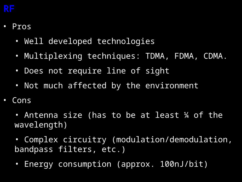
RF
• Pros
• Well developed technologies
• Multiplexing techniques: TDMA, FDMA, CDMA.
• Does not require line of sight
• Not much affected by the environment
• Cons
• Antenna size (has to be at least ¼ of the wavelength)
• Complex circuitry (modulation/demodulation, bandpass filters, etc.)
• Energy consumption (approx. 100nJ/bit)

Optical
• Pros
• Low energy consumption (<1nJ/bit)
• High data rates
• Small aperture, very directional (localization)
• Spatial division multiplexing
• Cons
• Very directional
• Line of sight
• Atmospheric turbulence, weather and environmental conditions dependent
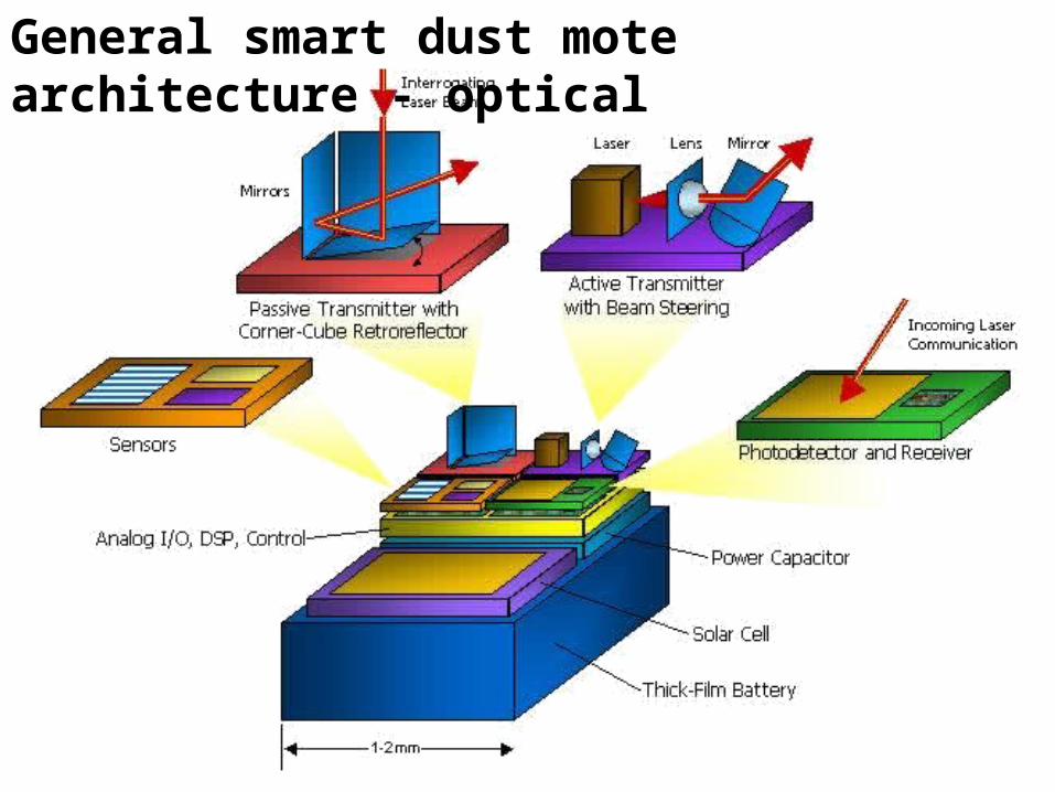
General smart dust mote architecture - optical

MEMs controlled corner cube retro-reflector
• Perfectly aligned corner cube reflects light at the exact same direction of incidence
• MEMs control of one of the corner cube side’s alignment enables modulation
• Energy consumption of about 1pJ/bit @ 1kb/sec
• Range up to 1km
UC Berkeley

Smart dust active transmitter• Incorporates a laser, lens and a MEM steering mirror
• 1mrad transmission
• Data rate of approx. 5Mb/sec
• Energy consumption depends on distance and detector size
DistanceDetector
areaEnergy
consumption
5m 0.1mm2 ~20pJ/bit
5km 1cm2 ~10nJ/bit
500km 1m2 ~25nJ/bit
1mW at 1mrad laser is 40 times brighter than 100W light bulb
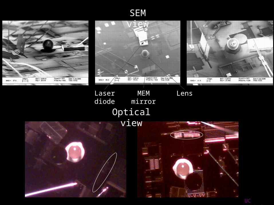
SEM view
Laser diode LensMEM mirror
Optical view
UC Berkeley

Experimental results
• Beam steering at kHz rates
• Steering in approx 1str ≈ 60X 60
300m Link test5.2 km Berkeley Marina15.3 km Coit Tower
14W laser 8mW laser

The base station
• Hand held
• Binoculars
• Palm
• Cell phone
• Laptop computer
• Command center
• Unmanned vehicle (land, sea, air)
• Autonomous systems
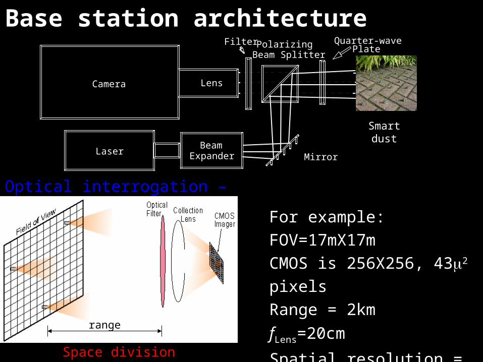
Base station architecture
Optical interrogation – principles of operation
Camera Lens
Beam Mirror
Polarizing Beam Splitter
Quarter-wavePlate
Filter
Laser Expander
Smart dust
For example:
FOV=17mX17m
CMOS is 256X256, 432 pixels
Range = 2km
fLens=20cm
Spatial resolution = 6.6cm2 range
Space division multiplexing

Airborne base station example
UC Berkeley and MLB Co.

Challenges for mobile networking for smart dust
• Line of sight requirement
• Link directionality
• Parallel readout and cross talk
• Trade-offs
• Revisit rates

Line of sight requirement
• Optical communication requires photons from the transmitter reach the receiver – photons travel in straight lines
• Line of sight is not the only way of making the photons arrive at a desired location:
• Diffuse reflections – low energy, wide spread (the entire FOV) and low contrast with the environment (especially with interrogating beam)
• Non fixed smart dust systems - line of sight could be achieved intermittently
• Ad hoc multi-hop routing
Cannot work with passive communication, very small SNR
Latency
AlgorithmsLatencyReliability

Link directionality
Passive links• A corner cube retro-reflector angle of acceptance is 10-20
• Placing multiple corner cubes
• Placing the corner cube and the receiver on a MEM mount – signal maximization
• Increase mote density – high probability for communication with at least some motes in the area of interest
General
• Motes are unaware of neighbors location
• Base station can disseminate location information to motes

Active links
• Mote receiver is omnidirectional within a hemisphere
• Enables mote attention without aiming
• No source identification
• Making the receiver directional (by adding a lens) and connecting its directionality to the transmitter will enable communication automatically to the source
• Requires aiming
• Solved by increasing the density of motes
• In a static system, identification could be saved in mote memory
• Difference between receiver and transmitter angular spreads leads to non-reciprocal linking

Parallel readout and crosstalk• The network architecture of smart dust enables space division multiplexing in the base station
• There are as many channels as there are pixels in the CMOS camera of the base station
• If the interrogating beam is divergent enough several motes could be ready simultaneously
• A base station will not distinguish between motes in the same space equivalent pixel
• TDMA could be incorporated in the architecture – modulation of the interrogating beam could establish a clock for synchronization
• Demand access method (as in cellular and satellite networks) could be implemented as well – a mote sends an active short pulse to the base station will receive attention by the interrogation beam of the base station

Trade-offs
SNR – signal to noise ratio, governs the probability for bit error
Pt – average transmitter power
A – receiver area
N0 – receiver inherent noise
B – bit rate
r – the distance between the transmitter and receiver
- beam divergence

Revisit rate
• Revisit rate should be application specific
• Use of AI – learning system
• Frequent revisits to areas in which changes happen most rapidly
• Could be based on human judgment or automatic
• Could be based on the demand access method

What we have today
www.xbow.com www.dust-inc.com
• Different markets• Airborne systems – monitoring, camera stability, unmanned…• Marine• Land vehicles• Environment
• Mote price ~100$• Kit price (8-12 motes) ~ 2000$
• Building management• Industrial monitoring• Security

Would like to have capabilities (a partial list)
• Miniaturization of available smart dust and extreme price reduction
• Possibility of optical pre-processing and optical circuits
• Incorporate the concept of smart dust societies – integration of different types of smart dust
• Requires more robust network protocols
• Requires better definition of mote task
• Enables complex systems easy distribution
• Enables smaller and cheaper motes

• Multi wavelength VCSEL arrays will enable smart dust WDM
capabilities
• Beam quality control (divergence) – for easier scanning
• Electro-optic instead of MEMs
• Higher bit rate (will be required for very large networks)
• Lower energy (about 20pJ/bit @ 10Mb/sec)
• Active smart dust – interfaces, robotic capabilities and motion
Rocket chip
UCSD

References• JM Kahn, RH Katz & KSJ Pister, “Emerging challenges: mobile networking for smart dust”, J. of Comm. and Net. 2 pp.188-196 (2000)
• Y Song, “Optical Communication Systems for Smart Dust”, M.Sc. Thesis, Virginia polytechnic institute and state university, 2002
• The following urls:• http://www.darpa.mil/•http://robotics.eecs.berkeley.edu/~pister/SmartDust/• http://www-bsac.eecs.berkeley.edu/archive/users/warneke-brett/SmartDust/index.html• http://www.xbow.com/• http://www.dust-inc.com/• http://chem-faculty.ucsd.edu/sailor/research/highlights.html• http://www.nanotech-now.com/smartdust.htm
