embedded multi-core systems for mixed criticality … call 2013, project 621429 emc² d10.3 first...
TRANSCRIPT

ARTEMIS Call 2013, project 621429 EMC²
D10.3 First prototype application and the description of the conceptual architecture Page 1 of 30
Embedded multi-core systems for
mixed criticality applications
in dynamic and changeable real-time environments
Project Acronym:
EMC²
Grant agreement no: 621429
Deliverable
no. and title D10.3 First prototype application and the description
of the conceptual architecture
Work package WP10 Industrial Applications and Logistics
Task / Use Case T10.1
T10.2
T10.3
T10.4
UC_Drives and electric motors in industrial applications
UC_Identification and authentication
UC_Tracking
UC_Manufacturing quality control by 3D inspection
Lead contractor Infineon Technologies AG
Dr. Werner Weber, mailto:[email protected]
Deliverable
responsible
Danfoss Power Electronics A/S
Dr. Juha Kuusela, mailto: [email protected]
Version number v1.0
Date 05/12/2015
Status Final
Dissemination level PU
Copyright: EMC2 Project Consortium, 2015

ARTEMIS Call 2013, project 621429 EMC²
D10.3 First prototype application and the description of the conceptual architecture Page 2 of 30
Authors
Partici-
pant
no.
Part.
short
name
Author name Chapter(s)
05A Danfoss Juha Kuusela T10.1 – UC_Drives and Electric Motors in Industrial
Applications
05B DTU
01O FhG
04A BUT
09B UTRC Stylianos Basagiannis T10.1 - Description of model based motor control
01R NXP Kiran Shekhar T10.2 – UC_Identification and Authentication
15R AMBAR Roberto García
Esaú Turrado
T10.3 – UC_Tracking
15Q ITI Sergio Sáez
Javier Cano
T10.4 – UC_Manufacturing Quality Control by 3D
Inspection
09C Lero
Document History
Version Date Author name Reason
v0.1 18/08/2015 Juha Kuusela Initial structure
v0.2 17/11/2015 Juha Kuusela Description of Use Case 10.1 demonstrator
v0.3 17/11/2015 Kiran Shekhar Description of Use Case 10.2 Identification and
Authentication
v0.4 18/11/2015 Kiran Shekhar Review
v0.5 20/11/2015 Sergio Sáez
Javier Cano
Description of Use Case 10.4 Manufacturing Quality
Control by 3D Inspection
v0.6 26/11/2015 Juha Kuusela Page layout, references, title pages
v0.7 26/11/2015 Roberto García
Esaú Turrado
Description of Use Case 10.3 Tracking
v0.8 30/11/2015 Juha Kuusela Conclusion
v0.9 4/12/2015 Juha Kuusela Comments by Sara Díez del Valle Garzón
v1.0 4/12/2015 Stylianos Basagiannis Description of model based motor control
5/12/2015 Alfred Hoess Final review, final editing and formatting, deliverable
submission
ARTEMIS Call 2013, project 621429 EMC²
D10.3 First prototype application and the description of the conceptual architecture Page 3 of 30
Executive Summary
The ultimate objective of the EMC2 project (and WP10 in that context) is to establish Multi-core
technology in all relevant Embedded Systems domains. The embedded systems segment is currently
going through a disruptive innovation process. Different kinds of systems are connected to each other,
boundaries of application domains are alleviated and interoperability plays an increasing role. Formerly
closed systems are forced to be opened up. As Multi-core and Many-core processors increase their
visibility in the embedded systems domain, their exploitation for critical and real-time applications is
presently too slow, inefficient and expensive.
This development leads to the fact that system components that have previously been embedded and
executed in separate hardware can now share the same hardware, thus resulting in new challenges for
safety requirements. At the same time multiple cores potentially allow different types of functions to stay
separated where necessary.
This document gives a brief description of first prototypes and detailed design of all the four use cases of
WP10 within the industrial domain (or Living Lab 10 for Industrial manufacturing & logistics). The four
use cases represent four different industrial applications: (1) Variable Speed Drives in Industrial
Applications, (2) Identification and Authentication, (3) Tracking and (4) Manufacturing Quality Control
by 3D Inspection.
The development work has been based on the requirements set earlier. In each case we have been able to
address many but not all of the requirements. In the development we have applied some of the
technologies developed in the technical work packages.
ARTEMIS Call 2013, project 621429 EMC²
D10.3 First prototype application and the description of the conceptual architecture Page 4 of 30
Table of contents
1. Introduction ............................................................................................................................................................. 6
1.1 Objective and scope of the document ............................................................................................................. 6
1.2 Structure of the deliverable report .................................................................................................................. 6
2. T10.1 – UC_Drives and Electric Motors in Industrial Applications ....................................................................... 6
2.1 Description of the first prototype for the Drives Use Case ............................................................................. 6
2.2 Description of the conceptual architecture ..................................................................................................... 9
2.3 Properties of the prototype and relation to technical WPs ............................................................................ 13
3. T10.2 – UC_Identification and Authentication ..................................................................................................... 14
3.1 Multi-secure-element core handler as root of trust ....................................................................................... 14
3.2 Detailed design of the first prototype ........................................................................................................... 17
4. T10.3 – UC_Tracking ............................................................................................................................................ 20
4.1 Tracking devices........................................................................................................................................... 20
4.2 Concentrator ................................................................................................................................................. 21
3.3 Central server ............................................................................................................................................... 22
4.3 Overview of contributions from technical WP’s .......................................................................................... 23
4.4 Requirements ................................................................................................................................................ 23
5. T10.4 – UC_Manufacturing Quality Control by 3D Inspection ............................................................................ 23
5.1 Description of the prototype ......................................................................................................................... 23
5.1.1 Detailed design of the first prototype ............................................................................................... 24
5.2 Description of the conceptual architecture ................................................................................................... 25
5.3 Properties of the prototype ........................................................................................................................... 26
5.4 Overview of contributions from technical WP’s .......................................................................................... 27
5.5 Requirements ................................................................................................................................................ 28
6. Conclusions ........................................................................................................................................................... 28
7. References ............................................................................................................................................................. 30
ARTEMIS Call 2013, project 621429 EMC²
D10.3 First prototype application and the description of the conceptual architecture Page 5 of 30
List of Figures
Figure 1 - Functional elements of a VSD ...................................................................................................................... 6 Figure 2 - Prototype hardware ....................................................................................................................................... 7 Figure 3 - Deployment of the VSD demonstrator ......................................................................................................... 8 Figure 4 – Test set-up for fully model driven control ................................................................................................... 9 Figure 5 - Control electronic concept of the UC1 demonstrator ................................................................................... 9 Figure 6 - Layered software architecture .................................................................................................................... 10 Figure 7 - STO functionality bypassing the software layers ....................................................................................... 11 Figure 8 - Block diagram in fully model driven study ................................................................................................ 11 Figure 9 - Models for the FPGA-HW implementation ............................................................................................... 12 Figure 10 - Models for the SW implementation in the ARM cores ............................................................................ 12 Figure 11 - Task partition and mapping ...................................................................................................................... 13 Figure 12 - Block Diagram of Multi-Secure-Element Root of Trust connected to Network ...................................... 15 Figure 13 - Block diagram of hierarchical multi secure element root of trust interfaced to host network .................. 16 Figure 14 - First prototype representation (top), Off-the-shelf implementation (bottom left) and development board
(bottom right) .......................................................................................................................................... 17 Figure 15 - One sided Authentication use case ........................................................................................................... 18 Figure 16 - Mutual authentication use case ................................................................................................................. 19 Figure 17 - Main Subsystems ...................................................................................................................................... 20 Figure 18 - ZigBee/6LowPan monitoring nodes ......................................................................................................... 21 Figure 19 - Gateway modular design .......................................................................................................................... 22 Figure 20 – Flow and tasks for 3D reconstruction process modeled with “art2kitekt” ............................................... 27 Figure 21 – Parallel execution diagram of the tasks.................................................................................................... 27

ARTEMIS Call 2013, project 621429 EMC²
D10.3 First prototype application and the description of the conceptual architecture Page 6 of 30
1. Introduction
1.1 Objective and scope of the document
This document describes the conceptual architecture of each use case. This deliverable includes also the
description of the corresponding prototypes for each of these use cases.
1.2 Structure of the deliverable report
The document is organized as follows: the sections 2, 3, 4 and 5 present the four use cases in WP10. Each
of the sections provides a description of the particular use case and key requirements, an overview of the
conceptual architecture used to address those requirements with references to contributions from the
technical work packages inspiring the conceptual architecture. Finally, Section 6 concludes the
deliverable, and Section 7 lists the references.
2. T10.1 – UC_Drives and Electric Motors in Industrial Applications
2.1 Description of the first prototype for the Drives Use Case
Industrial processes place strict requirements on the automation systems. Electric motors and Variable
Speed Drives (VSD) that operate these motors – often just called “drives” – are the backbone of industrial
automation systems. A typical industrial application is automated and controlled using multiple devices.
In general, each such device has one or more mechanical parts, which are driven by an electric motor via
a transmission system. VSD can give precise control over speed, torque, and position, which can then be
matched to the process under control, yielding energy savings and removing the need for complicated
mechanical control devices.
It is typical that in addition to safety requirements – a characteristic of numerous automation systems –
VSDs must satisfy other quality related requirements. For instance a crane manufacturer must also fulfill
performance (e.g. vertical speed), user comfort (e.g. smooth acceleration), customer expectations (e.g.
ability to serve 50 meters vertical height), and reliability (e.g. 2 hours maximum maintenance time per
year) requirements.
Motor
Electric Power
Modulation and Protection
Diagnostic Functions
Sensor
Basic Motor Control
Application Control Program
Power Section
Communications and I/O
Exte
rnal
Sig
nal
s
Embedded Control System
Control
current feedbackspeed feedback
Figure 1 - Functional elements of a VSD
A VSD (see Figure 1) follows a standard high-level design, which includes an Embedded Control System
that: communicates with external controllers via the External Signals; actuates the Motor via the Power
Section, to fulfil the application requirements and requests received via External Signals; and finally, uses
ARTEMIS Call 2013, project 621429 EMC²
D10.3 First prototype application and the description of the conceptual architecture Page 7 of 30
current and speed feedbacks from Sensors to the control system. The functional elements of the
Embedded Control System are divided into two groups: safety-related functions, and the VSD application
itself. Therefore the embedded controller encompasses mixed criticality ranging from Safety Integrity
Level 1 to 3 (SIL1-3). The safety-related functions consist of drive-based safety functions defined in IEC
61800-5-2, and protection functions defined in IEC 61800-5-1, UL 508C, and UL 61800-5-1. The
application control could be split into two domains the Application Control Program (ACP), and Basic
Motor Control (BMC). The ACP typically models the application, e.g., conveyer belt, fan, pump, etc.
Depending on the application being controlled, the ACP has varying real-time requirements ranging from
soft to hard real-time. The BMC is responsible for handling the operation of the electric motor with hard
real-time constraints.
VSDs are typically implemented on heterogeneous hardware consisting of dedicated processing elements,
like MCUs, DSPs and FPGAs. A commercial off-the-shelf System-on-Chip solution is a suitable VSD
hardware platform, as it provides the necessary processing performance with high-level integration
resulting in lower costs.
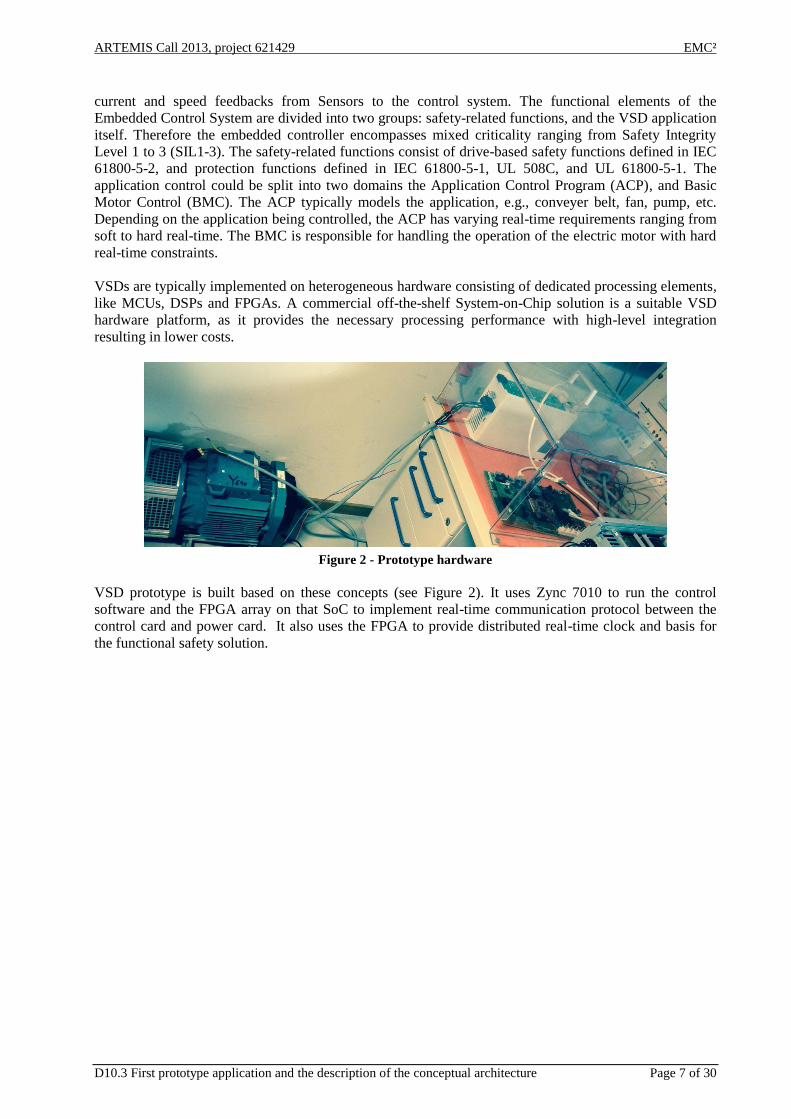
Figure 2 - Prototype hardware
VSD prototype is built based on these concepts (see Figure 2). It uses Zync 7010 to run the control
software and the FPGA array on that SoC to implement real-time communication protocol between the
control card and power card. It also uses the FPGA to provide distributed real-time clock and basis for
the functional safety solution.
ARTEMIS Call 2013, project 621429 EMC²
D10.3 First prototype application and the description of the conceptual architecture Page 8 of 30
Interface Board
MicroZed board
BSP
Powerbus (FPGA)
Power card
Hoist
M
Powerbus (FPGA)
FPGA interface
Middleware
HAL/OSAL/Network
powerbus
Intel Wifi Chip
SPI (FPGA) UART
Application running on middleware
Middleware services
Wifi protocol handler
Hoist applicationS1015 Motor
Control
Iphone
PC
Iphone App
Console interface
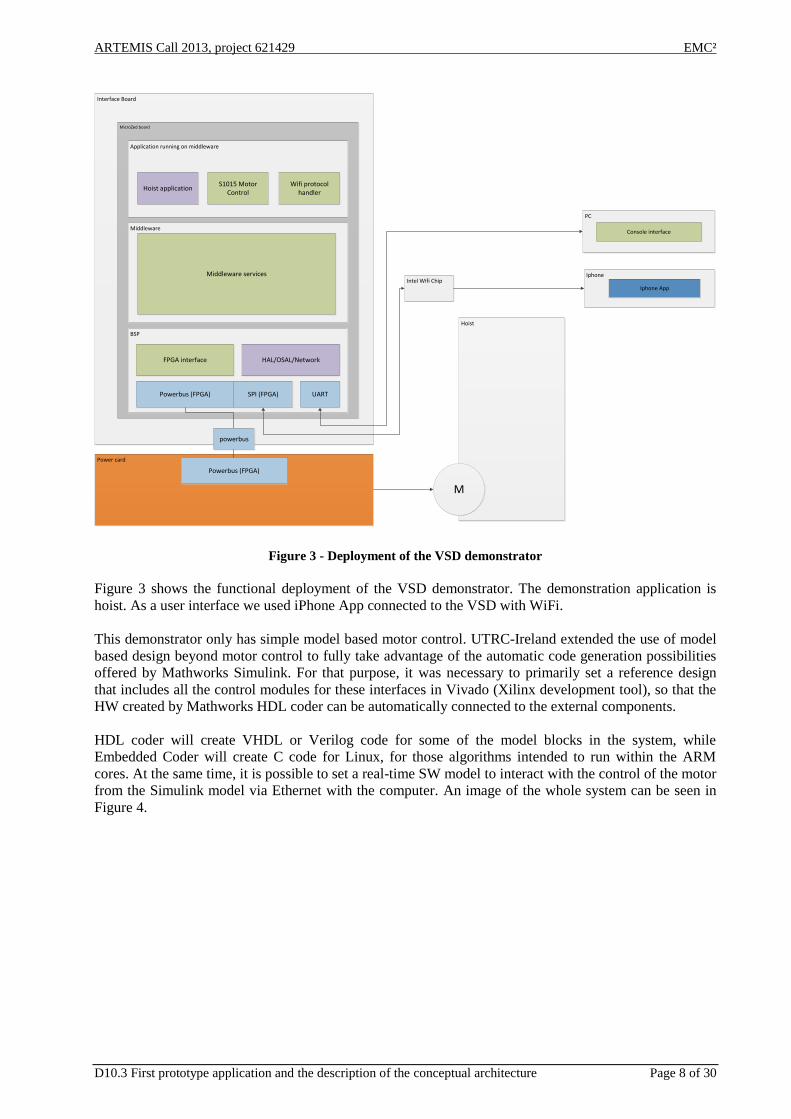
Figure 3 - Deployment of the VSD demonstrator
Figure 3 shows the functional deployment of the VSD demonstrator. The demonstration application is
hoist. As a user interface we used iPhone App connected to the VSD with WiFi.
This demonstrator only has simple model based motor control. UTRC-Ireland extended the use of model
based design beyond motor control to fully take advantage of the automatic code generation possibilities
offered by Mathworks Simulink. For that purpose, it was necessary to primarily set a reference design
that includes all the control modules for these interfaces in Vivado (Xilinx development tool), so that the
HW created by Mathworks HDL coder can be automatically connected to the external components.
HDL coder will create VHDL or Verilog code for some of the model blocks in the system, while
Embedded Coder will create C code for Linux, for those algorithms intended to run within the ARM
cores. At the same time, it is possible to set a real-time SW model to interact with the control of the motor
from the Simulink model via Ethernet with the computer. An image of the whole system can be seen in
Figure 4.
ARTEMIS Call 2013, project 621429 EMC²
D10.3 First prototype application and the description of the conceptual architecture Page 9 of 30
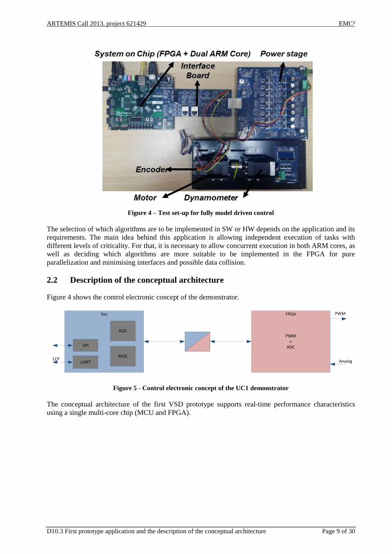
Figure 4 – Test set-up for fully model driven control
The selection of which algorithms are to be implemented in SW or HW depends on the application and its
requirements. The main idea behind this application is allowing independent execution of tasks with
different levels of criticality. For that, it is necessary to allow concurrent execution in both ARM cores, as
well as deciding which algorithms are more suitable to be implemented in the FPGA for pure
parallelization and minimising interfaces and possible data collision.
2.2 Description of the conceptual architecture
Figure 4 shows the control electronic concept of the demonstrator.
Figure 5 - Control electronic concept of the UC1 demonstrator
The conceptual architecture of the first VSD prototype supports real-time performance characteristics
using a single multi-core chip (MCU and FPGA).
PWM+
ADC
AOC
MOC
SPI
UARTLCP
Soc PWM
Analog
FPGA
ARTEMIS Call 2013, project 621429 EMC²
D10.3 First prototype application and the description of the conceptual architecture Page 10 of 30
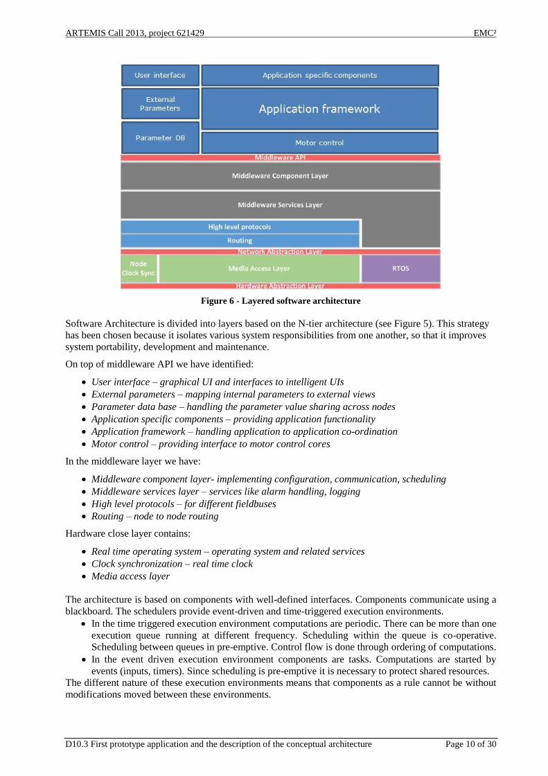
Figure 6 - Layered software architecture
Software Architecture is divided into layers based on the N-tier architecture (see Figure 5). This strategy
has been chosen because it isolates various system responsibilities from one another, so that it improves
system portability, development and maintenance.
On top of middleware API we have identified:
User interface – graphical UI and interfaces to intelligent UIs
External parameters – mapping internal parameters to external views
Parameter data base – handling the parameter value sharing across nodes
Application specific components – providing application functionality
Application framework – handling application to application co-ordination
Motor control – providing interface to motor control cores
In the middleware layer we have:
Middleware component layer- implementing configuration, communication, scheduling
Middleware services layer – services like alarm handling, logging
High level protocols – for different fieldbuses
Routing – node to node routing
Hardware close layer contains:
Real time operating system – operating system and related services
Clock synchronization – real time clock
Media access layer
The architecture is based on components with well-defined interfaces. Components communicate using a
blackboard. The schedulers provide event-driven and time-triggered execution environments.
In the time triggered execution environment computations are periodic. There can be more than one
execution queue running at different frequency. Scheduling within the queue is co-operative.
Scheduling between queues in pre-emptive. Control flow is done through ordering of computations.
In the event driven execution environment components are tasks. Computations are started by
events (inputs, timers). Since scheduling is pre-emptive it is necessary to protect shared resources.
The different nature of these execution environments means that components as a rule cannot be without
modifications moved between these environments.

ARTEMIS Call 2013, project 621429 EMC²
D10.3 First prototype application and the description of the conceptual architecture Page 11 of 30
The integration of Safe Torque Off is relatively straight forward (see Figure 6) as it is possible to bypass
the software layers to reach SIL3, PLe, Cat ¾ solutions. For the next demonstrator we are working for a
concept that would handle the required mixed criticality in the software layers.
Figure 7 - STO functionality bypassing the software layers
This architecture also demonstrates declarative components and flexible deployment. Binding of
functionality takes place during the system installation or at runtime. In this prototype there is no tool
support for building such a drive configuration.
This prototype uses a simple model driven motor control but does not completely fulfill the requirements
like torque control (Requirement 05A-4_1_1) or speed feedback (requirement 05A-4_1_2). UTRC
studied a possibility to bring model based development further and use model driven design also for
FPGA. The processing architecture also in this case consists of 2 ARM cores and an FPGA fabric. One of
the ARM cores will be in charge of running the control of the operation mode of the motor, as well as the
speed control algorithm. The other core will run some Prognostic and Health Management (PHM) control
algorithms. On the FPGA side, data acquisition, encoder data transformation, current control and PWM
generation will be in included. Some of the PHM algorithms will need some data pre-processing. This
PHM extra processing tasks, such as a voting systems, will be included in the FPGA to take advantage of
parallelization. The block diagram of the system is shown in Figure 8.
Figure 8 - Block diagram in fully model driven study

ARTEMIS Call 2013, project 621429 EMC²
D10.3 First prototype application and the description of the conceptual architecture Page 12 of 30
Models were developed in Simulink both for FPGA (Figure 9) and for the two ARM cores (Figure 10).
Figure 9 - Models for the FPGA-HW implementation
Figure 10 - Models for the SW implementation in the ARM cores
In order to specify concurrency within the tasks scheduled in SW, Simulink allows a task partition and
mapping to allow concurrency. Figure 11 shows the different tasks marked with colored blocks.

ARTEMIS Call 2013, project 621429 EMC²
D10.3 First prototype application and the description of the conceptual architecture Page 13 of 30
Figure 11 - Task partition and mapping
The general workflow followed for the design and prototyping is:
1. Build the models of the desired algorithms in Simulink using models of the motor and loads.
2. Generate a reference design for the FPGA system to include those HW parts that will not be defined
in Simulink, like for instance, interfaces.
3. Simulate the models choosing a configuration as close to reality as possible.
4. Select weather they will be implemented in SW or HW. Take into account data types, algebraic loops,
fix point and mathematical operations.
5. Simulate again taking the previous into consideration.
6. Select, apart from the SW/HW partition, the desired partition and mapping of the SW tasks so they
can be executed in a concurrent way. Be careful with data transmission among tasks.
7. Use HDL Coder and Embedded Coder to generate both C and VHDL code.
8. Use Xilinx SDK to compile the C code for Linux and Xilinx Vivado to synthesize the VHDL code
and generate the bit stream configuration file.
9. Generate a model for the real time interaction with the motor.
This study demonstrated that it is possible to support fast prototyping of motor control systems in
heterogeneous multiprocessing environments.
2.3 Properties of the prototype and relation to technical WPs
The goal of this prototype is to verify the conceptual architecture both for HW and SW. It shows that the
real-time communication works with the middleware. The correctness of the drive operation depends on
the timely execution of its functions (05A-1_0_4). The demonstrator shows that we have a solution on a
predictability supporting this requirement (related to WP3). Our solution is made so that we will be able
to use OSSS-MC technology developed by OFFIS in WP2 tasks T2.2 and T2.3.

ARTEMIS Call 2013, project 621429 EMC²
D10.3 First prototype application and the description of the conceptual architecture Page 14 of 30
The requirement 05A-1_2_0 specifies parallelism in software but also in hardware using FPGAs. The
demonstrator shows that functionality can be deployed for both cores and the FPGA. Development also
showed that FPGA software can be developed flexibly and iteratively. Tool support is based on WP2.
IEC 61800-5-2 specifies the designated safety functions (05A-1_1_1) that are relevant to variable speed
drives for the industrial domain. These safety functions and their constraints have to be taken into account
when architecting the drive. In this use case, the safety function Safe Torque Off (STO) is integrated as
the standard safety function. The STO (05A-4_3_1_0) ensures that power which could otherwise cause a
rotation of the motor is not applied.
The requirement 05A-1_1_3 specifies that temporal and spatial separation between software elements of
different criticality shall be achieved, allowing these elements to co-exist on the same device such that the
non-safety related functions can be modified without impacting the certified safety related functions. This
requirement is not satisfied in this prototype. We are working to expand the conceptual architecture for
this mixed criticality requirement (05A-1_1_4) using the modular safety framework developed in WP6.
The requirement 05A-1_0_3 specifies that the drive function binding can be performed at different times,
allowing a certain degree of adaptation to the system. This architecture demonstrates declarative
components and flexible deployment. Binding of functionality takes place during the system installation
or at runtime. Different deployments will be tried out for the next demonstrator.
The prototype has model based motor control core (based on the techniques from WP5) but this one does
not have torque control (Requirement 05A-4_1_1) and it does not have speed feedback (requirement
05A-4_1_2). Primitive protection functions have been implemented but the use of feedback as indicated
by requirement 05A-4_1_3 is very limited.
Prototypes are set to be evaluated within WP5 in order to evaluate interoperability of systems and tools
used towards traceability of requirements, as well as within WP6 for evaluating safety (09B-4_6_0, 09B-
4_6_2). Developed models will be analyzed within framework developed in Task 5.3 where transversal
services enabled by tool adaptors will allow model results to be assessed and traced according to
prototype requirements (09B-4_6_0, 09B-4_6_1, 09B-4_6_2). Safety evaluation (WP6) will be primarily
based on adopting OSLC solutions for seamless and semantically proven communication between
different model-based design tools which will strengthen the certification credit towards the requirement
09B-4_6_3.
To summarize, this demonstrates that multi-core processors can be used to launch different control levels
on different cores and FPGA with respect to criticality and safety aspects. It addresses many but not all of
the requirements set by [D10.1].
3. T10.2 – UC_Identification and Authentication
3.1 Multi-secure-element core handler as root of trust
Security & connectivity are enablers of the modern day technology revolution. With advancements in
wireless network infrastructure, more & more devices are connected to each other and hence security is
ubiquitous in 21st century home (Smart Home/Internet of Things) or industry (Smart Factory/Industry 4.0)
domain to prevent unauthorized access, establish identity of communicating partners and create secure
channel between them.
Based on costs, scalability & complexity security handled using hardware or software or a combination of
both. Large networks spread across at different geographical locations like World Wide Web or Internet
have dedicated security infrastructure (Public Key Infrastructure or PKI) and SW protocols (i.e. Transport

ARTEMIS Call 2013, project 621429 EMC²
D10.3 First prototype application and the description of the conceptual architecture Page 15 of 30
Layer Security or TLS & Secure Socket Layer or SSL) that handle secure connection & communication.
However for smaller/simple networks & subsystems, these mechanisms would be a lot of overhead and
too costly on resources & power. A secure element (SE) or crypto co-processor could be thought of for
handling the security requirements for small-scale networks. In addition, a dedicated hardware secure
element or co-processor
removes security related tasks from main processor (more time & resources for core activities)
acts as a trusted platform module (TPM) that provide secure environment for processing & saving
security requests & parameters
is immune to software manipulations or implementation flaws/bugs in whole system
is tamperproof and provides resistance to side channel attacks etc.
However as the network size (number of clients) and complexity (multicast & broadcast) grows, it is
impractical to connect an SE to each client. It makes sense to group multiple secure elements into a single
security node that provides a multi-core root of trust service to all networked clients. It improves the
deployment efficiency of individual SEs and reduces component costs. These are in line with objectives
of EMC2 (i.e. A multi secure element core security solution for mixed criticality applications in a cross
domain, dynamic, changeable real-time embedded environment). This multi secure element core handler
(MSEH) provides security as a service that are described in detail below [REQ_01R_NXP_003].
Confidentiality using message encryption/decryption with symmetric (AES) or asymmetric (RSA,
ECC) cryptography protocols (i.e.no eavesdropping on the channel)
Message authentication to prove the identity of sender to receiver (Digital certificates
[REQ_01R_NXP_005])
Message integrity which ensures that message is not tampered on the channel (MAC or message
authentication codes)
Non-repudiation or denial of sending a message by client on the network (Digital
signature[REQ_01R_NXP_005])
A functional block diagram of such a network with root of trust is shown in Figure 12.
Figure 12 - Block Diagram of Multi-Secure-Element Root of Trust connected to Network
The service oriented architecture (SoA) of MSEH abstracts the multiple interconnected SEs to the outside
network as a virtual (& single) security device that is interfaced to host using standard communication
protocols. It plays a role of networked security module [REQ_01R_NXP_001] with plug & play
functionality. It handles multiple security requests of different kinds from the clients on the network.
Individual SEs can be dynamically reconfigured to provide different security services at runtime based on
the type & number of requests. This increases the utilization factor of individual SE as per the load. The
MSEH increases the security service throughput of the system with multiple SEs servicing requests in
parallel [REQ_01R_NXP_004]. The hardware abstraction and redundancy by reconfiguration eases the
ARTEMIS Call 2013, project 621429 EMC²
D10.3 First prototype application and the description of the conceptual architecture Page 16 of 30
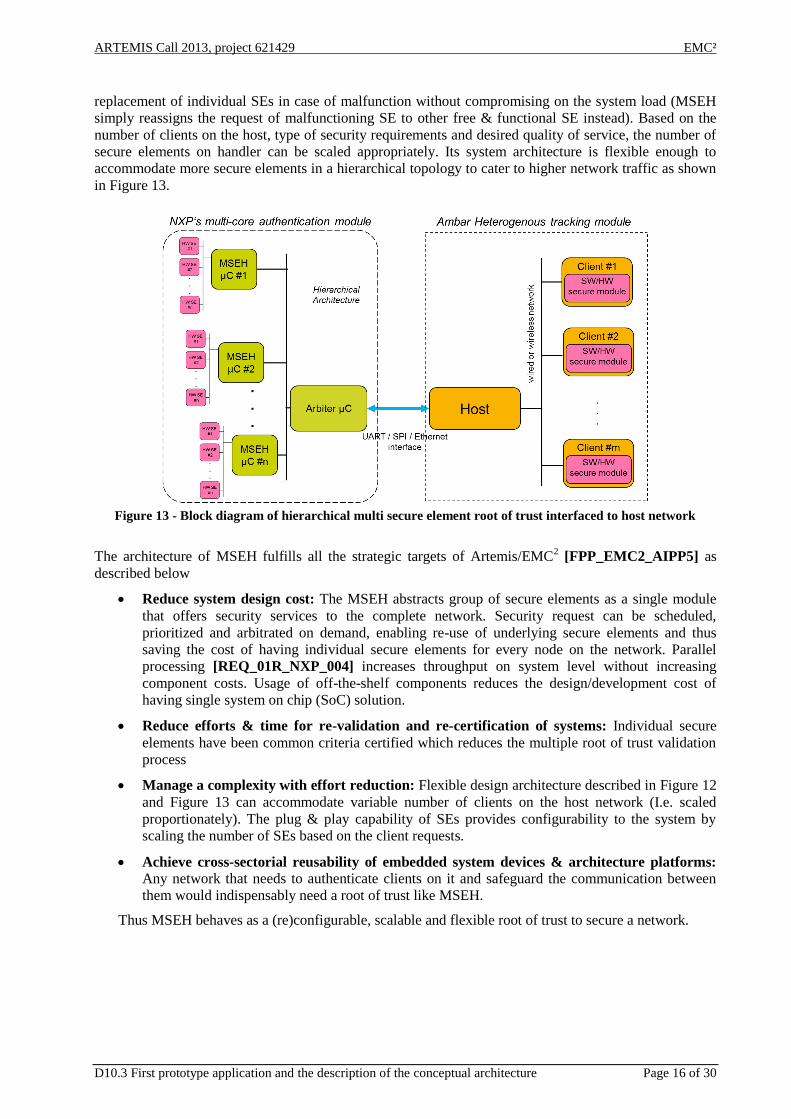
replacement of individual SEs in case of malfunction without compromising on the system load (MSEH
simply reassigns the request of malfunctioning SE to other free & functional SE instead). Based on the
number of clients on the host, type of security requirements and desired quality of service, the number of
secure elements on handler can be scaled appropriately. Its system architecture is flexible enough to
accommodate more secure elements in a hierarchical topology to cater to higher network traffic as shown
in Figure 13.
Figure 13 - Block diagram of hierarchical multi secure element root of trust interfaced to host network
The architecture of MSEH fulfills all the strategic targets of Artemis/EMC2 [FPP_EMC2_AIPP5] as
described below
Reduce system design cost: The MSEH abstracts group of secure elements as a single module
that offers security services to the complete network. Security request can be scheduled,
prioritized and arbitrated on demand, enabling re-use of underlying secure elements and thus
saving the cost of having individual secure elements for every node on the network. Parallel
processing [REQ_01R_NXP_004] increases throughput on system level without increasing
component costs. Usage of off-the-shelf components reduces the design/development cost of
having single system on chip (SoC) solution.
Reduce efforts & time for re-validation and re-certification of systems: Individual secure
elements have been common criteria certified which reduces the multiple root of trust validation
process
Manage a complexity with effort reduction: Flexible design architecture described in Figure 12
and Figure 13 can accommodate variable number of clients on the host network (I.e. scaled
proportionately). The plug & play capability of SEs provides configurability to the system by
scaling the number of SEs based on the client requests.
Achieve cross-sectorial reusability of embedded system devices & architecture platforms: Any network that needs to authenticate clients on it and safeguard the communication between
them would indispensably need a root of trust like MSEH.
Thus MSEH behaves as a (re)configurable, scalable and flexible root of trust to secure a network.

ARTEMIS Call 2013, project 621429 EMC²
D10.3 First prototype application and the description of the conceptual architecture Page 17 of 30
3.2 Detailed design of the first prototype
The first prototype is designed as a proof of concept using off the shelf components to demonstrate the
functionality of multi-secure element handler. A block diagram representation of the prototype is given in
Figure 14.
Figure 14 - First prototype representation (top), Off-the-shelf implementation (bottom left) and development
board (bottom right)
A brief description about the components of the test setup is given below
MSE Handler: It is a generic microcontroller (ARM Cortex M3) that interfaces multiple secure
elements on one side and Test Bench (or Host in actual deployment environment) on the other side
using standard serial protocols. It acts as a scheduler that queues the multiple asynchronous security
requests of the networked clients connected to the host. MSEH arbitrates the requests, assigns priority
and allocates suitable secure element for execution based on the type of service demanded by clients.
It configures (& reconfigures) individual SEs to service the request based on its type (increased
utilization factor) and offers parallel processing of requests (increased throughput). It simply routes
the client’s request to SE and doesn’t perform any crypto operations by itself. It supports all standard
communication interfaces like USART, SPI, Ethernet, USB etc. to the host and hence can be
connected to any decentralized (free) bus of it [REQ_01R_NXP_001].
Secure element: It is a Common Criteria certified NXP secure crypto controller that supports
standard crypto operations like authentication, encryption/decryption, digital signatures (SHA1,
SHA224, SHA256 & MD5), certificates (X.509 based & PKCS#15 format) and secure storage. It
finds application mainly in smartcard domains for banking, e-Gov, transportation, loyalty, health-
insurance cards, smart-meters and identity sectors. It has asymmetric or PKI coprocessors (RSA up to
2048 bit keys & ECC over GF (p) up to 320 bit keys) [REQ_01R_NXP_005] & symmetric
coprocessors (SEED, 2/3 key triple-DES & 128/192/256 bit keys AES {in ECB, CBC & CBC-MAC
modes}) [REQ_01R_NXP_006] and compliant with JavaCard v3.0.1 & Global platform specs. In

ARTEMIS Call 2013, project 621429 EMC²
D10.3 First prototype application and the description of the conceptual architecture Page 18 of 30
addition, it has true random number generator & supports CRC calculations. Its powerful
cryptographic core is robust against attacks and possesses several countermeasures for protection of
device assets.
Test Bench: It simulates the host interface to the MSEH. It generates multiple client requests and
simulates different load scenarios with different timing constraints to emulate the real host
environment. It is a generic microcontroller that implements SPI protocol (it acts a SPI master and
MSEH as SPI slave) and performs cryptographic operations. In real world scenario the client should
either have a HW crypto co-processor attached to each of them or implement SW crypto stack (like
OpenSSL) individually to perform security handshake on MSEH on host. I.e. Every client node needs
to have a security counterpart [REQ_01R_NXP_002] of MSEH that establishes its identity to host
and eventually creates secure communication channel with host. The typical crypto operations on a
network simulated by test bench include client authentication, secure messaging between partners on
the network. They are briefly described below.
o Single sided authentication
Only one of the communication partners is authenticated in this case [REQ_01R_NXP_003]. It
is designed for scenarios, where there is one server or host in the network to which multiple
clients connect at random instance. The server is usually maintained by administrator and
considered secure & trustworthy [REQ_01R_NXP_005]. Hence only the client has to be
authenticated every time for a successful connection with server. This is the most likely use case
for EMC2 where the multi secure element handler together with the host behaves as admin and
wireless mobile tracking modules act as clients. Every client has to authenticate itself to host
(i.e. MSEH) using the protocol described in Figure 15.
Figure 15 - One sided Authentication use case
The authentication process is based on asymmetric key cryptography using RSA or ECC
protocols. It starts with client requesting host for a challenge (random number string or nonce).
The host replies with a nonce and request the client to sign it with his private key. The client
signs the nonce and attaches his public key certificate (it is issued by a central certificate
authority [CA]. The CA usually signs the client certificate using his private key. The CA acts as
ARTEMIS Call 2013, project 621429 EMC²
D10.3 First prototype application and the description of the conceptual architecture Page 19 of 30
trust anchor and his public key is known to all partners on the network). The host verifies
[REQ_01R_NXP_005] the certificate with CA public key and if valid proceeds to check the
signature of the nonce using the derived client’s public key to authenticate the client.
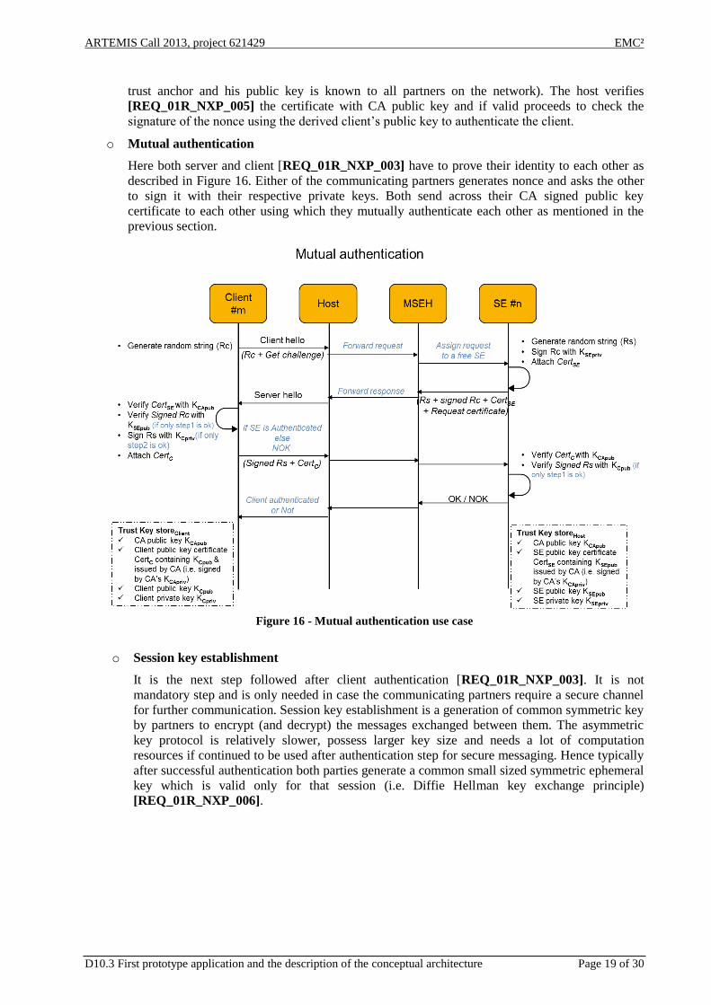
o Mutual authentication
Here both server and client [REQ_01R_NXP_003] have to prove their identity to each other as
described in Figure 16. Either of the communicating partners generates nonce and asks the other
to sign it with their respective private keys. Both send across their CA signed public key
certificate to each other using which they mutually authenticate each other as mentioned in the
previous section.
Figure 16 - Mutual authentication use case
o Session key establishment
It is the next step followed after client authentication [REQ_01R_NXP_003]. It is not
mandatory step and is only needed in case the communicating partners require a secure channel
for further communication. Session key establishment is a generation of common symmetric key
by partners to encrypt (and decrypt) the messages exchanged between them. The asymmetric
key protocol is relatively slower, possess larger key size and needs a lot of computation
resources if continued to be used after authentication step for secure messaging. Hence typically
after successful authentication both parties generate a common small sized symmetric ephemeral
key which is valid only for that session (i.e. Diffie Hellman key exchange principle)
[REQ_01R_NXP_006].

ARTEMIS Call 2013, project 621429 EMC²
D10.3 First prototype application and the description of the conceptual architecture Page 20 of 30
4. T10.3 – UC_Tracking
Solutions for tracking of resources are growing for different areas. These solutions are provided for
indoor industrial environments and global positioning scenarios based usually in a GPS infrastructure.
Depending on the environment area (indoor/outdoor) and complexity different approaches D10.1.
In this use case an indoor tracking solution based on multiple wireless standards is design and developed.
The system architecture defines three main subsystems, as stated in D10.1, to provide the tracking
functionality as shown in Figure 17:
Tracking devices based on multiple RF technologies for identification, location and monitoring.
Concentrator based on an embedded multi-core gateway that provides multi-standard
communications (Wi-Fi, ZigBee/6LowPan, Bluetooth)
Central server based on modern web application technologies.
Figure 17 - Main Subsystems
In the following subsections the design details of these subsystems are described.
4.1 Tracking devices
The tracked resources need to be tagged with specific technologies that enable identification and location.
Based on the Gap analysis presented in D10.2 different existing technologies, that could be used
standalone or combined together in a single device, have been identified to track the system resources.
RFID passive tags for basic identification of low value resources.
Bluetooth beacons to provide extra location functionalities
ZigBee/6LowPan nodes to implement continuous monitoring of the tracked resource.
The monitoring of RFID and Bluetooth technologies data is managed with existing modern smartphones
to provide a low cost and flexible platform. In this case the development of an Android application
integrated with the central server via a Wi-Fi connection is the optimal architecture.
In the case of ZigBee/6LowPan communications a custom node has been designed and implemented to
add extra monitoring and tracking functionalities. The features of this wireless node already implemented
and tested are:
Wireless ZigBee nodes based on Freescale KW2x transceivers
Cortex-M4 MCU with integrated 2.4GHz 802.15.4 transceiver (Freescale KW2x) and support for
low power modes with support of several stacks, by default ZigBee Pro is utilized. Wireless data
rate between nodes max 250kbps, 512 KB Flash memory and 64 KB SRAM
ZigBee/6LowPan
Bluetooth
RFID
ZigBee 6LowPan
Wi-Fi Bluetooth Ethernet
High Level
Application
ARTEMIS Call 2013, project 621429 EMC²
D10.3 First prototype application and the description of the conceptual architecture Page 21 of 30
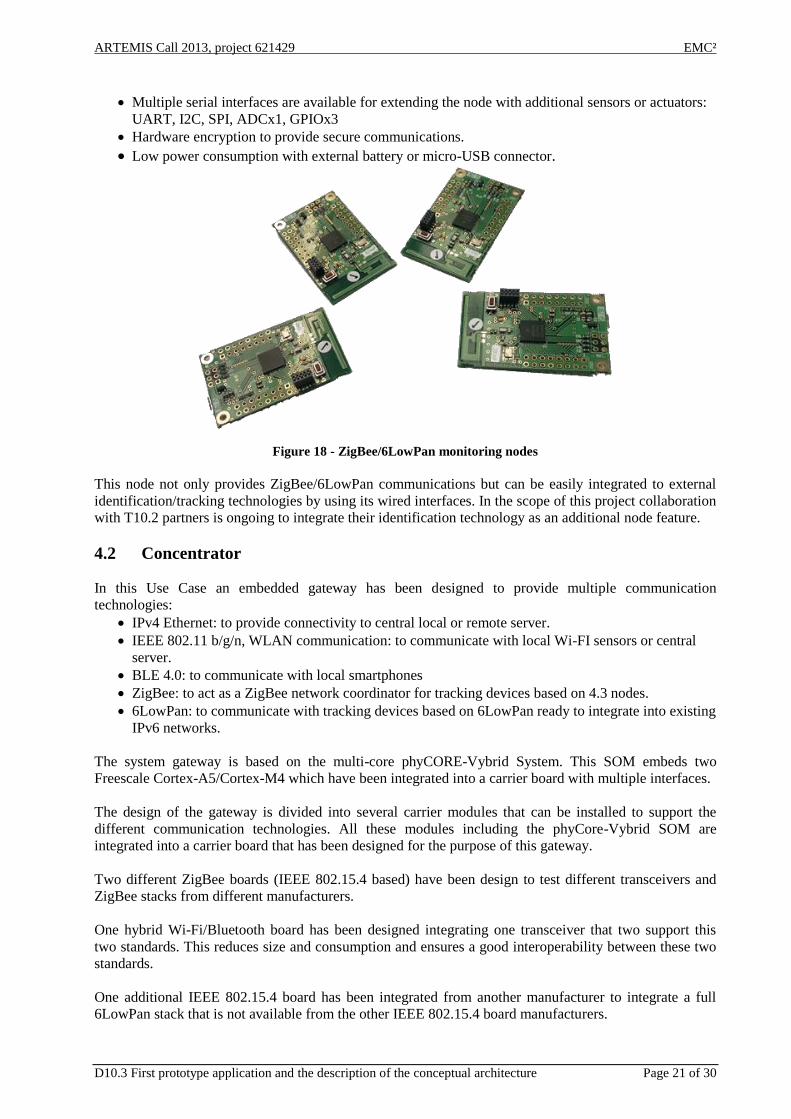
Multiple serial interfaces are available for extending the node with additional sensors or actuators:
UART, I2C, SPI, ADCx1, GPIOx3
Hardware encryption to provide secure communications.
Low power consumption with external battery or micro-USB connector.
Figure 18 - ZigBee/6LowPan monitoring nodes
This node not only provides ZigBee/6LowPan communications but can be easily integrated to external
identification/tracking technologies by using its wired interfaces. In the scope of this project collaboration
with T10.2 partners is ongoing to integrate their identification technology as an additional node feature.
4.2 Concentrator
In this Use Case an embedded gateway has been designed to provide multiple communication
technologies:
IPv4 Ethernet: to provide connectivity to central local or remote server.
IEEE 802.11 b/g/n, WLAN communication: to communicate with local Wi-FI sensors or central
server.
BLE 4.0: to communicate with local smartphones
ZigBee: to act as a ZigBee network coordinator for tracking devices based on 4.3 nodes.
6LowPan: to communicate with tracking devices based on 6LowPan ready to integrate into existing
IPv6 networks.
The system gateway is based on the multi-core phyCORE-Vybrid System. This SOM embeds two
Freescale Cortex-A5/Cortex-M4 which have been integrated into a carrier board with multiple interfaces.
The design of the gateway is divided into several carrier modules that can be installed to support the
different communication technologies. All these modules including the phyCore-Vybrid SOM are
integrated into a carrier board that has been designed for the purpose of this gateway.
Two different ZigBee boards (IEEE 802.15.4 based) have been design to test different transceivers and
ZigBee stacks from different manufacturers.
One hybrid Wi-Fi/Bluetooth board has been designed integrating one transceiver that two support this
two standards. This reduces size and consumption and ensures a good interoperability between these two
standards.
One additional IEEE 802.15.4 board has been integrated from another manufacturer to integrate a full
6LowPan stack that is not available from the other IEEE 802.15.4 board manufacturers.
ARTEMIS Call 2013, project 621429 EMC²
D10.3 First prototype application and the description of the conceptual architecture Page 22 of 30
The integration of different transceivers (based on IEEE 802.15.4) adds flexibility to gateway and ensures
that can support the communication with different custom implementations of ZigBee/6LowPan variants,
e.g. ZigBee Pro.
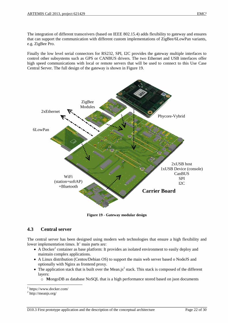
Finally the low level serial connectors for RS232, SPI, I2C provides the gateway multiple interfaces to
control other subsystems such as GPS or CANBUS drivers. The two Ethernet and USB interfaces offer
high speed communications with local or remote servers that will be used to connect to this Use Case
Central Server. The full design of the gateway is shown in Figure 19.
Figure 19 - Gateway modular design
4.3 Central server
The central server has been designed using modern web technologies that ensure a high flexibility and
lower implementation times. It’ main parts are:
A Docker1 container as base platform: It provides an isolated environment to easily deploy and
maintain complex applications.
A Linux distribution (Centos/Debian OS) to support the main web server based o NodeJS and
optionally with Nginx as frontend proxy.
The application stack that is built over the Mean.js2 stack. This stack is composed of the different
layers:
o MongoDB as database NoSQL that is a high performance stored based on json documents
1 https://www.docker.com/
2 http://meanjs.org/
2xUSB host
1xUSB Device (console)
CanBUS
SPI
I2C
Carrier Board
6LowPan
WiFi
(station+softAP)
+Bluetooth
ZigBee
Modules 2xEthernet
Phycore-Vybrid
ARTEMIS Call 2013, project 621429 EMC²
D10.3 First prototype application and the description of the conceptual architecture Page 23 of 30
o Express as framework for routing and
o Nodejs as the base platform that process the http queries and supports the other layers.
o Angularjs as the main user fronted to implement a responsive application.
4.4 Overview of contributions from technical WP’s
This section summarized the related contribution from the technical work packages. WP3 provides the
communication stacks to ensure a proper interoperability of the different communication interfaces
integrated into the gateway carrier board.
WP5 supports the development of the nodes and the gateway with custom console and IDE tools that are
being tuned to debug and monitor the gateway cores and nodes microcontroller.
4.5 Requirements
The requirement 15R_AMBAR_014 related to heterogeneous communications is covered by integrating
the multiple communication submodules into the gateway and allowing its extension via serial interfaces
if needed. This will make possible to use for different environments, transceivers, standards the optimal
communication technology for each application.
The requirement 15R_AMBAR_015 related to support heterogeneous indoor/outdoor location is
supported by different indoor wireless communication technologies (Wi-Fi, ZigBee, Bluetooth) that can
be used to build triangulation location support and range location. Outdoor location can be implemented
embedding an external GPS into the gateway to add a global reference point to the indoor system.
The requirement 15R_AMBAR_016 related to data tracking information management will be cover by
the central server implementing a local database and user interface to easily deploy and monitor the
tracked devices. This server also will support different web endpoints to allow integration with other
distributed applications, such as a smartphone Android application used for NFC/Bluetooth scanning.
5. T10.4 – UC_Manufacturing Quality Control by 3D Inspection
This section provides a description of the prototype under development at Task 10.4 “Manufacturing
Quality Control by 3D Inspection”. Then, a description of the followed conceptual architecture
approach it is described and linked to the requirements stated in D10.1. Finally, it is given a list of
properties of the prototype that have been used to evaluate the design and to provide feedback to the
applied technologies from WP2.
5.1 Description of the prototype
Quality control is a main concern in manufacturing processes. This UC propose the use of a 3D
inspection system to control the full output of a given production line. Each part has to be inspected to
ensure no errors are present in the produced parts. In order to provide an inspection system that avoids
common problems found at using mechanical handling, e.g. hiding surfaces or mechanical adaptation to
each manufactured part, a 3D inspection system based on machine vision while the parts are in free fall is
proposed. The 3D inspection system is based on a multi-camera configuration along a sphere-like
structure that allows the computing system to observe the part under study from every possible angle
without any occlusion. Using this set of images, the inspection system reconstructs the 3D shape of the
object as well as its corresponding texture. This information is used to compare the reconstructed object
with a reference system and to detect any important deviation from the manufacturing parameters.

ARTEMIS Call 2013, project 621429 EMC²
D10.3 First prototype application and the description of the conceptual architecture Page 24 of 30
This real-time inspection system requires the timeliness of the image capture process to be very precise
while providing a short enough response time to cope with the production line throughput requirements.
Starting with a functional version of the object reconstruction system, the aim of this UC is to take
advantage of the multicore platforms and the tools provided within the EMC2 project to obtain a highly
parallel and scalable version of inspection system.
Therefore, a very relevant features in this UC concerning with the EMC2 project are the latency and
scalability properties of the prototype, i.e. the object processing performed by the inspection system.
Specifically, a performance improvement of the object reconstruction stage can be achieved by
multiplying computing cores and implementing a software parallelization of most consuming functions.
In this way, latency is reduced by means of intra-node parallel computation (“Algorithm
parallelization”), whereas throughput is raised by means on inter-node distributed computation (“System
scalability”). Thus, it is important to remark the difference between the two types of parallelism that can
be applied to the prototype:
Internal (intra-node): Parallel processing of each image.
External (internode): Processing images in parallel.
Source code rewriting for algorithm intra-node parallelization has been carried out for the first
prototype application developed in this UC. Then, a comparison between a sequential and a parallel
model of the work performed at the inspection system to build a 3D representation of any digitized object
has been carried out. Both ways to reconstruct the 3D object have been modeled with the “art2kitekt” tool
imported from WP2. Although parallelization of flows is still under development for the tool, a
simulation has been achieved by the use of precedence order and artificial synchronization tasks. The next
step will be the use of several processors with a manual or automatic mapping of flows to processors.
Execution times of each task for sequential and parallel (external cores, no nested) models have been
measured and provided to the tool. Then, a feasibility report computed with the Response Time Analysis
algorithm has been returned by the tool.
In summary, a tool suite named “art2kitekt” developed in WP2 as an integrated software tool for
designing and analyzing mixed criticality, real-time systems has been applied to perform the modeling
and off-line analysis for a given execution platform and task set, with high performance demand.
Furthermore, an engineering process of design and analysis guided by the tool has been performed. A set
of parallel processes aimed to reconstruct a 3D object have been optimized to perform as fast as possible
on a virtual multi-core execution platform.
5.1.1 Detailed design of the first prototype
A first prototype has been developed as a proof of concept of how is possible to enable parallelism for a
function of the 3D reconstruction software. In the following examples it is illustrated how OpenMP is
applied to some functions of the software, where the background/foreground segmentation task is carried
out. In the future, the parallelization of the other tasks will respect this schema.
Next, a list of OpenMP directives used in the partial parallelization of the 3D reconstruction prototype is
provided:
Disable dynamic threading. It means to force the number of threads within a team to be
constant. A use example is:
#ifdef _OPENMP
omp_set_dynamic(0);
#endif

ARTEMIS Call 2013, project 621429 EMC²
D10.3 First prototype application and the description of the conceptual architecture Page 25 of 30
Nested parallelism. It can be enable or disabled at any point by explicit calls to OpenMP. When
enabled, all possible parallelism will be achieved at nested loops in the source code. Next a use
example is shown:
#ifdef _OPENMP
omp_set_nested(1); // enable
for (i=0; i<n; i++) {
for (j=0; j<m; j++ {
compute(a);
}
}
#endif
Active threads. By setting the number of active threads OpenMP will create a set of execution
threads that can be directly assigned to the available cores of the execution platform. Example:
#ifdef _OPENMP
omp_set_num_threads(n);
#endif
Finally, an example of the combined use of the previous directives in the first prototype is listed:
Silhouette segmentation. Source code example:
void segment_silhouette(i3d_reconstruc_data_t* rd) {
// set number of active threads for external loop done on images
set_num_threads(num_threads_ext);
// this instruction use OMP framework and each loop are done using several threads
#pragma omp parallel for
for (int ic = 0; ic < rd->num_cameras; ic++) {
// reserve memory for silhouette image
rd->silhouette_images[ic] =
cvCreateImage(cvSize(rd->cameras[ic].calibration_info.width,
rd->cameras[ic].calibration_info.height), IPL_DEPTH_8U, 1);
// set number of active threads for internal segmentation computing
// if nested parallelism is active, segmentation of one single image is done in parallel
// if not, next instruction has no effect and segmentation is performed by 1 thread
set_num_threads(num_threads_int);
// compute silhouette
get_silhouette_segmentation(rd->target_images[ic],
rd->background_images[ic],
&rd->config->segmentation_settings,
rd->silhouette_images[ic]);
}
}
5.2 Description of the conceptual architecture
A set of the specific requirements defined at D10.1 have guided the development in this task. Although
the complete list of requirements is available in [REQ-T10_4] (from D10.2), next it will be described
those that have already been taken into account for the conceptual architecture applied to the
prototype.
ARTEMIS Call 2013, project 621429 EMC²
D10.3 First prototype application and the description of the conceptual architecture Page 26 of 30
Requirement 15Q-WP10-REQ005 defines response time constraints that the system engineer should
meet without excessively incrementing other costs. Intensive work on algorithm parallelization for the 3D
object reconstruction has been carried out in order to achieve a version of the software able to take
advantage from a multicore execution platform. Original sequential code was unable to run on several
cores, thus preventing an optimal utilization of the proposed EMC2 execution platforms.
This milestone has been achieved by speeding up some stages of the 3D reconstruction algorithm through
the possibility to execute in parallel its corresponding code. Different features from OpenMP library have
been extensively applied to the algorithm, like pragma directives for loops, thread pools and message
queues which enabled us to improve performance by exploiting coarse parallelism on the inspection
system prototype.
This parallelization effort of the 3D reconstruction process using OpenMP has resulted in a parallel
version which has been compared against the sequential one. Both versions have been modeled with the
“art2kitekt” tool imported from WP2. This model has also allow us to analyze the performance critical 3D
reconstruction process for a given execution platform.
As a result, it has been obtained a response time improvement by OpenMP parallelization, around half
time reduction with parallelism. This is a good result but smaller than expected mainly due to lack of
CPU and cache affinity control provided by this approach. Furthermore, OpenMP framework does not
provide a fine control of thread-to-core assignment. Then, an engineering process of design and analysis
guided by the tool “art2kitekt” has been performed, resulting in a model of the parallel process aimed to
reconstruct a 3D object. This model will allow us to optimize and fine-tune the parallelization model to
take into account CPU hierarchies present in the selected execution platform.
5.3 Properties of the prototype
Next, some properties of the prototype developed under “Task 10.4 Manufacturing Quality Control by 3D
Inspection” are described. These properties have been used to evaluate the design and to provide
feedback to the applied technologies from WP2 and WP6.
From WP2 a tool named “Pareon” to find bugs (invalid memory accesses, uninitialized memory reads,
use of freed memory, race conditions, deadlocks, memory leaks) and optimize code has been used to
scan the core code of our 3D reconstruction process. This has helped us to be more confident on the
quality of our code, both on bug-free and parallel optimization concerns.
A compute vision testing tool from WP6 named Vitro has been used to generate a dataset (composed of
springs, angles, screws and tubes) that will be used as ground-truth. Our system configuration for the 3D
reconstruction process was modeled in order to set Vitro parameters to fit the physical positions of the
cameras. Then, 3D models were reconstructed and compared to the original ones. Analysis of the results
confirmed that the 3D reconstruction process is robust enough to pose-change but also showed complex
geometries that did not performed as good as expected. After having done all the analysis, the two teams
(ITI and AIT) met to discuss technical topics and possible improvements. Currently, an independent
dataset is available to check the performance of the reconstruction process.
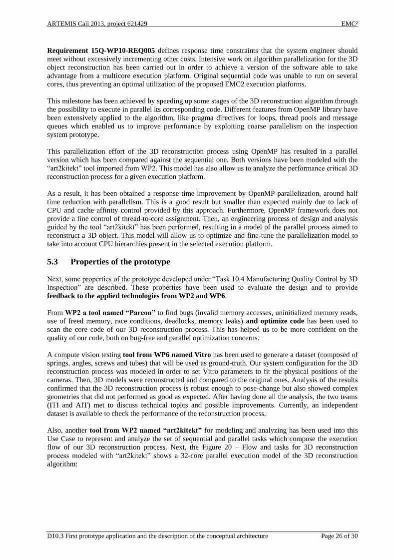
Also, another tool from WP2 named “art2kitekt” for modeling and analyzing has been used into this
Use Case to represent and analyze the set of sequential and parallel tasks which compose the execution
flow of our 3D reconstruction process. Next, the Figure 20 – Flow and tasks for 3D reconstruction
process modeled with “art2kitekt” shows a 32-core parallel execution model of the 3D reconstruction
algorithm:
ARTEMIS Call 2013, project 621429 EMC²
D10.3 First prototype application and the description of the conceptual architecture Page 27 of 30
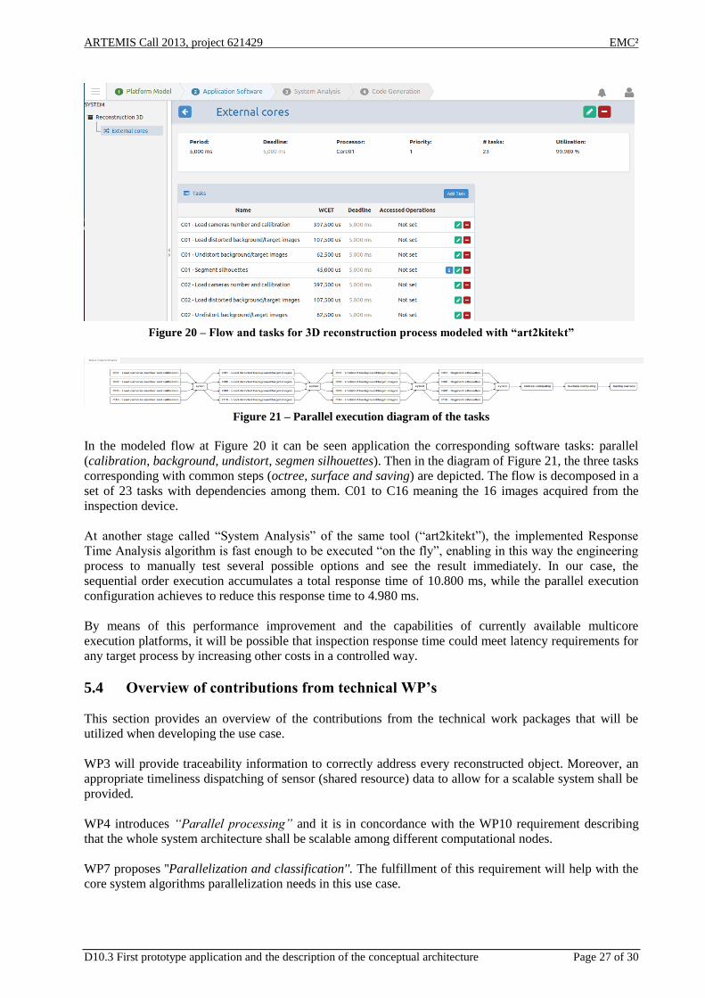
Figure 20 – Flow and tasks for 3D reconstruction process modeled with “art2kitekt”
Figure 21 – Parallel execution diagram of the tasks
In the modeled flow at Figure 20 it can be seen application the corresponding software tasks: parallel
(calibration, background, undistort, segmen silhouettes). Then in the diagram of Figure 21, the three tasks
corresponding with common steps (octree, surface and saving) are depicted. The flow is decomposed in a
set of 23 tasks with dependencies among them. C01 to C16 meaning the 16 images acquired from the
inspection device.
At another stage called “System Analysis” of the same tool (“art2kitekt”), the implemented Response
Time Analysis algorithm is fast enough to be executed “on the fly”, enabling in this way the engineering
process to manually test several possible options and see the result immediately. In our case, the
sequential order execution accumulates a total response time of 10.800 ms, while the parallel execution
configuration achieves to reduce this response time to 4.980 ms.
By means of this performance improvement and the capabilities of currently available multicore
execution platforms, it will be possible that inspection response time could meet latency requirements for
any target process by increasing other costs in a controlled way.
5.4 Overview of contributions from technical WP’s
This section provides an overview of the contributions from the technical work packages that will be
utilized when developing the use case.
WP3 will provide traceability information to correctly address every reconstructed object. Moreover, an
appropriate timeliness dispatching of sensor (shared resource) data to allow for a scalable system shall be
provided.
WP4 introduces “Parallel processing” and it is in concordance with the WP10 requirement describing
that the whole system architecture shall be scalable among different computational nodes.
WP7 proposes ''Parallelization and classification''. The fulfillment of this requirement will help with the
core system algorithms parallelization needs in this use case.

ARTEMIS Call 2013, project 621429 EMC²
D10.3 First prototype application and the description of the conceptual architecture Page 28 of 30
5.5 Requirements
This section provides a description of a set of the specific requirements that will guide the development in
Task 10.4 Manufacturing Quality Control by 3D Inspection. The complete set of requirements is available
in [REQ-T10_4].
The requirements 15Q-WP10-REQ005 “Algorithm parallelization” and 15Q-WP10-REQ006 “System
scalability” specify that performance improvement is a key point for this use case. Algorithm
parallelization and system scalability shall be addressed to achieve the main goal of this industrial
contribution: performance increase.
Moreover, both requirements will enable the system to adjust costs while matching system constraints.
On the one hand, the main algorithms of the inspection system prototype shall be parallelized in order to
reduce process latency in a multi-core execution platform. This is the reason for requirement 15Q-WP10-
REQ005 “Algorithm parallelization” to state that the core system algorithms shall be parallelized.
At the other hand, a new dispatching stage shall allow the system to balance workload among different
processing nodes to reach the required throughput. By this stage, represented with 15Q-WP10-REQ006
“System scalability” requirement, the whole system architecture shall be scalable among different
computational nodes.
Finally, the requirement 15Q-WP10-REQ007 describes a critical aspect of the 3D inspection system, i.e.
the proper and precise synchronization between the capture process and the data delivery process, which
is responsible for distributing the images among computing nodes devoted to the 3D reconstruction. An
accurate dispatching of sensor data will allow the system to reach a maximum performance, only bounded
by the throughput of the 3D image capture device.
6. Conclusions
The preceding sections have described the four uses cases within the industrial domain. The four use
cases represent four different industrial applications: (1) Variable Speed Drives in Industrial Applications,
(2) Identification and Authentication, (3) Tracking and (4) Manufacturing Quality Control by 3D
Inspection. For each use case we have developed a conceptual architecture and corresponding prototype
addressing the requirements listed in deliverable [D10.1]. None of the prototypes completely fulfill all the
set requirements but we have made significant progress. Development has been based both on the
technologies developed in the technology work packages and on experience that WP10 partners have in
their corresponding industrial domains.
(1) A Variable Speed Drive conceptual architecture and the prototype demonstrate the separation of time
critical computations from rest of the computations. It also shows an approach to reach some of the safety
requirements. Architecture also demonstrates the use of declarative components and flexible deployment.
It also had model based motor control. In summary, we demonstrate that multicore SoC can be used as a
platform to control variable speed drives.
(2) Identification and authentication of participants in secure communication processes to either allow or
deny access to the system. The objective of this use case is to develop and implement a flexible multi-
core root of trust. This multi secure element core handler provides confidentiality, message
authentication, message integrity and non-repudiation/denial of sending messages. The prototype
demonstrates the functionality of multi-secure element handler. It can handle single sided authentication,
mutual authentication and session key establishment.

ARTEMIS Call 2013, project 621429 EMC²
D10.3 First prototype application and the description of the conceptual architecture Page 29 of 30
(3) A heterogeneous tracking system integrates multiples identification and communication wireless
technologies to build an efficient solution with reasonable costs of deployment and maintenance. This
architecture supports multiple tracking devices, concentrator and central server. Tracking devices can user
passive RFID tags for basing identification, Bluetooth beacons for extra location functionalities and
ZigBee/6LowPan nodes for continuous monitoring. The concentrator supports multiple communication
technologies (IPv4 Ethernet, IEEE 802.11 b/g/n, BLE 4.0, ZigBee and 6LowPan). Central server is based
on top of Linux using NodeJS as web server, application stack over Mean.js stack and Docker container
as base platform. Together these technologies support indoor tracking.
(4) Manufacturing Quality Control by 3D Inspection resolves some problems that arise at the industrial
inspection field, avoiding the associated problems with mechanical handling. The performance of this
process may be improved by adding computing cores. At the same time, a precise synchronization
between the acquisition process and the computing nodes need to be preserved, thus imposing hard real-
time constraints that will be meet by the work to be carried out in the context of the project. The first
prototype demonstrates how OpenMP directives can be used to parallelize background/foreground
segmentation tasks. Tests show that time reduction due to parallel processing reducing the task time to
half.
These conceptual architectures and the prototypes will be carefully analyzed. The analysis results will be
used in improving the conceptual architecture addressing each use case and in developing later
prototypes. Feedback will be given to technology work packages so that technology in the future can even
better support these use cases.

ARTEMIS Call 2013, project 621429 EMC²
D10.3 First prototype application and the description of the conceptual architecture Page 30 of 30
7. References
[IEC 61800-5-1] IEC 61800-5-1, Adjustable speed electrical power drive systems – Part 5-1: Safety
requirements – Electrical, thermal and energy, 2nd
edition 2007-07, International
Electrotechnical Commission (IEC), 2007.
[IEC 61800-5-2] IEC 61800-5-2, Adjustable speed electrical power drive systems – Part 5-2: Safety
requirements –Functional, 1st edition 2007-07, International Electrotechnical
Commission (IEC), 2007.
[D10.1] D10.1 Requirements for Industrial Applications, edited by Jesper Berthing, EMC2
Project Consortium, 2014
[D10.2] D10.2 Evaluation of the requirements against the current solutions and the gap analysis,
edited by Christopher Nigischer, EMC2 Project Consortium, 2015
[REQ-T10_1] EMC2_REQ_WP10_Task_10_1.xlsx
[REQ-T10_2] EMC2_REQ_WP10_Task_10_2.xlsx
[REQ-T10_3] EMC2_REQ_WP10_Task_10_3.xlsx
[REQ-T10_4] EMC2_REQ_WP10_Task_10_4.xlsx
[UL 508C] Power Conversion Equipment, Underwriters Laboratories
[UL 61800-5-1] Adjustable Speed Electrical Power Drive Systems - Part 5-1: Safety Requirements -
Electrical, Thermal and Energy, Underwriters Laboratories