embedded real-time systems 18-349: introduction to ...mmio.pdf · (postfix instruction with a ......
TRANSCRIPT

EmbeddedReal-TimeSystems
18-349: Introduction to Embedded Real-Time Systems
Lecture 4: ARM ASM Part 2Anthony RoweElectrical and Computer EngineeringCarnegie Mellon University

EmbeddedReal-TimeSystems
Kaboom Explained…
2
PowerSwitch…MIC94091vsMIC94092

EmbeddedReal-TimeSystems
Last Lecture§ Exceptions
§ Vector Table
§ Pipelining§ What is it?§ Why do we do it?
§ ARM ISA Introduction§ Move operations§ Arithmetic operations§ Logical operations§ Comparison operations§ Multiply operations§ Conditionals
3
EmbeddedReal-TimeSystems
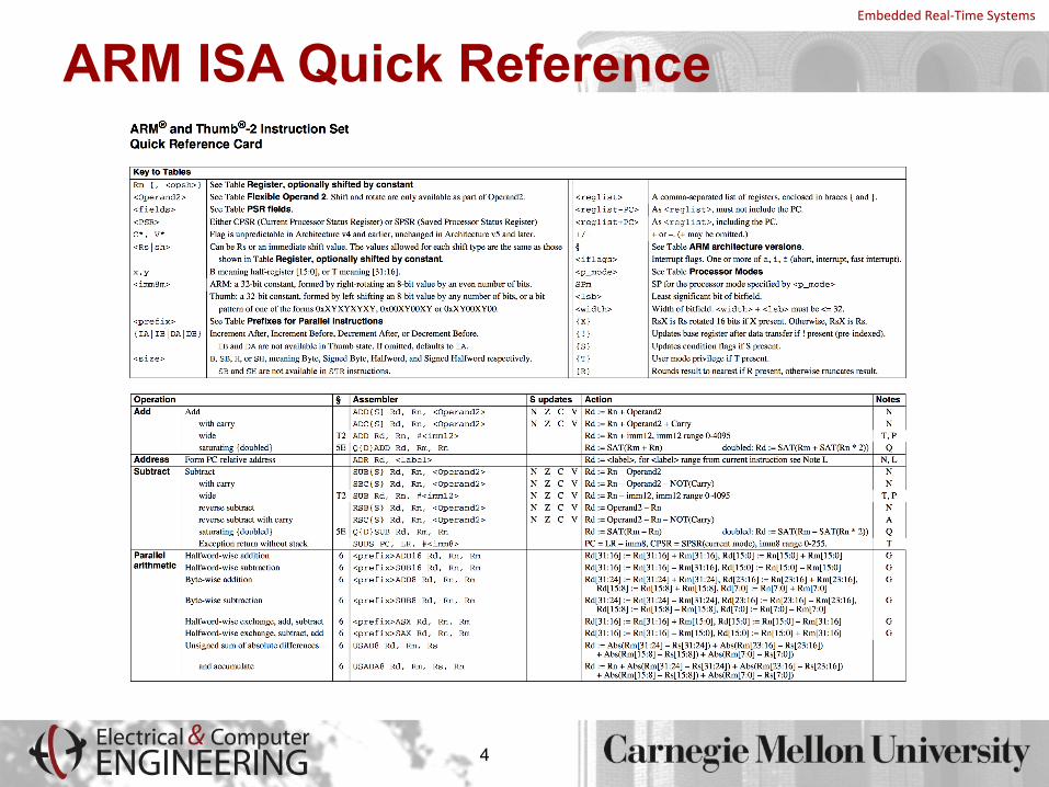
ARM ISA Quick Reference
4

EmbeddedReal-TimeSystems
Branch Instructions§ To change the flow of execution or to call a routine
§ Supports subroutine calls, if-then-else structures, loops
§ Change of execution forces the pc to point to a new address
§ Different branch instructions on the ARM§ B{<cond>} label
§ BL{<cond>} label
§ BX{<cond>} Rm
5

EmbeddedReal-TimeSystems
Lecture Overview§ ARM ASM Part 2
§ Addressing Modes (review)§ Batch load§ Stack
§ Memory Mapped Input Output (MMIO)
6

EmbeddedReal-TimeSystems
LDR and STR§ LDR and STR instructions can load and store data on a boundary alignment
that is the same as the datatype size being loaded or stored
§ LDR can only load 32-bit words on a memory address that is a multiple of 4 bytes – 0, 4, 8, and so on
§ LDR r0, [r1]
§ Loads register r0 with the contents of the memory address pointed to by register r1
§ STR r0, [r1]
§ Stores the contents of register r0 to the memory address pointed to by register r1
§ Register r1 is called the base address register
7

EmbeddedReal-TimeSystems
LDR/STR Example
8
§ The memory location to be accessed is held in a base register
STR r0, [r1] ; Store contents of r0 to location pointed; to by contents of r1.
LDR r2, [r1] ; Load r2 with contents of memory location; pointed to by contents of r1

EmbeddedReal-TimeSystems
Addressing Modes (1-4)§ ARM provides three addressing modes
§ Preindex with writeback§ Preindex§ Postindex
§ Preindex mode useful for accessing a single element in a data structure
§ Postindex and preindex with writeback useful for traversing an array
9

EmbeddedReal-TimeSystems
Addressing Modes (2-4)§ Preindex
§ Same as preindex with writeback, but does not update the base register§ Example: LDR r0, [r1, #4]
§ Preindex with writeback§ Calculates address from a base register plus address offset§ Updates the address in the base register with the new address§ The updated base register value is the address used to access memory§ Example: LDR r0, [r1, #4]!
§ Postindex§ Only updates the base register after the address is used§ Example: LDR r0, [r1], #4
10

EmbeddedReal-TimeSystems
Addressing Modes (3-4)
11
Preindexing withwriteback
LDR r0, [r1, #4]!
POST r0 =r1 =
PRE r0 = 0x00000000r1 = 0x00009000mem32[0x00009000] = 0x01010101mem32[0x00009004] = 0x02020202
Preindexing
LDR r0, [r1, #4]
POSTr0 = r1 =
Postindexing
LDR r0, [r1], #4
POST r0 = r1 =
0x020202020x00009004
0x020202020x00009000
0x010101010x00009004

EmbeddedReal-TimeSystems
Addressing Modes (4-4)
12
§ Address <address> accessed by LDR/STR is specified by § A base register plus an offset
§ Offset takes one of the three formats1. Immediate: offset is a number that can be added to or subtracted from the
base registerExample: LDR r0,[r1, #8]; r0 b mem[r1+8]
LDR r0,[r1, #-8]; r0 b mem[r1-8]
2. Register: offset is a general-purpose register that can be added to or subtracted from the base registerExample: LDR r0,[r1, r2]; r0 b mem[r1+r2]
LDR r0,[r1, -r2]; r0 b mem[r1-r2]
3. Scaled Register: offset is a general-purpose register shifted by an immediate value and then added to or subtracted from the base register
Example: LDR r0,[r1,r2, LSL #2]; r0 b mem[r1+4*r2]
EmbeddedReal-TimeSystems
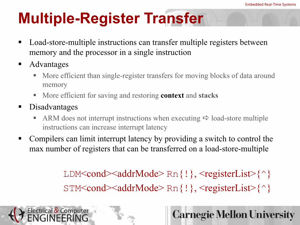
Multiple-Register Transfer§ Load-store-multiple instructions can transfer multiple registers between
memory and the processor in a single instruction§ Advantages
§ More efficient than single-register transfers for moving blocks of data around memory
§ More efficient for saving and restoring context and stacks§ Disadvantages
§ ARM does not interrupt instructions when executing a load-store multiple instructions can increase interrupt latency
§ Compilers can limit interrupt latency by providing a switch to control the max number of registers that can be transferred on a load-store-multiple
LDM<cond><addrMode> Rn{!}, <registerList>{^}STM<cond><addrMode> Rn{!}, <registerList>{^}

EmbeddedReal-TimeSystems
More on Load-Store-Multiple§ Transfer occurs from a base-address register Rn pointing into memory§ Transferred registers can be either
§ Any subset of the current bank of registers (default)§ Any subset of the user mode bank of registers when in a privileged mode
(postfix instruction with a ‘^’)§ Processor not in user mode or system mode§ Writeback is not possible, i.e., ! cannot be supported at the same time§ If pc is in the list of registers, additionally copy spsr to cpsr
§ Register Rn can be optionally updated following the transfer§ If register Rn is followed by the ! character
§ Registers can be individually listed or lumped together as a range§ Use a comma with “{“ and “}” parentheses to list individual registers§ Use a “-” to indicate a range of registers§ Good practice to list the registers in the order of increasing register number
(since this is the usual order of memory transfer)

EmbeddedReal-TimeSystemsAddressing Modes for Load-Store-Multiple§ Suppose that N is the number of registers in the list of registers
§ xxxIA (increment after)§ Start reading at address Rn; ending address is Rn + 4N – 4§ Rn! equals Rn + 4N
§ xxxIB (increment before)§ Start reading at address Rn+4; ending address is Rn + 4N§ Rn! equals Rn + 4N
§ xxxDA (decrement after)§ Start reading at address Rn – 4N + 4; ending address is Rn§ Rn! equals Rn - 4N
§ xxxDB (decrement before)§ Start reading at address Rn – 4N; ending address is Rn - 4§ Rn! equals Rn - 4N
§ ARM convention: DB and DA are like loading the register list backwards from sequentially descending memory addresses

EmbeddedReal-TimeSystems
Things to Remember§ Any register can be used as the base register§ Any register can be in the register list§ Order of registers in the list does not matter§ The lowest register always uses the lowest memory address regardless of
the order in which registers are listed in the instruction§ LDM and STM instructions only transfer words
§ Unlike LDR/STR instructions, they don’t transfer bytes or half-words§ Can specify range instead of individual registers
§ Example: LDMIA r10!, {r12, r2-r7} § If the base register is updated (using !) in the instruction, then it cannot be
a part of the register set§ Example: LDMIA r10!, {r0, r1, r4, r10} is not allowed

EmbeddedReal-TimeSystems
ExamplesPREr0 = 0x00080010
r1 = 0x00000000r2 = 0x00000000 r3 = 0x00000000mem32[0x8001c] = 0x04mem32[0x80018] = 0x03mem32[0x80014] = 0x02mem32[0x80010] = 0x01
0x00080020 0x05
0x0008001c 0x04
0x00080018 0x03
0x00080014 0x02
0x00080010 0x01
0x0008000c 0x00
r0(original)
LDMIA r0!, {r1-r3}
POSTr0 = r1 = r2 = r3 =
LDMIB r0!, {r1-r3}
POSTr0 = r1 = r2 = r3 =
0x0008001c0x010x020x03
0x0008001c0x020x030x04

EmbeddedReal-TimeSystems
Example 1: Saving & Restoring Registers§ Here’s what we want to accomplish
§ Save the contents of registers r1, r2 and r3 to memory§ Mess with the contents of registers r1, r2 and r3§ Restore the original contents of r1, r2 and r3 from memory & restore r0
PREr0 = 0x00009000r1 = 0x09r2 = 0x08 r3 = 0x07
;storecontentstomemorySTMIB r0!, {r1-r3};messwithregistersr1,r2,r3MOV r1, #1MOV r2, #2MOV r3, #3;restoreoriginalr1,r2,r3LDMDA r0!, {r1-r3}
0x0000900c
0x00009008
0x00009004
0x00009000r0
(original)
ARM convention: Highest memory location maps to highest numbered register
0x070x080x09

EmbeddedReal-TimeSystems
Example 1: Block Copying§ Here’s what we want to accomplish
§ Copy blocks of 32 bytes from a source address to a destination address§ r9 points to the start of the source data§ r10 points to the start of the destination data§ r11 points to the end of the source data
loop;load32bytesfromsourceaddressandupdater9 pointerLDMIA r9!, {r0-r7};store32bytestodestinationaddressandupdater10 pointerSTMIA r10!, {r0-r7};checkifwearedonewiththeentireblockcopyCMP r9, r11;continueuntildoneBNE loop

EmbeddedReal-TimeSystems
Stack Operations§ ARM uses load-store-multiple instructions to accomplish stack operations§ Pop (removing data from a stack) uses load-multiple§ Push (placing data on a stack) uses store-multiple§ Stacks are ascending or descending
§ Ascending (A): Grow towards higher memory addresses§ Descending (D): Grow towards lower memory addresses
§ Stacks can be full or empty§ Full (F): Stack pointer sp points to the last used or full location § Empty (E): Stack pointer sp points to the first unused or empty location
§ Four possible variants§ Full ascending (FA) – LDMFA & STMFA§ Full descending (FD) – LDMFD & STMFD§ Empty ascending (EA) – LDMEA & STMEA§ Empty descending (ED) – LDMED & STMED

EmbeddedReal-TimeSystems
Stacks on the ARM§ ARM has an ARM-Thumb Procedure Call Standard
(ATPCS)§ Specifies how routines are called and how registers are
allocated§ Stacks according to ATPCS
§ Full descending§ What does this mean for you?
§ Use STMFD to store registers on stack at procedure entry§ Use LDMFD to restore registers from stack at procedure
exit § What do these handy aliases actually represent?
§ STMFD = STMDB (store-multiple-decrement-before)§ LDMFD = LDMIA (load-multiple-increment-after)

EmbeddedReal-TimeSystems
ExamplePREr1 = 0x00000002
r4 = 0x00000003sp = 0x00080014
STMFD sp!, {r1, r4}
0x00080018 0x05
0x00080014 0x04
0x00080010 Empty0x0008000c Empty
sp(original)
0x00080018 0x05
0x00080014 0x04
0x00080010 0x030x0008000c 0x02sp
(final)

EmbeddedReal-TimeSystems
SW Stack Checking§ Three stack attributes to be preserved (/swst assembler option)§ Stack base
§ Starting address of the stack in memory§ If sp goes past the stack base, stack underflow error occurs
§ Stack pointer (sp)§ Initially points to the stack base§ As data is inserted when a program executes, sp descends memory and points
to top of the stack§ Stack limit (sl)
§ If sp passes the stack limit, a stack overflow error occurs§ ATPCS: r10 is defined as sl
§ If sp is less than r10 after items are pushed on the stack, stack overflow occurs

EmbeddedReal-TimeSystems
Call Chain
24
R13– StackPointer(SP)R14– LinkRegister(LR)R15– ProgramCounter(PC)

EmbeddedReal-TimeSystems
Instruction Support for Functionsmain(){
... sum(a,b); // a,b:r4,r5...
}
int sum(int x, int y) {
return x + y;}
address1000 mov r0, r4 @ x = a1004 mov r1, r5 @ y = b 1008 bl sum @ lr = 1012 branch to sum1012 ...2000 sum: ADD r0, r0, r12004 BX lr @ MOV pc, lr i.e., return
Note: returns to address 1012
C
ARM

EmbeddedReal-TimeSystems
Register Saving Conventions§ When procedure yoo calls who:
§ yoo is the caller§ who is the callee
§ Can Register be used for temporary storage?§ Conventions (ATPCS is part of ABI)
§ Application Binary Interface (ABI)§ “CallerSave”
§ Caller saves temporary values in its frame before the call§ R0-R3
§ “Callee Save”§ Callee saves temporary values in its frame before using§ R4-R11 (sometimes R12)

EmbeddedReal-TimeSystems
Register Usage
r8r9/sbr10/slr11
r12
r13/spr14/lrr15/pc
r0r1r2r3
r4r5r6r7Register variables
Must be preserved
Arguments into functionResult(s) from functionotherwise corruptible(Additional parameters passed on stack)
Scratch register(corruptible)
Stack PointerLink Register
Program Counter
Register
- Stack base- Stack limit if software stack checking selected
- R14 can be used as a temporary once value stacked- SP should always be 8-byte (2 word) aligned

EmbeddedReal-TimeSystems
Course Hardware
28
RaspberryPi2BCM2836SoCBroadcom900MHzquad-coreARMCortex-A7Cores:4L1cache:32KBinstruction,32KBdata*L2cache:512KB*RAM:1GBRAM(offchip)SDHCslotforFlashBroadcomVideoCore IVReleasedFeb2015
*Estimatebasedonsleuthing…
ANDlotsofI/Odevices…

EmbeddedReal-TimeSystems
Rpi Boot Process§ 3 bootloaders§ First stage (on-chip ROM):
§ ARM in RESET mode§ Has code to load FAT32 file system on SD card and loads
bootcode.bin into memory to be used by GPU
§ Second stage (bootcode.bin):§ Enables on-chip RAM§ Loads start.elf from SD card into memory for GPU
§ Third stage (start.elf):§ Contains GPU firmware and splits up the 1 GB of RAM between GPU
and ARM CPUs (more about this in lab1)§ Then looks on SD card for kernel.img and loads it to 0x8000 and
sets *one* ARM CPU pc=0x8000§ kernel.img -> Enables JTAG hardware
29

EmbeddedReal-TimeSystemsInterfacing Peripheral Devices to the Processor§ So far we have looked at the ARM instruction set, programmer’s model§ Up next: How do we interface peripheral devices to the processor?§ We will look at
§ How do we set up (configure) peripheral devices?§ How do we check the status of the devices?§ How do we communicate with peripheral devices?

EmbeddedReal-TimeSystems
Software Addressing of I/O Devices § Two ways of addressing I/O devices from the CPU
§ Memorymapped I/O§ Devices are mapped in memory address space, e.g., the 7-segment LED§ Standard load and store instruction can manipulate devices
§ Port-mapped I/O§ Devices are not kept in memory address space § Special processor instructions request data from devices
§ Example IN REG, PORT
OUT REG, PORT
§ Which one is better? § Memorymapped I/O uses the same load/store paradigm, but costs some of the
address space § Full address space is available for port-mapped I/O, but requires extra
instructions and control signals from the CPU

EmbeddedReal-TimeSystems
Example§ Device manufacturer will typically specify the registers that will be used to
set up and control the device§ The hardware designers will specify the address of these devices on your
system§ You will write code to set up the devices, use the devices

EmbeddedReal-TimeSystems
Example§ Example: Suppose your hardware board has a 7-segment LED display § Assume that the device manufacturer specifies that there is a register that can be
written to display a character on the LED § The device manufacturer will also provide a table that determines the contents
of the register for each character to be displayed)§ The hardware designer will specify the address where this register is mapped
(assume that you are given that the device is mapped at 0x20200000§ If you wanted to display a character “P” on the LED, the code you will
write will look likeLDR R0,=0x20200000 MOV R1,#0x0C
STRB R1,[R0]
// LED character map#define LEDcharP 0x0c#define LEDcharH 0x09#define LEDcharA 0x08…
EmbeddedReal-TimeSystems
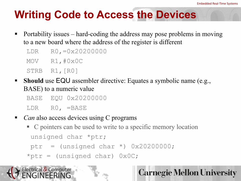
Writing Code to Access the Devices § Portability issues – hard-coding the address may pose problems in moving
to a new board where the address of the register is different LDR R0,=0x20200000
MOV R1,#0x0C
STRB R1,[R0]
§ Should use EQU assembler directive: Equates a symbolic name (e.g., BASE) to a numeric valueBASE EQU 0x20200000
LDR R0, =BASE
§ Can also access devices using C programs§ C pointers can be used to write to a specific memory location unsigned char *ptr;
ptr = (unsigned char *) 0x20200000;
*ptr = (unsigned char) 0x0C;

EmbeddedReal-TimeSystems
I/O Register Basics § I/O Registers are NOT like normal memory
§ Device events can change their values (e.g., status registers) § Reading a register can change its value (e.g., error condition reset)
§ For example, can't expect to get same value if read twice § Some are readonly (e.g., receive registers) § Some are writeonly (e.g., transmit registers) § Sometimes multiple I/O registers are mapped to same address
§ Selection of one based on other info (e.g., read vs. write or extra control bits)
§ Cache must be disabled for memorymapped addresses – why?§ When polling I/O registers, should tell compiler that value can change on
its own and therefore should not be stored in a register§ volatile int *ptr; (or int volatile *ptr;)
EmbeddedReal-TimeSystems
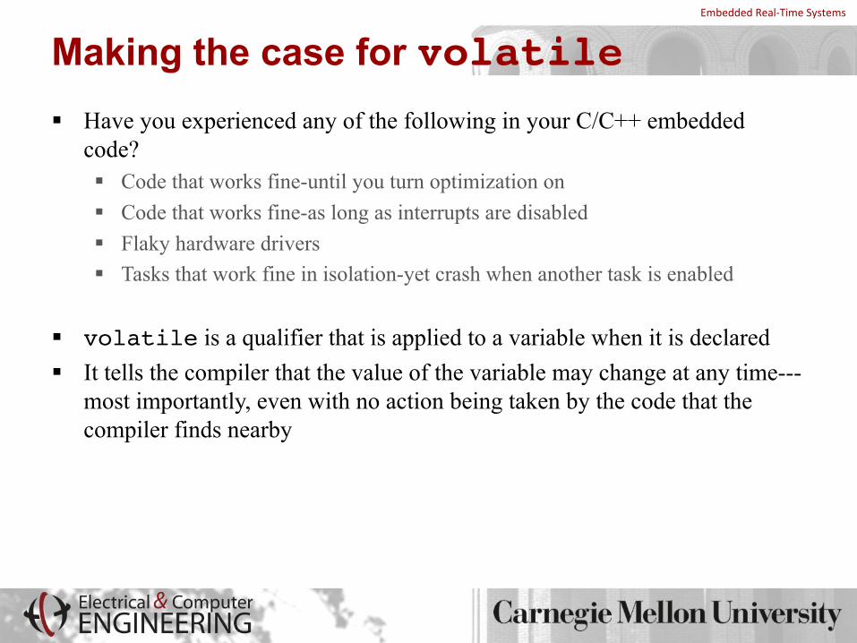
Making the case for volatile§ Have you experienced any of the following in your C/C++ embedded
code?§ Code that works fine-until you turn optimization on§ Code that works fine-as long as interrupts are disabled§ Flaky hardware drivers§ Tasks that work fine in isolation-yet crash when another task is enabled
§ volatile is a qualifier that is applied to a variable when it is declared§ It tells the compiler that the value of the variable may change at any time---
most importantly, even with no action being taken by the code that the compiler finds nearby
EmbeddedReal-TimeSystems
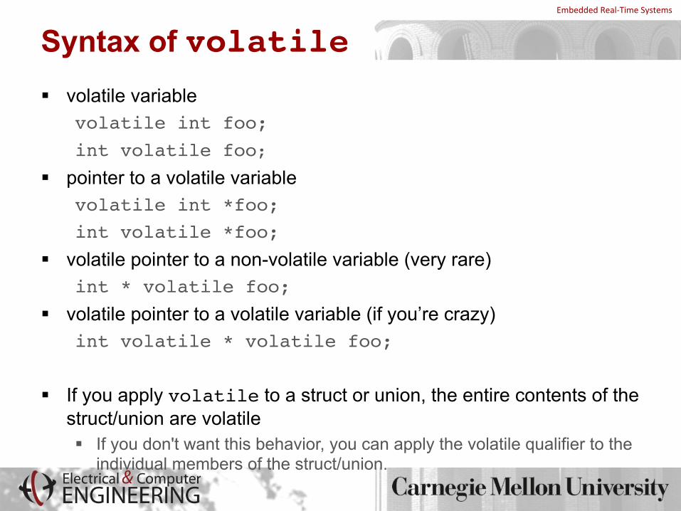
Syntax of volatile§ volatile variable
volatile int foo; int volatile foo;
§ pointer to a volatile variablevolatile int *foo; int volatile *foo;
§ volatile pointer to a non-volatile variable (very rare)int * volatile foo;
§ volatile pointer to a volatile variable (if you’re crazy)int volatile * volatile foo;
§ If you apply volatile to a struct or union, the entire contents of the struct/union are volatile§ If you don't want this behavior, you can apply the volatile qualifier to the
individual members of the struct/union.

EmbeddedReal-TimeSystems
The Use of volatile (1)§ A variable should be declared volatile if its value could change
unexpectedly§ Memory-mapped I/O registers§ Global variables that can be modified by an interrupt service
routine§ Global variables within multi-threaded applications
§ Example: Let’s poll an 8-bit I/O status register at 0x1234 until it is non-zero
unsigned int *ptr = (unsigned int *) 0x1234; // wait for I/O register to become non-zerowhile (*ptr == 0); // do something else
What’s wrong with this code? How would you fix it?
EmbeddedReal-TimeSystems
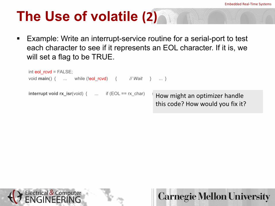
The Use of volatile (2)§ Example: Write an interrupt-service routine for a serial-port to test
each character to see if it represents an EOL character. If it is, we will set a flag to be TRUE.
int eol_rcvd = FALSE;void main(){ ... while (!eol_rcvd) { // Wait } ...}
interrupt void rx_isr(void){ ... if (EOL == rx_char) { eol_rcvd = TRUE; } ...}Howmightanoptimizerhandlethiscode?Howwouldyoufixit?

EmbeddedReal-TimeSystems
Thoughts on volatile§ What does the keyword volatile accomplish?
§ Tells the compiler not to perform certain optimizations§ Tells the compiler not to use the cached version of the variable§ Indicates that that variable can change asynchronously
§ Some compilers allow you to declare everything as volatile§ Don’t! It’s a substitute for good thinking§ Can lead to less efficient code
§ Don’t blame the optimizer and don’t turn it off
§ If you are given a piece of code whose behavior is unpredictable§ Look for declarations of volatile variables§ Look for where you should declare a variable as volatile