embedded systems hwembedded systems hw - …people.cs.aau.dk/~apr/itvhsi/seminar2/itev-es-hw.pdf ·...
TRANSCRIPT


A “short list” of embedded systems
Anti-lock brakesAuto-focus camerasA t ti t ll hi
ModemsMPEG decodersN t k dAutomatic teller machines
Automatic toll systemsAutomatic transmissionAvionic systemsBattery chargers
Network cardsNetwork switches/routersOn-board navigationPagersPhotocopiers
CamcordersCell phonesCell-phone base stationsCordless phonesCruise control
Point-of-sale systemsPortable video gamesPrintersSatellite phonesScanners
Curbside check-in systemsDigital camerasDisk drivesElectronic card readersElectronic instruments
Smart ovens/dishwashersSpeech recognizersStereo systemsTeleconferencing systemsTelevisions
Electronic toys/gamesFactory controlFax machinesFingerprint identifiersHome security systems
Temperature controllersTheft tracking systemsTV set-top boxesVCR’s, DVD playersVideo game consoles
And the list goes on and on
Life-support systemsMedical testing systems
Video phonesWashers and dryers

Processor technologyProcessor technology• Processors vary in their customization for the problem at hand
total = 0for i = 1 to N loop
total += M[i]total += M[i]end loopDesired
functionality
General-purpose
Single-purpose
Application-specific processor
processor processor

General-purpose processorsGeneral purpose processors• Programmable device used in a
variety of applications DatapathControllervariety of applications– Also known as “microprocessor”
• FeaturesRegister
file
p
Control logic and
State register– Program memory
– General datapath with large register file and general ALU
IR PCGeneral
ALU
register
• User benefits– Low time-to-market and NRE costs– High flexibility
Program memory
Assembly code for:
Datamemory
g y• “Pentium” the most well-known, but
there are hundreds of otherstotal = 0for i =1 to …

Single-purpose processorsSingle purpose processors• Digital circuit designed to execute DatapathController
exactly one program– a.k.a. coprocessor, accelerator or
peripheral
DatapathController
Control logic
State
index
totalp p
– JPEG codec
• FeaturesC t i l th t d d t
State register
Data
+
– Contains only the components needed to execute a single program
– No program memory
memory
• Benefits– Fast– Low powerLow power– Small size

Application-specific processors
• Programmable processor optimized for DatapathController
a particular class of applications having common characteristics– Compromise between general-purpose
Registers
Custom
Control logic and
State registerCompromise between general purpose
and single-purpose processors– EG microController, DSP
Features
IR PC ALU
Program
g
Datamemory• Features
– Program memory– Optimized datapath
Program memory
Assembly code for:
memory
– Special functional units
• BenefitsSome flexibility good performance size
total = 0for i =1 to …
– Some flexibility, good performance, size and power

IC technologyIC technology• The manner in which a digital (gate-level) g (g )
implementation is mapped onto an IC– IC: Integrated circuit, or “chip”– IC technologies differ in their customization to a design– IC’s consist of numerous layers (perhaps 10 or more)
IC technologies differ with respect to who builds each layer• IC technologies differ with respect to who builds each layer and when
source drainchanneloxidegate
Silicon
IC package IC
Silicon substrate

IC technologyIC technology• Three types of IC technologiesThree types of IC technologies
– Full-custom/VLSI– Semi-custom ASIC (gate array and standardSemi custom ASIC (gate array and standard
cell)– PLD (Programmable Logic Device)PLD (Programmable Logic Device)

Full-custom/VLSIFull custom/VLSI• All layers are optimized for an embedded system’s y p y
particular digital implementation– Placing transistors– Sizing transistors– Routing wires
B fi• Benefits– Excellent performance, small size, low power
D b k• Drawbacks– High NRE cost (e.g., $300k), long time-to-market
NRE=Non Recurring Engineering (design)– NRE=Non Recurring Engineering (design)

Semi-customSemi custom
• Lower layers are fully or partially builtLower layers are fully or partially built– Designers are left with routing of wires and
maybe placing some blocksmaybe placing some blocks• Benefits
Good performance good size less NRE cost– Good performance, good size, less NRE cost than a full-custom implementation (perhaps $10k to $100k)$10k to $100k)
• DrawbacksStill require weeks to months to develop– Still require weeks to months to develop

PLD (Programmable Logic D i )Device)
• All layers already existAll layers already exist– Designers can purchase an IC– Connections on the IC are either created or destroyed y
to implement desired functionality– Field-Programmable Gate Array (FPGA) very popular
• Benefits– Low NRE costs, almost instant IC availability
D b k• Drawbacks– Bigger, expensive (perhaps $30 per unit), power
hungry slowerhungry, slower

The co-design ladderThe co design ladder• In the past: Sequential program code (e.g., C, VHDL)
– Hardware and software design technologies were very different Assembly instructions
Register transfers
Compilers(1960's,1970's)
Behavioral synthesis(1990's)
RT synthesis– Recent maturation of
synthesis enables a unified view of hardware
y
Machine instructions
Assemblers, linkers(1950's, 1960's)
RT synthesis(1980's, 1990's)
Logic synthesis(1970's 1980's)
Logic equations / FSM's
and software
• Hardware/software “codesign” Implementation
Machine instructions (1970 s, 1980 s)
Microprocessor plus VLSI, ASIC, or PLD
Logic gates
codesignprogram bits: “software” implementation:
“hardware”The choice of hardware versus software for a particular function is simply a tradeoff among various design metrics, like performance, power, size, NRE cost, and especially flexibility; there is no fundamental difference between what hardware or software can
13
implement.
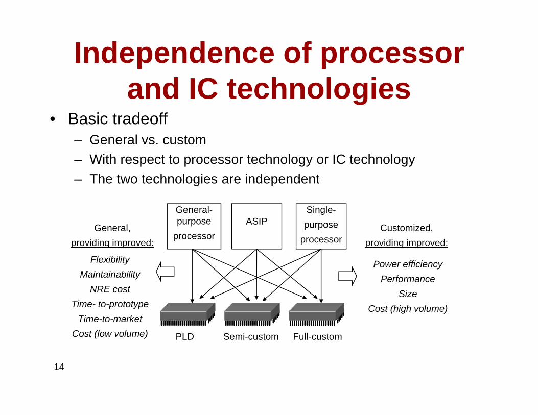
Independence of processor and IC technologies
• Basic tradeoff– General vs. custom– With respect to processor technology or IC technology– The two technologies are independentThe two technologies are independent
General-purpose ASIP
Single-purposeGeneral, Customized,
processor processorproviding improved: providing improved:
Power efficiencyPerformance
FlexibilityMaintainability
NRE t
Semi-customPLD Full-custom
SizeCost (high volume)
NRE costTime- to-prototype
Time-to-marketCost (low volume)
14
Semi customPLD Full custom( )

Design productivity gapDesign productivity gap• Moore’s Law• While designer productivity has grown at an impressive
rate over the past decades, the rate of improvement has not kept pace with chip capacitynot kept pace with chip capacity
10,0001,000
100Logic transistors
100,000
10,000
1000
10
1
0.1
0 01
Logic transistors per chip
(in millions)100
10
1
0 1
Productivity(K) Trans./Staff-Mo.
IC capacity
productivity
Gap
0.01
0.001
0.1
0.01

Design productivity gapDesign productivity gap• 1981 leading edge chip required 100 designer months
– 10,000 transistors / 100 transistors/month• 2002 leading edge chip requires 30,000 designer months
– 150,000,000 / 5000 transistors/month, ,• Designer cost increase from $1M to $300M
10,000
100,00001,000
100101
0 1
Logic transistors per chip
(in millions)
10,0001000100101
Productivity(K) Trans./Staff-Mo.
IC capacityGap
0.10.01
0.001
10.10.01
productivity

NXTNXT

NXT HW Block DiagramNXT HW Block Diagram• Atmel 32 bit ARM• 48 MHz• 256 KB Flash• 64 KB RAM
• 8 bit AVR (ATmega48)• 4KB FLASH4KB FLASH• 512 B RAM• 8 MHz

Output PortsOutput Ports

Pulse width modulatorPulse width modulator• Generates pulses with
specific high/low timesclk
pwm_o
25% duty cycle – average pwm_o is 1.25V
specific high/low times• Duty cycle: % time high
– Square wave: 50% duty cycle
clk
pwm_o
cycle• Common use: control
average voltage to electric device
50% duty cycle – average pwm_o is 2.5V.
pwm o
device– Simpler than DC-DC
converter or digital-analog converter
clk
pwm_o
75% duty cycle – average pwm_o is 3.75V.
– DC motor speed, dimmer lights
• Another use: encode
20
commands, receiver uses timer to decode Period ~16 clock tics

Controlling a DC motor with a PWM
clk_div counter( 0 254)
clk Input Voltage % of MaximumVoltage Applied RPM of DC Motor
( 0 – 254)
8-bit comparator
controls how fast the
counter increments counter <
cycle_high,pwm_o = 1counter >=
pwm_o
0 0 0
2.5 50 1840
3.75 75 6900
5 0 100 9200
Internal Structure of PWM
cycle_highcounter > cycle_high, pwm_o = 0
5.0 100 9200
Relationship between applied voltage and speed of the DC Motor
void main(void){
/* controls period */PWMP = 0xff;
/* controls duty cycle */PWM1 0 7f
The PWM alone cannot drive the DC motor, a possible way to implement a driver is shown
below using an MJE3055T NPN transistor.
5V
5V
PWM1 = 0x7f;
while(1){};}
5V
B
A
DC MOTOR
From process
or
21

Input PortsInput Ports
10 bit AD 333 H (B AVR )• 10 bit AD, 333 Hz (By AVR processor)• Dig I/O (I2C bus communication -9600bit/s)• Port 4 - RS484 (921.6 Kbit/s)

Input SensorsInput Sensors
• PassivePassive– Light, Touch, Sound, Temp
Digital• Digital– UltraSonic
C– I2C • => Port configuration depends on sensor

Serial protocols: I2CSerial protocols: I C• I2C (Inter-IC)
– Two-wire serial bus protocol developed by Philips Semiconductors nearly 20 years ago
– Enables peripheral ICs to communicate using simple p p g pcommunication hardware
– Data transfer rates up to 100 kbits/s and 7-bit addressing possible in normal mode
– 3.4 Mbits/s and 10-bit addressing in fast-mode– Common devices capable of interfacing to I2C bus:
• EPROMS Flash and some RAM memory real-time clocks watchdog• EPROMS, Flash, and some RAM memory, real-time clocks, watchdog timers, and microcontrollers

I2C bus structureI2C bus structureSCLSDA
Micro-controller(master)
EEPROM(servant)
Temp. Sensor(servant)
LCD-controller(servant) < 400 pF
Addr=0x01 Addr=0x02 Addr=0x03
SDA
SCL
SDA
SCL
SDA
SCL
SDA
SCL
From Servant
From receiver
Start condition Sending 0 Sending 1 Stop condition
DC
ST
ART
A6
A5
A0
R/w
ACK
D8
D7
D0
ACK
ST
OP
Typical read/write cycle

BlueTooth (classII)BlueTooth (classII)
• Serial Port ProfileSerial Port Profile

DisplayDisplay
• 100x64 pixel100x64 pixel• ARM 7 via SPI (2MHZ)
D bl B ff i i Fi• Double Buffering in Firmware

OtherOther
• Sound (PWM by ARM7)Sound (PWM by ARM7)• USB
B tt• Buttons • JTAG debug (not mounted) for ARM&AVR

AVR <-> ARMAVR < > ARM
• AVRAVR– Power management– PWM modulation for enginesPWM modulation for engines– AD conversion for analogue input ports– Buttons
• Exchanged info via internal i2c every 2 msARM to AVR AVR to ARM