embedded systems laboratory - institute of … i yr ii sem... · embedded systems laboratory ii...
TRANSCRIPT
1 | P a g e
EMBEDDED SYSTEMS LABORATORY
LAB MANUAL
Year : 2017 - 2018
Course Code : BES102
Regulations : IARE - R16
Semester : II
Branch : ECE
Class : M.TECH I Yr. II Sem
Prepared by
Mr. N Papa Rao
Asst. Professor, ECE,ASSISTNT PROFESSOR
Department of Electronics & Communication Engineering
INSTITUTE OF AERONAUTICAL ENGINEERING
(AUTONOMOUS)
Dundigal – 500 043, Hyderabad

2 | P a g e
INSTITUTE OF AERONAUTICAL ENGINEERING Dundigal, Hyderabad - 500 043
Electronics & Communication Engineering
1. PROGRAM OUTCOMES:
M.TECH - PROGRAM OUTCOMES (POS)
PO1
Engineering Knowledge : Apply the knowledge of mathematics, science, engineering fundamentals, and an engineering specialization to the solution of complex engineering problems
PO2
Problem Analysis : Identify, formulate, review research literature, and analyze complex engineering problems reaching substantiated conclusions using first principles of mathematics, natural sciences, and engineering sciences
PO3
Design/Development of Solutions: Design solutions for complex engineering problems and design system components or processes that meet the specified needs with appropriate consideration for the public health and safety, and the cultural, societal, and environmental considerations
PO4
Conduct Investigations of Complex Problems: Use research-based knowledge and research methods including design of experiments, analysis and interpretation of data, and synthesis of the information to provide valid conclusions
PO5
Modern Tool Usage Create, select, and apply appropriate techniques, resources, and modern engineering and IT tools including prediction and modeling to complex engineering activities with an understanding of the limitations
PO6
The Engineer And Society Apply reasoning informed by the contextual knowledge to assess societal, health, safety, legal and cultural issues and the consequent responsibilities relevant to the professional engineering practice
PO7
Environment and sustainability Understand the impact of the professional engineering solutions in societal and environmental contexts, and demonstrate the knowledge of, and need for sustainable development
PO8
Ethics Apply ethical principles and commit to professional ethics and responsibilities and norms of the engineering practice
PO9
Individual and Team Work Function effectively as an individual, and as a member or leader in diverse teams, and in multidisciplinary settings
PO10
Communication Communicate effectively on complex engineering activities with the engineering community and with society at large, such as, being able to comprehend and write effective reports and design documentation, make effective presentations, and give and receive clear instructions
PO11
Project management and finance Demonstrate knowledge and understanding of the engineering and management principles and apply these to one’s own work, as a member and leader in a team, to manage projects and in multidisciplinary environments
PO12
Life-long learning Recognize the need for, and have the preparation and ability to engage in independent and life-long learning in the broadest context of technological change

3 | P a g e
2. PROGRAM SPECIFIC OUTCOMES
PROGRAM SPECIFIC OUTCOMES (PSO's)
PSO-1 Professional Skills: The ability to research, understand and implement computer programs in the areas related to algorithms, system software, multimedia, web design, big data analytics, and networking for efficient analysis and design of computer-based systems of varying complexity.
PSO-2 Problem-Solving Skills: The ability to apply standard practices and strategies in software project development using open-ended programming environments to deliver a quality product for business success.
PSO-3 Successful Career and Entrepreneurship: The ability to employ modern computer languages, environments, and platforms in creating innovative career paths, to be an entrepreneur, and a zest for higher studies.

4 | P a g e
INSTITUTE OF AERONAUTICAL ENGINEERING (Aproved by AICTE, New Delhi, Accreditated by NBA, New Delhi &
Affliated to JNTU, Hyderabad)
Dundigal, Hyderabad -500 043.
EMBEDDED SYSTEMS – Lab Programs List
Submission – 1
Week – 1 Write a program to toggle all the led to port and with some time delay using ARM7
Week – 2 Write a program to interface LCD with ARM7
Week – 3 Write a program to interface 4*4 matrix keypad with ARM7
Week – 4 Write a program for interfacing LED and PWM and to verify the output in the ARM7
Week - 5 Write a program to interface Stepper motor with ARM7
Week – 6 Write a program for interfacing of DC motor with ARM7
Submission – 2
Week – 7 Write a program to study and characteristics of the programmable gain amplifier
(PGA)
Week – 8 Write a Program realization of low pass, high pass and band pass filters and their
characteristics
Week – 9 Write a program to interface ADC and DAC with PSOC
Week - 10
Write a program for digital function implementation using digital blocks
A. Counter for blinking LED
B. PWW
C. Digital buffer and digital inverter
Week – 11 Write a program to verify Timer operation in different modes
Week - 12 Write a Program to interface stepper motor with PSOC

5 | P a g e
3. ATTAINMENT OF PROGRAM OUTCOMES AND PROGRAM SPECIFIC OUTCOMES:
Exp.
No. Experiment
Program
Outcomes
Attained
Program
Specific
Outcomes
Attained
1 Write a program to toggle all the led to port and with some
time delay using ARM7 PO1, PO2
PSO1
2 Write a program to interface LCD with ARM7 PO1, PO2 PSO1
3 Write a program to interface 4*4 matrix keypad with
ARM7 PO1, PO2 PSO1
4 Write a program for interfacing LED and PWM and to
verify the output in the ARM7 PO1, PO2 PSO1
5 Write a program to interface Stepper motor with ARM7 PO1, PO2, PO3 PSO1, PSO2
6 Write a program for interfacing of DC motor with ARM7 PO1, PO2, PO3 PSO1
7 Write a program to study and characteristics of the
programmable gain amplifier (PGA) PO1, PO2 PSO1
8 Write a Program realization of low pass, high pass and band
pass filters and their characteristics PO5, PO6 PSO1
9 Write a program to interface ADC and DAC with PSOC PO5, PO6, PO7 PSO1
10 Digital function implementation using digital blocks
A. Counter for blinking LED
B. PWW
C. Digital buffer and digital inverter
PO5, PO6, PO8 PSO1, PSO2
11 Write a program to verify Timer operation in different
modes PO5, PO6 PSO2
12 Write a Program to interface stepper motor with PSOC PO5, PO6, PO8 PSO2
4. MAPPING COURSE OBJECTIVES LEADING TO THE ACHIEVEMENT OF PROGRAM
OUTCOMES:
Course
Objectives
Program Outcomes Program Specific
Outcomes
PO1 PO2 PO3 PO4 PO5 PO6 PO7 PO8 PO9 PO
10
PO
11
PO
12
PSO1 PSO2 PSO3
I √ √ √ √
II √ √ √ √

6 | P a g e
EMBEDDED SYSTEMS LABORATORY
II Semester: ECE
Course Code Category Hours / Week Credits Maximum Marks
BES102 Core L T P C CIA SEE Total
- - 3 2 30 70 100
Contact Classes: Nil Tutorial Classes: Nil Practical Classes: 36 Total Classes: 36
OBJECTIVES:
The course should enable the students to: I. Use embedded C for reading data from port pins.
II. Understand the interfacing of data I/O devices with microcontroller.
III. Understand serial communication, port RTOS on microcontroller.
LIST OF EXPERIMENTS
WEEK-1 LED BLINKING
Write a program to toggle all the led to port and with some time delay using ARM7
WEEK-2 INTERFACING OF LCD
Write a program to interface LCD with ARM7
WEEK-3 INTERFACING OF KEYPAD
Write a program to interface 4*4 matrix keypad with ARM7
WEEK-4 INTERFACING OF LED
Write a program for interfacing LED and PWM and to verify the output in the ARM7
WEEK-5 INTERFACING OF STEPPER MOTOR
Write a program to interface Stepper motor with ARM7
WEEK-6 INTERFACING OF DC MOTOR
Write a program for interfacing of DC motor with ARM7
WEEK-7 PROGRAMMABLE GAIN AMPLIFIER
Write a program to study and characteristics of the programmable gain amplifier (PGA)
WEEK-8 FILTERS
Write a Program realization of low pass, high pass and band pass filters and their characteristics
WEEK-9 ADC AND DAC

7 | P a g e
Write a program to interface ADC and DAC with PSOC
WEEK-10 DIGITAL FUNCTION IMPLEMENTATION
Digital function implementation using digital blocks
A. Counter for blinking LED
B. PWW
Digital buffer and digital inverter
WEEK-11 ALU OPERATIONS
Write a program to verify Timer operation in different modes
WEEK-12 TIMER
Write a Program to interface stepper motor with PSOC
Reference Books:
1. Michael J. Pont, “Embedded C”, Pearson Education, 2nd Edition, 2008.
2. Nigel Gardner, “The Microchip PIC in CCS C”. Ccs Inc, 2nd Revision Edition, 2002.
SOFTWARE AND HARDWARE REQUIREMENTS FOR A BATCH OF 18 STUDENTS:
SOFTWARE: System Software: Microsoft windows/ Linux. Programming Languages: Keil
Embedded C.
HARDWARE: Dot matrix Printers: 02

8 | P a g e
Introduction to ARM7
The LPC2141/42/44/46/48 microcontrollers are based on a 16-bit/32-bit ARM7TDMI-S CPU
with real-time emulation and embedded trace support, that combine microcontroller with embedded
high speed flash memory ranging from 32 kB to 512 kB. A 128-bit wide memory interface and unique
accelerator architecture enable 32-bit code execution at the maximum clock rate. For critical code size
applications, the alternative 16-bit Thumbmode reduces code by more than 30 % with minimal
performance penalty. Due to their tiny size and low power consumption, LPC2141/42/44/46/48 are
ideal for applications where miniaturization is a key requirement, such as access control and point-of-
sale. Serial communications interfaces ranging from a USB 2.0 Full-speed device,multiple UARTs,
SPI, SSP to I2C-bus and on-chip SRAM of 8 kB up to 40 kB, make these devices very well suited for
communication gateways and protocol converters, soft modems, voice recognition and low end
imaging, providing both large buffer size and high processing power. Various 32-bit timers, single or
dual 10-bit ADC(s), 10-bit DAC, PWM channels and 45 fast GPIO lines with up to nine edge or level
sensitive external interrupt pins make these microcontrollers suitable for industrial control and medical
systems.
Features
• 16-bit/32-bit ARM7TDMI-S microcontroller in a tiny LQFP64 package.
• 8 kB to 40 kB of on-chip static RAM and 32 kB to 512 kB of on-chip flash memory.
• 128-bit wide interface/accelerator enables high-speed 60 MHz operation.
• In-System Programming/In-Application Programming (ISP/IAP) via on-chip boot loader
software. Single flash sector or full chip erase in 400 ms and programming of
• 256 bytes in 1 ms.
• EmbeddedICE RT and Embedded Trace interfaces offer real-time debugging with the on-chip
RealMonitor software and high-speed tracing of instruction execution.
USB 2.0 Full-speed compliant device controller with 2 kB of endpoint RAM. In addition, the
LPC2146/48 provides 8 kB of on-chip RAM accessible to USB by DMA.
• One or two (LPC2141/42 vs. LPC2144/46/48) 10-bit ADCs provide a total of 6/14 analog
inputs, with conversion times as low as 2.44 μs per channel.
• Single 10-bit DAC provides variable analog output (LPC2142/44/46/48 only).
• Two 32-bit timers/external event counters (with four capture and four compare
• channels each), PWM unit (six outputs) and watchdog.
• Low power Real-Time Clock (RTC) with independent power and 32 kHz clock input.
• Multiple serial interfaces including two UARTs (16C550), two Fast I2C-bus (400 kbit/s),
• SPI and SSP with buffering and variable data length capabilities.
• Vectored Interrupt Controller (VIC) with configurable priorities and vector addresses.
• Up to 45 of 5 V tolerant fast general purpose I/O pins in a tiny LQFP64 package.
• Up to 21 external interrupt pins available.
• 60 MHz maximum CPU clock available from programmable on-chip PLL with settling
• time of 100 μs.

9 | P a g e
• On-chip integrated oscillator operates with an external crystal from 1 MHz to 25 MHz.
• Power saving modes include Idle and Power-down.
• Individual enable/disable of peripheral functions as well as peripheral clock scaling for
additional power optimization.
• Processor wake-up from Power-down mode via external interrupt or BOD.
• Single power supply chip with POR and BOD circuits:
• CPU operating voltage range of 3.0 V to 3.6 V (3.3 V ± 10 %) with 5 V tolerant I/O pads.
Architecture of ARM7 (LPC2148)

10 | P a g e
Pin Diagram
Introduction to PSoC
When developing more complex projects, there is often a need for additional peripheral units, such as
operational and instrument amplifiers, filters, timers, digital logic circuits, AD and DA convertors, etc.
As a general rule, implementation of the extra peripherals brings in additional difficulties: new
components takespace, require additional attention during production of a printed circuit board,
increase power consumption...All of these factors can significantly affect the price and development
cycle of the project.
The introduction of PSoC microcontrollers has made many engineers’ dream come true of having all
their project needs covered in one chip.
PSoC: Programmable System on Chip
PSoC (Programmable System on Chip) represents a whole new concept in microcontroller evelopment.
In addition to all the standard elements of 8-bit microcontrollers, PSoC chips feature digital and analog
Programmable blocks, which themselves allow implementation of large number of peripherals.
Digital blocks consist of smaller programmable blocks that can be configured to allow different
developmentoptions. Analog blocks are used for development of analog elements, such as analog
filters, comparators, intrumentational (non–) inverting amplifiers, as well as AD and DA

11 | P a g e
convertors.There’s a number of different PSoC families you can base your project upon, depending on
the projectrequirements. Basic difference between PSoC families is the number of available
programmable blocks and the number of input/output pins.Number of components that can be devised
is primarily a function of the available programmable blocks.
Depending on the microcontroller family, PSoC chips have 4–16 digital blocks, and 3–12 analog
Programmable blocks.
Characteristics of PSoC microcontrollers
Some of the most prominent features of PSoC microcontrollers are:
• MAC unit, hardware 8x8 multiplication, with result stored in 32-bit accumulator,
• Changeable working voltage, 3.3V or 5V
• Possibility of small voltage supply, to 1V
• Programmable frequency choice.
Programmable blocks allow you to devise:
• 16K bytes of programmable memory
• 256 bytes of RAM
• AD convertors with maximum resolution af 14 bits
• DA convertors with maximum resolution of 9 bits
• Programmable voltage amplifier
• Programmable filters and comparators
• Timers and counters of 8, 16, and 32 bits
• Pseudorandom sequences and CRC code generators
• Two Full-Duplex UART’s
• Multiple SPI devices
• Option for connection on all output pins
• Option for block combining
• Option for programming only the specified memory regions and write protection
• For every pin there is an option of Pull up, Pull down, High Z, Strong, or Open pin state
• Possibility of interrupt generation during change of state on any input/output pin
• I2C Slave or Master and Multi-Master up to speed of 400KH
• Integrated Supervisory Circuit
• Built-in precise voltage reference

12 | P a g e
System overview • PSoC microcontrollers are based on 8-bit CISC architecture. Their general structure with basic
blocks is
• presented in the following image
CPU unit is the main part of a microcontroller whose purpose is to execute program instructions and
controlworkflow of other blocks.
Frequency generator facilitates signals necessary for CPU to work, as well as an array of frequencies
thatare used by programmable blocks. These signals could be based on internal or external referent
oscillator.
Reset controller enables microcontroller start action and brings a microcontroller to regular state in the
caseof irregular events.
Watch Dog timer is used to detect software dead-loops.
Sleep timer can periodically wake up microcontroller from power saving modes. It could be also used
as aregular timer.

13 | P a g e
Input-Output pins enable communication between the CPU unit, digital and analog programmable
blocksand outside world.
Digital programmable blocks are used to configure digital programmable components which are
selected by user.
Analog programmable blocks are used to configure analog components, like AD and DA converters,
filters,and DTMF receivers, programmable, instrumental, inverting, non-inverting and operational
amplifiers.
Interrupt controller handles necessary operations in the case of interrupts.
I2C controller Enables hardware realization of an I2C communication.
Voltage reference is vital for the work of analog components that reside inside of analog
programmableblocks.
MAC unit is used for operations of hardware signed multiplication of 8-bit numbers.
SMP is a system which can be used as a part of a voltage regulator. For example, it is possible to
supplypower to a PSoC microcontroller from a single 1.5V battery.

14 | P a g e
WEEK-1 Experiment 1
Aim:Write an Embedded C program to toggle LED‘s with some time delayusingARMLPC2148.
Apparatus:1. ARM7LPC2148 Trainer kit
2. 5V Adapter
3. RS-232 Cable
Interface Circuit:
Program:
#include<lpc21xx.h>
void delay(unsigned long val);
int main()
{
IO1DIR = 0x00ff0000; /* Port1 16-23 as output*/
while(1) /* Infinite loop */
{
IO1SET = 0x00ff0000; /* Port1 16-23 High */
delay(100000); /* A delay of 100ms */
IO1CLR = 0x00ff0000; /* Port1 16-23 low */
delay(100000);
}
}
void delay(unsigned long val)
{
while(val>0)
{
val--;

15 | P a g e
}
}
Output: You can see the all led’s blinking
‘

16 | P a g e
WEEK-2 Experiment No. 2:
Aim : Write an embedded C program to interface LCD with ARM7
Apparatus: 1. ARM7LPC2148 Trainer kit
2. 5V Adapter
3. RS-232 Cable
4. 16*2 LCD Modules
Theory:Write theory related to LDC Interfacing with ARM Processors.
Interfacing Circuit:
Source Code:
#include <LPC214X.H>
voiddisplay_lcd_string(unsigned char *);
voidinit_lcd(void);
voidwr_data(unsigned char);
voidwr_cmd(unsigned char);
void wr_cmd0(unsigned char);
voiddelay_ms(unsigned int );
//=====================================================
unsigned char key_ready,key_code,nkp;
unsigned char dcount,krcount,scan_no;

17 | P a g e
unsignedintkrl;
unsigned char lut[] = {"0123456789ABCDEF"};
//=====================================================
int main()
{
VPBDIV = 0x00; //60/4=15mhz
PINSEL0 = 0x00000005;
PINSEL1 = 0x00000000;
PINSEL2 = 0x00000000;
IO0DIR = 0xffffffff; //p0.0 to p0.31 as output...
IO1DIR = 0xff0fffff; //P1.20 to p1.23 as input...rest as output...
init_lcd();
while(1)
{
display_lcd_string(" THIS IS ");
delay_ms(300);
display_lcd_string(" NEW CREATION ");
delay_ms(300);
display_lcd_string(" EMBEDDED WORLD ");
delay_ms(300);
}
}//end of main...
/*========================================================================
=============
==================================================*/
voidinit_lcd()
{
delay_ms(15);
wr_cmd0(0x30);
wr_cmd0(0x30);
wr_cmd0(0x30);
wr_cmd0(0x20); //4 bit mode
wr_cmd(0x28);
wr_cmd(0x0e);

18 | P a g e
wr_cmd(0x06);
wr_cmd(0x01); //clear lcd
IO0CLR = 0x00010000; //bacllight on...
}//end of init_lcd...
void wr_cmd0(unsigned char ch)
{
delay_ms(10);
IO0CLR = 0x00ff0000; //clear all port pins p0.16 to p0.23...
IO0SET = (ch& 0xf0) << 16; //map ch with d4,d5,d6,d7
IO0SET = 0x00080000; //e = 1;
delay_ms(1);
IO0CLR = 0x00080000; //e = 0;
}//end of wr_cmd0...
voidwr_cmd(unsigned char ch)
{
delay_ms(10);
IO0CLR = 0x00ff0000; //clear all port pins p0.16 to p0.23...
IO0SET = (ch& 0xf0) << 16; //map ch with d4,d5,d6,d7
IO0SET = 0x00080000; //e = 1;
delay_ms(1);
IO0CLR = 0x00080000; //e = 0;
IO0CLR = 0x00ff0000; //clear all port pins p0.16 to p0.23...
IO0SET = (ch& 0x0f) << 20; //map ch with d4,d5,d6,d7
IO0SET = 0x00080000; //e = 1;
delay_ms(1);
IO0CLR = 0x00080000; //e = 0;
}//end of wr_cmd0...
voidwr_data(unsigned char ch)
{
delay_ms(10);
IO0CLR = 0x00ff0000; //clear all port pins p0.16 to p0.23...
IO0SET = 0x00020000; //rs = 1;

19 | P a g e
IO0CLR = 0x00f00000; //clear all port pins p0.16 to p0.23...
IO0SET = (ch& 0xf0) << 16; //map ch with d4,d5,d6,d7
IO0SET = 0x00080000; //e = 1;
delay_ms(1);
IO0CLR = 0x00080000; //e = 0;
IO0CLR = 0x00f00000; //clear all port pins p0.16 to p0.23...
IO0SET = (ch& 0x0f) << 20; //map ch with d4,d5,d6,d7
IO0SET = 0x00080000; //e = 1;
delay_ms(1);
IO0CLR = 0x00080000; //e = 0;
}//end of wr_cmd0...
voiddisplay_lcd_string(unsigned char *ch)
{
unsigned char cnt = 0;
wr_cmd(0x01);//clear lcd
while((*ch) != '\0')
{
wr_data(*ch);
ch++;
cnt++;
if(cnt == 16)
wr_cmd(0xc0); //next row
}
}//end of display_lcd_string...
voiddelay_ms(unsigned int i)
{
unsignedintj,k;
for(j = 0; j <= i; j++)
{
for(k = 0; k <= 15000; k++)
{}
}
}//end of delay_ms...

20 | P a g e
Output: You can see the message on LCD.If required reset the board.

21 | P a g e
WEEK-3 Experiment No.3
Aim : Write an embedded C program to interface 4*4 matrix keyboard to ARM7
Apparatus: 1. ARM7LPC2148 Trainer kit
2. 5V Adapter
3. RS-232 Cable
4. 4*4 Matrix keypad
Interfacing circuit:
Source Code:
#include <LPC214X.H>
/*---------------------------------------------------------------
LCD PINS:
P0.16-BL, P0.17-RS, P0.18-RW, P0.19-ENABLE,
P0.20-D4, P0.21-D5, P0.22-D6, P0.23-D7
=====================================================
ROWS N 7-SEGMENT:
P1.16-SL1, P1.17-SL2, P1.18-SL3, P1.19-SL4
column- P1.20-KRL1, P1.21-KRL2, P1.22-KRL3, P1.23(KRL4)
----------------------------------------------------------------*/
voiddisplay_lcd_string(unsigned char *);
voidinit_lcd(void);
voidwr_data(unsigned char);

22 | P a g e
voidwr_cmd(unsigned char);
void wr_cmd0(unsigned char);
voiddelay_ms(unsigned int );
//--------------------------------------
voidget_key(void);
voidkey_process(void);
voidkey_release(void);
voidinit_timer(void);
void scanner(void);
void k(void);
voidinit_key(void);
unsigned char key_ready,key_code,nkp;
unsigned char dcount,krcount,scan_no;
unsignedintkrl;
unsigned char lut[] = {"0123456789ABCDEF"};
//=====================================================
__irq void isr_t0()
{
T0IR = 0x01; //clearing interrupt register...
init_timer();
scanner();
VICVectAddr = 0x00; //acknowledging VIC controller...
}//end of isr...
int main()
{
VPBDIV = 0x00; //60/4=15MHZ
PINSEL0 = 0x00000005; //uart
PINSEL1 = 0x00000000; //gpio
PINSEL2 = 0x00000000; //gpio
IO0DIR = 0xffffffff; //p0.0 to p0.31 as output...
IO1DIR = 0xff0fffff;
//P1.20 to p1.23 as input...rest as output...
init_key();
init_timer();
init_lcd();

23 | P a g e
VICIntSelect = 0x00000000;
//Interrupt IRQ selected...
VICIntEnable = 0x00000010;
//timer interrupt enable...
VICVectAddr0 = (unsigned long)isr_t0;
VICVectCntl0 = (0x00000020)|4;
//slot enable and interrupt no. is 4...
display_lcd_string(" Welcome ");
//while(1);
delay_ms(2000);
display_lcd_string(" Press any key ");
delay_ms(2000);
while(1)
{
get_key();
key_process();
}//end of while...
}//end of main...
voidinit_key()
{
dcount = 33;
krcount = 32;
scan_no = 0;
key_ready = nkp = 0;
}//end of init_key...
void scanner()
{
switch(scan_no)
{
case 0:
IO1SET = 0x000f0000;
IO1CLR = 0x00010000;
//select 1st row...
krl = IO1PIN;
krl = krl>> 20;

24 | P a g e
k();
scan_no++;
break;
case 1:
krl = IO1PIN;
krl = krl>> 21;
k();
scan_no++;
break;
case 2:
krl = IO1PIN;
krl = krl>> 22;
k();
scan_no++;
break;
case 3:
krl = IO1PIN;
krl = krl>> 23;
k();
scan_no++;
break;
case 4:
IO1SET = 0x000f0000;
IO1CLR = 0x00020000; //select 2nd row...
krl = IO1PIN;
krl = krl>> 20;
k();
scan_no++;
break;
case 5:
krl = IO1PIN;
krl = krl>> 21;
k();
scan_no++;
break;
case 6:
krl = IO1PIN;

25 | P a g e
krl = krl>> 22;
k();
scan_no++;
break;
case 7:
krl = IO1PIN;
krl = krl>> 23;
k();
scan_no++;
break;
case 8:
IO1SET = 0x000f0000;
IO1CLR = 0x00040000; //select 3rd row...
krl = IO1PIN;
krl = krl>> 20;
k();
scan_no++;
break;
case 9:
krl = IO1PIN;
krl = krl>> 21;
k();
scan_no++;
break;
case 10:
krl = IO1PIN;
krl = krl>> 22;
k();
scan_no++;
break;
case 11:
krl = IO1PIN;
krl = krl>> 23;
k();
scan_no++;
break;
case 12:
IO1SET = 0x000f0000;
IO1CLR = 0x00080000; //select 4th row...

26 | P a g e
krl = IO1PIN;
krl = krl>> 20;
k();
scan_no++;
break;
case 13:
krl = IO1PIN;
krl = krl>> 21;
k();
scan_no++;
break;
case 14:
krl = IO1PIN;
krl = krl>> 22;
k();
scan_no++;
break;
case 15:
krl = IO1PIN;
krl = krl>> 23;
k();
scan_no = 0;
break;
}//end of switch case...
}//end of scanner...
void k()
{
if(key_ready == 0)
{
if(dcount == 33)
{
if((krl& 0x00000001) == 0)
{
key_code = scan_no;
dcount--;
}
}//end of if dcount == 33...
else
{

27 | P a g e
dcount--;
if(dcount == 0)
{
if((krl& 0x00000001) == 0)
key_ready = 1;
dcount = 33;
}
}
}//end of if key_ready == 0....
else
{
if((krl& 0x00000001) != 0)
{
krcount--;
if(krcount == 0)
{
nkp = 1;
krcount = 32;
}
}
else
krcount = 32;
}
}//end of k...
voidinit_timer()
{
T0CTCR = 0x00; //mode selection timer as timer
T0TC = 0x00000000; //timer register, value inside this will increase...
T0MR0 = 0x00003b2f; //calulation for 1ms...
//1m/c = (Peripheral / 1) = (15Mhz / 1) = 15Mhz...
//1 M/c time = 1 / 15Mhz = 0.066us
//thus 1000us = (1000 / 0.066) = 15151.51 = 3b2f...
T0MCR = 0x0007; //when tc will match MR0, timer will stop, it will
//reset Tc and generate interrupt signal...
T0TCR = 0x01; //run timer...
}//end of init_timer...
voidinit_lcd()
{
delay_ms(15);

28 | P a g e
wr_cmd0(0x30);
wr_cmd0(0x30);
wr_cmd0(0x30);
wr_cmd0(0x20);//4 bit mode lcd
wr_cmd(0x28);
wr_cmd(0x0e);
wr_cmd(0x06);
wr_cmd(0x01);
IO0CLR = 0x00010000; //bacllight on...
}//end of init_lcd...
void wr_cmd0(unsigned char ch)
{
delay_ms(10);
IO0CLR = 0x00ff0000;
//clear all port pins p0.16 to p0.23...
IO0SET = (ch& 0xf0) << 16;
//map ch with d4,d5,d6,d7
IO0SET = 0x00080000; //e = 1;
delay_ms(1);
IO0CLR = 0x00080000; //e = 0;
}//end of wr_cmd0...
voidwr_cmd(unsigned char ch)
{
delay_ms(10);
IO0CLR = 0x00ff0000; //clear all port pins p0.16 to p0.23...
IO0SET = (ch& 0xf0) << 16; //map ch with d4,d5,d6,d7
IO0SET = 0x00080000; //e = 1;
delay_ms(1);
IO0CLR = 0x00080000; //e = 0;
IO0CLR = 0x00ff0000; //clear all port pins p0.16 to p0.23...
IO0SET = (ch& 0x0f) << 20; //map ch with d4,d5,d6,d7
IO0SET = 0x00080000; //e = 1;
delay_ms(1);
IO0CLR = 0x00080000; //e = 0;
}//end of wr_cmd...

29 | P a g e
voidwr_data(unsigned char ch)
{
delay_ms(10);
IO0CLR = 0x00ff0000; //clear all port pins p0.16 to p0.23...
IO0SET = 0x00020000; //rs = 1;
IO0CLR = 0x00f00000; //clear all port pins p0.16 to p0.23...
IO0SET = (ch& 0xf0) << 16; //map ch with d4,d5,d6,d7
IO0SET = 0x00080000; //e = 1;
delay_ms(1);
IO0CLR = 0x00080000; //e = 0;
IO0CLR = 0x00f00000;
//clear all port pins p0.16 to p0.23...
IO0SET = (ch& 0x0f) << 20;
//map ch with d4,d5,d6,d7
IO0SET = 0x00080000; //e = 1;
delay_ms(1);
IO0CLR = 0x00080000; //e = 0;
}//end of wr_cmd0...
voiddisplay_lcd_string(unsigned char *ch)
{
unsigned char cnt = 0;
wr_cmd(0x01);
while((*ch) != '\0')
{
wr_data(*ch);
ch++;
cnt++;
if(cnt == 16)
wr_cmd(0xc0);
}
}//end of display_lcd_string...

30 | P a g e
voiddelay_ms(unsigned int i)
{
unsignedintj,k;
for(j = 0; j <= i; j++)
{
for(k = 0; k <= 15000; k++)
{}
}
}//end of delay_ms...
voidget_key()
{
while(key_ready == 0);
key_code = lut[key_code];
}//end of get_key...
voidkey_process()
{
wr_cmd(0xc0);
wr_data(key_code);
key_release();
}//end of key_process...
voidkey_release()
{
while(nkp == 0);
nkp = key_ready = 0;
}//end of key_release...
Output: Inthis program after pressing any ,its code is send to serial port using UART0.Youcan see
output on display

31 | P a g e
WEEK-4 Experiment No.4
Aim : To write an embedded C program for interfacing LED and PWM and to verify the
output in the ARM kit
Apparatus: 1. ARM7LPC2148 Trainer kit
2. 5V Adapter
3. RS-232 Cable
Source code:
#include "LPC214x.H" // LPC214x definitions
#include "string.h" voidInitializePWM(void);
voidDisplayPWMData(intdat);
voidDisplayLCD(char LineNumber,char *Message); voidInitializeLCD();
voidConvertHextoBCD(unsigned int a); int main (void)
{ intval=900;
InitializeLCD(); // Initialize LCD
DisplayLCD(0," PWM Testing "); // Display Message DisplayLCD(1,"PWM Data:0900 ");
InitializePWM(); // Initialize PWM IODIR0 &= 0xffffff7d;
while (1)
{ if((IOPIN0 & 0x02) == 0)
{ // Increment switch pressed if((IOPIN0 & 0x02) == 0)
{
if(val> 50) val -= 50; // Decrement PWM value
ConvertHextoBCD(val); PWMMR4 = val; // Set value to PWM 4
register
PWMMR5 = 950; // Set value for PWM 5 register
PWMLER = 0x30; // Latch the value PWMTCR = 0x00000002; // Reset counter and prescaler
PWMTCR = 0x00000009; } while((IOPIN0 & 0x02) == 0);
}
if((IOPIN0 & 0x80) == 0) { // Decrement

32 | P a g e
if((IOPIN0 & 0x80) == 0)
{
if(val<900)
val += 50; ConvertHextoBCD(val);
PWMMR4 = val; // Set value to PWM 4
register PWMMR5 = 950; // Set value for PWM 5 register
PWMLER = 0x30; // Latch the value
PWMTCR = 0x00000002; // Reset counter and prescaler PWMTCR = 0x00000009;
} while((IOPIN0 & 0x80) == 0);
}
} }
voidInitializePWM (void) {
PINSEL1 = 0x00000400; // Enable P0.21 - PWM5 PWMPR = 0x00000000; // Load prescaler
PWMPCR = 0x00002020; // PWM channel 5 output enabled, double edge control
PWMMCR = 0x00010000; // On match with timer reset the counter PWMMR0 = 1000; // set cycle rate to sixteen ticks
PWMMR4 = 900; PWMMR5 = 950;
PWMLER = 0x30; // enable shadow latch for match 5
PWMTCR = 0x00000002; // Reset counter and prescaler PWMTCR = 0x00000009; // enable counter and PWM, release counter from reset
} voidConvertHextoBCD(unsigned int a)
{ unsigned char t[20]="PWM
Data:0000"; t[9] = '0'; t[10] = a/100 + '0'; a -= (a/100) * 100; t[11] = a/10 + '0'; t[12] = a%10 + '0'; DisplayLCD(1,t);
} void __gccmain()
{
}

33 | P a g e
RESULT:
Thus the Embedded C program for interfacing LED and PWM is written and executed. The
output is verified in the ARM kit.

34 | P a g e
WEEK-5 Experiment No.5
Aim : Write an embedded C program to interface Stepper motor to ARM7
Apparatus: 1. ARM7LPC2148 Trainer kit
2. 5V Adapter
3. RS-232 Cable
4. Stepper Motor
Source Code:
#include <LPC214X.H>
void delay_1sec(void);
int main()
{
VPBDIV = 0x00000000; //this is a reset value we can even
change the vaule
//VPB clock is 1/4th of
Processor clock
PINSEL0 = 0x00000000; // p0.0 to p0.15 made as GPIO
PINSEL1 = 0x00000000; //p0.16 to p0.31 made as GPIO
IO0DIR = 0xffffffff; //all port pins(p0.0 to p0.31) made as output
while(1)
{
IO0SET = 0x40000040; //EN1,2 = p0.6 =1 and En3,4
= p0.30 =1
IO0PIN = 0x40000060; //en1,2 =en3,4
=i/p1=1,,,i/p2=i/p3=i/p4=0
delay_1sec();
IO0PIN = 0x40000042; //en1,2 =en3,4
=i/p2=1,,,i/p1=i/p3=i/p4=0
delay_1sec();

35 | P a g e
IO0PIN = 0x50000040; //en1,2 =en3,4
=i/p3=1,,,i/p2=i/p1=i/p4=0
delay_1sec();
IO0PIN = 0x40400040; //en1,2 =en3,4
=i/p4=1,,,i/p2=i/p3=i/p1=0
delay_1sec();
}
}
void delay_1sec()
{
register unsigned int i;
for(i=0;i<=12000;i++) ;
}
Output: You can see stepper motor moving in particular direction and corresponding
phasechanges

36 | P a g e
WEEK-6 Experiment No.6
Aim : Write an embedded C program to interface DC motor to ARM7
Apparatus: 1. ARM7LPC2148 Trainer kit
2. 5V Adapter
3. RS-232 Cable
4. DC Motor
Source Code:
#include <LPC214X.H>
voiddelay_sec(unsigned int a);
int main()
{
VPBDIV = 0x00000000; //reset value we can change the vaule
//VPB clock is same as 1/4th
of Processor clock
PINSEL0 = 0x00000000; // p0.0 to p0.15 made as GPIO
PINSEL1 = 0x00000000; //p0.16 to p0.31 made as GPIO
IO0DIR = 0xffffffff; //all port pins(p0.0 to p0.31) made as output
while(1)
{
IO0SET = 0x50000042; //EN1,2 and En3,4 and i/p1
and i/p3 = 1
IO0CLR = 0x00400020; //i/p2 and i/p4 =0
delay_sec(1);
IO0SET = 0x40400060; //EN1,2 and En3,4 and i/p1
and i/p3 = 1
IO0CLR = 0x10000002; //i/p2 and i/p4 =0
delay_sec(1);

37 | P a g e
}
}
voiddelay_sec(unsigned int a)
{
register unsigned int i;
a*=12000000;
for(i=0;i<=a;i++) ;
}
Output: You can see stepper motor moving in particular direction

38 | P a g e
WEEK-7 Experiment No.7
Aim : Study and characteristics of the Programmable Gain Amplifier (PGA).
Apparatus: 1. PSOC Board
2. 5V Adapter
3. Parallel Cable
4. PSOC designer
Source code:
#include <m8c.h> // part specific constants and macros
#include "PSoCAPI.h" // PSoC API definitions for all User Modules
void main()
{
PGA_1_SetGain(PGA_1_G2_00);
PGA_1_Start(PGA_1_MEDPOWER);
}

39 | P a g e
Fundamentals:
PGA is an OP-AMP based non-inverting amplifier with user programmable gain. This has high
input impedance, wide bandwidth and selectable reference. It amplifies an internally or externally
applied signal.

40 | P a g e
WEEK-8 Experiment No.8
Aim : Realization of low pass, high pass and band pass filters and their characteristics
Apparatus: 1. PSOC Board
2. 5V Adapter
3. Parallel Cable
4. PSOC designer
5. CRO
Source code:
Low pass filter:
#include <m8c.h> // part specific constants and macros
#include "PSoCAPI.h" // PSoC API definitions for all User Modules
void main()
{
PGA_1_SetGain(PGA_1_G1_00);
PGA_1_Start(PGA_1_MEDPOWER);
LPF2_1_Start(LPF2_1_HIGHPOWER);
}
Band pass filter:
#include <m8c.h>
#include "PSoCAPI.h"
void main()
{
PGA_1_SetPower(PGA_1_HIGHPOWER);
PGA_1_SetGain(PGA_1_G1_00);
BPF2_1_Start(BPF2_1_HIGHPOWER );
while(1);

41 | P a g e
WEEK-9 Experiment No.9
Aim : Write a program for ADC and DAC
Apparatus: 1. PSOC Board
2. 5V Adapter
3. Parallel Cable
4. PSOC designer
5. CRO
Source codeADC:
#include <m8c.h> // part specific constants and macros
#include "PSoCAPI.h" // PSoC API definitions for all User Modules
void main()
{
intiData;
M8C_EnableGInt;
PGA_1_SetGain(PGA_1_G1_00);
PGA_1_Start(PGA_1_MEDPOWER);
ADCINC14_1_Start(ADCINC14_1_HIGHPOWER); //turn on analog section
ADCINC14_1_GetSamples(0); //start adc to read
continuously
LCD_1_Start();

42 | P a g e
for(;;)
{
while(ADCINC14_1_fIsDataAvailable()==0); //wait for data to be ready
iData=ADCINC14_1_iGetData();
ADCINC14_1_ClearFlag(); //Get data
LCD_1_Position(0,5); //Place LCD cursor at
row 0,column 5
LCD_1_PrHexInt(iData); //print "PSOC
LCD" on the LCd
}
}
Source codeDAC :
#include <m8c.h> // part specific constants and macros
#include "PSoCAPI.h" // PSoC API definitions for all User Modules
voiddelay_sec(int);
void main()
{
int count;
LCD_1_Start();
DAC9_1_Start(DAC9_1_FULLPOWER);
while(1)
{
for(count=0;count<=512;)
{
LCD_1_Position(0,6);
LCD_1_PrHexInt(count);
//DAC9_1_WriteStall(count);
DAC9_1_WriteBlind(count);
delay_sec(5);
count=count+10;

43 | P a g e
}
}
}
voiddelay_sec(int sec)
{
inti,j,secd;
for(secd=0;secd<=sec;secd++)
for(i=0;i<=2;i++)
for(j=0;j<=20480;j++)
{
}
}
Fundamentals:
An ADC is a circuit that converts analog signals to 8/16/32 bit digitalsignals. We can use
the digital data for another digital communication block.Example given below shows the
design of ADC. We will make the ADC designby using a PGA, ADC and LCD user
module. The block diagram for this design is as shown in the figure above.

44 | P a g e
WEEK-10 Experiment No.10
Aim : Write a program for digital function implementation using digital blocks
Apparatus: 1. PSOC Board
2. 5V Adapter
3. Parallel Cable
4. PSOC designer
Source code:
a) Counter for blinking LED:
#include <m8c.h> // part specific constants and macros
#include "PSoCAPI.h" // PSoC API definitions for all User Modules
void main()
{
PRT2DR = 0x00;
M8C_EnableGInt; /* enable global interrupts */
Counter16_1_EnableInt(); /* disable the interrupt */
Counter16_1_Start(); /* start the counter */
}
b) PWM:
#include <m8c.h> // part specific constants and macros
#include "PSoCAPI.h" // PSoC API definitions for all User Modules
void main()
{
PWM16_1_Start();
PWM16_2_Start();
}
c) Inverter:
#include <m8c.h> // part specific constants and macros
#include "PSoCAPI.h" // PSoC API definitions for all User Modules
void main()
{

45 | P a g e
DigInv_1_Start();
}
d) Buffer:
#include <m8c.h> // part specific constants and macros
#include "PSoCAPI.h" // PSoC API definitions for all User Modules
void main()
{
BYTE temp;
DigBuf_1_Start();
CMPPRG_1_SetRef(CMPPRG_1_REF0_500 ); //set ref value
CMPPRG_1_Start(CMPPRG_1_MEDPOWER); //set power level and turn it on
}

46 | P a g e
WEEK-11 Experiment No.11
Aim : Write a program to verify timer operation
Apparatus: 1. PSOC Board
2. 5V Adapter
3. Parallel Cable
4. PSOC designer
Source code:
#include <m8c.h> // part specific constants and macros
#include "PSoCAPI.h" // PSoC API definitions for all User Modules
#pragma interrupt_handler Timer16_ISR_C
charbC_OpCounter;
//-----------------------------------------------------------------------------
// FUNCTION NAME: Mainc
//
// DESCRIPTION:
// Main function. Performs system initialization and loops infinitely.
//
//-----------------------------------------------------------------------------
//
// ARGUMENTS: None
//
// RETURNS: None.
//
// SIDE EFFECTS: None.
//
// THEORY of OPERATION or PROCEDURE:
// 1) Start the user modules
// 2) Loop Infinitely
//
void main()
{
//Enable the Global Interrupt
M8C_EnableGInt;
//Enable the Timer interrupt and Start the UM
Timer16_1_EnableInt();
Timer16_1_Start();
47 | P a g e
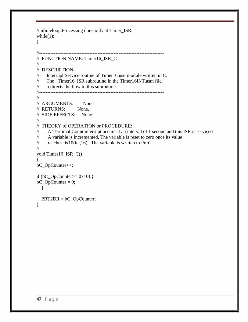
//infinteloop.Processing done only at Timer_ISR.
while(1);
}
//-----------------------------------------------------------------------------
// FUNCTION NAME: Timer16_ISR_C
//
// DESCRIPTION:
// Interrupt Service routine of Timer16 usermodule written in C.
// The _Timer16_ISR subroutine In the Timer16INT.asm file,
// redirects the flow to this subroutine.
//-----------------------------------------------------------------------------
//
// ARGUMENTS: None
// RETURNS: None.
// SIDE EFFECTS: None.
//
// THEORY of OPERATION or PROCEDURE:
// A Terminal Count interrupt occurs at an interval of 1 second and this ISR is serviced
// A variable is incremented. The variable is reset to zero once its value
// reaches 0x10(ie.,16). The variable is written to Port2.
//
void Timer16_ISR_C()
{
bC_OpCounter++;
if (bC_OpCounter>= 0x10) {
bC_OpCounter = 0;
}
PRT2DR = bC_OpCounter;
}

48 | P a g e
WEEK-12 Experiment No.12
Aim : Write a program to interface stepper motor
Apparatus: 1. PSOC Board
2. 5V Adapter
3. Parallel Cable
4. PSOC designer
Source code:
#include <m8c.h> // part specific constants and macros
#include "PSoCAPI.h" // PSoC API definitions for all User Modules
#pragma interrupt_handler RX8_1_ISR_C
// in this code default mode is normal_sequence_forward is repersents the charcter 'a'
voidmotor_delay(int);
voidnormal_sequence_forward(void);
voidnormal_sequence_reverse(void);
int flag=1;
BYTE receiver_data;
int ds=15; //ds means default speed
chardefault_mode='a';
chardefault_direction='f';
voiddelay_sec(int sec)
{
inti,j,secd;
for (secd=0;secd<=sec;secd++)
for(i=0;i<=2;i++)
for (j= 0;j<=20480;j++)
{
}
}
voidmotor_delay(int sec)
{
inti,j,secd;
for (secd=0;secd<=sec;secd++)
for(i=0;i<=4;i++)
for (j= 0;j<=400;j++)
{
}

49 | P a g e
}
//----------------------------------------------------------------------------------//
voidnormal_sequence_reverse(){
while(1){
if(flag){
PRT0DR=0x05;
motor_delay(ds);
PRT0DR=0x09;
motor_delay(ds);
PRT0DR=0x0a;
motor_delay(ds);
PRT0DR=0x06;
motor_delay(ds);
}
else
break;
}
}
//----------------------------------------------------------------------------------//
voidnormal_sequence_forward(){
while(1){
if(flag){
PRT0DR=0x05;
motor_delay(ds);
PRT0DR=0x06;
motor_delay(ds);
PRT0DR=0x0a;
motor_delay(ds);
PRT0DR=0x09;
motor_delay(ds);
}
else
break;
}
}
void main()
{
inti,j;
M8C_EnableGInt; // enable Globale interrupts
RX8_1_EnableInt();
RX8_1_Start(RX8_1_PARITY_NONE);
TX8_1_Start(TX8_PARITY_NONE);

50 | P a g e
LCD_1_Start();
TX8_1_CPutString("\r\n This is tha Stepper Motor interfacing program");
TX8_1_CPutString("\r\n Read the follwoinhinstrcutions:\r\n");
TX8_1_CPutString("\r\n 1. Normal sequence = 'a'");
TX8_1_CPutString("\r\n 4. Forward directiom = 'f'");
TX8_1_CPutString("\r\n 5. Reverse directiom = 'r'");
TX8_1_CPutString("\r\n 8. Stop the motor = 'd'");
TX8_1_CPutString("\r\n\r\n -----------------------------------------------\r\n\r\n");
while(1){
if(receiver_data=='f' || receiver_data=='r')
default_direction=receiver_data;
else if(receiver_data=='a' || receiver_data=='d' )
default_mode=receiver_data;
flag=1;
switch(default_mode){
case 'a': LCD_1_Position(0,0);
LCD_1_PrCString("Normal Sequence");
LCD_1_Position(1,0);
if(default_direction=='f'){
LCD_1_PrCString("Forward mode");
TX8_1_CPutString("\r\n This is the Normal Sequence Forward Mode\r\n");
normal_sequence_forward();
}
else if(default_direction=='r'){
LCD_1_PrCString("Reverse mode");
TX8_1_CPutString("\r\n This is the Normal Sequence Reverse Mode\r\n");
normal_sequence_reverse();
}
break;
case 'd': LCD_1_Control(0x01);
LCD_1_Position(0,0);
TX8_1_CPutString("\r\n The system is stop mode\r\n");
LCD_1_PrCString("System stop");
while(1){
if(flag)
PRT0DR=0x00;
else

51 | P a g e
break;
}
break;
}
}
}
//RX8 Interrupr service routine
void RX8_1_ISR_C()
{
flag=0;
receiver_data = RX8_1_bReadRxData();
return;
}