emc array group and srdf-a reporting in rmf magic · pdf fileapplication note rmf magic 5.1.0:...
TRANSCRIPT

Application NoteRMF Magic 5.1.0:
EMC Array Group and EMC SRDF/A Reporting
July 2009
Summary: This Application Note describes the new functionality in
RMF Magic 5.1 that enables more effective monitoring of EMC storage systems and SRDF/A.
www.intellimagic.net www.intellimagic.net

Application Note RMF Magic 5.1.0: EMC Array Group and EMC SRDF/A Reporting
© 2009 IntelliMagic BV ii
This Application Note was prepared by: IntelliMagic BV Leiden, The Netherlands Phone: +31 71 579 6000 IntelliMagic Inc Texas, USA Phone: 1 214 432 7920 Email: [email protected] Web: www.intellimagic.net Disclaimer RMF Magic analyzes RMF data and provides estimates for workload parameters based on this information. IntelliMagic products analyze measurement data and provide estimates for workload parameters based on this information. However, IntelliMagic does not guarantee the correctness of these numbers, and therefore any sizing based on the results remains the responsibility of the user. Support Please direct requests for information to [email protected] Trademarks All trademarks and registered trademarks are the property of their respective owners. © 2009 IntelliMagic BV

Application Note RMF Magic 5.1.0: EMC Array Group and EMC SRDF/A Reporting
© 2009 IntelliMagic BV iii
Table of contents Introduction........................................................................................................................................... 1 EMC Array Group Level reporting................................................................................................. 2
Dashboard Viewer .........................................................................................................................6 SRDF/A Reporting ............................................................................................................................... 8 Appendix 1: SRDF/A variables in reporting............................................................................12

Application Note RMF Magic 5.1.0: EMC Array Group and EMC SRDF/A Reporting
© 2009 IntelliMagic BV iv
Table of Figures Figure 1: Sample (partial) SQ MIRROR output for RAID-10 (top) and RAID-5 (bottom) devices. .................................................................................................................................................................2 Figure 2: RAID-5 Array sample configuration. RMF Magic refers to the array with generated number 0040, EMC uses the Device Adapter / Interface position notation. .......3 Figure 3: Specify that the SQ MIRROR information is available.......................................................3 Figure 4: Sample log when not CUU addresses are recognized.. ................................................... 4 Figure 5: Sample EMC Configuration report from the reduce log (SYSPRINT DDname). ...... 4 Figure 6: Selecting the array group report: Select Rank on Breakdown Charts for the disk storage system that you want to study....................................................................................................5 Figure 7: Sample report for array group activity highlighting some heavily used array groups (the lines that are shown in bold) ............................................................................................. 6 Figure 8: You can drill down in the Dashboard via the array groups to the z/OS volumes. Note that the EMC array information is shown integrated with the z/OS performance metrics. .................................................................................................................................................................7 Figure 9: Selecting the SRDF/A Charts. The Copy Services tab and SRDF/A selection is available at all aggregation levels............................................................................................................. 9 Figure 10: Average Cycle time for all disk storage systems summarized per session .......... 10 Figure 11: Maximum Cycle Time per session per RMF interval for one disk storage system............................................................................................................................................................................... 10 Figure 12: Maximum Cycle Size per session per RMF interval for one disk storage system. 11 Figure 13: Write activity is reported per disk storage system. .........................................................11

Application Note RMF Magic 5.1.0: EMC Array Group and EMC SRDF/A Reporting
© 2009 IntelliMagic BV 1
Introduction RMF Magic is a Storage Performance Management product designed to help you manage your storage systems more cost effectively. Version 5.1 introduces two important new features for EMC customers:
Visibility into the EMC back-end at the array group level from SMF records: the ability to report performance per array group for RAID-10 and RAID-5 configurations. RMF Magic uses reports from the SRDF Host Component to obtain the configuration information to complement the RMF records. With this support you will be able to determine whether or not the back-end devices are creating performance problems. If so, you can move one or more of the very busy logical volumes to another array group.
For hardware from IBM , HDS and HP, the same reports can be created directly off the RMF records without the need to additional input data.
Support for the EMC SRDF/A custom SMF record, allowing you to track the
SRDF/A delta set size and cycle time. With this support, EMC users can graphically monitor SRDF/A health and see performance issues develop before they cause SRDF/A sessions to drop.
With the addition of these new functions, combined with the existing SMF/RMF data, you can more effectively monitor your EMC Storage systems. In this Application Note both features are introduced. For reference information on RMF Magic, please refer to the regular RMF Magic Reference Manual. For more information on planning and monitoring SRDF/A, please refer to our white paper “Using RMF Magic to Plan and Monitor an EMC SRDF/A Configuration”.
Application Note RMF Magic 5.1.0: EMC Array Group and EMC SRDF/A Reporting
© 2009 IntelliMagic BV 2
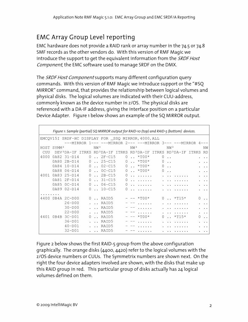
EMC Array Group Level reporting EMC hardware does not provide a RAID rank or array number in the 74.5 or 74.8 SMF records as the other vendors do. With this version of RMF Magic we introduce the support to get the equivalent information from the SRDF Host Component, the EMC software used to manage SRDF on the DMX. The SRDF Host Component supports many different configuration query commands. With this version of RMF Magic we introduce support or the “#SQ MIRROR” command, that provides the relationship between logical volumes and physical disks. The logical volumes are indicated with their CUU-address, commonly known as the device number in z/OS. The physical disks are referenced with a DA-IF address, giving the interface position on a particular Device Adapter. Figure 1 below shows an example of the SQ MIRROR output.
Figure 1: Sample (partial) SQ MIRROR output for RAID-10 (top) and RAID-5 (bottom) devices.
EMCQV15I SRDF-HC DISPLAY FOR _SSQ MIRROR,4000,ALL ---MIRROR 1--- ---MIRROR 2--- ---MIRROR 3--- ---MIRROR 4---HOST SYMM³ NW³ NW³ NW³ NW CUU DEV³DA-IF ITRKS RD³DA-IF ITRKS RD³DA-IF ITRKS RD³DA-IF ITRKS RD4000 0A82 31-D14 0 .. 2F-C15 0 .. *T00* 0 .. . .. 0A80 2B-D14 0 .. 25-C15 0 .. *T00* 0 .. . .. 0A84 10-D14 0 .. 02-C15 0 .. *T00* 0 .. . .. 0A88 06-D14 0 .. 0C-C15 0 .. *T00* 0 .. . ..4001 0A83 25-D14 0 .. 2B-C15 0 .. ...... . .. ...... . .. 0A81 2F-D14 0 .. 31-C15 0 .. ...... . .. ...... . .. 0A85 0C-D14 0 .. 06-C15 0 .. ...... . .. ...... . .. 0A89 02-D14 0 .. 10-C15 0 .. ...... . .. ...... . .......... 4400 0B4A 2C-D00 0 .. RAID5 - -- *T00* 0 .. *T15* 0 .. 26-D00 . .. RAID5 - -- ...... . .. ...... . .. 30-D00 . .. RAID5 - -- ...... . .. ...... . .. 22-D00 . .. RAID5 - -- ...... . .. ...... . ..4401 0B4B 3C-D01 0 .. RAID5 - -- *T00* 0 .. *T15* 0 .. 36-D01 . .. RAID5 - -- ...... . .. ...... . .. 40-D01 . .. RAID5 - -- ...... . .. ...... . .. 32-D01 . .. RAID5 - -- ...... . .. ...... . ..
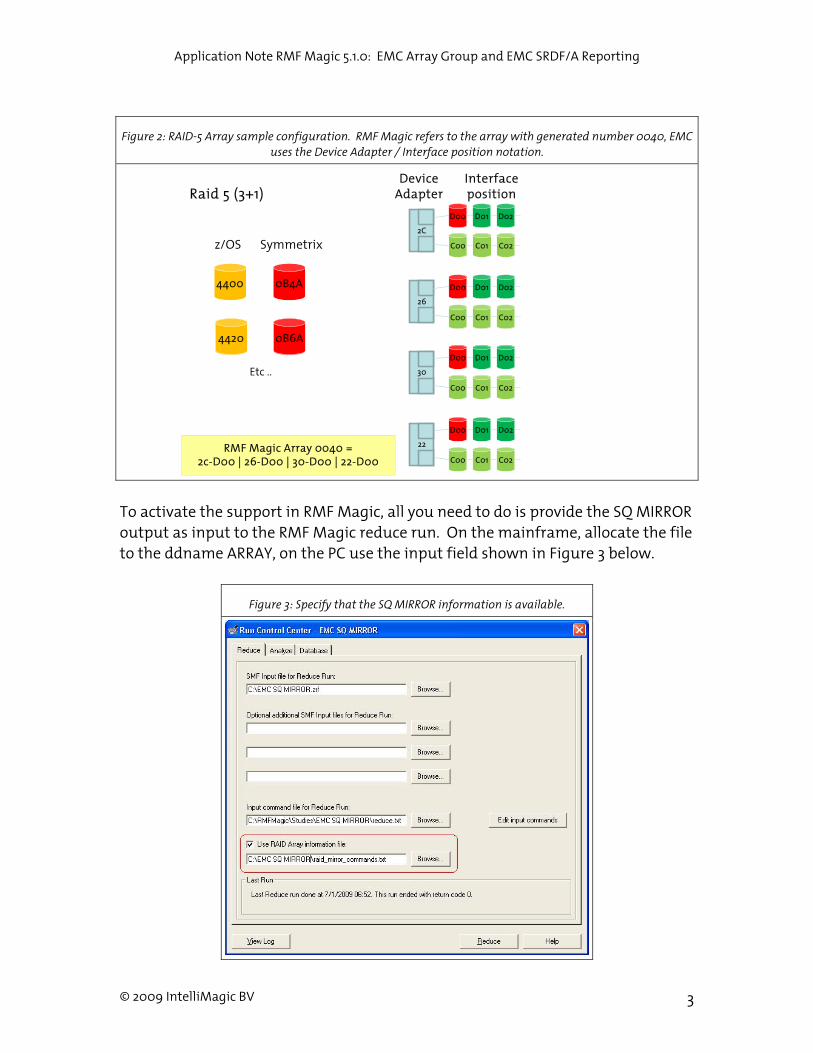
Figure 2 below shows the first RAID-5 group from the above configuration graphically. The orange disks (4400, 4420) refer to the logical volumes with the z/OS device numbers or CUUs. The Symmetrix numbers are shown next. On the right the four device adapters involved are shown, with the disks that make up this RAID group in red. This particular group of disks actually has 24 logical volumes defined on them.
Application Note RMF Magic 5.1.0: EMC Array Group and EMC SRDF/A Reporting
© 2009 IntelliMagic BV 3
Figure 2: RAID-5 Array sample configuration. RMF Magic refers to the array with generated number 0040, EMC uses the Device Adapter / Interface position notation.
To activate the support in RMF Magic, all you need to do is provide the SQ MIRROR output as input to the RMF Magic reduce run. On the mainframe, allocate the file to the ddname ARRAY, on the PC use the input field shown in Figure 3 below.
Figure 3: Specify that the SQ MIRROR information is available.
4400 0B4A D00 D01 D02
26
C00 C01 C02
30
D00
C00
D01
C01
D02
C02
22
D00
C00
D01
C01
D02
C02
z/OS Symmetrix
Device AdapterRaid 5 (3+1)
2C
D00 D01 D02
C00 C01 C02
RMF Magic Array 0040 = 2c-D00 | 26-D00 | 30-D00 | 22-D00
Interface position
4420 0B6A
Etc ..

Application Note RMF Magic 5.1.0: EMC Array Group and EMC SRDF/A Reporting
© 2009 IntelliMagic BV 4
RMF Magic analyzes the SQ MIRROR output, and identifies which logical volumes share a group of physical disks. The physical disks are grouped into RAID-5 or RAID-10 arrays, and RMF Magic assigns array group numbers to these groups. The array group numbers are subsequently used in the reporting. It should be noted that the array group numbers are not used by any EMC tool, they are strictly for use in RMF Magic.The Reduce log shows how the groups are assigned, such that you can correlate the EMC and RMF Magic reports if desired. If RMF Magic cannot find the CUU addresses in the RMF 74.1 records from the first interval, it will issue warning RMF0233 as shown in Figure 4 below. In that case you need to specify in which DSS the address occurs. Please refer to the section “3.3.12 EMC Array Groups” in the RMF Magic reference manual for the commands to use in that case. The errors can also be avoided by making sure that data from all systems is available for the first interval.
Figure 4: Sample log when not CUU addresses are recognized..
RMF0230N 00 Reading Array information from file C:\rmfdata\devices.D2675.txt. RMF0233I 04 Command " EMCQV19I SRDF-HC DISPLAY FOR (10) :SQ RAID5,3A00,192" does not have a DSS associated with it. RMF0233I 04 Command " EMCQV19I SRDF-HC DISPLAY FOR (11) :SQ RAID5,3B00,192" doesn't have a DSS associated with it. RMF0233I 04 Command " EMCQV19I SRDF-HC DISPLAY FOR (12) :SQ RAID5,3C00,192" doesn't have a DSS associated with it. ………. RMF0233I 04 Command " EMCQV19I SRDF-HC DISPLAY FOR (17) :SQ RAID5,7900,192" doesn't have a DSS associated with it. RMF0232N 00 Read 384 device rows from Array information file.
Figure 5: Sample EMC Configuration report from the reduce log (SYSPRINT DDname).
D I S K S U B S Y S T E M C O N F I G U R A T I O N RMF Magic Reduce Disk Subsystem EMC-02675 +-----+-------+---------------------+----------------------------------------+|Array|RAID |DMC DA-IF addresses |z/OS Device numbers (CUU) ||Group|type | | |+-----+-------+---------------------+----------------------------------------+|00 |RAID5 |01-C14, 0F-C14, |3200, 3234, 32a3, 3352, 3401, 3470, || | |22-D14, 30-D14 |351f, 358e, 363b, 36aa, 3759, 3808, || | | |3877, 3926, 3995, 3a44, 3ab3, 3b40, || | | |3baf, 3c5e, 3d0d, 3d7c, 3e2b, 3e9a, || | | |3f49, 3fb8, 783d, 78ac, 795b, 7a0a, || | | |7a79, 7b62, 7c11, 7c80, 7d2f, 7d9e, || | | |7e67, 7f16, 7f85, 9664, 9713, 9782, || | | |9831, 98a0, 991a, 9989, 9a38, 9aa7, || | | |9b56, 9c4a, 9cb9, 9d68, b728, b797, || | | |b94d, b9bc, ba6b, bb34, bba3, bc2c, bc9b||01 |RAID5 |12-D13, 20-D13, |3201, 321d, 328c, 333b, 33aa, 3459, || | |31-C13, 3F-C13 |3508, 3577, 3648, 36b7, 3766, 3815, || | | |3884, 3933, 39a2, 3a51, 3b00, 3b6f, |

Application Note RMF Magic 5.1.0: EMC Array Group and EMC SRDF/A Reporting
© 2009 IntelliMagic BV 5
| | | |3c1e, 3c8d, 3d3c, 3dab, 3e5a, 3f09, || | | |3f78, 7826, 7895, 7944, 79b3, 7a62, || | | |7b00, 7b6f, 7c1e, 7c8d, 7d3c, 7dab, || | | |7e27, 7e96, 7f45, 7fb4, 964d, 96bc, || | | |976b, 981a, 9889, 9927, 9996, 9a45, || | | |9ab4, 9b63, 9c39, 9ca8, 9d57, b711, || | | |b780, b95a, ba09, ba78, bb63, bc1b, bc8a| ........... +-----+-------+---------------------+----------------------------------------+
In this report, the DA-IF notation is the method EMC uses to identify an individual disk drive. In this RAID-5 configuration, each array group uses 4 disks. With this information, RMF Magic can now create Array group (Rank) Reports that show the activity on each array group. These reports are created from the Breakdown Charts tab as shown below.
Figure 6: Selecting the array group report: Select Rank on Breakdown Charts for the disk storage system that you want to study.
Using these reports you can assess if the performance is about the same for each array group, and in particular whether there are any overloaded groups that may cause delays in the back-end. The following chart shows a configuration where array imbalance did cause performance issues for the applications.

Application Note RMF Magic 5.1.0: EMC Array Group and EMC SRDF/A Reporting
© 2009 IntelliMagic BV 6
Figure 7: Sample report for array group activity highlighting some heavily used array groups (the lines that are shown in bold)
Dashboard Viewer The array information is available in the Dashboard detail viewer as well, allowing you to drill down from the DSS level down to the volumes on the arrays. The dialog below shows an example of this process. On top, the list of intervals is shown for disconnect time. After clicking the button ‘Array Group Detail’, the middle section of the dialog is filled with the array group information. Finally, upon clicking the ‘Active Volumes in Array/LSS’ button the most active volumes on the selected array group are shown. With this dialog you can quickly identify the most active array groups, and see which volumes cause the activity.
All activity: Read (MB/s) by Rank/Pool
0
20
40
60
80
100
120
140
06:4
5:00
08:4
5:00
10:4
5:00
12:4
5:00
14:4
5:00
16:4
5:00
18:4
5:00
20:4
5:00
22:4
5:00
00:4
5:00
02:4
5:00
04:4
5:00
MB
/s

Application Note RMF Magic 5.1.0: EMC Array Group and EMC SRDF/A Reporting
© 2009 IntelliMagic BV 7
Figure 8: You can drill down in the Dashboard via the array groups to the z/OS volumes. Note that the EMC array information is shown integrated with the z/OS performance metrics.

Application Note RMF Magic 5.1.0: EMC Array Group and EMC SRDF/A Reporting
© 2009 IntelliMagic BV 8
SRDF/A Reporting The SRDF/A reporting charts the information from the SRDF/A sessions for each EMC storage system based on the SMF records created by the EMC SRDF software. RMF Magic summarizes the information from the EMC records on an RMF interval basis, to make it easier to correlate the SRDF/A information with the RMF data fields such as I/O rate and response time. The following commands must be used to request processing of these records. Note that the SMF record is a ‘user SMF record’, for which your installation can choose the record number between 128 and 256. If you do not use the default record number 206, you need to set the actual number used as shown below.
* request SRDFA record processing COLLECT SRDFA; * specify SMF record number used if not equal to 206 COLLECT SMFRECSRDFA=n;
Please note that you must also update the SMF and SORT JCL to keep the SRDF/A records in the input file. It recommended that you merge the SRDF/A records with the SMF 42 records in one data set. Apart from these commands in reduce there are no setup requirements. The reports are available in the report control center on the Copy Services Tab as shown in Figure 9. Reports can be created from any of the detail levels: daily, weekly, monthly (per interval) or yearly (per shift).
Application Note RMF Magic 5.1.0: EMC Array Group and EMC SRDF/A Reporting
© 2009 IntelliMagic BV 9
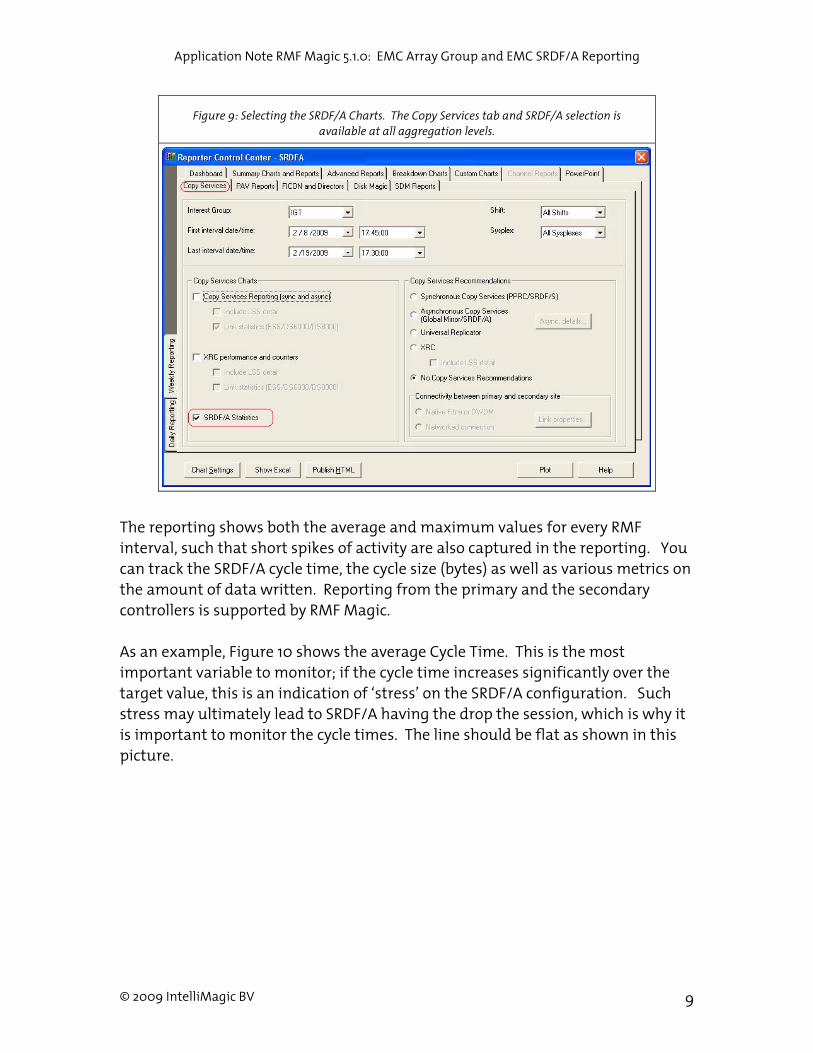
Figure 9: Selecting the SRDF/A Charts. The Copy Services tab and SRDF/A selection is available at all aggregation levels.
The reporting shows both the average and maximum values for every RMF interval, such that short spikes of activity are also captured in the reporting. You can track the SRDF/A cycle time, the cycle size (bytes) as well as various metrics on the amount of data written. Reporting from the primary and the secondary controllers is supported by RMF Magic. As an example, Figure 10 shows the average Cycle Time. This is the most important variable to monitor; if the cycle time increases significantly over the target value, this is an indication of ‘stress’ on the SRDF/A configuration. Such stress may ultimately lead to SRDF/A having the drop the session, which is why it is important to monitor the cycle times. The line should be flat as shown in this picture.

Application Note RMF Magic 5.1.0: EMC Array Group and EMC SRDF/A Reporting
© 2009 IntelliMagic BV 10
Figure 10: Average Cycle time for all disk storage systems summarized per session
Cycle Time (sec) for all DSSs
0
5
10
15
20
25
30
35
sec
0002
0003
0020
RMF Magic also reports the maximum cycle time found in the data, as it provided a more accurate indication of potential problems. Figure 11 below shows the maximum values for the same set of data. As you can see, there are actually some delays, but no cycle was ever longer than 45 seconds.
Figure 11: Maximum Cycle Time per session per RMF interval for one disk storage system.
Max Cycle Time (s) by SRDF/A Session for EMC-12345
0
5
10
15
20
25
30
35
40
45
s
0002
0003
0020
In this particular configuration, the higher cycle times are caused by peaks in the write activity and therefore cycle size:
Application Note RMF Magic 5.1.0: EMC Array Group and EMC SRDF/A Reporting
© 2009 IntelliMagic BV 11
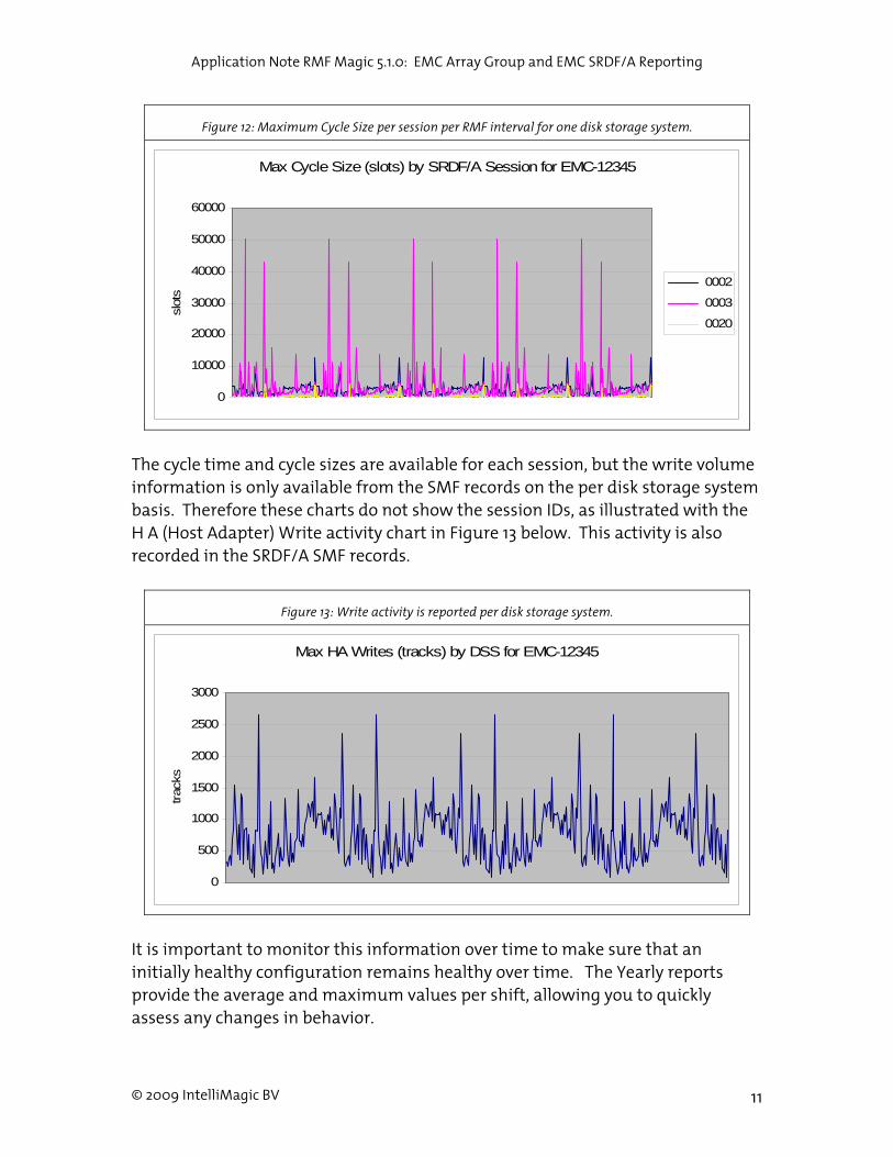
Figure 12: Maximum Cycle Size per session per RMF interval for one disk storage system.
Max Cycle Size (slots) by SRDF/A Session for EMC-12345
0
10000
20000
30000
40000
50000
60000
slot
s
0002
0003
0020
The cycle time and cycle sizes are available for each session, but the write volume information is only available from the SMF records on the per disk storage system basis. Therefore these charts do not show the session IDs, as illustrated with the H A (Host Adapter) Write activity chart in Figure 13 below. This activity is also recorded in the SRDF/A SMF records.
Figure 13: Write activity is reported per disk storage system.
Max HA Writes (tracks) by DSS for EMC-12345
0
500
1000
1500
2000
2500
3000
trac
ks
It is important to monitor this information over time to make sure that an initially healthy configuration remains healthy over time. The Yearly reports provide the average and maximum values per shift, allowing you to quickly assess any changes in behavior.
Application Note RMF Magic 5.1.0: EMC Array Group and EMC SRDF/A Reporting
© 2009 IntelliMagic BV 12
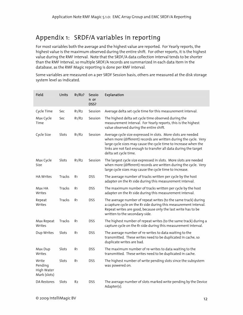
Appendix 1: SRDF/A variables in reporting For most variables both the average and the highest value are reported. For Yearly reports, the highest value is the maximum observed during the entire shift. For other reports, it is the highest value during the RMF interval. Note that the SRDF/A data collection interval tends to be shorter than the RMF interval, so multiple SRDF/A records are summarized in each data item in the database, as the RMF Magic reporting is done per RMF interval.
Some variables are measured on a per SRDF Session basis, others are measured at the disk storage system level as indicated.
Field Units R1/R2? Session or DSS?
Explanation
Cycle Time Sec R1/R2 Session Average delta set cycle time for this measurement interval.
Max Cycle Time
Sec R1/R2 Session The highest delta set cycle time observed during the measurement interval. For Yearly reports, this is the highest value observed during the entire shift.
Cycle Size Slots R1/R2 Session Average cycle size expressed in slots. More slots are needed when more (different) records are written during the cycle. Very large cycle sizes may cause the cycle time to increase when the links are not fast enough to transfer all data during the target delta set cycle time.
Max Cycle Size
Slots R1/R2 Session The largest cycle size expressed in slots. More slots are needed when more (different) records are written during the cycle. Very large cycle sizes may cause the cycle time to increase.
HA Writes Tracks R1 DSS The average number of tracks written per cycle by the host adapter on the R1 side during this measurement interval.
Max HA Writes
Tracks R1 DSS The maximum number of tracks written per cycle by the host adapter on the R1 side during this measurement interval.
Repeat Writes
Tracks R1 DSS The average number of repeat writes (to the same track) during a capture cycle on the R1 side during this measurement interval. Repeat writes are good, because only the last write has to be written to the secondary side.
Max Repeat Writes
Tracks R1 DSS The highest number of repeat writes (to the same track) during a capture cycle on the R1 side during this measurement interval.
Dup Writes Slots R1 DSS The average number of re-writes to data waiting to the transmitted. These writes need to be duplicated in cache, so duplicate writes are bad.
Max Dup Writes
Slots R1 DSS The maximum number of re-writes to data waiting to the transmitted. These writes need to be duplicated in cache.
Write Pending High Water Mark (slots)
Slots R1 DSS The highest number of write pending slots since the subsystem was powered on.
DA Restores Slots R2 DSS The average number of slots marked write pending by the Device Adapter(s).

Application Note RMF Magic 5.1.0: EMC Array Group and EMC SRDF/A Reporting
© 2009 IntelliMagic BV 13
Field Units R1/R2? Session or DSS?
Explanation
Max DA Restores
Slots R2 DSS The highest number of slots marked write pending by the Device Adapter(s).
DA Merges Slots R2 DSS The average number of merges, ie updates to slots that were already marked write pending.
Max DA Merges
Slots R2 DSS The maximum number of merges, ie updates to slots that were already marked write pending.
Restore Time
Slots R2 Session The average restore time observed on the secondary subsystem.
Max Restore Time
Slots R2 Session The maximum restore time observed on the secondary subsystem.