emc host connectivity guide for oracle solaris · setting up solaris cluster data service for...
TRANSCRIPT
Dell EMC Host Connectivity Guide for Oracle Solaris
P/N 300-000-607REV 55
Published: February 2019

Copyright © 2007 – 2018 Dell Inc. or its subsidiaries. All rights reserved.
Dell believes the information in this publication is accurate as of its publication date. The information is subject to change without notice.
THE INFORMATION IN THIS PUBLICATION IS PROVIDED "AS IS." EMC CORPORATION MAKES NO REPRESENTATIONS OR WARRANTIES OF ANY KIND WITH RESPECT TO THE INFORMATION IN THIS PUBLICATION, AND SPECIFICALLY DISCLAIMS IMPLIED WARRANTIES OF MERCHANTABILITY OR FITNESS FOR A PARTICULAR PURPOSE.
Use, copying, and distribution of any EMC software described in this publication requires an applicable software license.
DELL EMC, and the EMC logo are registered trademarks or trademarks of Dell Inc. or its subsidiaries. All other trademarks used herein are the property of their respective owners.
For the most up-to-date regulator document for your product line, go to EMC Online Support (https://support.emc.com).
Dell EMC Host Connectivity Guide for Oracle Solaris2
CONTENTS
Preface ....................................................................................................................................... 13
Part 1 Connecting Solaris to Dell EMC Storage
Chapter 1 Solaris Operating System
Solaris operating system overview........................................................................ 20Multipathing software ........................................................................................... 21
MPxIO/STMS ................................................................................................ 21Dell EMC PowerPath ..................................................................................... 21Veritas DMP................................................................................................... 21
Volume managers on a Solaris OS ........................................................................ 22Solaris Volume Manager (SVM) ................................................................... 22Solaris Zettabyte file system/zpool ................................................................ 22Veritas Volume Manager ............................................................................... 22
HBAs and drivers .................................................................................................. 24Host configuration with Emulex HBAs ......................................................... 24emlxs driver.................................................................................................... 25Host configuration with QLogic HBAs ......................................................... 25qlc driver ........................................................................................................ 26Host configuration with Oracle HBAs ........................................................... 26
Useful Solaris utilities and functions..................................................................... 28System and error messages.................................................................................... 29
Chapter 2 Solaris Supported Connectivity Protocols
Addressing Dell EMC storage devices using Fibre Channel ................................ 32Arbitrated loop addressing ............................................................................. 32Fabric addressing............................................................................................ 32
Solaris SPARC Fibre Channel environment.......................................................... 34Software ......................................................................................................... 34
Solaris connection over iSCSI............................................................................... 35Software ......................................................................................................... 35Addressing...................................................................................................... 35Configuring Solaris iSCSI initiators .............................................................. 35Solaris iSCSI/Symmetrix case studies ........................................................... 35Symmetrix configuration................................................................................ 36Solaris 10 host configuration.......................................................................... 37Solaris 11 host configuration.......................................................................... 38
Solaris Connection over FCoE .............................................................................. 40Benefits........................................................................................................... 41Enabling technologies .................................................................................... 42Converged Network Adapter ......................................................................... 42Fibre Channel Forwarder ............................................................................... 42Priority Flow Control and PAUSE................................................................. 42Data Center Bridging (lossless Ethernet) ....................................................... 44Data Center Bridging eXchange .................................................................... 44
Configuring the Solaris host.................................................................................. 46
Dell EMC Host Connectivity Guide for Oracle Solaris 3
Contents
Chapter 3 Solaris Virtualization
Solaris Zones ......................................................................................................... 48Oracle VM Server for SPARC............................................................................... 49
Chapter 4 Solaris Cluster
Solaris Cluster overview........................................................................................ 52What is Solaris Cluster? ................................................................................. 52
Hardware components ........................................................................................... 53Cluster nodes .................................................................................................. 53Storage............................................................................................................ 53Cluster interconnect........................................................................................ 53
Software components for cluster servers............................................................... 54Supported software versions for Solaris Cluster ............................................ 54
Solaris Cluster configuration examples................................................................. 55Key Solaris Cluster concepts................................................................................. 59
Cluster Membership Monitor (CMM)............................................................ 59Cluster Configuration Repository (CCR)....................................................... 59Global devices ................................................................................................ 59Device ID (DID)............................................................................................. 60Global namespace .......................................................................................... 60Cluster file systems ........................................................................................ 60Solaris Cluster data services........................................................................... 60Resource groups ............................................................................................. 61Quorum and failure fencing ........................................................................... 61
Important Solaris Cluster utilities.......................................................................... 62scinstall........................................................................................................... 62clsetup............................................................................................................. 62scconf ............................................................................................................. 62scdidadm......................................................................................................... 63scgdevs ........................................................................................................... 63scstat ............................................................................................................... 63scswitch .......................................................................................................... 64scshutdown ..................................................................................................... 64
Configuring VMAX/PowerMax with Solaris Cluster ........................................... 65VMAX/PowerMax setup for Solaris Cluster ................................................. 65FA port sharing............................................................................................... 65
Configuring VNX/Unity series with Solaris Cluster............................................. 66Installation guidelines .................................................................................... 66Solaris Cluster servers.................................................................................... 66
Examples ............................................................................................................... 67Setting up a Solaris Cluster quorum device on Dell EMC storage ................ 67Creating a cluster file system ......................................................................... 67Configuring the Solaris Cluster Data Service for Network File System (NFS) 68Setting up Solaris Cluster data service for RAC............................................ 69General setup guidelines for configuring Solaris Cluster OPS/RAC data service 70
Chapter 5 Provisioning from Dell EMC storage to Solaris
Configuring MPxIO for DELL EMC storage devices........................................... 74Creating and mounting a file system..................................................................... 75
Intent logging ................................................................................................. 75VxFS and VxVM intent logging .................................................................... 75SVM intent logging........................................................................................ 75UFS on raw devices........................................................................................ 76
4 Dell EMC Host Connectivity Guide for Oracle Solaris
Contents
VxFS on raw device ....................................................................................... 76UFS on SVM device ...................................................................................... 77VxFS on SVM device .................................................................................... 77UFS on VxVM devices .................................................................................. 78VxFS on VxVM devices ................................................................................ 79
Volume Manager feature functionality .................................................................. 81Thin Reclamation (VxVM/ZFS) .................................................................... 81SmartMove (VxVM) ...................................................................................... 81Online Volume Expansion ............................................................................. 82
Part 2 Solaris and Dell EMC Storage
Chapter 6 Storage Virtual Provisioning
Virtual Provisioning on Symmetrix....................................................................... 86Terminology ................................................................................................... 87Thin device..................................................................................................... 88
Implementation considerations.............................................................................. 90Over-subscribed thin pools............................................................................. 90Thin-hostile environments.............................................................................. 91Pre-provisioning with thin devices in a thin hostile environment.................. 91Host boot/root/swap/dump devices positioned on Symmetrix virtual provisioning (tdev) devices 92Cluster configurations .................................................................................... 93
Operating system characteristics ........................................................................... 94
Chapter 7 Solaris and VMAX/PowerMax Connectivity
Solaris SPARC and VMAX/PowerMax environment........................................... 96Hardware connectivity ................................................................................... 96Solaris operating system................................................................................. 96Boot device support........................................................................................ 96VMAX/PowerMax configuration .................................................................. 96System settings............................................................................................... 96
Understanding persistent binding in a fabric environment.................................... 98What happens without persistent binding ...................................................... 98Binding models .............................................................................................. 98
VMAX/PowerMax connection over iSCSI ........................................................... 99Hardware ........................................................................................................ 99Configuring VMAX/PowerMax iSCSI director ............................................ 99
...................................................................................................Running inquiry 100VMAX/PowerMax SPC-2 director bit considerations ........................................ 101VMAX/PowerMax new features......................................................................... 103
SRDF Metro ................................................................................................. 103NDM (Non-Disruptive Migration)............................................................... 103ALUA support with Mobility ID (MID) ...................................................... 103
Host configuration with Emulex HBAs .............................................................. 104Host configuration with QLogic HBAs............................................................... 105
Chapter 8 Solaris and VNX/Unity Connectivity
Solaris in a VNX/Unity series environment ........................................................ 108Host connectivity.......................................................................................... 108Boot device support...................................................................................... 108Logical devices............................................................................................. 108
VNX/Unity series configuration.......................................................................... 109
Dell EMC Host Connectivity Guide for Oracle Solaris 5
Contents
VNX/Unity failover mode settings .............................................................. 109VNX/Unity series and Solaris FC environment .................................................. 110
Software ....................................................................................................... 110Addressing.................................................................................................... 110System settings............................................................................................. 110Configuring MPxIO for VNX/Unity series devices..................................... 111
Making LUNs available to Solaris ...................................................................... 112Specifying Solaris disk names for LUNs ..................................................... 112Partitioning and labeling LUNs.................................................................... 112Making file systems on partitions ................................................................ 113Mounting file systems .................................................................................. 113Verifying that the server can see its LUNs .................................................. 113
Methods for reassigning LUN ownership ........................................................... 115Failover using PowerPath............................................................................. 115
Updating disk names after reassigning LUNs ..................................................... 116Updating disk names if an SP fails............................................................... 116Updating disk names if you manually change LUN ownership................... 116
Examples — Manually reassigning LUNs .......................................................... 117Unshared direct single server configuration................................................. 117Reassigning LUN ownership using Unisphere/Navisphere Manager.......... 118Sample unshared direct dual-server configuration....................................... 119Reassigning LUN ownership using Unisphere/Navisphere Manager.......... 120
Chapter 9 Solaris and XtremIO Storage Connectivity
Solaris and Dell EMC XtremIO environment ..................................................... 122Hardware connectivity ................................................................................. 122Solaris operating system............................................................................... 122Boot device support...................................................................................... 122Solaris host system settings.......................................................................... 122Configuring XtremIO................................................................................... 124
Oracle VM Server for SPARC............................................................................. 125Veritas Volume Manager ..................................................................................... 126Solaris and XtremIO over Fibre Channel ............................................................ 127
Software ....................................................................................................... 127Addressing.................................................................................................... 127Prerequisites ................................................................................................. 127
Solaris and XtremIO over iSCSI ......................................................................... 128Hardware ...................................................................................................... 128Software ....................................................................................................... 128Addressing.................................................................................................... 128Configuring Solaris iSCSI initiators ............................................................ 128Configuring XtremIO iSCSI targets............................................................. 128Solaris iSCSI/XtremIO case study ............................................................... 128
Multipathing software configuration................................................................... 132Configuring Solaris Native Multipathing STMS ......................................... 132Configuring Veritas Dynamic MultiPathing (DMP).................................... 132
Configuring PowerPath Multipathing ................................................................. 134Post configuration using the XtremIO cluster ..................................................... 135
Disk formatting ............................................................................................ 135Disk alignment ............................................................................................. 135Creating a file system................................................................................... 136
6 Dell EMC Host Connectivity Guide for Oracle Solaris

Contents
Chapter 10 Solaris and VPLEX connectivity
VPLEX overview ................................................................................................ 138Prerequisites ........................................................................................................ 139Configuring Fibre Channel HBAs with VPLEX................................................. 140
Prerequisites ................................................................................................. 140Setting execution throttle for QLogic........................................................... 140Setting target queue depth for Emulex......................................................... 141
Provisioning and exporting storage ..................................................................... 143VPLEX with GeoSynchrony v5.x and v6.x ................................................. 143
Storage volumes .................................................................................................. 145Claiming and naming storage volumes ....................................................... 145Extents ......................................................................................................... 145Devices ........................................................................................................ 145Distributed devices....................................................................................... 146Rule sets ....................................................................................................... 146
System volumes................................................................................................... 147Metadata volumes ........................................................................................ 147Logging volumes.......................................................................................... 147
Required storage system setup ............................................................................ 148Required Symmetrix FA bit settings............................................................ 148Supported storage arrays .............................................................................. 148Initiator settings on back-end arrays ............................................................ 149
Host connectivity................................................................................................. 150Exporting virtual volumes to hosts...................................................................... 151Front-end paths.................................................................................................... 154
Viewing the World Wide Name for an HBA port ....................................... 154VPLEX ports ................................................................................................ 154Initiators ....................................................................................................... 154
Configuring Solaris hosts to recognize VPLEX volumes ................................... 156VPLEX and Multipathing software..................................................................... 157
VPLEX and PowerPath................................................................................ 157VPLEX and DMP......................................................................................... 157VPLEX and MPxIO ..................................................................................... 158
VPLEX with Oracle Solaris Cluster support....................................................... 160VPLEX GeoSynchrony 5.x .......................................................................... 160
Dell EMC Host Connectivity Guide for Oracle Solaris 7

Contents
8 Dell EMC Host Connectivity Guide for Oracle Solaris
FIGURES
1 Sun StorEdge SAN Foundation (Leadville) FC Stack ........................................................... 242 Connection directly to iSCSI MPCD ports ............................................................................ 363 Connection to iSCSI MPCD ports via IP switch .................................................................... 364 Typical topology versus FCoE example using NEX-5020 .................................................... 415 PFC and PAUSE example ...................................................................................................... 436 Four-node fully attached configuration .................................................................................. 567 Two-node host-based mirrored configuration ........................................................................ 578 Typical two-node fabric topology .......................................................................................... 579 Typical two-node direct-attach topology ................................................................................ 5810 Virtual Provisioning on Symmetrix ........................................................................................ 8611 Thin device and thin storage pool containing data devices .................................................... 8912 Unshared direct single-server configuration before assigning LUN 0 ................................. 11713 Unshared direct single-server configuration after assigning LUN 0 .................................... 11814 Unshared direct dual-server configuration before assigning LUN 0 .................................... 11915 Unshared direct dual-server configuration after assigning LUN 0 ...................................... 12016 Host iSCSI initiators connect to XtremIO iSCSI targets via IP switch ................................ 12817 VPLEX provisioning and exporting storage process ........................................................... 14418 Create storage view .............................................................................................................. 15119 Register initiators .................................................................................................................. 15220 Add ports to storage view ..................................................................................................... 15221 Add virtual volumes to storage view .................................................................................... 153
Dell EMC Host Connectivity Guide for Oracle Solaris 9

Dell EMC Host Connectivity Guide for Oracle Solaris10

TABLES
1 Global namespace mappings ................................................................................................... 602 MPxIO parameter values ......................................................................................................... 743 Basic binding implementation models .................................................................................... 984 Applications and SPC-2 flag supporting table ...................................................................... 1015 Recommended failover modes .............................................................................................. 1096 MPxIO parameter values ....................................................................................................... 1117 Unshared direct single-server configuration before assigning LUN 0 .................................. 1178 Unshared direct single-server configuration after assigning LUN 0 ..................................... 1179 Unshared direct dual-server configuration before assigning LUN 0 ..................................... 11910 Unshared direct dual-server configuration after assigning LUN 0 ....................................... 11911 Required Symmetrix FA bit settings for connection to VPLEX ........................................... 14812 Supported hosts and initiator types ........................................................................................ 154
Dell EMC Host Connectivity Guide for Oracle Solaris 11

Tableses
12 Dell EMC Host Connectivity Guide for Oracle Solaris
PREFACE
As part of an effort to improve and enhance the performance and capabilities of its product line, Dell EMC from time to time releases revisions of its hardware and software. Therefore, some functions described in this document may not be supported by all revisions of the software or hardware currently in use. For the most up-to-date information on product features, refer to your product release notes.
If a product does not function properly or does not function as described in this document, please contact your Dell EMC representative.
This guide describes the features and setup procedures for Oracle Solaris host interfaces to Dell EMC VMAXTM/PowerMax series, VNX series, UnityTM, VPLEX and XtremIOTM systems over Fibre Channel, Fibre Channel over Ethernet (FCoE), and Internet Small Computer System Interface (iSCSI).
Note: This document was accurate at publication time. Check Dell EMC Online Support to ensure that you are using the latest version of this document.
Audience This guide is intended for use by storage administrators, system programmers, or operators who are involved in acquiring, managing, or operating VMAX/PowerMax, VNX series, Unity, VPLEX, XtremIO, and host devices.
Readers should be familiar with the following topics:
• VMAX, PowerMax, VNX series, Unity, VPLEXTM and XtremIO operations
• Oracle Solaris operating environment
Dell EMC Host Connectivity Guide for Oracle Solaris 13

Preface
VMAX/PowerMax,VNX/Unity, XtremIO,
and VPLEX references
Unless otherwise noted:
• Any general references to Symmetrix or Symmetrix array include the VMAX3 Family, VMAX, and PowerMax.
• Any general references to VNX/Unity include VNXe 1600/3100/3200/3300/3400, VNX5100/5200/5300/ 5400/5500/5600/5700/5800/7500/7600/8000, and Unity.
• Any general references to VPLEX include the VS2 with GeoSynchrony 5.0 - 5.5 and VS6 with GeoSynchrony 6.0.
• Any general references to XtremIO include X1 with XIOS 2.0 - 4.2.x, X2 with XIOS 6.x.• For minimum SOE (Storage Operating Environment) requirement of VMAX/PowerMax,
VNX/Unity, XtremIO, and VPLEX, please refer to ELN (E-Lab Navigator).
EMC Support Matrixand E-Lab
InteroperabilityNavigator
For the most up-to-date information, always consult the EMC Support Matrix in E-Lab Interoperability Navigator (ELN).
Related documentation For documentation, refer to Dell EMC Online Support.
IMPORTANT
An important notice contains information essential to software or hardware operation.
Note: A note presents information that is important, but not hazard-related.
Typographical conventions
EMC uses the following type style conventions in this document.
Normal Used in running (nonprocedural) text for:• Names of interface elements, such as names of windows, dialog boxes,
buttons, fields, and menus• Names of resources, attributes, pools, Boolean expressions, buttons, DQL
statements, keywords, clauses, environment variables, functions, and utilities
• URLs, pathnames, filenames, directory names, computer names, links, groups, service keys, file systems, and notifications
Bold Used in running (nonprocedural) text for names of commands, daemons, options, programs, processes, services, applications, utilities, kernels, notifications, system calls, and man pages
Used in procedures for:• Names of interface elements, such as names of windows, dialog boxes,
buttons, fields, and menus• What the user specifically selects, clicks, presses, or types
Italic Used in all text (including procedures) for:• Full titles of publications referenced in text• Emphasis, for example, a new term• Variables
Courier Used for:• System output, such as an error message or script• URLs, complete paths, filenames, prompts, and syntax when shown outside
of running text
Courier bold Used for specific user input, such as commands
14 Dell EMC Host Connectivity Guide for Oracle Solaris
Preface
Where to get help Dell EMC support, product, and licensing information can be obtained as follows.
Dell EMC support, product, and licensing information can be obtained on the Dell EMC Online Support site as described next.
Note: To open a service request through the Dell EMC Online Support, you must have a valid support agreement. Contact your Dell EMC sales representative for details about obtaining a valid support agreement or to answer any questions about your account.
Product information
For documentation, release notes, software updates, or for information about Dell EMC products, licensing, and service, go to the Dell EMC Online Support. site (registration required
Technical support
EMC offers a variety of support options.
Support by Product — EMC offers consolidated, product-specific information on the Dell EMC Online Support by Product page.
The Support by Product web pages offer quick links to Documentation, White Papers, Advisories (such as frequently used Knowledgebase articles), and Downloads, as well as more dynamic content, such as presentations, discussion, relevant Customer Support Forum entries, and a link to EMC Live Chat.
EMC Live Chat — Open a Chat or instant message session with an EMC Support Engineer.
eLicensing support
To activate your entitlements and obtain your Symmetrix license files, visit the Service Center on Dell EMC Online Support, as directed on your license.
For help with missing or incorrect entitlements after activation (that is, expected functionality remains unavailable because it is not licensed), contact your Dell EMC Account Representative or Authorized Reseller.
For help with any errors applying license files through Solutions Enabler, contact the EMC Customer Support Center.
If you are missing a LAC letter, or require further instructions on activating your licenses through the Online Support site, contact Dell EMC's worldwide Licensing team at [email protected] or call:
Courier italic Used in procedures for:• Variables on the command line• User input variables
< > Angle brackets enclose parameter or variable values supplied by the user
[ ] Square brackets enclose optional values
| Vertical bar indicates alternate selections — the bar means “or”
{ } Braces enclose content that the user must specify, such as x or y or z
... Ellipses indicate nonessential information omitted from the example
Dell EMC Host Connectivity Guide for Oracle Solaris 15

Preface
? North America, Latin America, APJK, Australia, New Zealand: SVC4EMC (800-782-4362) and follow the voice prompts.
? EMEA: +353 (0) 21 4879862 and follow the voice prompts.
We'd like to hear from you!
Your suggestions will help us continue to improve the accuracy, organization, and overall quality of the user publications. Send your opinions of this document to:
16 Dell EMC Host Connectivity Guide for Oracle Solaris

PART 1
Part 1 includes the following chapters:
• Chapter 1, ”Solaris Operating System”• Chapter 2, ”Solaris Supported Connectivity Protocols”• Chapter 3, ”Solaris Virtualization”• Chapter 4, ”Solaris Cluster”• Chapter 5, ”Provisioning from Dell EMC storage to Solaris”
Connecting Solaris to Dell EMC Storage

CHAPTER 1Invisible Body Tag
This chapter provides information about the Solaris operating system.
• Solaris operating system overview 20• Multipathing software 21
• Volume managers on a Solaris OS 22
• Host configuration with Emulex HBAs 24
• Host configuration with QLogic HBAs 25
• Host configuration with Oracle HBAs 26
Solaris Operating System
Solaris Operating System 19

Solaris Operating System
Solaris operating system overviewSolaris is a UNIX operating system (OS) from Oracle. Solaris supports the following:
• SPARC and x86 architecture
• The full stack of SCSI, including FC, iSCSI, and FCoE
• Connections to Dell EMC storage arrays, including VMAX/PowerMax series, VNX/Unity
series, XtremIO, VPLEX, and so on
Refer to Dell EMC E-Lab Navigator for a full list of Solaris supported Dell EMC storage arrays.
IMPORTANT
This guide covers both SPARC and x86. All settings apply to both SPARC and x86 unless explicitly declared.
20 Dell EMC Host Connectivity Guide for Oracle Solaris
Solaris Operating System
Multipathing softwareThe following multipathing software is supported on a Solaris OS.
MPxIO/STMS
The Oracle Solaris I/O multipathing feature (MPxIO), which is also known as StorageTek Manager software (STMS), is the native multipathing software on a Solaris. MPxIO provides path management, failover support, IO balancing, device driver configuration, and so on. MPxIO is enabled by default for x86-based platforms, as well as newly installed Solaris 11.4 on SPARC platforms. Enabling or disabling MPxIO is optional for Fibre Channel devices on SPARC based systems that run the Oracle Solaris OS prior to 11.4. You can use the stmsboot command to manually enable or disable multipathing on FC, iSCSI, or SAS devices.
MPxIO supports VMAX/PowerMax, VNX/Unity, and VPLEX by default. MPxIO needs further configuration before recognizing Dell EMC XtremIOTM devices. You can use mpathadm show mpath-support libmpscsi_vhci.so to show supported storage types.
Dell EMC PowerPath
Dell EMC provides PowerPathTM as a multipathing option other than native MPxIO. PowerPath provides more IO balancing options, better path management functionalities, and tighter coupling with Dell EMC storage. PowerPath supports Dell EMC storage, including Dell EMC VMAX/PowerMax, VNX/Unity, XtremIO, and VPLEX. It can be used to manage third-party storage arrays as well.
Although PowerPath can coexist with native MPxIO while not managing the same devices, it is recommended to disable MPxIO entirely or on FC/iSCSI devices before installation of PowerPath.
Veritas DMP
Apart from native MPxIO and PowerPath, third-party multipathing software, such as DMP from Veritas, can be used to manage Dell EMC storage on a Solaris OS. DMP is usually packaged in Veritas Storage Foundation/InfoScale and usually works with Veritas Volume Manager (VxVM) and Veritas File System (VxFS).
Coexistence of DMP and native MPxIO is not allowed. However, DMP can coexist with PowerPath. For installation and configuration of PowerPath in coexistence with DMP, refer to the EMC PowerPath Installation Guide on Dell EMC Online Support.
Multipathing software 21

Solaris Operating System
Volume managers on a Solaris OSThe following volume managers that are supported for a Solaris OS.
Solaris Volume Manager (SVM)
Solaris Volume Manager (formerly known as Solstice DiskSuite) is a tool for disk and file management. This tool can be used to create and manage logical disks, mirrored or striped volumes, and file systems. SVM supports large file systems, file system expansion, and volume manager level intent logging for fast file system recovery.
Refer to the Solaris Volume Manager Administration Guide, available from the Oracle Help Center, for instructions on installing the SVM software, creating the metadevice, creating the diskset, and other related operations.
SVM state databasereplicas
The state database stores all configuration and status information for SVM objects. Without the state database SVM is unable to access any devices and all data could be lost. Replicas of the database are created so that SVM can compare copies to verify the current configuration and running state of all objects.
We recommend creating at least three replicas. If one replica is not available, the remaining two can still be compared to verify configuration and state information. Three replicas can be stored on a system boot disk; however, this creates a single point of failure at the boot disk. Create additional replicas on other system disks, including XtremIO devices, to protect against the loss of the boot disk.
The following considerations apply when planning locations for state database replicas:
• Always create at least three replicas. SVM will not function if it has only one state data-base.
• Store replicas on any unused partition or on partitions that are also part of a metadevice or
logging device with the exceptions of root, swap, /usr or file system.
• Spread replicas evenly across host controllers.
Solaris Zettabyte file system/zpool
Zettabyte file system (ZFS) is a Oracle product built into the Solaris 10 and Solaris 11 operating systems. It presents a pooled storage model that eliminates the concept of volumes as well as all of the related partition management, provisioning, and file system sizing matters. ZFS combines scalability and flexibility while providing a simple command interface.
For more information on how to operate ZFS functionalities, refer to the Oracle's Solaris ZFS Administration Guide, available from the Oracle Help Center.
IMPORTANT
Dell EMC supports ZFS in Solaris 10 11/06 and later updates and Solaris 11. The Snapshot and Clone features of ZFS are supported only through Oracle.
Veritas Volume Manager
Veritas Volume Manager (VxVM) and Veritas File System (VxFS) are tools for disk and file management. VxVM can be used to create logical disks, mirrored and striped volumes. VxFS supports large file systems, file system expansion and a journaling file system.
22 Dell EMC Host Connectivity Guide for Oracle Solaris

Solaris Operating System
Refer to the following documents for instructions on installing VxVM and VxFS, as well as creating disk groups, mirror volumes, striped volumes, and other related operations:
• Veritas Volume Manager Installation Guide• Veritas Volume Manager User’s Guide
• Veritas Volume Manager System Administrator’s Guide
• Veritas Volume Manager Release Notes• Veritas File System Installation Guide• Veritas File System Administrator’s Guide
Volume managers on a Solaris OS 23

Solaris Operating System
HBAs and driversThe following HBAs and drivers are supported for a Solaris OS.
Solaris Leadville driver Leadville is the code name for the StorEdge SAN Foundation Software (SFS), which was developed for the Solaris Operating System (OS). Leadville is a new, open standards-based I/O framework and device driver stack to support FC. Since the Solaris 10 release, Leadville has been fully integrated into the OS, making it even easier for system administrators to use. This stack is available on SPARC, x64, and x86 platforms. In addition, because the Leadville stack is integrated into the operating system, it is part of all the Solaris update releases, enabling continuous innovation and predictable quality.
Leadville framework The Leadville FC stack is fully integrated into the Solaris OS for high performance, and it provides a means of extending the stack to support new features of the FC and Storage Networking Industry Association (SNIA) standards as they evolve.
Figure 1 depicts an overview of the Leadville FC stack in the Solaris OS.
Figure 1 Sun StorEdge SAN Foundation (Leadville) FC Stack
Host configuration with Emulex HBAs
Note: Refer to the Dell EMC Support Matrix for the most up-to-date approved HBAs. Oracle SPARC-based servers support Emulex 2 GB, 4 GB, 8 GB, 16 GB HBAs, and 10 GB CNAs.
There are two HBA drivers that can be used for Emulex HBAs:
• Emulex LightPulse Fibre Channel Adapter driver (lpfc)• Supports 2 GB HBAs
24 Dell EMC Host Connectivity Guide for Oracle Solaris
Solaris Operating System
• Solaris LightPulse emlxs driver (emlxs)• Supports 2 GB, 4 GB, 8 GB, 16 GB HBAs and 10 GB CNAs
IMPORTANT
Dell EMC does not support FC-IP on the Emulex adapters.
For Solaris 10 and 11.x, only the emlxs driver is supported.
emlxs driver
The emlxs driver is a part of the Oracle StorEdge SAN Foundation software (SFS). The SFS driver is embedded in the Solaris 10 Update 1 (01/06) or later and Solaris 11. If you intend to use Solaris 10 prior to S10-U1, there are two packages: SUNWemlxs and SUNWemlxu, that are required before installing required patch 120222-xx (refer to the Dell EMC Support Matrix for support revision). These packages are available from the Oracle Software Downloads page.
• On Solaris 10, the Solaris patch 120222-06 is a minimum version that has been qualified for Emulex PCI-X 4 GB adapters and PCI-E 4 GB adapters.
• Solaris patch 120222-27 is a minimum version that has been qualified for the Emulex PCI-E 8 GB adapter.
• Solaris 10 Update 8 with Solaris patch 141876-07 is the minimum version that has been qualified for the Emulex OCe10102-FM-E and OCe10102-FX-E adapters.
• Solaris 10 Update 9 with Solaris path 145098-04 is the minimum version that has been qualified for the Emulex OCe11102-FM-E and OCe11102-FX-E adapters.
If you intend to use Solaris 8 or Solaris 9, follow the Oracle StorEdge SAN Foundation Software Installation Guide, available from the Oracle Help Center.
The Oracle StorEdge SAN Foundation Software 4.4.7a (SAN 4.4.7a) is a minimum version that has been qualified for Emulex legacy 2 GB HBAs.
The Oracle StorEdge SAN Foundation Software 4.4.9 (SAN 4.4.9) is a minimum version that has been qualified for Emulex PCI-X 4 GB HBAs.
To install/upgrade the Firmware and/or Fcode for an Emulex legacy adapter, follow the FCA Utilities Reference Manual documentation which is located on the Broadcom Support Documents and Downloads page.
Host configuration with QLogic HBAs
Note: Refer to the Dell EMC Support Matrix for the most up-to-date approved HBAs. Oracle SPARC-based servers support QLogic 2 GB, 4 GB, 8 GB, 16 GB HBAs and 10 GB CNAs.
There are two HBA drivers that can be used for QLogic HBAs:
• QLA2300 driver• Supports 2 GB HBAs
• qlc driver• Supports 2 GB, 4 GB, 8 GB, 16GB HBAs and 10 GB CNAs
HBAs and drivers 25
Solaris Operating System
IMPORTANT
Dell EMC does not support FC-IP on the QLogic HBAs.
For Solaris 10 and 11.x, only the qlc driver is supported.
qlc driver
The qlc driver is a part of the Oracle StorEdge SAN Foundation Software (SFS). SFS is embedded in the Solaris 10 and Solaris 11. Dell EMC recommends to use the latest qualified qlc driver version listed on the Dell EMC Support Matrix.
• On Solaris 10, the Solaris patch 119130-16 is a minimum version that has been qualified for QLogic PCI-X 4 GB adapters and PCI-E 4 GB adapters.
• Solaris patch 125166-10 is the minimum version that has been qualified for QLogic PCI-E 8 GB adapter.
• Solaris 10 Update 8 with patch 142084-04 is the miniimum version that has been qualified for QLogic QLE814x and QLE815x adapters.
• Solaris 10 Update 9 with patch 146489-05 is the miniimum version that has been qualified
for QLogic QLE824x and QLE825x adapters.
If you intended to use qlc driver on Solaris 8 and/or Solaris 9, follow the directions in the Oracle StorEdge SAN Foundation Software Installation Guide, available from the Oracle Help Center.
The Oracle StorEdge SAN Foundation Software 4.4.9 (SAN 4.4.9) is a minimum version that has been qualified for QLogic legacy 2 GB/4 GB HBAs.
To install/upgrade the Fcode for a QLogic legacy adapter, you can use the SANsurfer FC HBA CLI for Solaris SPARC utility which provided by QLogic on the QLogic Support Center.
IMPORTANT
Dell EMC approves using the "SANsurfer FC HBA CLI" utility for downloading Fcode only.
Host configuration with Oracle HBAs
IMPORTANT
Dell EMC does not support FC-IP on the Oracle HBAs.
Note: Refer to the Dell EMC Support Matrix for the most up-to-date approved Oracle HBAs.
The Oracle HBAs include Oracle-branded QLogic adapters and Oracle-branded Emulex adapters.
The qlc device driver is used for Oracle-branded QLogic adapters, and the emlxs device driver is used for Oracle-branded Emulex adapters. The qlc and emlxs drivers are part of the Oracle StorEdge SAN Foundation Software. This package driver is also called a SFS (Leadville) driver.
Dell EMC qualifies and supports Oracle HBAs on:
26 Dell EMC Host Connectivity Guide for Oracle Solaris

Solaris Operating System
• Solaris 10The Oracle StorEdge SAN Foundation Software is embedded in the Solaris 10.
• Solaris 10 (03/05) is a minimum OS version that has been qualified for Oracle-branded QLogic 2 GB adapters.
• Solaris 10 Update 1 (01/06) is a minimum version that has been qualified for Oracle-branded Emulex 2/4 GB adapters and Oracle-branded Qlogic 4 GB adapters.
• The emlxs driver v2.31.h (Solaris patch 120222-29) is the minimum version required for Oracle-branded Emulex 8 GB adapters.
• The qlc driver v2.29 (Solaris patch 125166-12) is the minimum version required for Oracle-branded QLogic 8 GB adapters.
• Solaris 10 Update 5 with a minimum of Solaris patch• 125166-11 is required for SG-XPCIE2FCGBE-Q-Z adapter.• 120222-29 is required for SG-XPCIE2FCGBE-E-Z adapter.
? Solaris 10 Update 8 with driver patch 142084-04 is the minimum version that has been qualified for your 10 GbE FCoE CNA.
If you intend to use Oracle-branded Emulex adapters on the Solaris 10 prior of S10-U1, there are two packages SUNWemlxs and SUNWemlxu that are required before installing required patch 120222-XX. (Refer to the Dell EMC Support Matrix for the most up-to-date support version). These packages are available from the Oracle Software Downloads page.
• Solaris 11The Oracle StorEdge SAN Foundation Software is embedded in Solaris 11.
To install the Dell EMC-qualified Oracle HBAs into a Solaris host and to configure the host connection to the EMC storage array over Fibre Channel, follow the installation guide that came with your HBAs for specific instructions on setting up that particular hardware.
You also can obtain the installation guide from the Oracle Help Center page.
HBAs and drivers 27

Solaris Operating System
Useful Solaris utilities and functionsThis section lists Solaris functions and utilities you can use to define and manage Symmetrix devices. The use of these functions and utilities is optional. They are listed for reference only:
• fcinfo/fcadm—Solaris FC HBA port CLI utility, which you can use to col-lect administrative information on FC HBA ports, including target informa-tion
• format — The Solaris disk format utility, which can be used to format, par-tition, and label disk drives
• newfs — Creates a file system (UFS or VxFS)• shutdown — Gracefully shuts down the system
Note: shutdown is the preferred command for system shutdown.
28 Dell EMC Host Connectivity Guide for Oracle Solaris
Solaris Operating System
System and error messagesSolaris logs system and error messages to a file called /var/adm/messages and also displays these messages at the system console. You can change log settings by editing /etc/syslog.conf.
System and error messages 29

Solaris Operating System
30 Dell EMC Host Connectivity Guide for Oracle Solaris

CHAPTER 2Invisible Body Tag
This chapter provides information about connectivity protocols that are supported by Solaris.
• Addressing Dell EMC storage devices using Fibre Channel 32• Solaris SPARC Fibre Channel environment 34• Solaris connection over iSCSI 35• Solaris Connection over FCoE 40• Enabling technologies 42• Configuring the Solaris host 46
Solaris Supported Connectivity Protocols
Solaris Supported Connectivity Protocols 31

Solaris Supported Connectivity Protocols
Addressing Dell EMC storage devices using Fibre ChannelThis section describes the methods of addressing Dell EMC storage devices over Fibre Channel.
Arbitrated loop addressing
The Fibre Channel arbitrated loop (FC-AL) topology defines a method of addressing ports, arbitrating for use of the loop, and establishing a connection between Fibre Channel NL_Ports (level FC-2) on HBAs in the host and Fibre Channel directors (via their adapter cards) in the Dell EMC storage system. Once loop communications are established between the two NL_Ports, device addressing proceeds in accordance with the SCSI-3 Fibre Channel Protocol (SCSI-3 FCP, level FC-4).
The Loop Initialization Process (LIP) assigns a physical address (AL_PA) to each NL_Port in the loop. Ports that have a previously acquired AL_PA are allowed to keep it. If the address is not available, another address can be assigned, or the port can be set to non-participating mode.
Note: The AL_PA is the low-order 8 bits of the 24-bit address. (The upper 16 bits are used for Fibre Channel fabric addressing only; in FC-AL addresses, these bits are x’0000’.)
After the loop initialization is complete, the storage port can participate in a logical connection using the hard-assigned or soft-assigned address as its unique AL_PA. If the port is in non-participating mode, it is effectively off line and cannot make a logical connection with any other port.
A host initiating I/O with the storage array uses the AL_PA to request an open loop between itself and the Symmetrix port. Once the arbitration process has established a logical connection between the Symmetrix system and the host, addressing specific logical devices is done through the SCSI-3 FCP.
Fabric addressing
Each port on a device attached to a fabric is assigned a unique 64-bit identifier called a World Wide Port Name (WWPN). These names are factory-set on the HBAs in the hosts, and are generated on the Fibre Channel directors or SPs in the storage system.
Note: For comparison to Ethernet terminology, an HBA is analogous to a NIC card, and a WWPN to a MAC address.The ANSI standard also defines a World Wide Node Name (WWNN), but this name has not been consistently defined by the industry
When an N_Port (host server or storage device) connects to the fabric, a login process occurs between the N_Port and the F_Port on the fabric switch. During this process, the devices agree on such operating parameters as class of service, flow control rules, and fabric addressing. The N_Port’s fabric address is assigned by the switch and sent to the N_Port. This value becomes the Source ID (SID) on the N_Port's outbound frames and the Destination ID (DID) on the N_Port's inbound frames.
32 Dell EMC Host Connectivity Guide for Oracle Solaris

Solaris Supported Connectivity Protocols
The physical address is a pair of numbers that identify the switch and port, in the format s,p, where s is a domain ID and p is a value associated to a physical port in the domain. The physical address of the N_Port can change when a link is moved from one switch port to another switch port. The WWPN of the N_Port, however, does not change. A Name Server in the switch maintains a table of all logged-in devices, so N_Ports can automatically adjust to changes in the fabric address by keying off the WWPN.
The highest level of login that occurs is the process login. This is used to establish connectivity between the upper-level protocols on the nodes. An example is the login process that occurs at the SCSI FCP level between the HBA and the storage system.
Addressing Dell EMC storage devices using Fibre Channel 33

Solaris Supported Connectivity Protocols
Solaris SPARC Fibre Channel environmentThis section lists Fibre Channel support information specific to the Solaris SPARC environment.
Software
The Fibre Channel adapter driver functions as a device driver layer below the standard sd or ssd Solaris SCSI adapter driver. The Fibre Channel interface is therefore transparent to the Solaris disk administration system.
Addressing Oracle uses SCSI-2/3 device access protocol in addressing Fibre Channel devices, up to 256 (1 to 255) LUNs per host bus adapter (HBA) port for the sd driver and up to 4096 (0 to 4095) LUNs per HBA port for the ssd driver.
System settings EMC recommends that the /etc/system file be modified to include the following parameters:
1. Set io_time to N seconds:
• set sd:sd_io_time = N (x86 and newly installed Solaris 11.4 SPARC)
or
• set ssd:ssd_io_time = N (SPARC prior to 11.4)
2. Set max_throttle to N:
• set sd:sd_max_throttle = N
or
• set ssd:ssd_max_throttle = N
Note: N is storage dependent. This setting prevents the host from issuing warning messages while non-disruptive operations are performed on the Dell EMC storage system.
IMPORTANT!In Solaris, the sd_max_throttle/ssd_max_throttle settings are global, so all devices including non-meta devices will also be affected.
34 Dell EMC Host Connectivity Guide for Oracle Solaris
Solaris Supported Connectivity Protocols
Solaris connection over iSCSI
Hardware
Solaris supports software iSCSI only with any supported NIC.
Software
Use the Solaris iSCSI driver embedded in the Solaris 10 Update 1, or later. The iSCSI driver is included in two packages:
• SUNWiscsir — Solaris iSCSI device driver
• SUNWiscsiu — Solaris iSCSI management utilities
For Solaris 11.x, iSCSI requires the following packages:
• The system/storage/iscsi/iscsi-initiator software package for the iSCSI
initiator management utilities
• The system/storage/iscsi/iscsi-target software package for the iSCSI target management utilities.
Addressing
Oracle uses SCSI-2 device access protocol in addressing iSCSI devices, up to 256 (0 to 255) LUNs per network interface port.
Configuring Solaris iSCSI initiators
To configure the Solaris iSCSI initiator, refer to the Oracle document System Administration Guide, available from the Oracle Help Center page.
Solaris iSCSI/Symmetrix case studies
The following are two basic case studies that incorporate information of the Symmetrix iSCSI MPCD and Solaris iSCSI host configurations.
Solaris connection over iSCSI 35
Solaris Supported Connectivity Protocols
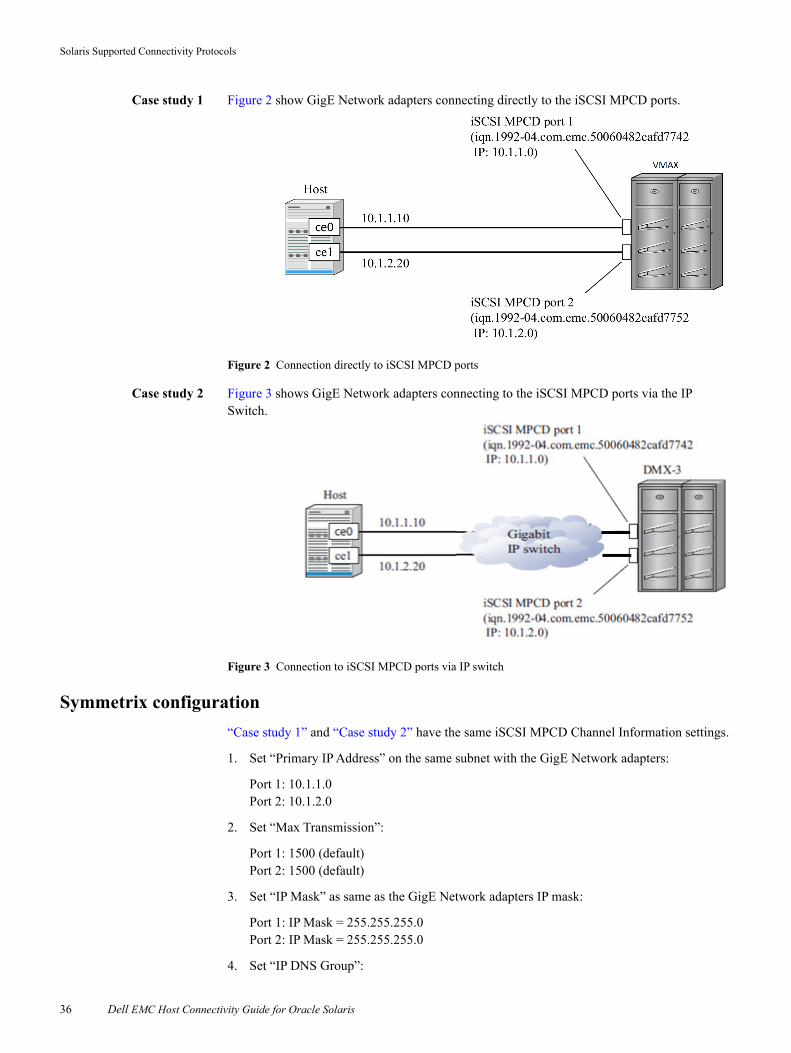
Case study 1 Figure 2 show GigE Network adapters connecting directly to the iSCSI MPCD ports.
Figure 2 Connection directly to iSCSI MPCD ports
Case study 2 Figure 3 shows GigE Network adapters connecting to the iSCSI MPCD ports via the IP Switch.
Figure 3 Connection to iSCSI MPCD ports via IP switch
Symmetrix configuration
“Case study 1” and “Case study 2” have the same iSCSI MPCD Channel Information settings.
1. Set “Primary IP Address” on the same subnet with the GigE Network adapters:
Port 1: 10.1.1.0Port 2: 10.1.2.0
2. Set “Max Transmission”:
Port 1: 1500 (default)Port 2: 1500 (default)
3. Set “IP Mask” as same as the GigE Network adapters IP mask:
Port 1: IP Mask = 255.255.255.0Port 2: IP Mask = 255.255.255.0
4. Set “IP DNS Group”:
36 Dell EMC Host Connectivity Guide for Oracle Solaris

Solaris Supported Connectivity Protocols
Port 1: NONE (default)Port 2: NONE (default)
5. Set “SNMP”:
Port 1: YES (default)Port 2: YES (default)
6. Set “Default Gateway”:
Port 1: 0.0.0.0Port 2: 0.0.0.0
7. Set “ISNS IP Address”:
Port 1: 0.0.0.0Port 2: 0.0.0.0
Solaris 10 host configuration
“Case study 1” and “Case study 2” have the same host settings.
1. Enable network interface for each GigE Network adapter:
# ifconfig ce0 plumb# ifconfig ce1 plumb
2. Set IP for each interface:
# ifconfig ce0 10.1.1.10 netmask 255.255.255.0 up# ifconfig ce1 10.1.2.20 netmask 255.255.255.0 up
3. Add netmask value for the interfaces to the file /etc/inet/netmasks:
10.1.1.0 255.255.255.010.1.2.0 255.255.255.0
4. Add IP address of each interface to the file /etc/hosts:
10.1.1.10 iSCSI010.1.2.20 iSCSI1
5. Create host network file for each interface port:
/etc/hostname.ce0 contains iSCSI0/etc/hostname.ce1 contains iSCSI1
6. You can use the static discovery method or SendTargets device discovery method:
• Configure the static target discovery method:
# iscsiadm add static-config iqn.1992-04.com.emc.50060482cafd7742,10.1.1.0:3260
# iscsiadm add static-config iqn.1992-04.com.emc.50060482cafd7752,10.1.2.0:3260
• Configure the SendTargets device discovery method:
# iscsiadm add discovery-address 10.1.1.0:3260
# iscsiadm add discovery-address 10.1.2.0:3260
7. Enable the iSCSI target discovery method
Solaris connection over iSCSI 37

Solaris Supported Connectivity Protocols
• If you have configured the static discovery method, enable the static target discovery:
# iscsiadm modify discovery –s enable
• If you have configured the SendTargets discovery method, enable the SendTargets discovery:
# iscsiadm modify discovery –t enable
IMPORTANT!You can only enable one discovery method at a time. If both SendTarget and Static discovery methods are enabled at the same time that may cause the host to PANIC.
8. Reboot the host with reconfigure for the changes to take effect:
# reboot -- -r
9. If the host isn’t detected to any iSCSI devices, use the following command to create iSCSI device nodes:
# devfsadm –i iscsi
Solaris 11 host configuration
“Case study 1” and “Case study 2” have the same host settings.
1. Use the dladm show-link command to find out the virtual interface name that asociated to ce0 and ce1 (net2 and net3, in this case).
2. Configure IP for the virtual interface net2 and net3:
# svcadm disable network/physical:nwam# svcadm enable network/physical:default# ipadm create-ip net2# ipadm create-addr -T static -a 10.1.1.10/24 net2/v4static# ipadm create-ip net3# ipadm create-addr -T static -a 10.1.2.20/24 net3/v4static# ipadm show-addr
3. Reboot the host then issue the ifconfig -a command to verify that the IP on both net2 and net3 are up and persistent.
4. You can use the static discovery method or SendTargets device discovery method:
• Configure the static target discovery method:
# iscsiadm add static-config iqn.1992-04.com.emc.50060482cafd7742,10.1.1.0:3260
# iscsiadm add static-config iqn.1992-04.com.emc.50060482cafd7752,10.1.2.0:3260
• Configure the SendTargets device discovery method:
# iscsiadm add discovery-address 10.1.1.0:3260
# iscsiadm add discovery-address 10.1.2.0:3260
5. Enable the iSCSI target discovery method
38 Dell EMC Host Connectivity Guide for Oracle Solaris

Solaris Supported Connectivity Protocols
• If you have configured the static discovery method, enable the static target discovery:
# iscsiadm modify discovery –s enable
• If you have configured the SendTargets discovery method, enable the SendTargets discovery:
# iscsiadm modify discovery –t enable
IMPORTANT!You can only enable one discovery method at a time. If both SendTarget and Static discovery methods are enabled at the same time that may cause the host to PANIC.
6. Reboot the host with reconfigure for the changes to take effect:
# reboot -- -r
7. If the host isn’t detected to any iSCSI devices, use the following command to create iSCSI device nodes:
# devfsadm –i iscsi
Solaris connection over iSCSI 39
Solaris Supported Connectivity Protocols
Solaris Connection over FCoEI/O consolidation has been long sought by the IT industry to unify the multiple transport protocols in the data center. This section provides a basic introduction to Fibre Channel over Ethernet (FCoE), which is a new approach to I/O consolidation that has been defined in the FC-BB-5 T11 work group.
Much of the information in this section was derived from the following sources, which also provide more details on FCoE, including encapsulation, frame format, address mapping, lossless Ethernet, and sample topologies:
• Fibre Channel Over Ethernet White Paper• Silvano, Gai, Data Center Network and Fibre Channel over Ethernet, Nuova Systems Inc.,
2008I/O consolidation, simply defined, is the ability to carry different types of traffic, having different traffic characteristics and handling requirements, over the same physical media. I/O consolidation’s most difficult challenge is to satisfy the requirements of different traffic classes within a single network. Since Fibre Channel is the dominant storage protocol in the data center, any viable I/O consolidation solution for storage must allow for the FC model to be seamlessly integrated. FCoE meets this requirement in part by encapsulating each Fibre Channel frame inside an Ethernet frame.
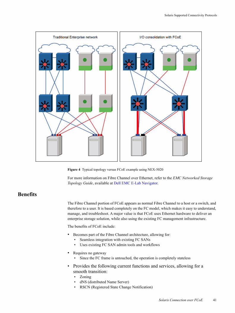
The goal of FCoE is to provide I/O consolidation over Ethernet, allowing Fibre Channel and Ethernet networks to share a single, integrated infrastructure, thereby reducing network complexities in the data center. An example is shown in Figure 4.
FCoE consolidates both SANs and Ethernet traffic onto one Converged Network Adapter (CNA), eliminating the need for using separate host bus adapters (HBAs) and network interface cards (NICs).
40 Dell EMC Host Connectivity Guide for Oracle Solaris
Solaris Supported Connectivity Protocols
Figure 4 Typical topology versus FCoE example using NEX-5020
For more information on Fibre Channel over Ethernet, refer to the EMC Networked Storage Topology Guide, available at Dell EMC E-Lab Navigator.
Benefits
The Fibre Channel portion of FCoE appears as normal Fibre Channel to a host or a switch, and therefore to a user. It is based completely on the FC model, which makes it easy to understand, manage, and troubleshoot. A major value is that FCoE uses Ethernet hardware to deliver an enterprise storage solution, while also using the existing FC management infrastructure.
The benefits of FCoE include:
• Becomes part of the Fibre Channel architecture, allowing for:• Seamless integration with existing FC SANs• Uses existing FC SAN admin tools and workflows
• Requires no gateway• Since the FC frame is untouched, the operation is completely stateless
• Provides the following current functions and services, allowing for a smooth transition:• Zoning• dNS (distributed Name Server)• RSCN (Registered State Change Notification)
Solaris Connection over FCoE 41

Solaris Supported Connectivity Protocols
• FSPF (Fibre Channel Shortest Path First)• Management tools• Storage and server virtualization
Further benefits include:
• Fewer cables, simplifying cable management• Fewer adapters and switch ports, saving in power, equipment, and cooling
costs
Enabling technologies
This section describes just a few of the technologies and protocols required to make I/O consolidation practical in large scale environments:
• “Converged Network Adapter” on page 42
• “Fibre Channel Forwarder” on page 42
• “Priority Flow Control and PAUSE” on page 42
• “Data Center Bridging (lossless Ethernet)” on page 44
• “Data Center Bridging eXchange” on page 44
Converged Network Adapter
A Converged Network Adapter (CNA) is similar to an HBA or a NIC, but instead of handling either FC or IP, the CNA can handle both simultaneously. The CNA presents separate networking and storage system interfaces to the operating system. The interfaces preserve compatibility with existing system software, middleware, and management tools.
From an end-user’s perspective, the FC and Ethernet instances of a CNA appear in the OS just as they would if discrete 10 GbE NIC and FC HBAs were used.
The Ethernet switch to which the CNA connects must contain a Fibre Channel Forwarder (FCF) function of some kind.
Fibre Channel Forwarder
The function of the Fibre Channel Forwarder (FCF) is essentially as follows:
• De-encapsulate FC frames that are coming from the CNA and going to the SAN.
• Encapsulate FC frames that are coming from the SAN and going to the CNA.
Examples of Ethernet switches that provide the FCF functionality are the NEX-5020, NEX-5010, and the EMC Connectrix® MP-8000B.
Priority Flow Control and PAUSE
Priority Flow Control (PFC) (802.1Qbb) enables PAUSE-like (802.3x) functionality on a per-Ethernet priority basis. PFC allows for lossless Ethernet connections to be created for a given priority within an otherwise lossy Ethernet network.
42 Dell EMC Host Connectivity Guide for Oracle Solaris

Solaris Supported Connectivity Protocols
As shown in Figure 5, priority 3 is being paused because the receive buffer hit a threshold. This is done by the receiver transmitting a PAUSE-ON frame. The PAUSE-ON frame contains the priority to be paused, as well as the number of quantas (512-bit increments) for the pause to remain in effect.
Figure 5 PFC and PAUSE example
Once the amount of data in the buffer dips below a certain threshold, either a PAUSE-OFF frame can be transmitted, or the number of quantas will expire and data will start to flow from the Transmit Queue to the Receive buffer.
As with any method of flow control, PFC does have limitations, the most significant of which is any link using it is limited to a maximum distance of 50 m. The reason for the 50 m limitation is due to the amount of buffering available on both of the CNA and FCF. In order for PFC to work properly, the receive buffer has to know the proper time to transmit a PAUSE ON. This requires the receive buffer to not only know how much data it contains, but to also predict the following:
• How much data is actually on the link
• How much additional data can be transmitted before a PAUSE ON frame from the receive buffer would actually reach the transmit queue and be pro-cessed
In order to calculate how much additional data could potentially be received, both the length of the link and the speed at which the link is operating must be known.
Rather than force every user to manually input the length of the link, a maximum distance of 50 m was chosen by at least one hardware manufacturer. Due to interoperability concerns that could arise from mismatched length assumptions, the length has been limited to 50 m for CNA to FCF connections with Gen 1 CNAs.
Gen 2 CNAs can support the maximum distance supported by the physical media in use for the link.
Solaris Connection over FCoE 43
Solaris Supported Connectivity Protocols
Data Center Bridging (lossless Ethernet)
Lossless Ethernet is used to indicate an Ethernet switch implementation that has certain characteristics, the most important being that they do not drop frames under congestion, or are lossless. A lossless network is very important to block I/O operations because unlike TCP/IP, the loss of a single frame typically requires the entire exchange to be aborted and re-driven by the upper-level protocol (ULP), instead of just re-sending a particular chunk of data.
Like the FC-BB-5 standard, Data Center Bridging (DCB) is still a work in progress, but includes:
• Priority-based Flow Control (PFC) — IEEE 802.1Qbb provides a link level flow control mechanism that can be controlled independently for each Class of Service (CoS), as defined by 802.1p. The goal of this mechanism is to ensure zero loss under congestion in DCB networks.
• Enhanced Transmission Selection (ETS) — EEE 802.1Qaz provides a com-mon management framework for assignment of bandwidth to 802.1p CoS-based traffic classes.
• Congestion Notification — IEEE 802.1Qau provides end-to-end congestion management for protocols that are capable of transmission rate limiting to avoid frame loss. It is expected to benefit protocols such as TCP that do have native congestion management, as it reacts to congestion in a more timely manner.
• Data Center Bridging Exchange Protocol (DCBX) — A discovery and capability exchange protocol used for conveying capabilities and configura-tion of the above features between neighbors to ensure consistent configura-tion across the network. This protocol is expected to leverage functionality provided by IEEE 802.1AB (LLDP).
Refer to the Data center bridging Wikipedia article for more information about Data Center Bridging.
Although lossless Ethernet may have wider applications in the future, such as ISCSI. At this time, due to limited test exposure, EMC does not recommend simultaneous use of both FCoE and lossless iSCSI. Traditional iSCSI is fully supported in an FCoE environment, but not lossless iSCSI. As a result, only FCoE traffic will be lossless. TCP and UDP traffic will continue to be lossy on this infrastructure. Both CEE 802.1au and FC-BB-5 are targeted for ratification in 2009.
Data Center Bridging eXchange
The Data Center Bridging Capability eXchange Protocol (DCBCXP), also known as DCBX, is a protocol that extends the Link Layer Discovery Protocol (LLDP) defined in IEEE802.1AB. For FCoE environments, DCBX allows the FCF to provide Link Layer configuration information to the CNA and allows both the CNA and FCF to exchange status.
In order for a CNA to successfully log in to the FCF, the DCBX protocol must be used. If for some reason DCBX was not being used by the CNA, or the CNA was not capable of accepting configuration information pushed to it from the FCF, the link would fail to initialize properly and the FC portion of the CNA would be unable to perform FLOGI. This typically will not be of any concern to users since DCBX is properly configured by default on CNAs and the FCFs.
44 Dell EMC Host Connectivity Guide for Oracle Solaris

Solaris Supported Connectivity Protocols
DCBX frames DCBX frames contain an LLDP PDU (Protocol Data Unit), which in turn consists of many Type Length Value (TLV) entries. Each TLV contains information for one configuration or status parameter. An example of the information contained with one of the TLVs is the Priority Flow Control Sub-TLV which allows for the exchange of Priority Flow Control (PFC) information. The exchange of this information allows for lossless ethernet for Ethernet frames with an FCoE Ether type.
The protocol starts when a physical connection has been established between the CNA and FCF. Both the CNA and FCF start to initialize DCBX by entering a state known as fast initial LLDP retransmission. While in this state, each will transmit one DCBX Ethernet frame (ethertype 0x88CC) per second for five seconds. The purposes of these retransmissions are to allow the link to initialize faster than would otherwise be possible. Once the initial retransmissions have been performed, each side of the link periodically transmits status DCBX frames, either after a configurable time period or immediately after a change in the status of the link. When a DCBX frame is transmitted due to a status change, the sequence number is incremented by one.
Solaris Connection over FCoE 45
Solaris Supported Connectivity Protocols
Configuring the Solaris host To configure the Solaris host, refer to the following documentation:
• Emulex Drivers for Solaris Release Notes• Sun Storage 10 GBE FCoE ExpressModule Converged Network Adapter for
QLogic CNA or Oracle branded QLogic CNA, available on the Oracle Soft-ware Downloads page.
46 Dell EMC Host Connectivity Guide for Oracle Solaris

CHAPTER 3
This chapter provides basic information about using Solaris operating system virtualization technology.
• Solaris Zones 48• Oracle VM Server for SPARC 49
Solaris Virtualization
Solaris Virtualization 47

Solaris Virtualization
Solaris ZonesSolaris Zones, previously known as Container, is an implementation of the Solaris 10 and Solaris 11 operating systems virtualization technology. It is the combination of system resource control and Solaris zones software partitioning technology. Solaris Zones allow many private execution environments to be created within a single instance of the Solaris OS. Each environment has its own identity, separate from the underlying hardware.
There is always one zone defined, the global zone. The zones hosted by a global zone are referred to as non-global zones.
The global zone runs system-wide processes and is used for non-global zone administrative control.
A non-global zone has its own node name, virtual network interface, and storage assigned to it. The non-global zone allows application components to be isolated from one another, even though they share a single instance of the Solaris Operating System.
To set up containers and zones in the Solaris host, refer to System Administration Guide: Solaris Containers-Resource Management and Solaris Zones document, available from the Oracle Help Center page.
The PowerPath pseudo devices (emcpower) can be exported to non-global zones. Instructions on how to export emcpower devices to non-global zones is provided in the PowerPath for Solaris Installation and Administration Guide on Dell EMC Online Support.
IMPORTANT!Dell EMC software applications (including Solution Enabler, PowerPath, Naviagent, etc.) are not supported for installation and use in the non-global zone.
48 Dell EMC Host Connectivity Guide for Oracle Solaris

Solaris Virtualization
Oracle VM Server for SPARC
Note: Oracle VM Server for SPARC (OVM for SPARC) was formerly known as Sun Logical Domains (LDoms).
Oracle VM Server partitioning technology allows the user to allocate a system’s various resources (i.e., CPUs, memory, and devices) into logical groupings and create multiple logical partitions. Each logical partition will be able to run a full instance of Solaris OS, resource, and identity within a single computer system.
Oracle VM Server for SPARC can create three local domains, as follows:
• Control domainDomain in which the Oracle VM Server for SPARC runs, allowing the user to create and manage other logical domains and virtualize its resources for other domains.
• Guest domainDomain that is managed by the control domain and uses services (virtual network, virtual console, and virtual disks) from the control domain.
• I/O domainDomain which has direct access to physical I/O devices.
Boot from SAN (BFS) for Oracle VM Server for SPARC is supported on DELL EMC VMAX/PowerMax, VNX/Unity, XtremIO and VPLEX Provisioned devices.
Oracle VM Server for SPARC only runs on SPARC Enterprise T-series, M5-series, and M10-series systems. Refer to the Dell EMC Support Matrix for specific Oracle server models that support Oracle VM Server for SPARC.
OVM for SPARC is integrated with Solaris 11.x. For Solaris 10, you can download Oracle VM Server for SPARC from Oracle the Oracle Support. Refer also to the Oracle Help Center for the Oracle VM Server for SPARC Release Notes that contain system firmware and Solaris patches requirements.
Oracle VM Server for SPARC 49

Solaris Virtualization
Refer to the Oracle VM Server for SPARC Administration Guide on the Oracle Technology Network Documentation page to install the software, download system firmware, set up services and logical domains, and learn about many other features of Oracle VM Server for SPARC technology.
IMPORTANT!All Dell EMC software applications, (such as PowerPath, Solutions Enabler, Naviagent, and so on.), only support on the domain that has direct access to the Dell EMC storage array, such as control domain and I/O domain.
Dell EMC supports Oracle VM Server for SPARC live migration between hosts in the environments of VMAX/PowerMax, VNX/Unity, XtremIO, and VPLEX (Local and Metro configurations only).
50 Dell EMC Host Connectivity Guide for Oracle Solaris
CHAPTER 4
This chapter discusses the Dell EMC Storage/Solaris Cluster environment. Fundamental concepts and procedures related to Solaris Cluster planning, setup, and administration are provided.
• Solaris Cluster overview 52
• Hardware components 53
• Software components for cluster servers 54
• Solaris Cluster configuration examples 55
• Key Solaris Cluster concepts 59
• Important Solaris Cluster utilities 62
• Configuring VMAX/PowerMax with Solaris Cluster 65• Configuring VNX/Unity series with Solaris Cluster 66• Examples 67
Solaris Cluster
Solaris Cluster 51

Solaris Cluster
Solaris Cluster overviewThis section introduces Solaris Cluster and briefly describes its important features and how they relate to Dell EMC storage.
What is Solaris Cluster?
Solaris Cluster is a highly available and scalable cluster software framework that is tightly integrated with the Solaris Operating Environment. Solaris Cluster is part of the stack that includes the Solaris Operating Environment, Solaris Cluster, SPARC/x86 hardware and networking components. Refer to the Dell EMC Support Matrix for EMC’s latest support for Solaris Cluster.
Solaris Cluster enables the implementation of applications in either a failover or scalable topology or both. A failover configuration is one in which a set of resources and applications are automatically relocated to another server in the event that the primary node fails. For failover services, applications run on only a single server at any one time. In a scalable configuration, a set of resources/applications are spread across cluster servers and run concurrently on them. Service requests come into the cluster through a global network interface and are distributed to the cluster servers based one of several predefined algorithms. Solaris Cluster can also be configured to run Oracle Parallel Server (OPS) or Real Application Cluster (RAC).
For more information about Solaris Clusters, refer to documentation on the Oracle Help Center Operating Systems Documentation page.
52 Dell EMC Host Connectivity Guide for Oracle Solaris

Solaris Cluster
Hardware componentsThis section provides information on the hardware components.
Cluster nodes
A cluster node is a server that is running Solaris, Solaris Cluster framework, and Solaris Cluster Data Service software. Up to six nodes are supported in a High Availability environment. Solaris Cluster can be run on most Oracle server families. Cluster nodes are connected to Symmetrix disks using both Fibre channel and SCSI interfaces. Refer to the Dell EMC Support Matrix for all relevant host bus adapters, drivers, and switch versions. Nodes that are not physically attached to the storage, but participating in cluster membership, can gain access to storage through the cluster file system.
Cluster members communicate with each other through a mechanism called the Cluster Membership Monitor (CMM) over a set of physically independent networks called the cluster interconnect. The cluster interconnect is discussed later in this chapter.
In general, nodes in the cluster should have similar physical resources such as processors, memory, and I/O capability to be able to sufficiently run the applications and resources that might failover to them. Additional server capacity might be required in an Active-Active topology. In such configurations, all servers are primary for one set of resources and are secondary if another server in the cluster failed. In this case, the server might need additional system resources in order to run both sets of applications.
Storage
For a full list of Dell EMC storage arrays that are supported with Solaris Cluster, refer to the Oracle Solaris Cluster Storage Partner Program page.
Refer to the Dell EMC Support Matrix for specific configurations, code revisions, and other considerations.
Cluster interconnect
The cluster interconnect is a set of private networks that are used to carry membership and data service communications between the nodes participating in the cluster. Redundant private networks are used to avoid a single point of failure in the event that one network component should fail. Up to six networks can be configured, and Solaris Cluster will exploit the additional bandwidth when available. Some cluster topologies, such as Real Application Cluster, use the cluster interconnect extensively. For these configurations, high-speed interconnect technologies should be deployed. The cluster interconnect consists of Network Interface Cards (NICs), junctions (switches/hubs), and cables.
Hardware components 53

Solaris Cluster
Software components for cluster serversThe following software packages are generally installed on cluster servers:
• Solaris Operating System
• Solaris Cluster framework software
• Data service applications• Volume Manager (Solaris Volume Manager or zpool on SC4.4)• Multipathing software—Dell EMC PowerPath or Solaris StorEdge Traffic Manager (a/k/a
MPxIO)
Supported software versions for Solaris Cluster
Refer to the Dell EMC Support Matrix for the latest information regarding supported software versions. Refer also to the Oracle My Oracle Support page for the latest Solaris and Solaris Cluster patch levels
54 Dell EMC Host Connectivity Guide for Oracle Solaris

Solaris Cluster
Solaris Cluster configuration examplesThe diagrams on the following pages show several possible configurations for EMC storage systems in a Solaris Cluster environment. Refer to the Solaris Cluster Concepts manual for additional information.
Typical configurations will include two to six (6) nodes depending on the data services in use. Some or all of the nodes may be physically connected to the storage system. The current guidelines are as follows:
• Up to six (6) nodes in an HA configuration (non-OPS/RAC) can be config-ured. Any number of these nodes can be physically connected to the stor-age. While some nodes may not be physically connected to the storage, they have access to storage through the global namespace and cluster file system features in Solaris Cluster. Refer to the Solaris Cluster Concepts Guide and the Solaris Cluster Systems Administration Guide for more information on this functionality.
• Up to four nodes are possible for OPS/RAC in Solaris Cluster. All nodes are physically connected to the Dell EMC storage system.
Solaris Cluster configuration examples 55

Solaris Cluster
Figure 6 shows a four-node fully attached configuration. PowerPath is deployed for this configuration with Symmetrix RAID protection.
Figure 6 Four-node fully attached configuration
56 Dell EMC Host Connectivity Guide for Oracle Solaris

Solaris Cluster
Figure 7 shows a two-node, host-based mirrored configuration. PowerPath is not deployed in this configuration.
Figure 7 Two-node host-based mirrored configuration
Figure 8 and Figure 9 show possible configurations for an VNX/Unity series storage system in a Solaris Cluster environment. Refer to the Solaris Cluster Concepts Guide for additional information.
Figure 8 Typical two-node fabric topology
Solaris Cluster configuration examples 57
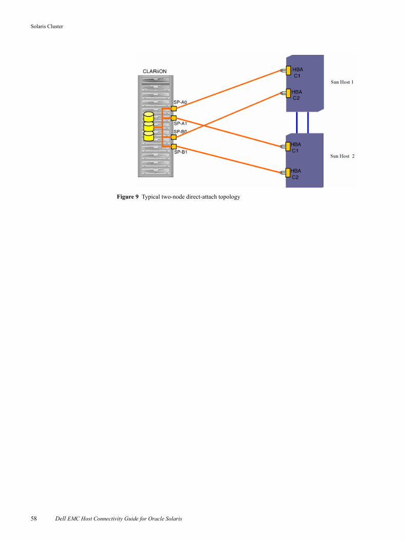
Solaris Cluster
Figure 9 Typical two-node direct-attach topology
58 Dell EMC Host Connectivity Guide for Oracle Solaris

Solaris Cluster
Key Solaris Cluster conceptsThis section provides information on key Solaris Cluster concepts.
Cluster Membership Monitor (CMM)
The Cluster Membership Monitor (CMM) is a set of agents that use the private interconnects to communicate with the nodes that comprise a Solaris Cluster. The CMM performs the following functions:
• Monitors changes in cluster membership when nodes join or leave the cluster• Ensures that a faulty node leaves the cluster• Ensures that a faulty node stays out of the cluster until it is repaired• Protects the cluster from partitioning itself into multiple clusters (split-brain, amnesia)• Verifies full connectivity to all nodes in the cluster
Split-brain is a condition where, in the event that all communication is lost between cluster members, the cluster partitions into each node (or a subset of nodes) and believes it is the only cluster node. In this condition, uncoordinated access to shared storage could result in severe data corruption.
Amnesia is a condition where a node starts with stale cluster configuration data. If a node fails and the cluster is reconfigured on the remaining nodes, then the configuration would be stale on the node that failed. If the failed node then attempts to join the cluster, it must be resynchronized with the current cluster configuration data.
Cluster Configuration Repository (CCR)
The Cluster Configuration Repository (CCR) is a cluster-wide database that stores cluster configuration and state information. Each node in the cluster maintains a copy of the CCR. The Solaris Cluster framework maintains the integrity of the CCR by using a two-phase commit protocol where any update to the cluster configuration from one node must successfully complete on all nodes of the cluster.
Global devices
Solaris Cluster uses a concept called global devices to present a cluster-common device view to all nodes in the cluster regardless of where specific devices are physically attached. The cluster automatically detects storage devices on system boot up and assigns unique IDs to each disk device. Devices are assigned global names, and are by default integrated into the cluster environment. This naming scheme allows for a common name to be used by all nodes in the cluster even the actual hardware path to the shared storage devices could vary from one node to the next. Solaris Cluster essentially abstracts data location from data services. Data does not need to be attached to the server that hosts the services. This global namespace is held in the /dev/global directory on each node.
Key Solaris Cluster concepts 59

Solaris Cluster
Device ID (DID)
To manage the global devices Solaris Cluster uses a pseudo driver called the Device ID (DID). This driver searches for devices attached to the cluster node and automatically builds a list of unique disk devices and assigns a unique major and minor number that’s consistent across the cluster. Device access is then performed using the unique device ID that was assigned by the DID instead of the traditional Solaris CxTxDx device ID.
An example of a device name using the DID naming scheme is:
/dev/did/dsk/d10s2
Global namespace
Global devices are enabled through a construct called the global namespace. The global namespace is implemented using a /global/.devices/node@x structure, where x is a node number within the cluster. This number can be 1 – 6, depending on the number of nodes making up the cluster. The global namespace includes the /dev/global directory hierarchy as well as the SVM volume manager namespaces. All disk devices represented in /dev/global and all SVM metadevices are symbolically linked to a /global/.devices/node@x/dev pseudo entry. Both the global namespace and standard volume manager namespace are available from any node in the cluster.
Table 1 lists examples of local and global namespace mappings.
Cluster file systems
The cluster file system feature of Solaris Cluster is a proxy between the operating system kernel and the underlying file system. It allows for the access of file systems regardless of physical location within the cluster. Cluster file systems are dependent on global devices and can be accessed by any node in the cluster through a common name whether or not that node is physically connected to the storage device.
Cluster file systems enable the ability of mounting file systems on a node that is not physically attached to the storage system.
Cluster file systems are mounted using the mount -g command. They can also be mounted automatically with the /etc/vfstab file. See the section later in this chapter for an example of automatically mounting cluster file systems.
Solaris Cluster data services
For a full list of available Oracle Solaris Cluster data services, refer to the Oracle Solaris Cluster 4 Compatibility Guide.
Table 1 Global namespace mappings
Object Node path name Global path
Disk /dev/dsk/c1t0d10s2 /global/.devices/node@2/dev/dsk/c1t0d10s2
DID Name /dev/did/dsk/d1s2 /global/.devices/node@2/dev/did/dsk/d1s2
SVM Diskset
/dev/md/test/dsk/d11 /global/.devices/node@2/dev/md/test/dsk/d11
60 Dell EMC Host Connectivity Guide for Oracle Solaris

Solaris Cluster
Resource groups
Resource groups are the logical constructs that Solaris Cluster uses to group resources together so they can be managed as a unit and made highly available. A resource group is migrated from one node to another in the event of a cluster node failover or initiated switchover. Resource groups can contain data services, disk device groups, network interfaces or other resources. Dependencies can be defined for resource groups to assure that the group cannot be brought up unless all of it underlying resources are available.
Quorum and failure fencing
With any cluster it is important to protect the disk resource from the possibility of having uncoordinated cluster members from writing to shared storage devices and possibly corrupting data. Solaris Cluster uses the CCM to protect the cluster from partitioning into multiple clusters in the event that the cluster interconnects fail.
Solaris Cluster uses a quorum vote algorithm where each node is assigned one vote. In order for a cluster to be operational it must have a majority of votes. If the cluster interconnects or node fails, the partition with a majority of votes will remain operational. This model works well with clusters with more than two nodes, such as a two node cluster where the vote majority is two and the partitioned nodes could not achieve a majority of votes. Solaris Cluster solves this by assigning an external vote to a quorum device. The quorum device can be any disk device that is shared between two or more nodes. VMAX/PowerMax, VNX/Unity series, or XtremIO devices are commonly used for this purpose. If VPLEX storage is used, the quorum device must be from the same VPLEX storage. We recommend that an external quorum device be configured regardless of node count. “Setting up a Solaris Cluster quorum device on Dell EMC storage” on page 67 provides an example of configuring a quorum device for VMAX/PowerMax.
Key Solaris Cluster concepts 61
Solaris Cluster
Important Solaris Cluster utilitiesThis section provides information on important Solaris Cluster utilities.
scinstall
The scinstall command performs Solaris Cluster node initialization, installation, and upgrade tasks. It can be run as an interactive utility or by the command line.
The scinstall command installs and initializes a node as a new Solaris Cluster member. It either establishes the first node in a new cluster or adds a node to an already-existing cluster. It can also be used to remove cluster configuration information and uninstall Solaris Cluster software from a cluster node.
The upgrade form (-u) of scinstall, which has several modes and options, upgrades a Solaris Cluster node. Always run this form of the scinstall command from the node being upgraded.
The print release form (-p) of scinstall prints release and package versioning information for the Solaris Cluster software installed on the node from which the command is run.
Without options, the scinstall command attempts to run in interactive mode. Run all forms of the scinstall command other than the print release form (-p) as superuser.
The scinstall command is located in the Tools directory on the Solaris Cluster CD-ROM. If the Solaris Cluster install image is copied to a local disk, cdrom-mnt-pt is the path to the copied Solaris Cluster CD-ROM image. The SUNWscu software package also includes a copy of the scinstall command.
clsetup
At post-install time, the clsetup utility performs initial setup tasks, such as configuring quorum devices and resetting installmode. Always run the clsetup utility just after the cluster is installed and all of the nodes have joined for the first time.
After installmode is disabled, clsetup provides a menu-driven front end to most ongoing cluster administration tasks.
You can run clsetup from any node in the cluster. However, when installing a cluster for the first time, it is important to wait until all nodes have joined the cluster before running scsetup and resetting installmode.
The clsetup interactive utility can be used to configure cluster quorum devices.
scconf
The scconf utility manages the Solaris Cluster software configuration. You can use scconf to add items to the configuration, to change properties of previously configured items, and to remove items from the configuration. The scconf command can be used to configure the cluster quorum device. In each of these three forms of the command, options are processed in the order in which they are typed on the command line. All updates associated with each option must complete successfully before the next option is considered.
The scconf command can only be run from an active cluster node. As long as the node is active in the cluster, it makes no difference which node is used to run the command. The results of running the command are always the same, regardless of the node used.
62 Dell EMC Host Connectivity Guide for Oracle Solaris

Solaris Cluster
The -p option of scconf enables you to print a listing of the current configuration.
scdidadm
The scdidadm utility is used to administer the device identifier (DID) pseudo device driver.
The scdidadm utility performs the following primary operations:
• Creates driver configuration files• Modifies entries in the file• Loads the current configuration into the kernel• Lists the mapping between device entries and did driver instance numbers
The startup script /etc/init.d/bootcluster uses the scdidadm utility to initialize the did driver. You can also use scdidadm to update or query the current device mapping between the devices present and the corresponding device identifiers and did driver instance numbers.
scgdevs
The scgdevs utility manages the global device namespace. The global device namespace is mounted under /global and consists of a set of logical links to physical devices. As /dev/global is visible to each node of the cluster, each physical device is visible across the cluster. This fact means that any disk, tape, or CD-ROM that is added to the global devices namespace can be accessed from any node in the cluster. The scgdevs command allows the administrator to attach new global devices (for example, tape drives, CD-ROM drives, and disk drives) to the global devices namespace without requiring a system reboot.
Run the drvconfig and devlinks commands prior to running scgdevs.
Alternatively, use a reconfiguration reboot to rebuild the global namespace and attach new global devices. Run the scgdevs command from a node that is a current cluster member. If this script is run from a node that is not a cluster member, the script exits with an error code and leaves the system state unchanged.
scstat
The scstat utility displays the current state of Solaris Cluster and its components. Only one instance of the scstat utility needs to run on any machine in the Solaris Cluster configuration.
When run without any options, scstat displays the status for all components of the cluster. This display includes the following information:
• A list of cluster members• The status of each cluster member• The status of resource groups and resources
• The status of every path on the cluster interconnect
• The status of every disk device group• The status of every quorum device• The status of every Internet Protocol Network Multipathing group and public network
adapter
Important Solaris Cluster utilities 63

Solaris Cluster
scswitch
The scswitch utility is used to move resource groups or disk device groups from one node to another. It also evacuates all resource groups and disk device groups from a node by moving ownership elsewhere, brings resource groups or disk device groups offline and online, enables or disables resources, switches resource groups to or from an unmanaged state, or clears error flags on resource groups.
You can run the scswitch utility from any node in a Solaris Cluster configuration. If a device group is offline, you can use scswitch to bring the device group online onto any host in the node list. However, after the device group is online, a switchover to a spare node is not permitted. Only one invocation of scswitch at a time is permitted.
Do not attempt to kill an scswitch operation that is already underway.
scshutdown
The scshutdown utility shuts down an entire cluster in an orderly fashion. Before starting the shutdown, scshutdown sends a warning message and then a final message asking for confirmation. Only run the scshutdown command from one node. The scshutdown performs the following actions when it shuts down a cluster:
• Changes all functioning resource groups on the cluster to an offline state. If any transitions fail, scshutdown does not complete and displays an error message.
• Unmounts all cluster file systems. If any unmounts fail, scshutdown does not complete and displays an error message.
• Shuts down all active device services. If any transition of a device fails, scshutdown does
not complete and displays an error message.
• Runs /usr/sbin/init 0 on all nodes and brings them to the OK> prompt.
For detailed instructions on how to use these Solaris Cluster 3.z utilities refer to the Solaris Cluster Reference Manual.
64 Dell EMC Host Connectivity Guide for Oracle Solaris

Solaris Cluster
Configuring VMAX/PowerMax with Solaris ClusterThis section provides information on configuring VMAX/PowerMax with Solaris Cluster.
VMAX/PowerMax setup for Solaris Cluster
The following settings are required for proper operation VMAX/PowerMax within the Solaris Cluster environment:
Solaris Cluster uses SCSI-3 PGR (persistent group reservation) for storage devices that are accessible through more than two paths. VMAX/PowerMax systems support this functionality using the PER setting on the SymmWin Edit Volumes dialog. This flag must be set for all devices that will be presented to the Solaris Cluster nodes.
Note: The SCL director flag must be OFF. The SC3 director flag is not required for Solaris Cluster.
Follow these steps to set up a VMAX/PowerMax system:
1. Configure the VMAX/PowerMax system for operation in the Oracle Solaris operating system environment. Refer to the Dell EMC Support Matrix for details. Verify that the VMAX/PowerMax system is running an appropriate version of the Enginuity/Hypermax operating environment.
2. Set the C (Common Serial Number) director flag for all FA/SA ports to be seen by the Solaris Cluster nodes. This feature is accessed through the SymmWin Edit Directors screen.
3. Set the PER flag for all volumes that will be presented to the Solaris Cluster nodes. This feature is accessed through the SymmWin Edit Volumes screen. The PER flag must also be set for data volumes and quorum devices. It is not needed for gatekeepers and VCM database volumes.
FA port sharing
Multiple Solaris Clusters can share the same FA ports on a VMAX/PowerMax. In addition, VMAX/PowerMax FA ports can be shared between Solaris Cluster nodes and non-clustered Solaris nodes. The EMC Solutions Enabler Array Controls and Management CLI User Guide contains instructions for enabling this feature.
Configuring VMAX/PowerMax with Solaris Cluster 65
Solaris Cluster
Configuring VNX/Unity series with Solaris ClusterSetup and configuration of VNX/Unity series in the Solaris Cluster environment can be set up in fabric or loop mode depending on requirements. Multipathing software (PowerPath or Solaris MPxIO) is required for HA configurations. You must configure a minimum of two paths to each VNX/Unity series system. Refer to the EMC PowerPath for Solaris Release Notes for details on driver and device configuration.
Solaris Cluster uses SCSI-3 PGR (Persistent Group Reservation) for storage devices that are accessible through more than two paths. This is either from a single node or multiple nodes. Figure 8 shows an example of multiple nodes. EMC VNX/Unity series supports this functionality by deploying PowerPath on all cluster nodes.
Installation guidelines
Verify that the VNX/Unity series storage system is running an appropriate version of firmware. Configure the VNX/Unity series storage system for operation in the Oracle Solaris environment. For example, set the following settings on the VNX/Unity series system:
• systemtype to 3 or Solaris• failovermode to 1/3 or PNR/ALUA• unitserialnumber to Array/LUN
For Solaris 10 or later, use the default setting (unitserialnumber = Array).
Solaris Cluster servers
This section provides guidelines for a new installation. Refer to the Solaris Cluster Installation Guide for additional details.
1. Install Oracle Solaris software with latest patch set from Oracle MOS.
2. Ensure that there is at least 512 MB of available space on the local disk for the /globaldevices partition used for the global device namespace.
3. If using a third-party HBA, refer to the Dell EMC Support Matrix for supported server and HBA combinations. Refer to the Fibre Channel PCI and SBus HBA and Driver for Solaris Installation Guide for details on driver and device configuration.
4. (Optional) Install EMC PowerPath software and any required patches. Refer to the PowerPath for Solaris Installation and Administration Guide for details.
5. On all nodes, install the Solaris Cluster framework software (included on the CD Distribution) and any Solaris Cluster Core Packages patches.
6. Set up Solaris cluster by running scinstall on one of the nodes.
7. After the cluster nodes have rebooted, use the /opt/cluster/bin/clsetup utility to reset the cluster installmode and configure a quorum device if necessary.
8. Install the latest Solaris Cluster Patches from Oracle MOS website.
9. Configure Solaris Volume Manager and install the required patches (if any) on all cluster nodes.
66 Dell EMC Host Connectivity Guide for Oracle Solaris
Solaris Cluster
ExamplesThis section provides examples that may be helpful.
Setting up a Solaris Cluster quorum device on Dell EMC storage
A quorum device can be configured either using the interactive clsetup utility or with the clquorum command line utility. Examples of both procedures are given below.
Using the clquorum command:
# /usr/cluster/bin/clquorum add d12
where:
d12 is the global device number.
A list of available shared devices can be generated by using the cldevice list command.
Or:
# /usr/cluster/bin/clquorum add d12
Using the clsetup interactive utility:
1. Run the clsetup utility:
# /usr/cluster/bin/clsetup
The main menu is displayed.
2. Select option 1 (Quorum) from the main menu.
The Quorum Menu is displayed.
3. Select option 1 from the Quorum Menu Add a quorum device.
4. Follow the interactive instructions, and type in the global device number of the device to be used as the quorum device.
5. Verify that the quorum device has been added and is online by running the following command:
# /usr/cluster/bin/clquorum status
Creating a cluster file system
This procedure assumes that all components of the cluster are installed and configured (Solaris Cluster framework and Solaris Volume Manager).
The following example creates a UFS cluster file system on the Solaris Volume Manager volume /dev/md/oracle/rdsk/d1. An entry for the cluster file system is added to the vfstab file on each node. Then, from one node, the cluster check command is run. After configuration check processing is completed successfully, the cluster file system is mounted from one node and verified on all nodes:
phys-schost# newfs /dev/md/oracle/rdsk/d1…phys-schost# mkdir -p /global/oracle/d1phys-schost# vi /etc/vfstab#device device mount FS fsck mount mount#to mount to fsck point type pass at boot options
Examples 67

Solaris Cluster
#/dev/md/oracle/dsk/d1 /dev/md/oracle/rdsk/d1 /global/oracle/d1 ufs 2 yes global,logging…phys-schost# cluster check -k vfstabphys-schost# mount /global/oracle/d1phys-schost# mount…/global/oracle/d1 on /dev/md/oracle/dsk/d1 read/write/setuid/global/logging/largefileson Sun Oct 3 08:56:16 2005
Configuring the Solaris Cluster Data Service for Network File System (NFS)
Building upon the previous section the set up a Solaris Cluster Cluster File System, the following steps can be used to setup HA-NFS for failover.
1. Install the Solaris Cluster HA for NFS packages using the /usr/cluster/bin/scinstall utility
Run the scinstall utility with no options, and select Add support for new data services to this cluster node. Follow prompts to load the data services packages from the data services CD.
Perform the installations on all cluster nodes that will possibly run the data service.
Verify the installation of the Solaris Cluster HA for NFS c by running the following command:
# pkginfo -l SUNWscnfs
2. Register and configure Solaris Cluster HA for NFS
Verify that all of the cluster nodes are online:
# /usr/cluster/bin/clnode status
Add the failover logical hostname/IP address to the /etc/inet/hosts file on ALL cluster nodes. The logical hostname is the name of the entity that will failover from one cluster node to another. An IP address needs to be associated with the logical host.
Create a Pathprefix directory. This directory is used to maintain administrative and status information for Solaris Cluster HA for NFS. For example make the directory on one node as follows:
# mkdir -p /global/nfs
3. Create a failover resource group that will contain the NFS resources:
# clresourcegroup create -n <node1...> -p PathPrefix=/global/nfs <nfs-rg>
where:
<nfs-rg> = name of the resource group<node1,...> = list of cluster nodes that can run the NFS data serviceFor example:
# clresourcegroup create -n node1,node2,node3 -p PathPrefix=/global/nfs nfs-res-group4. Configure name service mapping in the /etc/nsswitch.conf file on all cluster nodes to
first check the local files before checking NIS or NIS+ for rpc lookups. Setting the hosts entry in /etc/nsswitch does not contact NIS/DNS before attempting to resolve names locally.
68 Dell EMC Host Connectivity Guide for Oracle Solaris
Solaris Cluster
# hosts: cluster files [SUCCESS=return] nis# rpc: files nis
Note: Also ensure that the ipnodes entry is of the following format:ipnodes: files
5. Add the logical hostname resources to the failover resource group:
# scrgadm -a -L -g <nfs-rg> -l <log-host-name>
Or:
# clreslogicalhostname create -g <nfs-rg> -h <log-host-name> <log-hostname-resource>
where:
<nfs-rg> = name of the resource group<log-host-name> = name of the logical hostname<log-hostname-resource> = name of the logical hostname resource
6. Create the administrative subdirectory below the Pathprefix directory created earlier. For example:
# mkdir /global/nfs/SUNW.nfs
In the directory created above, create a dfstab.resource file, and type the share options for the NFS data service.
# cd /global/nfs/SUNW.nfs# vi dfstab.nfs-res
The format of this file is the same as the /etc/dfs/dfstab file, and a typical entry would look like:
# share -F nfs -o ro -d <description> nsf/SUNW.nfs
7. Register the NFS resource type.
For Solaris Cluster HA for NFS, the resource type is SUNW.nfs:
# clresourcetype register SUNW.nfs
8. Create the NFS resource in the failover resource group.
# clresource create -g <nfs-rg> -t SUNW.nfs -p <r-nfs>
where:
<r-nfs> = any unique name for the resource<nfs-rg> = name of the resource groupSUNW.nfs = name of the resource type
9. Enable the resources and switch the resource group into the online state:
# clresource group online -emM <nfs-rg>
Setting up Solaris Cluster data service for RAC
The Solaris Cluster data service for Real Application Cluster (RAC) enables these applications to run on Solaris Cluster nodes and to be managed using Solaris Cluster commands. It does not provide for automatic failover or monitoring. RAC has this functionality already built in.
Examples 69

Solaris Cluster
Unlike other Solaris Cluster data services, it is not registered to the Solaris Cluster framework. This is also the case with the shared disk groups that are used by RAC and Solaris Volume Manager, and are supported with the Cluster feature. The Cluster features enables the ability to create shared disk groups. Shared disk groups are simultaneously imported on multiple cluster nodes. The Cluster feature requires a separate license in addition to the base Veritas Volume Manager license.
RAC also can be used without a volume manager with Solaris Cluster. In this configuration, redundancy is provided by the RAID support on the storage array.
General setup guidelines for configuring Solaris Cluster OPS/RAC data service
Refer to detailed configuration instructions in the Solaris Cluster Data Service for Oracle Real Application Clusters Guide. The following steps assume that the Solaris Cluster framework and RAC and Volume Manager are installed. Refer to the installation guides for those products for specific installation procedures. This examples assume that Veritas Volume Manager is being used.
1. Install the Solaris Cluster Support for RAC packages from the Solaris Cluster Data Services distribution cd.
For Solaris 9:
# cd /cdrom/suncluster_3_1/Sol_9/Packages
On all cluster nodes that will be running the OPS/RAC data service install the packages:
# pkgadd -d . SUNWscucm SUNWscor SUNWudlm SUNWudlmr SUNWcvmr SUNWcvm
Repeat these procedures on the other cluster nodes that will run the data service. Do not reboot the nodes until the Oracle Distributed Lock Manager (UDLM) has been installed and the shared memory settings have been set up in the /etc/system file on all nodes. Verify that licenses for both the Veritas Volume Manager and Veritas Cluster Feature are installed on all nodes.
2. Install the Oracle UDLM
If not already created, a database administrator group and Oracle user account must be created.
On each node, an example entry in to the /etc/group file for the dba group could look like the following:
dba:*:600:root,oracle
One each node, create an entry for the Oracle use ID in the /etc/passwd file. For example:
# useradd -u 600 -g dba -d /oracle-home oracle
The group/Oracle user ID should be the same on all nodes running the RAC data service.
Install the ORCLudlm package on each of the nodes to run the RAC data service.
3. Update the /etc/system file to provide appropriate shared memory resource. These values depend on available resources of the server nodes.
Note: This is an example of the /etc/system file parameter settings only:
70 Dell EMC Host Connectivity Guide for Oracle Solaris

Solaris Cluster
*SHARED MEMORY SETTINGS FOR ORACLE
set shmsys:shminfo_shmmax=4294967295
set semsys:seminfo_semmap=8024
set semsys:seminfo_semmni=8048
set semsys:seminfo_semmns=8048
set semsys:seminfo_semmsl=8048
set semsys:seminfo_semmnu=8048
set semsys:seminfo_semume=2048
set shmsys:shminfo_shmmin=2048
set shmsys:shmminfo_shmmni=2048
set shmsys:shminfo_shmseg=2048
set semsys:seminfo_semvmx=32767
Shut down and reboot all the cluster nodes that will run the RAC data service.
4. Create a shared disk group for used with the Solaris Cluster RAC data service.
The disk devices need to be initialized for use with the volume manager. The following is a example command:
# /etc/vx/bin/vxdisksetup -i c2t0d25
Run this command for each device that will be used by the Veritas Volume Manager. The Veritas vxdiskadm or VMSA utilities can also be used to initialize disk and create disk groups.
Create a shared disk group:
# vxdg -s init <disk-group-name> c2t0d25 c2t0d26 c2t027 ...
Run the following command to list disk groups:
# vxdg list
At this point, a shared disk group is created and can be used to store the database associated with the RAC application.
Examples 71

Solaris Cluster
72 Dell EMC Host Connectivity Guide for Oracle Solaris

CHAPTER 5Invisible Body Tag
This chapter provides information about provisioning from Dell EMC storage to Solaris.
• Configuring MPxIO for DELL EMC storage devices 74• Creating and mounting a file system 75• Volume Manager feature functionality 81
Provisioning from Dell EMC storage to Solaris
Provisioning from Dell EMC storage to Solaris 73

Provisioning from Dell EMC storage to Solaris
Configuring MPxIO for DELL EMC storage devicesMPxIO is a feature of the Oracle SAN application that allows I/Os to fail over from one path to another available path and that automatically resumes on the original path when the original path is repaired.
To enable MPxIO support for DELL EMC storage devices on a SPARC/x86 server running Solaris 10:
• Set to the file /kernel/drv/fp.conf parameter:
mpxio-disable="no";
• Set the following parameters to the file /kernel/drv/scsi_vhci.conf:
load-balance="round-robin";auto-failback="enable";
Table 2 lists the property names, defaults, and possible MPxIO parameter values on Solaris 10.
Note: EMC recommends using the default setting for load balancing, (round-robin).
For Solaris 11, enter the following command:
stmsboot -e [-D fp|iscsi]
Alternatively, you can set the following parameter to the file /etc/driver/drv/fp.conf and then reboot:
mpxio-disable= "no";
Table 2 MPxIO parameter values
Property name Default Possible values
mpxio-disable no yes or no
auto-failback enable enable or disable
load-balance round-robin none or round-robin
74 Dell EMC Host Connectivity Guide for Oracle Solaris

Provisioning from Dell EMC storage to Solaris
Creating and mounting a file systemVolumes created and managed by SVM or VxVM volume manager can be used as raw devices, with the standard UNIX file system (UFS), or with the VxFS journaled file system. Zpool or ZFS is another option in Solaris 10 or 11.
Intent logging
Intent logging records pending changes to the file system structure in an intent log. The intent log is replayed during system failure recovery to complete or abandon changes to the structure that were pending at the time of system failure. The file system can then be mounted without completing a full structural check (fsck). An intent logging system can significantly reduce recovery time following a system failure.
Intent logging can be performed at the file system level or at the volume manager level. Intent logging at the file system level, generally known as a journaling file system (JFS), is usually more effective than volume manager intent logging.
VxFS and VxVM intent logging
The Veritas File System (VxFS) includes a journaling file system that provides intent logging at the file system level. Pending changes to the file system, written to an intent log, are scanned during recovery from a system failure. Changes that were active at the time of failure are completed, and the file system is mounted without requiring a fsck of the entire file system. File system recovery is done in a few seconds; much faster than a standard UFS recovery that requires a complete fsck.
VxVM Dirty Region Logging (DRL) provides intent logging at the volume manager level to reduce the time required to resynchronize mirrored volumes after a system failure. DRL is applied to VxVM mirrored volumes only. Striped or concatenated volumes do not use intent logging, but may rely on VxFS for fast recovery.
SVM intent logging
SVM uses a standard UNIX file system (UFS) that does not provide intent logging at the file system level. However, the Veritas File System (VxFS) can be used in the SVM environment to provide a journaling file system for SVM volumes.
At the volume manger level, SVM uses a method called the UFS logging feature to provide intent logging for all volume types (striped, concatenated, mirrored, and RAID). UFS logging is not a journaling file system. It uses the standard UFS and does intent logging at the volume manager level.
The following paragraphs outline the steps required to add, create and mount a standard UNIX file system or a VxFS journaled file system for volumes and raw devices.
IMPORTANT
You can place the DELL EMC storage devices in the mount table. This requires editing /etc/vfstab. This file is syntax-sensitive, and if not edited properly can prevent the system from booting.
Creating and mounting a file system 75
Provisioning from Dell EMC storage to Solaris
UFS on raw devices
To create standard UNIX file systems under Solaris OS, log in as root and proceed as follows for each new device.
Creating a new filesystem
After you have formatted, partitioned, and labeled each DELL EMC storage device, create a new file system for each DELL EMC storage disk. To do this, use the newfs command in a statement similar to the following:
newfs -v /dev/rdsk/c1t0d0s0
At the Construct new file system? prompt, type y and press Enter.
The actions above created a new file system for the DELL EMC storage disk connected to SCSI controller 1, target ID 0, lun 0, partition 0.
Creating a mountdirectory
After the file systems for each storage device are created, create a mount directory for each device. To do this, type a statement similar to the following for each storage device:
mkdir /fs/c1t0d0s0
where /fs/c1t0d0s0 is the complete path for the new file system directory.
Note: The /fs directory must exist prior to creating the mount directories.
Mounting the file system To mount each file system, type a statement similar to the following:
mount /dev/dsk/c1t0d0s0 /fs/c1t0d0s0
VxFS on raw device
A VxFS journaling file system is created using the mkfs command with arguments provided for block size, log size, device name and size. To create a VxFS file system first determine the size in sectors of the volume. The size of the volume is displayed under the Sector Count field of the prtvtoc output.
After you have formatted, partitioned, and labeled each DELL EMC storage device, create a new file system for each storage disk. To create VxVM journaling file systems under VxFS and Solaris OS, log in as root and proceed as follows for each new device.
Creating a new filesystem
1. To display sector count information, type:
prtvtoc /dev/rdsk/c1t0d0s0
Note: The size of the disk is displayed under the Sector Count field. (Assume 4099000 for this example.)
2. To create the VxFS file system for the volume, type:
mkfs -F vxfs -o bsize=4096,logsize=256 /dev/rdsk/c1t0d0s0 4099000
where: bsize = block size in bytes (1k, 2k, 4k, or 8k - 1k default for file systems < 4 GB, 4k default for file systems > 4 GBlogsize = size of VxFS file system logging in blocks (256 blocks default, 32 to 1024 blocks)4099000 = file system size in sectors (from prtvtoc command)
76 Dell EMC Host Connectivity Guide for Oracle Solaris
Provisioning from Dell EMC storage to Solaris
Creating a mountdirectory
After the file systems for each storage device are created, create a mount directory for each device. To do this, type a statement similar to the following for each storage device:
mkdir /fs/c1t0d0s0
where /fs/c1t0d0s0 is the complete path for the new file system directory.
Mounting the file system To mount each file system, type a statement similar to the following:
mount -F vxfs /dev/dsk/c1t0d0s0 /fs/c1t0d0s0
UFS on SVM device
To create a standard UNIX file system (UFS) under SVM, log in as root and proceed as follows for each new device.
Creating a new filesystem
After you have formatted, partitioned, and labeled each DELL EMC storage device, and created SVM volumes, create a new file system on each volume. To do this, use the newfs command in a statement similar to the following:
newfs -v /dev/md/rdsk/d0
At the Construct new filesystem? prompt, type y and press Enter.
The actions above created a new file system for the storage disk defined as SVM metadevice d0.
Creating a mountdirectory
Once the file systems for each device are created, create a mount directory for each device. To do this, type a statement similar to the following for each device:
mkdir /fs/d0
where /fs/d0 is the complete path for the new file system directory.
Note: You can assume that the /fs directory existed prior to creating the d0 directory.
Mounting the file system
To mount each file system, type a statement similar to the following:
mount /dev/md/dsk/d0 /fs/d0
VxFS on SVM device
A VxFS journaling file system is created using the mkfs command with arguments provided for block size, log size, device name, and size. To create a VxFS file system first determine the size in sectors of the volume. The size of the volume is displayed under the Sector Count field of the prtvtoc output.
To create VxFS journaling file systems under Solstice DiskSuite, log in as root and proceed as follows for each new device.
Creating a new filesystem
1. To display sector count information, type:
prtvtoc /dev/md/rdsk/d0
Creating and mounting a file system 77
Provisioning from Dell EMC storage to Solaris
Note: The size of the disk is displayed under the Sector Count field. (Assume 4099000 for this example.)
2. To create the VxFS file system for the volume, type:
mkfs -F vxfs -o bsize=1024 logsize=512 /dev/md/rdsk/d0 4099000
where: bsize = block size in bytes (1k, 2k, 4k, or 8k - 1k default for file systems < 4 GB, 4k default for file systems > 4 GBlogsize = size of VxFS file system logging in blocks (256 blocks default, 32 to 1024 blocks)4099000 = file system size in sectors (from prtvtoc command)
Create mount directory After the file systems for each device are created, create a mount directory for each device. To do this, type a statement similar to the following for each device:
mkdir /fs/d0
where /fs/d0 is the complete path for the new file system directory.
Mounting the file system To mount each file system, type a statement similar to the following:
mount -F vxfs /dev/md/dsk/d0 /fs/d0
UFS on VxVM devices
To create a standard UNIX file system (UFS) under Veritas Volume Manager, log in as root and proceed as follows for each new device.
Creating a new file system
After you have formatted, partitioned, and labeled each DELL EMC storage device, and created VxVM volumes, create a new file system on each volume. To do this, use the newfs command in a statement similar to the following:
newfs -v /dev/vx/rdsk/dskgrp/vol1
At the Construct new filesystem? prompt, type y and press Enter. These actions created a new file system for the storage disk defined as vol1 in the diskgroup named dskgrp.
Creating a mountdirectory
After the file systems for each device are created, create a mount directory for each device. To do this, type a statement similar to the following for each device:
mkdir /fs/vol1
where /fs/vol1 is the complete path for the new file system directory.
Mounting the file system To mount each file system, type a statement similar to the following:
mount -F vsfs /dev/vx/dsk/dskgrp/vol1 /fs/vol1
78 Dell EMC Host Connectivity Guide for Oracle Solaris

Provisioning from Dell EMC storage to Solaris
VxFS on VxVM devices
A VxFS journaling file system is created using the mkfs command with arguments provided for block size, log size, device name, and size. To create a VxFS file system first determine the size in sectors of the volume. The size of the volume is displayed under the Sector Count field of the prtvtoc output.
To create VxFS journaling file systems under Veritas Volume Manager, log in as root and proceed as follows for each new device.
Creating a new file system
1. To display sector count information, type:
prtvtoc /dev/vx/rdsk/dskgrp/vol1
Note: The size of the disk is displayed under the Sector Count field. (Assume 4099000 for this example.)
2. To create the VxFS file system for the volume, type:
mkfs -F vxfs -o bsize=4096 logsize=512 /dev/vx/rdsk/dskgrp/vol1 4099000
where:
bsize = block size in bytes (1k, 2k, 4k, or 8k - 1k default for file systems < 4 GB, 4k default for file systems > 4 GBlogsize = size of VxFS file system logging in blocks (256 blocks default, 32 to 1024 blocks)4099000 = file system size in sectors (from prtvtoc command)
Creating a mount directory
After the file systems for each device are created, create a mount directory for each device. To do this, type a statement similar to the following for each device:
mkdir /fs/vol1
where /fs/vol1 is the complete path for the new file system directory.
Mounting the file system
To mount each file system, type a statement similar to the following:
mount -F vxfs /dev/vx/dsk/dskgrp/vol1 /fs/vol1
File system expansion
SVM enables you to increase the available storage space of an existing volume by concatenating additional volumes to the metadevice using metattach. A file system can then be expanded to fill all or part of the additional space using the growfs command. The file system can remain mounted, but will be locked (lockfs) during the expansion. For detailed information on expanding a file system under SVM, refer to the SVM Administration guide.
VxVM allows growing of a mounted file system using vxassist commands. The following steps outline the procedure:
1. Log in as root.
2. To determine how large the volume can grow, type:
Creating and mounting a file system 79

Provisioning from Dell EMC storage to Solaris
vxassist maxgrow vol
where vol is the volume name.
The result is similar to the following:
Volume vol can be extended by 12533760 to 16629760 (8120Mb)
3. To determine the size of the current volume, type:
vxprint -vt
The result is similar to the following:
The length unit is in sectors (1 sectors = 512 bytes). Therefore vol is approximately 2 GB.
4. To grow the volume vol to 4 GB, type:
vxassist growto cust-mirvol 4gvxprint -vt
The result is similar to the following:
Disk group: custV NAME USETYPE KSTATE STATE LENGTH READPOL PREFPLEXv vol fsgen ENABLED ACTIVE 4096000 ROUND -
Disk group: custV NAME USETYPE KSTATE STATE LENGTH READPOL PREFPLEXv cust-mirvol fsgen ENABLED ACTIVE 8388608 ROUND -
80 Dell EMC Host Connectivity Guide for Oracle Solaris
Provisioning from Dell EMC storage to Solaris
Volume Manager feature functionalityThis section contains general support rules and guidelines regarding special features and functionality available for FS or volume manager. Always consult the Dell EMC Support Matrix for the latest supported features and functionality available in Solaris.
Thin Reclamation (VxVM/ZFS)
Array-based Thin Reclamation is supported with VMAX/PowerMax, Unity, XtremIO and VPLEX. Thin Reclamation functionality is performed on a per-LUN basis.
Solaris host-based Thin Reclamation requires the following software components:
• Veritas Storage foundation 5.1 SP1 and later with DMP• (Required for Solaris 9 SPARC and Solaris 10 SPARC)
• Veritas Storage foundation 6.0 PR1 and later with DMP• (Required for Solaris 11 SPARC)
• ZFS with MPxIO on Solaris 10 with patch 150401-07 and 11.x (raid0 and raid1)• PowerMax• VMAX3 or VMAX AF with Hypermax OS 5977.250.189 or later• VMAX 40K with Enginuity 5876.82.57 or later• VMAX 20K with Enginuity 5876.82.57 or later• VMAX with Enginuity 5875.135.91 or later• VMAX 10K (Systems with SN xxx987xxxx)with Enginuity 5876.159.102• VMAX 10K (Systems with SN xxx959xxxx)with Enginuity 5876.159.102• VMAXe with Enginuity 5875.198.148e• XtremIO with OE 4.0 or later• VPLEX with GeoSynchrony 6.0 or later ( this is supported in collaboration with back-end
storage. Please refer to latest ESM for more details)• DELL EMC PowerPath is not supported with host-based Thin Reclamation at this time.
Note: Refer to the Dell EMC Support Matrix for the most up-to-date support information.
SmartMove (VxVM)
VxVM SmartMove is supported with Dell EMC VMAX/PowerMax arrays and later. Dell EMC supports SmartMove with minimum VxVM 5.1
Volume Manager feature functionality 81

Provisioning from Dell EMC storage to Solaris
Online Volume Expansion
ZFS with MPxIO as multipathing SW supports Online Volume Expansion. To enable Online Volume Expansion support, set the following criterias for ZFS:
• Set the auto_expand property of ZFS to on• Set the property whole_disk to 1
All DELL EMC storage arrays that support LUN expansion, will support Online Volume Expansion.
82 Dell EMC Host Connectivity Guide for Oracle Solaris

PART 2
Part 2 includes the following chapters:
• Chapter 6, ”Storage Virtual Provisioning”• Chapter 7, ”Solaris and VMAX/PowerMax Connectivity,”• Chapter 8, ”Solaris and VNX/Unity Connectivity,”• Chapter 9, ”Solaris and XtremIO Storage Connectivity”• Chapter 10, ”Solaris and VPLEX connectivity,”
Solaris and Dell EMC Storage


CHAPTER 6Invisible Body Tag
This chapter provides information about storage virtual provisioning and Solaris.
Note: For further information regarding the correct implementation of storage virtual provisioning, refer to the Symmetrix Virtual Provisioning Implementation and Best Practices Technical Note, available on Dell EMC Online Support.
• Virtual Provisioning on Symmetrix 86• Implementation considerations 90• Operating system characteristics 94
Storage Virtual Provisioning
Storage Virtual Provisioning 85
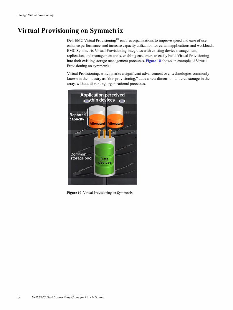
Storage Virtual Provisioning
Virtual Provisioning on SymmetrixDell EMC Virtual Provisioning™ enables organizations to improve speed and ease of use, enhance performance, and increase capacity utilization for certain applications and workloads. EMC Symmetrix Virtual Provisioning integrates with existing device management, replication, and management tools, enabling customers to easily build Virtual Provisioning into their existing storage management processes. Figure 10 shows an example of Virtual Provisioning on symmetrix.
Virtual Provisioning, which marks a significant advancement over technologies commonly known in the industry as “thin provisioning,” adds a new dimension to tiered storage in the array, without disrupting organizational processes.
Figure 10 Virtual Provisioning on Symmetrix
86 Dell EMC Host Connectivity Guide for Oracle Solaris

Storage Virtual Provisioning
Terminology
This section provides common terminology and definitions for DELL EMC storage and thin provisioning.
Symmetrix Basic Symmetrix terms include:
Thin provisioning Basic thin provisioning terms include:
Device A logical unit of storage defined within an array.
Device capacity The storage capacity of a device.
Device extent Specifies a quantum of logically contiguous blocks of storage.
Host accessible device A device that can be made available for host use.
Internal device A device used for a Symmetrix internal function that cannot be made accessible to a host.
Storage pool A collection of internal devices for some specific purpose.
Thin device A host accessible device that has no storage directly associated with it.
Data device An internal device that provides storage capacity to be used by thin devices.
Thin pool A collection of data devices that provide storage capacity for thin devices.
Thin pool capacity The sum of the capacities of the member data devices.
Thin pool allocated capacity A subset of thin pool enabled capacity that has been allocated for the exclusive use of all thin devices bound to that thin pool.
Thin device user pre-allocated capacity
The initial amount of capacity that is allocated when a thin device is bound to a thin pool. This property is under user control.
Bind Refers to the act of associating one or more thin devices with a thin pool.
Pre-provisioning An approach sometimes used to reduce the operational impact of provisioning storage. The approach consists of satisfying provisioning operations with larger devices that are needed initially, so that the future cycles of the storage provisioning process can be deferred or avoided.
Virtual Provisioning on Symmetrix 87

Storage Virtual Provisioning
Thin device
Symmetrix Virtual Provisioning introduces a new type of host-accessible device called a thin device that can be used in many of the same ways that regular host-accessible Symmetrix devices have traditionally been used. Unlike regular Symmetrix devices, thin devices do not need to have physical storage completely allocated at the time the devices are created and presented to a host. The physical storage that is used to supply disk space for a thin device comes from a shared thin storage pool that has been associated with the thin device.
A thin storage pool is comprised of a new type of internal Symmetrix device called a data device that is dedicated to the purpose of providing the actual physical storage used by thin devices. When they are first created, thin devices are not associated with any particular thin pool. An operation referred to as binding must be performed to associate a thin device with a thin pool.
When a write is performed to a portion of the thin device, the Symmetrix allocates a minimum allotment of physical storage from the pool and maps that storage to a region of the thin device, including the area targeted by the write. The storage allocation operations are performed in small units of storage called data device extents. A round-robin mechanism is used to balance the allocation of data device extents across all of the data devices in the pool that have remaining unused capacity.
When a read is performed on a thin device, the data being read is retrieved from the appropriate data device in the storage pool to which the thin device is bound. Reads directed to an area of a thin device that has not been mapped do not trigger allocation operations. The result of reading an unmapped block is that a block in which each byte is equal to zero will be returned. When more storage is required to service existing or future thin devices, data devices can be added to existing thin storage pools. New thin devices can also be created and associated with existing thin pools.
It is possible for a thin device to be presented for host use before all of the reported capacity of the device has been mapped. It is also possible for the sum of the reported capacities of the thin devices using a given pool to exceed the available storage capacity of the pool. Such a thin device configuration is said to be over-subscribed
Over-subscribed thin pool A thin pool whose thin pool capacity is less than the sum of the reported sizes of the thin devices using the pool.
Thin device extent The minimum quantum of storage that must be mapped at a time to a thin device.
Data device extent The minimum quantum of storage that is allocated at a time when dedicating storage from a thin pool for use with a specific thin device.
88 Dell EMC Host Connectivity Guide for Oracle Solaris

Storage Virtual Provisioning
In Figure 11, as host writes to a thin device are serviced by the Symmetrix array, storage is allocated to the thin device from the data devices in the associated storage pool. The storage is allocated from the pool using a round-robin approach that tends to stripe the data devices in the pool. .
Figure 11 Thin device and thin storage pool containing data devices
Virtual Provisioning on Symmetrix 89

Storage Virtual Provisioning
Implementation considerationsWhen implementing virtual provisioning, it is important that realistic utilization objectives are set. Generally, organizations should target no higher than 60 percent to 80 percent capacity utilization per pool. A buffer should be provided for unexpected growth or a “runaway” application that consumes more physical capacity than was originally planned for. There should be sufficient free space in the storage pool equal to the capacity of the largest unallocated thin device.
Organizations also should balance growth against storage acquisition and installation timeframes. We recommend that the storage pool be expanded before the last 20 percent of the storage pool is utilized, to allow for adequate striping across the existing data devices and the newly added data devices in the storage pool.
Thin devices can be deleted once they are unbound from the thin storage pool. When thin devices are unbound, the space consumed by those thin devices on the associated data devices is reclaimed.
Note: Users should first replicate the data elsewhere to ensure it remains available for use.
Data devices can also be disabled and/or removed from a storage pool. Prior to disabling a data device, all allocated tracks must be removed (by unbinding the associated thin devices). This means that all thin devices in a pool must be unbound before any data devices can be disabled.
This section provides the following information:
• “Over-subscribed thin pools” on page 90• “Thin-hostile environments” on page 91• “Pre-provisioning with thin devices in a thin hostile environment” on page 91• “Host boot/root/swap/dump devices positioned on Symmetrix virtual provisioning (tdev)
devices” on page 92• “Cluster configurations” on page 93
Over-subscribed thin pools
The amount of storage mapped to a thin device can be less than the reported size of the device. The sum of the reported sizes of the thin devices using a given thin pool can also exceed the total capacity of the data devices comprising the thin pool. In this case the thin pool is said to be over-subscribed. Over-subscribing allows the organization to present larger-than-needed devices to hosts and applications without having to purchase enough physical disks to fully allocate all of the space represented by the thin devices.
The capacity utilization of over-subscribed pools must be monitored to determine when space must be added to the thin pool to avoid out-of-space conditions.
Not all operating systems, filesystems, logical volume managers, multipathing software, and application environments will be appropriate for use with over-subscribed thin pools. If the application, or any part of the software stack underlying the application, has a tendency to produce dense patterns of writes to all available storage, thin devices will tend to become fully allocated quickly. If thin devices belonging to an over-subscribed pool are used in this type of environment, out-of-space and undesired conditions can be encountered before an administrator can add storage capacity to the thin data pool. Such environments are called thin-hostile.
90 Dell EMC Host Connectivity Guide for Oracle Solaris

Storage Virtual Provisioning
Thin-hostile environments
There are a variety of factors that can contribute to making a given application environment thin-hostile, including:
• One step, or a combination of steps, involved in simply preparing storage for use by the application may force all of the storage that is being presented to become fully allocated.
• If the storage space management policies of the application and underlying software com-ponents do not tend to reuse storage that was previously used and released, the speed in which underlying thin devices become fully allocated will increase.
• Whether any data copy operations (including disk balancing operations and de-fragmenta-tion operations) are carried out as part of the administration of the environment.
• If there are administrative operations, such as bad block detection operations or file system check commands, that perform dense patterns of writes on all reported storage.
• If an over-subscribed thin device configuration is used with a thin-hostile application envi-ronment, the likely result is that the capacity of the thin pool will become exhausted before the storage administrator can add capacity unless measures are taken at the host level to restrict the amount of capacity that is actually placed in control of the application.
Pre-provisioning with thin devices in a thin hostile environment
In some cases, many of the benefits of pre-provisioning with thin devices can be exploited in a thin-hostile environment. This requires that the host administrator cooperate with the storage administrator by enforcing restrictions on how much storage is placed under the control of the thin-hostile application.
For example:
• The storage administrator pre-provisions larger than initially needed thin devices to the hosts, but only configures the thin pools with the storage needed initially. The various steps required to create, map, and mask the devices and make the target host operating systems recognize the devices are performed.
• The storage administrator pre-provisions larger than initially needed thin devices to the hosts, but only configures the thin pools with the storage needed initially. The various steps required to create, map, and mask the devices and make the target host operating systems recognize the devices are performed.
• The host administrator uses a host logical volume manager to carve out portions of the devices into logical volumes to be used by the thin-hostile applications.
• The host administrator can fully preallocate the thin devices underlying these logical vol-umes before handing them off to the thin-hostile application so that any storage capacity shortfall will be discovered as quickly as possible, and discovery is not made by way of a failed host write.
• When more storage needs to be made available to the application, the host administrator extends the logical volumes out of the thin devices that have already been presented. Many databases can absorb an additional disk partition non-disruptively, as can most file systems and logical volume managers.
• Again, the host administrator can fully allocate the thin devices underlying these volumes before assigning them to the thin-hostile application.
In this example it is still necessary for the storage administrator to closely monitor the over-subscribed pools. This procedure will not work if the host administrators do not observe restrictions on how much of the storage presented is actually assigned to the application.
Implementation considerations 91
Storage Virtual Provisioning
Host boot/root/swap/dump devices positioned on Symmetrix virtual provisioning (tdev) devices
A boot /root /swap /dump device positioned on Symmetrix virtual provisioning (thin) devices is supported with Enginuity 5773 and later. However, some specific processes involving boot /root/swap/dump devices positioned on thin devices should not have exposure to encountering the out-of-space condition. Host-based processes such as kernel rebuilds, swap, dump, save crash, and Volume Manager configuration operations can all be affected by the thin provisioning out-of-space condition. This exposure is not specific to a Dell EMC implementation of thin provisioning. Dell EMC strongly recommends that you avoid encountering the out-of-space condition involving boot / root /swap/dump devices positioned on Symmetrix VP (thin) devices by using the following recommendations:
• Virtual provisioning devices utilized for boot /root/dump/swap volumes must be fully allocated1 or the virtual provisioning devices must not be oversubscribed2. If a customer uses an over-subscribed thin pool, they should understand that they need to take the necessary precautions to ensure that they do not encounter the out-of-space condition.
1. A fully allocated DELL EMC storage virtual provisioning (thin) device has 100% of the advertised space mapped to blocks in the data pool that it is bound to. This can be achieved by use of the DELL EMC storage virtual provisioning pre-allocation mechanism or host-based utilities that enforce pre-allocation of the space (such as, host device format).
2. An over-subscribed Symmetrix virtual provisioning (thin) device is a thin device, bound to a data pool, that does not have sufficient capacity to allocate for the advertised capacity of all the thin devices bound to that pool.
92 Dell EMC Host Connectivity Guide for Oracle Solaris
Storage Virtual Provisioning
? We do not recommend implementing space reclamation, available with Enginuity 5874 and later, with pre-allocated or over-subscribed Symmetrix virtual provisioning (thin) devices that are utilized for host boot/root/swap/dump volumes. Although not recommended, Space reclamation is supported on the listed types of volumes
If a customer uses space reclamation on this thin device, they need to be aware that this freed space may ultimately be claimed by other thin devices in the same pool and may not be available to that particular thin device in the future.
Cluster configurations
When using high availability in a cluster configuration, no single point of failure exists within the cluster configuration and that one single point of failure will not result in data unavailability, data loss, or any significant application becoming unavailable within the cluster. Virtual provisioning devices (thin devices) are supported with cluster configurations; however, over-subscription of virtual devices can constitute a single point of failure if an out-of-space condition is encountered. To avoid potential single points of failure, take appropriate steps to avoid under-provisioned virtual devices implemented within high availability cluster configurations.
Implementation considerations 93
Storage Virtual Provisioning
Operating system characteristics Most host applications will behave in a similar manner in comparison to the normal devices when writing to thin devices. This same behavior can also be observed as long as the thin device written capacity is less than thin device subscribed capacity. However, issues can arise when the application writes beyond the provisioned boundaries. With the current behavior of the Solaris 8, 9, 10, 10 x86, 11, and 11 x86 operating systems, the exhaustion of the thin pool causes undesired results. Specifics are as follows:
? Logical Volume Manager software SVM and VxVM
Cannot write to any volumes that are built on the exhausted pool.
? File System UFS, VxFS, and ZFS
• The host reports the error file system is full to the system console and /var/adm/messages file. The larger the data file size that is being written to the thin device, the more file system is full error messages will be reported.
• The writing data file has corrupted data.
• Cannot create a file system on the exhausted pool.
• Cannot write a data file to the exhausted pool.
In the condition where the host is exposed to pre-provisioned thin devices that had not been bound to the thin pool, the host may take a little longer time during boot up.
94 Dell EMC Host Connectivity Guide for Oracle Solaris

CHAPTER 7Invisible Body
This chapter contains the following sections about Solaris and VMAX/PowerMax connectivity.
• Solaris SPARC and VMAX/PowerMax environment 96• Understanding persistent binding in a fabric environment 98• VMAX/PowerMax connection over iSCSI 99• Running inquiry 100• VMAX/PowerMax SPC-2 director bit considerations 101• VMAX/PowerMax new features 103• Host configuration with Emulex HBAs 104• Host configuration with QLogic HBAs 105
Solaris and VMAX/PowerMax Connectivity
Solaris and VMAX/PowerMax Connectivity 95

Solaris and VMAX/PowerMax Connectivity
Solaris SPARC and VMAX/PowerMax environmentThis section lists some VMAX/PowerMax support information specific to the Solaris environment.
Hardware connectivity
Refer to the Dell MC Support Matrix or contact your Dell EMC representative for the latest information on qualified hosts, host bus adapters, and connectivity equipment.
Solaris operating system
Refer to the Dell EMC Support Matrix for required Solaris operating system versions.
Boot device support
Booting from the VMAX/PowerMax is available to Solaris hosts as described in Boot Device Support in the Dell EMC Support Matrix.
VMAX/PowerMax configuration
The VMAX/PowerMax system is configured by a Dell EMC Customer Engineer through the VMAX/PowerMax service processor.
Refer to the Fibre Bit Setting section in the Dell EMC Support Matrix for required and/or recommended director bit setting. Refer to Table 4 for VxVM support with the VMAX/PowerMax director SPC-2 flag.
IMPORTANT
Veritas Dynamic Multipathing (DMP) functionality requires enabling the VMAX/PowerMax director C-bit flag.
System settings
Dell EMC recommends that the /etc/system file be modified to include the following parameters:
1. Set io_time to 30 seconds.
set sd:sd_io_time = 30(for x86 systems and Solaris 11.4 SPARC fresh install)set ssd:ssd_io_time=30 (for SPARC systems)
This setting prevents the host from issuing warning messages while non-disruptive operations are performed on the Dell EMC storage system.
2. Set max_throttle to 20:
set sd:sd_max_throttle = 20(for x86 systems and Solaris 11.4 SPARC fresh install)set ssd:ssd_max_throttle = 20 (for SPARC systems)
This setting prevents the host from over-sending tag queuing commands which may cause scsi cmd timeout and scsi bus reset.
96 Dell EMC Host Connectivity Guide for Oracle Solaris
Solaris and VMAX/PowerMax Connectivity
A maximum throttle setting of 20 means that each host device instance will have no more than 20 commands outstanding (incomplete IOs from the standpoint of the operating system) at any given time.
The value of 20 was arrived at by testing the incremental gains of increasing queue depth. We discovered that a queue depth of 20 represents a point where negligible incremental performance gains will usually be reached. We do not recommend offloading IO onto the stack, thereby unnecessarily using up resources throughout the stack, for no performance gain. Find a balance instead.
For meta devices (which have more physical devices on the back-end and can thus physically process more IOs in parallel), it can be beneficial to increase the queue depth to 32.
IMPORTANT
In Solaris the max_throttle setting is global, so all devices including non-meta devices will also be affected.
The maximum throttle setting of 20 is suitable for many environments. However, in some situations this value can be further fine-tuned for configuration-specific optimizations. Contact your local Dell EMC Customer Service representative for performance assistance.
Solaris SPARC and VMAX/PowerMax environment 97

Solaris and VMAX/PowerMax Connectivity
Understanding persistent binding in a fabric environmentMatching addresses with their associated devices requires that each Fibre Channel director port be bound to a target number, regardless of changes in the physical locations of the Fibre Channel fabric. The Symmetrix fabric implementation uses a method called persistent binding, which is a map of target, LUN, driver instance, and Symmetrix port. The Fibre Channel HBA stores this information permanently in non-volatile storage.
The Fibre Channel HBA driver also implements the capability to bind the devices by individual LUN (VMAX/PowerMax device).
Note: Before implementing persistent binding, ensure that you understand the effects.
What happens without persistent binding
Without a persistent binding mechanism, the host cannot maintain persistent logical routing of the communication from a device address (/dev/rdsk/cNtNdNsN) across the fabric to a VMAX/PowerMax volume. If the physical configuration of the switch is changed (for example, the cable is swapped or the host is rebooted), the logical route becomes inconsistent, causing possible data corruption if the user application is modifying data through inconsistent logical routing of the communication from the driver entry point to a volume in a VMAX/PowerMax system across the fabric.
Binding models
There are three basic methods of binding implementation, as shown in Table 3.
Refer to the EMC Connectrix Enterprise Network System Planning Guide for more information on persistent binding.
Table 3 Basic binding implementation models
Model Configuration Example
Straight 1 HBA port to 1 VMAX/PowerMax port
Fan-out n HBA ports to 1 VMAX/PowerMax port(28 to 1 maximum)
Fan-in 1 HBA port to n VMAX/PowerMax ports(1 to 12 maximum)
98 Dell EMC Host Connectivity Guide for Oracle Solaris

Solaris and VMAX/PowerMax Connectivity
VMAX/PowerMax connection over iSCSI
Hardware
VMAX/PowerMax iSCSI multi-protocol channel director (MPCD) is supported with Oracle Gigabit Network Interface Cards (NIC) in the direct connect and the IP Switch environments.
Refer to the "iSCSI using Symmetrix Multi-Protocol Channel Director" section in Chapter 4 of the Networked Storage Concepts and Protocols TechBook on Dell EMC E-Lab Navigator for further information on the supported topologies.
Configuring VMAX/PowerMax iSCSI director
Refer to the corresponding array's Director Bits documentation in the Dell EMC Simple Support Matrix for the recommended director bit setting for Oracle servers.
VMAX/PowerMax connection over iSCSI 99
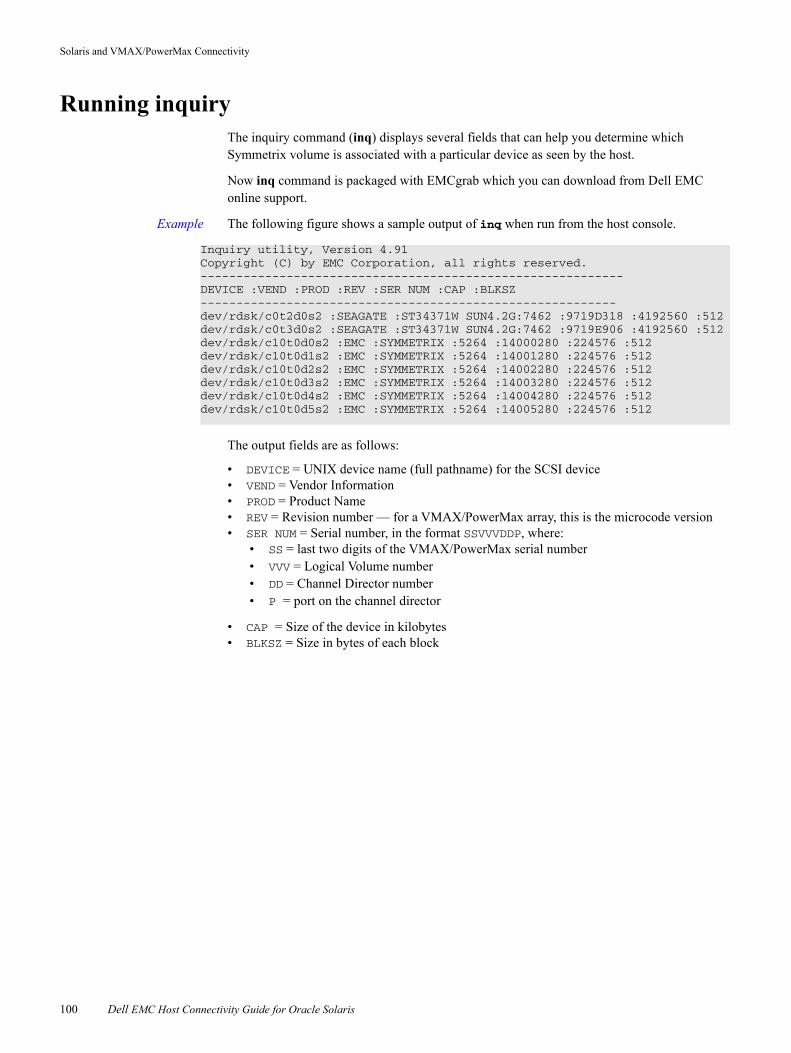
Solaris and VMAX/PowerMax Connectivity
Running inquiryThe inquiry command (inq) displays several fields that can help you determine which Symmetrix volume is associated with a particular device as seen by the host.
Now inq command is packaged with EMCgrab which you can download from Dell EMC online support.
Example The following figure shows a sample output of inq when run from the host console.
The output fields are as follows:
• DEVICE = UNIX device name (full pathname) for the SCSI device• VEND = Vendor Information• PROD = Product Name• REV = Revision number — for a VMAX/PowerMax array, this is the microcode version• SER NUM = Serial number, in the format SSVVVDDP, where:
• SS = last two digits of the VMAX/PowerMax serial number• VVV = Logical Volume number• DD = Channel Director number• P = port on the channel director
• CAP = Size of the device in kilobytes• BLKSZ = Size in bytes of each block
Inquiry utility, Version 4.91Copyright (C) by EMC Corporation, all rights reserved.-----------------------------------------------------------DEVICE :VEND :PROD :REV :SER NUM :CAP :BLKSZ----------------------------------------------------------dev/rdsk/c0t2d0s2 :SEAGATE :ST34371W SUN4.2G:7462 :9719D318 :4192560 :512dev/rdsk/c0t3d0s2 :SEAGATE :ST34371W SUN4.2G:7462 :9719E906 :4192560 :512dev/rdsk/c10t0d0s2 :EMC :SYMMETRIX :5264 :14000280 :224576 :512dev/rdsk/c10t0d1s2 :EMC :SYMMETRIX :5264 :14001280 :224576 :512dev/rdsk/c10t0d2s2 :EMC :SYMMETRIX :5264 :14002280 :224576 :512dev/rdsk/c10t0d3s2 :EMC :SYMMETRIX :5264 :14003280 :224576 :512dev/rdsk/c10t0d4s2 :EMC :SYMMETRIX :5264 :14004280 :224576 :512dev/rdsk/c10t0d5s2 :EMC :SYMMETRIX :5264 :14005280 :224576 :512
100 Dell EMC Host Connectivity Guide for Oracle Solaris
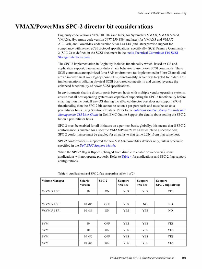
Solaris and VMAX/PowerMax Connectivity
VMAX/PowerMax SPC-2 director bit considerationsEnginuity code versions 5874.101.102 (and later) for Symmetrix VMAX, VMAX V2and VMAXe, Hypermax code version 5977.250.189 (and later) for VMAX3 and VMAX All-Flash, and PowerMax code version 5978.144.144 (and later) provide support for compliance with newer SCSI protocol specifications, specifically, SCSI Primary Commands - 2 (SPC-2) as defined in the SCSI document in the incits Technical Committee T10 SCSI Storage Interfaces page.
The SPC-2 implementation in Enginuity includes functionality which, based on OS and application support, can enhance disk- attach behavior to use newer SCSI commands. These SCSI commands are optimized for a SAN environment (as implemented in Fibre Channel) and are an improvement over legacy (non SPC-2) functionality, which was targeted for older SCSI implementations utilizing physical SCSI bus-based connectivity and cannot leverage the enhanced functionality of newer SCSI specifications.
In environments sharing director ports between hosts with multiple vendor operating systems, ensure that all host operating systems are capable of supporting the SPC-2 functionality before enabling it on the port. If any OS sharing the affected director port does not support SPC-2 functionality, then the SPC-2 bit cannot be set on a per-port basis and must be set on a per-initiator basis using Solutions Enabler. Refer to the Solutions Enabler Array Controls and Management CLI User Guide in Dell EMC Online Support for details about setting the SPC-2 bit on a per-initiator basis.
SPC-2 must be enabled for all initiators on a per-host basis, globally; this means that if SPC-2 conformance is enabled for a specific VMAX/PowerMax LUN visible to a specific host, SPC-2 conformance must be enabled for all paths to that same LUN, from that same host.
SPC-2 conformance is supported for new VMAX/PowerMax devices only, unless otherwise specified in the Dell EMC Support Matrix.
When the SPC-2 flag is flipped (changed from disable to enable or vice-versa), some applications will not operate properly. Refer to Table 4 for applications and SPC-2 flag support configurations.
Table 4 Applications and SPC-2 flag supporting table (1 of 2)
Volume Manager Solaris Version
SPC-2 Support<8k dev
Support>8k dev
Support SPC-2 flip (off/on)
VxVM 5.1 SP1 10 ON YES YES YES
VxVM 5.1 SP1 10 x86 OFF YES NO NO
VxVM 5.1 SP1 10 x86 ON YES YES NO
SVM 10 OFF YES YES YES
SVM 10 ON YES YES YES
SVM 10 x86 OFF YES YES YES
SVM 10 x86 ON YES YES YES
VMAX/PowerMax SPC-2 director bit considerations 101

Solaris and VMAX/PowerMax Connectivity
ZFS 10 OFF YES YES YES
ZFS 10 ON YES YES YES
ZFS 10 x86 OFF YES YES YES
ZFS 10 x86 ON YES YES YES
Table 4 Applications and SPC-2 flag supporting table (2 of 2)
Volume Manager Solaris Version
SPC-2 Support<8k dev
Support>8k dev
Support SPC-2 flip (off/on)
102 Dell EMC Host Connectivity Guide for Oracle Solaris

Solaris and VMAX/PowerMax Connectivity
VMAX/PowerMax new features
SRDF Metro
SRDF/Metro changes SRDF behavior to better achieve the high availability requirements of today's applications. In traditional SRDF, only R1 (source) devices are Read/Write accessible to the host, while R2 (target) devices are Read Only/Write Disabled to the host. With SRDF/Metro:
• R2 devices are Read/Write accessible to the host.• Hosts can write to both the R1 and R2 side of the device pair.• R2 devices assume the same external device identity (such as, geometry and device WWN)
as their R1 partners.
Note: SRDF/Metro is supported on a configuration basis. Refer to the DELL EMC VMAX Simple Support Matrix for the most up-to-date support information.
NDM (Non-Disruptive Migration)
Non-Disruptive Data Migration (NDM) is available for VMAX3 and VMAX All Flash storage arrays running HYPERMAX OS 5977 Q3 2016 Service Release or later, PowerMax array running PowerMax OS, and Solutions Enabler 8.3 or later. NDM is designed to help automate the process of migrating hosts and applications to a new VMAX3, VMAX All Flash or PowerMax array with no downtime.
Non-Disruptive Migration leverages VMAX SRDF replication technologies to move the application data to the new array. It also uses VMAX auto-provisioning, in combination with PowerPath or a supported host multipathing solution, to manage host access to the data during the migration process.
Note: Migrations should take place during low IO activity to minimize Performance Impact.
Note: NDM is supported on a configuration basis. Refer to the DELL EMC VMAX Simple Support Matrix for the most up-to-date support information.
ALUA support with Mobility ID (MID)
Arrays running HYPERMAX OS 5977 or higher carry two types of device IDs:
• Compatibility ID• Mobility ID.
Devices with Mobility ID support ALUA failover mode from host. To enable ALUA support for MID devices with native MPxIO on Solaris, Disable the support module for DELL EMC symmetric arrays deleting the following line in ddi_forceload section of /etc/driver/drv/scsi_vhci.conf:
misc/scsi_vhci/scsi_vhci_f_sym_emc,
Note: This affects VMAX CID devices, VPLEX and XtremIO devices. Once ALUA for MID is enabled, these devices are not be managed under MPxIO.
VMAX/PowerMax new features 103

Solaris and VMAX/PowerMax Connectivity
Host configuration with Emulex HBAs
IMPORTANT
Dell EMC does not support FC-IP on Emulex HBAs.
Note: Refer to the Dell EMC Support Matrix for the most up-to-date approved HBAs.
Emulex legacy 8 GB and 16 GB adapters are driven by the emlxs device driver. The emlxs driver is a part of the Oracle StorEdge SAN Foundation Software (also known as Leadville stack driver). This FS driver is embedded in the Solaris 10 Update 1 or later and Solaris 11 operating system.
• The Solaris 10 Update 4 with patch 120223-27 is a minimum version that has been quali-fied for the Emulex 8 GB adapters.
• Solaris 10 Update 8 with Solaris patch 141877-07 is the minimum version that has been qualified for the Emulex OCe10102-FM and OCe10102-FX adapters.
• Solaris 10 Update 9 with Solaris patch 145099-04 is the minimum version that has been qualified for the Emulex OCe11102-FM and OCe11102-FX adapters.
If you intend to use Solaris 10 prior to S10 Update 1, there are two packages, SUNWemlxs and SUNWemlxu, that are required before installing required patch 120223-xx (refer to the Dell EMC Support Matrix for the approval revision). These packages are available on the Oracle Software Downloads page.
To install the Dell EMC-qualified Emulex HBAs into the Solaris host and configure the host connection to the EMC storage array and for specific instructions on setting up that particular hardware, refer to the installation guide that came with the HBA, and that is available from the Oracle Help Center.
To install/upgrade the Firmware for an Emulex legacy adapter, follow the FCA Utilities Reference Manual documentation which is located on the Broadcom Support Documents and Downloads page.
LPe12000-E (8 GB single port PCI Express adapter)
LPe12002-E (8 GB dual port PCI Express adapter)
LPe16000-E (16 GB single port PCIE adapter
LPe16002-E (16 GB dual port PCIE adapter
OCe10102-FM-E (CNA) (Dual-channel, 10GBase-SR, short reach optical)
OCe10102-FX-E (CNA) (Dual-channel, 10GBase-CR, direct attach copper)
OCe11102-FM-E (CNA) (Dual-channel, 10GBase-CR, short reach optical)
OCe11102-FX-E (CNA) (Dual-channel, 10GBase-CR, direct attach copper)
104 Dell EMC Host Connectivity Guide for Oracle Solaris

Solaris and VMAX/PowerMax Connectivity
Host configuration with QLogic HBAs
IMPORTANT
Dell EMC does not support FC-IP on QLogic HBAs.
IMPORTANT
Dell EMC does not support the coexistence of QLA 2300 and Leavdville qlc drivers on the same host.
Note: Refer to the Dell EMC Support Matrix for the most up-to-date approved HBAs.
QLogic legacy 8 GB, 10 GB, and 16 GB adapters are driven by the qlc device driver. The qlc driver is a part of the Oracle StorEdge SAN Foundation Software (also known as Sun SAN). This FS is embedded in the Solaris 10 and Solaris 11.
• The Solaris 10 Update 4 with patch 120225-10 is a minimum version that has been quali-fied for QLogic 8 GB adapters.
• Solaris 10 Update 8 with patch 142085-04 is the miniimum version that has been qualified for QLogic QLE814x and QLE815x adapters.
• Solaris 10 Update 9 with Solaris patch 146490-05 is the minimum version that has been qualified for the QLogic QLE824x and QLE825x adapters.
To install the Dell EMC-qualified QLogic HBAs into the Solaris host and configure the host connection to the Dell EMC storage array and for specific instructions on setting up that particular hardware, refer to the installation guide that came with the HBA, and that is available from the Oracle Help Center.
QLE2560-E-SP (8 GB single port PCI Express adapter)
QLE2562-E-SP (8 GB dual port PCI Express adapter)
QLE2670-E-SP (16 GB single port PCI Express adapter)
QLE2672-E-SP (16 GB dual port PCI Express adapter)
QLE8140-SR-E-SP (10 GB single port PCI Express adapter)
QLE8142-SR-E-SP (10 GB dualport PCI Express adapter)
QLE8150-CU-E-SP (10 GB single port PCI Express adapter)
QLE8152-CU-E-SP (10 GB single port PCI Express adapter)
QLE8240-SR-E-SP (10 GB single port PCI Express adapter)
QLE8242-SR-E-SP (10 GB dual port PCI Express adapter)
QLE8250-CU-E-SP (10 GB single port PCI Express adapter)
QLE8252-CU-E-SP (10 GB single port PCI Express adapter)
Host configuration with QLogic HBAs 105

Solaris and VMAX/PowerMax Connectivity
106 Dell EMC Host Connectivity Guide for Oracle Solaris

CHAPTER 8Invisible Body Tag
This chapter provides information specific to Oracle Solaris hosts connecting to VNX/Unity series systems.
• Solaris in a VNX/Unity series environment 108• VNX/Unity series configuration 109• VNX/Unity series and Solaris FC environment 110• Making LUNs available to Solaris 112• Methods for reassigning LUN ownership 115• Updating disk names after reassigning LUNs 116• Examples — Manually reassigning LUNs 117
Solaris and VNX/Unity Connectivity
Solaris and VNX/Unity Connectivity 107

Solaris and VNX/Unity Connectivity
Solaris in a VNX/Unity series environmentThis section lists some VNX/Unity series and Fibre Channel support information specific to the Solaris environment.
Host connectivity
Refer to the Dell EMC Support Matrix or contact your EMC representative for the latest information on qualified hosts and host bus adapters.
Boot device support
Oracle Solaris has been qualified for booting from VNX/Unity series arrays as described in the Dell EMC Support Matrix and the following HBA documents:
• EMC Fibre Channel with Emulex Host Bus Adapters in the Solaris Environment, which is available on Dell EMC Online Support, as described in “Host configuration with Emulex HBAs” on page 104.
• EMC Fibre Channel with QLogic Host Bus Adapters in the Solaris Environment, which is available on Dell EMC Online Support, as described in “Host configuration with QLogic HBAs” on page 105.
Logical devices
Solaris supports up to 255 LUNs per target. The VNX series or Unity series presents up to 256 LUNs.
The logical devices presented by VNX/Unity systems are the same on each Storage Processor (SP). A logical unit (LU) reports itself Device Ready on one SP and Device Not Ready on the other SP.
108 Dell EMC Host Connectivity Guide for Oracle Solaris

Solaris and VNX/Unity Connectivity
VNX/Unity series configurationThis section contains information that will help with the installation, use, and management of the storage system. It also contains information that could adversely affect the performance of the storage system if any listed workaround or fix is not implemented.
VNX/Unity failover mode settings
VNX/Unity series arrays provide five failover modes: 0, 1, 2, 3, and 4. In the Solaris environment, these five modes are supported with restrictions based on the RAID type of the VNX series or Unity logical devices and multipath applications. Table 5 lists the recommended failover mode for each multipath application.
Table 5 Recommended failover modes
VNX/Unity series
failover mode
Logical Volume RAID
Virtual Provisioning (thin
device)
PowerPath Veritas DMP MPxIO
0 0, 1/0, 1, 3, 5, 6 VRAID No No No
1 0, 1/0, 1, 3, 5, 6 VRAID Yes Yes Yes a
2 0, 1/0, 1, 3, 5, 6 VRAID No Yes b No
3 0, 1/0, 1, 3, 5, 6 VRAID No No No
4 0, 1/0, 1, 3, 5, 6 VRAID Yes Yes c Yes
a. Logical Volume RAID 6 and VRAID are not supported in MPxIO with failover mode 0, 1, 2, and 3.
b. Dell EMC supports failover mode 2 with VxVM 4.1 and older versions.
c. VxVM 5.1 SP1 is the minimum version that supports DMP with failover mode 4 (ALUA mode).
VNX/Unity series configuration 109
Solaris and VNX/Unity Connectivity
VNX/Unity series and Solaris FC environmentThis section lists some VNX/Unity series Fibre Channel support information specific to the Solaris SPARC environment.
Software
The Fibre Channel adapter driver functions as a device driver layer below the standard sd or ssd Solaris SCSI adapter driver. The Fibre Channel interface is therefore transparent to the Solaris disk administration system.
Addressing
Oracle uses SCSI-2 device access protocol in addressing Fibre Channel devices, up to 256 (1 to 255) LUNs per host bus adapter (HBA) port for the sd driver. For ssd driver, Solaris can address up to 4096 (0 to 4095) LUNs per HBA port.
System settings
Dell EMC recommends that the /etc/system file be modified to include the following parameters:
1. Set io_time to 30 seconds.
set sd:sd_io_time = 30set ssd:ssd_io_time = 30
This setting prevents the host from issuing warning messages while non-disruptive operations are performed on the Dell EMC storage system.
2. Set max_throttle to 20:
set sd:sd_max_throttle = 20set ssd:ssd_max_throttle = 20
This setting prevents the host from over-sending tag queuing commands which may cause scsi cmd timeout and scsi bus reset:
A maximum throttle setting of 20 means that each host device instance will have no more than 20 commands outstanding (incomplete IOs from the standpoint of the operating system) at any given time.
The value of 20 was determined by testing the incremental gains of increasing queue depth. We discovered that a queue depth of 20 represents a point where negligible incremental performance gains will usually be reached. We do not recommend to additionally offload IO onto the stack, thereby unnecessarily using up resources throughout the stack, for no performance gain. Find a balance.
In the case of meta devices (which have more physical devices on the back-end and can thus physically process more IOs in parallel), it can be beneficial to increase the queue depth to 32.
IMPORTANT
In Solaris, the sd_max_throttle/ssd_max_throttle settings are global, so all devices including non-meta devices will also be affected.
110 Dell EMC Host Connectivity Guide for Oracle Solaris
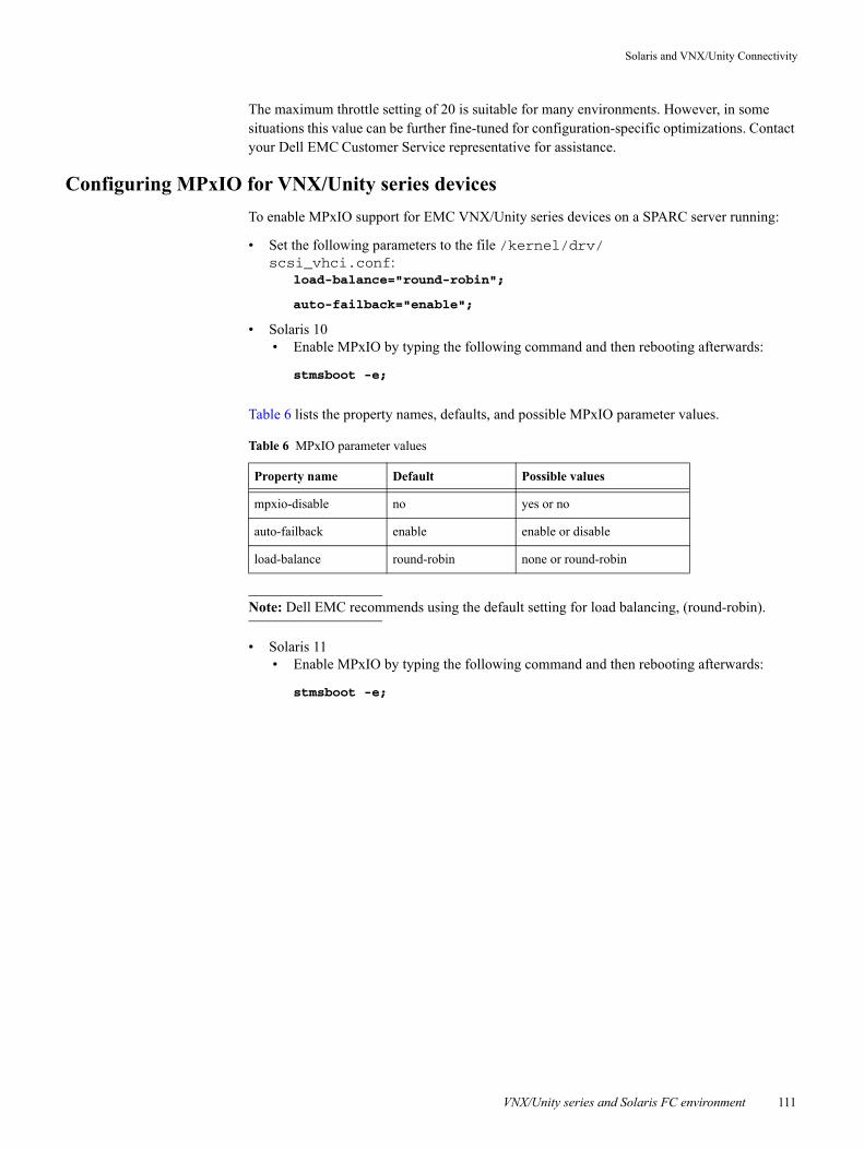
Solaris and VNX/Unity Connectivity
The maximum throttle setting of 20 is suitable for many environments. However, in some situations this value can be further fine-tuned for configuration-specific optimizations. Contact your Dell EMC Customer Service representative for assistance.
Configuring MPxIO for VNX/Unity series devices
To enable MPxIO support for EMC VNX/Unity series devices on a SPARC server running:
• Set the following parameters to the file /kernel/drv/scsi_vhci.conf:
load-balance="round-robin";
auto-failback="enable";
• Solaris 10• Enable MPxIO by typing the following command and then rebooting afterwards:
stmsboot -e;
Table 6 lists the property names, defaults, and possible MPxIO parameter values.
Note: Dell EMC recommends using the default setting for load balancing, (round-robin).
• Solaris 11• Enable MPxIO by typing the following command and then rebooting afterwards:
stmsboot -e;
Table 6 MPxIO parameter values
Property name Default Possible values
mpxio-disable no yes or no
auto-failback enable enable or disable
load-balance round-robin none or round-robin
VNX/Unity series and Solaris FC environment 111

Solaris and VNX/Unity Connectivity
Making LUNs available to SolarisThis section describes how to specify Solaris disk names for LUNs and describes the following tasks that you must perform to make LUNs in the server’s storage group available to Solaris.
Specifying Solaris disk names for LUNs
For Solaris, diskname has the format
cDtSdLsP
where:
• D is the number of the HBA in the server (controller number). Solaris assigns these numbers.
For example, the number for an HBA in slot 1 is 0; for an HBA in slot 2, it is 1. Under some conditions, Solaris may assign other numbers to HBAs.
• S is the target ID (0 through 125) of the SP connected to HBA cD.
• L is the LUN number (0 through 255).
• P is the partition number on the target.
For example, if the HBA is 1, the target ID of the SP is 0, and the LUN number is 2, you would format the disk by typing the following command:
format c1t0d2
What next? Continue to the next section to label and partition the LUNs.
Partitioning and labeling LUNs
This section describes how to use the format command to partition and label LUNs. The version of the format command that ships with Solaris has an auto-configure option that configures LUNs (disks) for you.
1. At the root prompt, type the following command:
format diskname
where diskname is in the form explained under “Specifying Solaris disk names for LUNs”. If you use the format command with no arguments, it displays all disks.
2. From the Format menu, select Available Drive Types.
3. At the Specify disk type prompt, Enter 0 to select the auto-configure option.
4. If you want to partition the disk, use the format command again.
See the Solaris documentation for information on the format command.
5. If you have not labeled the disk, label it using the label command.
Refer to the Solaris documentation for information on the label command.
What next? Continue to the next section to make file systems on the LUN partitions.
112 Dell EMC Host Connectivity Guide for Oracle Solaris
Solaris and VNX/Unity Connectivity
Making file systems on partitions
Use the newfs command to make file systems on all newly created partitions. You must specify a character device name to indicate the partition where you want to create the file system.
For example, to make a file system on partition 0 on the first disk (LUN), Enter the following command:
newfs /dev/rdsk/c1t0d0s0
What next? Continue to the next section to mount the file systems.
Mounting file systems
This procedure is the same as for any LUN used with a Solaris operating system. Use the mount command to mount the file systems that you have created on your storage system. You must specify the block device name of the partition where you created the file system, and the mount point directory.
For example, to mount the file system partition 0 of the first disk configured, at the mount point /temp, Type the following command:
mount /dev/dsk/c1t0d0s0 /temp
What next? • To reassign ownership of LUNs, refer to “Methods for reassigning LUN ownership” on page 115.
Verifying that the server can see its LUNs
Use Unisphere/Navisphere Manager to verify that the server can see its LUNs.
1. For each storage system connected to the server, use Unisphere/Navisphere Manager to verify the server can see its LUNs.
a. Select the storage system for management.
b. Click Hosts.
c. Double-click the icon for the Solaris server.
d. Double-click the LUNs icon.
e. Look for an icon for each LUN that the server should have.
2. If an icon for each LUN exists, the persistent bindings are set correctly.
3. If the icon for any LUN is missing, ensure that the LUN belongs to a Storage Group connected to the server as follows:
a. Double-click the Storage Groups icon.
b. Right-click the icon for the storage group that should contain the missing LUN, and then click Properties.
c. In the Storage Group Properties dialog box, look for the missing LUN in the LUNs in Storage Group list.
d. If the LUN is not listed, click Select LUNs.
Making LUNs available to Solaris 113

Solaris and VNX/Unity Connectivity
e. In the Modify Storage Group dialog box, look for the missing LUN in the Select LUNS for Storage Group list.
f. If the LUN is not listed, click Show LUNs in Other Storage Groups.
– If the LUN is listed, then move the LUN from its current storage group into the storage group for the server by clicking the right arrow and then clicking OK.
– If the LUN is still not listed, then the LUN is missing from the sd.conf or
ssd.conf file.
114 Dell EMC Host Connectivity Guide for Oracle Solaris

Solaris and VNX/Unity Connectivity
Methods for reassigning LUN ownershipYou can reassign LUN ownership from one SP to another SP by either of the following:
• Manually using Unisphere/Navisphere Manager or trespass_array.• Automatically using the PowerPath software
When you use Unisphere/Navisphere Manager to reassign LUN ownership, you change the default SP owner of the LUN. Neither trespass_array nor PowerPath change the default SP owner of the LUN. When you change ownership of LUNs using Unisphere/Navisphere Manager, the reassignment of the LUN to the other SP does not take effect until you power the storage system off and then on again. For this reason, EMC recommends that you use Unisphere/Navisphere Manager to reassign LUN ownership in non-failure situations only when:
• You add a second SP and you want to assign LUNs to the new SP. • You add LUNs and you want to balance your LUNs between two SPs.
When an SP or a component (cable or adapter) in the path to an SP fails, the process of reassigning LUNs from the failed SP to the working SP is called a failover. If PowerPath is running and a failure occurs, PowerPath will automatically execute a failover. If PowerPath is not installed, and the working SP owns at least one LUN, you can fail over LUNs to the working SP using trespass_array. When you replace the failed SP or component, manually restore the LUN that failed over to its original SP using either the trespass_array command.
Failover using PowerPath
Note: PowerPath is required if your server has two HBAs connected to a storage system.
PowerPath automatically reassigns LUNs when a failure occurs. This lets applications continue to run with minimal interruption after an FC-AL or fabric route fails.
Note: If your system is booted with a path removed, PowerPath will fail over the affected LUNs and allow I/O to take place to these LUNs. When the path is restored, PowerPath will automatically restore these LUNs.
Methods for reassigning LUN ownership 115
Solaris and VNX/Unity Connectivity
Updating disk names after reassigning LUNsFor Solaris, a change in LUN ownership affects disk names according to the type of SP failure that occurs; that is, if an SP fails or if you change SP ownership manually.
Updating disk names if an SP fails
If an SP fails, you cannot access the LUNs on the failed SP. At this point, disk names remain unchanged. However, the next time you boot the server, you must use the boot -r command, which changes the disk names to reflect the new target ID (the tS portion of the disk name). In a dual-adapter configuration, the disk names also reflect the new adapter (the cD portion of the disk name).
Updating disk names if you manually change LUN ownership
Manually changing LUN ownership affects disk names. You must power down and reboot the server after manually changing LUN ownership:
1. Shut down the server’s operating system.
2. Power off and power on the storage system.
3. Shut down the server.
4. Reboot the server using the boot -r command.
Now the disk names reflect the new target (the tS portion of the disk name). In a dual-adapter configuration, the disk names reflect the new adapter (the cD portion of the disk name).
116 Dell EMC Host Connectivity Guide for Oracle Solaris
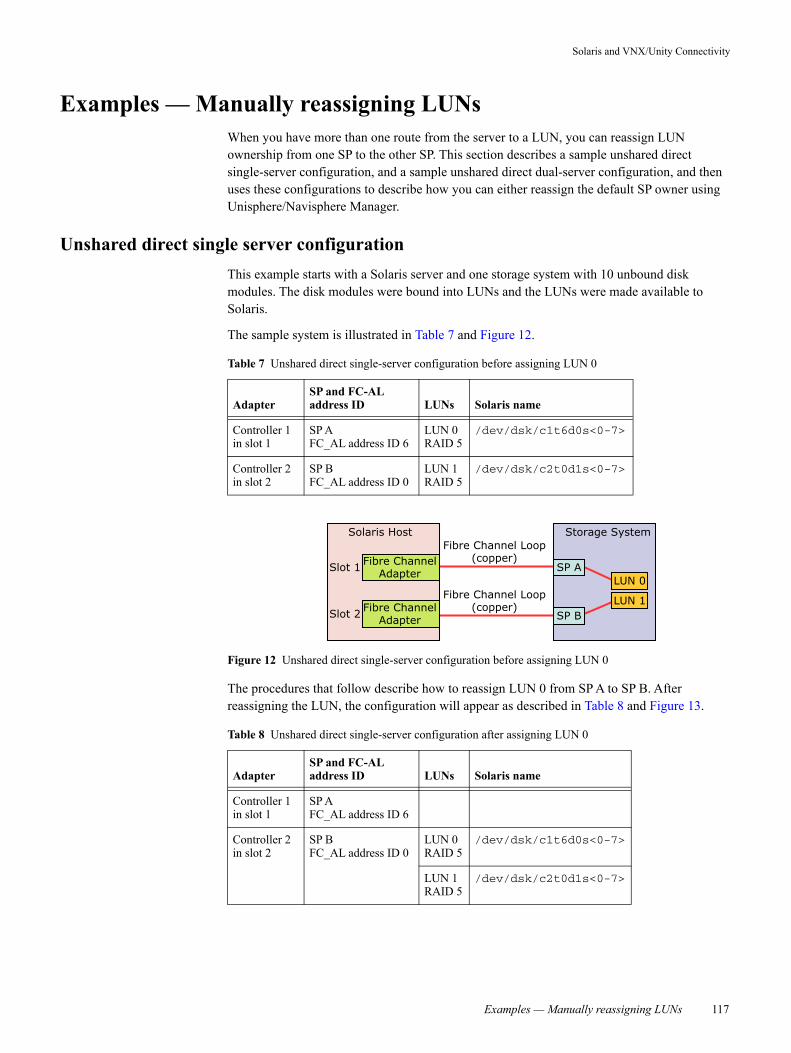
Solaris and VNX/Unity Connectivity
Examples — Manually reassigning LUNs When you have more than one route from the server to a LUN, you can reassign LUN ownership from one SP to the other SP. This section describes a sample unshared direct single-server configuration, and a sample unshared direct dual-server configuration, and then uses these configurations to describe how you can either reassign the default SP owner using Unisphere/Navisphere Manager.
Unshared direct single server configuration
This example starts with a Solaris server and one storage system with 10 unbound disk modules. The disk modules were bound into LUNs and the LUNs were made available to Solaris.
The sample system is illustrated in Table 7 and Figure 12.
Figure 12 Unshared direct single-server configuration before assigning LUN 0
The procedures that follow describe how to reassign LUN 0 from SP A to SP B. After reassigning the LUN, the configuration will appear as described in Table 8 and Figure 13.
Table 7 Unshared direct single-server configuration before assigning LUN 0
AdapterSP and FC-AL address ID LUNs Solaris name
Controller 1in slot 1
SP AFC_AL address ID 6
LUN 0RAID 5
/dev/dsk/c1t6d0s<0-7>
Controller 2in slot 2
SP BFC_AL address ID 0
LUN 1RAID 5
/dev/dsk/c2t0d1s<0-7>
Solaris Host Storage System
Fibre ChannelAdapter
Slot 1
Fibre ChannelAdapter
Slot 2
LUN 0
LUN 1
SP A
SP B
Fibre Channel Loop(copper)
Fibre Channel Loop(copper)
Table 8 Unshared direct single-server configuration after assigning LUN 0
AdapterSP and FC-AL address ID LUNs Solaris name
Controller 1in slot 1
SP AFC_AL address ID 6
Controller 2in slot 2
SP BFC_AL address ID 0
LUN 0RAID 5
/dev/dsk/c1t6d0s<0-7>
LUN 1RAID 5
/dev/dsk/c2t0d1s<0-7>
Examples — Manually reassigning LUNs 117

Solaris and VNX/Unity Connectivity
Figure 13 Unshared direct single-server configuration after assigning LUN 0
Reassigning LUN ownership using Unisphere/Navisphere Manager
If you have added LUNs, you can use Unisphere/Navisphere Manager to balance the load and reassign the default SP ownership for some LUNs. The new configuration will take effect only after you turn the power to the storage system off and on.
This procedure is not intended to temporarily reassign LUNs when a problem occurs. If a path or SP fails, use either PowerPath to automatically fail over LUNs or trespass_array to manually fail over LUNs.
This section describes how to reassign the default ownership of a LUN from one SP to another SP using the unshared direct configuration. The example reassigns LUN 0, /dev/dsk/c1t6d0s0 mounted at /mount1a, from SP A to SP B.
1. Unmount the file system on the LUN to be reassigned.
To unmount the file system, use the umount command. For example, if the mount point is /mount1a, type this command:
umount /mount1a
Note: If you cannot unmount the file system, run fsck on your file system.
2. Change the SP ownership as described in the Unisphere or Navisphere Manager manual.
3. Halt the server by typing:
shutdown -y -i0 -g0
4. Power the storage system off and on.
5. At the OK> prompt, reboot the server by typing:
boot -r
Rebooting enables the operating system to recognize that a device exists.
6. If necessary, run fsck on your file system. You may not need to run fsck if you were able to unmount the file system in step 1.
7. Mount and use the file system on the new LUN.
In step 1, we used the example mount point /mount1a. Although the new LUN has a different name, mount the partition on /mount1a so that users can still use the pathnames to which they are accustomed.
LUN 0 is reassigned to SP B.
Storage System
LUN 0
LUN 1
SP A
SP B
Fibre Channel Loop(copper)
Fibre Channel Loop(copper)
Solaris Host
Fibre ChannelAdapter
Slot 1
Fibre ChannelAdapter
Slot 2
118 Dell EMC Host Connectivity Guide for Oracle Solaris

Solaris and VNX/Unity Connectivity
Sample unshared direct dual-server configuration
The unshared direct dual-server configuration has two servers, each with an adapter connected to an SP through a Fibre Channel cable. Each server independently uses its own LUNs in the storage system. For detailed configuration information, see the hardware reference or installation manual that ships with the storage system.
The following example starts with two Solaris servers and one storage system with 10 unbound disk modules that are bound into LUNs and are available to the operating system.
Table 9 and Figure 14 illustrate the example.
Figure 14 Unshared direct dual-server configuration before assigning LUN 0
The procedures that follow describe how to reassign LUN 0 from SP A to SP B. After reassigning LUN 0, the configuration will appear as shown in Table 10 and Figure 15.
Table 9 Unshared direct dual-server configuration before assigning LUN 0
ServersSP and FC-AL address ID LUNs Solaris name
Solaris host 1 SP AFC_AL address ID 6
LUN 0RAID 5
/dev/dsk/c1t6d0s<0-7>
Solaris host 2 SP BFC_AL address ID 0
LUN 1RAID 5
/dev/dsk/c2t0d1s<0-7>
Solaris Host 1
Fibre ChannelAdapter
Solaris Host 2
Fibre ChannelAdapter
Storage System
LUN 0
LUN 2
Fibre Channelor SCSI
Fibre Channelor SCSI
SP BSP A
Table 10 Unshared direct dual-server configuration after assigning LUN 0
ServersSP and FC-AL address ID LUNs Solaris name
Solaris host 1 SP AFC_AL address ID 6
Solaris host 2 SP BFC_AL address ID 0
LUN 0RAID 5
/dev/dsk/c1t6d0s<0-7>
LUN 1RAID 5
/dev/dsk/c2t0d1s<0-7>
Examples — Manually reassigning LUNs 119

Solaris and VNX/Unity Connectivity
Figure 15 Unshared direct dual-server configuration after assigning LUN 0
Reassigning LUN ownership using Unisphere/Navisphere Manager
If you added LUNs, you might want to use Unisphere/Navisphere Manager to balance the load and to reassign the default SP ownership for some LUNs. The new configuration will take effect only after you turn the power to the storage system off and on.
From the sample unshared direct dual-server configuration, we reassign the Solaris host1 RAID 5 LUN /dev/dsk/c1t6d0s0 mounted at /mount1a from SP A to SP B, which is connected to server Solaris host2. Before being reassigned, the LUN is owned by SP A at FC-AL address ID 6, and after it is reassigned, it is owned by SP B at FC-AL address ID 0.
1. On Solaris host1, unmount the mount points for one LUN. In this example we transfer ownership of LUN 0, which has partition device entries /dev/dsk/c1t6d0s0. We unmount file systems on these partitions.
Unmount the file system using the umount command. For example, if the mount point is /mount1a, type:
umount /mount1a
Note: If you cannot unmount the file system, run fsck on your file system.
2. Change the SP ownership as described in the Unisphere or Navisphere Manager manual.
3. Halt both servers by Entering on each:
shutdown -y -i0 -g0
4. Power the storage system off and on.
5. At the OK> prompt, reboot each server by Entering
boot -r
Rebooting enables the operating system to recognize that a device exists.
6. Mount and use the file systems on controller1 on Solaris host2.
Step 1 used the example mount point /mount1a. Although the new LUN has a different name, mount the partition on /mount1a on the new server so that users can still use the pathnames to which they are accustomed.
Solaris Host 1
Fibre ChannelAdapter
Solaris Host 2
Fibre ChannelAdapter
Storage System
LUN 0
LUN 2
Fibre Channelor SCSI
Fibre Channelor SCSI
SP BSP A
120 Dell EMC Host Connectivity Guide for Oracle Solaris

CHAPTER 9Invisible Body Tag
This chapter includes the following sections:
• Solaris and Dell EMC XtremIO environment 122• Oracle VM Server for SPARC 125• Veritas Volume Manager 126• Solaris and XtremIO over Fibre Channel 127• Solaris and XtremIO over iSCSI 128• Multipathing software configuration 132• Configuring PowerPath Multipathing 134• Post configuration using the XtremIO cluster 135
Solaris and XtremIO Storage Connectivity
Solaris and XtremIO Storage Connectivity 121
Solaris and XtremIO Storage Connectivity
Solaris and Dell EMC XtremIO environmentThis section lists some support information for Dell EMC XtremIO™ that is specific to the Solaris environment.
• “Hardware connectivity” on page 122• “Solaris operating system” on page 122• “Boot device support” on page 122• “Solaris host system settings” on page 122• “Configuring XtremIO” on page 124
Hardware connectivity
Refer to the Dell EMC Support Matrix or contact your Dell EMC representative for the latest information on qualified hosts, host bus adapters, and connectivity equipment.
Solaris operating system
Refer to the Dell EMC Support Matrix for required Solaris operating system versions.
Boot device support
Booting from the XtremIO device is available to Solaris hosts as described under "Boot Device Support" in the Dell EMC Support Matrix.
Solaris host system settings
Dell EMC recommends that the /etc/system file be modified to include the following parameters:
• Set io_time to 30 seconds• Solaris x86 host or Solaris 11.4 fresh install:
set sd:sd_io_time = 30
• Solaris SPARC host prior to 11.4:
set ssd:ssd_io_time = 30
This setting prevents the host from issuing warning messages while non-disruptive operations are performed on the XtremIO storage.
• Set maximum IO sizeset maxphys = 0x400000
This also requires increase of the maximum I/O size for the disk driver. The corresponding entry and file for this change are different for different Solaris versions, as follows:
• For Solaris 10 (SPARC):
File: /kernel/drv/ssd.conf
Setting: ssd_max_xfer_size=0x400000;
• For Solaris 10 (x86):
File: /kernel/drv/sd.conf
Setting: sd_max_xfer_size=0x400000;
122 Dell EMC Host Connectivity Guide for Oracle Solaris
Solaris and XtremIO Storage Connectivity
• For Solaris 11 (SPARC) prior to 11.4:
File: /etc/driver/drv/ssd.conf
Setting: ssd_max_xfer_size=0x400000;
• For Solaris 11 (x86) and 11.4 SPARC fresh install:
File: /etc/driver/drv/sd.conf
Setting: sd_max_xfer_size=0x400000;
• Configuring scsi_vhci.conf for Solaris 11The scsi_vhci.conf file is used to configure third-party symmetric storage on the Solaris 11 host. The host sends SCSI inquiry commands and needs to know what strings to expect in return.
To configure the /etc/driver/drv/scsi_vhci.conf file for a Solaris 11 host:
1. Type the following command to verify the scsi_vhci.conf file location:
#ls /etc/driver/drv/
2. If the file is not in the expected location, type the following command to copy it from /kernel/drv:
#cp /kernel/drv/scsi_vhci.conf /etc/driver/drv
3. Run the following commands to create a backup and modify:
#cp -p /etc/driver/drv/scsi_vhci.conf
/etc/driver/drv/scsi_vhci.conf_ORIG
#vi /etc/driver/drv/scsi_vhci.conf
4. Append the following line to the file:
scsi-vhci-failover-override = "XtremIO XtremApp",
"f_sym_emc";
– The following list explains the different fields in the appended line:
scsi-vhci-failover-override - The override field needs to be set since
the default "probe" output is not used.
– XtremIO XtremApp - The VID PID (Vendor ID/Product ID) returned by the storage to a SCSI inquiry command.
o f_sym_emc - Indicates Dell EMC symmetric (Non Asymmetric) multipathing/arrays.
5. Save the scsi_vhci.conf file.
6. Reboot the system to make the configuration take effect.
• Configuring scsi_vhci.conf for Solaris 10:To configure /kernel/drv/scsi_vhci.conf file for a Solaris 10 host:
1. Type the following commands to create a backup and modify:
cp /kernel/drv/scsi_vhci.conf
/kernel/drv/scsi_vhci.conf_ORIG
Solaris and Dell EMC XtremIO environment 123

Solaris and XtremIO Storage Connectivity
vi /kernel/drv/scsi_vhci.conf
2. Append the following lines to the file:
device-type-scsi-options-list = "XtremIO XtremApp",
"symmetric-option";
symmetric-option = 0x1000000;
3. Save the scsi_vhci.conf file.
4. Reboot the system to make the configuration take effect.
Configuring XtremIO
Refer to the appropriate EMC XtremIO Storage Array User Guide, available at Dell EMC Online Support for information on configuring the XtremIO array.
124 Dell EMC Host Connectivity Guide for Oracle Solaris

Solaris and XtremIO Storage Connectivity
Oracle VM Server for SPARCYou can use Oracle VM Server for SPARC (formerly known as LDOMs) partitioning technology to allocate a system's various resources (such as CPUs, memory, and devices) into logical groupings and create multiple logical partitions. Each logical partition will be able to run a full instance of Solaris OS, resource, and identity within a single computer system.
The Oracle VM Server for SPARC can create three local domains, as follows:
• Control domain—Domain in which the OVM server for SPARC runs, enabling you to cre-ate and manage other logical domains and virtualize its resources for other domains.
• Guest domain—Domain that is managed by the control domain and use services (virtual network, virtual console, and virtual disks) from the control domain.
• I/O domain—Domain that has direct access to the physical I/O devices.Boot from SAN (BFS) for OVM server for SPARC is supported on the XtremIO device.
The OVM Server for SPARC manager only runs on SPARC Enterprise T-series and SPARC M-series systems. Refer to the Dell EMC Support Matrix for the specific Oracle server model that supports OVM server for SPARC.
You can obtain the OVM Server for SPARC software from Oracle.com.
Refer to the Release Notes of the OVM Server for SPARC for system firmware and Solaris patches requirements from Oracle.com.
Refer to the OVM Server for SPARC Administration Guide, available from Oracle.com, to install the OVM Server for SPARC software, download system firmware, set up services and logical domains, and learn about many other features of OVM Server for SPARC technology.
IMPORTANT
All EMC software applications, (such as PowerPath, Solutions Enabler, and Naviagent), only support on the domain that has direct access to the Dell EMC storage array, such as control domain and I/O domain.
Oracle VM Server for SPARC 125
Solaris and XtremIO Storage Connectivity
Veritas Volume ManagerVeritas Volume Manager (VxVM) and Veritas File System (VxFS) are tools for disk and file management. VxVM can be used to create logical disks, mirrored and striped volumes. VxFS supports large file systems, file system expansion and a journaling file system.
Refer to the following documents for instructions on installing VxVM and VxFS, as well as creating disk groups, mirror volumes, striped volumes, and other related operations:
• Veritas Volume Manager Installation Guide• Veritas Volume Manager User's Guide• Veritas Volume Manager System Administrator's Guide• Veritas Volume Manager Release Notes• Veritas File System Installation Guide• Veritas File System Administrator's Guide
The above Veritas documentations are available from the Veritas Services and Operations Readiness Tools (SORT) page.
Refer to the Dell EMC Support Matrix for specific Veritas Storage Foundation revisions that support the XtremIO array.
126 Dell EMC Host Connectivity Guide for Oracle Solaris
Solaris and XtremIO Storage Connectivity
Solaris and XtremIO over Fibre ChannelThis section provides the following information specific to Oracle Solaris hosts connecting to XtremIO storage over Fibre Channel.
Software
The Fibre Channel adapter driver functions as a device driver layer below the standard sd or ssd Solaris SCSI adapter driver. The Fibre Channel interface is therefore transparent to the Solaris disk administration system.
Addressing
Solaris supports Fibre Channel device addressing up to 4096 (0 to 4095) LUNs per host bus adapter (HBA) port for the sd driver in Solaris x86 and the ssd driver in Solaris SPARC.
Prerequisites
To install one or more Dell EMC-approved HBAs into a Solaris host, follow the procedures in one of these documents, according to the FC HBA type:
• For Qlogic HBAs -Fibre Channel with QLogic Host Bus Adapters in the Solaris Environ-ment
• For Emulex HBAs - Fibre Channel with Emulex Host Bus Adapters in the Solaris Environ-ment
Refer to these documents to configure the host for connection to the Dell EMC storage arrays over Fibre Channel, including any needed HBA BIOS settings. The documents are available on Dell EMC Online Support.
Solaris and XtremIO over Fibre Channel 127

Solaris and XtremIO Storage Connectivity
Solaris and XtremIO over iSCSIThis section provides information specific to XtremIO iSCSI connectivity implementation details for the Oracle Solaris iSCSI software initiator kernel mode driver.
Hardware
XtremIO iSCSI protocol is supported with Oracle Gigabit Network Interface Cards (NIC) in the direct connect and the IP Switch environments.
Software
Solaris iSCSI driver embedded in the Solaris OS starting Solaris 10 (SPARC & x86). The iSCSI driver is included in the following packages:
• SUNWiscsir—Sun iSCSI Device Driver• SUNWiscsiu—Sun iSCSI Management Utilities• SUNWiscsitgtr—Sun iSCSI Target Device driver• SUNWiscsitgtru—Sun iSCSI Target Management Utilities
Addressing
Solaris iSCSI supports up to 4096 (0 to 4095) LUNs per a network interface port.
Configuring Solaris iSCSI initiators
To configure the Solaris iSCSI initiator, refer to the Oracle document System Administration Guide, available at Oracle.com.
Configuring XtremIO iSCSI targets
Refer to the EMC XtremIO Array User Guide, available at Dell EMC Online Support.
Solaris iSCSI/XtremIO case study
The following is a basic case study that incorporates information of the XtremIO iSCSI and Solaris iSCSI host configurations. Figure 16 shows an example used in this section.
Figure 16 Host iSCSI initiators connect to XtremIO iSCSI targets via IP switch
128 Dell EMC Host Connectivity Guide for Oracle Solaris

Solaris and XtremIO Storage Connectivity
XtremIO iSCSI configuration
From XtremIO Storage Management Application, select Administration > iSCSI Network Configuration.
Set up the target ports as follows:
X1-SC1-iscsi1 IP/Subnet bits=20.10.10.5/24 Port=3260 VLAN=0X1-SC2-iscsi1 IP/Subnet bits=20.10.11.5/24 Port=3260 VLAN=0
Solaris host iSCSI configuration
This section provides information on both Solaris 10 and Solaris 11 host configuration.
Solaris 10 host configuration
1. Enable the network interface for each GigE Network adapter:
# ifconfig ce0 plumb# ifconfig ce1 plumb
2. Set the IP for each interface:
# ifconfig ce0 20.10.10.10 netmask 255.255.255.0 up# ifconfig ce1 20.10.11.10 netmask 255.255.255.0 up
3. Add netmask value for the interfaces to the file /etc/inet/netmask:
20.10.10.10255.255.255.020.10.11.10255.255.255.0
4. Add IP address of each interface to the file /etc/hosts:
20.10.10.10iSCSI020.10.11.10iSCSI1
5. Create host network file for each interface port:
/etc/hostname.ce0 contains iSCSI0/etc/hostname.ce1 contains iSCSI1
6. You can use the static discovery method or SendTargets device discovery method:
• Configure the static target discovery method:
# iscsiadm add static-config iqn.2008-05.com.xtremio:001e675ba1e8,20.10.10.5:3260# iscsiadm add static-config iqn.2008-05.com.xtremio:001e675b9ba4,20.10.11.5:3260
• Configure the SendTargets device discovery method:
# iscsiadm add discovery-address 20.10.10.5:3260# iscsiadm add discovery-address 20.10.11.5:3260
7. Enable the iSCSI target discovery method.
• If you have configured the static discovery method, enable the static target discovery:
# iscsiadm modify discovery -s enable
• If you have configured the SendTargets discovery method, enable the SendTargets discovery:
# iscsiadm modify discovery -t enable
Solaris and XtremIO over iSCSI 129
Solaris and XtremIO Storage Connectivity
IMPORTANT
You can only enable one discovery method at a time. If both SendTarget and Static discovery methods are enabled at the same time that may cause the host to PANIC.
8. Reboot the host with reconfigure for the changes to take effect:
# reboot -- -r
9. If the host isn't detected to any iSCSI devices, type the following command to create iSCSI device nodes:
# devfsadm -i iscsi
Solaris 11 host configuration
1. Use the dladm show-link command to find out the virtual interface name that associated to ce0 and ce1 (net2 and net3, in this case).
2. Configure IP for the virtual interface net2 and net3:
# svcadm disable network/physical:nwam# svcadm enable network/physical:default# ipadm create-ip net2# ipadm create-addr -T static -a 20.10.10.10/24 net2/v4static# ipadm create-ip net3# ipadm create-addr -T static -a 20.10.11.10/24 net3/v4static# ipadm show-addr
3. You can use the static discovery method or SendTargets device discovery method:
• Configure the static target discovery method:
# iscsiadm add static-config iqn.2008-05.com.xtremio:001e675ba1e8,20.10.10.5:3260# iscsiadm add static-config iqn.2008-05.com.xtremio:001e675b9ba4,20.10.11.5:3260
• Configure the SendTargets device discovery method:
# iscsiadm add discovery-address 20.10.10.5:3260# iscsiadm add discovery-address 20.10.11.5:3260
4. Enable the iSCSI target discovery method.
• If you have configured the static discovery method, enable the static target discovery:
# iscsiadm modify discovery -s enable
• If you have configured the SendTargets discovery method, enable the SendTargets discovery:
# iscsiadm modify discovery -t enable
IMPORTANT
You can only enable one discovery method at a time. If both SendTarget and Static discovery methods are enabled at the same time that may cause OS or system panic to your host.
5. Reboot the host with reconfigure for the changes to take effect:
# reboot -- -r
130 Dell EMC Host Connectivity Guide for Oracle Solaris

Solaris and XtremIO Storage Connectivity
6. If the host is not detected to any iSCSI devices, use the following command to create iSCSI device nodes:
# devfsadm -i iscsi
Solaris and XtremIO over iSCSI 131

Solaris and XtremIO Storage Connectivity
Multipathing software configurationXtremIO supports Solaris Native MultiPathing STMS, Veritas Dynamic Multi-Pathing (DMP), and EMC PowerPath.
Configuring Solaris Native Multipathing STMS
This section describes the required steps for configuring STMS on the Solaris host.
STMS (also known as MPxIO), is the built-in Path Management software used by Solaris operating system.
To configure STMS on the Solaris host:, complete the following steps.
1. Edit the /kernel/drv/scsi_vhci.conf file and set the values of following parameters:
load-balance="round-robin"auto-failback="enable"
2. Add the following option to the /kernel/drv/scsi_vhci.conf file:
• For Solaris 10 (SPARC & x86):
device-type-scsi-options-list ="XtremIO XtremApp", "symmetric-option";
symmetric-option = 0x1000000;
• For Solaris 11/11.1 (SPARC & x86):
scsi-vhci-failover-override = "XtremIO XtremApp", "f_sym_emc";
3. Type the following command to enable the STMS:
stmsboot -e
Note: Select the reboot option for the enable STMS to take effect.
4. To verify STMS is properly configured, run the following command:
stmsboot -L
Configuring Veritas Dynamic MultiPathing (DMP)
1. Disable STMS by modifying the entry mpxio-disable="yes" in the file /kernel/drv/fp.conf.
2. Type the following command:
stmsboot -d
Note: Select the reboot option for the disable STMS to take effect.
3. Install Veritas DMP. Refer to the Veritas Dynamic Multi-Pathing Installation Guide, which is packaged with DMP, for details.
4. Verify that DMP configuration is active, by typing the following DMP commands:
• To display active paths to the XtremIO volumes:
vxdisk path
132 Dell EMC Host Connectivity Guide for Oracle Solaris

Solaris and XtremIO Storage Connectivity
• To display disk information and paths:
vxdisk list <disk_name>
5. To get values for VID and PID by Veritas DMP commands, add XtremIO to the jbod list using the following command:
vxddladm addjbod vid=XtremIO pid=XtremApp policy=aa
Multipathing software configuration 133

Solaris and XtremIO Storage Connectivity
Configuring PowerPath Multipathing
Note: For the most updated information about Dell EMC PowerPathTM support with XtremIO storage, refer to the XtremIO Simple Support Matrix.
XtremIO supports multipathing using PowerPath on Solaris. PowerPath versions 6.0 and above, and provides the Native Loadable Array Module (LAM) for XtremIO Array devices. With this support, XtremIO devices running versions 2.4 and above are managed under the XtremIO class.
PowerPath provides enhanced path management capabilities for up to 32 paths per logical device, as well as intelligent dynamic I/O load-balancing functionalities. Having multiple paths enables the host to access a storage device even if a specific path is unavailable. Multiple paths share the I/O traffic to a storage device, using intelligent load-balancing policies which enhance I/O performance and increase application availability. PowerPath is the recommended multipathing choice.
PowerPath features include:
• Multiple paths—enable higher availability and I/O performance, including the control domain in Solaris LDOM.
• Path management insight capabilities—PowerPath characterizes I/O patterns and helps in diagnosing I/O problems due to flaky paths or unexpected latency values.
Metrics are provided on:
• Read and write—In MB/seconds per LUN• Latency distribution—The high and low watermarks per path• Retries—The number of failed I/Os on a specific path• Autostandby feature—Automatically detects intermittent I/O failures and places paths
into autostandby (also known as flaky paths).• PowerPath Migration Enabler—A host-based migration tool that allows migrating data
between storage systems. PowerPath Migration Enabler works in conjunction with the host operating system (also called Host Copy) and other underlying technologies, such as Open Replicator (OR).
Remote monitoring:
• PowerPath Virtual Appliance 2.0 (vApp 2.0)• SNMP management daemon
Further PowerPath related information:
• For details on the PowerPath releases supported for your Solaris host, refer to the XtremIO Simple Support Matrix.
• For details on native class support with XtremIO for your host, refer to the EMC Power-Path release notes document for the PowerPath version that you are installing.
• For details on installing and configuring PowerPath with XtremIO native class support on your host, refer to the EMC PowerPath on Solaris Installation and Administration Guide for the PowerPath version you are installing. This guide provides the required information for placing XtremIO volumes under PowerPath control.
134 Dell EMC Host Connectivity Guide for Oracle Solaris

Solaris and XtremIO Storage Connectivity
Post configuration using the XtremIO clusterAfter the host configuration is completed, you can use the XtremIO storage from the host. Refer to the appropriate EMC XtremIO Storage Array User Guide, available from Dell EMC Online Support for further information on creating, presenting, and managing volumes accessed from the host via either the GUI or the CLI.
Disk formatting
When creating volumes in XtremIO for a Solaris host, the default Logical Block (LB) size of a new XtremIO volume is 512B. The Logical Block size can be changed to 4 KB.
In general, when the application using this volume has a 4 KB (or multiples of 4 KB) block size, we recommend presenting a volume with a 4 KB block size to a Solaris host for better aligned I/O with the 4 KB block size of the XtremIO cluster. In all other cases, use the 512 KB size.
Disk alignment
Correcting disk alignment requires erasing and restoring data, which can significantly affect performance issues. Therefore, we recommend verifying that the volume is aligned before populating it with customer data.
For proper alignment to the newly allocated volume, format it to an EFI partition and create a partition starting from sector 40. The partition is then aligned in accordance to the EFI label and all I/Os will start with an offset of 40 sectors.
This alignment method is the best practice when used with UFS - Solaris native file system.
Using this method with ZFS results in miss-alignment since ZFS writes metadata to the disk with a different offset. For best usage of ZFS, align the user partition to start from sector 256. Use the following table to determine the start sector for use with the format utility:
Note: In Solaris x86 platform, it is necessary to create the aligned partition via fdisk before creating a file system. Create an aligned disk according to the above table and span the file system on the formatted slice (i.e., slice 2).
File System Start Sector
UFS 40
ZFS 256
Post configuration using the XtremIO cluster 135
Solaris and XtremIO Storage Connectivity
Creating a file system
Create a UFS file system using the newfs command. We recommend creating the file system using the default block size. Using a custom block size with the -b parameter may lead to unexpected behavior.
Note: 4 KB LB volumes are not supported for use with UFS since it does not support a 4096 vector size. When creating the XtremIO volume, verify that it is created using the default 512 LB size.
When creating a ZFS file system, to properly align the file system on the XtremIO volume, align it to start at sector 256. Consider using the ZFS pool configuration to best match your host and application needs.
Note: ZFS file system configuration and management is out of the scope of this document.
To properly configure the ZFS file system, refer to the Oracle ZFS Administration Guide, available at Oracle.com.
136 Dell EMC Host Connectivity Guide for Oracle Solaris

CHAPTER 10Invisible Body Tag
This chapter describes VPLEX-specific configuration in the Solaris environment and contains support information.
• VPLEX overview 138• Prerequisites 139• Configuring Fibre Channel HBAs with VPLEX 140• Provisioning and exporting storage 143• Storage volumes 145• System volumes 147• Required storage system setup 148• Host connectivity 150• Exporting virtual volumes to hosts 151• Front-end paths 154• Configuring Solaris hosts to recognize VPLEX volumes 156• VPLEX and Multipathing software 157• VPLEX with Oracle Solaris Cluster support 160
Solaris and VPLEX connectivity
Solaris and VPLEX connectivity 137

Solaris and VPLEX connectivity
VPLEX overviewThe VPLEX family is a solution for federating Dell EMC and non-Dell EMC storage. The VPLEX family is a hardware and software platform that resides between the servers and heterogeneous storage assets supporting a variety of arrays from various vendors. VPLEX can extend data over distance within, between, and across data centers. VPLEX simplifies storage management by allowing LUNs, provisioned from various arrays, to be managed through a centralized management interface.
For more details about configuration and administration operations, refer to the following EMC VPLEX documentation on Dell EMC Online Support:
• EMC VPLEX GeoSynchrony Product Guide• EMC VPLEX GeoSynchrony CLI Guide• EMC VPLEX GeoSynchrony Configuration Guide• EMC VPLEX Hardware Installation Guide• EMC VPLEX Release Notes• Implementation and Planning Best Practices for EMC VPLEX Technical Notes• VPLEX Procedure Generator• VPLEX online help, available on the Management Console GUI• Dell EMC Simple Support Matrix, VPLEX and GeoSynchrony, available from Dell EMC
E-Lab Navigator.
For the most up-to-date support information, refer to the Dell EMC Support Matrix.
138 Dell EMC Host Connectivity Guide for Oracle Solaris

Solaris and VPLEX connectivity
PrerequisitesBefore configuring VPLEX in the Solaris environment, complete the following on each host:
• Confirm that all necessary remediation has been completed.This ensures that OS-specific patches and software on all hosts in the VPLEX environment are at supported levels according to the Dell EMC Support Matrix.
• Confirm that each host is running VPLEX-supported failover software and has at least one available path to each VPLEX fabric.
Note: Always refer to the Dell EMC Support Matrix for the most up-to-date support information and prerequisites.
• If a host is running PowerPath, confirm that the load-balancing and failover policy is set to Adaptive.
• To run DMP, VPLEX 5.0 and Veritas 5.1 with the appropriate asl package are required. To improve the way DMP handles transient errors at the VPLEX array in certain failure scenarios, the following attributes must be changed from the default value:
• dmp_lun_retry_timeout for the VPLEX array to 60 seconds using the following command:
vxdmpadm setattr enclosure emc-vplex0 dmp_lun_retry_timeout=60
• recoveryoption to throttle and iotimeout to 30 using the following command:
vxdmpadm setattr enclosure emc-vplex0 recoveryoption=throttle iotimeout=30
IMPORTANT
For optimal performance in an application or database environment, ensure alignment of your host's operating system partitions to a 32 KB block boundary.
Prerequisites 139
Solaris and VPLEX connectivity
Configuring Fibre Channel HBAs with VPLEXThis section provides Fibre Channel HBA-related configuration details that must be addressed when using Fibre Channel with VPLEX.
The values provided are required and optimal for most scenarios. However, in extreme scenarios the values might need to be tuned if the performance of the VPLEX shows high front-end latency in the absence of high back-end latency and this has visible impact on host applications. This might be an indication that there are too many outstanding IOs at a given time per port. For further information on how to monitor VPLEX performance, refer to the "Performance and Monitoring" section of the VPLEX Administration Guide, located on Dell EMC Online Support. If the host application(s) is seeing a performance issue with the required settings, contact Dell EMC Support for further recommendations.
This section includes the following information:
• “Prerequisites” on page 140• “Setting execution throttle for QLogic” on page 140• “Setting target queue depth for Emulex” on page 141• “To set the target depth on the Emulex FC HBA, complete the following steps:” on
page 141
Prerequisites
To install one or more Dell EMC-approved HBAs into a Solaris host, follow the procedures in the appropriate documents listed below, according to the Fibre Channel HBA type. Refer to these documents, available at Dell EMC Online Support, to configure the host for connection to the Dell EMC Storage Arrays over a Fibre Channel, including any needed HBA BIOS settings.
For Qlogic HBAs
EMC Fibre Channel with QLogic Host Bus Adapters in the Solaris Environment
For Emulex HBAs
EMC Fibre Channel with Emulex Host Bus Adapters in the Solaris Environment
Setting execution throttle for QLogic
The execution throttle setting controls the amount of outstanding I/O requests per HBA port. he HBA execution throttle should be set to the QLogic default value, which is 32. This can be done on the HBA firmware level using CLI.
Set the QLogic HBA adapter Execution Throttle to its default value of 32.
Follow the appropriate procedure according to the HBA type. For any additional information, refer to the HBA vendor's documentation.
140 Dell EMC Host Connectivity Guide for Oracle Solaris
Solaris and VPLEX connectivity
To set the execution throttle on the QLogic FC HBA, complete the following steps:
1. Set the parameters as follows:
• Solaris 10:
In /kernel/drv/qlc.conf, by using any available editor:
execution-throttle=32
• Solaris 11:
Copy /kernel/drv/qlc.conf to /etc/driver/drv/ by using any available editor:
execution-throttle=32
2. Save the changes.
3. Reboot the server (with a standard reboot) to make your changes take effect:
shutdown -r -g0 -y
or
reboot
Setting target queue depth for Emulex
Note: Changing the HBA queue depth is designed for advanced users. Increasing the queue depth may cause hosts to over-stress arrays connected to the Solaris host, resulting in performance degradation while communicating with them.
? target-depth: The driver uses this value as the default limit for the number of simultaneous commands to issue to a single target on the loop.
The following details adjust the target-depth setting for Emulex HBAs:
? Set the Emulex HBA adapter Target queue depth in Solaris to 512 (decimal)
For any additional information refer to the HBA vendor's documentation.
To set the target depth on the Emulex FC HBA, complete the following steps:
1. Set the parameters as follows. These values are in decimal.
• Solaris 10:
In /kernel/drv/emlxs.conf, by using any available editor:
target-depth=512
• Solaris 11:
Copy /kernel/drv/emlxs.conf to /etc/driver/drv/ and add the following lines by using any available editor:
target-depth=512
2. Save the changes.
Configuring Fibre Channel HBAs with VPLEX 141

Solaris and VPLEX connectivity
3. Reboot the server (with a standard reboot) to make your changes take effect:
Shutdown -r -g0 -y
or
reboot
142 Dell EMC Host Connectivity Guide for Oracle Solaris
Solaris and VPLEX connectivity
Provisioning and exporting storageThis section provides information for the following:
• “VPLEX with GeoSynchrony v5.x and v6.x” on page 143
VPLEX with GeoSynchrony v5.x and v6.x
To begin using VPLEX, you must provision and export storage so that hosts and applications can use the storage. Storage provisioning and exporting refers to the following tasks required to take a storage volume from a storage array and make it visible to a host:
1. Discover available storage.
2. Claim and name storage volumes.
3. Create extents from the storage volumes.
4. Create devices from the extents.
5. Create virtual volumes on the devices.
6. Create storage views to allow hosts to view specific virtual volumes.
7. Register initiators with VPLEX.
8. Add initiators (hosts), virtual volumes, and VPLEX ports to the storage view.
You can provision storage using the GUI or the CLI. Refer to the EMC VPLEX Management Console Help or the EMC VPLEX CLI Guide, located on Dell EMC Online Support, for more information.
Figure 17 illustrates the provisioning and exporting process.
Provisioning and exporting storage 143

Solaris and VPLEX connectivity
Figure 17 VPLEX provisioning and exporting storage process
VPLEX also allows easy storage provisioning among heterogeneous storage arrays. After a storage array LUN volume is encapsulated within VPLEX, all of its block-level storage is available in a global directory and coherent cache. Any front-end device that is zoned properly can access the storage blocks.
Two methods available for provisioning: EZ provisioning and Advanced provisioning. For more information, refer to the EMC VPLEX GeoSynchrony Product Guide, located on Dell EMC Online Support.
144 Dell EMC Host Connectivity Guide for Oracle Solaris
Solaris and VPLEX connectivity
Storage volumesA storage volume is a LUN exported from an array. When an array is discovered, the storage volumes view shows all exported LUNs on that array. You must claim, and optionally name, these storage volumes before you can use them in a VPLEX cluster. Once claimed, you can divide a storage volume into multiple extents (up to 128), or you can create a single full size extent using the entire capacity of the storage volume.
Note: To claim storage volumes, the GUI supports only the Claim Storage wizard, which assigns a meaningful name to the storage volume. Meaningful names help you associate a storage volume with a specific storage array and LUN on that array, and helps during troubleshooting and performance analysis.
This section contains the following information:
• “Claiming and naming storage volumes ” on page 145• “Extents ” on page 145• “Devices ” on page 145• “Distributed devices” on page 146• “Rule sets” on page 146
Claiming and naming storage volumes
You must claim storage volumes before you can use them in the cluster (with the exception of the metadata volume, which is created from an unclaimed storage volume). Only after claiming a storage volume, can you use it to create extents, devices, and then virtual volumes.
Extents
An extent is a slice (range of blocks) of a storage volume. You can create a full size extent using the entire capacity of the storage volume, or you can carve the storage volume up into several contiguous slices. Extents are used to create devices, and then virtual volumes.
Devices
Devices combine extents or other devices into one large device with specific RAID techniques, such as mirroring or striping. Devices can only be created from extents or other devices. A device's storage capacity is not available until you create a virtual volume on the device and export that virtual volume to a host.
Storage volumes 145
Solaris and VPLEX connectivity
You can create only one virtual volume per device. There are two types of devices:
• Simple device — A simple device is configured using one component, which is an extent. • Complex device — A complex device has more than one component, combined using a
specific RAID type. The components can be extents or other devices (both simple and com-plex).
Distributed devices
Distributed devices are configured using storage from both clusters and therefore are only used in multi-cluster plexes. A distributed device's components must be other devices and those devices must be created from storage in different clusters in the plex.
Rule sets
Rule sets are predefined rules that determine how a cluster behaves when it loses communication with the other cluster, for example, during an inter-cluster link failure or cluster failure. In these situations, until communication is restored, most I/O workloads require specific sets of virtual volumes to resume on one cluster and remain suspended on the other cluster.
VPLEX provides a Management Console on the management server in each cluster. You can create distributed devices using the GUI or CLI on either management server. The default rule set used by the GUI makes the cluster used to create the distributed device detach during communication problems, allowing I/O to resume at the cluster. For more information, on creating and applying rule sets, refer to the EMC VPLEX CLI Guide, available on Dell EMC Online Support.
146 Dell EMC Host Connectivity Guide for Oracle Solaris
Solaris and VPLEX connectivity
System volumesVPLEX stores configuration and metadata on system volumes created from storage devices. There are two types of system volumes. Each is briefly discussed in this section:
• “Metadata volumes” on page 147• “Logging volumes” on page 147
Metadata volumes
VPLEX maintains its configuration state, referred to as metadata, on storage volumes provided by storage arrays. Each VPLEX cluster maintains its own metadata, which describes the local configuration information for this cluster as well as any distributed configuration information shared between clusters.
For more information about metadata volumes for VPLEX with GeoSynchrony, refer to the EMC VPLEX Product Guide, located on Dell EMC Online Support.
Logging volumes
Logging volumes are created during initial system setup and are required in each cluster to keep track of any blocks written during a loss of connectivity between clusters. After an inter-cluster link is restored, the logging volume is used to synchronize distributed devices by sending only changed blocks over the inter-cluster link.
For more information about logging volumes for VPLEX, refer to the EMC VPLEX with GeoSynchrony Product Guide, located on Dell EMC Online Support.
System volumes 147

Solaris and VPLEX connectivity
Required storage system setupSymmetrix, VNX/Unity series product documentation and installation procedures for connecting a Symmetrix or VNX/Unity series storage system to a VPLEX instance are available on Dell EMC Online Support.
Required Symmetrix FA bit settings
For Symmetrix-to-VPLEX connections, configure the Symmetrix Fibre Channel directors (FAs) as shown in Table 11.
Note: Dell EMC recommends that you download the latest information before installing any server.
1. This must be set if VPLEX is sharing Symmetrix directors with hosts that require conflicting bit settings. For any other configuration, the VCM/ACLX bit can be either set or not set..
Note: When setting up a VPLEX-attach version 5.0 or later with a VNX/Unity series system, the initiator type can be set to Clariion Open and the Failover Mode set to 1 or Failover Mode 4 since ALUA is supported.
If you are using the LUN masking, set the VCM/ACLX flag. If sharing array directors with hosts that require conflicting flag settings, use the VCM/ACLX flag.
Note: The FA bit settings listed in Table 11 are for connectivity of VPLEX to Symmetrix arrays only. For host to Symmetrix FA bit settings, please refer to the Dell EMC Support Matrix.
Supported storage arrays
The Dell EMC Simple Support Matrix lists the storage arrays that have been qualified for use with VPLEX.
Refer to the VPLEX Procedure Generator, available on Dell EMC Online Support, to verify supported storage arrays.
VPLEX automatically discovers storage arrays that are connected to the back-end ports. All arrays connected to each director in the cluster are listed in the storage array view.
Table 11 Required Symmetrix FA bit settings for connection to VPLEX
Set Do not set Optional
SPC-2 Compliance (SPC2)SCSI-3 Compliance (SC3)Enable Point-to-Point (PP)Unique Worldwide Name (UWN)Common Serial Number (C)
Disable Queue Reset on UnitAttention (D)AS/400 Ports Only (AS4)Avoid Reset Broadcast (ARB)Environment Reports to Host (E)Soft Reset (S)Open VMS (OVMS)Return Busy (B)Enable Sunapee (SCL)Sequent Bit (SEQ)Non Participant (N)OS-2007 (OS compliance)
LinkspeedEnable Auto-Negotiation (EAN)VCM/ACLX1
148 Dell EMC Host Connectivity Guide for Oracle Solaris

Solaris and VPLEX connectivity
Initiator settings on back-end arrays
Refer to the VPLEX Procedure Generator, available on Dell EMC Online Support, to verify the initiator settings for storage arrays when configuring the arrays for use with VPLEX.
Required storage system setup 149
Solaris and VPLEX connectivity
Host connectivityFor the most up-to-date information on qualified switches, hosts, host bus adapters, and software, refer to the always consult the Dell EMC Support Matrix (ESM), available through E-Lab Interoperability Navigator (ELN), or contact your Dell EMC Customer Representative.
The latest EMC-approved HBA drivers and software are available for download at the following websites:
• https://www.broadcom.com/• http:/www.qlogic.com
The Dell EMC HBA installation and configurations guides are available at the Dell EMC-specific download pages of these websites.
Note: Direct connect from a host bus adapter to a VPLEX engine is not supported.
150 Dell EMC Host Connectivity Guide for Oracle Solaris

Solaris and VPLEX connectivity
Exporting virtual volumes to hosts You can add a virtual volume to more than one storage view. All hosts included in the storage view will be able to access the virtual volume.
The virtual volumes created on a device or distributed device are not visible to hosts (or initiators) until you add them to a storage view. For failover purposes, two or more front-end VPLEX ports can be grouped together to export the same volumes.
A volume is exported to an initiator as a LUN on one or more front-end port WWNs. Typically, initiators are grouped into initiator groups; all initiators in such a group share the same view on the exported storage (they can see the same volumes by the same LUN numbers on the same WWNs).
An initiator must be registered with VPLEX to see any exported storage. The initiator must also be able to communicate with the front-end ports over a Fibre Channel switch fabric. Direct connect is not supported. Registering an initiator attaches a meaningful name to the WWN, typically the server’s DNS name. This allows you to audit the storage view settings to determine which virtual volumes a specific server can access.
Exporting virtual volumes consists of the following tasks:
1. Creating a storage view, as shown in Figure 18.
Figure 18 Create storage view
Exporting virtual volumes to hosts 151
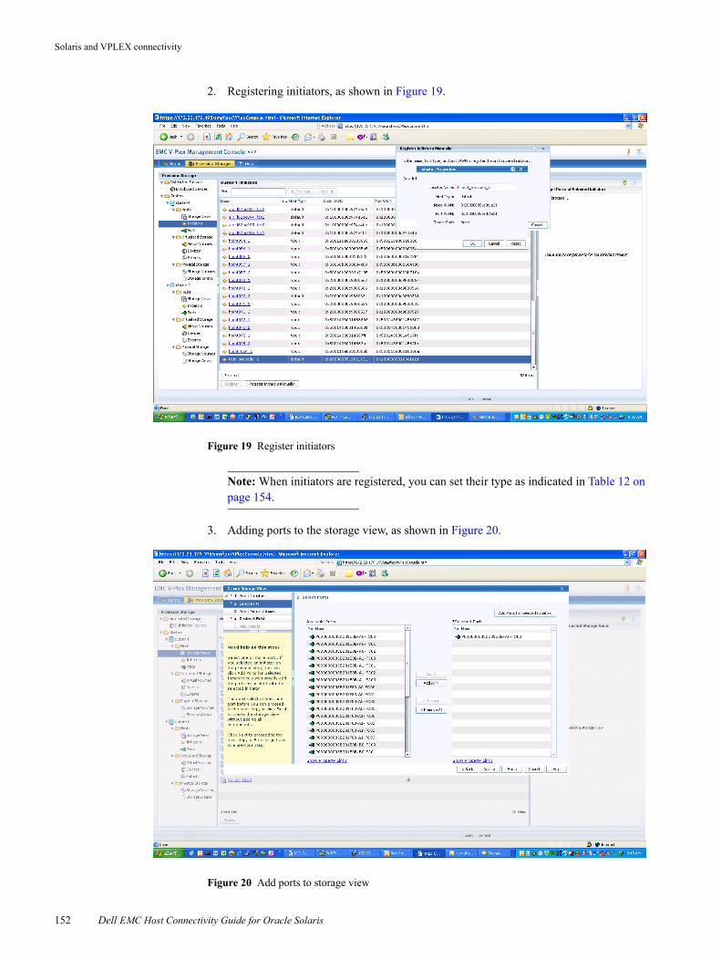
Solaris and VPLEX connectivity
2. Registering initiators, as shown in Figure 19.
Figure 19 Register initiators
Note: When initiators are registered, you can set their type as indicated in Table 12 on page 154.
3. Adding ports to the storage view, as shown in Figure 20.
Figure 20 Add ports to storage view
152 Dell EMC Host Connectivity Guide for Oracle Solaris

Solaris and VPLEX connectivity
4. Adding virtual volumes to the storage view, as shown in Figure 21.
Figure 21 Add virtual volumes to storage view
Exporting virtual volumes to hosts 153
Solaris and VPLEX connectivity
Front-end pathsThis section contains the following information:
• “Viewing the World Wide Name for an HBA port” on page 154• “VPLEX ports” on page 154• “Initiators” on page 154
Viewing the World Wide Name for an HBA port
Each HBA port has a World Wide Name (WWN) associated with it. WWNs are unique identifiers that the VPLEX engine uses to identify its ports and Host Initiators. You can use one of the following ways to view WWNs:
• Switch’s name server output• EMC ControlCenter or Solution Enabler• syminq command (Symmetrix users)
VPLEX ports
The virtual volumes created on a device are not visible to hosts (initiators) until you export them. Virtual volumes are exported to a host through front-end ports on the VPLEX directors and HBA ports on the host/server. For failover purposes, use two or more front-end VPLEX ports to export the same volumes. Typically, to provide maximum redundancy, a storage view will have two VPLEX ports assigned to it, preferably from two different VPLEX directors. When volumes are added to a view, they are exported on all VPLEX ports in the view, using the same LUN numbers.
Initiators
For an initiator to see the virtual volumes in a storage view, it must be registered and included in the storage view's registered initiator list. The initiator must also be able to communicate with the front-end ports over Fibre Channel connections through a fabric.
A volume is exported to an initiator as a LUN on one or more front-end port WWNs. Typically, initiators are grouped so that all initiators in a group share the same view of the exported storage (they can see the same volumes by the same LUN numbers on the same WWN host types).
Ensure that you specify the correct host type in the Host Type column as this attribute cannot be changed in the Initiator Properties dialog box once the registration is complete. To change the host type after registration, you must unregister the initiator and then register it again using the correct host type.
VPLEX supports the host types listed in Table 12. When initiators are registered, you can set their type, also indicated in Table 12.
Table 12 Supported hosts and initiator types
Host Initiator type
Windows, MSCS, Linux default
154 Dell EMC Host Connectivity Guide for Oracle Solaris

Solaris and VPLEX connectivity
AIX Aix
HP-UX Hp-ux
Solaris, VCS Sun-vcs
Table 12 Supported hosts and initiator types
Host Initiator type
Front-end paths 155
Solaris and VPLEX connectivity
Configuring Solaris hosts to recognize VPLEX volumesYou must configure a Solaris host to recognize VPLEX Virtual Volumes. To do this, complete the following steps:
1. Type the following command:
devfsadm -C
2. Use the format command to format and Solaris host with the VPLEX volumes. Those devices have the invista type like the devices of the Invista array.
If you are running volume management software, follow the necessary procedures in your volume management software documentation.
156 Dell EMC Host Connectivity Guide for Oracle Solaris

Solaris and VPLEX connectivity
VPLEX and Multipathing softwareVPLEX can work with PowerPath, DMP, or MPxIO as multipathing software in Oracle Solaris environment, as described briefly in this section.
VPLEX and PowerPath
PowerPath can work with VPLEX devices as a multipathing software in Oracle Solaris host as it does with VMAX/PowerMax or Unity/VNX devices in Active/Active mode.
Refer to Dell EMC Simple Support Matrix for supported PowerPath versions
Refer to Dell EMC Online Support for the PowerPath user guide and other PowerPath support documentation.
VPLEX and DMP
Start with VPLEX 5.0 and VeritasVxVM 5.1, you can use DMP as multipath software in Oracle Solaris host to manage VPLEX devices.
IMPORTANT
Symantec DMP are disabled automatically when PowerPath is installed. Uninstall PowerPath is required if you want to use DMP as host multipath management application.
To use DMP with VPLEX devices, install an addition ASL package from Symantec. You can download the Symantec ASL package for VPLEX can be downloaded from the Veritas Services and Operations Readiness Tools (SORT) page.
Follow the instructions to install ASL as provided by Veritas.
The default path policy is balanced.
Use the following commands to verify ASL installation and the version of ASL:
1. Enable vxdctl and then run the vxddladm list support command to ensure that the ASL is correctly installed.
bash-2.05# vxddladm listsupport libname=libvxInvista.so
ATTR_NAME ATTR_VALUE==================================================================LIBNAME libvxInvista.soVID EMCPID InvistaARRAY_TYPE Inv-A/A, VPLEX-A/AARRAY_NAME EMC_Invista, EMC_VPLEX
2. Verify the ASL version.
bash-2.05# vxddladm listversion libname=libvxInvista.so
LIB_NAME ASL_VERSION Min. VXVM version===================================================================libvxInvista.so vm-5.1-rev-1 5.1
3. After installing the ASL package, a VPLEX device is recognized as follows:
# vxdmpadm list dmpnodedmpdev = emc-vplex0_00b6
VPLEX and Multipathing software 157

Solaris and VPLEX connectivity
state = enabledenclosure = emc-vplex0cab-sno = FNM00094900286asl = libvxInvista.sovid = EMCpid = Invistaarray-name = EMC-VPLEXarray-type = VPLEX-A/Aiopolicy = Balancedavid = 00B6lun-sno = 6000144000000010A001CAAF895253B6udid = EMC%5FInvista%5FFNM00094900286%20%20%5F6000144000000010A001CAAF895253B6dev-attr = -###path = name state type transport ctlr hwpath aportID aportWWN attrpath = c2t500014425001CA10d2s2 enabled(a) - FC c2 /pci@1e,600000/fibre-channel@2/fp@0,0 - 50:00:14:42:50:01:ca:10 -path = c4t500014424001CA10d2s2 disabled - FC c4 /pci@1e,600000/fibre-channel@3/fp@0,0 - 50:00:14:42:40:01:ca:10 -
IMPORTANT
ASL is tightly coupled with the VPLEX SCSI personality. If there is any change in the SCSI personality in the future VPLEX releases, then there should be a corresponding changes in the ASL as applicable.
VPLEX and MPxIO
Beginning with S10u11 and S11.1, you can use the MPxIO as multipath software in Oracle Solaris host to manage VPLEX devices.
Required patches forMPxIO
To use MPxIO with VPLEX devices, the following patches are required:
• For Solaris 11.1 (both Sparc and x86):• SRU 5.5
• For the Solaris S10u11 (1/13) Sparc platform:• 148888-02 (kernel patch)
• 142088-03 (fp/luxadm patch)
• 150115-02 (sd patch)
• For the Solaris S10u11 (1/13) x86 platform:• 148889-02 (kernel patch)
• 142089-03 (fp/luxadm patch)
• 150116-02 (sd patch)
Refer the README file that came with your SRU or patches for detail how to install those patches.
158 Dell EMC Host Connectivity Guide for Oracle Solaris
Solaris and VPLEX connectivity
Enabling MPxIO After the patches are installed, complete the following changes in the host to enable MPxIO:
• With S11.1 OS• Run the following command and reboot:
stmsboot -e
• With S10u11 OS• Set the parameter mpxio_disable in the file /kernel/drv/fp.conf to
mpxio-disable="no"
• You must set the following parameter in the file /kernel/drv/scsi_vhci.conf as:load-balance="round-robin"
auto-failback="enable"
• If you are booting from the internal disk, reboot the host.• If you are booting from the SAN, type the following command from the host:
/usr/sbin/stmsboot -e
Stmsboot enables MPxIO and makes the appropriate changes in your system file (/etc/vfstab) so that you will be able to reboot after MPxIO is enabled since your boot disk's name will change to MPxIO name after the reboot.
If you do not use the stmsboot command, the system may fail to reboot after MPxIO is enabled.
VPLEX and Multipathing software 159
Solaris and VPLEX connectivity
VPLEX with Oracle Solaris Cluster support
VPLEX GeoSynchrony 5.x
The following are supports and limitations when using Solaris Cluster with VPLEX 5.3 and later.
• Operating System and Solaris Cluster revision:• Supports Solaris Cluster 3.3 3/13 (SC 3.3u2) or SC3.3, SC3.3u1, plus the latest cluster
core patch and agents patches with Solaris 10 1/13 (S10u11) and the following minimum Solaris patches:
– Solaris SPARC: 148888-02, 142088-03, 150115-02
– Solaris x86: 148889-02, 142089-03, 150116-02
• Supports Solaris Cluster 4.1 with Solaris 11.1 (SPARC and x86) plus minimum SRU5.5, Solaris Cluster 4.2 with Solaris 11.2 (SPARC and x86), Solaris Cluster 4.3 with Solaris 11.3 (SPARC and x86), and Solaris Cluster 4.4 with Solaris 11.4 (SPARC and x86).
• Requirements and recommendations for support:• Solaris Cluster quorum device must be a configured. It must be a quorum disk that is
part of the VPLEX. The use of a quorum server is not supported. The use of a quorum disk that is not part of the VPLEX is not supported.
• For Solaris Cluster campus cluster configurations, we recommend that the VPLEX array be configured as a geographically-distributed (Metro) system with a VPLEX Witness.
• To reduce the possibility of a common-mode failure, we recommend that the storage devices which make up the VPLEX not be fed from the same power supply or phase (if this is permitted by the electrical code in effect).
• Supports Solaris Cluster using SCSI-2/3 protocol. This includes 2-node and 3-node or more clusters running Solaris Cluster 3.3 and 4.x revisions as defined in the operating system and Solaris Cluster revision bullet, as shown above.
• Supports Solaris Cluster configures in a two-site Campus Cluster.• SCSI reservations in Solaris Cluster:
• Solaris Cluster assumes that all storage devices that support SCSI-3 also will support the APTPL (Activate Persist Through Power Loss) bit of SCSI reservation commands. The use of this option ensures that SCSI registrations and reservations will survive a total power outage of any given storage device.
• VPLEX devices that are supported with Solaris Cluster do not honor the APTPL bit, and a power outage or reset of the whole VPLEX subsystem (both sides of Metro configuration) will cause registrations and reservation keys to be lost. The impact of this depends on whether the Solaris Cluster nodes have also been restarted. In case of single VPLEX node failure, the reservation keys are not lost.
– Cluster nodes unaffected:
If the Solaris Cluster nodes have remained operational, they will continue to access the storage as before, but will not detect the reservation loss unless some other cluster event, such as a node joining or leaving causes the storage access to be re-evaluated. Such access will be unprotected, so data corruption is possible.
160 Dell EMC Host Connectivity Guide for Oracle Solaris

Solaris and VPLEX connectivity
– All cluster nodes also suffering outage:
If all the cluster nodes are impacted by the outage, then when each node reboots it will find that it has no reservation key on the storage and the amnesia protection will prevent it from starting to form a cluster. Only when all nodes have rebooted can a cluster be formed. If one node cannot be restarted for some reason, the cluster will remain offline without manual intervention. The consequence is a loss of service (availability problem) but no data corruption.
• Mitigating the problems:• The clustered, highly-available, nature of VPLEX means that a total outage is unlikely,
especially when storage cluster is geographically distributed.
• The use of a VPLEX LUN as the quorum disk for the Solaris Cluster configuration will ensure that storage split-brain resolution will be performed by the VPLEX, and Solaris Cluster resolution will follow that.
• The Solaris Cluster quorum system regularly polls for SCSI reservations. Loss of reservations for any reason, for example reset or power loss by the storage, will be detected. This will force each cluster node to panic due to loss of quorum. The storage outage will provoke a complete cluster outage, but data will not be corrupted. The subsequent full cluster reboot after resolution of the storage outage will replace the reservations and the cluster will reform, providing that all nodes reboot. If one or more nodes does not reboot, the Solaris Cluster amnesia protection will prevent the formation of a cluster without operator intervention.
• Issues addressed. There are two areas of concern: • When a distributed (campus) configuration is in use, it is essential that any loss of
connectivity between sites (“split-brain”) is resolved in the same way for both Solaris Cluster and VPLEX. A situation where the host cluster selects site A to survive, while the storage cluster selects site B, will result in a total outage.
• A total reset of a complete VPLEX configuration will result in the loss of SCSI-3 reservation keys and registrations. If undetected, this could result in misoperation of the Solaris Cluster software and potential data corruption.
• Additional information• VPLEX is supported with Local topology for Local data center clusters, and Metro
topology for campus cluster configurations.
• When Oracle ASM is in use, the following Oracle and Solaris settings are required:
– Set the Oracle ASM instance parameter _asm_hbeatiowait to 200. Refer to Oracle My Oracle Support (MOS) note 1581684.1 for details and also refer to Oracle bug id: 18554251 for background information.
– Ensure that NTP time synchronization is setup properly on the cluster so that the setting in step 1 above will have the intended effect. Oracle Solaris Cluster software performs NTP synchronization across nodes by default. Refer to the following documents for details for your particular Oracle Solaris Cluster version:
Oracle Solaris Cluster Concepts Guide at Key Concepts for System Administrators and Application Developers > Cluster Time.
Oracle Solaris Cluster Software Installation Guide at Planning the Oracle Solaris Cluster Configuration > Planning the Oracle Solaris Cluster Environment > Network Time Protocol (NTP).
VPLEX with Oracle Solaris Cluster support 161

Solaris and VPLEX connectivity
– Increase the Solaris I/O time from default of 60 to 120 by adding the following line to the /etc/system:
- Solaris SPARC prior to 11.4:
set ssd:ssd_io_time=120
- Solaris x64 or 11.4 SPARC fresh install:
set sd:sd_io_time=120
Refer to Oracle bug id: 18554251 for background information.
– Set Solaris timeout and performance tunings in ssd.conf or sd.conf as follows:
Solaris SPARC prior to 11.4:
ssd-config-list="EMC Invista","cache-nonvolatile:true,disksort:false,retries-busy:12,retries-reset:8,retries-notready:300,retries-timeout:10,throttle-max:32,throttle-min:8";
Solaris x86 or 11.4 SPARC fresh install:
sd-config-list="EMC Invista","cache-nonvolatile:true,disksort:false,retries-busy:12,retries-reset:8,retries-notready:300,retries-timeout:10,throttle-max:32,throttle-min:8";
Note: There should be exactly 5 spaces between “EMC Invista”, for it to work.
If needed, go to Oracle MOS and reference Oracle Support document 1917765.1.
When Solaris ZFS is in use, the following two settings are required for Solaris Cluster to handle failover resource type “HAStoragePlus”:
- Set the zpool failmode to panic
zpool set failmode=panic <zpoolname>
- Set Solaris Cluster resource_dependencies_offline_restart
clrs set -p resource_dependencies_offline_restart=hastorageplus-rs <app-resource>
Where: app-resource is the resource for the data service (application, database, etc.).
Note: Without these two settings, the cluster resource will not failover in case of the VPLEX WAN-com failure.
162 Dell EMC Host Connectivity Guide for Oracle Solaris