emc-series tilting tables use and maintenance manual manual.pdf · rev. 6/16/2015 emc, manual.doc...
TRANSCRIPT
Rev. 6/16/2015 EMC, MANUAL.doc
Copyright 2015 Vestil Manufacturing Co. Page 1 of 13
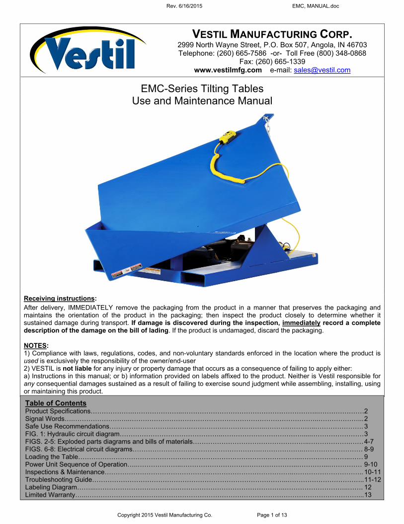
EMC-Series Tilting Tables Use and Maintenance Manual
Receiving instructions:
After delivery, IMMEDIATELY remove the packaging from the product in a manner that preserves the packaging and maintains the orientation of the product in the packaging; then inspect the product closely to determine whether it sustained damage during transport. If damage is discovered during the inspection, immediately record a complete description of the damage on the bill of lading. If the product is undamaged, discard the packaging. NOTES: 1) Compliance with laws, regulations, codes, and non-voluntary standards enforced in the location where the product is used is exclusively the responsibility of the owner/end-user 2) VESTIL is not liable for any injury or property damage that occurs as a consequence of failing to apply either: a) Instructions in this manual; or b) information provided on labels affixed to the product. Neither is Vestil responsible for any consequential damages sustained as a result of failing to exercise sound judgment while assembling, installing, using or maintaining this product.
Table of Contents Product Specifications……………….…………………..……………………………………………………..…………………2 Signal Words….……………………..…………………………………………………………………………..………………... 2 Safe Use Recommendations……………………………………………………………..…………………..…………………. 3 FIG. 1: Hydraulic circuit diagram………………………………………..……………………………….....…………………… 3 FIGS. 2-5: Exploded parts diagrams and bills of materials……………………………………………..……………….…… 4-7 FIGS. 6-8: Electrical circuit diagrams………………………………………………….………………..……………………… 8-9 Loading the Table………………………………………………………………………………………..…………………..…… 9 Power Unit Sequence of Operation…..………………..……………………………………………..…………...…………… 9-10 Inspections & Maintenance…………………………………………………………………………..………………………….. 10-11 Troubleshooting Guide……………………………………………………………………………..…………………………….. 11-12 Labeling Diagram……...…………………………………………………………………………..………………………..……. 12 Limited Warranty…...……………………………………………………………………………………………………………... 13
VESTIL MANUFACTURING CORP. 2999 North Wayne Street, P.O. Box 507, Angola, IN 46703 Telephone: (260) 665-7586 -or- Toll Free (800) 348-0868
Fax: (260) 665-1339 www.vestilmfg.com e-mail: [email protected]

Rev. 6/16/2015 EMC, MANUAL.doc
Copyright 2015 Vestil Manufacturing Co. Page 2 of 13
Product specifications: Dimensions and other product specifications appear in the diagrams and table below.
Model A B C D E F G H Capacity Net weight
EMC-4242-2 59”
42” square
24” 631/2” 12” 361/16” 367/8” 30° 2,000 lb. 909.1 kg
506.4 lb. 230.2 kg
EMC-4242-4 59”
42” square
24” 631/2” 12” 361/16” 367/8” 30° 4,000 lb.
1,818.2 kg 514.6 lb. 233.9 kg
EMC-4848-2 68”
48” square
24” 7113/16” 12” 365/16” 381/2” 30° 2,000 lb. 909.1 kg
576.3 lb. 261.9 kg
EMC-4848-4 68”
48” square
24” 7113/16” 12” 365/16” 381/2” 30° 4,000 lb.
1,818.2 kg 584.5 lb. 265.7 kg
SIGNAL WORDS:
This manual uses SIGNAL WORDS to indicate the likelihood of personal injuries, as well as the probable seriousness of those injuries, if the product is misused in the ways described. Other signal words call attention to uses of the product likely cause property damage. The signal words used appear below along with the meaning of each word:
Identifies a hazardous situation which, if not avoided, WILL result in DEATH or SERIOUS INJURY. Use of this signal word is limited to the most extreme situations.
Identifies a hazardous situation which, if not avoided, COULD result in DEATH or SERIOUS INJURY.
Indicates a hazardous situation which, if not avoided, COULD result in MINOR or MODERATE injury.
Identifies practices likely to result in product/property damage, such as operation that might damage the product.
Each person who assembles, installs, uses, or maintains this product should read the entire manual in advance and fully understand the directions. If after reading the manual you do not understand an instruction, ask your supervisor or employer for clarification, because failure to adhere to the directions in this manual might result in serious personal injury.
Chain bracket
A
B
C
Fork pockets
Standard features: Chrome plated cylinders 3,000psi hydraulic rating
D
E
F G
H
Restraint chain

Rev. 6/16/2015 EMC, MANUAL.doc
Copyright 2015 Vestil Manufacturing Co. Page 3 of 13
Safe Use Recommendations: We strive to identify all hazards associated with the use of our products. However, material handling is dangerous and no manual can address every risk. The end-user ultimately is responsible for exercising sound judgment at all times.
Material handling is dangerous. Improperly or carelessly operating this table might result in serious personal injuries. Failure to read and understand the entire manual before assembling, using or servicing the product constitutes misuse. Read the manual whenever necessary to refresh your understanding of proper use and maintenance procedures. DO NOT use the table unless it is in normal operating condition. Inspect the unit as described in the inspection instructions on p. 10-11 to determine whether it is functioning normally. DO NOT use the machine unless it passes every part of the inspection or until it is restored to normal operating condition. DO NOT use the machine to support people. This table is designed only for material handling. Always watch the tabletop carefully, as well as the load/container, while raising and lowering it. This crane is designed for material handling ONLY. DO NOT use the crane to lift people. ALWAYS load the table properly (see “Loading the table” on p. 9). If repairs are necessary, ONLY install manufacturer-approved replacement parts. The tabletop should move smoothly and evenly. Watch for binding or jerky movement and listen for unusual noises. Remove the unit from service if you observe anything abnormal. DO NOT use this table UNLESS all labels are in place & readable (see “Labeling diagram” on p. 12.) DO NOT modify this product in any way. Modifying the machine automatically voids the limited warranty and might make it unsafe to use.
Proper use and maintenance are essential for this product to function properly. Always use this product in accordance with the instructions in this manual. Periodically lubricate pivot point with bearing grease. Keep the product clean & dry at all times. Always use the unit indoors. Only use approved replacement parts. To order replacement or spare parts for this equipment, contact Vestil. FIG. 1: Hydraulic circuit diagram
Rev. 6/16/2015 EMC, MANUAL.doc
Copyright 2015 Vestil Manufacturing Co. Page 4 of 13
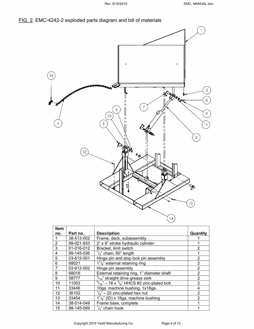
FIG. 2: EMC-4242-2 exploded parts diagram and bill of materials
Item no. Part no. Description Quantity 1 38-513-002 Frame, deck, subassembly 1 2 99-021-933 2” x 8” stroke hydraulic cylinder 1 3 01-016-012 Bracket, limit switch 2 4 99-145-036 1/4” chain, 60” length 1 5 03-612-001 Hinge pin and stop lock pin assembly 2 6 68021 11/8” external retaining ring 2 7 03-612-002 Hinge pin assembly 2 8 68019 External retaining ring, 1” diameter shaft 2 9 58777 3/16” straight drive grease zerk 2 10 11053 5/16” – 18 x 3/4” HHCS #2 zinc-plated bolt 2 11 33446 10ga. machine bushing, 1x18ga. 4 12 36102 1/4” – 20 zinc-plated hex nut 2 13 33454 11/8” (ID) x 18ga. machine bushing 2 14 38-514-049 Frame base, complete 1 15 99-145-069 1/4” chain hook 1

Rev. 6/16/2015 EMC, MANUAL.doc
Copyright 2015 Vestil Manufacturing Co. Page 5 of 13
FIG. 3: EMC-4242-4 exploded parts diagram and bill of materials
Item no. Part no. Description Quantity 1 38-513-002 Frame, deck, subassembly 1 2 99-021-918 3” x 8” stroke hydraulic cylinder 1 3 01-016-012 Bracket, limit switch 2 4 99-145-036 1/4” chain, 60” length 1 5 03-612-001 Hinge pin and stop lock pin assembly 2 6 68021 11/8” external retaining ring 2 7 03-612-002 Hinge pin assembly 2 8 68019 External retaining ring, 1” diameter shaft 2 9 58777 3/16” straight drive grease zerk 2 10 11053 5/16” – 18 x 3/4” HHCS #2 zinc-plated bolt 2 11 33446 10ga. machine bushing, 1x18ga. 4 12 36102 1/4” – 20 zinc-plated hex nut 2 13 33454 11/8” (ID) x 18ga. machine bushing 2 14 38-514-049 Frame base, complete 1 15 99-145-069 1/4” chain hook 1

Rev. 6/16/2015 EMC, MANUAL.doc
Copyright 2015 Vestil Manufacturing Co. Page 6 of 13
FIG. 4: EMC-4848-2 exploded parts diagram and bill of materials
Item no. Part no. Description Quantity 1 38-513-001 Frame, deck, subassembly 1 2 01-016-012 Bracket, limit switch 2 3 03-612-002 Hinge pin assembly 2 4 58777 3/16” straight drive grease zerk 2 5 33446 10ga. machine bushing, 1x18ga. 4 6 68019 External retaining ring, 1” diameter shaft 2 7 03-612-001 Hinge pin and stop lock pin assembly 2 8 33454 11/8” (ID) x 18ga. machine bushing 2 9 68021 11/8” external retaining ring 2 10 36102 1/4” – 20 zinc-plated hex nut 2 11 11053 5/16” – 18 x 3/4” HHCS #2 zinc-plated bolt 2 12 99-145-036 1/4” chain, 60” length 1 13 99-021-933 2” x 8” stroke hydraulic cylinder 1 14 38-514-048 Frame base, complete 1 15 99-145-069 1/4” chain hook 1
Rev. 6/16/2015 EMC, MANUAL.doc
Copyright 2015 Vestil Manufacturing Co. Page 7 of 13
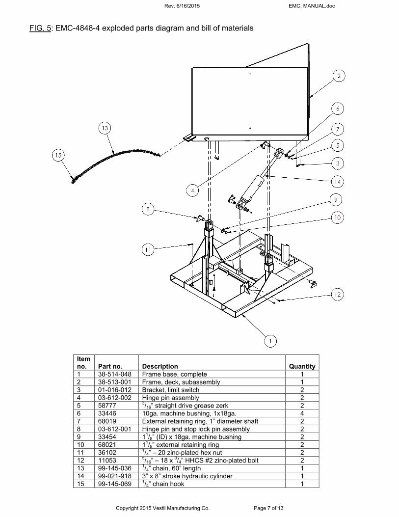
FIG. 5: EMC-4848-4 exploded parts diagram and bill of materials
Item no. Part no. Description Quantity 1 38-514-048 Frame base, complete 1 2 38-513-001 Frame, deck, subassembly 1 3 01-016-012 Bracket, limit switch 2 4 03-612-002 Hinge pin assembly 2 5 58777 3/16” straight drive grease zerk 2 6 33446 10ga. machine bushing, 1x18ga. 4 7 68019 External retaining ring, 1” diameter shaft 2 8 03-612-001 Hinge pin and stop lock pin assembly 2 9 33454 11/8” (ID) x 18ga. machine bushing 2 10 68021 11/8” external retaining ring 2 11 36102 1/4” – 20 zinc-plated hex nut 2 12 11053 5/16” – 18 x 3/4” HHCS #2 zinc-plated bolt 2 13 99-145-036 1/4” chain, 60” length 1 14 99-021-918 3” x 8” stroke hydraulic cylinder 1 15 99-145-069 1/4” chain hook 1

Rev. 6/16/2015 EMC, MANUAL.doc
Copyright 2015 Vestil Manufacturing Co. Page 8 of 13
FIG. 6: 115VAC, single-phase electrical circuit diagram (overcurrent & short-circuit protection and disconnect must be provided by the end-user) FIG. 7: 203-240VAC, single phase electrical circuit diagram (overcurrent & short-circuit protection and disconnect must be provided by the end-user)
Control relay base layout (top view)
Control relay base layout (top view)
NOTES: Indicates wire and/or components customer must provide. * All components represented as they would be with the table in its “Home” (resting) position, i.e. the tabletop is horizontal
NOTES: * All components represented as they would be with the table in its “Home” (resting) position, i.e. the tabletop is horizontal.
Rev. 6/16/2015 EMC, MANUAL.doc
Copyright 2015 Vestil Manufacturing Co. Page 9 of 13
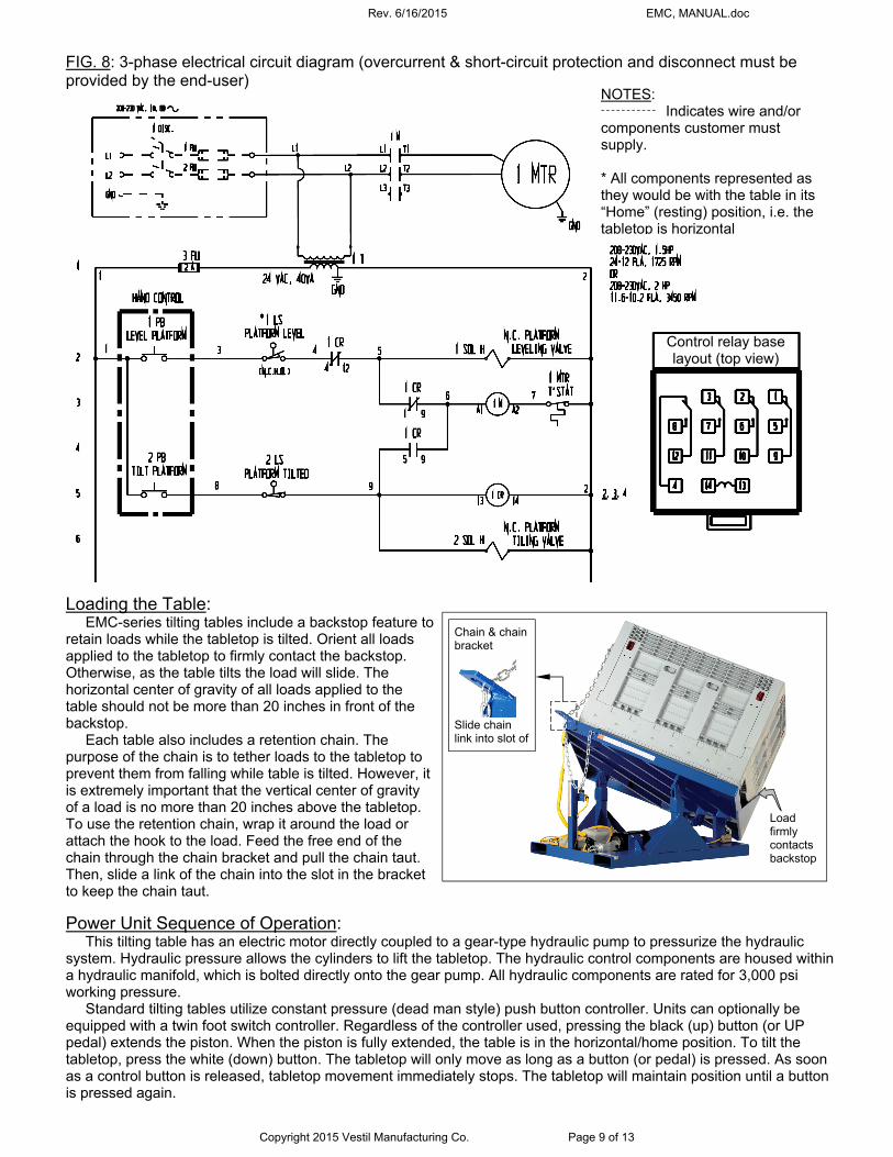
FIG. 8: 3-phase electrical circuit diagram (overcurrent & short-circuit protection and disconnect must be provided by the end-user) Loading the Table:
EMC-series tilting tables include a backstop feature to retain loads while the tabletop is tilted. Orient all loads applied to the tabletop to firmly contact the backstop. Otherwise, as the table tilts the load will slide. The horizontal center of gravity of all loads applied to the table should not be more than 20 inches in front of the backstop.
Each table also includes a retention chain. The purpose of the chain is to tether loads to the tabletop to prevent them from falling while table is tilted. However, it is extremely important that the vertical center of gravity of a load is no more than 20 inches above the tabletop. To use the retention chain, wrap it around the load or attach the hook to the load. Feed the free end of the chain through the chain bracket and pull the chain taut. Then, slide a link of the chain into the slot in the bracket to keep the chain taut.
Power Unit Sequence of Operation: This tilting table has an electric motor directly coupled to a gear-type hydraulic pump to pressurize the hydraulic
system. Hydraulic pressure allows the cylinders to lift the tabletop. The hydraulic control components are housed within a hydraulic manifold, which is bolted directly onto the gear pump. All hydraulic components are rated for 3,000 psi working pressure.
Standard tilting tables utilize constant pressure (dead man style) push button controller. Units can optionally be equipped with a twin foot switch controller. Regardless of the controller used, pressing the black (up) button (or UP pedal) extends the piston. When the piston is fully extended, the table is in the horizontal/home position. To tilt the tabletop, press the white (down) button. The tabletop will only move as long as a button (or pedal) is pressed. As soon as a control button is released, tabletop movement immediately stops. The tabletop will maintain position until a button is pressed again.
Control relay base layout (top view)
NOTES: Indicates wire and/or components customer must supply. * All components represented as they would be with the table in its “Home” (resting) position, i.e. the tabletop is horizontal
Load firmly contacts backstop
Chain & chain bracket
Slide chain link into slot of
Rev. 6/16/2015 EMC, MANUAL.doc
Copyright 2015 Vestil Manufacturing Co. Page 10 of 13
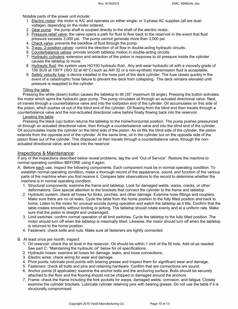
Notable parts of the power unit include: 1. Electric motor: the motor is A/C and operates on either single- or 3-phase AC supplies (all are dual-
voltage), depending on the motor ordered. 2. Gear pump: the pump shaft is coupled directly to the shaft of the electric motor. 3. Pressure relief valve: the valve opens a path for fluid to flow back to the reservoir in the event that fluid
pressure exceeds 3,000 psi. The pump cannot generate more than 3,000 psi. 4. Check valve: prevents the backflow of fluid through the pump. 5. 3-way, 2-position valves: control the direction of oil flow in double-acting hydraulic circuits. 6. Counterbalance valves: provide smooth tabletop motion in double-acting circuits. 7. Hydraulic cylinders: extension and retraction of the piston in response to oil pressure inside the cylinder
causes the tabletop to move. 8. Hydraulic fluid: the system uses HO150 hydraulic fluid. Any anti-wear hydraulic oil with a viscosity grade of
150 SUS at 100°F (ISO 32 at 40°C) such as AW 32 or a non-synthetic transmission fluid is acceptable. 9. Safety velocity fuse: a device installed in the hose port of the deck cylinder. The fuse closes quickly in the
event of a catastrophic hose failure to prevent the deck from collapsing. The deck remains elevated until pressure is reapplied to the cylinder.
Tilting the table: Pressing the white (down) button causes the tabletop to tilt (30° maximum tilt angle). Pressing the button activates
the motor which spins the hydraulic gear pump. The pump circulates oil through an actuated directional valve. Next, oil travels through a counterbalance valve and into the rod/piston end of the cylinder. Oil accumulates on this side of the piston, which pushes oil out of the blind end of the cylinder. Oil flowing from the blind end then travels through a counterbalance valve and the non-actuated directional valve before finally flowing back into the reservoir.
Leveling the table: Pressing the black (up) button returns the tabletop to the home/horizontal position. The pump pushes pressurized
oil through an actuated directional valve, then through a counterbalance valve and into the blind end of the cylinder. Oil accumulates inside the cylinder on the blind side of the piston. As oil fills the blind side of the cylinder, the piston extends from the opposite end of the cylinder. At the same time, oil in the cylinder but on the opposite side of the piston flows out of the cylinder. This displaced oil then travels through a counterbalance valve, through the non-actuated directional valve, and back into the reservoir. Inspections & Maintenance: If any of the inspections described below reveal problems, tag the unit “Out of Service”. Restore the machine to normal operating condition BEFORE using it again.
A. Before each use, inspect the following components. Each component must be in normal operating condition. To establish normal operating condition, make a thorough record of the appearance, sound, and function of the various parts of the machine when you first receive it. Compare later observations to the record to determine whether the machine is in normal operating condition. 1. Structural components: examine the frame and tabletop. Look for damaged welds, warps, cracks, or other
deformations. Give special attention to the brackets that connect the cylinder to the frame and tabletop. 2. Hydraulic system: check all hoses for kinks, pinches, and other damage. Examine hose fittings and couplers.
Make sure there are no oil leaks. Cycle the table from the home position to the fully tilted position and back to home. Listen to the motor for unusual sounds during operation and watch the tabletop as it tilts. Confirm that the table rotates smoothly without binding or jerking. The tabletop should rotate evenly and at a uniform rate. Make sure that the piston is straight and undamaged.
3. Limit switches: confirm normal operation of all limit switches. Cycle the tabletop to the fully tilted position. The motor should turn off when the tabletop is maximally tilted. Likewise, the motor should turn off when the tabletop is returned to the home position.
4. Fasteners: check bolts and nuts. Make sure all fasteners are tightly connected. B. At least once per month, inspect:
1. Oil reservoir: check the oil level in the reservoir. Oil should be within 1 inch of the fill hole. Add oil as needed. See part C: “Maintaining the hydraulic oil” below for oil specifications.
2. Hydraulic hoses: examine all hoses for damage, leaks, and loose connections. 3. Electric wires: check wiring for wear and damage. 4. Pivot points: lubricate pivot points with bearing grease and inspect them for significant wear and damage. 5. Fasteners: check all bolts and pins and retaining hardware. Confirm that are connections are sound. 6. Anchor points (if applicable): examine the anchor bolts and the anchoring surface. Bolts should be securely
attached to the floor and the flooring should not be chipped or damaged around the anchors. 7. Frame: check the frame including the fork pockets for warps, damaged welds, corrosion, and fatigue. Closely
examine the cylinder brackets. Lubricate cylinder retaining pins with bearing grease. Do not use the table if it is structurally compromised.
Rev. 6/16/2015 EMC, MANUAL.doc
Copyright 2015 Vestil Manufacturing Co. Page 11 of 13
8. Motor & pump: cycle the tabletop to the fully tilted position and back to the home position. Listen for unusual sounds as the tabletop cycles. Watch the tabletop to confirm that it tilts smoothly and at a uniform rate.
9. Labels: examine the labels (see “Labeling diagram” on p. 12). Each label shown in the diagram should be undamaged and readable. Replace any label that is damaged or missing.
C. Maintaining the hydraulic oil:
Change the oil if it has a milky appearance (indicating the presence of water) darkens, or becomes gritty. Only use anti-wear hydraulic oil of viscosity grade 150 SUS at 100°F (ISO 32 at 40°C), such as AW 32 or HO 150 or a non-synthetic transmission fluid. Synthetic transmission fluid can be used, but only after slushing the hydraulic system with the synthetic fluid before filling the reservoir. The reservoir is full when the surface of the oil is within 1 inch of the fill hole.
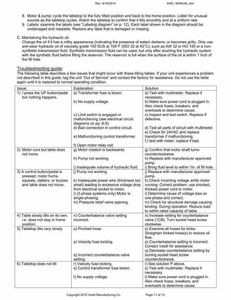
Troubleshooting guide: The following table describes a few issues that might occur with these tilting tables. If your unit experiences a problem not described in this guide, tag the unit “Out of Service” and contact the factory for assistance. Do not use the table again until it is restored to normal operating condition.
Issue: Explanation Solution 1) I press the UP button/pedal
but nothing happens. a) Transformer fuse is blown. b) No supply voltage. c) Limit switch is engaged or malfunctioning (see electrical circuit diagrams on pp. 8-9). d) Bad connection in control circuit. e) Malfunctioning control transformer. f) Open motor relay coil.
a) Test with multimeter. Replace if necessary. b) Make sure power cord is plugged in. Also check fuses, breakers, and overloads to determine cause. c) Inspect and test switch. Replace if defective. d) Test all parts of circuit with multimeter. e) Check for 24VAC and replace transformer if malfunctioning. f.) test with meter, replace if bad.
2) Motor runs but table does not move.
g) Motor rotation is backwards. h) Pump not working. i) Inadequate volume of hydraulic fluid.
g) Confirm that motor shaft turns counterclockwise. h) Replace with manufacturer approved pump. i) Bring fluid level to within 1in. of fill hole.
3) A control button/pedal is pressed, motor hums, squeals, clatters, or buzzes and table does not move.
j) Pump not working k) Inadequate power wire (thickness too small) leading to excessive voltage drop from electrical socket to motor. l) (3-phase systems only) Motor is single-phasing. m) Pressure relief valve opening.
j) Replace with manufacturer approved pump. k) Check incoming voltage while motor running. Correct problem: use shortest, thickest power cord to motor. l) Determine cause of voltage loss on one phase and correct. m) Check for structural damage causing binding. During operation. Reduce load to within rated capacity of table.
4) Table slowly tilts on its own, i.e. does not stay in home position.
n) Counterbalance valve setting incorrect.
n) Increase setting for counterbalance valve (1CB). Turn socket head screw clockwise.
5) Tabletop tilts very slowly o) Pinched hose. p) Velocity fuse locking. q) Incorrect counterbalance valve setting.
o) Examine all hoses for kinks. Straighten kinked hose(s) to restore oil flow. p) Counterbalance setting is incorrect. Contact Vestil for assistance. q) Decrease counterbalance setting by turning socket head screw counterclockwise.
6) Tabletop does not tilt r) Velocity fuse locking. s) Control transformer fuse blown. t) No supply voltage.
r) See solution P above. s) Test with multimeter. Replace if necessary. t) Make sure power cord is plugged in. Also check fuses, breakers, and overloads to determine cause.
Rev. 6/16/2015 EMC, MANUAL.doc
Copyright 2015 Vestil Manufacturing Co. Page 12 of 13
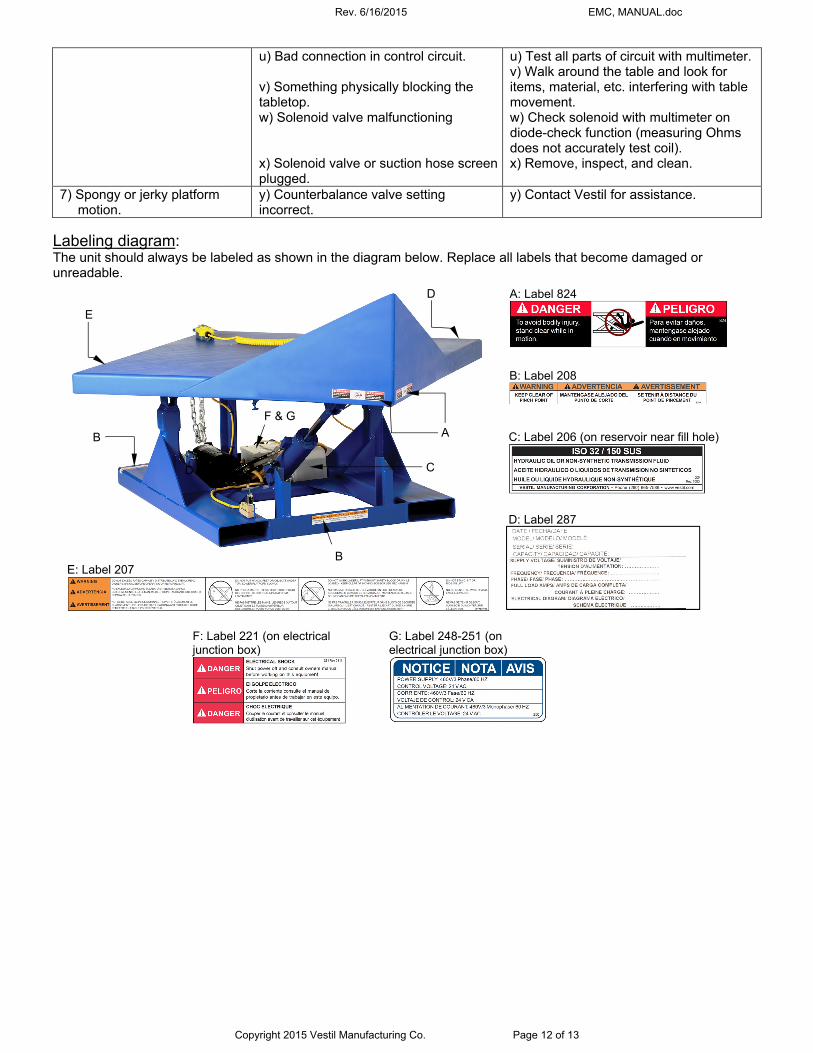
u) Bad connection in control circuit. v) Something physically blocking the tabletop. w) Solenoid valve malfunctioning x) Solenoid valve or suction hose screen plugged.
u) Test all parts of circuit with multimeter. v) Walk around the table and look for items, material, etc. interfering with table movement. w) Check solenoid with multimeter on diode-check function (measuring Ohms does not accurately test coil). x) Remove, inspect, and clean.
7) Spongy or jerky platform motion.
y) Counterbalance valve setting incorrect.
y) Contact Vestil for assistance.
C
A B
D
E
D A: Label 824
C: Label 206 (on reservoir near fill hole)
B: Label 208
D: Label 287
G: Label 248-251 (on electrical junction box)
E: Label 207
Labeling diagram: The unit should always be labeled as shown in the diagram below. Replace all labels that become damaged or unreadable.
B
F & G
F: Label 221 (on electrical junction box)
Rev. 6/16/2015 EMC, MANUAL.doc
Copyright 2015 Vestil Manufacturing Co. Page 13 of 13
LIMITED WARRANTY
Vestil Manufacturing Corporation (“Vestil”) warrants this product to be free of defects in material and workmanship during the warranty period. Our warranty obligation is to provide a replacement for a defective original part if the part is covered by the warranty, after we receive a proper request from the warrantee (you) for warranty service.
Who may request service? Only a warrantee may request service. You are a warrantee if you purchased the product from Vestil or from an authorized distributor AND Vestil has been fully paid.
What is an “original part”? An original part is a part used to make the product as shipped to the warrantee.
What is a “proper request”? A request for warranty service is proper if Vestil receives: 1) a photocopy of the Customer Invoice that displays the shipping date; AND 2) a written request for warranty service including your name and phone number. Send requests by any of the following methods:
Mail Fax Email Vestil Manufacturing Corporation (260) 665-1339 [email protected] 2999 North Wayne Street, PO Box 507 Phone Angola, IN 46703 (260) 665-7586
In the written request, list the parts believed to be defective and include the address where replacements should be delivered.
What is covered under the warranty? After Vestil receives your request for warranty service, an authorized representative will contact you to determine whether your claim is covered by the warranty. Before providing warranty service, Vestil may require you to send the entire product, or just the defective part or parts, to its facility in Angola, IN. The warranty covers defects in the following original dynamic components: motors, hydraulic pumps, electronic controllers, switches and cylinders. It also covers defects in original parts that wear under normal usage conditions (“wearing parts”), such as bearings, hoses, wheels, seals, brushes, and batteries.
How long is the warranty period? The warranty period for original dynamic components is 1 year. For wearing parts, the warranty period is 90 days. The warranty periods begin on the date when Vestil ships the product to the warrantee. If the product was purchased from an authorized distributor, the periods begin when the distributor ships the product. Vestil may, at its sole discretion, extend the warranty periods for products shipped from authorized distributors by up to 30 days to account for shipping time.
If a defective part is covered by the warranty, what will Vestil do to correct the problem? Vestil will provide an appropriate replacement for any covered part. An authorized representative of Vestil will contact you to discuss your claim.
What is not covered by the warranty? 1. Labor; 2. Freight; 3. Occurrence of any of the following, which automatically voids the warranty:
Product misuse; Negligent operation or repair; Corrosion or use in corrosive environments; Inadequate or improper maintenance; Damage sustained during shipping; Collisions or other incidental contacts causing damage to the product; Unauthorized modifications: DO NOT modify the product IN ANY WAY without first receiving written
authorization from Vestil. Modification(s) might make the product unsafe to use or might cause excessive and/or abnormal wear.
Do any other warranties apply to the product? Vestil Manufacturing Corp. makes no other express warranties. All implied warranties are disclaimed to the extent allowed by law. Any implied warranty not disclaimed is limited in scope to the terms of this Limited Warranty.