emc test reportfaenl.msi.com/ftp/ce documents/notebook/ms-1736x... · page 5 of 124 audix...
TRANSCRIPT


Page 1 of 124
Audix Technology (Wujiang) Co., Ltd. EMC Dept. Report No.: ACWE-E0911006
EMC TEST REPORT For
Micro-Star Int'L Co., Ltd. Notebook PC
Model No.: MS-1736 Marketing Name: CR720
Brand: msi
Prepared for
Micro-Star Int'L Co., Ltd. No.69, Li-De St., Chung-Ho City, Taipei Hsien, Taiwan
Prepared by
Audix Technology (Wujiang) Co., Ltd. EMC Dept. No.1289 Jiangxing East Road, the Eastern Part of Wujiang Economic Development Zone
Jiangsu China 215200
Tel.: +86-512-63403993 Fax : +86-512-63403339
Report Number : ACWE-E0911006 Date of Test : Nov.04~Nov.07, 2009 Date of Report : Nov.11, 2009

Page 2 of 124
Audix Technology (Wujiang) Co., Ltd. EMC Dept. Report No.: ACWE-E0911006
TABLE OF CONTENTS Description Page TEST REPORT VERIFICATION.......................................................................................................4 1 SUMMARY OF STANDARDS AND RESULTS.......................................................................5
1.1 Description of Standards and Results..................................................................................................5 1.2 Description of Performance Criteria....................................................................................................6
2 GENERAL INFORMATION ......................................................................................................7 2.1 Description of Device (EUT) ..............................................................................................................7 2.2 EUT’s Configuration under Test .........................................................................................................7 2.3 Operating Condition of EUT .............................................................................................................15 2.4 Tested Supporting System Details.....................................................................................................15 2.5 Description of Test Facility ...............................................................................................................18 2.6 Measurement Uncertainty .................................................................................................................18
3 CONDUCTED DISTURBANCE MEASUREMENT ..............................................................19 3.1 Test Equipment..................................................................................................................................19 3.2 Block Diagram of Test Setup for AC Mains Port .............................................................................19 3.3 Block Diagram of Test Setup for RJ45 Port......................................................................................20 3.4 Limits for Conducted Disturbance Voltage (EN 55022, Class B).....................................................20 3.5 Test Procedure ...................................................................................................................................21 3.6 Measurement Results.........................................................................................................................22
4 RADIATED DISTURBANCE MEASUREMENT ..................................................................45 4.1 Test Equipment..................................................................................................................................45 4.2 Block Diagram of Test Setup ............................................................................................................46 4.3 Limits for Radiated Disturbance (30MHz~1000MHz) (EN 55022, Class B) ...................................47 4.4 Limits for Radiated Disturbance (1GHz~6GHz) (EN55022, Class B) .............................................48 4.5 Test Procedure ...................................................................................................................................48 4.6 Measurement Results.........................................................................................................................49
5 POWER HARMONICS AND FLICKER MEASUREMENT................................................59 5.1 Test Equipment..................................................................................................................................59 5.2 Block Diagram of Test Setup ............................................................................................................59 5.3 Test Standard .....................................................................................................................................59 5.4 Test Procedure ...................................................................................................................................59 5.5 Test Results .......................................................................................................................................60
6 ELECTROSTATIC DISCHARGE IMMUNITY TEST.........................................................77 6.1 Test Equipment..................................................................................................................................77 6.2 Block Diagram of Test Setup ............................................................................................................77 6.3 Test Standard .....................................................................................................................................77 6.4 Severity Levels and Performance Criterion.......................................................................................77 6.5 Test Procedure ...................................................................................................................................78 6.6 Test Results .......................................................................................................................................78
7 RF FIELD STRENGTH IMMUNITY TEST...........................................................................84 7.1 Test Equipment..................................................................................................................................84 7.2 Block Diagram of Test Setup ............................................................................................................84 7.3 Test Standard .....................................................................................................................................85 7.4 Severity Levels and Performance Criterion.......................................................................................85 7.5 Test Procedure ...................................................................................................................................85 7.6 Test Results .......................................................................................................................................86
8 ELECTRICAL FAST TRANSIENT/BURST IMMUNITY TEST ........................................89 8.1 Test Equipment..................................................................................................................................89 8.2 Block Diagram of Test Setup ............................................................................................................89 8.3 Test Standard .....................................................................................................................................89 8.4 Severity Levels and Performance Criterion.......................................................................................89 8.5 Test Procedure ...................................................................................................................................90 8.6 Test Results .......................................................................................................................................90

Page 3 of 124
Audix Technology (Wujiang) Co., Ltd. EMC Dept. Report No.: ACWE-E0911006
9 SURGE IMMUNITY TEST.......................................................................................................93 9.1 Test Equipment..................................................................................................................................93 9.2 Block Diagram of Test Setup ............................................................................................................93 9.3 Test Standard .....................................................................................................................................93 9.4 Severity Levels and Performance Criterion.......................................................................................93 9.5 Test Procedure ...................................................................................................................................94 9.6 Test Results .......................................................................................................................................94
10 CONDUCTED DISTURBANCE IMMUNITY TEST.............................................................99 10.1 Test Equipment..................................................................................................................................99 10.2 Block Diagram of Test Setup ............................................................................................................99 10.3 Test Standard .....................................................................................................................................99 10.4 Severity Levels and Performance Criterion.....................................................................................100 10.5 Test Procedure .................................................................................................................................100 10.6 Test Results .....................................................................................................................................101
11 POWER FREQUENCY MAGNETIC FIELD IMMUNITY TEST .......................................104 11.1 Test Equipment................................................................................................................................104 11.2 Block Diagram of Test Setup ..........................................................................................................104 11.3 Test Standard ...................................................................................................................................104 11.4 Severity Levels and Performance Criterion.....................................................................................104 11.5 Test Procedure .................................................................................................................................105 11.6 Test Results .....................................................................................................................................105
12 VOLTAGE DIPS AND INTERRUPTIONS IMMUNITY TEST.........................................108 12.1 Test Equipment................................................................................................................................108 12.2 Block Diagram of Test Setup ..........................................................................................................108 12.3 Test Standard ...................................................................................................................................108 12.4 Severity Levels and Performance Criterion.....................................................................................108 12.5 Test Procedure .................................................................................................................................109 12.6 Test Results .....................................................................................................................................109
13 PHOTOGRAPHS......................................................................................................................112 13.1 Photos of Conducted Disturbance Measurement.............................................................................112 13.2 Photos of Radiated Disturbance Measurement................................................................................114 13.3 Photos of Harmonic & Flicker Measurement..................................................................................117 13.4 Photos of Electrostatic Discharge Immunity Test ...........................................................................117 13.5 Photos of RF Field Strength Immunity Test....................................................................................118 13.6 Photos of Electrical Fast Transient/Burst Immunity Test................................................................119 13.7 Photos of Surge Immunity Test .......................................................................................................120 13.8 Photos of Conducted Disturbance Immunity Test...........................................................................121 13.9 Photos of Power Frequency Magnetic Field Immunity Test ...........................................................122 13.10 Photos of Voltage Dips and Interruptions Immunity Test...............................................................123 13.11 Photos of host PC for RJ45 ping test...............................................................................................123 13.12 Photos of WALAN& Bluetooth function test .................................................................................124
APPENDIX I Pre-scan data of radiated disturbance measurement APPENDIX II Photos of EUT


Page 5 of 124
Audix Technology (Wujiang) Co., Ltd. EMC Dept. Report No.: ACWE-E0911006
1 SUMMARY OF STANDARDS AND RESULTS
1.1 Description of Standards and Results The EUT have been tested according to the applicable standards as referenced below.
EMISSION
Description of Test Item Standard Limits Results Conducted disturbance
at main terminal EN 55022/2006+A1/2007 Class B PASS
Conducted common mode disturbance at
telecommunication port EN 55022/2006+A1/2007 Class B PASS
Radiated disturbance EN 55022/2006+A1/2007 Class B PASS
Harmonic current emissions
EN 61000-3-2/2006
Class D PASS
Voltage fluctuations & flicker
EN 61000-3-3/1995 + A1/2001+A2/2005
Pst=1 dc(%)=3.3%
dMax.(%)=4% d(t)>3.3%=500ms
PASS
IMMUNITY (EN55024/ 1998 + A1/2001 + A2/2003)
Description of Test Item Basic Standard Performance Criteria Results
Electrostatic discharge (ESD) IEC 61000-4-2/2008 B PASS
Radio-frequency, Continuous radiated
disturbance IEC 61000-4-3/2008 A PASS
Electrical fast transient (EFT)
IEC 61000-4-4/2004+Corr.1/2006 +Corr.2/2007 B PASS
Surge IEC 61000-4-5/2005 B PASS Radio-frequency,
Continuous conducted disturbance
IEC 61000-4-6/2008 A PASS
Power frequency magnetic field IEC 61000-4-8/2001 A PASS
Voltage dips, >95% reduction B PASS
Voltage dips, 30% reduction C PASS
Voltage interruptions
IEC 61000-4-11/2004
C PASS

Page 6 of 124
Audix Technology (Wujiang) Co., Ltd. EMC Dept. Report No.: ACWE-E0911006
1.2 Description of Performance Criteria
General Performance Criteria Examples of functions defined by the manufacturer to be evaluated during testing include, but are not limited to, the following:
essential operational modes and states; tests of all peripheral access (hard disks, floppy disks, printers, keyboard, mouse, etc.); quality of software execution; quality of data display and transmission; quality of speech transmission.
1.2.1 Performance criterion A
The equipment shall continue to operate as intended without operator intervention. No degradation of performance or loss of function is allowed below a performance level specified by the manufacture when the equipment is used as intended. The performance level may be replaced by a permissible loss of performance. If the minimum performance level or the permissible performance loss is not specified by the manufacturer, then either of these may be deriver from the product description and documentation, and by what the user may reasonably expect from the equipment if used as intended.
1.2.2 Performance criterion B
After the test, the equipment shall continue to operate as intended without operator intervention. No degradation of performance or loss of function is allowed, after the application of the phenomena below a performance level specified by the manufacture, when the equipment is used as intended. The performance level may be replaced by a permissible loss of performance. During the test, degradation of performance is allowed. However, no change of operation state or stored data is allowed to persist after the test. If the minimum performance level (or the permissible performance loss) is not specified by the manufacturer, then either of these may be deriver from the product description and documentation, and by what the user may reasonably expect from the equipment if used as intended.
1.2.3 Performance criterion C
Loss of function is allowed, provided the function is self-recoverable, or can be restored by the operation of the controls by the user in accordance with the manufacture’s instructions. Functions, and/or information stored in non-volatile memory, or protected by a battery backup, shall not be loss.
Page 7 of 124
Audix Technology (Wujiang) Co., Ltd. EMC Dept. Report No.: ACWE-E0911006
2 GENERAL INFORMATION
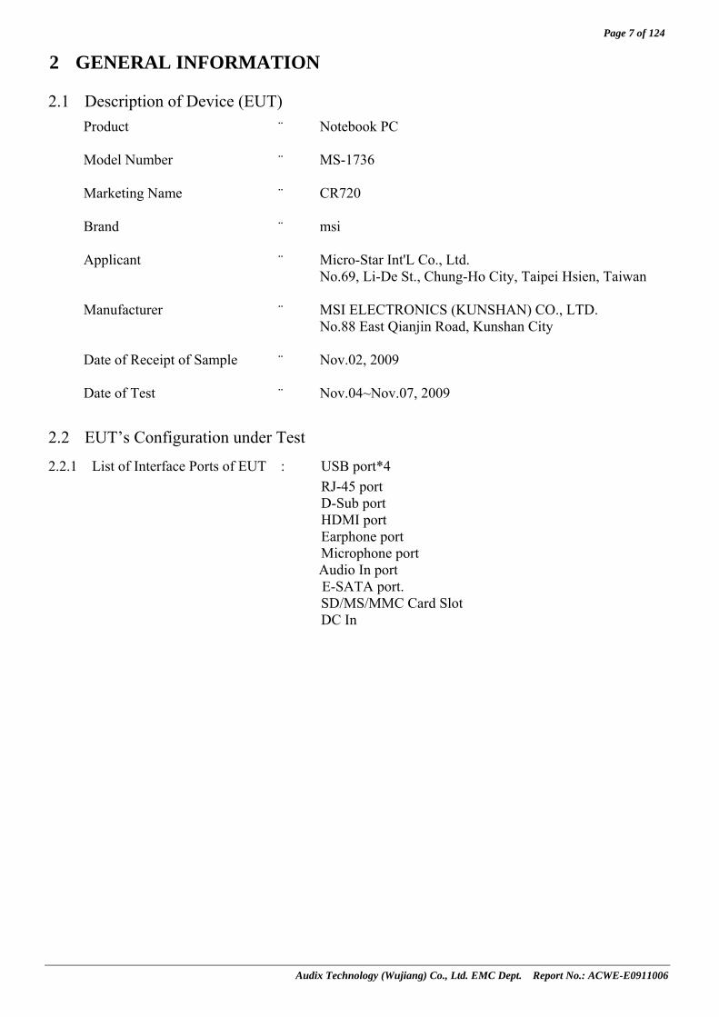
2.1 Description of Device (EUT) Product : Notebook PC
Model Number : MS-1736
Marketing Name : CR720
Brand : msi
Applicant : Micro-Star Int'L Co., Ltd.
No.69, Li-De St., Chung-Ho City, Taipei Hsien, Taiwan
Manufacturer : MSI ELECTRONICS (KUNSHAN) CO., LTD. No.88 East Qianjin Road, Kunshan City
Date of Receipt of Sample : Nov.02, 2009
Date of Test : Nov.04~Nov.07, 2009
2.2 EUT’s Configuration under Test
2.2.1 List of Interface Ports of EUT : USB port*4 RJ-45 port D-Sub port HDMI port Earphone port Microphone port Audio In port E-SATA port. SD/MS/MMC Card Slot DC In
Page 8 of 124
Audix Technology (Wujiang) Co., Ltd. EMC Dept. Report No.: ACWE-E0911006
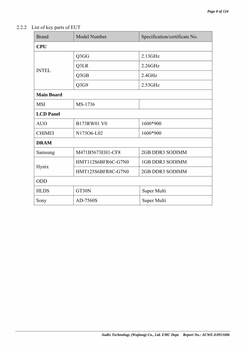
2.2.2 List of key parts of EUT
Brand Model Number Specification/certificate No.
CPU
Q3GG 2.13GHz
Q3LR 2.26GHz
Q3GB 2.4GHz INTEL
Q3G9 2.53GHz
Main Board
MSI MS-1736
LCD Panel
AUO B173RW01 V0 1600*900
CHIMEI N173O6-L02 1600*900
DRAM
Samsung M471B5673EH1-CF8 2GB DDR3 SODIMM
HMT112S6BFR6C-G7N0 1GB DDR3 SODIMM Hynix
HMT125S6BFR8C-G7N0 2GB DDR3 SODIMM
ODD
HLDS GT30N Super Multi
Sony AD-7560S Super Multi
Page 9 of 124
Audix Technology (Wujiang) Co., Ltd. EMC Dept. Report No.: ACWE-E0911006
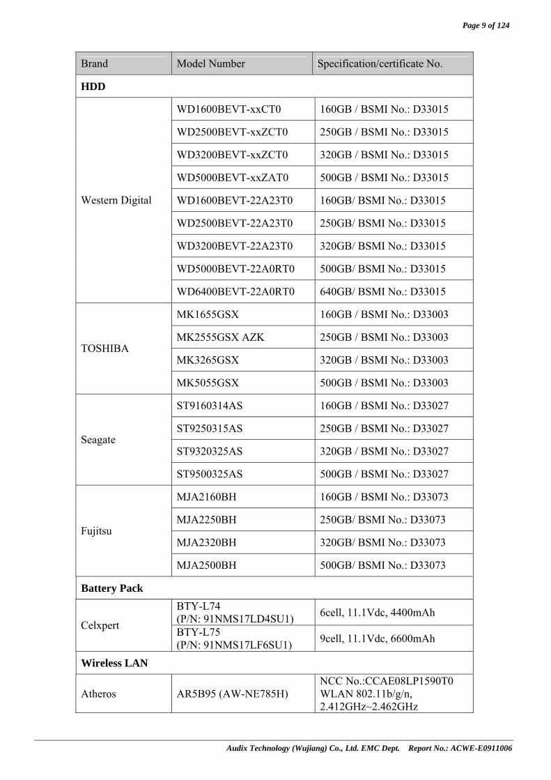
Brand Model Number Specification/certificate No.
HDD
WD1600BEVT-xxCT0 160GB / BSMI No.: D33015
WD2500BEVT-xxZCT0 250GB / BSMI No.: D33015
WD3200BEVT-xxZCT0 320GB / BSMI No.: D33015
WD5000BEVT-xxZAT0 500GB / BSMI No.: D33015
WD1600BEVT-22A23T0 160GB/ BSMI No.: D33015
WD2500BEVT-22A23T0 250GB/ BSMI No.: D33015
WD3200BEVT-22A23T0 320GB/ BSMI No.: D33015
WD5000BEVT-22A0RT0 500GB/ BSMI No.: D33015
Western Digital
WD6400BEVT-22A0RT0 640GB/ BSMI No.: D33015
MK1655GSX 160GB / BSMI No.: D33003
MK2555GSX AZK 250GB / BSMI No.: D33003
MK3265GSX 320GB / BSMI No.: D33003 TOSHIBA
MK5055GSX 500GB / BSMI No.: D33003
ST9160314AS 160GB / BSMI No.: D33027
ST9250315AS 250GB / BSMI No.: D33027
ST9320325AS 320GB / BSMI No.: D33027 Seagate
ST9500325AS 500GB / BSMI No.: D33027
MJA2160BH 160GB / BSMI No.: D33073
MJA2250BH 250GB/ BSMI No.: D33073
MJA2320BH 320GB/ BSMI No.: D33073 Fujitsu
MJA2500BH 500GB/ BSMI No.: D33073
Battery Pack BTY-L74 (P/N: 91NMS17LD4SU1) 6cell, 11.1Vdc, 4400mAh
Celxpert BTY-L75 (P/N: 91NMS17LF6SU1) 9cell, 11.1Vdc, 6600mAh
Wireless LAN
Atheros AR5B95 (AW-NE785H) NCC No.:CCAE08LP1590T0 WLAN 802.11b/g/n, 2.412GHz~2.462GHz

Page 10 of 124
Audix Technology (Wujiang) Co., Ltd. EMC Dept. Report No.: ACWE-E0911006
Brand Model Number Specification/certificate No.
Bluetooth Module
msi MS-3870 (Wireless 802.11b/g/n 1T1R+BT2.1 EDR combo slim module)
CSR BSMAN1(MS-3801) 2.402GHz~2.48GHz NCC No.:CCAE09LP0840T0
Touch Pad
SYNAPTICS TM-00300-000 (S78-3700360-SD2) 79.7mm*47.7mm
SENTELIC TPA2D21C99 (S78-3700360-SK9) 79.7mm*47.7mm
Keyboard
Sunrex V111922AK1
WEBCAM
Bison BN29M6SSB-010 1.3M Pixels
AZUREWAVE AM-1C027 1.3M Pixels
AC Adapter
DELTA ADP-65HB BB
I/P:100-240V, 1.5A, O/P: 19Vdc, 3.42A BSMI No.: R33030 DC Cord: Unshielded, Undetachable, 1.8m, 1
ferrite core
LITEON PA-1650-68
I/P:100-240V, 50-60Hz, 2.0A, O/P: 19Vdc, 3.42A BSMI No.: R33275 DC Cord: Unshielded, Undetachable, 1.8m, 1
ferrite core
AC Power
lsheng CIONN-3P Unshielded, Detachable, 1.8m
Page 11 of 124
Audix Technology (Wujiang) Co., Ltd. EMC Dept. Report No.: ACWE-E0911006
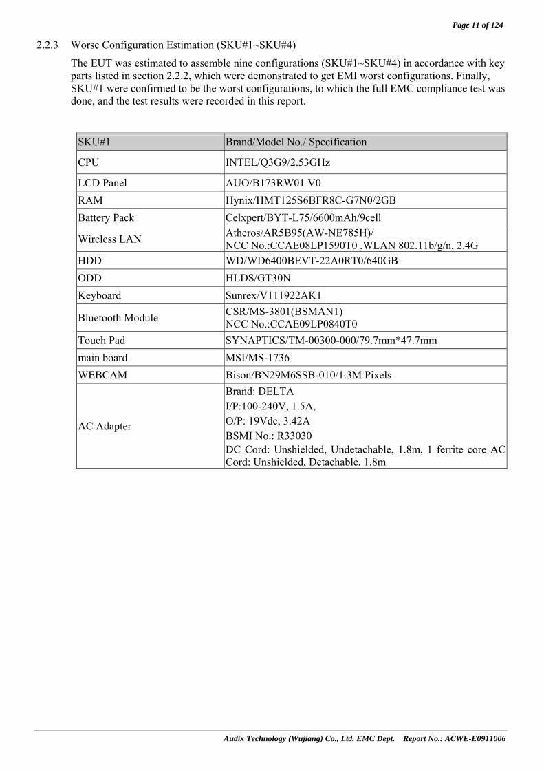
2.2.3 Worse Configuration Estimation (SKU#1~SKU#4)
The EUT was estimated to assemble nine configurations (SKU#1~SKU#4) in accordance with key parts listed in section 2.2.2, which were demonstrated to get EMI worst configurations. Finally, SKU#1 were confirmed to be the worst configurations, to which the full EMC compliance test was done, and the test results were recorded in this report.
SKU#1 Brand/Model No./ Specification
CPU INTEL/Q3G9/2.53GHz
LCD Panel AUO/B173RW01 V0 RAM Hynix/HMT125S6BFR8C-G7N0/2GB Battery Pack Celxpert/BYT-L75/6600mAh/9cell
Wireless LAN Atheros/AR5B95(AW-NE785H)/ NCC No.:CCAE08LP1590T0 ,WLAN 802.11b/g/n, 2.4G
HDD WD/WD6400BEVT-22A0RT0/640GB ODD HLDS/GT30N Keyboard Sunrex/V111922AK1
Bluetooth Module CSR/MS-3801(BSMAN1) NCC No.:CCAE09LP0840T0
Touch Pad SYNAPTICS/TM-00300-000/79.7mm*47.7mm main board MSI/MS-1736 WEBCAM Bison/BN29M6SSB-010/1.3M Pixels
AC Adapter
Brand: DELTA I/P:100-240V, 1.5A, O/P: 19Vdc, 3.42A BSMI No.: R33030 DC Cord: Unshielded, Undetachable, 1.8m, 1 ferrite core AC Cord: Unshielded, Detachable, 1.8m

Page 12 of 124
Audix Technology (Wujiang) Co., Ltd. EMC Dept. Report No.: ACWE-E0911006
SKU#2 Brand/Model No./ Specification
CPU INTEL/Q3GB/2.4GHz
LCD Panel AUO/B173RW01 V0 RAM Samsung/M471B5673EH1-CF8/2GB Battery Pack Celxpert/BYT-L75/6600mAh/9cell
Wireless LAN Atheros/AR5B95(AW-NE785H)/ NCC No.:CCAE08LP1590T0 ,WLAN 802.11b/g/n, 2.4G
HDD TOSHIBA/MK5055GSX/500GB ODD Sony/AD-7560S Keyboard Sunrex/V111922AK1
Bluetooth Module CSR/MS-3801(BSMAN1) NCC No.:CCAE09LP0840T0
Touch Pad SYNAPTICS/TM-00300-000/79.7mm*47.7mm main board MSI/MS-1736 WEBCAM Bison/BN29M6SSB-010/1.3M Pixels
AC Adapter
Brand: DELTA I/P:100-240V, 1.5A, O/P: 19Vdc, 3.42A BSMI No.: R33030 DC Cord: Unshielded, Undetachable, 1.8m, 1 ferrite core AC Cord: Unshielded, Detachable, 1.8m

Page 13 of 124
Audix Technology (Wujiang) Co., Ltd. EMC Dept. Report No.: ACWE-E0911006
SKU#3 Brand/Model No./ Specification
CPU INTEL/Q3LR/2.26GHz
LCD Panel CHIMEI/N173O6-L02 RAM Hynix/HMT112S6BFR6C-G7N0/1GB Battery Pack Celxpert/BYT-L74/4400mAh/6cell
Wireless LAN Atheros/AR5B95(AW-NE785H)/ NCC No.:CCAE08LP1590T0 ,WLAN 802.11b/g/n, 2.4G
HDD Seagate/ST9500325AS/500GB ODD HLDS/GT30N Keyboard Sunrex/V111922AK1
Bluetooth Module msi/MS-3870
Touch Pad SENTELIC/TPA2D21C99/79.7mm*47.7mm main board MSI/MS-1736 WEBCAM AZUREWAVE/AM-1C027/1.3M Pixels
AC Adapter
Brand: LITEON I/P:100-240V, 50-60Hz, 2.0A, O/P: 19Vdc, 3.42A BSMI No.: R33275 DC Cord: Unshielded, Undetachable, 1.8m, 1 ferrite core AC Cord: Unshielded, Detachable, 1.8m

Page 14 of 124
Audix Technology (Wujiang) Co., Ltd. EMC Dept. Report No.: ACWE-E0911006
SKU#4 Brand/Model No./ Specification CPU INTEL/Q3GG/2.13GHz LCD Panel CHIMEI/N173O6-L02 RAM Samsung/M471B5673EH1-CF8/2GB Battery Pack Celxpert/BYT-L74/4400mAh/6cell
Wireless LAN Atheros/AR5B95(AW-NE785H)/ NCC No.:CCAE08LP1590T0 ,WLAN 802.11b/g/n, 2.4G
HDD Fujitsu/MJA2500BH/500GB ODD Sony/AD-7560S Keyboard Sunrex/V111922AK1 Bluetooth Module msi/MS-3870 Touch Pad SENTELIC/TPA2D21C99/79.7mm*47.7mm main board MSI/MS-1736 WEBCAM AZUREWAVE/AM-1C027/1.3M Pixels
AC Adapter
Brand: LITEON I/P:100-240V, 50-60Hz, 2.0A, O/P: 19Vdc, 3.42A BSMI No.: R33275 DC Cord: Unshielded, Undetachable, 1.8m, 1 ferrite core AC Cord: Unshielded, Detachable, 1.8m

Page 15 of 124
Audix Technology (Wujiang) Co., Ltd. EMC Dept. Report No.: ACWE-E0911006
2.3 Operating Condition of EUT
EUT Exercise Program and Condition Operating System Windows 7 Test Program EMC test.exe ; Media Player.exe ; Winthrax
Graphic controllerDisplay scrolling “H” pattern with test resolution 1600*900@60Hz
IDE controller Read/Write operation to USB HDD
Audio controller Play 1kHz audio signal LAN controller Data transfer to host PC
Wireless LAN Send Signal by WLAN software
Bluetooth Send data by Bluetooth software Webcam Operating normally
2.4 Tested Supporting System Details
2.4.1 LCD Monitor #1
Manufacturer : DELL Model Number : SP2309Wc Serial Number : CN-0U781F-64180-95V-002S BSMI ID : R33037 FCC ID : FCC By DoC D-Sub Cable : Shielded, Detachable, 1.8m, bonded 2 ferrite
cores Power Cord : Unshielded, Detachable, 3.0m
2.4.2 LCD Monitor #2
Manufacturer : DELL Model Number : S2409Wb Serial Number : CN-0W570D-74261-97G-2MAO FCC ID : FCC By DoC BSMI ID : R3A002 HDMI Cable : Shielded, Detachable, 1.8m Power Cord : Unshielded, Detachable, 2.0m
2.4.3 Earphone & Microphone
Manufacturer : SOMIC Model Number : SM-301 Data Cable : Unshielded, Undetachable, 2.2 m,
2.4.4 Microphone
Manufacturer : N/A Model Number : N/A Data Cable : Unshielded, Undetachable, 2.5m

Page 16 of 124
Audix Technology (Wujiang) Co., Ltd. EMC Dept. Report No.: ACWE-E0911006
2.4.5 Mouse
Manufacturer : DELL Model Number : MOC5UO Serial Number : 10S08R2F FCC ID : FCC By DoC BSMI ID : R41108 Data Cable : Shielded, Undetachable, 1.5m
2.4.6 HDD#1
Manufacturer : Seagate Model Number : FreeAgent Pro Serial Number : 9QM33930 FCC ID : FCC By DoC Data Cable : Shielded, Detachable, 1.0m
2.4.7 HDD#2
Manufacturer : Samsung Model Number : HM042HI Serial Number : S07WJ10L607269 FCC ID : FCC By DoC Data Cable : Shielded, Detachable, 1.0m
2.4.8 1394 HDD
Manufacturer : Seagate Model Number : Dual Firewire 400 Serial Number : 6QG0XYY1 FCC ID : FCC By DoC Data Cable : Shielded, Detachable, 1.0m Power Cable : Unshielded, Detachable, 2.0m
2.4.9 Printer
Manufacturer : HP Model Number : DESKJET3918 Serial Number : CN64R1N251 BSMI ID : R33001 USB Cable : Shielded, Detachable, 1.5m AC Adapter : HP/090-4397
I/P:100-240V, 50-60Hz, 500mA, O/P: +32Vdc, 500mA max +15Vdc, 530mA max BSMI No.: R33160 AC Cord: Unshielded,Detachable, 1.8m DC Cord: Unshielded, Undetachable, 1.8m, 1 ferrite core
2.4.10 Mini SD Card Adapter (2GB)
Manufacturer : A-DATA
Page 17 of 124
Audix Technology (Wujiang) Co., Ltd. EMC Dept. Report No.: ACWE-E0911006
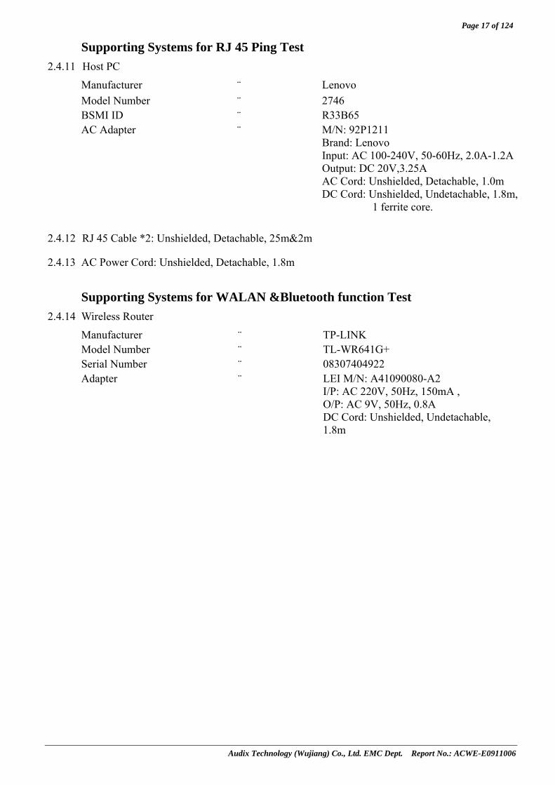
Supporting Systems for RJ 45 Ping Test
2.4.11 Host PC
Manufacturer : Lenovo Model Number : 2746 BSMI ID : R33B65 AC Adapter : M/N: 92P1211
Brand: Lenovo Input: AC 100-240V, 50-60Hz, 2.0A-1.2A Output: DC 20V,3.25A AC Cord: Unshielded, Detachable, 1.0m DC Cord: Unshielded, Undetachable, 1.8m,
1 ferrite core.
2.4.12 RJ 45 Cable *2: Unshielded, Detachable, 25m&2m
2.4.13 AC Power Cord: Unshielded, Detachable, 1.8m
Supporting Systems for WALAN &Bluetooth function Test
2.4.14 Wireless Router
Manufacturer : TP-LINKModel Number : TL-WR641G+ Serial Number : 08307404922 Adapter : LEI M/N: A41090080-A2
I/P: AC 220V, 50Hz, 150mA , O/P: AC 9V, 50Hz, 0.8A DC Cord: Unshielded, Undetachable, 1.8m

Page 18 of 124
Audix Technology (Wujiang) Co., Ltd. EMC Dept. Report No.: ACWE-E0911006
2.5 Description of Test Facility Name of Firm : Audix Technology (Wujiang) Co., Ltd. EMC Dept.
Site Location : No. 1289 Jiangxing East Road, the Eastern Part
of Wujiang Economic Development Zone Jiangsu China 215200
Test Facilities : No.1 10m semi-anechoic chamber
FCC filing on Aug.21, 2009 Registration No.: 252588 No. 1 conducted shielding enclosure
The Complex Immunity Test Room
RS&CS Test Room
NVLAP Lab Code : 200786-0 (NVLAP is a NATA accredited body under Mutual Recognition Agreement) Valid until on Sep.30, 2010
DAR-Registration No. : DAT-P-264/07-00 Valid until on Dec.15, 2012
2.6 Measurement Uncertainty
Test Item Uncertainty Conducted disturbance Measurement ± 2.75dB
± 3.06dB (Horizontal) Radiated disturbance Measurement (Distance: 10m) ± 3.22dB (Vertical)
Remark:Uncertainty = kuc(y)

Page 19 of 124
Audix Technology (Wujiang) Co., Ltd. EMC Dept. Report No.: ACWE-E0911006
3 CONDUCTED DISTURBANCE MEASUREMENT
3.1 Test Equipment
The following test equipment was used during the conducted emission measurement: 3.1.1 For AC Mains Port
Item Type Manufacturer Model No. Serial No. Last Cal. Next Cal. 1. Test Receiver R & S ESCI 100352 2009-01-07 2010-01-06 2. A.M.N R & S ESH2-Z5 100153 2009-03-25 2010-03-24 3. L.I.S.N. Kyoritsu KNW-407 8-1793-4 2009-08-11 2010-08-10 4. Pulse Limiter R&S ESH3-Z2 100605 2009-08-11 2010-08-10 5. 50Ω Coaxial Switch Anritsu MP59B 6200547934 2009-08-11 2010-08-10 6. 50ohm Terminator N/A N/A N/A 2009-03-25 2010-03-24
7. RF Cable Harbour Industries RG400 003 2009-08-14 2010-08-13
3.1.2 For Telecommunication Port Item Type Manufacturer Model No. Serial No. Last Cal. Next Cal.
1. Test Receiver R & S ESCI 100352 2009-01-07 2010-01-06 2. A.M.N R & S ESH2-Z5 100153 2009-03-25 2010-03-24 3. L.I.S.N. Kyoritsu KNW-407 8-1793-4 2009-08-11 2010-08-10
4. I.S.N. FCC FCC-TLISN-T4-02 20497 2009-08-11 2010-08-10
5. 50 ohm Terminator N/A N/A N/A 2009-03-25 2010-03-24 6. 50Ω Coaxial Switch ANRITSU MP59B 6200547934 2009-08-11 2010-08-10 7. Pulse Limiter R&S ESH3-Z2 100605 2009-08-11 2010-08-10
8. RF Cable Harbour Industries RG400 003 2009-08-11 2010-08-10
3.2 Block Diagram of Test Setup for AC Mains Port
AC POWER SOURCE
: POWER LINE: SIGNAL LINE
A.M.N.
LISN50 ohm Terminator
PERSONAL COMPUTER
TEST RECEIVER
PRINTER
PULSE LIMITER
COAXIAL SWITCH
Notebook PC (EUT)
LCD Monitor #1
Earphone & Microphone
Host PC Printer
: FERRITE CORE
LCD Monitor #2
RJ45 USB D-Sub HDMI
HDD*2
: AC Adapter
AC POWER SOURCE
Mouse
1394 HDD
Wireless Router
Test supporting system for WLAN and Bluetooth function test
Microphone

Page 20 of 124
Audix Technology (Wujiang) Co., Ltd. EMC Dept. Report No.: ACWE-E0911006
3.3 Block Diagram of Test Setup for RJ45 Port
3.4 Limits for Conducted Disturbance Voltage (EN 55022, Class B)
3.4.1 Limits for conducted disturbance at the mains ports (Class B) Maximum RF Line Voltage Frequency
Quasi-Peak Level Average Level 150kHz ~ 500kHz 66 ~ 56 dBμV 56 ~ 46 dBμV 500kHz ~ 5MHz 56 dBμV 46 dBμV 5MHz ~ 30MHz 60 dBμV 50 dBμV
Remark 1. If the average limit is met when using a Quasi-Peak detector, the EUT shall be deemed to meet both limits and measurement with the average detector is unnecessary.
2. The lower limit applies at the band edges. 3.4.2 Limits for conducted common mode disturbance at the telecommunication ports (Class B)
Remark 1. If the average limit is met when using a Quasi-Peak detector, the EUT shall be deemed to meet both limits and measurement with the average detector is unnecessary.
2. The lower limit applies at the band edges.
Voltage Limits Current Limits Frequency Quasi-Peak Level Average Level Quasi-Peak Level Average Level0.15MHz ~ 0.5MHz 84 ~ 74 dBμV 74 ~ 64 dBμV 40 ~ 30 dBμA 30 ~ 20 dBμA
0.5MHz ~ 30MHz 74 dBμV 64 dBμV 30 dBμA 20 dBμA
AC POWER SOURCE
: POWER LINE: SIGNAL LINE
A.M.N.
L.I.S.N.50 ohm Terminator
PERSONAL COMPUTER
TEST RECEIVER
PRINTER
PULSE LIMITER
COAXIAL SWITCH
Host PC
: FERRITE CORE
ISN Notebook PC (EUT)
LCD Monitor #1
Earphone & Microphone
Printer
HDD*2
LCD Monitor #2
RJ45 USB
USB D-Sub HDMI
AC POWER SOURCE
: AC Adapter
Microphone
1394 HDD
Wireless Router
Test supporting system for WLAN and Bluetooth function test
Mouse

Page 21 of 124
Audix Technology (Wujiang) Co., Ltd. EMC Dept. Report No.: ACWE-E0911006
3.5 Test Procedure The measuring process is according to EN 55022, Class B and laboratory internal procedure TKC-301-015.
3.5.1 For AC Mains Port In the conducted emission measurement, the EUT and all peripheral devices were set up on a non-metallic table which was 0.8 meters height above the ground plane, and 0.4 meters far away from the vertical plane. The EUT was powered by AC mains through Artificial Mains Network (A.M.N), other peripheral devices were powered by AC mains through the second Line Impedance Stabilization Network (L.I.S.N). For the measurement, the A.M.N measuring port was terminated by a 50Ω measuring equipment and the second L.I.S.N measuring port was terminated by a 50Ω resistive load. All measurements were done on the phase and neutral line of the EUT’s power cord. All cables or wires placement were verified to find out the maximum emission.
3.5.2 For Telecommunication Port The setup is the same as conduction besides this, connecting between AE and telecommunication port through ISN. Each phase of telecommunication wire is measured to evaluate the maximum conducted emission in accordance with clause 9 of EN 55022.
The bandwidth of measuring receiver was set at 9 kHz.
The required frequency band (0.15 MHz ~ 30 MHz) was pre-scanned with peak detector, the final measurement was measured with quasi-peak detector and average detector. (If the average limit is met when using a quasi-peak detector, the average detector is unnecessary).
The emission level is calculated automatically by the test system which uses the following equation:
Emission level (dBμV) = Meter-Reading (dBμV) + A.M.N / I.S.N. factor (dB) + Cable loss (dB). (Cable loss include pulse limiter loss)
Page 22 of 124
Audix Technology (Wujiang) Co., Ltd. EMC Dept. Report No.: ACWE-E0911006
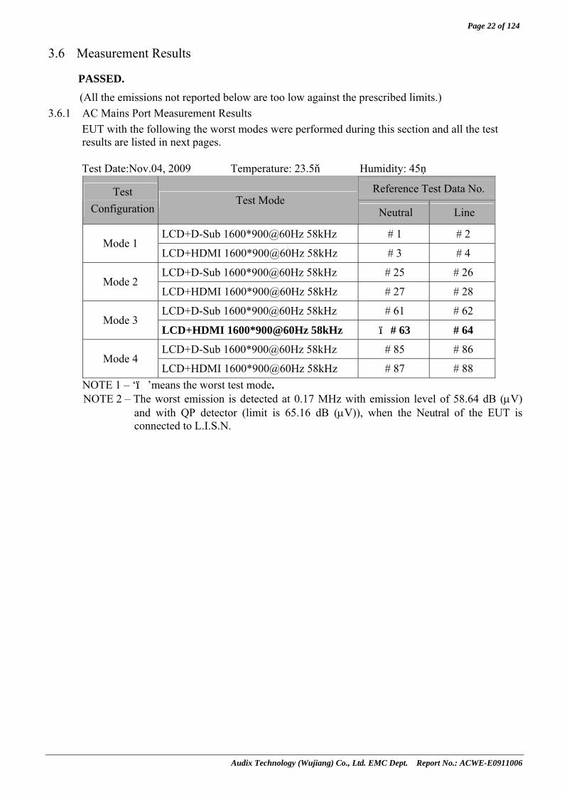
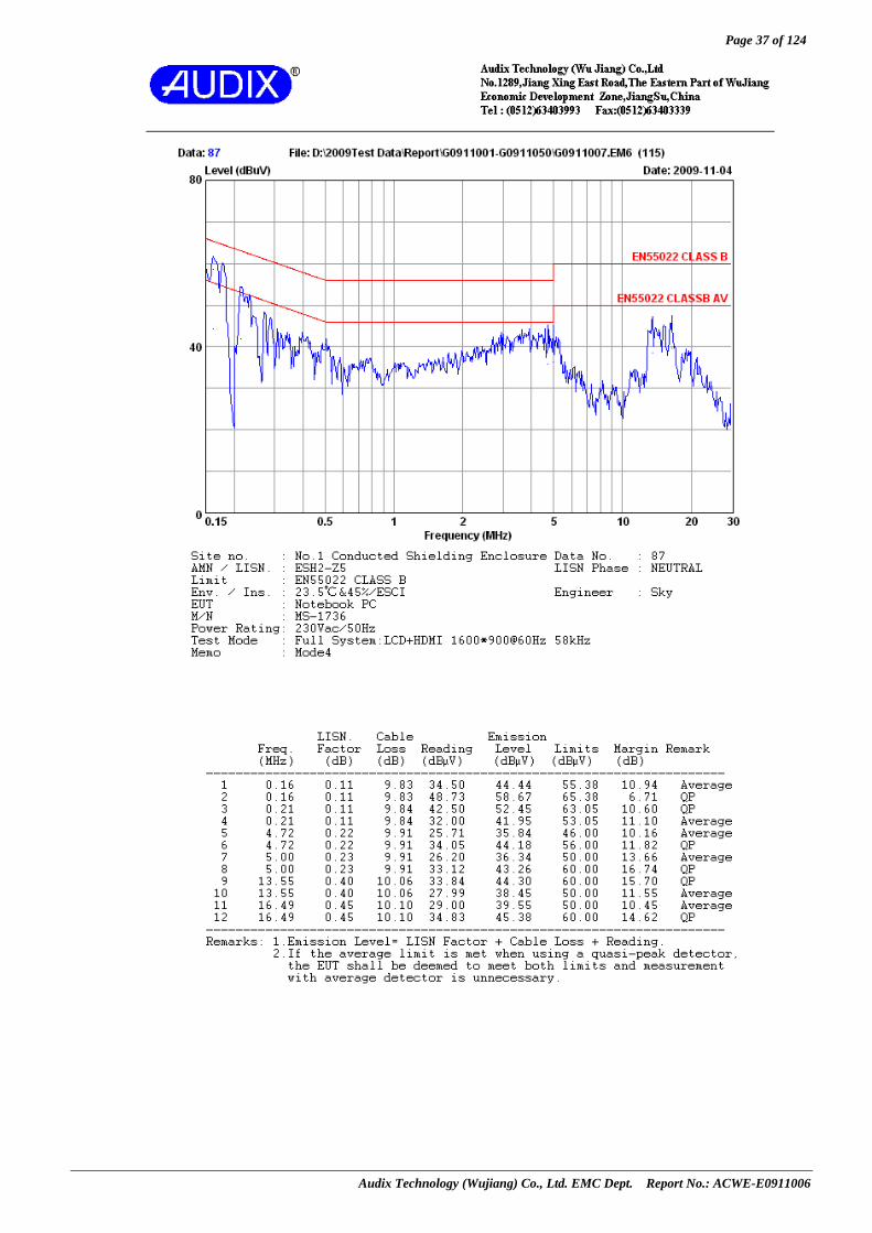
3.6 Measurement Results
PASSED. (All the emissions not reported below are too low against the prescribed limits.)
3.6.1 AC Mains Port Measurement Results EUT with the following the worst modes were performed during this section and all the test results are listed in next pages. Test Date:Nov.04, 2009 Temperature: 23.5 Humidity: 45%
Reference Test Data No. Test Configuration
Test Mode Neutral Line
LCD+D-Sub 1600*900@60Hz 58kHz # 1 # 2 Mode 1
LCD+HDMI 1600*900@60Hz 58kHz # 3 # 4
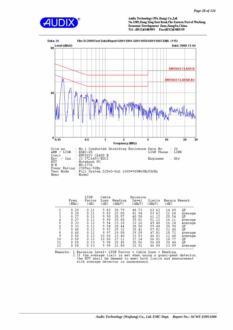
LCD+D-Sub 1600*900@60Hz 58kHz # 25 # 26 Mode 2
LCD+HDMI 1600*900@60Hz 58kHz # 27 # 28
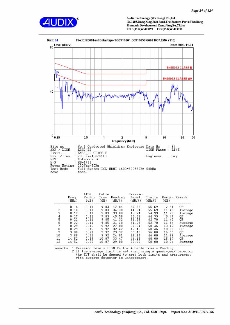
LCD+D-Sub 1600*900@60Hz 58kHz # 61 # 62 Mode 3
LCD+HDMI 1600*900@60Hz 58kHz # ※ 63 # 64
LCD+D-Sub 1600*900@60Hz 58kHz # 85 # 86 Mode 4
LCD+HDMI 1600*900@60Hz 58kHz # 87 # 88 NOTE 1 – ‘※’means the worst test mode. NOTE 2 – The worst emission is detected at 0.17 MHz with emission level of 58.64 dB (μV)
and with QP detector (limit is 65.16 dB (μV)), when the Neutral of the EUT is connected to L.I.S.N.

Page 23 of 124
Audix Technology (Wujiang) Co., Ltd. EMC Dept. Report No.: ACWE-E0911006

Page 24 of 124
Audix Technology (Wujiang) Co., Ltd. EMC Dept. Report No.: ACWE-E0911006

Page 25 of 124
Audix Technology (Wujiang) Co., Ltd. EMC Dept. Report No.: ACWE-E0911006

Page 26 of 124
Audix Technology (Wujiang) Co., Ltd. EMC Dept. Report No.: ACWE-E0911006

Page 27 of 124
Audix Technology (Wujiang) Co., Ltd. EMC Dept. Report No.: ACWE-E0911006
Page 28 of 124
Audix Technology (Wujiang) Co., Ltd. EMC Dept. Report No.: ACWE-E0911006

Page 29 of 124
Audix Technology (Wujiang) Co., Ltd. EMC Dept. Report No.: ACWE-E0911006

Page 30 of 124
Audix Technology (Wujiang) Co., Ltd. EMC Dept. Report No.: ACWE-E0911006

Page 31 of 124
Audix Technology (Wujiang) Co., Ltd. EMC Dept. Report No.: ACWE-E0911006

Page 32 of 124
Audix Technology (Wujiang) Co., Ltd. EMC Dept. Report No.: ACWE-E0911006

Page 33 of 124
Audix Technology (Wujiang) Co., Ltd. EMC Dept. Report No.: ACWE-E0911006
Page 34 of 124
Audix Technology (Wujiang) Co., Ltd. EMC Dept. Report No.: ACWE-E0911006

Page 35 of 124
Audix Technology (Wujiang) Co., Ltd. EMC Dept. Report No.: ACWE-E0911006

Page 36 of 124
Audix Technology (Wujiang) Co., Ltd. EMC Dept. Report No.: ACWE-E0911006
Page 37 of 124
Audix Technology (Wujiang) Co., Ltd. EMC Dept. Report No.: ACWE-E0911006

Page 38 of 124
Audix Technology (Wujiang) Co., Ltd. EMC Dept. Report No.: ACWE-E0911006

Page 39 of 124
Audix Technology (Wujiang) Co., Ltd. EMC Dept. Report No.: ACWE-E0911006
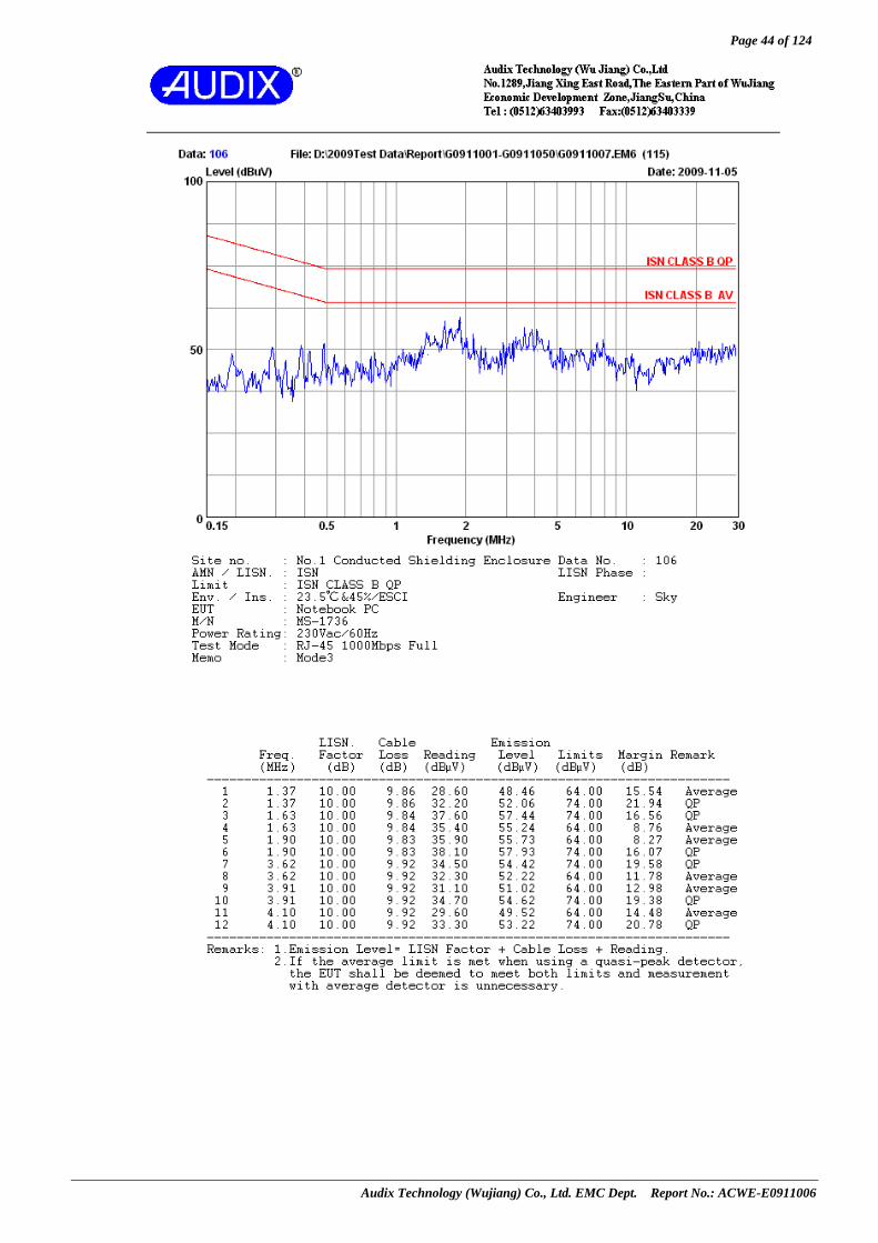
3.6.2 Telecommunication Ports Measurement Results The telecommunication ports contained RJ45 port; all the measurement results are listed in next pages. Test Date: Nov.05, 2009 Temperature: 23.5 Humidity: 45%
Test Configuration
Test Mode Reference Test Data No.
RJ45 10Mbps Full #102
RJ45 10Mbps Half #103
RJ45 100Mbps Full # 104
RJ45 100Mbps Half # 105
Mode 3
‘※RJ45 1000Mbps Full # 106
NOTE 1 – ‘※’means the worst test mode. NOTE 2 – The worst emission is detected at 1.9 MHz with emission level of 55.73 dB (μV) and
with Average detector (limit is 64 dB (μV)), when the RJ45 port of the EUT is connected to I.S.N.

Page 40 of 124
Audix Technology (Wujiang) Co., Ltd. EMC Dept. Report No.: ACWE-E0911006

Page 41 of 124
Audix Technology (Wujiang) Co., Ltd. EMC Dept. Report No.: ACWE-E0911006

Page 42 of 124
Audix Technology (Wujiang) Co., Ltd. EMC Dept. Report No.: ACWE-E0911006

Page 43 of 124
Audix Technology (Wujiang) Co., Ltd. EMC Dept. Report No.: ACWE-E0911006
Page 44 of 124
Audix Technology (Wujiang) Co., Ltd. EMC Dept. Report No.: ACWE-E0911006

Page 45 of 124
Audix Technology (Wujiang) Co., Ltd. EMC Dept. Report No.: ACWE-E0911006
4 RADIATED DISTURBANCE MEASUREMENT
4.1 Test Equipment The following test equipment was used during the radiated emission measurement:
(At 10m Semi-Anechoic Chamber) Item Type Manufacturer Model No. Serial No. Last Cal. Next Cal.
1. Spectrum Analyzer Agilent E7405A MY45107028 2009-03-25 2010-03-242. Spectrum Analyzer Agilent E7405A MY45107030 2009-03-25 2010-03-243. Pre-Amplifier Agilent 8447D 2944A10918 2009-08-11 2010-08-104. Pre-Amplifier Agilent 8447D 2944A10922 2009-08-11 2010-08-10
5. Bi-log Antenna
(Horizontal) Schaffner CBL6112D 22251 2009-05-05 2010-05-04
6. Bi-log Antenna
(Vertical) Schaffner CBL6112D 22253 2009-05-05 2010-05-04
7. Test Receiver R&S ESCI 100351 2009-01-07 2010-01-068. 50Ω Coaxial Switch # 1 ANRITSU MP59B 6200547935 2009-08-11 2010-08-109. 50Ω Coaxial Switch # 2 ANRITSU MP59B 6200547937 2009-08-11 2010-08-1010. 50Ω Coaxial Switch # 3 ANRITSU MP59B 6200547938 2009-08-11 2010-08-1011. Microwave amplifier Agilent 8449B 3008A02229 2009-03-25 2010-03-2412 RF Cable Yuhang CSYH 001 2009-08-14 2010-08-1313. RF Cable Yuhang CSYH 002 2009-08-14 2010-08-1314. RF Cable Yuhang CSYH 003 2009-08-14 2010-08-1315. RF Cable Yuhang CSYH 004 2009-08-14 2010-08-1316. RF Cable Yuhang CSYH 005 2009-08-14 2010-08-1317. RF Cable Yuhang CSYH 006 2009-08-14 2010-08-1318. RF Cable Yuhang CSYH 007 2009-08-14 2010-08-1319. RF Cable Yuhang CSYH 008 2009-08-14 2010-08-1320. RF Cable Yuhang CSYH 009 2009-08-14 2010-08-1321. RF Cable Yuhang CSYH 010 2009-08-14 2010-08-13
22. RF Cable Huber+Suhner SUCOFLEX 102 28571 2009-04-01 2010-03-31
23. RF Cable Huber+Suhner SUCOFLEX 102 28579 2009-04-01 2010-03-31
Page 46 of 124
Audix Technology (Wujiang) Co., Ltd. EMC Dept. Report No.: ACWE-E0911006
(No. 1 3m Semi-Anechoic Chamber)
Item Type Manufacturer Model No. Serial No. Last Cal. Next Cal. 1 Preamplifier Agilent 8447D 2944A10921 2009-03-25 2010-03-24
2 Spectrum Analyzer Agilent E7405A MY45107604 2009-03-25 2010-03-24
3 Bi-log Antenna (30MHz~1GHz) Schaffner CBL6112D 22250 2009-05-05 2010-05-04
4. Horn Antenna (1GHz~6GHz)
ESCO 3115 00062593 2009-05-05 2010-05-04
5. Test Receiver R&S ESCI 100361 2009-03-25 2010-03-24
6. 50Ω Coaxial Switch Anritsu MP59B 6200547935 2009-08-11 2010-08-10
7. RF Cable Yuhang CSYH 001 2009-08-14 2010-08-138. RF Cable Yuhang CSYH 002 2009-08-14 2010-08-139. RF Cable Yuhang CSYH 003 2009-08-14 2010-08-13
10. RF Cable Yuhang CSYH 004 2009-08-14 2010-08-13
11. RF Cable Huber+Suhner SUCOFLEX 102 28575 2009-04-01 2010-03-31
12. RF Cable Huber+Suhner SUCOFLEX 102 28570 2009-04-01 2010-03-31
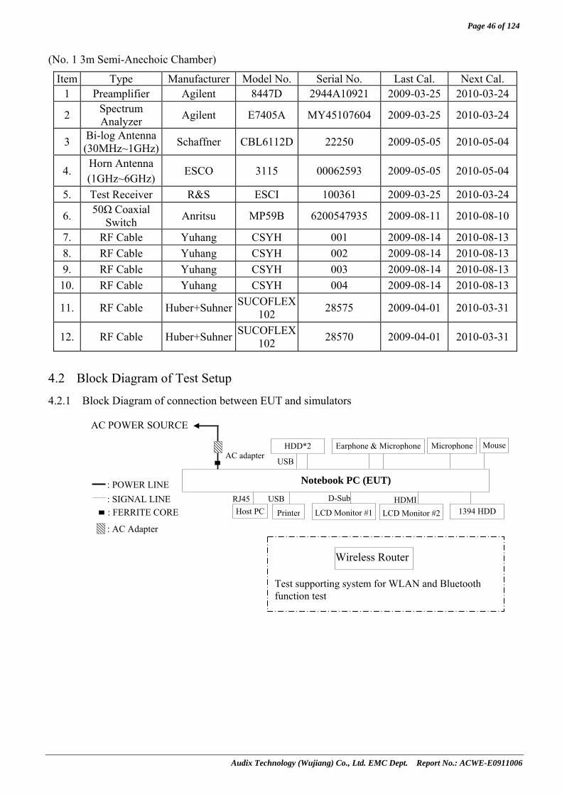
4.2 Block Diagram of Test Setup
4.2.1 Block Diagram of connection between EUT and simulators
AC POWER SOURCE
: POWER LINE: SIGNAL LINE
Notebook PC (EUT)
LCD Monitor #1
Earphone & Microphone
Host PC Printer
AC adapter
: FERRITE CORE
HDD*2
LCD Monitor #2 HDMI D-Sub USB RJ45
USB
: AC Adapter
Microphone
1394 HDD
Wireless Router
Test supporting system for WLAN and Bluetooth function test
Mouse

Page 47 of 124
Audix Technology (Wujiang) Co., Ltd. EMC Dept. Report No.: ACWE-E0911006
4.2.2 No. 1 10m Semi-Anechoic Chamber Setup Diagram (Test distance: 10m)
4.2.3 3m Semi-Anechoic Chamber Setup Diagram (Test distance: 3m)
4.3 Limits for Radiated Disturbance (30MHz~1000MHz) (EN 55022, Class B) FREQUENCY DISTANCE FIELD STRENGTHS LIMITS
(MHz) (Meters) (dBμV/m) 30 ~ 230 10 30
230 ~ 1000 10 37 Note: (1) The tighter limit shall apply at the edge between two frequency bands.
(2) Distance refers to the distance in meters between the measuring instrument antenna and the closed point of any part of the E.U.T.
0.8m
10 METERS
ANTENNA ELEVATION VARIES FROM 1 TO 4 METERS
ANTENNA TOWER
GROUND PLANE
TURN TABLE
EUT
0.8m
3 METERS
ANTENNA ELEVATION VARIES FROM 1 TO 4 METERS
ANTENNA TOWER
GROUND PLANE
TURN TABLE
EUT
ABSORBER

Page 48 of 124
Audix Technology (Wujiang) Co., Ltd. EMC Dept. Report No.: ACWE-E0911006
4.4 Limits for Radiated Disturbance (1GHz~6GHz) (EN55022, Class B) FREQUENCY DISTANCE AVERAGE LIMITE PEAK LIMITE
(GHz) (Meters) (dBμV/m) (dBμV/m) 1~ 3 3 50 70 3~ 6 3 54 74
Note: (1) The lower limit applies at the transition frequency.
4.5 Test Procedure The measuring process is according to EN 55022(CISPR Pub. 22) and laboratory internal procedure TKC-301-024. In the radiated disturbance measurement, the EUT and all simulators were set up on a non-metallic turn table which was 0.8 meters above the ground plane. Measurement distance between EUT and receiving antennas was set at 10 meters at 30MHz~1000MHz and 3 meters at 1000MHz~6000MHz. The specified distance is the distance between the antennas and the closest periphery of EUT. During the radiated measurement, the EUT was rotated 360° and receiving antennas were moved from 1 ~ 4 meters for finding maximum emission. Two receiving antennas were used for both horizontal and vertical polarization detection for 30MHz~1GHz, One receiving antennas was used for both horizontal and vertical polarization detection for 1GHz~6GHz (the absorbing material was added when testing of 1GHz~6GHz was done). All cables or wires placement were verified to find out the maximum emission. The bandwidth of measuring receiver (or spectrum analyzer) was set to:
RBW (120 kHz), VBW (1MHz) for QP detector below 1GHz RBW (1 MHz), VBW (1MHz) for Peak detector above 1GHz RBW (1 MHz), VBW (10 Hz) for Average detector above 1GHz
which is defined against CISPR16-1-1 6.4.3 section.
The required frequency band (30 MHz ~ 6000 MHz) was pre-scanned with peak detector; all final measurements were measured with quasi-peak detector below 1GHz, measured with average detector and peak detector above 1GHz. The emission level is calculated automatically by the test system which uses the following equation: 1. For 30-1000MHz measurement:
Emission Level (dBμV/m) = Meter-Reading (dBμV)+Antenna Factor (dB/m)+Cable Loss (dB) 2. For 1000-6000MHz measurement:
Emission Level (dBμV/m) = Meter-Reading (dBμV)+Antenna Factor (dB/m)+Cable Loss(dB) -Pre-amplifier factor (dBμV)

Page 49 of 124
Audix Technology (Wujiang) Co., Ltd. EMC Dept. Report No.: ACWE-E0911006
4.6 Measurement Results PASSED. (All the emissions not reported below are too low against the prescribed limits.)
EUT with four configurations (Mode 1 ~ Mode 4) was pre-measured and the pre-scanned data was attached in appendix I, Therein, the worst case Mode 1 was re-measured. All the measurement results are listed in next pages.
4.6.1 For 30MHz~1GHz Test Date: Nov.06, 2009 Temperature: 24.9 Humidity: 43%
Reference Test Data No. Test Configuration
Test Mode Neutral Line
LCD+D-Sub 1600*900@60Hz 58kHz # 1 # 2 Mode 1
※LCD+HDMI 1600*900@60Hz 58kHz # 3 # 4
NOTE 1 - ‘※’ means the worst test mode. NOTE 2 - 0° was the table front facing the antenna. Degree is calculated from 0° clockwise
facing the antenna. NOTE 3 - The worst emission at horizontal polarization was detected at 959.26MHz with
emission level of 31.57 dBμV/m (limit is 37.00dBμV/m), when the antenna was 1.8m height and the turntable was at 260°. The worst emission at vertical polarization was detected at 963.14 MHz with emission level of 32.04 dBμV/m (limit is 37.00 dBμV/m), when the antenna was 1.4m height and the turntable was at 120°.

Page 50 of 124
Audix Technology (Wujiang) Co., Ltd. EMC Dept. Report No.: ACWE-E0911006

Page 51 of 124
Audix Technology (Wujiang) Co., Ltd. EMC Dept. Report No.: ACWE-E0911006

Page 52 of 124
Audix Technology (Wujiang) Co., Ltd. EMC Dept. Report No.: ACWE-E0911006

Page 53 of 124
Audix Technology (Wujiang) Co., Ltd. EMC Dept. Report No.: ACWE-E0911006
Page 54 of 124
Audix Technology (Wujiang) Co., Ltd. EMC Dept. Report No.: ACWE-E0911006
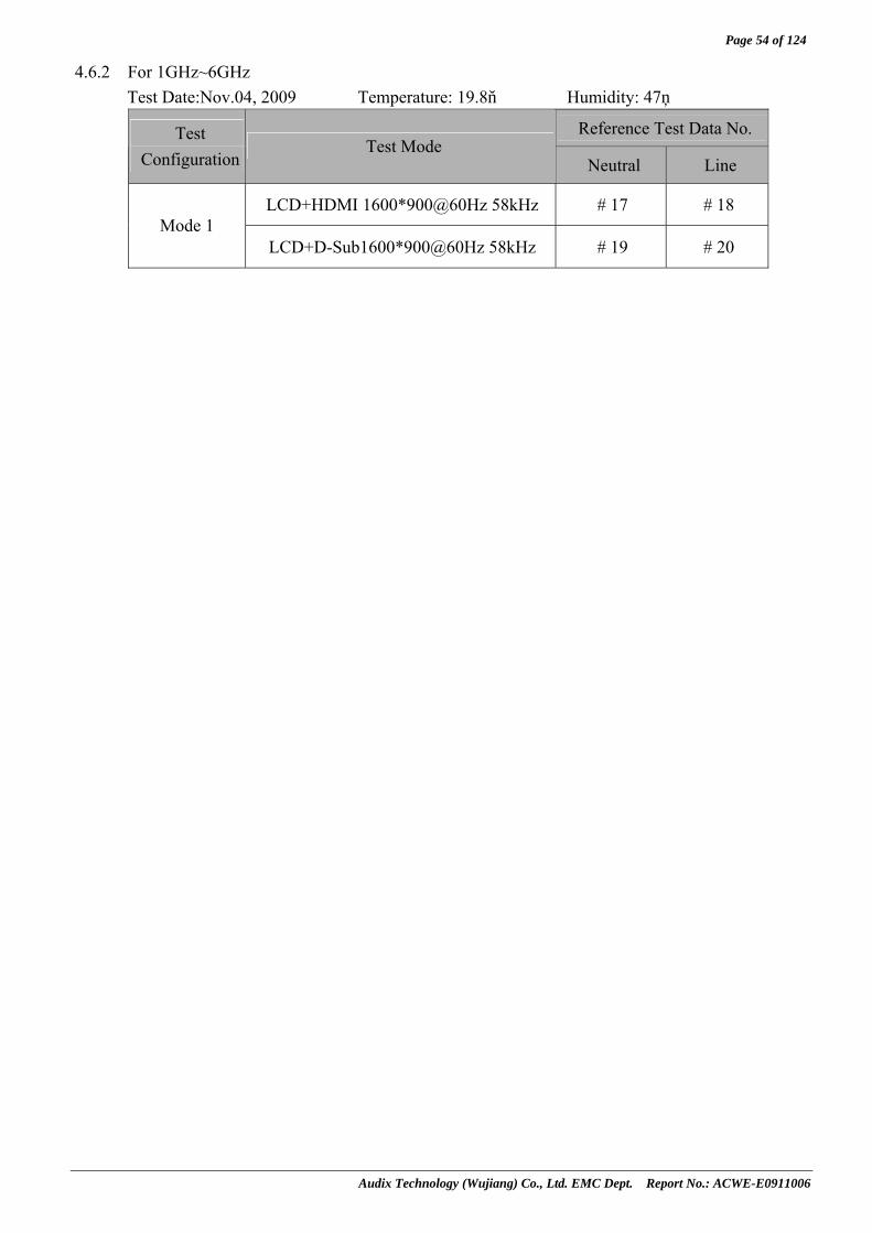
4.6.2 For 1GHz~6GHz Test Date:Nov.04, 2009 Temperature: 19.8 Humidity: 47%
Reference Test Data No. Test Configuration
Test Mode Neutral Line
LCD+HDMI 1600*900@60Hz 58kHz # 17 # 18 Mode 1
LCD+D-Sub1600*900@60Hz 58kHz # 19 # 20

Page 55 of 124
Audix Technology (Wujiang) Co., Ltd. EMC Dept. Report No.: ACWE-E0911006

Page 56 of 124
Audix Technology (Wujiang) Co., Ltd. EMC Dept. Report No.: ACWE-E0911006

Page 57 of 124
Audix Technology (Wujiang) Co., Ltd. EMC Dept. Report No.: ACWE-E0911006

Page 58 of 124
Audix Technology (Wujiang) Co., Ltd. EMC Dept. Report No.: ACWE-E0911006

Page 59 of 124
Audix Technology (Wujiang) Co., Ltd. EMC Dept. Report No.: ACWE-E0911006
5 POWER HARMONICS AND FLICKER MEASUREMENT
5.1 Test Equipment Item Type Manufacturer Model No. Serial No. Last Cal. Next Cal.
1. Compliance Test System #1
California Instrument 5001iX 57305 2009-08-11 2010-08-10
2. Compliance Test System #2
California Instrument PASC-1 72485 2009-08-11 2010-08-10
5.2 Block Diagram of Test Setup
5.3 Test Standard EN 61000-3-2/2006 and EN 61000-3-3/1995 +A1/2001+A2/2005
5.4 Test Procedure The measuring process is according to EN 61000-3-2/2006 and EN 61000-3-3/1995 +A1/2001+A2/2005 and laboratory internal procedure TKC-301-026.
Compliance Test System #2
Compliance Test System #1
: POWER LINE : SIGNAL LINE
: FERRITE CORE
Notebook PC (EUT)
LCD Monitor #1
Earphone & Microphone
Host PC Printer
HDD*2
LCD Monitor #2
USB
USB RJ45 D-Sub HDMI
: AC Adapter
Microphone
1394 HDD
Wireless Router
Test supporting system for WLAN and Bluetooth function test
Page 60 of 124
Audix Technology (Wujiang) Co., Ltd. EMC Dept. Report No.: ACWE-E0911006
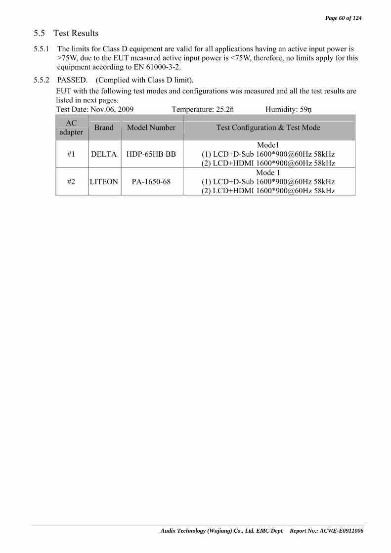
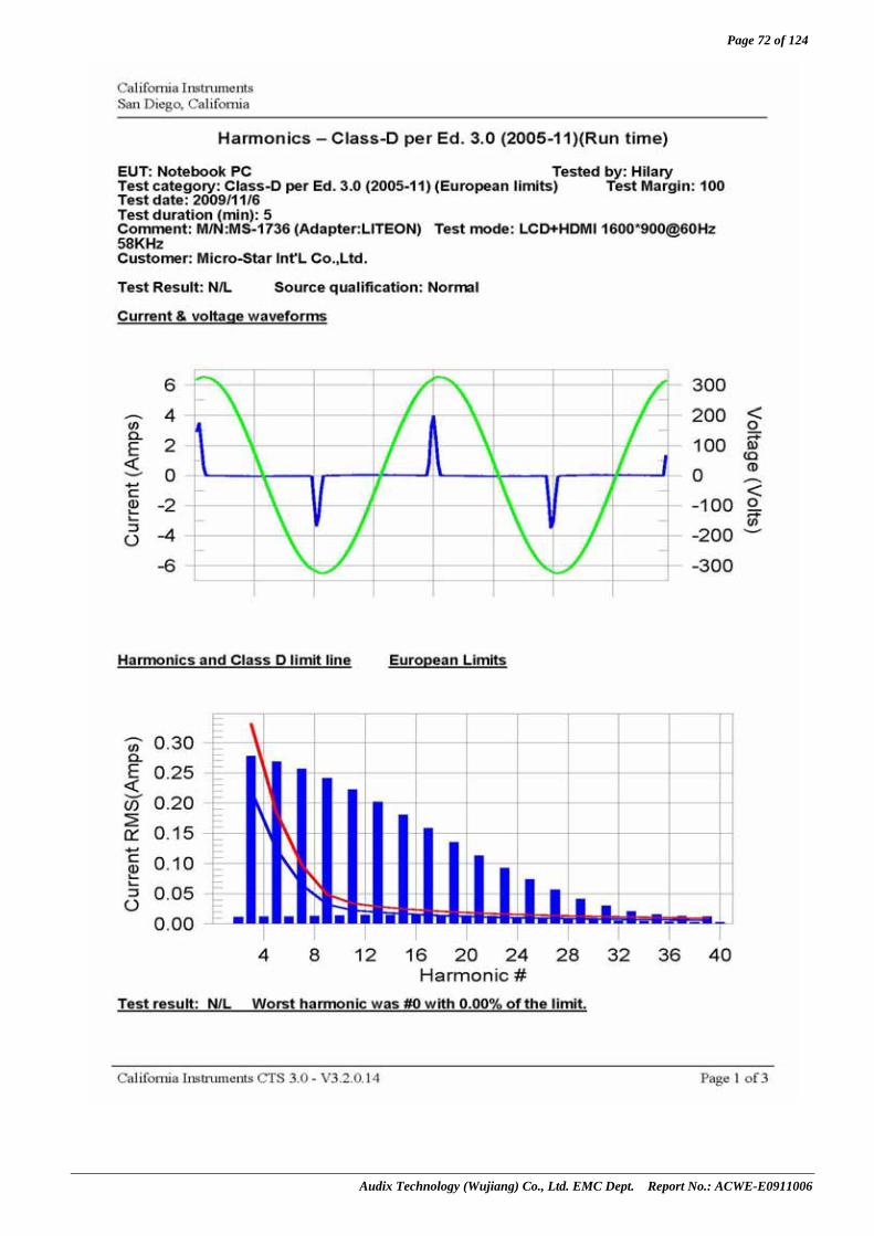
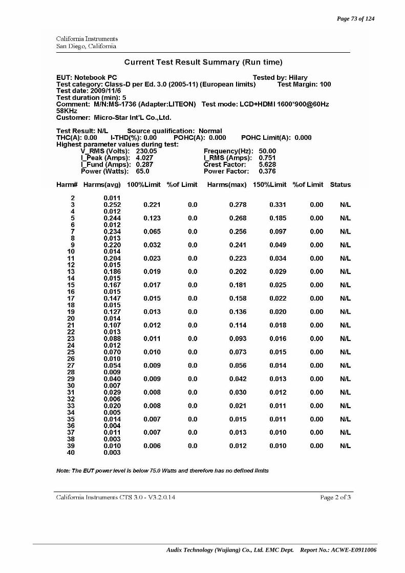
5.5 Test Results
5.5.1 The limits for Class D equipment are valid for all applications having an active input power is >75W, due to the EUT measured active input power is <75W, therefore, no limits apply for this equipment according to EN 61000-3-2.
5.5.2 PASSED. (Complied with Class D limit). EUT with the following test modes and configurations was measured and all the test results are listed in next pages. Test Date: Nov.06, 2009 Temperature: 25.2 Humidity: 59%
AC adapter Brand Model Number Test Configuration & Test Mode
#1 DELTA HDP-65HB BB Mode1
(1) LCD+D-Sub 1600*900@60Hz 58kHz (2) LCD+HDMI 1600*900@60Hz 58kHz
#2 LITEON PA-1650-68 Mode 1
(1) LCD+D-Sub 1600*900@60Hz 58kHz (2) LCD+HDMI 1600*900@60Hz 58kHz

Page 61 of 124
Audix Technology (Wujiang) Co., Ltd. EMC Dept. Report No.: ACWE-E0911006
5.5.3 Mode1 & Adapter #1

Page 62 of 124
Audix Technology (Wujiang) Co., Ltd. EMC Dept. Report No.: ACWE-E0911006

Page 63 of 124
Audix Technology (Wujiang) Co., Ltd. EMC Dept. Report No.: ACWE-E0911006

Page 64 of 124
Audix Technology (Wujiang) Co., Ltd. EMC Dept. Report No.: ACWE-E0911006

Page 65 of 124
Audix Technology (Wujiang) Co., Ltd. EMC Dept. Report No.: ACWE-E0911006

Page 66 of 124
Audix Technology (Wujiang) Co., Ltd. EMC Dept. Report No.: ACWE-E0911006

Page 67 of 124
Audix Technology (Wujiang) Co., Ltd. EMC Dept. Report No.: ACWE-E0911006

Page 68 of 124
Audix Technology (Wujiang) Co., Ltd. EMC Dept. Report No.: ACWE-E0911006

Page 69 of 124
Audix Technology (Wujiang) Co., Ltd. EMC Dept. Report No.: ACWE-E0911006
5.5.4 Mode1 & Adapter #2

Page 70 of 124
Audix Technology (Wujiang) Co., Ltd. EMC Dept. Report No.: ACWE-E0911006

Page 71 of 124
Audix Technology (Wujiang) Co., Ltd. EMC Dept. Report No.: ACWE-E0911006
Page 72 of 124
Audix Technology (Wujiang) Co., Ltd. EMC Dept. Report No.: ACWE-E0911006
Page 73 of 124
Audix Technology (Wujiang) Co., Ltd. EMC Dept. Report No.: ACWE-E0911006

Page 74 of 124
Audix Technology (Wujiang) Co., Ltd. EMC Dept. Report No.: ACWE-E0911006

Page 75 of 124
Audix Technology (Wujiang) Co., Ltd. EMC Dept. Report No.: ACWE-E0911006

Page 76 of 124
Audix Technology (Wujiang) Co., Ltd. EMC Dept. Report No.: ACWE-E0911006

Page 77 of 124
Audix Technology (Wujiang) Co., Ltd. EMC Dept. Report No.: ACWE-E0911006
6 ELECTROSTATIC DISCHARGE IMMUNITY TEST
6.1 Test Equipment Item Type Manufacturer Model No. Serial No. Last Cal. Next Cal.
1. ESD Simulator NoiseKen ESS-2000 ESS07X7519 2008-12-23 2009-12-22
6.2 Block Diagram of Test Setup
6.3 Test Standard EN 55024/1998+A1/2001+A2/2003 【IEC 61000-4-2/2008, Test Level : Contact Discharge: ±4kV, Air Discharge: ±8kV】
6.4 Severity Levels and Performance Criterion
6.4.1 Severity level
Level Test Voltage Contact Discharge (kV)
Test Voltage Air Discharge (kV)
1. 2 2 2. 4 4 3. 6 8 4. 8 15 X Special Special
6.4.2 Performance criterion:B
: AIR /CONTACT DISCHARGE
ESD Simulator
AC SOURCE
: POWER LINE : SIGNAL LINE : FERRITE CORE
Notebook PC (EUT)
LCD Monitor #1
Earphone & Microphone
Host PC Printer
HDD*2
LCD Monitor #2
USB
USB RJ45 D-Sub HDMI
: AC Adapter
Microphone
1394 HDD
Wireless Router
Test supporting system for WLAN and Bluetooth function test
Mouse

Page 78 of 124
Audix Technology (Wujiang) Co., Ltd. EMC Dept. Report No.: ACWE-E0911006
6.5 Test Procedure The measuring process is according to EN 55024/1998+A1/2001+A2/2003(IEC 61000-4-2/2008) and laboratory internal procedure TKC-301-020.
6.5.1 Air Discharge: This test is done on a non-conductive surface. The round discharge tip of the discharge electrode shall be approached as fast as possible to touch the EUT. After each discharge, the ESD generator discharge electrode shall be removed from the EUT. The generator is then ret rigged for a new single discharge and repeated 10 discharges each at positive and negative polarity for each reselected test point. This procedure shall be repeated until all the air discharge completed.
6.5.2 Contact Discharge: All the procedure shall be same as 6.5.1. Except that the tip of the discharge electrode shall touch the EUT conductive surfaces & repeated 25 discharges each at positive and negative polarity for each test point before the discharge switch is operated.
6.5.3 Indirect discharge for horizontal coupling plane: At least 25 discharges each at positive and negative polarity shall be applied to the horizontal coupling plane, at points on each side of the EUT. The ESD generator positions vertically at a distance of 0.1m from the EUT and with the discharge electrode touching the coupling plane.
6.5.4 Indirect discharge for vertical coupling plane: At least 25 discharges each at positive and negative polarity shall be applied to the center of one vertical edge of the coupling plane. The coupling plane, of dimensions 0.5m X 0.5m, is placed parallel to, and positioned at a distance of 0.1m from the EUT. Discharges shall be applied to the coupling plane, with this plane in sufficient different positions that the four faces of the EUT are completely illuminated.
6.5.5 For above tests, the voltage was increased from the minimum to the selected test level.
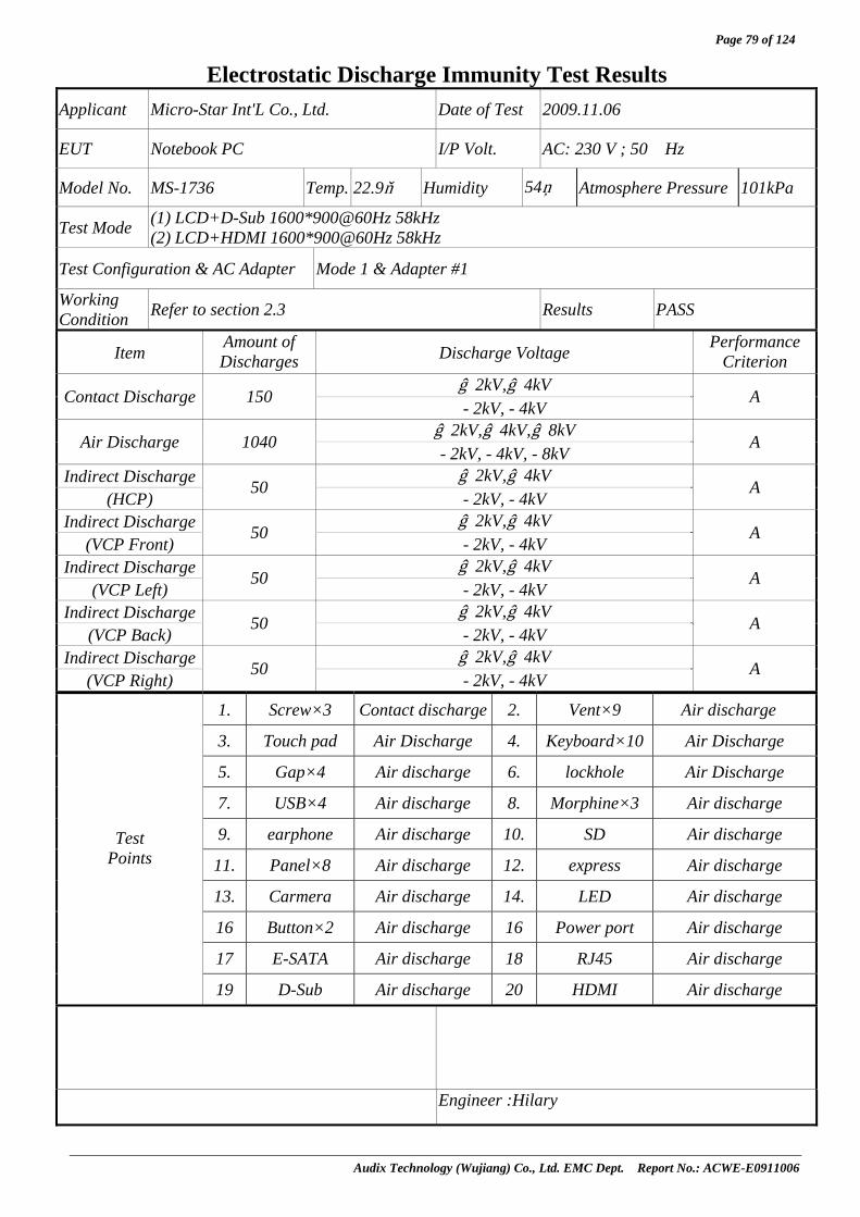
6.6 Test Results PASSED. (Complied with Criterion A) EUT with the following test modes and configurations was tested and all the test results are listed in next pages.
AC adapter Brand Model Number Test Configuration & Test Mode
#1 DELTA HDP-65HB BB Mode 1
(1) LCD+D-Sub 1600*900@60Hz 58kHz (2) LCD+HDMI 1600*900@60Hz 58kHz
#2 LITEON PA-1650-68 Mode 1
(1) LCD+D-Sub 1600*900@60Hz 58kHz (2) LCD+HDMI 1600*900@60Hz 58kHz
Page 79 of 124
Audix Technology (Wujiang) Co., Ltd. EMC Dept. Report No.: ACWE-E0911006
Electrostatic Discharge Immunity Test Results Applicant Micro-Star Int'L Co., Ltd. Date of Test 2009.11.06
EUT Notebook PC I/P Volt. AC: 230 V ; 50 Hz
Model No. MS-1736 Temp. 22.9 Humidity 54% Atmosphere Pressure 101kPa
Test Mode (1) LCD+D-Sub 1600*900@60Hz 58kHz (2) LCD+HDMI 1600*900@60Hz 58kHz
Test Configuration & AC Adapter Mode 1 & Adapter #1
Working Condition Refer to section 2.3 Results PASS
Item Amount of Discharges Discharge Voltage Performance
Criterion ﹢2kV,﹢4kV
Contact Discharge 150 - 2kV, - 4kV
A
﹢2kV,﹢4kV,﹢8kV Air Discharge 1040
- 2kV, - 4kV, - 8kV A
Indirect Discharge ﹢2kV,﹢4kV (HCP)
50 - 2kV, - 4kV
A
Indirect Discharge ﹢2kV,﹢4kV (VCP Front)
50 - 2kV, - 4kV
A
Indirect Discharge ﹢2kV,﹢4kV (VCP Left)
50 - 2kV, - 4kV
A
Indirect Discharge ﹢2kV,﹢4kV (VCP Back)
50 - 2kV, - 4kV
A
Indirect Discharge ﹢2kV,﹢4kV (VCP Right)
50 - 2kV, - 4kV
A
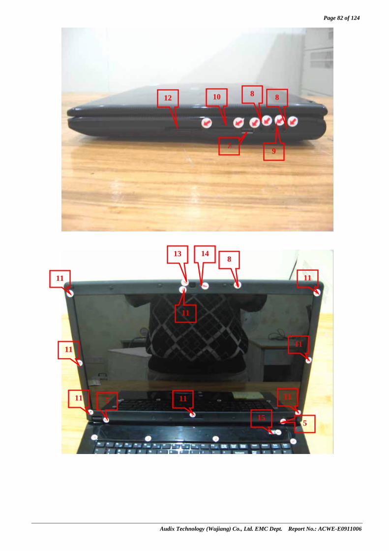
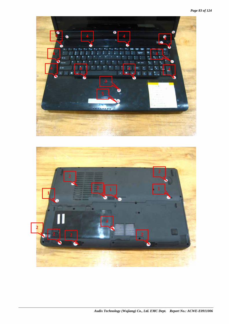
1. Screw×3 Contact discharge 2. Vent×9 Air discharge
3. Touch pad Air Discharge 4. Keyboard×10 Air Discharge
5. Gap×4 Air discharge 6. lockhole Air Discharge
7. USB×4 Air discharge 8. Morphine×3 Air discharge
9. earphone Air discharge 10. SD Air discharge
11. Panel×8 Air discharge 12. express Air discharge
13. Carmera Air discharge 14. LED Air discharge
16 Button×2 Air discharge 16 Power port Air discharge
17 E-SATA Air discharge 18 RJ45 Air discharge
Test Points
19 D-Sub Air discharge 20 HDMI Air discharge
Engineer :Hilary

Page 80 of 124
Audix Technology (Wujiang) Co., Ltd. EMC Dept. Report No.: ACWE-E0911006
Electrostatic Discharge Immunity Test Results Applicant Micro-Star Int'L Co., Ltd. Date of Test 2009.11.06
EUT Notebook PC I/P Volt. AC: 230 V ; 50 Hz
Model No. MS-1736 Temp. 22.9 Humidity 54% Atmosphere Pressure 101kPa
Test Mode (1) LCD+D-Sub 1600*900@60Hz 58kHz (2) LCD+HDMI 1600*900@60Hz 58kHz
Test Configuration & AC Adapter Mode 1 & Adapter #2
Working Condition Refer to section 2.3 Results PASS
Item Amount of Discharges Discharge Voltage Performance
Criterion ﹢2kV,﹢4kV
Contact Discharge 150 - 2kV, - 4kV
A
﹢2kV,﹢4kV,﹢8kV Air Discharge 1040
- 2kV, - 4kV, - 8kV A
Indirect Discharge ﹢2kV,﹢4kV (HCP)
50 - 2kV, - 4kV
A
Indirect Discharge ﹢2kV,﹢4kV (VCP Front)
50 - 2kV, - 4kV
A
Indirect Discharge ﹢2kV,﹢4kV (VCP Left)
50 - 2kV, - 4kV
A
Indirect Discharge ﹢2kV,﹢4kV (VCP Back)
50 - 2kV, - 4kV
A
Indirect Discharge ﹢2kV,﹢4kV (VCP Right)
50 - 2kV, - 4kV
A
1. Screw×3 Contact discharge 2. Vent×9 Air discharge
3. Touch pad Air Discharge 4. Keyboard×10 Air Discharge
5. Gap×4 Air discharge 6. lockhole Air Discharge
7. USB×4 Air discharge 8. Morphine×3 Air discharge
9. earphone Air discharge 10. SD Air discharge
11. Panel×8 Air discharge 12. express Air discharge
13. Carmera Air discharge 14. LED Air discharge
16 Button×2 Air discharge 16 Power port Air discharge
17 E-SATA Air discharge 18 RJ45 Air discharge
Test Points
19 D-Sub Air discharge 20 HDMI Air discharge
Engineer :Hilary

Page 81 of 124
Audix Technology (Wujiang) Co., Ltd. EMC Dept. Report No.: ACWE-E0911006
Photos of Discharge Points:
19 20 18 17 16
7 7
7
2
6 15 5
Page 82 of 124
Audix Technology (Wujiang) Co., Ltd. EMC Dept. Report No.: ACWE-E0911006
7
8 8
8
9
13
11
11
11 11 11
11
11
11
12 10
14
15
5
5
Page 83 of 124
Audix Technology (Wujiang) Co., Ltd. EMC Dept. Report No.: ACWE-E0911006
4
4
4 4 4 4
4
4 4 4
1 1 1
2 2 2
2
2
2
2
2
3
5
Page 84 of 124
Audix Technology (Wujiang) Co., Ltd. EMC Dept. Report No.: ACWE-E0911006
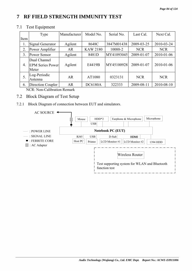
7 RF FIELD STRENGTH IMMUNITY TEST
7.1 Test Equipment
Item Type Manufacturer Model No. Serial No. Last Cal. Next Cal.
1. Signal Generator Agilent 8648C 3847M01438 2009-03-25 2010-03-242. Power Amplifier AR KAW 2180 10088-2 NCR NCR 3. Power Sensor Agilent 8481D MY41093045 2009-01-07 2010-01-06
4. Dual Channel EPM Series Power Meter
Agilent E4419B MY45100928 2009-01-07 2010-01-06
5. Log-Periodic Antenna AR AT1080 0323131 NCR NCR
6. Direction Coupler AR DC6180A 322333 2009-08-11 2010-08-10NCR: Non-Calibration Remark
7.2 Block Diagram of Test Setup
7.2.1 Block Diagram of connection between EUT and simulators.
AC SOURCE
: POWER LINE : SIGNAL LINE : FERRITE CORE
Notebook PC (EUT)
LCD Monitor #1
Earphone & Microphone
Host PC Printer
HDD*2
LCD Monitor #2
USB
USB RJ45 D-Sub HDMI
: AC Adapter
Microphone
HDMI
1394 HDD
Wireless Router
Test supporting system for WLAN and Bluetooth function test
Mouse

Page 85 of 124
Audix Technology (Wujiang) Co., Ltd. EMC Dept. Report No.: ACWE-E0911006
7.2.2 R/S Test Setup
7.3 Test Standard EN 55024/1998+A1/2001+A2/2003 【IEC 61000-4-3/2008, Test Level:2; Field strength: 3V/m】
7.4 Severity Levels and Performance Criterion
7.4.1 Severity level
Level Field Strength V/m
1. 1
2. 3
3. 10
X Special
7.4.2 Performance criterion:A
7.5 Test Procedure The measuring process is according to EN 55024/1998+A1/2001+A2/2003(IEC 61000-4-3/2008) and laboratory internal procedure TKC-301-021. The field sensor is placed on the EUT table (0.8 meter above the ground) which is 3 meters away from the transmitting antenna. Through the signal generator, power amplifier and transmitting antenna to produce a uniformity field strength (3V/m measured by field sensor) around the EUT table from frequency range 80MHz to 1GHzand records the signal generator‘s output level at the same time for whole measured frequency range. Then, put EUT and its simulators on the EUT turn table and keep them 3 meter away from the transmitting antenna which is mounted on an antenna tower and fixes at 1 meter height above the ground. Using the recorded signal generator’s output level to measure the EUT from frequency range 80MHz to 1GHz and both horizontal & vertical polarization of antenna must be set and measured. Each of the four sides of EUT must be faced this transmitting antenna and measures individually.
A CCD camera was put inside the chamber and through its display to monitor the EUT operational situation to judge the EUT performance criterion during measurement.
EUT
0.8 Meter
1 Meter
Anechoic Chamber
Control Room Direction Coupler
Signal Generator Personal Computer
3 Meters
Power Amp.
Power Sensor Power Monitor
Page 86 of 124
Audix Technology (Wujiang) Co., Ltd. EMC Dept. Report No.: ACWE-E0911006
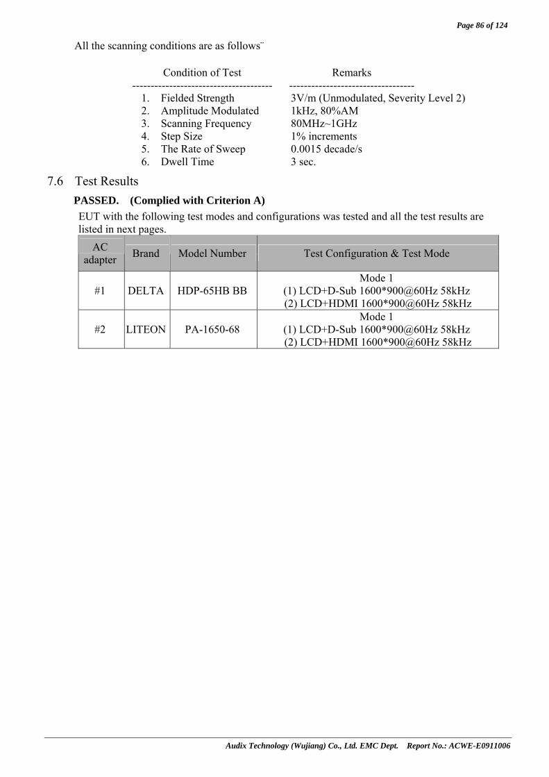
All the scanning conditions are as follows: Condition of Test Remarks -------------------------------------- ----------------------------------
1. Fielded Strength 3V/m (Unmodulated, Severity Level 2) 2. Amplitude Modulated 1kHz, 80%AM 3. Scanning Frequency 80MHz~1GHz 4. Step Size 1% increments 5. The Rate of Sweep 0.0015 decade/s 6. Dwell Time 3 sec.
7.6 Test Results PASSED. (Complied with Criterion A) EUT with the following test modes and configurations was tested and all the test results are listed in next pages.
AC adapter Brand Model Number Test Configuration & Test Mode
#1 DELTA HDP-65HB BB Mode 1
(1) LCD+D-Sub 1600*900@60Hz 58kHz (2) LCD+HDMI 1600*900@60Hz 58kHz
#2 LITEON PA-1650-68 Mode 1
(1) LCD+D-Sub 1600*900@60Hz 58kHz (2) LCD+HDMI 1600*900@60Hz 58kHz

Page 87 of 124
Audix Technology (Wujiang) Co., Ltd. EMC Dept. Report No.: ACWE-E0911006
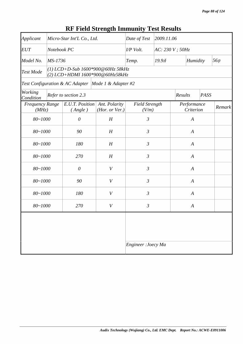
RF Field Strength Immunity Test Results
Applicant Micro-Star Int'L Co., Ltd. Date of Test 2009.11.06
EUT Notebook PC I/P Volt. AC: 230 V ; 50Hz
Model No. MS-1736 Temp. 19.9 Humidity 56%
Test Mode (1) LCD+D-Sub 1600*900@60Hz 58kHz (2) LCD+HDMI 1600*900@60Hz58kHz
Test Configuration & AC Adapter Mode 1 & Adapter #1
Working Condition Refer to section 2.3 Results PASS
Frequency Range (MHz)
E.U.T. Position ( Angle )
Ant. Polarity(Hor. or Ver.)
Field Strength (V/m)
Performance Criterion Remark
80~1000 0 H 3 A
80~1000 90 H 3 A
80~1000 180 H 3 A
80~1000 270 H 3 A
80~1000 0 V 3 A
80~1000 90 V 3 A
80~1000 180 V 3 A
80~1000 270 V 3 A
Engineer :Joecy Ma
Page 88 of 124
Audix Technology (Wujiang) Co., Ltd. EMC Dept. Report No.: ACWE-E0911006
RF Field Strength Immunity Test Results
Applicant Micro-Star Int'L Co., Ltd. Date of Test 2009.11.06
EUT Notebook PC I/P Volt. AC: 230 V ; 50Hz
Model No. MS-1736 Temp. 19.9 Humidity 56%
Test Mode (1) LCD+D-Sub 1600*900@60Hz 58kHz (2) LCD+HDMI 1600*900@60Hz58kHz
Test Configuration & AC Adapter Mode 1 & Adapter #2
Working Condition Refer to section 2.3 Results PASS
Frequency Range (MHz)
E.U.T. Position ( Angle )
Ant. Polarity(Hor. or Ver.)
Field Strength (V/m)
Performance Criterion Remark
80~1000 0 H 3 A
80~1000 90 H 3 A
80~1000 180 H 3 A
80~1000 270 H 3 A
80~1000 0 V 3 A
80~1000 90 V 3 A
80~1000 180 V 3 A
80~1000 270 V 3 A
Engineer :Joecy Ma
Page 89 of 124
Audix Technology (Wujiang) Co., Ltd. EMC Dept. Report No.: ACWE-E0911006
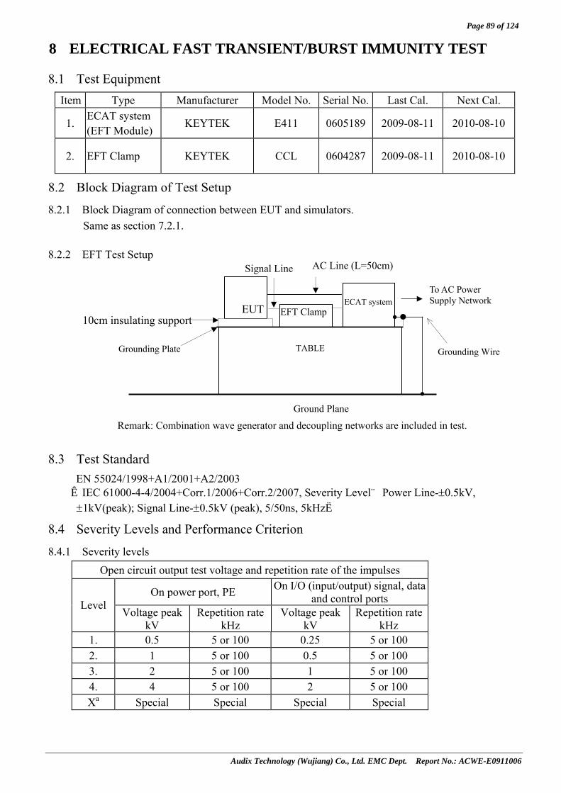
8 ELECTRICAL FAST TRANSIENT/BURST IMMUNITY TEST
8.1 Test Equipment Item Type Manufacturer Model No. Serial No. Last Cal. Next Cal.
1. ECAT system (EFT Module)
KEYTEK E411 0605189 2009-08-11 2010-08-10
2. EFT Clamp KEYTEK CCL 0604287 2009-08-11 2010-08-10
8.2 Block Diagram of Test Setup
8.2.1 Block Diagram of connection between EUT and simulators. Same as section 7.2.1.
8.2.2 EFT Test Setup
8.3 Test Standard EN 55024/1998+A1/2001+A2/2003 【IEC 61000-4-4/2004+Corr.1/2006+Corr.2/2007, Severity Level:Power Line-±0.5kV, ±1kV(peak); Signal Line-±0.5kV (peak), 5/50ns, 5kHz】
8.4 Severity Levels and Performance Criterion
8.4.1 Severity levels Open circuit output test voltage and repetition rate of the impulses
On power port, PE On I/O (input/output) signal, data and control ports Level Voltage peak
kV Repetition rate
kHz Voltage peak
kV Repetition rate
kHz 1. 0.5 5 or 100 0.25 5 or 100 2. 1 5 or 100 0.5 5 or 100 3. 2 5 or 100 1 5 or 100 4. 4 5 or 100 2 5 or 100 Xa Special Special Special Special
To AC Power Supply Network
AC Line (L=50cm)
EUT
ECAT system
Remark: Combination wave generator and decoupling networks are included in test.
TABLE
EFT Clamp
Signal Line
Grounding Wire
10cm insulating support
Grounding Plate
Ground Plane
Page 90 of 124
Audix Technology (Wujiang) Co., Ltd. EMC Dept. Report No.: ACWE-E0911006
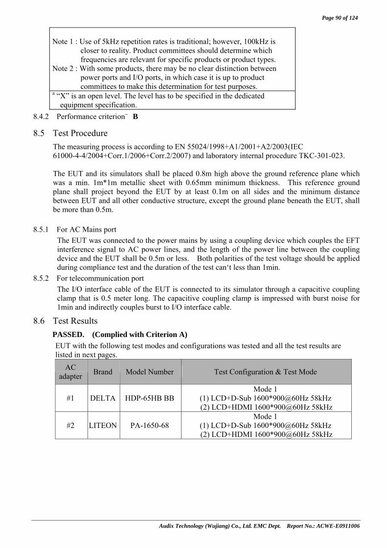
Note 1 : Use of 5kHz repetition rates is traditional; however, 100kHz is
closer to reality. Product committees should determine which frequencies are relevant for specific products or product types.
Note 2 : With some products, there may be no clear distinction between power ports and I/O ports, in which case it is up to product committees to make this determination for test purposes.
a “X” is an open level. The level has to be specified in the dedicated equipment specification.
8.4.2 Performance criterion:B
8.5 Test Procedure The measuring process is according to EN 55024/1998+A1/2001+A2/2003(IEC 61000-4-4/2004+Corr.1/2006+Corr.2/2007) and laboratory internal procedure TKC-301-023. The EUT and its simulators shall be placed 0.8m high above the ground reference plane which was a min. 1m*1m metallic sheet with 0.65mm minimum thickness. This reference ground plane shall project beyond the EUT by at least 0.1m on all sides and the minimum distance between EUT and all other conductive structure, except the ground plane beneath the EUT, shall be more than 0.5m.
8.5.1 For AC Mains port The EUT was connected to the power mains by using a coupling device which couples the EFT interference signal to AC power lines, and the length of the power line between the coupling device and the EUT shall be 0.5m or less. Both polarities of the test voltage should be applied during compliance test and the duration of the test can‘t less than 1min.
8.5.2 For telecommunication port The I/O interface cable of the EUT is connected to its simulator through a capacitive coupling clamp that is 0.5 meter long. The capacitive coupling clamp is impressed with burst noise for 1min and indirectly couples burst to I/O interface cable.
8.6 Test Results PASSED. (Complied with Criterion A) EUT with the following test modes and configurations was tested and all the test results are listed in next pages.
AC adapter Brand Model Number Test Configuration & Test Mode
#1 DELTA HDP-65HB BB Mode 1
(1) LCD+D-Sub 1600*900@60Hz 58kHz (2) LCD+HDMI 1600*900@60Hz 58kHz
#2 LITEON PA-1650-68 Mode 1
(1) LCD+D-Sub 1600*900@60Hz 58kHz (2) LCD+HDMI 1600*900@60Hz 58kHz
Page 91 of 124
Audix Technology (Wujiang) Co., Ltd. EMC Dept. Report No.: ACWE-E0911006
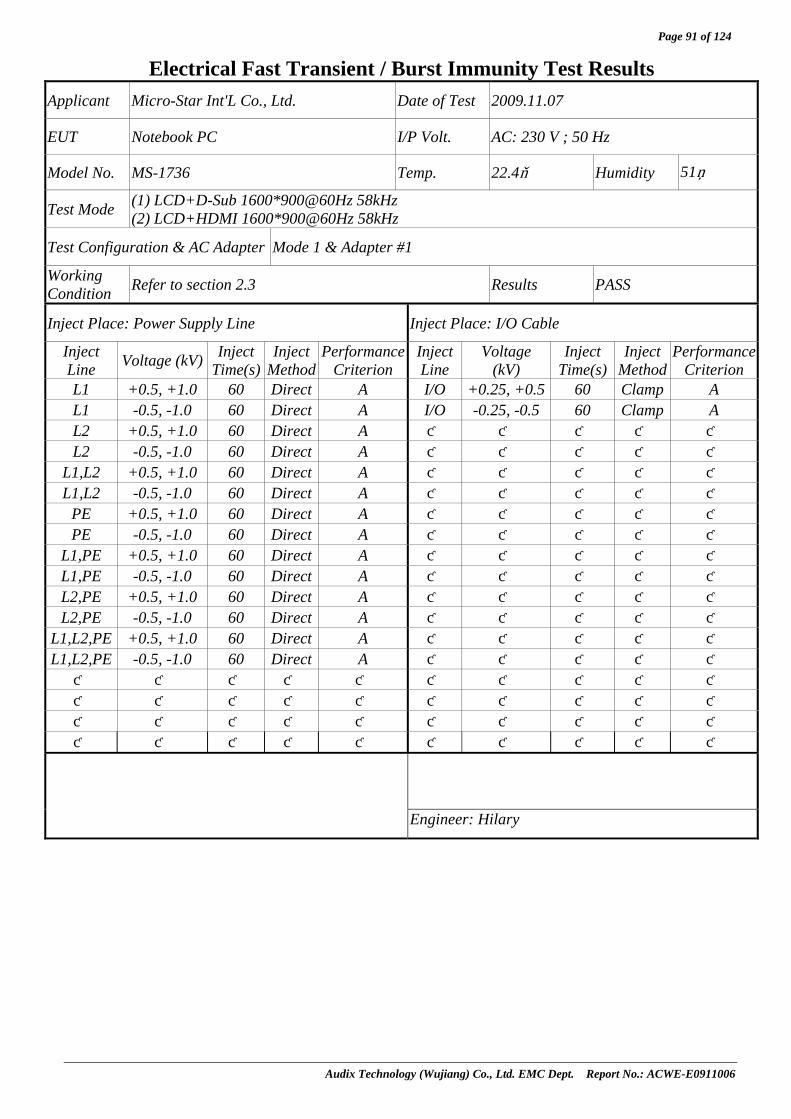
Electrical Fast Transient / Burst Immunity Test Results Applicant Micro-Star Int'L Co., Ltd. Date of Test 2009.11.07
EUT Notebook PC I/P Volt. AC: 230 V ; 50 Hz
Model No. MS-1736 Temp. 22.4 Humidity 51%
Test Mode (1) LCD+D-Sub 1600*900@60Hz 58kHz (2) LCD+HDMI 1600*900@60Hz 58kHz
Test Configuration & AC Adapter Mode 1 & Adapter #1
Working Condition Refer to section 2.3 Results PASS
Inject Place: Power Supply Line Inject Place: I/O Cable
Inject Line Voltage (kV) Inject
Time(s) Inject
Method Performance
Criterion Inject Line
Voltage (kV)
Inject Time(s)
Inject Method
Performance Criterion
L1 +0.5, +1.0 60 Direct A I/O +0.25, +0.5 60 Clamp A L1 -0.5, -1.0 60 Direct A I/O -0.25, -0.5 60 Clamp A L2 +0.5, +1.0 60 Direct A L2 -0.5, -1.0 60 Direct A
L1,L2 +0.5, +1.0 60 Direct A L1,L2 -0.5, -1.0 60 Direct A
PE +0.5, +1.0 60 Direct A PE -0.5, -1.0 60 Direct A
L1,PE +0.5, +1.0 60 Direct A L1,PE -0.5, -1.0 60 Direct A L2,PE +0.5, +1.0 60 Direct A L2,PE -0.5, -1.0 60 Direct A
L1,L2,PE +0.5, +1.0 60 Direct A L1,L2,PE -0.5, -1.0 60 Direct A
Engineer: Hilary

Page 92 of 124
Audix Technology (Wujiang) Co., Ltd. EMC Dept. Report No.: ACWE-E0911006
Electrical Fast Transient / Burst Immunity Test Results Applicant Micro-Star Int'L Co., Ltd. Date of Test 2009.11.07
EUT Notebook PC I/P Volt. AC: 230 V ; 50 Hz
Model No. MS-1736 Temp. 22.4 Humidity 51%
Test Mode (1) LCD+D-Sub 1600*900@60Hz 58kHz (2) LCD+HDMI 1600*900@60Hz 58kHz
Test Configuration & AC Adapter Mode 1 & Adapter #2
Working Condition Refer to section 2.3 Results PASS
Inject Place: Power Supply Line Inject Place: I/O Cable
Inject Line Voltage (kV) Inject
Time(s) Inject
Method Performance
Criterion Inject Line
Voltage (kV)
Inject Time(s)
Inject Method
Performance Criterion
L1 +0.5, +1.0 60 Direct A I/O +0.25, +0.5 60 Clamp A L1 -0.5, -1.0 60 Direct A I/O -0.25, -0.5 60 Clamp A L2 +0.5, +1.0 60 Direct A L2 -0.5, -1.0 60 Direct A
L1,L2 +0.5, +1.0 60 Direct A L1,L2 -0.5, -1.0 60 Direct A
PE +0.5, +1.0 60 Direct A PE -0.5, -1.0 60 Direct A
L1,PE +0.5, +1.0 60 Direct A L1,PE -0.5, -1.0 60 Direct A L2,PE +0.5, +1.0 60 Direct A L2,PE -0.5, -1.0 60 Direct A
L1,L2,PE +0.5, +1.0 60 Direct A L1,L2,PE -0.5, -1.0 60 Direct A
Engineer: Hilary

Page 93 of 124
Audix Technology (Wujiang) Co., Ltd. EMC Dept. Report No.: ACWE-E0911006
9 SURGE IMMUNITY TEST
9.1 Test Equipment Item Type Manufacturer Model No. Serial No. Last Cal. Next Cal.
1. Plus Immunity Test System
Thermo Electron Corp. EMC pro 0604251 2009-03-25 2010-03-24
2. Coupling
Decoupling Network
Thermo Electron Corp.
CM-I/OCD&HS 0604248 2009-08-11 2010-08-10
3. Coupling
Decoupling Network
Thermo Electron Corp. CM-TELCD 0604221 2009-08-11 2010-08-10
9.2 Block Diagram of Test Setup
9.2.1 Block Diagram of connection between EUT and simulators. Same as section 7.2.1.
9.2.2 Test Setup
9.3 Test Standard EN 55024/1998 +A1/2001+A2/2003 【IEC 61000-4-5/2005, Test Level:line to earth - ± 2kV (peak), line to line - ± 1kV(peak),
1.2/50 (8/20) Tr/Thµs.】
9.4 Severity Levels and Performance Criterion
9.4.1 Test Levels
Level Open-circuit test Voltage +/- 10%, kV
1. 0.5
2. 1.0
3. 2.0
4. 4.0
X Special
9.4.2 Performance Criterion: B
Remark: Test generator includes control center、surge combination and coupler.
80cm To AC Power Supply Network
AC LineEUT
Ground Plane
Coupler/ Decoupler
Telecom. Line
Test Generator
TABLE

Page 94 of 124
Audix Technology (Wujiang) Co., Ltd. EMC Dept. Report No.: ACWE-E0911006
9.5 Test Procedure The measuring process is according to EN 55024/1998 +A1/2001+A2/2003 (IEC 61000-4-5/2005) and laboratory internal procedure TKC-301-022.
For AC Mains ports:
9.5.1 Set up the EUT and test generator as shown on section 9.2.1 & 9.2.2.
9.5.2 For line to line coupling mode, provided a 0.5/1kV 1.2/50 μs current surge (at open-circuit condition) and 8/20 μs current surge to EUT selected points.
9.5.3 At least 5 positive and 5 negative (polarity) tests with a Maximum 1/min repetition rate were conducted during test.
9.5.4 Different phase angles were done individually.
9.5.5 Repeat procedure 9.5.2. to 9.5.4. except the open-circuit test voltages 0.5kV/1kV/2kV for line to earth coupling mode test.
9.5.6 Record the EUT Operating situation during compliance test and decide the EUT immunity criterion for above each test.
For Telecommunication ports:
9.5.7 Set up the EUT and test generator as shown on section 9.2.1 & 9.2.2.
9.5.8 For line to line coupling mode, provided a 0.5/1kV 1.2/50 μs current surge (at open-circuit condition) and 8/20 μs current surge to EUT selected points.
9.5.9 At least 5 positive and 5 negative (polarity) tests with a Maximum 1/min repetition rate were conducted during test.
9.5.10 Repeat procedure 9.5.7. to 9.5.9 for line to earth coupling mode test.
9.5.11 Record the EUT Operating situation during compliance test and decide the EUT immunity criterion for above each test.
9.6 Test Results PASSED. (Complied with Criterion A)
EUT with the following test modes and configurations was tested and all the test results are listed in next pages.
AC adapter Brand Model Number Test Configuration & Test Mode
#1 DELTA HDP-65HB BB Mode 1
(1) LCD+D-Sub 1600*900@60Hz 58kHz (2) LCD+HDMI 1600*900@60Hz 58kHz
#2 LITEON PA-1650-68 Mode 1
(1) LCD+D-Sub 1600*900@60Hz 58kHz (2) LCD+HDMI 1600*900@60Hz 58kHz

Page 95 of 124
Audix Technology (Wujiang) Co., Ltd. EMC Dept. Report No.: ACWE-E0911006
Surge Immunity Test Results
Applicant Micro-Star Int'L Co., Ltd. Date of Test 2009.11.07
EUT Notebook PC I/P Volt. AC: 230 V ; 50Hz
Model No. MS-1736 Temp. 22.4 Humidity 51%
Test Mode (1) LCD+D-Sub 1600*900@60Hz 58kHz (2) LCD+HDMI 1600*900@60Hz 58kHz
Test Configuration & AC Adapter Mode 1 & Adapter #1
Working Condition Refer to section 2.3 Results PASS
Input and Output AC Power Port
Location Polarity Phase Angle
No of Pulse Pulse Voltage Performance
Criterion + 0 5 0.5kV, 1.0kV A+ 90 5 0.5kV, 1.0kV A+ 180 5 0.5kV, 1.0kV A+ 270 5 0.5kV ,1.0kV A- 0 5 0.5kV ,1.0kV A- 90 5 0.5kV , 1.0kV A- 180 5 0.5kV , 1.0kV A
L-N
- 270 5 0.5kV , 1.0kV A+ 0 5 0.5kV, 1.0kV , 2.0kV A+ 90 5 0.5kV, 1.0kV , 2.0kV A+ 180 5 0.5kV, 1.0kV , 2.0kV A+ 270 5 0.5kV, 1.0kV , 2.0kV A- 0 5 0.5kV, 1.0kV , 2.0kV A- 90 5 0.5kV, 1.0kV , 2.0kV A- 180 5 0.5kV, 1.0kV , 2.0kV A
L-PE
- 270 5 0.5kV, 1.0kV , 2.0kV A+ 0 5 0.5kV, 1.0kV , 2.0kV A+ 90 5 0.5kV, 1.0kV , 2.0kV A+ 180 5 0.5kV, 1.0kV , 2.0kV A+ 270 5 0.5kV, 1.0kV , 2.0kV A- 0 5 0.5kV, 1.0kV , 2.0kV A- 90 5 0.5kV, 1.0kV , 2.0kV A- 180 5 0.5kV, 1.0kV , 2.0kV A
N-PE
- 270 5 0.5kV, 1.0kV , 2.0kV A+ 0 5 0.5kV, 1.0kV , 2.0kV A+ 90 5 0.5kV, 1.0kV , 2.0kV A+ 180 5 0.5kV, 1.0kV , 2.0kV A+ 270 5 0.5kV, 1.0kV , 2.0kV A- 0 5 0.5kV, 1.0kV , 2.0kV A- 90 5 0.5kV, 1.0kV , 2.0kV A- 180 5 0.5kV, 1.0kV , 2.0kV A
L, N-PE
- 270 5 0.5kV, 1.0kV , 2.0kV A
Engineer: Hilary

Page 96 of 124
Audix Technology (Wujiang) Co., Ltd. EMC Dept. Report No.: ACWE-E0911006
Surge Immunity Test Results Applicant Micro-Star Int'L Co., Ltd. Date of Test 2009.11.07
EUT Notebook PC I/P Volt. AC: 230 V ; 50Hz
Model No. MS-1736 Temp. 22.4 Humidity 51%
Test Mode (1) LCD+D-Sub 1600*900@60Hz 58kHz (2) LCD+HDMI 1600*900@60Hz 58kHz
Test Configuration & AC Adapter Mode 1 & Adapter #1
Working Condition Refer to section 2.3 Results PASS
Telecom Line Coupling No of Performance Line Polarity Pulse
Pulse Voltage Criterion
+ 5 0.5kV,1kV N/A T1 - 5 0.5kV,1kV N/A
+ 5 0.5kV,1kV N/A R1 - 5 0.5kV,1kV N/A
+ 5 0.5kV,1kV N/A T2 - 5 0.5kV,1kV N/A
+ 5 0.5kV,1kV N/A R2 - 5 0.5kV,1kV N/A
+ 5 0.5kV,1kV N/A T1, R1 - 5 0.5kV,1kV N/A
+ 5 0.5kV,1kV N/A T2, R2 - 5 0.5kV,1kV N/A
+ 5 0.5kV,1kV N/A T1, R1, T2, R2 - 5 0.5kV,1kV N/A
[ ]DC Input and Output Power Port ⁄[ˇ ]I/O Signal Cable
No of Performance Location Polarity
Pulse Pulse Voltage
Criterion Differential + 5 0.5kV,1kV N/A
Mode - 5 0.5kV,1kV N/A
Common + 5 0.5kV,1kV A
Mode - 5 0.5kV,1kV A
Engineer :Hilary

Page 97 of 124
Audix Technology (Wujiang) Co., Ltd. EMC Dept. Report No.: ACWE-E0911006
Surge Immunity Test Results
Applicant Micro-Star Int'L Co., Ltd. Date of Test 2009.11.07
EUT Notebook PC I/P Volt. AC: 230 V ; 50Hz
Model No. MS-1736 Temp. 22.4 Humidity 51%
Test Mode (1) LCD+D-Sub 1600*900@60Hz 58kHz (2) LCD+HDMI 1600*900@60Hz 58kHz
Test Configuration & AC Adapter Mode 1 & Adapter #2
Working Condition Refer to section 2.3 Results PASS
Input and Output AC Power Port
Location Polarity Phase Angle
No of Pulse Pulse Voltage Performance
Criterion + 0 5 0.5kV, 1.0kV A+ 90 5 0.5kV, 1.0kV A+ 180 5 0.5kV, 1.0kV A+ 270 5 0.5kV ,1.0kV A- 0 5 0.5kV ,1.0kV A- 90 5 0.5kV , 1.0kV A- 180 5 0.5kV , 1.0kV A
L-N
- 270 5 0.5kV , 1.0kV A+ 0 5 0.5kV, 1.0kV , 2.0kV A+ 90 5 0.5kV, 1.0kV , 2.0kV A+ 180 5 0.5kV, 1.0kV , 2.0kV A+ 270 5 0.5kV, 1.0kV , 2.0kV A- 0 5 0.5kV, 1.0kV , 2.0kV A- 90 5 0.5kV, 1.0kV , 2.0kV A- 180 5 0.5kV, 1.0kV , 2.0kV A
L-PE
- 270 5 0.5kV, 1.0kV , 2.0kV A+ 0 5 0.5kV, 1.0kV , 2.0kV A+ 90 5 0.5kV, 1.0kV , 2.0kV A+ 180 5 0.5kV, 1.0kV , 2.0kV A+ 270 5 0.5kV, 1.0kV , 2.0kV A- 0 5 0.5kV, 1.0kV , 2.0kV A- 90 5 0.5kV, 1.0kV , 2.0kV A- 180 5 0.5kV, 1.0kV , 2.0kV A
N-PE
- 270 5 0.5kV, 1.0kV , 2.0kV A+ 0 5 0.5kV, 1.0kV , 2.0kV A+ 90 5 0.5kV, 1.0kV , 2.0kV A+ 180 5 0.5kV, 1.0kV , 2.0kV A+ 270 5 0.5kV, 1.0kV , 2.0kV A- 0 5 0.5kV, 1.0kV , 2.0kV A- 90 5 0.5kV, 1.0kV , 2.0kV A- 180 5 0.5kV, 1.0kV , 2.0kV A
L, N-PE
- 270 5 0.5kV, 1.0kV , 2.0kV A
Engineer: Hilary

Page 98 of 124
Audix Technology (Wujiang) Co., Ltd. EMC Dept. Report No.: ACWE-E0911006
Surge Immunity Test Results Applicant Micro-Star Int'L Co., Ltd. Date of Test 2009.11.07
EUT Notebook PC I/P Volt. AC: 230 V ; 50Hz
Model No. MS-1736 Temp. 22.4 Humidity 51%
Test Mode (1) LCD+D-Sub 1600*900@60Hz 58kHz (2) LCD+HDMI 1600*900@60Hz 58kHz
Test Configuration & AC Adapter Mode 1 & Adapter #2
Working Condition Refer to section 2.3 Results PASS
Telecom Line Coupling No of Performance Line Polarity Pulse
Pulse Voltage Criterion
+ 5 0.5kV,1kV N/A T1 - 5 0.5kV,1kV N/A
+ 5 0.5kV,1kV N/A R1 - 5 0.5kV,1kV N/A
+ 5 0.5kV,1kV N/A T2 - 5 0.5kV,1kV N/A
+ 5 0.5kV,1kV N/A R2 - 5 0.5kV,1kV N/A
+ 5 0.5kV,1kV N/A T1, R1 - 5 0.5kV,1kV N/A
+ 5 0.5kV,1kV N/A T2, R2 - 5 0.5kV,1kV N/A
+ 5 0.5kV,1kV N/A T1, R1, T2, R2 - 5 0.5kV,1kV N/A
[ ]DC Input and Output Power Port ⁄[ˇ ]I/O Signal Cable
No of Performance Location Polarity
Pulse Pulse Voltage
Criterion Differential + 5 0.5kV,1kV N/A
Mode - 5 0.5kV,1kV N/A
Common + 5 0.5kV,1kV A
Mode - 5 0.5kV,1kV A
Engineer :Hilary

Page 99 of 124
Audix Technology (Wujiang) Co., Ltd. EMC Dept. Report No.: ACWE-E0911006
10 CONDUCTED DISTURBANCE IMMUNITY TEST
10.1 Test Equipment Item Type Manufacturer Model No. Serial No. Last Cal. Next Cal. 1. Signal Generator Agilent 8648C 3847M01438 2009-03-25 2010-03-242. Power Amplifier AR KAW 2180 10088-2 NCR NCR 3. Attenuator Agilent 8491B MY39262365 2009-01-07 2010-01-064. CDN-M2 FCC FCC-801-M2-25A 6041 NCR NCR 5. CDN-M3 FCC FCC-801-M3-25A 6042 2009-03-25 2010-03-24
6. Decoupling Network FCC F-203I-23MM-DCN 196 NCR NCR
7. EM Injection Clamp FCC F-203I-03MM 503 2009-03-25 2010-03-24
NCR: Non-Calibration Remark
10.2 Block Diagram of Test Setup
10.2.1 Block Diagram of connection between EUT and simulators.
Same as Section 7.2.1.
10.2.2 Common Mode Test Setup
EUT AC SourceCDN
Signal Generator
Personal Computer Control System
Ground Reference support
0.1m
Power Amplifier Attenuator
10.2.3 EM Clamp Mode Test Setup
EUTCDN
Signal Generator
Personal Computer Control System
Ground Reference support
Power Amplifier
50Ω
EM InjectionClamp
AE CDN
50Ω
0.1m0.1m
0.1m < L <0.3m
DCN
Attenuator
10.3 Test Standard
EN 55024/1998+A1/2001 +A2/2003 【IEC 61000-4-6/2008, Severity Level:0.15-80MHz, 3V, 80%AM (1kHz)】

Page 100 of 124
Audix Technology (Wujiang) Co., Ltd. EMC Dept. Report No.: ACWE-E0911006
10.4 Severity Levels and Performance Criterion
10.4.1 Severity levels Frequency range 0.15MHz - 80MHz
Voltage level (e.m.f.) Level U0
dB(µV) U0 V
1. 120 1 2. 130 3 3. 140 10 Xa Special
a X is an open level. 10.4.2 Performance criterion:A
10.5 Test Procedure The measuring process is according to EN 55024/1998+A1/2001 +A2/2003(IEC 61000-4-6/2008) and laboratory internal procedure TKC-301-027. For AC Mains port
10.5.1 Set up the EUT, CDN and test generators as shown on section 10.2.2.
10.5.2 The EUT and supporting equipment were placed on an insulating support 0.1m high above a ground reference plane. CDN (coupling and decoupling device) was placed on the ground plane making contact with it at about 0.1-0.3m from EUT. Cables between CDN and EUT were as short as possible.
10.5.3 The disturbance signal described below was injected to EUT through CDN.
10.5.4 The EUT operates within its operational mode(s) under intended climatic conditions after power on.
10.5.5 The frequency range was swept from 150 kHz to 80MHz using 3V signal level, and with the disturbance signal 80% amplitude modulated with a 1 kHz sine wave.
10.5.6 The rate of sweep shall not exceed 1.5*10^3decades/s. Where the frequency was swept incrementally, the step size shall not exceed 1% of the start and thereafter 1% of the preceding frequency value.
10.5.7 Recording the EUT Operating situation during compliance testing and decide the EUT immunity criterion. For Telecommunication Port
10.5.8 Set up the EUT, EM Injection Clamp and test generators as shown on section 10.2.3.
10.5.9 The EUT and supporting equipment were placed on an insulating support 0.1m high above a ground reference plane. EM Injection Clamp (coupling and decoupling device) was placed on the ground plane making contact with it at about 0.1-0.3m from EUT. Cables between CDN and EUT were as short as possible.
10.5.10 The DCN was placed on between AE and EUT, the EUT and AE of power through CDN, CDN terminated with 50Ω at the RF disturbance input port.
10.5.11 The disturbance signal described below was injected to EUT though EM Injection Clamp.
10.5.12 Repeat above procedure from 10.5.8 to 10.5.11.

Page 101 of 124
Audix Technology (Wujiang) Co., Ltd. EMC Dept. Report No.: ACWE-E0911006
10.6 Test Results PASSED. (Complied with Criterion A) EUT with the following test modes and configurations was tested and all the test results are listed in next pages.
AC adapter Brand Model Number Test Configuration & Test Mode
#1 DELTA HDP-65HB BB Mode 1
(1) LCD+D-Sub 1600*900@60Hz 58kHz (2) LCD+HDMI 1600*900@60Hz 58kHz
#2 LITEON PA-1650-68 Mode 1
(1) LCD+D-Sub 1600*900@60Hz 58kHz (2) LCD+HDMI 1600*900@60Hz 58kHz

Page 102 of 124
Audix Technology (Wujiang) Co., Ltd. EMC Dept. Report No.: ACWE-E0911006
Inject Currents Immunity Test Results Applicant Micro-Star Int'L Co., Ltd. Date of Test 2009.11.06
EUT Notebook PC I/P Volt. AC: 230V ; 50Hz
Model No. MS-1736 Temp. 19.9 Humidity 56%
Test Mode (1) LCD+D-Sub 1600*900@60Hz 58kHz (2) LCD+HDMI 1600*900@60Hz 58kHz
Test Configuration & AC Adapter Mode 1 & Adapter #1
Working Condition Refer to section 2.3 Results PASS
Frequency Range (MHz) Inject Position Strength Performance
Criterion Remark
0.15MHz~80MHz Main 3V A
0.15MHz~80MHz I/O 3V A
I/O:RJ45 Port
Engineer : Joecy Ma
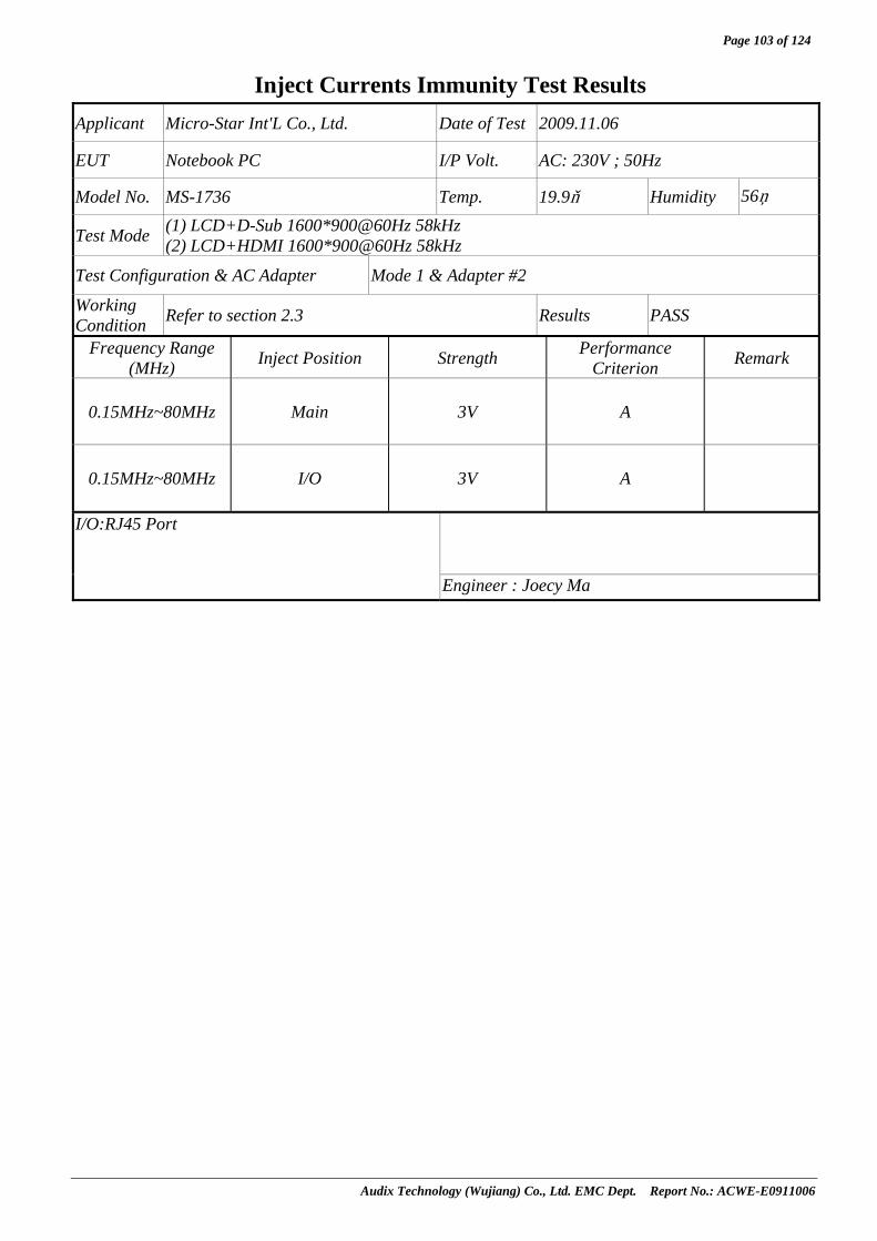
Page 103 of 124
Audix Technology (Wujiang) Co., Ltd. EMC Dept. Report No.: ACWE-E0911006
Inject Currents Immunity Test Results Applicant Micro-Star Int'L Co., Ltd. Date of Test 2009.11.06
EUT Notebook PC I/P Volt. AC: 230V ; 50Hz
Model No. MS-1736 Temp. 19.9 Humidity 56%
Test Mode (1) LCD+D-Sub 1600*900@60Hz 58kHz (2) LCD+HDMI 1600*900@60Hz 58kHz
Test Configuration & AC Adapter Mode 1 & Adapter #2
Working Condition Refer to section 2.3 Results PASS
Frequency Range (MHz) Inject Position Strength Performance
Criterion Remark
0.15MHz~80MHz Main 3V A
0.15MHz~80MHz I/O 3V A
I/O:RJ45 Port
Engineer : Joecy Ma

Page 104 of 124
Audix Technology (Wujiang) Co., Ltd. EMC Dept. Report No.: ACWE-E0911006
11 POWER FREQUENCY MAGNETIC FIELD IMMUNITY TEST
11.1 Test Equipment Item Type Manufacturer Model No. Serial No. Last Cal. Next Cal.
1. Plus Immunity Test System KEYTEK EMC pro 0604251 2009-03-25 2010-03-24
2. Magnetic Field Immunity Loop FCC F-1000-4-8-/
9/10-L-1M 06008 NCR NCR
NCR: Non-Calibration Mark
11.2 Block Diagram of Test Setup
11.2.1 Block Diagram of connection between EUT and simulators. Same as section 7.2.1.
11.2.2 Test Setup
Test Generator
Induction CoilEUT
Non-Conductive Table
11.3 Test Standard
EN 55024/1998+A1/2001+A2/2003 【IEC 61000-4-8/2001, Test Level: 50Hz, 1A/m】
11.4 Severity Levels and Performance Criterion
11.4.1 Severity level
Level Magnetic Field Strength Continuous Field A/m 1. 1 2. 3 3. 10 4. 30 5. 100 X Special
11.4.2 Performance criterion:A

Page 105 of 124
Audix Technology (Wujiang) Co., Ltd. EMC Dept. Report No.: ACWE-E0911006
11.5 Test Procedure The measuring process is according to EN 55024/1998+A1/2001+A2/2003 (IEC 61000-4-8/2001) and laboratory internal procedure TKC-301-012. The EUT was placed on 1m high table that above the ground reference plane which is the min. size 1m x 1m and 0.65mm thickness metallic. And subjected to the test magnetic field by using the induction coil of standard dimensions (1m x 1m). The induction coil rotated by 90 degrees in order to expose the EUT to the test field with different orientations. All cables of EUT exposed to magnetic field for 1m of their length.
11.6 Test Results PASSED. (Complied with Criterion A) EUT with the following test modes and configurations was tested and all the test results are listed in next pages.
AC adapter Brand Model Number Test Configuration & Test Mode
#1 DELTA HDP-65HB BB Mode 1
(1) LCD+D-Sub 1600*900@60Hz 58kHz (2) LCD+HDMI 1600*900@60Hz 58kHz
#2 LITEON PA-1650-68 Mode 1
(1) LCD+D-Sub 1600*900@60Hz 58kHz (2) LCD+HDMI 1600*900@60Hz 58kHz

Page 106 of 124
Audix Technology (Wujiang) Co., Ltd. EMC Dept. Report No.: ACWE-E0911006
Power Frequency Magnetic Field Immunity Test Results Applicant Micro-Star Int'L Co., Ltd. Date of Test 2009.11.07
EUT Notebook PC I/P Volt. AC: 230 V ; 50 Hz
Model No. MS-1736 Temp. 22.4 Humidity 51%
Test Mode (1) LCD+D-Sub 1600*900@60Hz 58kHz (2) LCD+HDMI 1600*900@60Hz 58kHz
Test Configuration & AC Adapter Mode 1 & Adapter #1
Working Condition Refer to section 2.3 Results PASS
Power Frequency Magnetic Field Testing Duration Coil Orientation Performance Criterion Remark
50Hz,1A/m 1 Minute X-axis A
50Hz,1A/m 1 Minute Y-axis A
50Hz,1A/m 1 Minute Z-axis A
Engineer: Hilary

Page 107 of 124
Audix Technology (Wujiang) Co., Ltd. EMC Dept. Report No.: ACWE-E0911006
Power Frequency Magnetic Field Immunity Test Results Applicant Micro-Star Int'L Co., Ltd. Date of Test 2009.11.07
EUT Notebook PC I/P Volt. AC: 230 V ; 50 Hz
Model No. MS-1736 Temp. 22.4 Humidity 51%
Test Mode (1) LCD+D-Sub 1600*900@60Hz 58kHz (2) LCD+HDMI 1600*900@60Hz 58kHz
Test Configuration & AC Adapter Mode 1 & Adapter #2
Working Condition Refer to section 2.3 Results PASS
Power Frequency Magnetic Field Testing Duration Coil Orientation Performance Criterion Remark
50Hz,1A/m 1 Minute X-axis A
50Hz,1A/m 1 Minute Y-axis A
50Hz,1A/m 1 Minute Z-axis A
Engineer: Hilary

Page 108 of 124
Audix Technology (Wujiang) Co., Ltd. EMC Dept. Report No.: ACWE-E0911006
12 VOLTAGE DIPS AND INTERRUPTIONS IMMUNITY TEST
12.1 Test Equipment Item Type Manufacturer Model No. Serial No. Last Cal. Next Cal.
1. Plus Immunity TestSystem KEYTEK EMC pro 0604251 2009-03-25 2010-03-24
12.2 Block Diagram of Test Setup
12.2.1 Block Diagram of connection between EUT and simulators. Same as section 7.2.1.
12.2.2 Test Setup
12.3 Test Standard EN 55024/1998 +A1/2001 +A2/2003 【IEC 61000-4-11/2004, Severity Level:Voltage dips : Voltage interruptions >95% reduction: 250 periods; Dips 30% reduction: 25periods; >95% reduction: 0.5period】
12.4 Severity Levels and Performance Criterion
12.4.1 Preferred severity levels and durations for voltage dips
Classa Test level and durations for voltage dips (ts) (50Hz/60Hz)
Class 1 Case-by-case according to the equipment requirements
Class 2 0% during ½ cycle
0% during 1 cycle
70% during 25/30c cycles
Class 3 0% during ½ cycle
0% during 1 cycle
40% during 10/12c cycles
70% during 25/30c cycles
80% during 250/300c cycles
Class Xb X X X X X a Classes as per IEC 61000-2-4. b To be defined by product committee. For equipment connected directly or indirectly
to the public network, the levels must not be less severe than Class 2. c “25/30 cycles” means “25 cycles for 50Hz test” and “30 cycles for 60Hz test”.
EUT
AC Line
O/P
To AC Power Supply Network
Plus Immunity Test System
I/P

Page 109 of 124
Audix Technology (Wujiang) Co., Ltd. EMC Dept. Report No.: ACWE-E0911006
12.4.2 Preferred severity levels and durations for short interruptions
Classa Test level and durations for short interruptions (ts) (50Hz/60Hz)
Class 1 Case-by-case according to the equipment requirements
Class 2 0% during 250/300c cycles
Class 3 80% during 250/300c cycles
Class Xb X a Classes as per IEC 61000-2-4. b To be defined by product committee. For equipment connected directly or indirectly
to the public network, the levels must not be less severe than Class 2. c “250/300 cycles” means “250 cycles for 50Hz test” and “300 cycles for 60Hz test”.
12.4.3 Performance criterion: 1) Voltage dips >95% reduction performance criterion B. 2) Voltage dips 30% reduction performance criterion C. 3) Voltage interruption >95% reduction performance criterion C.
12.5 Test Procedure The measuring process is according to EN 55024/1998 +A1/2001 +A2/2003 (IEC 61000-4-11/2004) and laboratory internal procedure TKC-301-003.
12.5.1 Set up the EUT and test generator as shown on section 12.2.
12.5.2 The interruption was introduced at selected phase angles with specified duration. There was a 10s minimum interval between each test event.
12.5.3 After each test a full functional check was performed before the next test.
12.5.4 Repeat procedures 12.5.2. & 12.5.3. for voltage dips, only the test level and duration was changed.
12.5.5 Record any degradation of performance.
12.6 Test Results PASSED. (Voltage interruptions complied with criterion B, Voltage dips Complied with criterion A) EUT with the following test modes and configurations was tested and all the test results are listed in next pages.
AC adapter Brand Model Number Test Configuration & Test Mode
#1 DELTA HDP-65HB BB Mode 1
(1) LCD+D-Sub 1600*900@60Hz 58kHz (2) LCD+HDMI 1600*900@60Hz 58kHz
#2 LITEON PA-1650-68 Mode 1
(1) LCD+D-Sub 1600*900@60Hz 58kHz (2) LCD+HDMI 1600*900@60Hz 58kHz

Page 110 of 124
Audix Technology (Wujiang) Co., Ltd. EMC Dept. Report No.: ACWE-E0911006
Voltage Dips and Interruptions Immunity Test Results Applicant Micro-Star Int'L Co., Ltd. Date of Test 2009.11.07
EUT Notebook PC I/P Volt. AC: 230 V ; 50 Hz
Model No. MS-1736 Temp. 22.4 Humidity 51%
Test Mode (1) NB+D-Sub 1600*900@60Hz 58kHz (2) NB+HDMI 1600*900@60Hz 58kHz
Test Configuration & AC Adapter Mode 1 & Adapter #1
Working Condition Refer to section 2.3 Results PASS
Type of Test
Test Voltage Phase Angle % Reduction Period
PerformanceCriterion
0 >95% 250 B 45 >95% 250 B 90 >95% 250 B 135 >95% 250 B 180 >95% 250 B 225 >95% 250 B 270 >95% 250 B
Voltage Interruption 230
315 >95% 250 B 0 30% 25 A 45 30% 25 A 90 30% 25 A 135 30% 25 A 180 30% 25 A 225 30% 25 A 270 30% 25 A
230
315 30% 25 A 0 >95% 0.5 A 45 >95% 0.5 A 90 >95% 0.5 A 135 >95% 0.5 A 180 >95% 0.5 A 225 >95% 0.5 A 270 >95% 0.5 A
Voltage Dips
230
315 >95% 0.5 A
Note: The performance criterion “B” means the power supply to the EUT turned off during the test, but it can recover by itself during the test interval.
Engineer :Hilary
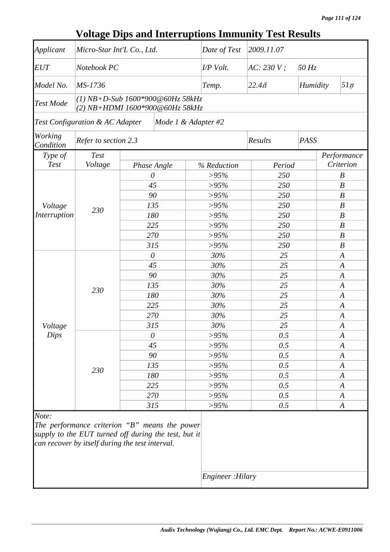
Page 111 of 124
Audix Technology (Wujiang) Co., Ltd. EMC Dept. Report No.: ACWE-E0911006
Voltage Dips and Interruptions Immunity Test Results Applicant Micro-Star Int'L Co., Ltd. Date of Test 2009.11.07
EUT Notebook PC I/P Volt. AC: 230 V ; 50 Hz
Model No. MS-1736 Temp. 22.4 Humidity 51%
Test Mode (1) NB+D-Sub 1600*900@60Hz 58kHz (2) NB+HDMI 1600*900@60Hz 58kHz
Test Configuration & AC Adapter Mode 1 & Adapter #2
Working Condition Refer to section 2.3 Results PASS
Type of Test
Test Voltage Phase Angle % Reduction Period
PerformanceCriterion
0 >95% 250 B 45 >95% 250 B 90 >95% 250 B 135 >95% 250 B 180 >95% 250 B 225 >95% 250 B 270 >95% 250 B
Voltage Interruption 230
315 >95% 250 B 0 30% 25 A 45 30% 25 A 90 30% 25 A 135 30% 25 A 180 30% 25 A 225 30% 25 A 270 30% 25 A
230
315 30% 25 A 0 >95% 0.5 A 45 >95% 0.5 A 90 >95% 0.5 A 135 >95% 0.5 A 180 >95% 0.5 A 225 >95% 0.5 A 270 >95% 0.5 A
Voltage Dips
230
315 >95% 0.5 A
Note: The performance criterion “B” means the power supply to the EUT turned off during the test, but it can recover by itself during the test interval.
Engineer :Hilary

Page 112 of 124
Audix Technology (Wujiang) Co., Ltd. EMC Dept. Report No.: ACWE-E0911006
13 PHOTOGRAPHS
13.1 Photos of Conducted Disturbance Measurement
Front View of Conducted Measurement for AC mains port
Side View of Conducted Measurement for AC mains port
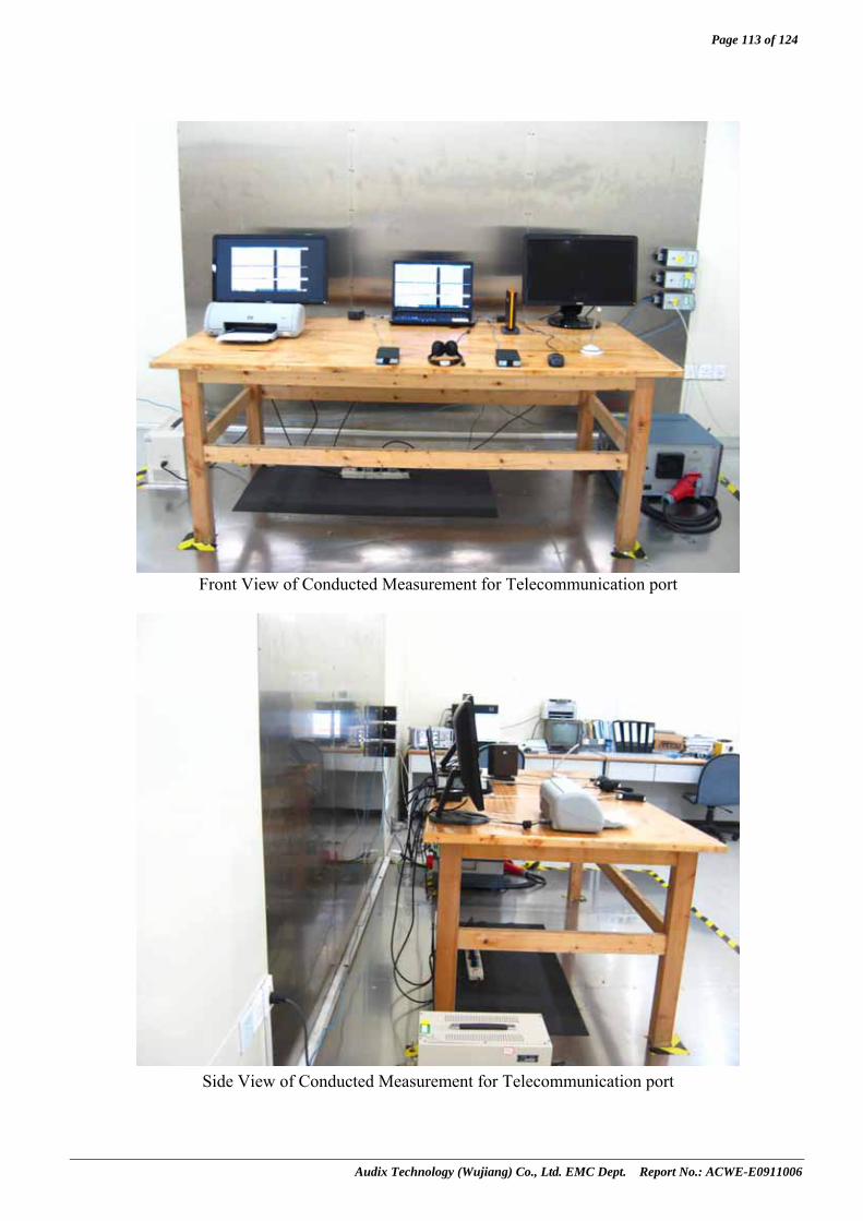
Page 113 of 124
Audix Technology (Wujiang) Co., Ltd. EMC Dept. Report No.: ACWE-E0911006
Front View of Conducted Measurement for Telecommunication port
Side View of Conducted Measurement for Telecommunication port

Page 114 of 124
Audix Technology (Wujiang) Co., Ltd. EMC Dept. Report No.: ACWE-E0911006
13.2 Photos of Radiated Disturbance Measurement For 30MHz~1GHz (At No.1 10m Semi-Anechioc Chambera)
Front View of Radiated Disturbance Measurement
Back View of Radiated Disturbance Measurement
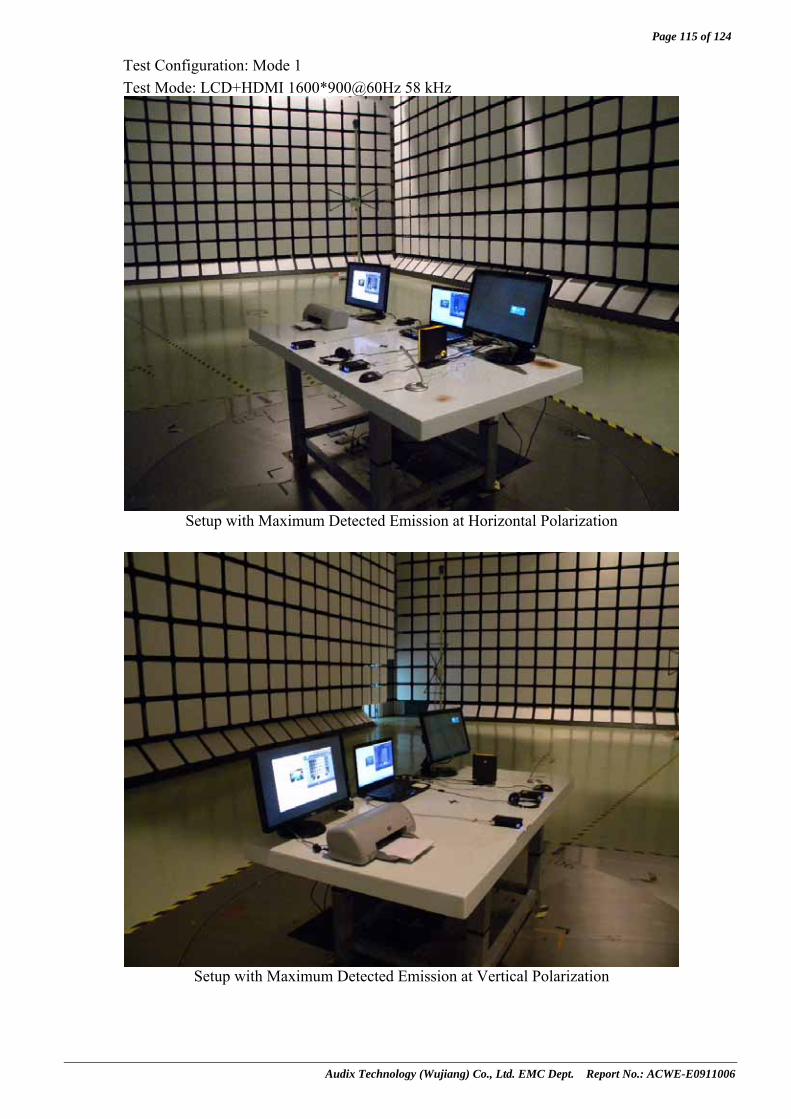
Page 115 of 124
Audix Technology (Wujiang) Co., Ltd. EMC Dept. Report No.: ACWE-E0911006
Test Configuration: Mode 1 Test Mode: LCD+HDMI 1600*900@60Hz 58 kHz
Setup with Maximum Detected Emission at Horizontal Polarization
Setup with Maximum Detected Emission at Vertical Polarization

Page 116 of 124
Audix Technology (Wujiang) Co., Ltd. EMC Dept. Report No.: ACWE-E0911006
For 1GHz~6GHz (At 3m Semi-Anechioc Chambera)
Front View of Radiated Disturbance Measurement
Back View of Radiated Disturbance Measurement

Page 117 of 124
Audix Technology (Wujiang) Co., Ltd. EMC Dept. Report No.: ACWE-E0911006
13.3 Photos of Harmonic & Flicker Measurement
13.4 Photos of Electrostatic Discharge Immunity Test
Air Discharge

Page 118 of 124
Audix Technology (Wujiang) Co., Ltd. EMC Dept. Report No.: ACWE-E0911006
VCP & HCP
13.5 Photos of RF Field Strength Immunity Test
Front View of R/S Test

Page 119 of 124
Audix Technology (Wujiang) Co., Ltd. EMC Dept. Report No.: ACWE-E0911006
Back View of R/S Test
13.6 Photos of Electrical Fast Transient/Burst Immunity Test
For AC Mains port

Page 120 of 124
Audix Technology (Wujiang) Co., Ltd. EMC Dept. Report No.: ACWE-E0911006
For Telecommunication port
13.7 Photos of Surge Immunity Test
For AC Mains port

Page 121 of 124
Audix Technology (Wujiang) Co., Ltd. EMC Dept. Report No.: ACWE-E0911006
For Telecommunication port
13.8 Photos of Conducted Disturbance Immunity Test
For AC Mains port

Page 122 of 124
Audix Technology (Wujiang) Co., Ltd. EMC Dept. Report No.: ACWE-E0911006
For Telecommunication port
13.9 Photos of Power Frequency Magnetic Field Immunity Test

Page 123 of 124
Audix Technology (Wujiang) Co., Ltd. EMC Dept. Report No.: ACWE-E0911006
13.10 Photos of Voltage Dips and Interruptions Immunity Test
13.11 Photos of host PC for RJ45 ping test

Page 124 of 124
Audix Technology (Wujiang) Co., Ltd. EMC Dept. Report No.: ACWE-E0911006
13.12 Photos of WALAN& Bluetooth function test
APPENDIX I
Audix Technology (Wujiang) Co., Ltd. EMC Dept. Report No.: ACWE-E0911006
APPENDIX I Pre-scan data of radiated disturbance measurement

APPENDIX I-Page 1 of 8
Audix Technology (Wujiang) Co., Ltd. EMC Dept. Report No.: ACWE-E0911006

APPENDIX I-Page 2 of 8
Audix Technology (Wujiang) Co., Ltd. EMC Dept. Report No.: ACWE-E0911006

APPENDIX I-Page 3 of 8
Audix Technology (Wujiang) Co., Ltd. EMC Dept. Report No.: ACWE-E0911006
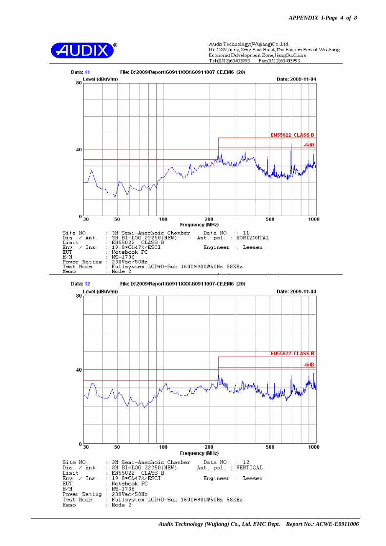
APPENDIX I-Page 4 of 8
Audix Technology (Wujiang) Co., Ltd. EMC Dept. Report No.: ACWE-E0911006

APPENDIX I-Page 5 of 8
Audix Technology (Wujiang) Co., Ltd. EMC Dept. Report No.: ACWE-E0911006

APPENDIX I-Page 6 of 8
Audix Technology (Wujiang) Co., Ltd. EMC Dept. Report No.: ACWE-E0911006

APPENDIX I-Page 7 of 8
Audix Technology (Wujiang) Co., Ltd. EMC Dept. Report No.: ACWE-E0911006
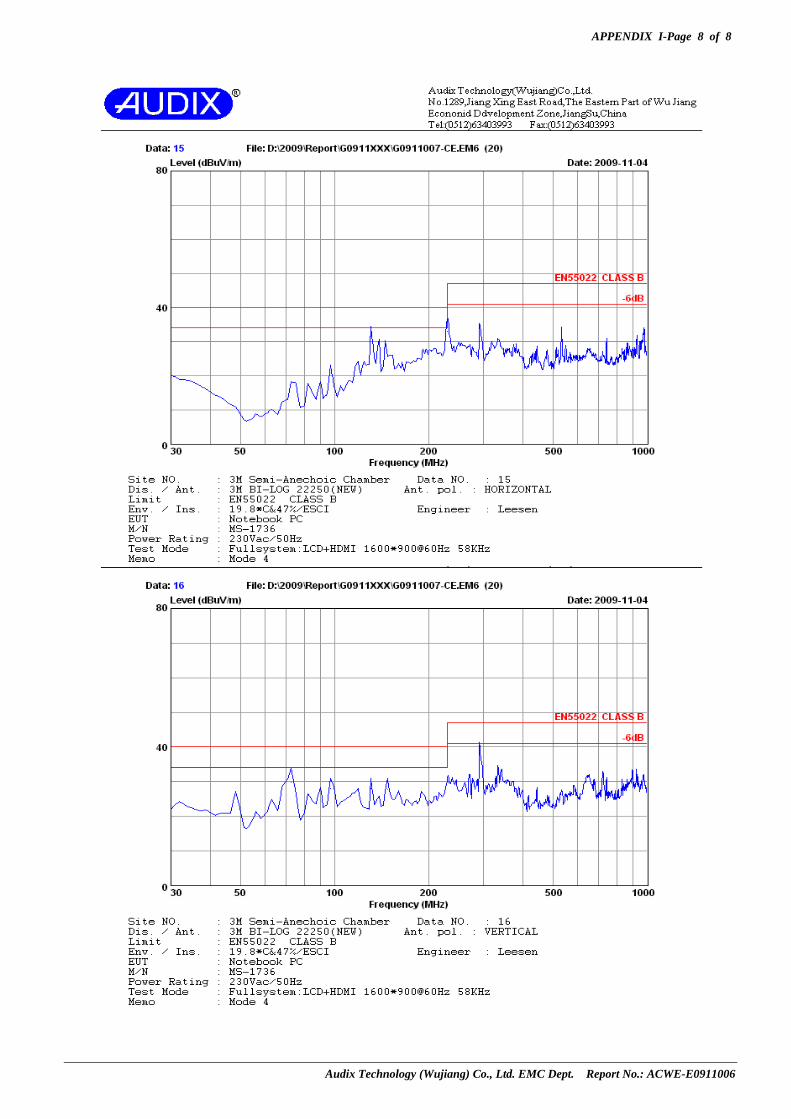
APPENDIX I-Page 8 of 8
Audix Technology (Wujiang) Co., Ltd. EMC Dept. Report No.: ACWE-E0911006

APPENDIX II
Audix Technology (Wujiang) Co., Ltd. EMC Dept. Report No.: ACWE-E0911006
APPENDIX II
Photos of EUT

APPENDIX II-Page 1 of 63
Audix Technology (Wujiang) Co., Ltd. EMC Dept. Report No.: ACWE-E0911006
Figure 1 General Appearance (Top View)
Figure2
General Appearance (Bottom View)
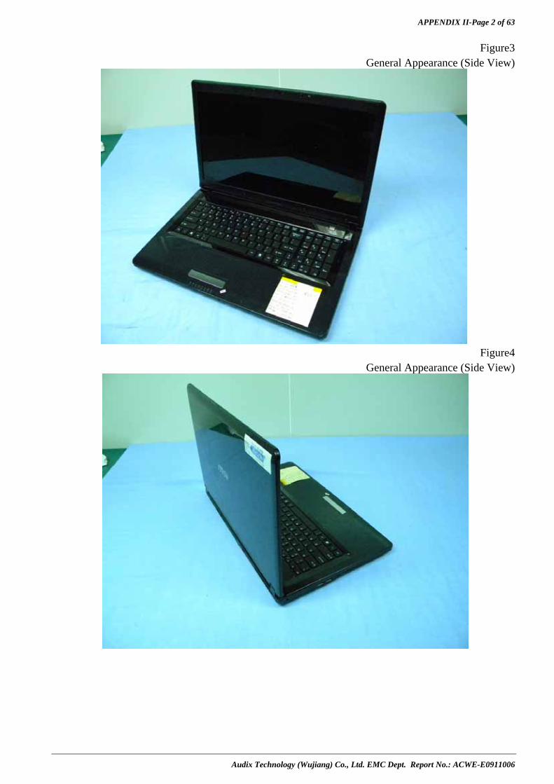
APPENDIX II-Page 2 of 63
Audix Technology (Wujiang) Co., Ltd. EMC Dept. Report No.: ACWE-E0911006
Figure3 General Appearance (Side View)
Figure4
General Appearance (Side View)

APPENDIX II-Page 3 of 63
Audix Technology (Wujiang) Co., Ltd. EMC Dept. Report No.: ACWE-E0911006
Figure5 General Appearance (Back View, I/O Ports)
Figure6
General Appearance (Left Side, I/O Ports)

APPENDIX II-Page 4 of 63
Audix Technology (Wujiang) Co., Ltd. EMC Dept. Report No.: ACWE-E0911006
Figure7 General Appearance (Right Side, I/O Ports)
Figure8
General Appearance (Battery Remove)

APPENDIX II-Page 5 of 63
Audix Technology (Wujiang) Co., Ltd. EMC Dept. Report No.: ACWE-E0911006
Figure9 Battery (BTY-L75/91NMS17LF6SU1,back View)
Figure10
Battery (BTY-L74/91NMS17LD4SU1,Front View)

APPENDIX II-Page 6 of 63
Audix Technology (Wujiang) Co., Ltd. EMC Dept. Report No.: ACWE-E0911006
Figure11 Battery (BTY-L74/91NMS17LD4SU1,Back View)
Figure12
Cover Remove

APPENDIX II-Page 7 of 63
Audix Technology (Wujiang) Co., Ltd. EMC Dept. Report No.: ACWE-E0911006
Figure13 HDD Remove
Figure14
HDD (TOSHIBA/MK5055GSX/500GB,Front View)
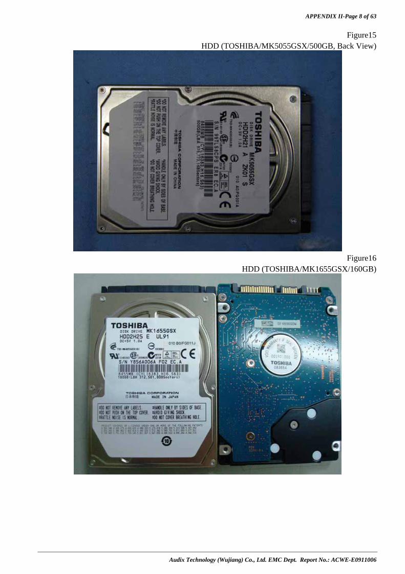
APPENDIX II-Page 8 of 63
Audix Technology (Wujiang) Co., Ltd. EMC Dept. Report No.: ACWE-E0911006
Figure15 HDD (TOSHIBA/MK5055GSX/500GB, Back View)
Figure16
HDD (TOSHIBA/MK1655GSX/160GB)
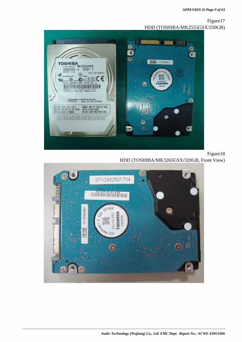
APPENDIX II-Page 9 of 63
Audix Technology (Wujiang) Co., Ltd. EMC Dept. Report No.: ACWE-E0911006
Figure17 HDD (TOSHIBA/MK2555GSX/250GB)
Figure18
HDD (TOSHIBA/MK3265GSX/320GB, Front View)

APPENDIX II-Page 10 of 63
Audix Technology (Wujiang) Co., Ltd. EMC Dept. Report No.: ACWE-E0911006
Figure19 HDD (TOSHIBA/MK3265GSX/320GB, Back View)
Figure20
HDD (WD/1600BEVT-22ZCT0/160GB)

APPENDIX II-Page 11 of 63
Audix Technology (Wujiang) Co., Ltd. EMC Dept. Report No.: ACWE-E0911006
Figure21 HDD (WD/1600BEVT-22A23T0/160GB, Front View)
Figure22
HDD (WD/1600BEVT-22A23T0/160GB, Back View)
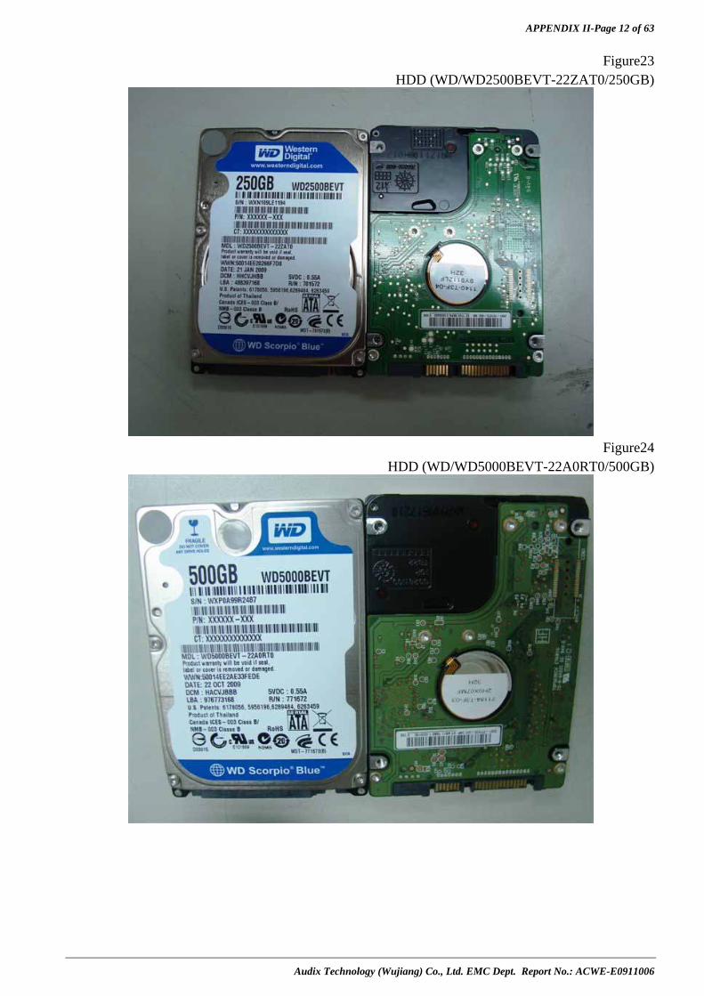
APPENDIX II-Page 12 of 63
Audix Technology (Wujiang) Co., Ltd. EMC Dept. Report No.: ACWE-E0911006
Figure23 HDD (WD/WD2500BEVT-22ZAT0/250GB)
Figure24
HDD (WD/WD5000BEVT-22A0RT0/500GB)
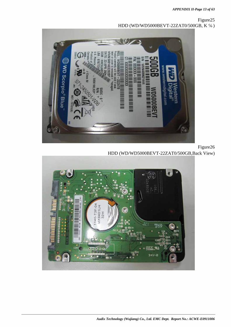
APPENDIX II-Page 13 of 63
Audix Technology (Wujiang) Co., Ltd. EMC Dept. Report No.: ACWE-E0911006
Figure25 HDD (WD/WD5000BEVT-22ZAT0/500GB, 正面)
Figure26
HDD (WD/WD5000BEVT-22ZAT0/500GB,Back View)

APPENDIX II-Page 14 of 63
Audix Technology (Wujiang) Co., Ltd. EMC Dept. Report No.: ACWE-E0911006
Figure27 HDD (WD/WD3200BEVT-22A23T0/320GB, Front View)
Figure28
HDD (WD/WD3200BEVT-22A23T0/320GB, Back View)

APPENDIX II-Page 15 of 63
Audix Technology (Wujiang) Co., Ltd. EMC Dept. Report No.: ACWE-E0911006
Figure29 HDD (WD/WD6400BEVT-22A0RT0/640GB, Front View)
Figure30
HDD (WD/WD6400BEVT-22A0RT0/640GB, Back View)
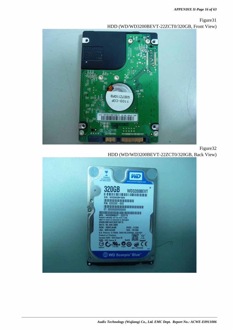
APPENDIX II-Page 16 of 63
Audix Technology (Wujiang) Co., Ltd. EMC Dept. Report No.: ACWE-E0911006
Figure31 HDD (WD/WD3200BEVT-22ZCT0/320GB, Front View)
Figure32
HDD (WD/WD3200BEVT-22ZCT0/320GB, Back View)
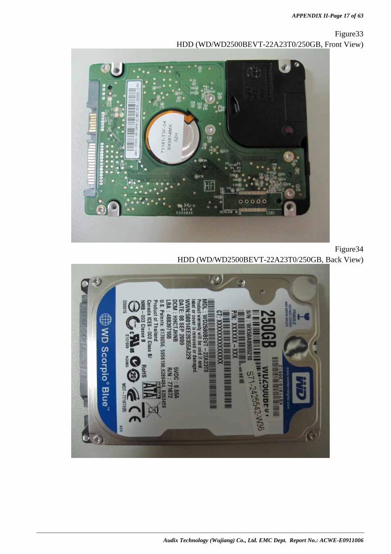
APPENDIX II-Page 17 of 63
Audix Technology (Wujiang) Co., Ltd. EMC Dept. Report No.: ACWE-E0911006
Figure33 HDD (WD/WD2500BEVT-22A23T0/250GB, Front View)
Figure34
HDD (WD/WD2500BEVT-22A23T0/250GB, Back View)
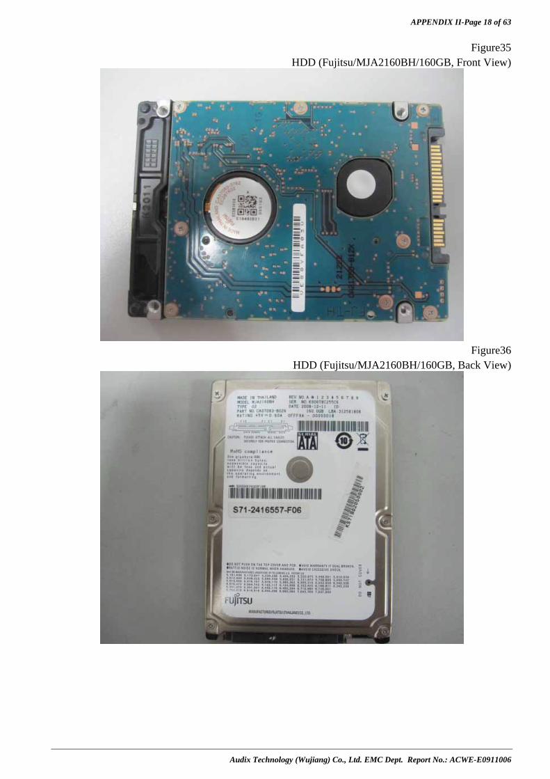
APPENDIX II-Page 18 of 63
Audix Technology (Wujiang) Co., Ltd. EMC Dept. Report No.: ACWE-E0911006
Figure35 HDD (Fujitsu/MJA2160BH/160GB, Front View)
Figure36
HDD (Fujitsu/MJA2160BH/160GB, Back View)
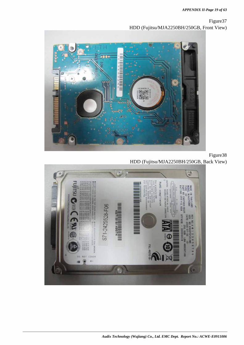
APPENDIX II-Page 19 of 63
Audix Technology (Wujiang) Co., Ltd. EMC Dept. Report No.: ACWE-E0911006
Figure37 HDD (Fujitsu/MJA2250BH/250GB, Front View)
Figure38
HDD (Fujitsu/MJA2250BH/250GB, Back View)

APPENDIX II-Page 20 of 63
Audix Technology (Wujiang) Co., Ltd. EMC Dept. Report No.: ACWE-E0911006
Figure39 HDD (Fujitsu/MJA2320BH/320GB)
Figure40
HDD (Fujitsu/MJA2500BH/500GB,Front View)
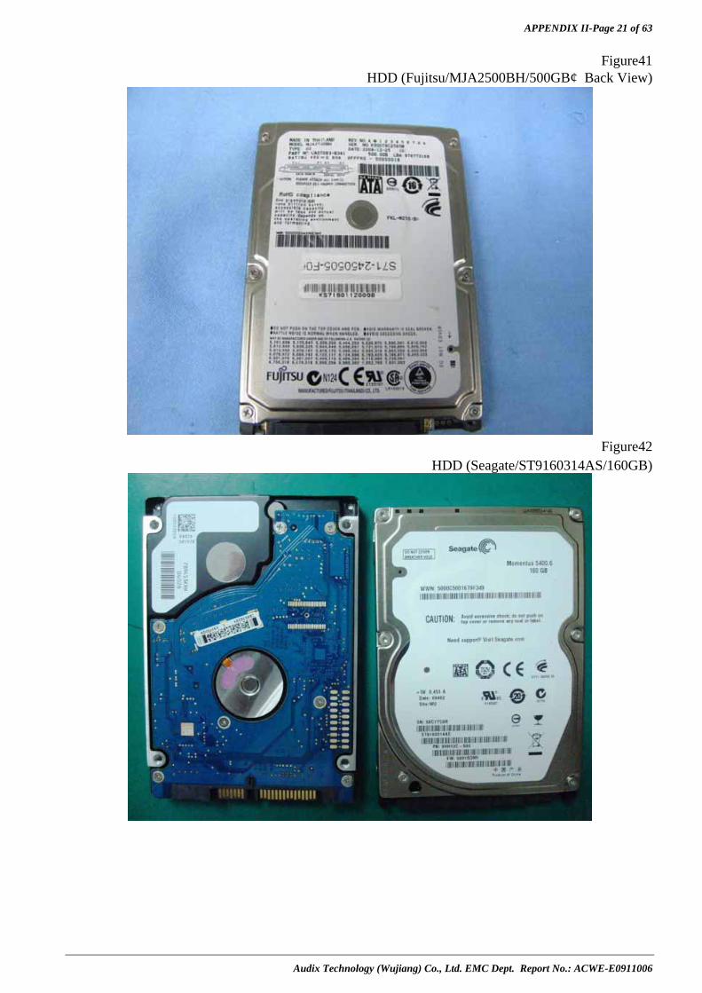
APPENDIX II-Page 21 of 63
Audix Technology (Wujiang) Co., Ltd. EMC Dept. Report No.: ACWE-E0911006
Figure41 HDD (Fujitsu/MJA2500BH/500GB,Back View)
Figure42
HDD (Seagate/ST9160314AS/160GB)
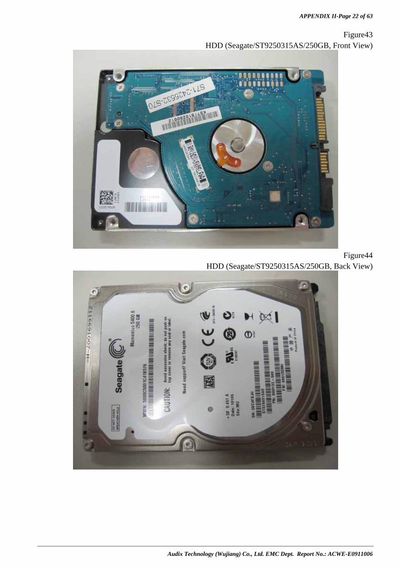
APPENDIX II-Page 22 of 63
Audix Technology (Wujiang) Co., Ltd. EMC Dept. Report No.: ACWE-E0911006
Figure43 HDD (Seagate/ST9250315AS/250GB, Front View)
Figure44
HDD (Seagate/ST9250315AS/250GB, Back View)

APPENDIX II-Page 23 of 63
Audix Technology (Wujiang) Co., Ltd. EMC Dept. Report No.: ACWE-E0911006
Figure45 HDD (Seagate/ST9320325AS/320GB)
Figure46
HDD (Seagate/ST9500325AS/500GB, Front View)
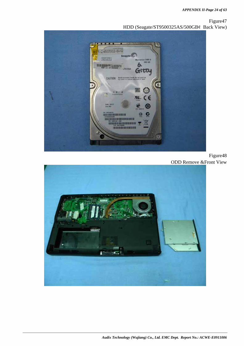
APPENDIX II-Page 24 of 63
Audix Technology (Wujiang) Co., Ltd. EMC Dept. Report No.: ACWE-E0911006
Figure47 HDD (Seagate/ST9500325AS/500GB,Back View)
Figure48
ODD Remove &Front View

APPENDIX II-Page 25 of 63
Audix Technology (Wujiang) Co., Ltd. EMC Dept. Report No.: ACWE-E0911006
Figure49 ODD (HLDS/GT30N, Back View)
Figure50
ODD (Sony/AD-7560S, Front View)
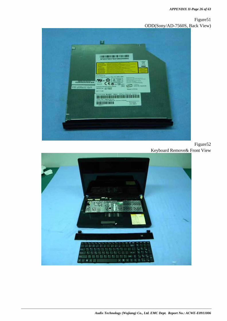
APPENDIX II-Page 26 of 63
Audix Technology (Wujiang) Co., Ltd. EMC Dept. Report No.: ACWE-E0911006
Figure51 ODD(Sony/AD-7560S, Back View)
Figure52
Keyboard Remove& Front View

APPENDIX II-Page 27 of 63
Audix Technology (Wujiang) Co., Ltd. EMC Dept. Report No.: ACWE-E0911006
Figure53 Keyboard(Sunrex/V111922AK1 US, Back View)
Figure54
Internal View (Memory &WLAN remove)

APPENDIX II-Page 28 of 63
Audix Technology (Wujiang) Co., Ltd. EMC Dept. Report No.: ACWE-E0911006
Figure55 Memory (Hynix/HMT125S6BFR8C-G7N0, 2GB/Front View)
Figure56
Memory(Hynix/HMT125S6BFR8C-G7N0, 2GB/Back View)
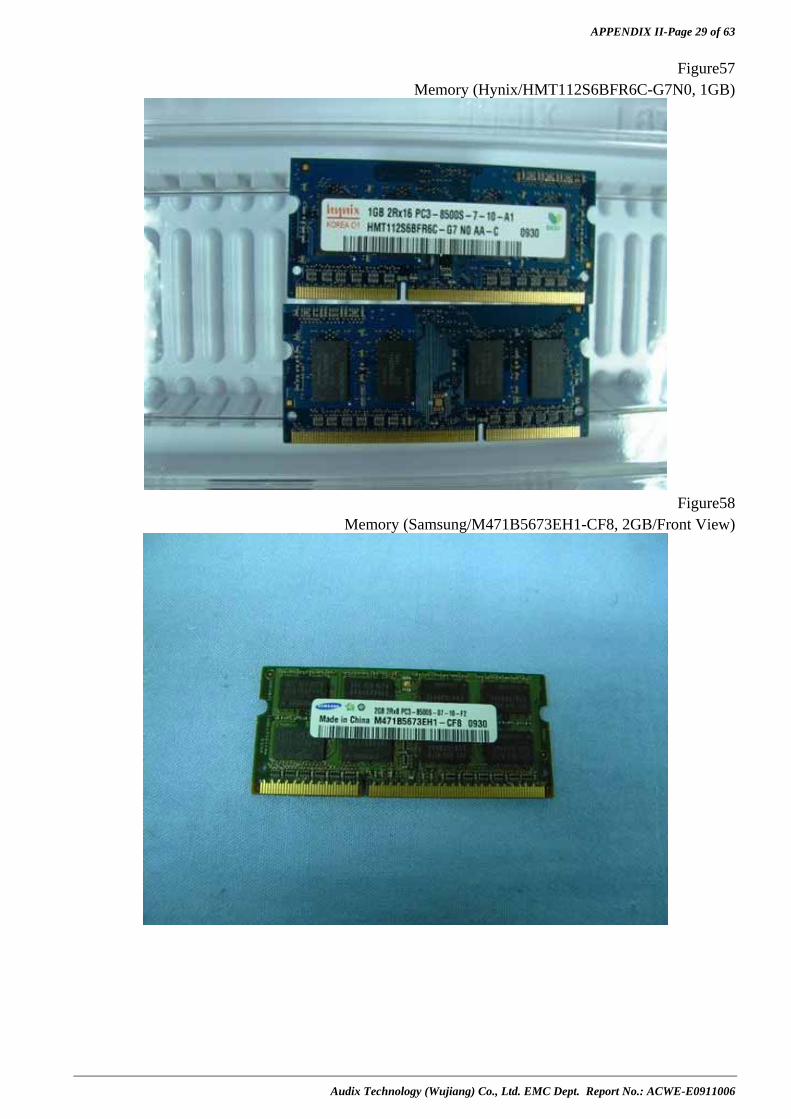
APPENDIX II-Page 29 of 63
Audix Technology (Wujiang) Co., Ltd. EMC Dept. Report No.: ACWE-E0911006
Figure57 Memory (Hynix/HMT112S6BFR6C-G7N0, 1GB)
Figure58
Memory (Samsung/M471B5673EH1-CF8, 2GB/Front View)

APPENDIX II-Page 30 of 63
Audix Technology (Wujiang) Co., Ltd. EMC Dept. Report No.: ACWE-E0911006
Figure59 Memory (Samsung/M471B5673EH1-CF8, 2GB/Back View)
Figure60
WLAN (Atheros/AR5B95/S57-0800290-T46,Front View)
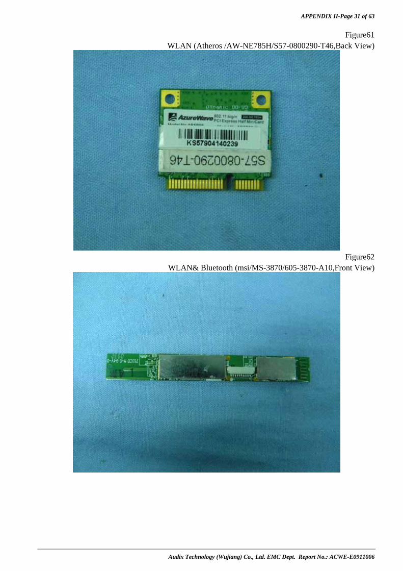
APPENDIX II-Page 31 of 63
Audix Technology (Wujiang) Co., Ltd. EMC Dept. Report No.: ACWE-E0911006
Figure61 WLAN (Atheros /AW-NE785H/S57-0800290-T46,Back View)
Figure62
WLAN& Bluetooth (msi/MS-3870/605-3870-A10,Front View)

APPENDIX II-Page 32 of 63
Audix Technology (Wujiang) Co., Ltd. EMC Dept. Report No.: ACWE-E0911006
Figure63 WLAN& Bluetooth (msi/MS-3870/605-3870-A10,Back View)
Figure64
Bluetooth (CSR/BSMAN1/MS-3801)

APPENDIX II-Page 33 of 63
Audix Technology (Wujiang) Co., Ltd. EMC Dept. Report No.: ACWE-E0911006
Figure65 Frame Remove
Figure66
EMI suppression part

APPENDIX II-Page 34 of 63
Audix Technology (Wujiang) Co., Ltd. EMC Dept. Report No.: ACWE-E0911006
Figure67 EMI suppression part
Figure68
EMI suppression part
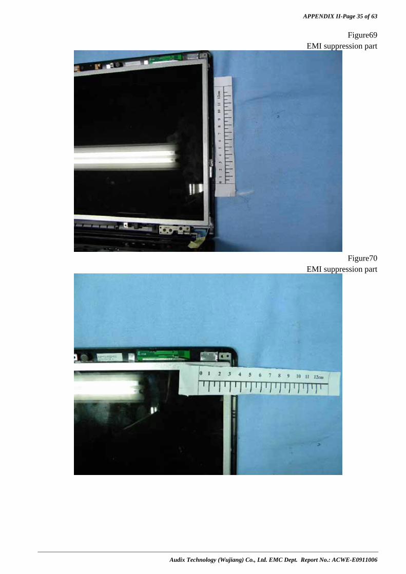
APPENDIX II-Page 35 of 63
Audix Technology (Wujiang) Co., Ltd. EMC Dept. Report No.: ACWE-E0911006
Figure69 EMI suppression part
Figure70
EMI suppression part

APPENDIX II-Page 36 of 63
Audix Technology (Wujiang) Co., Ltd. EMC Dept. Report No.: ACWE-E0911006
Figure71 EMI suppression part
Figure72
LCD Panel Remove
3

APPENDIX II-Page 37 of 63
Audix Technology (Wujiang) Co., Ltd. EMC Dept. Report No.: ACWE-E0911006
Figure73 LCD Panel (AUO/B173RRW01,Front View)
Figure74
LCD Panel (AUO/B173RRW01,Back View)
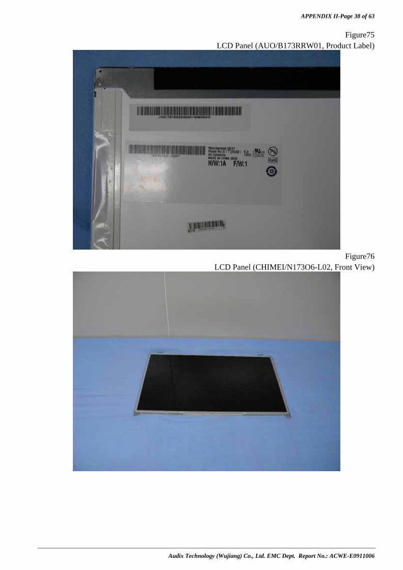
APPENDIX II-Page 38 of 63
Audix Technology (Wujiang) Co., Ltd. EMC Dept. Report No.: ACWE-E0911006
Figure75 LCD Panel (AUO/B173RRW01, Product Label)
Figure76
LCD Panel (CHIMEI/N173O6-L02, Front View)

APPENDIX II-Page 39 of 63
Audix Technology (Wujiang) Co., Ltd. EMC Dept. Report No.: ACWE-E0911006
Figure77 LCD Panel (CHIMEI/N173O6-L02, Back View)
Figure78
LVDS Board(Front View)

APPENDIX II-Page 40 of 63
Audix Technology (Wujiang) Co., Ltd. EMC Dept. Report No.: ACWE-E0911006
Figure79 LVDS Board(Back View)
Figure80
LCD Panel (CHIMEI/N173O6-L02, Product Label)
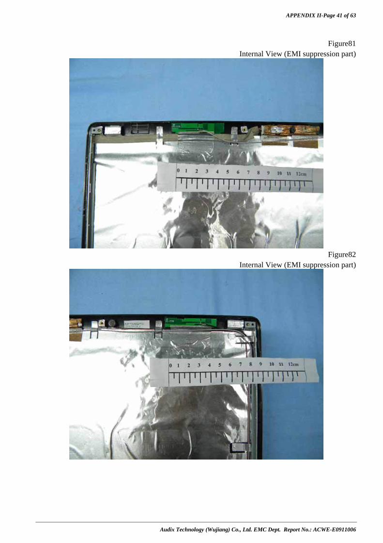
APPENDIX II-Page 41 of 63
Audix Technology (Wujiang) Co., Ltd. EMC Dept. Report No.: ACWE-E0911006
Figure81
Internal View (EMI suppression part)
Figure82
Internal View (EMI suppression part)
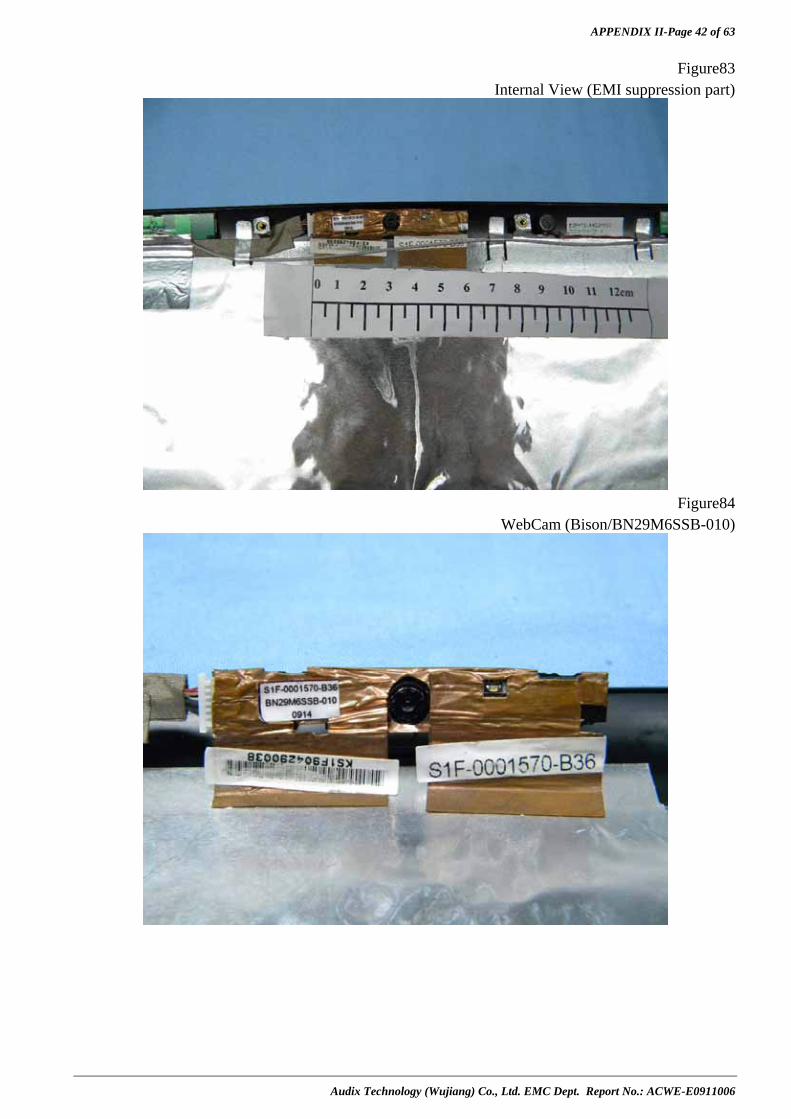
APPENDIX II-Page 42 of 63
Audix Technology (Wujiang) Co., Ltd. EMC Dept. Report No.: ACWE-E0911006
Figure83 Internal View (EMI suppression part)
Figure84
WebCam (Bison/BN29M6SSB-010)

APPENDIX II-Page 43 of 63
Audix Technology (Wujiang) Co., Ltd. EMC Dept. Report No.: ACWE-E0911006
Figure85
WebCam (AZUREWAVE/AM-1C027, Front View)
Figure86
WebCam (AZUREWAVE/AM-1C027, Back View)

APPENDIX II-Page 44 of 63
Audix Technology (Wujiang) Co., Ltd. EMC Dept. Report No.: ACWE-E0911006
Figure87
Antenna Remove
Figure88
Antenna (Front View)

APPENDIX II-Page 45 of 63
Audix Technology (Wujiang) Co., Ltd. EMC Dept. Report No.: ACWE-E0911006
Figure89 Antenna (Back View)
Figure90
Internal View (Heat Sink&Front View)

APPENDIX II-Page 46 of 63
Audix Technology (Wujiang) Co., Ltd. EMC Dept. Report No.: ACWE-E0911006
Figure91 Heat Sink(Back View)
Figure92
Internal View

APPENDIX II-Page 47 of 63
Audix Technology (Wujiang) Co., Ltd. EMC Dept. Report No.: ACWE-E0911006
Figure93 Internal View (EMI suppression part)
Figure94
Touch Pad (SENTELIC/TPA2D2IC99)
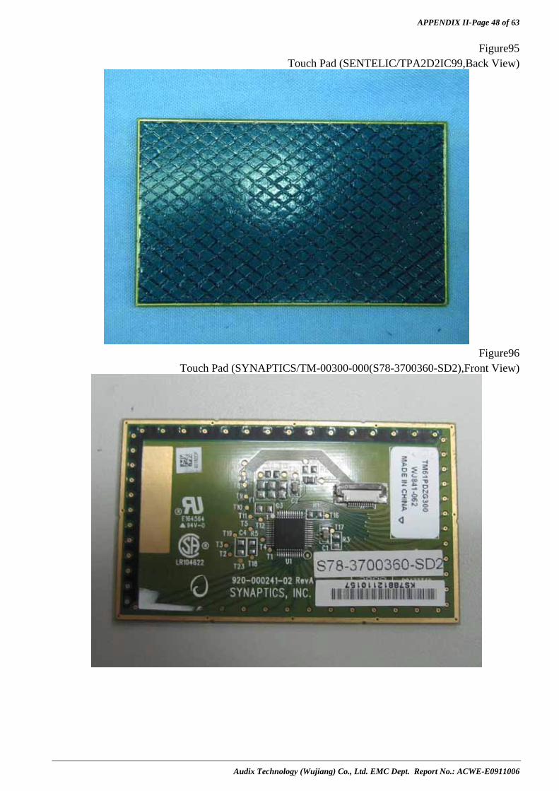
APPENDIX II-Page 48 of 63
Audix Technology (Wujiang) Co., Ltd. EMC Dept. Report No.: ACWE-E0911006
Figure95 Touch Pad (SENTELIC/TPA2D2IC99,Back View)
Figure96
Touch Pad (SYNAPTICS/TM-00300-000(S78-3700360-SD2),Front View)
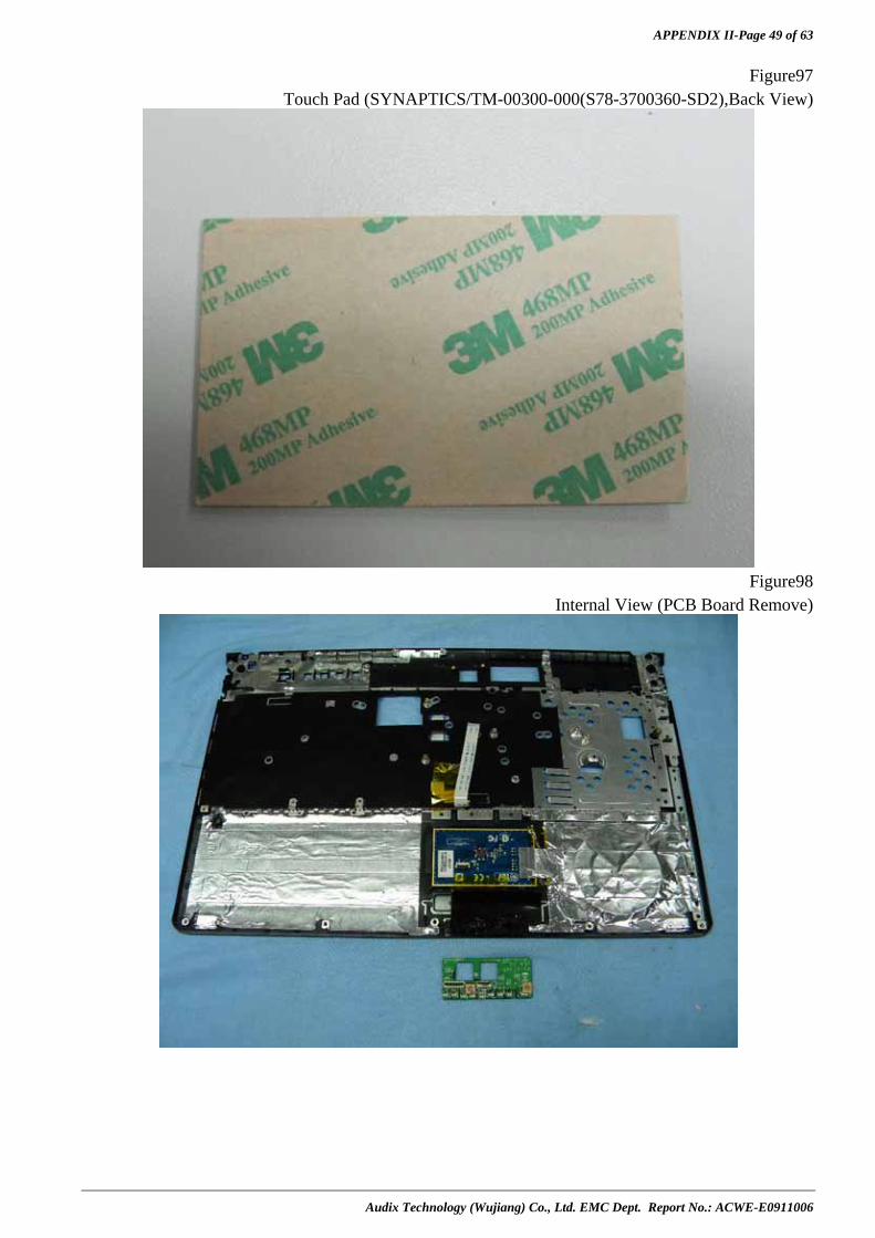
APPENDIX II-Page 49 of 63
Audix Technology (Wujiang) Co., Ltd. EMC Dept. Report No.: ACWE-E0911006
Figure97 Touch Pad (SYNAPTICS/TM-00300-000(S78-3700360-SD2),Back View)
Figure98
Internal View (PCB Board Remove)
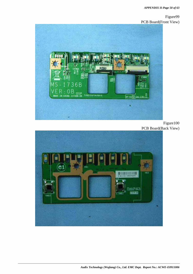
APPENDIX II-Page 50 of 63
Audix Technology (Wujiang) Co., Ltd. EMC Dept. Report No.: ACWE-E0911006
Figure99 PCB Board(Front View)
Figure100
PCB Board(Back View)

APPENDIX II-Page 51 of 63
Audix Technology (Wujiang) Co., Ltd. EMC Dept. Report No.: ACWE-E0911006
Figure101
Main Board Remove
Figure102
Internal View (EMI suppression part)
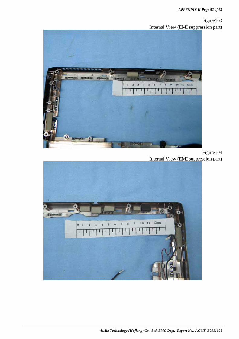
APPENDIX II-Page 52 of 63
Audix Technology (Wujiang) Co., Ltd. EMC Dept. Report No.: ACWE-E0911006
Figure103 Internal View (EMI suppression part)
Figure104
Internal View (EMI suppression part)
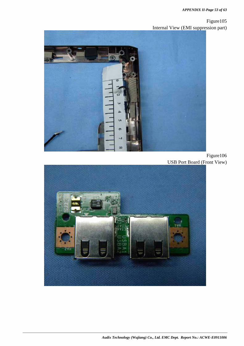
APPENDIX II-Page 53 of 63
Audix Technology (Wujiang) Co., Ltd. EMC Dept. Report No.: ACWE-E0911006
Figure105 Internal View (EMI suppression part)
Figure106
USB Port Board (Front View)

APPENDIX II-Page 54 of 63
Audix Technology (Wujiang) Co., Ltd. EMC Dept. Report No.: ACWE-E0911006
Figure107 USB Port Board (Back View)
Figure108
Main Board (Front View)

APPENDIX II-Page 55 of 63
Audix Technology (Wujiang) Co., Ltd. EMC Dept. Report No.: ACWE-E0911006
Figure109 Main Board (Back View)
Figure110
CPU (INTEL/Q3GB/2.4GHz, Front View)

APPENDIX II-Page 56 of 63
Audix Technology (Wujiang) Co., Ltd. EMC Dept. Report No.: ACWE-E0911006
Figure111 CPU (INTEL/Q3GB/2.4GHz, Back View)
Figure112
CPU (INTEL/Q3G9/2.53GHz, Front View)
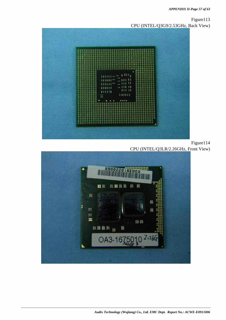
APPENDIX II-Page 57 of 63
Audix Technology (Wujiang) Co., Ltd. EMC Dept. Report No.: ACWE-E0911006
Figure113 CPU (INTEL/Q3G9/2.53GHz, Back View)
Figure114
CPU (INTEL/Q3LR/2.26GHz, Front View)
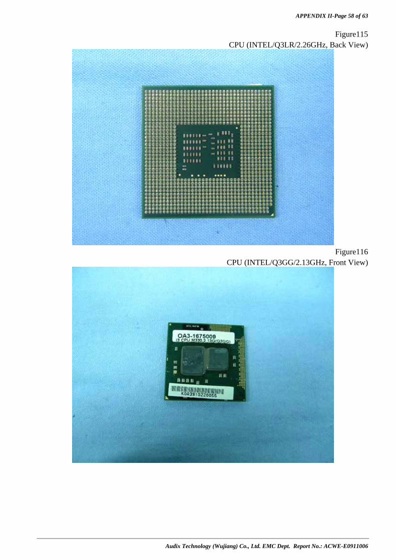
APPENDIX II-Page 58 of 63
Audix Technology (Wujiang) Co., Ltd. EMC Dept. Report No.: ACWE-E0911006
Figure115 CPU (INTEL/Q3LR/2.26GHz, Back View)
Figure116
CPU (INTEL/Q3GG/2.13GHz, Front View)

APPENDIX II-Page 59 of 63
Audix Technology (Wujiang) Co., Ltd. EMC Dept. Report No.: ACWE-E0911006
Figure117
CPU (INTEL/Q3GG/2.13GHz, Back View)
Figure118
Main Board (Crystal Oscillator)

APPENDIX II-Page 60 of 63
Audix Technology (Wujiang) Co., Ltd. EMC Dept. Report No.: ACWE-E0911006
Figure119
Main Board (Crystal Oscillator)
Figure120
Main Board (Crystal Oscillator)

APPENDIX II-Page 61 of 63
Audix Technology (Wujiang) Co., Ltd. EMC Dept. Report No.: ACWE-E0911006
Figure121
Main Board (Crystal Oscillator)
Figure122
AC Adapter (LITEON /PA-1650-68, General Appearance)

APPENDIX II-Page 62 of 63
Audix Technology (Wujiang) Co., Ltd. EMC Dept. Report No.: ACWE-E0911006
Figure123
AC Adapter (LITEON /PA-1650-68, Label)
Figure124
AC Adapter (DELTA /ADP-65HB BB, General Appearance)
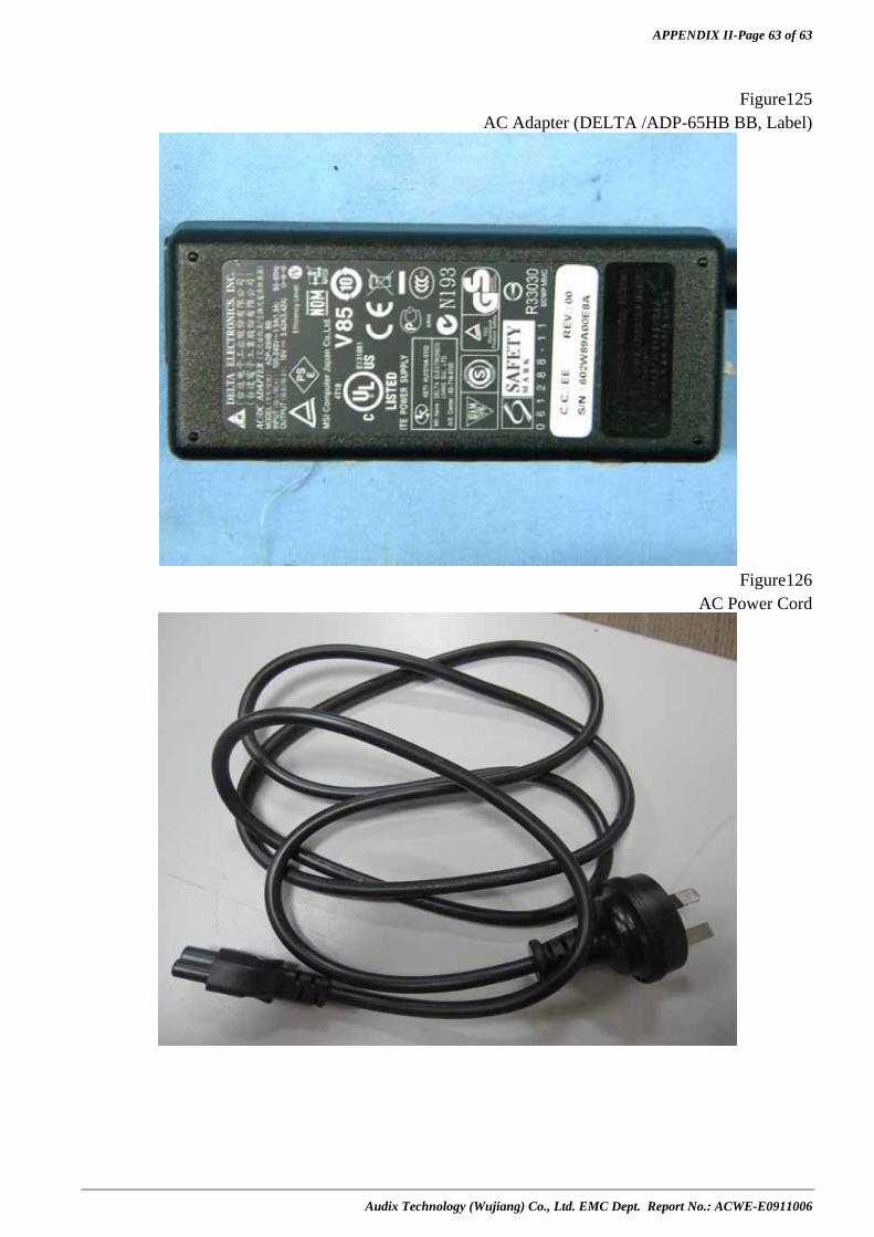
APPENDIX II-Page 63 of 63
Audix Technology (Wujiang) Co., Ltd. EMC Dept. Report No.: ACWE-E0911006
Figure125
AC Adapter (DELTA /ADP-65HB BB, Label)
Figure126
AC Power Cord