emc test report - hardy process solutions 6000 series ce...october 11, 2013 hardy process solutions...
TRANSCRIPT

Nemko USA, Inc. 2210 Faraday Ave, Suite 150 Carlsbad, CA 92008 Phone (760) 444-3500 Fax (760) 444-3005
EMC TEST REPORT
For The Weight Processor
Model: HI6510-WP-10-EIP
Prepared for:
Hardy Process Solutions 9440 Carroll Park Drive Suite 150
San Diego CA 92121
Testing performed per the following:
EMC Directive
2004/108/EC
PREPARED on October 11, 2013
REPORT NUMBER: 2013 10244838 EMC
PROJECT NUMBER: Q10250480
NEX NUMBER: 244838

Nemko USA, Inc. 2210 Faraday Ave, Suite 150 Carlsbad, CA 92008 Phone (760) 444-3500 Fax (760) 444-3005
DATE DOCUMENT NAME DOCUMENT # PAGE
October 11, 2013 Hardy Process Solutions - HI6510-WP-10-EIP - EMC Test Report 2013 10244838 EMC 2 of 49
TABLE OF CONTENTS
DOCUMENT HISTORY .......................................................................................................................................... 4
TEST FACILITY ACCREDITATION ................................................................................................................... 4
CERTIFICATION ..................................................................................................................................................... 5
1. ADMINISTRATIVE DATA AND TEST SUMMARY ................................................................................. 6 1.1.ADMINISTRATIVE DATA ......................................................................................................................................... 6 1.2.REFERENCED STANDARDS FOR RADIATED EMISSIONS ........................................................................................... 7 1.3.REFERENCED STANDARDS FOR ELECTROMAGNETIC COMPATIBILITY .................................................................... 7 1.4.TEST SUMMARY ..................................................................................................................................................... 8
2. SYSTEM CONFIGURATION ...................................................................................................................... 10 2.1.SYSTEM COMPONENTS AND POWER CABLES ........................................................................................................ 10 2.2.DEVICE INTERCONNECTION AND I/O CABLES ...................................................................................................... 10 2.3.DESCRIPTION AND METHOD OF EXERCISING THE EUT ......................................................................................... 10 2.4.DESIGN MODIFICATIONS FOR COMPLIANCE ......................................................................................................... 11
3. MODELS REPRESENTED........................................................................................................................... 12
4. DESCRIPTION OF TEST SITE ................................................................................................................... 15 4.1.DESCRIPTION OF TEST SITE .................................................................................................................................. 15 4.2.TEST SITE REGISTRATIONS ................................................................................................................................... 15
5. DESCRIPTION OF TESTING METHODS ................................................................................................ 16 5.1.INTRODUCTION ..................................................................................................................................................... 16 5.2.TEST METHODS .................................................................................................................................................... 16 5.3.CONFIGURATION AND METHODS OF MEASUREMENTS FOR CONDUCTED EMISSIONS ............................................ 16 5.4.CONFIGURATION AND METHODS OF MEASUREMENTS FOR RADIATED EMISSIONS ............................................... 17 5.5.POWER LINE HARMONICS: EN 61000-3-2: 2006+A1:2009+A2:2009 .................................................................. 18 5.6.POWER LINE FLUCTUATIONS/FLICKER: EN 61000-3-3: 2008 ............................................................................... 18 5.7.DEVICE PERFORMANCE CRITERIA FOR IMMUNITY TESTS ..................................................................................... 19 5.8.ELECTROSTATIC DISCHARGE IMMUNITY: EN 61000-4-2: 2009 ............................................................................ 20 5.9.RADIO FREQUENCY IMMUNITY: EN 61000-4-3: 2006 +A1:2008 +A2:2010 ........................................................ 20 5.10.ELECTRICAL FAST TRANSIENT IMMUNITY: EN 61000-4-4: 2004+A1: 2010 ...................................................... 21 5.11.POWER LINE SURGE IMMUNITY: EN 61000-4-5: 2006 ....................................................................................... 21 5.12.RADIO FREQUENCY CONDUCTED COMMON MODE IMMUNITY: EN 61000-4-6: 2009 ........................................ 21 5.13.POWER FREQUENCY MAGNETIC FIELD IMMUNITY: EN 61000-4-8: 2010 ........................................................... 22 5.14.VOLTAGE DIPS AND SHORT INTERRUPTIONS: EN 61000-4-11: 2004 .................................................................. 22 5.15.TELECOM CONDUCTED EMISSIONS TEST DATA .................................................................................................. 23 5.16.RADIATED EMISSIONS TEST DATA ..................................................................................................................... 24 5.18.ELECTROSTATIC DISCHARGE IMMUNITY TEST RESULTS & TEST POINTS ........................................................... 27 5.19.RADIO FREQUENCY IMMUNITY TEST RESULTS ................................................................................................... 34 5.20.ELECTRICAL FAST TRANSIENT BURST IMMUNITY TEST RESULTS ...................................................................... 36 5.21.RF CONDUCTED COMMON MODE DISTURBANCE IMMUNITY TEST RESULTS ..................................................... 37 5.22.POWER FREQUENCY MAGNETIC FIELD IMMUNITY ............................................................................................. 38
TEST SETUP DIAGRAMS Figure 1.ESD Test Points .......................................................................................................................................... 28

Nemko USA, Inc. 2210 Faraday Ave, Suite 150 Carlsbad, CA 92008 Phone (760) 444-3500 Fax (760) 444-3005
DATE DOCUMENT NAME DOCUMENT # PAGE
October 11, 2013 Hardy Process Solutions - HI6510-WP-10-EIP - EMC Test Report 2013 10244838 EMC 3 of 49
Figure 2.ESD Test Points .......................................................................................................................................... 29 Figure 3.ESD Test Points .......................................................................................................................................... 30 Figure 4.ESD Test Points .......................................................................................................................................... 31 Figure 5.ESD Test Points .......................................................................................................................................... 32 Figure 6.ESD Test Points .......................................................................................................................................... 33
TEST CONFIGURATION PHOTOGRAPHS Photograph 1. Photo of Radiated Emissions Modification ........................................................................................ 11 Photograph 2.EUT Front and Rear ............................................................................................................................ 13 Photograph 3. General EUT Test Configuration ....................................................................................................... 14 Photograph 4. Conducted Emissions Test Configuration .......................................................................................... 39 Photograph 5. Radiated Emissions Test Configuration ............................................................................................. 40 Photograph 6. ESD Test Configuration ..................................................................................................................... 41 Photograph 7. Radio Frequency Immunity Test Configuration ................................................................................. 42 Photograph 8. EFT Immunity Test Configuration ..................................................................................................... 43 Photograph 9. RF Conducted Immunity Test Configuration ..................................................................................... 44 Photograph 10. Power Frequency Magnetic Field Immunity Test Configuration ..................................................... 45
APPENDICES A. RADIATED EMISSIONS MEASUREMENT UNCERTAINTIES ....................................................................................... 46 B. NEMKO USA, INC. TEST EQUIPMENT & FACILITIES CALIBRATION PROGRAM ....................................................... 48

Nemko USA, Inc. 2210 Faraday Ave, Suite 150 Carlsbad, CA 92008 Phone (760) 444-3500 Fax (760) 444-3005
DATE DOCUMENT NAME DOCUMENT # PAGE
October 11, 2013 Hardy Process Solutions - HI6510-WP-10-EIP - EMC Test Report 2013 10244838 EMC 4 of 49
DOCUMENT HISTORY
REVISION DATE COMMENTS
- October 11, 2013 Prepared By: William Dey
- October 11, 2013 Initial Release: Alan Laudani
NOTE: Nemko USA, Inc. hereby makes the following statements so as to conform to the Subclause 5.10 Requirements of ISO/IEC 17025 "General Criteria For the Competence Of Testing and Calibration Laboratories":
o The unit described in this report was received at Nemko USA, Inc.'s facilities on October 1, 2013.
o Testing was performed on the unit described in this report on October 1, 2013 to October 7, 2013.
o The Test Results reported herein apply only to the Unit actually tested, and to substantially identical Units.
o This report does not imply the endorsement of the Federal Communications Commission (FCC), NVLAP or any other government agency.
This Report is the property of Nemko USA, Inc., and shall not be reproduced, except in full, without prior written approval of Nemko USA, Inc. However, all ownership rights are hereby returned unconditionally to Hardy Process Solutions and approval is hereby granted to Hardy Process Solutions and its employees and agents to reproduce all or part of this report for any legitimate business purpose without further reference to Nemko USA, Inc.
Test Facility Accreditation Nemko USA, Inc. is accredited through National Voluntary Laboratory Accreditation Program.
NVLAP LAB CODE 200116-0
This report must not be used by the client to claim product certification, approval,
or endorsement by NVLAP, NIST, or any agency of the Federal Government.

Nemko USA, Inc. 2210 Faraday Ave, Suite 150 Carlsbad, CA 92008 Phone (760) 444-3500 Fax (760) 444-3005
DATE DOCUMENT NAME DOCUMENT # PAGE
October 11, 2013 Hardy Process Solutions - HI6510-WP-10-EIP - EMC Test Report 2013 10244838 EMC 5 of 49
CERTIFICATION
The compatibility testing and this report have been prepared by Nemko USA, Inc., an independent electromagnetic
compatibility consulting and test laboratory.
Testing and data collection were accomplished in accordance with the test methods listed in this report.
I certify the data evaluation and equipment configuration herein to be a true and accurate representation of the
sample's test characteristics, as of the test date(s), and for the design of the test sample utilized to compile this
report.
Bruce Ketterling EMC Division Manager, Nemko USA, Inc.

Nemko USA, Inc. 2210 Faraday Ave, Suite 150 Carlsbad, CA 92008 Phone (760) 444-3500 Fax (760) 444-3005
DATE DOCUMENT NAME DOCUMENT # PAGE
October 11, 2013 Hardy Process Solutions - HI6510-WP-10-EIP - EMC Test Report 2013 10244838 EMC 6 of 49
1. ADMINISTRATIVE DATA AND TEST SUMMARY
1.1. Administrative Data
CLIENT: Hardy Process Solutions 9440 Carroll Park Drive Suite 150 San Diego CA 92121 (858) 278-2900 EXT. 1407
CONTACT: Lito Guiriba E-Mail: [email protected]
DATE (S) OF TEST: October 1, 2013 to October 7, 2013.
EQUIPMENT UNDER TEST (EUT): Weight Processor MODEL TESTED: HI6510-WP-10-EIP MODELS REPRESENTED: REFER TO SECTION 3 SERIAL NUMBER: 4 SOFTWARE REVISION: HI6500 1.0.0.16 CONDITION UPON RECEIPT: Suitable for Test
TEST SPECIFICATION: Radio Frequency Emissions and Electromagnetic Immunity tests in
accordance with requirements of standard EN 61326-1: 2013.
Emissions Class: “A” Electromagnetic Environment:
Basic EM Environment Industrial EM Environment Industrial EM Environment

Nemko USA, Inc. 2210 Faraday Ave, Suite 150 Carlsbad, CA 92008 Phone (760) 444-3500 Fax (760) 444-3005
DATE DOCUMENT NAME DOCUMENT # PAGE
October 11, 2013 Hardy Process Solutions - HI6510-WP-10-EIP - EMC Test Report 2013 10244838 EMC 7 of 49
1.2. Referenced Standards for Radiated Emissions
Test Type In Accordance with Document
Document Title
Conducted and Radiated Emissions
EN 55011:2009+A1:2010 Information technology equipment—Radio disturbance characteristics —Limits and methods of measurement
Power Line Harmonics EN 61000-3-2: 2006+A1:2009+A2:2009
Electromagnetic Compatibility, Limits for Harmonic Current Emissions, Equipment Input Current < 16A
Power Line Flicker EN 61000-3-3: 2008 Electromagnetic Compatibility, Limitation of Voltage Fluctuations and Flicker In Low-Voltage Supply Systems for Equipment with Rated Current < 16A
1.3. Referenced Standards for Electromagnetic Compatibility
Test Type In Accordance with
Document Document Title
Electrostatic Discharge Immunity
EN 61000-4-2:2009 Electromagnetic Compatibility—Testing and measurement techniques - Electrostatic discharge immunity test
Radio Frequency Immunity
EN 61000-4-3:2006 + A1:2008 + A2:2010
Electromagnetic Compatibility—Testing and measurement techniques - Radiated radio frequency electromagnetic field immunity test
Electrical Fast Transient Burst Immunity
EN 61000-4-4: 2004+A1: 2010
Electromagnetic Compatibility—Testing and measurement techniques - Electrical fast transient / burst immunity
Power Line Surge Immunity
EN 61000-4-5: 2006 Electromagnetic Compatibility—Testing and measurement techniques - Surge immunity test
RF Common Mode Immunity
EN 61000-4-6: 2009 Electromagnetic Compatibility—Testing and measurement techniques - Immunity to conducted disturbances, induced by radio-frequency fields
Power Frequency Magnetic Field
EN 61000-4-8: 2010 Electromagnetic Compatibility—Testing and measurement techniques - for Power Frequency Magnetic Field, Immunity Test
Voltage Dips and Short Interruptions Immunity
EN 61000-4-11: 2004 Electromagnetic Compatibility—Testing and measurement techniques - Voltage dips, short interruptions and voltage variations immunity tests

Nemko USA, Inc. 2210 Faraday Ave, Suite 150 Carlsbad, CA 92008 Phone (760) 444-3500 Fax (760) 444-3005
DATE DOCUMENT NAME DOCUMENT # PAGE
October 11, 2013 Hardy Process Solutions - HI6510-WP-10-EIP - EMC Test Report 2013 10244838 EMC 8 of 49
1.4. Test Summary 1.4.1. Emissions Test Summary The Compliance Status is a judgment based on the calculated highest emissions to appropriate standard limits. Measurement uncertainty values, provided on calibration certificates, were not be used in the judgment of the final status of compliance.
Test Methods Frequency Range Compliance Status EN 55011:2009+A1:2010, Class “A”
Conducted Emissions 0.15 MHz – 30 MHz N/A
EN 55022: 2010+AC: 2011, Class “A” Telecom Conducted Emissions 0.15 MHz – 30 MHz PASS
EN 55011:2009+A1:2010, Class “A” Radiated Emissions 30 MHz – 1000 MHz PASS
EN 61000-3-2: 2006+A1:2009+A2:2009 Power Line Harmonics up to the 40th Harmonic N/A
EN 61000-3-3: 2008 Power Line Flicker
less than or equal to 4% Maximum Relative Voltage Change; Value of D(T) less than or
equal to 3% for more than 200 ms N/A
Senior RF/EMC Engineer Test Report Verificator

Nemko USA, Inc. 2210 Faraday Ave, Suite 150 Carlsbad, CA 92008 Phone (760) 444-3500 Fax (760) 444-3005
DATE DOCUMENT NAME DOCUMENT # PAGE
October 11, 2013 Hardy Process Solutions - HI6510-WP-10-EIP - EMC Test Report 2013 10244838 EMC 9 of 49
1.4.2. Immunity Test Summary
Test Methods Minimum Criterion Level
Required as per EN 61326-1 Criterion Level
Tested Compliance
Status
EN 61000-4-2: 2009 - ESD Immunity
Criterion B ±8 kV air discharge,
±4 kV contact discharge
Criterion A ±8 kV Air Discharge,
±4 kV Contact Discharge PASS
EN 61000-4-3: 2006 +A1:2008 +A2:2010 -
Radio Frequency Immunity
Criterion A10 V/m from 80-1000 MHz 10 V/m from 1.4-2.0 GHz 3 V/m from -2.0-2.7 GHz (80% AM at 1kHz)
Criterion A10 V/m from 80-1000 MHz 10 V/m from 1.4-2.0 GHz 3 V/m from 2.0-2.7 GHz (80% AM at 1kHz)
PASS
EN 61000-4-4: 2004+A1: 2010
-Electrical Fast Transient Immunity
Criterion B Power line pulses of ± 2 kV; I/O line pulses of ± 1.0 kV
Criterion B Power Line Pulses of ± 2 kV; I/O Line Pulses of ± 1.0 kV
PASS
EN 61000-4-5: 2006 -Surge Immunity
Criterion B ±2kV common mode surges, ±1kV
differential mode surges
Criterion B ±2kV Common Mode Surges,
±1kV Differential Mode Surges N/A*
EN 61000-4-6: 2009 -RF Common Mode
Immunity
Criterion A 150 kHz - 80 MHz at 10 Vrms
1 kHz 80% amplitude modulated
Criterion A 150 kHz - 80 MHz at 10 Vrms
1kHz 80% amplitude modulated PASS
EN 61000-4-8: 2010 Power Frequency Magnetic
Field
Criterion A Inductive loop at 50/60 Hz, to 30 amps (rms) per meter
Criterion A Inductive loop at 50/60 Hz, To 30 amps (rms) per meter
PASS
EN 61000-4-11: 2004 - Voltage Dips and Short
Interruptions
Criterion B and C Voltage Dips of 30%, 60% and >95%; Interruptions of >95%.
Criterion B and C Voltage Dips of 30%, 60% and >95%; Interruptions of >95%.
N/A
*Not applicable for DC EUT as EUT will be used with a Class 2 power supply per section 8.2 of IEC 61000-4-5, 2005.Surges to low voltage d.c. input/output ports (≤ 60 V) are not applied in the case, when the secondary circuits (isolated from the a.c. mains) are not subject to transient overvoltages (i.e. reliably-grounded, capacitively-filtered d.c. secondary circuits where the peak-to-peak ripple is less than 10 % of the d.c. component.) Refer to the test results section for further details.
Senior RF/EMC Engineer Test Report Verificator

Nemko USA, Inc. 2210 Faraday Ave, Suite 150 Carlsbad, CA 92008 Phone (760) 444-3500 Fax (760) 444-3005
DATE DOCUMENT NAME DOCUMENT # PAGE
October 11, 2013 Hardy Process Solutions - HI6510-WP-10-EIP - EMC Test Report 2013 10244838 EMC 10 of 49
2. SYSTEM CONFIGURATION
2.1. System Components and Power Cables DEVICE
MANUFACTURER MODEL # SERIAL #
POWER CABLE
EUT – Weight Processor Hardy Process Solutions Model: HI6510-WP-10-EIP Serial #: 4
2m, unshielded, 18 AWG, 2-wire, DC positive and negative wires, ground braid
Support – Bench Scale Hardy Process Solutions Model: 1212SBU Serial #: 2627
N/A
Support – Laptop Computer Dell Model: PP05L Serial #: N/A
2m, unshielded, 18 AWG, 2-wire, 1EC connector
2.2. Device Interconnection and I/O Cables
Connection I/O Cable
EUT to Bench Scale Load Cell Cable, shielded, 20ft
EUT to Laptop computer RJ45 Cable, unshielded, 3ft
EUT to Laptop computer RS485 Cable, shielded, 20ft, to USB Cable, shielded, 3ft
2.3. Description and Method of Exercising the EUT The HI6510-WP-10-EIP is a Weight Processor. Its function is to be used as a stand-alone weight processor or for front-end to weight-based control systems. The instruments read, condition, and digitize load cell and strain gage signals commonly found in industrial process weighing applications, including inventory management, batching, blending, filling, dispensing, and check weighing. The EUT was exercised by a continuously running program. If the program is disrupted, or there is loss of functionality, this may be considered a failure. The EUT was monitored by a laptop running HI6500 1.0.0.16 software where weight readings are displayed in real time. The fail mode for the EUT is when it loses communication with the laptop or there is weight change of +/- 1.5 grams or more. The HI6510-WP-10-EIP has HI6500 1.0.0.16 program used during the EMI evaluation. The EUT’s performance during test was evaluated against the performance criterion specified by applicable test standards. Performance results are detailed in the test results section of this report.

Nemko USA, Inc. 2210 Faraday Ave, Suite 150 Carlsbad, CA 92008 Phone (760) 444-3500 Fax (760) 444-3005
DATE DOCUMENT NAME DOCUMENT # PAGE
October 11, 2013 Hardy Process Solutions - HI6510-WP-10-EIP - EMC Test Report 2013 10244838 EMC 11 of 49
2.4. Design Modifications for Compliance
Device: Weight Processor Model: HI6510-WP-10-EIP The following design modifications were made to the EUT during testing. For Radiated Emissions: Added 1 Ferrite, Manufacturer: Wurth Elektronik, Serial Number: 742 711 42, internally to display cable.
Photograph 1. Photo of Radiated Emissions Modification

Nemko USA, Inc. 2210 Faraday Ave, Suite 150 Carlsbad, CA 92008 Phone (760) 444-3500 Fax (760) 444-3005
DATE DOCUMENT NAME DOCUMENT # PAGE
October 11, 2013 Hardy Process Solutions - HI6510-WP-10-EIP - EMC Test Report 2013 10244838 EMC 12 of 49
3. Models Represented The HI6300/HI6500 Series of Weight Processor consist of the following models, which according to Manufacturer, are all based on the same design and configuration: Per manufacturer, models HI6510-WP-10-EIP and HI6500-WP-10-PB were selected as worst case representative of all models. Standard Hardware Configuration: HI6300 Ethernet Port, Modbus-RTU, RS232/RS485 HI6310 Ethernet Port, Modbus-RTU, RS232/RS485, USB Port, Analog Output (4-20mA) HI6500 Ethernet Port, Modbus-RTU, RS232/RS485, USB Port HI6510 Ethernet Port, Modbus-RTU, RS232/RS485, USB Port, Analog Output (4-20mA) Product Nomenclature: Series Models Application Software Display Options Network Options HI6300 -WP (Weight Processor) -00 (No Display)
-10 (With Display) -00 (No Network)
Series Models Application Software Display Options Network Options HI6310 -WP (Weight Processor) -00 (No Display)
-10 (With Display) -00 (No Network)
Series Models Application Software Display Options Network Options HI6500 -WP (Weight Processor) -00 (No Display)
-10 (With Display) -20 (With Color Display)
-00 (No Network) -EIP (Ethernet IP) -PB (Profibus-DP)
Series Models Application Software Display Options Network Options HI6510 -WP (Weight Processor) -00 (No Display)
-10 (With Display) -20 (With Color Display)
-00 (No Network) -EIP (Ethernet IP) -PB (Profibus-DP)

Nemko USA, Inc. 2210 Faraday Ave, Suite 150 Carlsbad, CA 92008 Phone (760) 444-3500 Fax (760) 444-3005
DATE DOCUMENT NAME DOCUMENT # PAGE
October 11, 2013 Hardy Process Solutions - HI6510-WP-10-EIP - EMC Test Report 2013 10244838 EMC 13 of 49
Photograph 2.EUT Front and Rear
EUT Front
EUT Rear

Nemko USA, Inc. 2210 Faraday Ave, Suite 150 Carlsbad, CA 92008 Phone (760) 444-3500 Fax (760) 444-3005
DATE DOCUMENT NAME DOCUMENT # PAGE
October 11, 2013 Hardy Process Solutions - HI6510-WP-10-EIP - EMC Test Report 2013 10244838 EMC 14 of 49
Photograph 3. General EUT Test Configuration

Nemko USA, Inc. 2210 Faraday Ave, Suite 150 Carlsbad, CA 92008 Phone (760) 444-3500 Fax (760) 444-3005
DATE DOCUMENT NAME DOCUMENT # PAGE
October 11, 2013 Hardy Process Solutions - HI6510-WP-10-EIP - EMC Test Report 2013 10244838 EMC 15 of 49
4.DESCRIPTION OF TEST SITE
4.1. Description of Test Site The test site is located at 2210 Faraday Ave., Suite 150, Carlsbad, CA 92008. Radiated emissions measurements are performed in the 10 meter Semi-Anechoic chamber, which conforms to the volumetric normalized site attenuation (VNSA) for three and ten-meter measurements. The chamber also conforms to the SVSWR compliance requirements for 1-18 GHz measurements. The VNSA and SVSWR meet the technical requirements, as set, in the CISPR 16 and ANSI C63.4 documents. Facility test areas for conducted emissions and immunity testing also meet the construction and characteristics, as required by CISPR 16 and ANSI C63.4 documents. Emissions measurements are performed using TILE software. Version 4.0.A.7 for radiated and version 3.4.K.24 for conducted.
4.2. Test Site Registrations
Organization Registration and Recognition numbers
Federal Communications Commission 0013750831 / US5058 Industry Canada 2040B-3
VCCI R-3856 / G-549 (Radiated emissions) and C-4320 / T-1315(Conducted emissions)
Korean Ministry (APEC Tel MRA) US0088

Nemko USA, Inc. 2210 Faraday Ave, Suite 150 Carlsbad, CA 92008 Phone (760) 444-3500 Fax (760) 444-3005
DATE DOCUMENT NAME DOCUMENT # PAGE
October 11, 2013 Hardy Process Solutions - HI6510-WP-10-EIP - EMC Test Report 2013 10244838 EMC 16 of 49
5.DESCRIPTION OF TESTING METHODS
5.1. Introduction Nemko USA, Inc. is accredited to ISO/IEC 17025 by the National Voluntary Laboratory Accreditation Program (NVLAP) for Electromagnetic Compatibility and Telecommunications testing. Part of the accreditation process involves the demonstration of competence in various test methods. Prior to the beginning of work, Nemko personnel work with their clients to ensure the proper test standards and test methods are utilized. Applicable tests and the minimum criteria for a pass condition are listed in the administrative section of this report.
5.2. Test Methods The harmonized documents published for Information Technology Equipment are EN 55022: 2010+AC: 2011 for radio frequency emissions and EN 55024: 2010 for electromagnetic immunity. The methods employed to test the emissions and immunity characteristics of the Equipment Under Test are those mandated by the European Standards EN 55022 and EN 55024.The applicable tests and the minimum criteria for a pass condition that are listed in the administrative section of this report are taken from these standards. Digital devices sold in Canada are required to comply with the Interference Causing Equipment Standard for Digital Apparatus, ICES-003, Issue 5, Dated August 2012.These test methods and limits are specified in the Canadian Standards Association’s Standard CAN/CSA-CISPR 22-10 and are “essentially equivalent” with the CISPR 22 (EN55022) rules for unintentional radiators.
5.3. Configuration and Methods of Measurements for Conducted Emissions
This test measures the levels emanating from the EUT, thus evaluating the potential for the EUT to cause radio frequency interference to other electronic devices. Testing was performed in accordance with the test standard(s) referenced in the test summary section of this report. The Equipment Under Test (EUT) was configured based upon the requirements of the applicable test standard.

Nemko USA, Inc. 2210 Faraday Ave, Suite 150 Carlsbad, CA 92008 Phone (760) 444-3500 Fax (760) 444-3005
DATE DOCUMENT NAME DOCUMENT # PAGE
October 11, 2013 Hardy Process Solutions - HI6510-WP-10-EIP - EMC Test Report 2013 10244838 EMC 17 of 49
5.4. Configuration and Methods of Measurements for Radiated Emissions
This test measures the levels emanating from the EUT, thus evaluating the potential for the EUT to cause radio frequency interference to other electronic devices. Testing was performed in accordance with the test standard(s) referenced in the test summary section of this report. The Equipment Under Test (EUT) was configured based upon the requirements of the applicable test standard. Initial prescans for radiated emissions were performed as suggested per ANSI 63.22. The antenna is positioned at several heights while the EUT is rotated 360°. At each antenna height, the receiver scans and records the maximum emissions in the required frequency range as required by the applicable standards. From the recorded scans, a list of discrete frequencies is developed. To ensure that the maximum emission at each discrete frequency of interest is observed, the receive antenna is varied in height from one to four meters and rotated to produce horizontal and vertical polarities while the turntable is rotated to determine the worst emitting configuration. The numerical results are included herein to demonstrate compliance. The numerical results of the test are included herein to demonstrate compliance.
The numerical results that are applied to the emissions limits are arrived as demonstrated by the example below: The numerical results that are applied to the emissions limits are arrived as demonstrated by the example below:
A B C D E F G H I Measurement
Frequency (MHz)
Meter Reading (dBμV)
Turn Table
(degrees)
Antenna Height (cm)
Corrected Reading (dBμV/m)
Limit
(dBμV/m)
Margin
(dB)
Pass Fail
Comments
A. Frequency Measured in MHz B. Meter Reading: Emission Amplitude as measured with the antenna in dBμV, this is from the EMI receiver or Spectrum Analyzer. C. Turn Table reading in degrees. D. Antenna Height in centimeters. E. Corrected Reading, the meter reading with the antenna factor, cable loss, attenuator loss, and preamplifier gain added in. This is the emission value to compare to the limit. F. Limit from the specification. G. Margin: difference in dB of Corrected Reading and Specification Limit, negative results indicate a margin value below the specification limit. H. Pass Fail: Result; EUT does or does not comply at this frequency. I. Comments. If any, the technician enters remarks special to the test performed.

Nemko USA, Inc. 2210 Faraday Ave, Suite 150 Carlsbad, CA 92008 Phone (760) 444-3500 Fax (760) 444-3005
DATE DOCUMENT NAME DOCUMENT # PAGE
October 11, 2013 Hardy Process Solutions - HI6510-WP-10-EIP - EMC Test Report 2013 10244838 EMC 18 of 49
5.5. Power Line Harmonics: EN 61000-3-2: 2006+A1:2009+A2:2009
This test evaluates the potential for the EUT to cause distortion on the AC power lines. Testing was performed in
accordance with EN 61000-3-2.It is applicable to electrical and electronic equipment having an input current up to
and including 16 amps per phase, and intended to be connected to public low-voltage distribution systems.
Basic requirements of the AC source include a ± 2% voltage regulation and a ± 0.5% frequency limit. A low
distortion sine wave output is required to ensure that the AC source does not adversely contribute distortion to the
load, meeting the following limits:
o 0.9% for 3rd order harmonics
o 0.4% for 5th order harmonics
o 0.3% for 7th order harmonics
o 0.2% for 9th order harmonics
o 0.2% for even harmonics of order 2 to 10
o 0.1% for odd harmonic order from 11 to 40
For further information, please refer to the technical sections in the EN 61000-3 in addition to the test results section
and photographs of the test set-up provided in this report.
5.6. Power Line Fluctuations/Flicker: EN 61000-3-3: 2008
Testing was performed in accordance with EN 61000-3-3.It is applicable to household appliances and similar
electrical and electronic equipment having an input current up to and including 16 amps per phase. The objective of
this standard is to set limits for voltage fluctuations of equipment within its scope, and ensures that home appliances
and certain other electrical equipment do not adversely affect lighting equipment when connected to the same utility
power line. Large current variations combined with high utility line power impedance can cause excessive changes
in the AC supply voltage. If these voltage changes are repeated at short intervals, objectionable fluctuations of
luminance (flicker) could be generated in illumination sources connected to the same utility line network.
This test requires an AC power source with a standard impedance network and a power analyzer. Measurements of
steady state and fluctuating harmonics, along with flicker and voltage deviations, are conducted using a power
analyzer, often called a “flickermeter.”
For further information, please refer to the technical sections in the EN 61000-3-3 in addition to the test results
section and photographs of the test set-up provided in this report.

Nemko USA, Inc. 2210 Faraday Ave, Suite 150 Carlsbad, CA 92008 Phone (760) 444-3500 Fax (760) 444-3005
DATE DOCUMENT NAME DOCUMENT # PAGE
October 11, 2013 Hardy Process Solutions - HI6510-WP-10-EIP - EMC Test Report 2013 10244838 EMC 19 of 49
5.7. Device Performance Criteria for Immunity Tests
o Criterion A - The equipment shall continue to operate as intended without operator intervention. No
degradation of performance or loss of function is allowed below a performance level specified by the
manufacturer when the equipment is used as intended. The performance level may be replaced by a
permissible loss of performance. If the minimum performance level or the permissible performance loss is
not specified by the manufacturer, then either of these may be derived from the product description and
documentation, and by what the user may reasonably expect from the equipment if used as intended.
o Criterion B - During the test, degradation of performance is allowed. However, no change of operating
state or stored data is allowed to persist after the test. After the test, the equipment shall continue to
operate as intended without operator intervention. The performance level may be replaced by a permissible
loss of performance. If the manufacturer does not specify the minimal performance level (or the
permissible performance loss), then either of these may be derived from the product description and
documentation, or by what the user may reasonably expect from the equipment if used as intended.
o Criterion C - Loss of function is allowed, provided the function is self-recoverable, or can be restored by
the operation of the controls by the user in accordance with the manufacturer’s instructions. Functions,
and/or information stored in non-volatile memory, or protected by a battery backup, shall not be lost. For each test method, the test standard specifies the appropriate criterion to be met.

Nemko USA, Inc. 2210 Faraday Ave, Suite 150 Carlsbad, CA 92008 Phone (760) 444-3500 Fax (760) 444-3005
DATE DOCUMENT NAME DOCUMENT # PAGE
October 11, 2013 Hardy Process Solutions - HI6510-WP-10-EIP - EMC Test Report 2013 10244838 EMC 20 of 49
5.8. Electrostatic Discharge Immunity: EN 61000-4-2: 2009 This test simulates electrostatic events (similar to being “zapped” by touching a light switch) and evaluates the ability of the EUT to tolerate such events. Testing was performed in accordance with IEC 61000-4-2.Tabletop devices are placed on an insulated mat on a horizontal coupling plane. Air discharges and contact charges are made to the EUT on connectors and conducting surfaces (as illustrated in the Test Results section of this Test Report).The discharges shall be applied in two ways:
a) Contact Discharges to the conductive surfaces and to coupling planes: The EUT shall be exposed to at least 200 discharges, 100 each at negative and positive polarity, at a minimum of four test points (a minimum of 50 discharges at each point).One of the test points shall be subjected to at least 50 indirect discharges (contact) to the center of the front edge of the horizontal-coupling plane. The remaining three test points shall each receive at least 50 direct contact discharges. If no direct contact test points are available, then at least 200 indirect discharges shall be applied in the indirect mode.
b) Air Discharge at slots and apertures, and insulating surfaces: On those parts of the EUT where it is not possible to perform contact discharge testing, the equipment should be investigated to identify user accessible points where breakdown may occur. This investigation should be restricted to those areas normally handled by the user. A minimum of 10 single air discharges of each polarity and test level shall be applied to the selected test point for each area.
For further information, please refer to the technical sections in the IEC 61000-4-2 publication in addition to the test results section and photographs of the test set-up provided in this report.
5.9. Radio Frequency Immunity: EN 61000-4-3: 2006 +A1:2008 +A2:2010 This test bombards the EUT with electric fields that may couple into the system via chassis slots and interface cables and evaluates the product’s immunity. Testing was performed in accordance with IEC 61000-4-3.The RF immunity test entails subjecting the equipment under test to a uniform field of radiated electromagnetic energy of a specified field strength and frequency, and monitoring the functionality of the device as the frequency is swept over a specified frequency range. The EUT is set up inside a shielded, semi-anechoic chamber with a radiating antenna at a distance of 3 meters from the EUT. The antennas used for radiating have a VSWR characteristic of 2:1 or better, Per CISPR16. For further information, please refer to the technical sections in the IEC 61000-4-3 publication in addition to the test results section and photographs of the test set-up provided in this report.

Nemko USA, Inc. 2210 Faraday Ave, Suite 150 Carlsbad, CA 92008 Phone (760) 444-3500 Fax (760) 444-3005
DATE DOCUMENT NAME DOCUMENT # PAGE
October 11, 2013 Hardy Process Solutions - HI6510-WP-10-EIP - EMC Test Report 2013 10244838 EMC 21 of 49
5.10. Electrical Fast Transient Immunity: EN 61000-4-4: 2004+A1: 2010 This test injects a transient/burst interference onto the AC/DC power supply and signal I/O lines. Testing was performed in accordance with IEC 61000-4-4.The standard configuration for “type tests” outlined in IEC 61000-4-4 is used. For further information, please refer to the technical sections in the IEC 61000-4-4 in addition to the test results section and photographs of the test set-up provided in this report.
5.11. Power Line Surge Immunity: EN 61000-4-5: 2006 This test simulates a lightning event by inducing transients onto the AC/DC power supply lines in common and differential mode. Testing was performed in accordance with IEC 61000-4-5. Each device was tested in a total of three surge configurations: Surge #1: Combination Wave, Line to Protective Earth with 9uF and 10Ohm, common mode, generator
earthed. Surge #2: Combination Wave, Neutral to Protective Earth with 9uF and 10Ohm, common mode, generator
earthed. Surge #3: Combination Wave, Line to Neutral with 18uF, differential mode, and generator floated. For further information, please refer to the technical sections in the IEC 61000-4-5 in addition to the test results section and photographs of the test set-up provided in this report.
5.12.Radio Frequency Conducted Common Mode Immunity: EN 61000-4-6: 2009 This test injects a disturbance directly onto AC/DC power and signal I/O cables. Testing was performed in accordance with IEC 61000-4-6.The standard configuration as outlined in the IEC 61000-4-6 was used. For further information, please refer to the technical sections of the IEC 61000-4-6 publication in addition to the test results section and photographs of the test set-up provided in this report.

Nemko USA, Inc. 2210 Faraday Ave, Suite 150 Carlsbad, CA 92008 Phone (760) 444-3500 Fax (760) 444-3005
DATE DOCUMENT NAME DOCUMENT # PAGE
October 11, 2013 Hardy Process Solutions - HI6510-WP-10-EIP - EMC Test Report 2013 10244838 EMC 22 of 49
5.13. Power Frequency Magnetic Field Immunity: EN 61000-4-8: 2010 This test subjects devices to the fields produced by current carrying conductors of standard building power. Testing was performed in accordance with IEC 61000-4-8.The standard configuration as outlined in IEC 61000-4-8 was used. For further information, please refer to the technical sections of IEC 61000-4-8 in addition to the test results section and photographs of the test set-up provided in this report.
5.14. Voltage Dips and Short Interruptions: EN 61000-4-11: 2004 This test subjects the EUT to power network faults and “brownouts”. Testing was performed in accordance with IEC 61000-4-11.The standard configuration as outlined in the IEC 61000-4-11 was used. The EUT is powered up to a nominal voltage of 230 VAC 50 Hz, and then software-controlled voltage dips and interruptions are introduced. For further information, please refer to the technical sections of the IEC 61000-4-11 in addition to the test results section and photographs of the test set-up provided in this report.

Nemko USA, Inc. 2210 Faraday Ave, Suite 150 Carlsbad, CA 92008 Phone (760) 444-3500 Fax (760) 444-3005
DATE DOCUMENT NAME DOCUMENT # PAGE
October 11, 2013 Hardy Process Solutions - HI6510-WP-10-EIP - EMC Test Report 2013 10244838 EMC 23 of 49
5.15.Telecom Conducted Emissions Test Data Client Hardy Process Solutions Temperature 23 C NEx #: 244838 Relative Humidity 58 % EUT Name Weight Processor Barometric Pressure 100.6 kPa EUT Model HI6510-WP-10-EIP Test Location Ground Plane 3 Governing Doc EN 55022 Test Engineer William Dey Basic Standard CISPR 22 Date 4 October 2013 Voltage: 24 VDC
Frequency Measured Limit Margin
(kHz)
Quasi-Peak Average
Quasi-Peak Average
Quasi-Peak Average
603.193 54.8 51.3 87 74 -32.2 -22.7 1201.85 57.1 53.4 87 74 -29.9 -20.6 1801.71 57.7 56.4 87 74 -29.3 -17.6 2693.57 56.4 49.6 87 74 -30.6 -24.4 5680.97 54.2 48 87 74 -32.8 -26.0 7174.02 55.5 49.2 87 74 -31.5 -24.8 7473.19 55.6 49.6 87 74 -31.4 -24.4 8955.64 52.6 47.1 87 74 -34.4 -26.9
Nemko USA
CISPR 22 Class A, Telecom Line Conducted Emissions
10/100 Ethernet Port
100.0K 1.0M 10.0M 100.0M
Frequency
0
10.0
20.0
30.0
40.0
50.0
60.0
70.0
80.0
90.0
100.0
Am
plit
ud
e (d
bu
V)
10:19:15 AM, Friday, October 04, 2013
Hardy Process SolutionsModel: HI6510Serial No.: N/A

Nemko USA, Inc. 2210 Faraday Ave, Suite 150 Carlsbad, CA 92008 Phone (760) 444-3500 Fax (760) 444-3005
DATE DOCUMENT NAME DOCUMENT # PAGE
October 11, 2013 Hardy Process Solutions - HI6510-WP-10-EIP - EMC Test Report 2013 10244838 EMC 24 of 49
5.16. Radiated Emissions Test Data Radiated Emissions Graphical Data
Client Hardy Process Solutions Temperature 23 °C NEx #: 244838 Relative Humidity 55 % EUT Name Weight Processor Barometric Pressure 100.7 kPa EUT Model HI6510-WP-10-EIP Test Location 10m Chamber Governing Doc EN 55011 Test Engineer William Dey Basic Standard CISPR 11 Date 2 October 2013 Test Mode: Weight Processing Voltage: 24 VDC
NEMKO USA, Inc - Carlsbad, CA10 Meter Semi-Anechoic Chamber
Final QP Results (Vert & Horiz)
30.0M 100.0M 1.0G
Frequency
0
10.0
20.0
30.0
40.0
50.0
60.0
Am
plit
ud
e (
dB
uV
/m)
02:54:51 PM, Wednesday, October 02, 2013
HI6510 Shield over to Lap and Ferrite on Disp.TIL
Hardy Process Solutions Model: HI6510-EIP
Shield over to laptopFerrite on Display Cable
Limit
Vertical QP Final
Horizontal QP Final

Nemko USA, Inc. 2210 Faraday Ave, Suite 150 Carlsbad, CA 92008 Phone (760) 444-3500 Fax (760) 444-3005
DATE DOCUMENT NAME DOCUMENT # PAGE
October 11, 2013 Hardy Process Solutions - HI6510-WP-10-EIP - EMC Test Report 2013 10244838 EMC 25 of 49
Radiated Emissions Tabular Data
Vertical
Measurement QP Adjustments Turn Antenna Corrected Limit Margin Pass
Frequency Measured Table Height Reading Fail
(MHz) (dBμV) (dBm) (degrees) (cm) (dBμV/m) (dBμV/m)
163.667 42.7 -17.5 3 115 25.2 40 -14.8 Pass
172.324 49 -17.2 72 110 31.8 40 -8.2 Pass
198.127 43.6 -15.9 6 110 27.7 40 -12.3 Pass
250.024 52.3 -17.4 358 112 35 47 -12 Pass
449.979 46.5 -11.9 301 109 34.6 47 -12.4 Pass
540.776 40.4 -10.6 130 110 29.9 47 -17.1 Pass
981.863 37.4 -1.7 6 189 35.6 47 -11.4 Pass
No Horizontal emissions within 20 dB of the Limit
Calculation:
Meter Reading + antenna factor + cable loss – preamplifier = Corrected Reading
(Antenna factor, cable loss, preamplifier values are not listed.)
Corrected Reading – Spec. Limit = Margin Negative Margin indicates passing emissions.
Meter Readings are Quasi-Peak maximum hold for turntable direction and antenna height.

Nemko USA, Inc. 2210 Faraday Ave, Suite 150 Carlsbad, CA 92008 Phone (760) 444-3500 Fax (760) 444-3005
DATE DOCUMENT NAME DOCUMENT # PAGE
October 11, 2013 Hardy Process Solutions - HI6510-WP-10-EIP - EMC Test Report 2013 10244838 EMC 26 of 49
Conducted Disturbance Voltage Emissions Test Equipment
Nemko ID Device Manufacturer Model
Serial Number Cal Date Cal Due Date
811 Multimeter Fluke 111 78130057 20-Feb-2013 20-Feb-2014
945 Temp/Humidity
Indicator Davis
Instruments 7400 PC00502A16 15-Jan-2013 15-Jan-2014
E1017 9kHz to 7GHz
Spectrum Analyzer
Rohde & Schwarz
FSP7 839337/0022 18-Jun-2013 18-Jun-2014
E1032 CISPR 22:
Balanced Telecom ISN
Fischer Custom
Communications Inc.
FCC-TLISN-T8-
02-09, 112254 04-Feb-2013 04-Feb-2014
E1019 Two Line V-
Network Rohde & Schwarz
ENV216 101045 13-Apr-2013 13-Apr-2014
Radiated Emissions Test Equipment
Nemko ID Device Manufacturer Model Serial
Number Cal Date Cal Due Date
111 Antenna, LPA EMCO 3146 1382 09-Jan-2013 09-Jan-2014 811 Multimeter Fluke 111 78130057 20-Feb-2013 20-Feb-2014 901 Preamplifier Sonoma 310 N 130607 15-Oct-2012 15-Oct-2013
945 Temp/Humidity
Indicator Davis Instruments 7400 PC00502A16 15-Jan-2013 15-Jan-2014
E1046 Biconical Antenna
A.H. Systems Inc. SAS-540 736 22-Apr-2013 22-Apr-2014

Nemko USA, Inc. 2210 Faraday Ave, Suite 150 Carlsbad, CA 92008 Phone (760) 444-3500 Fax (760) 444-3005
DATE DOCUMENT NAME DOCUMENT # PAGE
October 11, 2013 Hardy Process Solutions - HI6510-WP-10-EIP - EMC Test Report 2013 10244838 EMC 27 of 49
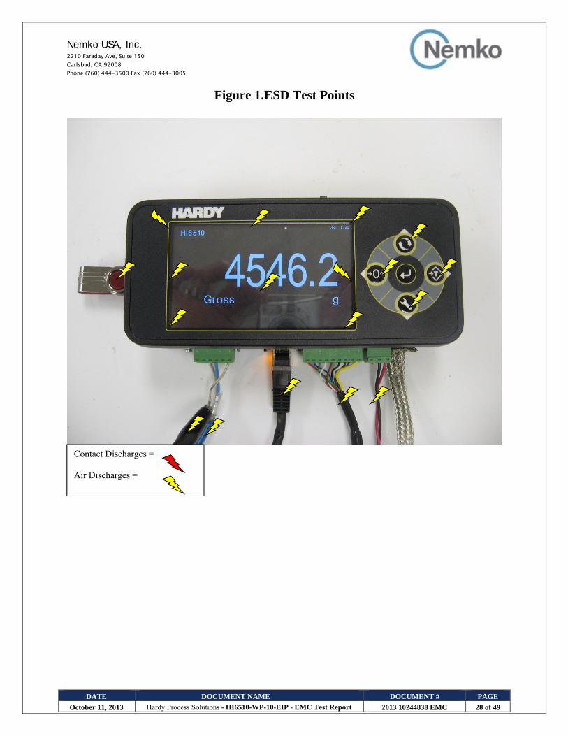
5.18.Electrostatic Discharge Immunity Test Results & Test Points
Electrostatic Discharge Immunity Test Client: Hardy Process Solutions Temperature: 23 C NEx #: 244838 Relative Humidity: 55 % EUT Name: Weight Processor Barometric Pressure: 100.5 kPa EUT Model: HI6510-WP-10-EIP Test Location ESD Room Governing Doc: EN61326-1 Test Engineer William Dey Basic Standard: IEC 61000-4-2 Date: 7 October 2013 Test Voltage: 24 VDC Photo:
TEST CONDITIONS Discharge Rep. Rate > 1 per second Number of Discharges > 10 per location Performance Criteria: A EUT Mode: Weight Processing during test, Susceptibility Requirement +/- 1.5 grams
CONTACT DISCHARGEVoltage: (+/- kV) 2 4
Location Comments Vertical Coupling Plane No susceptibility noted.
Horizontal Coupling Plane No susceptibility noted.
Contact Locations No susceptibility noted.
AIR DISCHARGEVoltage: (+/- kV) 2 4 8
Location Comments Air Locations No susceptibility noted.
“Spark” event(s) No Spark events. Compliant
Non-Compliant
ELECTRO STATIC DISCHARGE TEST EQUIPMENT Nemko ID Device Manufacturer Model Serial Number Cal Date Cal Due Date
811 Multimeter Fluke 111 78130057 20-Feb-2013 20-Feb-2014 818 ESD Gun Schaffner NSG-435 5111 27-Nov-2012 27-Nov-2013
E1044 Temp
Humidity Meter
Davis Instruments
7400 PE80513A01 06-Dec-2012 06-Dec-2013
Nemko USA, Inc. 2210 Faraday Ave, Suite 150 Carlsbad, CA 92008 Phone (760) 444-3500 Fax (760) 444-3005
DATE DOCUMENT NAME DOCUMENT # PAGE
October 11, 2013 Hardy Process Solutions - HI6510-WP-10-EIP - EMC Test Report 2013 10244838 EMC 28 of 49
Figure 1.ESD Test Points
Contact Discharges = Air Discharges =

Nemko USA, Inc. 2210 Faraday Ave, Suite 150 Carlsbad, CA 92008 Phone (760) 444-3500 Fax (760) 444-3005
DATE DOCUMENT NAME DOCUMENT # PAGE
October 11, 2013 Hardy Process Solutions - HI6510-WP-10-EIP - EMC Test Report 2013 10244838 EMC 29 of 49
Figure 2.ESD Test Points
Contact Discharges = Air Discharges =
Nemko USA, Inc. 2210 Faraday Ave, Suite 150 Carlsbad, CA 92008 Phone (760) 444-3500 Fax (760) 444-3005
DATE DOCUMENT NAME DOCUMENT # PAGE
October 11, 2013 Hardy Process Solutions - HI6510-WP-10-EIP - EMC Test Report 2013 10244838 EMC 30 of 49
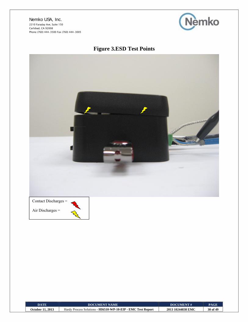
Figure 3.ESD Test Points
Contact Discharges = Air Discharges =

Nemko USA, Inc. 2210 Faraday Ave, Suite 150 Carlsbad, CA 92008 Phone (760) 444-3500 Fax (760) 444-3005
DATE DOCUMENT NAME DOCUMENT # PAGE
October 11, 2013 Hardy Process Solutions - HI6510-WP-10-EIP - EMC Test Report 2013 10244838 EMC 31 of 49
Figure 4.ESD Test Points
Contact Discharges = Air Discharges =

Nemko USA, Inc. 2210 Faraday Ave, Suite 150 Carlsbad, CA 92008 Phone (760) 444-3500 Fax (760) 444-3005
DATE DOCUMENT NAME DOCUMENT # PAGE
October 11, 2013 Hardy Process Solutions - HI6510-WP-10-EIP - EMC Test Report 2013 10244838 EMC 32 of 49
Figure 5.ESD Test Points
Contact Discharges = Air Discharges =

Nemko USA, Inc. 2210 Faraday Ave, Suite 150 Carlsbad, CA 92008 Phone (760) 444-3500 Fax (760) 444-3005
DATE DOCUMENT NAME DOCUMENT # PAGE
October 11, 2013 Hardy Process Solutions - HI6510-WP-10-EIP - EMC Test Report 2013 10244838 EMC 33 of 49
Figure 6.ESD Test Points
Contact Discharges = Air Discharges =

Nemko USA, Inc. 2210 Faraday Ave, Suite 150 Carlsbad, CA 92008 Phone (760) 444-3500 Fax (760) 444-3005
DATE DOCUMENT NAME DOCUMENT # PAGE
October 11, 2013 Hardy Process Solutions - HI6510-WP-10-EIP - EMC Test Report 2013 10244838 EMC 34 of 49
5.19.Radio Frequency Immunity Test Results
Radio Frequency Immunity Test Client: Hardy Process Solutions Temperature: 23 C NEx #: 244838 Relative Humidity: 55 % EUT Name: Weight Processor Barometric Pressure: 100.5 kPa EUT Model: HI6510-WP-10-EIP Test Location RFI Chamber Governing Doc: EN61326-1 Test Engineer William Dey Basic Standard: IEC 61000-4-3 Date: 3 October 2013 Test Voltage: 24 VDC Photo:
Test Conditions Test Level: 3 V/m Frequency Swept: 80 to 2700 MHz Selected Frequencies: N/A Modulation: 80 % Depth, 1 kHz AM Modulation Frequency Step: 1 % Dwell Time: 3 seconds Performance Criteria: A EUT Mode: Weight Processing during test, Susceptibility Requirement +/- 1.5 grams
Test Scans Accomplished Frequency (MHz) Antenna
Polarization Compliant Orientation
F: Front R: Rear SL: Side, Left SR: Side, Right
Comments
H V Y N
80-200 F No susceptibility noted 80-200 R No susceptibility noted. 80-200 SL No susceptibility noted. 80-200 SR No susceptibility noted.
200-1000 SR No susceptibility noted. 200-1000 SL No susceptibility noted. 200-1000 R No susceptibility noted. 200-1000 F No susceptibility noted.
1000-2700 F No susceptibility noted 1000-2700 R No susceptibility noted. 1000-2700 SL No susceptibility noted. 1000-2700 SR No susceptibility noted.
Additional Comments:
Compliant No susceptibility noted. Non-Compliant

Nemko USA, Inc. 2210 Faraday Ave, Suite 150 Carlsbad, CA 92008 Phone (760) 444-3500 Fax (760) 444-3005
DATE DOCUMENT NAME DOCUMENT # PAGE
October 11, 2013 Hardy Process Solutions - HI6510-WP-10-EIP - EMC Test Report 2013 10244838 EMC 35 of 49
Radio Frequency Immunity Test Equipment
Nemko ID Device Manufacturer Model Serial Number Cal Date Cal Due Date 372 Antenna, Dual Ridge Electro-Metrics RGA 25 2225 05-Nov-2012 05-Nov-2014 811 Multimeter Fluke 111 78130057 20-Feb-2013 20-Feb-2014
740 RF Amplifier Amplifier Research
500W1000M5 23680 N/R N/R
743 RF Amplifier Amplifier Research
200T1G3M3 (800 to 28
19649 N/R N/R
EA2466 Biconical Antenna EMCO 3109 9403-2801 N/R N/R
728 Microwave Horn
Antenna Amplifier Research
AT4002A (0.8MHz to
5GHz) 23811 N/R N/R
RENTED Signal Generator Agilent N9310A CN0115000228 6-Dec-2013 6-Dec-2014
Antennas
Nemko ID VSWR Manufacturer Model Serial Number Cal Date Cal Due Date
EA 2466 1.9:1 EMCO 3109 9403-2801 NCR NCR 728 2.0:1 Amplifier Research DC7140 23726 NCR NCR 372 2.0:1 Electro-Metrics RGA-25 2225 05-Nov-2012 05-Nov-2014

Nemko USA, Inc. 2210 Faraday Ave, Suite 150 Carlsbad, CA 92008 Phone (760) 444-3500 Fax (760) 444-3005
DATE DOCUMENT NAME DOCUMENT # PAGE
October 11, 2013 Hardy Process Solutions - HI6510-WP-10-EIP - EMC Test Report 2013 10244838 EMC 36 of 49
5.20.Electrical Fast Transient Burst Immunity Test Results Electrical Fast Transient Burst Immunity Test
Client Hardy Process Solutions Temperature 23 C NEx #: 244838 Relative Humidity 58 % EUT Name Weight Processor Barometric Pressure 100.6 kPa EUT Model HI6510-WP-10-EIP Test Location Ground Plane Governing Doc EN61326-1 Test Engineer William Dey Basic Standard IEC 61000-4-4 Date 4 October 2013 Test Voltage: 24 VDC Photo:
Test Conditions Power Port: DC Mains Highest Power Port Test Level: 2.0 kV Highest Signal Port Test Level: 1.0 kV Test Duration: 61 Seconds Burst: 5 kHz Performance Criteria: B EUT Mode: Weight Processing during test, Susceptibility Requirement +/- 1.5 grams Direct Injection Output Path DC Mains Test Level L1 L2 Comments
+/- 2.0kV Susceptibility noted. EUT loses communication with support CPU, yet still operates normally during and after the test
+/- 2.0kV Susceptibility noted. EUT loses communication with support CPU, yet still operates normally during and after the test
+/- 2.0kV Susceptibility noted. EUT loses communication with support CPU, yet still operates normally during and after the test
Cable Description (Clamp Injection)
+/- 1.0kV Load Cell Cable, shielded, 20ft
Susceptibility noted. EUT loses communication with support CPU, yet still operates normally during and after the test
+/- 1.0kV Ethernet RJ45 Cable, unshielded, 9ft
Susceptibility noted. EUT loses communication with support CPU, yet still operates normally during and after the test
+/- 1.0kV RS485 Cable, shielded, 20ft, to USB Cable, shielded, 3ft
Susceptibility noted. EUT loses communication with support CPU, yet still operates normally during and after the test
Additional Comments:
Compliant Susceptibility noted. EUT loses communication with support CPU, yet still operates normally during and after the test. EUT meets Class B Criteria.
Non-Compliant
EFT Test Equipment Nemko ID Device Manufacturer Model Serial Number Cal Date Cal Due Date
811 Multimeter Fluke 111 78130057 20-Feb-2013 20-Feb-2014845 Multi-Generator EMC Partner TRA2000 680 24-Jan-2013 24-Jan-2014
E1015 Capacitive
Coupling Clamp Haefely 093 506.1 083 874 -08 N/R N/R
945 Temp/Humidity
Indicator Davis Instruments 7400 PC00502A16 15-Jan-2013 15-Jan-2014

Nemko USA, Inc. 2210 Faraday Ave, Suite 150 Carlsbad, CA 92008 Phone (760) 444-3500 Fax (760) 444-3005
DATE DOCUMENT NAME DOCUMENT # PAGE
October 11, 2013 Hardy Process Solutions - HI6510-WP-10-EIP - EMC Test Report 2013 10244838 EMC 37 of 49
5.21. RF Conducted Common Mode Disturbance Immunity Test Results Client Hardy Process Solutions Temperature 23 ˚C NEx #: 244838 Relative Humidity 44 % EUT Name Weight Processor Barometric Pressure 100.6 kPa EUT Model HI6510-WP-10-EIP Test Location Ground Plane Governing Doc EN61326-1 Test Engineer William Dey Basic Standard IEC 61000-4-6 Date 7 October 2013 Test Voltage: 24 VDC Photo: Test Conditions Test Level: 3 V Modulation: 80 % Depth, 1 kHz AM Modulation Frequency Range: 0.15 to 80 MHz Selected Frequencies: N/A Step: 1 % Dwell Time: 3 seconds Performance Criteria: A EUT Mode: Weight Processing during test, Susceptibility Requirement +/- 1.5 grams
1 Injection Point DC Mains Injection Method: Clamp CDN Comments: No susceptibility noted.
2 Injection Point Load Cell Cable, shielded, 20ft Injection Method: Clamp CDN Comments: No susceptibility noted.
3 Injection Point Ethernet RJ45 Cable, unshielded, 9ft Injection Method: Clamp CDN Comments: No susceptibility noted.
4 Injection Point RS485 Cable, shielded, 20ft, to USB Cable, shielded, 3ft
Injection Method: Clamp CDN
Comments: No susceptibility noted. Additional Comments
Compliant No susceptibility noted.
Non-Compliant
Conducted Immunity Test Equipment Nemko
ID Device Manufacturer Model
Serial Number
Cal Date Cal Due Date
948 Signal Generator Hewlett Packard 8657A 3430U02365 10-Jan-2013 10-Jan-2014 628 CDN FCC FCC-801-M4-25 97-03 10-Jul-2013 10-Jul-2014 472 CDN FCC FCC-801-M2-25 24 17-Jul-2013 17-Jul-2014 913 Amplifier EIN 3100L 103 NCR NCR 810 Multimeter Fluke 111 77820242 10-Apr-2013 10-Apr-2014

Nemko USA, Inc. 2210 Faraday Ave, Suite 150 Carlsbad, CA 92008 Phone (760) 444-3500 Fax (760) 444-3005
DATE DOCUMENT NAME DOCUMENT # PAGE
October 11, 2013 Hardy Process Solutions - HI6510-WP-10-EIP - EMC Test Report 2013 10244838 EMC 38 of 49
5.22. Power Frequency Magnetic Field Immunity
Client: Hardy Process Solutions Temperature 23 ˚C NEx #: 244838 Relative Humidity 55 % EUT Name: Weight Processor Barometric Pressure 100.5 kPa EUT Model: HI6510-WP-10-EIP Test Location Ground Plane Governing Doc: EN61326-1 Test Engineer William Dey Basic Standard: IEC 61000-4-8 Date 7 October 2013 Test Voltage: 24 VDC Photo: Test Conditions Threat Level: 30 A/m Frequency: 50 and 60 Hz Duration Per Axis: 5 Minutes Performance Criteria: A EUT Mode: Weight Processing during test, Susceptibility Requirement +/- 1.5 grams
Compliant
Test Axis Y N Comments X No susceptibility noted. Y No susceptibility noted. Z No susceptibility noted.
Additional Comments:
Compliant No susceptibility noted. Non-Compliant
Power Frequency Magnetic Field Immunity Test Equipment Nemko
ID Device Manufacturer Model
Serial Number
Cal Date Cal Due Date
811 Multimeter Fluke 111 78130057 20-Feb-2013 20-Feb-2014
604 AC Power
System California
Instruments OMNI-3-18 with 5001i
-- 26-Feb-2013 26-Feb-2014
E1036 Large Magnetic
Coil Nemko N/A N/A N/R N/R
Rental Magnetic Field
Sensor Narda ETL-400 K-0033 23-Feb.2013 23-Feb.2014

Nemko USA, Inc. 2210 Faraday Ave, Suite 150 Carlsbad, CA 92008 Phone (760) 444-3500 Fax (760) 444-3005
DATE DOCUMENT NAME DOCUMENT # PAGE
October 11, 2013 Hardy Process Solutions - HI6510-WP-10-EIP - EMC Test Report 2013 10244838 EMC 39 of 49
Photograph 4. Conducted Emissions Test Configuration

Nemko USA, Inc. 2210 Faraday Ave, Suite 150 Carlsbad, CA 92008 Phone (760) 444-3500 Fax (760) 444-3005
DATE DOCUMENT NAME DOCUMENT # PAGE
October 11, 2013 Hardy Process Solutions - HI6510-WP-10-EIP - EMC Test Report 2013 10244838 EMC 40 of 49
Photograph 5. Radiated Emissions Test Configuration

Nemko USA, Inc. 2210 Faraday Ave, Suite 150 Carlsbad, CA 92008 Phone (760) 444-3500 Fax (760) 444-3005
DATE DOCUMENT NAME DOCUMENT # PAGE
October 11, 2013 Hardy Process Solutions - HI6510-WP-10-EIP - EMC Test Report 2013 10244838 EMC 41 of 49
Photograph 6. ESD Test Configuration

Nemko USA, Inc. 2210 Faraday Ave, Suite 150 Carlsbad, CA 92008 Phone (760) 444-3500 Fax (760) 444-3005
DATE DOCUMENT NAME DOCUMENT # PAGE
October 11, 2013 Hardy Process Solutions - HI6510-WP-10-EIP - EMC Test Report 2013 10244838 EMC 42 of 49
Photograph 7. Radio Frequency Immunity Test Configuration

Nemko USA, Inc. 2210 Faraday Ave, Suite 150 Carlsbad, CA 92008 Phone (760) 444-3500 Fax (760) 444-3005
DATE DOCUMENT NAME DOCUMENT # PAGE
October 11, 2013 Hardy Process Solutions - HI6510-WP-10-EIP - EMC Test Report 2013 10244838 EMC 43 of 49
Photograph 8. EFT Immunity Test Configuration

Nemko USA, Inc. 2210 Faraday Ave, Suite 150 Carlsbad, CA 92008 Phone (760) 444-3500 Fax (760) 444-3005
DATE DOCUMENT NAME DOCUMENT # PAGE
October 11, 2013 Hardy Process Solutions - HI6510-WP-10-EIP - EMC Test Report 2013 10244838 EMC 44 of 49
Photograph 9. RF Conducted Immunity Test Configuration

Nemko USA, Inc. 2210 Faraday Ave, Suite 150 Carlsbad, CA 92008 Phone (760) 444-3500 Fax (760) 444-3005
DATE DOCUMENT NAME DOCUMENT # PAGE
October 11, 2013 Hardy Process Solutions - HI6510-WP-10-EIP - EMC Test Report 2013 10244838 EMC 45 of 49
Photograph 10. Power Frequency Magnetic Field Immunity Test Configuration

Nemko USA, Inc. 2210 Faraday Ave, Suite 150 Carlsbad, CA 92008 Phone (760) 444-3500 Fax (760) 444-3005
DATE DOCUMENT NAME DOCUMENT # PAGE
October 11, 2013 Hardy Process Solutions - HI6510-WP-10-EIP - EMC Test Report 2013 10244838 EMC 46 of 49
APPENDIX A A. Radiated Emissions Measurement Uncertainties
1. Introduction ISO/IEC 17025:2005 and ANSI/NCSL Z540.3: 2006 require that all measurements contained in a test report be
“traceable”. “Traceability” is defined in the International Vocabulary of Basic and General Terms in Metrology
(ISO: 1993) as: “the property of the result of a measurement... whereby it can be related to stated references, usually
national or international standards, through an unbroken chain of comparisons, all having stated uncertainties”.
The purposes of this Appendix are to “state the Measurement Uncertainties” of the conducted emissions and
radiated emissions measurements contained in Section 5 of this Test Report, and to provide a practical explanation
of the meaning of these measurement uncertainties.
2. Statement of the Worst-Case Measurement Uncertainties for the Conducted and Radiated Emissions
Measurements Contained in This Test Report
Table 1: Worst-Case Expanded Uncertainty "U" of Measurement for a k=2 Coverage Factor
Worst-Case Expanded Uncertainty "U" of Measurement for a k=2 Coverage Factor Spectrum Analyzer and LISN 100 kHz – 30 MHz +/-2.8 dB Spectrum Analyzer and Telecom ISN 100 kHz – 30 MHz +/-1.38dB Spectrum Analyzer and Absorbing clamp 30 MHz-1000 MHz +/- 3.1 dB Spectrum Analyzer, Pre-amp, and Antenna 30 MHz-200 MHz +/-3.9 dB Spectrum Analyzer, Pre-amp, and Antenna 200 MHz-1000 MHz +/- 3.5 dB Spectrum Analyzer, Pre-amp, and Antenna 1 GHz - 18 GHz +/-2.6 dB
NOTES: 1. Applies to 3 and 10 meter measurement distances 2. Applies to all valid combinations of Transducers (i.e. LISNs, Line Voltage Probes, and Antennas, as appropriate) 3. Excludes the Repeatability of the EUT

Nemko USA, Inc. 2210 Faraday Ave, Suite 150 Carlsbad, CA 92008 Phone (760) 444-3500 Fax (760) 444-3005
DATE DOCUMENT NAME DOCUMENT # PAGE
October 11, 2013 Hardy Process Solutions - HI6510-WP-10-EIP - EMC Test Report 2013 10244838 EMC 47 of 49
3. Practical Explanation of the Meaning of Radiated Emissions Measurement Uncertainties In general, a “Statement of Measurement Uncertainty” means that with a certain (specified) confidence level, the
“true” value of a measurand will be between a (stated) upper bound and a (stated) lower bound.
In the specific case of EMC Measurements in this test report, the measurement uncertainties of the conducted
emissions measurements and the radiated emissions measurements have been calculated in accordance with the
method detailed in the following documents:
o ANSI Z540.2 (2002) Guide to the Expression of Uncertainty in Measurement o NIS 81:1994, The Treatment of Uncertainty in EMC Measurements (NAMAS, 1994) o NIST Technical Note 1297(1994), Guidelines for Evaluating and Expressing the Uncertainty of NIST
Measurement Results (NIST, 1994)
The calculation method used in these documents requires that the stated uncertainty of the measurements be
expressed as an “expanded uncertainty”, U, with a k=2 coverage factor. The practical interpretation of this method
of expressing measurement uncertainty is shown in the following example:
EXAMPLE: Assume that at 39.51 MHz, the (measured) radiated emissions level was equal to +26.5 dBuV/m, and that the +/- 2 standard deviations (i.e. 95% confidence level) measurement uncertainty was +/- 3.4 dB.

Nemko USA, Inc. 2210 Faraday Ave, Suite 150 Carlsbad, CA 92008 Phone (760) 444-3500 Fax (760) 444-3005
DATE DOCUMENT NAME DOCUMENT # PAGE
October 11, 2013 Hardy Process Solutions - HI6510-WP-10-EIP - EMC Test Report 2013 10244838 EMC 48 of 49
APPENDIX B B. Nemko USA, Inc. Test Equipment & Facilities Calibration Program
Nemko USA, Inc. operates a comprehensive Periodic Calibration Program in order to ensure the validity of all test
data. Nemko USA’s Periodic Calibration Program is fully compliant to the requirements of NVLAP Policy Guide
PG-1-1988, ANSI/NCSL Z540.3: 2006, ISO 10012:2003, ISO/IEC 17025:2005, and ISO-9000: 2000.Nemko USA,
Inc.’s calibrations program therefore meets or exceeds the US national commercial and military requirements [N.B.
ANSI/NCSL Z540-1-1994 replaced MIL-STD-45662A].
Specifically, all of Nemko USA’s primary reference standard devices (e.g. vector voltmeters, multimeters,
attenuators and terminations, RF power meters and their detector heads, oscilloscope mainframes and plug-ins,
spectrum analyzers, RF preselectors, quasi-peak adapters, interference analyzers, impulse generators, signal
generators and pulse/function generators, field-strength meters and their detector heads, etc.) and certain secondary
standard devices (e.g. RF Preamplifiers used in CISPR 11/22 and FCC Part 15/18 tests) are periodically recalibrated
by:
o A Nemko USA-approved independent (third party) metrology laboratory that uses NIST-traceable
standards and that is ISO Guide 25-accredited as a calibration laboratories by NIST; or,
o A Nemko USA-approved independent (third party) metrology laboratory that uses NIST-traceable
standards and that is ISO Guide 25-accredited as a calibration laboratory by another accreditation
body (such as A2LA) that is mutually recognized by NIST; or,
o A manufacturer of Measurement and Test Equipment (M&TE), if the manufacturer uses NIST-
traceable standards and is ISO Guide 25-accredited as calibration laboratory either by NIST or by
another accreditation body (such as A2LA) that is mutually recognized by NIST; or
o A manufacturer of M&TE (or by a Nemko USA-approved independent third party metrology
laboratory) that is not ISO Guide 25-accredited.(In these cases, Nemko USA conducts an annual audit
of the manufacturer or metrology laboratory for the purposes of proving traceabilty to NIST, ensuring
that adequate and repeatable calibration procedures are being applied, and verifying conformity with
the other requirements of ISO Guide 25).

Nemko USA, Inc. 2210 Faraday Ave, Suite 150 Carlsbad, CA 92008 Phone (760) 444-3500 Fax (760) 444-3005
DATE DOCUMENT NAME DOCUMENT # PAGE
October 11, 2013 Hardy Process Solutions - HI6510-WP-10-EIP - EMC Test Report 2013 10244838 EMC 49 of 49
In all cases, the entity performing the Calibration is required to furnish Nemko USA with a calibration test report
and/or certificate of calibration, and a “calibration sticker” on each item of M&TE that is successfully calibrated.
Calibration intervals are normally one year, except when the manufacture advises a shorter interval or if US
Government directives or client requirements demand a shorter interval. Items of instrumentation/related equipment
which fail during routine use, or which suffer visible mechanical damage (during use or while in transit), are
sidelined pending repair and recalibration.(Repairs are carried out either in-house [if minor] or by a Nemko USA-
approved independent [third party] metrology laboratory, or by the manufacturer of the item of M&TE).
Each antenna used for CISPR 11, CISPR 14, CISPR 22, and FCC Part 15 and Part 18 radiated emissions testing
(and for testing to the equivalent European Norms) is calibrated annually by either a NIST (or A2LA) ISO Standard
17025-Accredited third-party Antenna Calibration Laboratory or by the antenna’s OEM if the OEM is NIST or
A2LA ISO Standard 17025-accredited as an antenna calibration laboratory. The antenna calibrations are performed
using the methods specified in CISPR 16-1-4 or ANSI C63.5-2006, including the “Three-Antenna Method”. Certain
other kinds of antennas (e.g. magnetic-shielded loop antennas) are calibrated annually by either a NIST (or A2LA)
ISO Standard 17025-accredited third-party antenna calibration laboratory, or by the antenna’s OEM if the OEM is
NIST or A2LA ISO Standard 17025-accredited as an antenna calibration laboratory using the procedures specified
in the latest version of SAE ARP-958.
In accordance with FCC and other regulations, Nemko USA recalibrates its suite of antennas used for radiated
emissions tests on an annual basis. These calibrations are performed as a precursor to the FCC-required annual
revalidation of the Normalized Site Attenuation properties of Nemko USA’s 10-meter Semi-Anechoic chamber.
Nemko USA, Inc. uses the procedures given in CISPR 16-1-4 and, ANSI C63.4-2009 when performing the
normalized site attenuation measurements.