emc test report - matrixtelesol.com india pvt. ltd kalyani platina (phase 1) iii floor, sy. no 24...
TRANSCRIPT

UL India Pvt. Ltd
Kalyani Platina (Phase 1) III floor, Sy. No 24 “Underwriters Laboratories (UL) is an independent product
safety certification organization that has been testing products
and writing Standards for Safety for over a century.” Kundalahalli, K. R. Puram, Hobli, south Taluk
Whitefield Bangalore – 560066 INDIA
Tel: +91-80-41384400, Fax: + 91-80-41384400
Underwriters Laboratories Inc.
www.ul.com/emc
www.ul.co.in
Project: 13CA24421
File: MC16781
Report: 13CA24421
Date: July 15, 2013
Electromagnetic Compatibility Test Report
For NAVAN CNX
Copyright 2005 Underwriters Laboratories Inc.
UL India Pvt. Ltd. authorizes the above-named company to reproduce this Report provided it is
reproduced in its entirety.

Project Number: 13CA24421 File Number MC16781 Page 2 of 88
UL India Pvt. Ltd Kalyani Platina (Phase 1) III floor, Sy. No 24 Kundalahalli, K. R. Puram, Hobli, south Taluk
Whitefield Bangalore – 560066 INDIA Tel: +91-80-41384400, Fax: + 91-80-41384400
TEST REPORT DETAILS
Test Report No. 13CA24421
Tests Performed By: UL India Pvt. Ltd
Kundalahalli, K. R. Puram, Hobli, south Taluk
Whitefield Bangalore – 5600066 India
Tel: +91-80-41384400, Fax: + 91-80-41384400
Test site: UL India Pvt. Ltd
&
TARANG-Product Qualification & Compliance Planet,
Wipro Technologies, Survey No. 70, 77, 78/8A, Doddakannelli,
Sarjapur Road, Bangalore
Karnataka. Pin – 560035 INDIA
Applicant: Matrix Comsec Pvt. Ltd. Applicant Address: 394-GIDC, MAKARAPURA, VADODARA-390 010,
GUJARAT INDIA &
15, 19, 38 & 39 – GIDC, WAGHODIA, DIST: VADODARA-
391760, GUJRAT, INDIA.
Country: India
Test Report Date: 15-July-2013
Product Name: NAVAN CNX Product Type: IT
Product standards EN 55022/CISPR22-2010, EN 55024/CISPR24-2010, EN/IEC 61000-
3-3--2008, EN/IEC 61000-3-2 --2009, FCC Part-15 (Subpart B)
& Manufacturer Specified Test Program.
Model Number: NAVAN CNX
Sample Serial Number: NA
Sample Receive Date: 1-June-2013
Testing Start Date: 3-June-2013
Testing Complete Date: 4-July-2013
Overall Results: COMPLIED
UL India Pvt. Ltd. reports apply only to the specific samples tested under stated test conditions. All samples tested were in good operating
condition throughout the entire test program. It is the manufacturer's responsibility to assure that additional production units of this model are manufactured with identical electrical and mechanical components. UL India Pvt. Ltd. shall have no liability for any deductions, inferences or
generalizations drawn by the client or others from UL India Pvt. Ltd. issued reports.

Project Number: 13CA24421 File Number MC16781 Page 3 of 88
UL India Pvt. Ltd Kalyani Platina (Phase 1) III floor, Sy. No 24 Kundalahalli, K. R. Puram, Hobli, south Taluk
Whitefield Bangalore – 560066 INDIA Tel: +91-80-41384400, Fax: + 91-80-41384400
TEST SUMMARY
Test Result
Sr. No. Test requirements Results Verdict
Emissions
1 Main Terminal Disturbance Voltage Met Limit Complied
2 Radiated Emission Met Limit Complied
3 Harmonic Current Emission Met Limit Complied
4 Voltage Fluctuation and Flicker Met Limit Complied
Test requirements Acceptance Criteria Verdict
Immunity
5 Electrostatic Discharge (ESD) Criteria B Complied
6 RF Electromagnetic Field. Criteria A Complied
7 Fast Transients Immunity Criteria B Complied
8 Surges Immunity Criteria B Complied
9 RF Conducted Continuous Immunity Criteria A Complied
10 Power Frequency Magnetic Field Immunity Criteria A Complied
11 Voltage Dips & Short Interruption Criteria B & C Complied
The tests listed in the Summary of Testing section of this report have been performed and the results recorded by UL India Pvt.
Ltd. in accordance with the procedures stated in each test requirement and specification. The applicant determined the list of
tests performed were applicable to the Equipment under Test. As a result, the subject product has been verified to comply or
not comply as noted in the Summary of Testing with each test specification. The test results relate only to the items tested.
The equipment under test has
met the technical requirements
not met the technical requirements
Tested by
Manish Kumar
Reviewed by
Balaguru A
Conformity Assessment Services - 3014BNG Conformity Assessment Services - 3014BNG
UL India Pvt. Ltd. UL India Pvt. Ltd.

Project Number: 13CA24421 File Number MC16781 Page 4 of 88
UL India Pvt. Ltd Kalyani Platina (Phase 1) III floor, Sy. No 24 Kundalahalli, K. R. Puram, Hobli, south Taluk
Whitefield Bangalore – 560066 INDIA Tel: +91-80-41384400, Fax: + 91-80-41384400
Report Directory
1. EQUIPMENT UNDER TEST (EUT) ................................................................................................ 5
1.1 EQUIPMENT DESCRIPTION ........................................................................................................................... 5 1.2 EQUIPMENT MARKING PLATE ..................................................................................................................... 5 1.3 EQUIPMENT USED DURING TEST ................................................................................................................ 6 1.4 INPUT/OUTPUT PORTS ................................................................................................................................. 7 1.5 POWER INTERFACE: ..................................................................................................................................... 7 1.6 EUT INTERNAL OPERATING FREQUENCIES: ............................................................................................... 7
2. EUT OPERATION MODES: ............................................................................................................ 8
3. EUT CONFIGURATIONS: BLOCK DIAGRAM........................................................................... 8
4. PERFORMANCE CRITERIA .......................................................................................................... 9
4.1 GENERAL PERFORMANCE CRITERIA OF THE EN 55024/CISPR 24 ................................... 9
4.2 FUNCTIONS MONITORED DURING & AFTER IMMUNITY ................................................ 10
5. CONDUCTED DISTURBANCE (CONDUCTED EMISSION) .................................................. 11
5.1 MAINS TERMINAL DISTURBANCE VOLTAGE ................................................................. 11
5.2 TELECOMMUNICATION PORTS ............................................................................................... 21
6. RADIATED DISTURBANCE (RADIATED EMISSION) ........................................................... 37
7. HARMONIC CURRENT EMISSION ............................................................................................ 51
8. VOLTAGE FLUCTUATIONS AND FLICKER ........................................................................... 55
9. ELECTROSTATIC DISCHARGES (ESD) ................................................................................... 60
10. ELECTROMAGNETIC FIELD (RADIATED SUSCEPTIBILITY) ...................................... 65
11. ELECTRICAL FAST TRANSIENTS (EFT) / BURST............................................................. 69
12. SURGES ......................................................................................................................................... 74
13. CONTINUOUS CONDUCTED DISTURBANCES (CONDUCTED RF SUSCEPTIBILITY)
79
14. POWER-FREQUENCY MAGNETIC FIELDS ........................................................................ 83
15. VOLTAGE DIPS AND INTERRUPTIONS............................................................................... 86

Project Number: 13CA24421 File Number MC16781 Page 5 of 88
UL India Pvt. Ltd Kalyani Platina (Phase 1) III floor, Sy. No 24 Kundalahalli, K. R. Puram, Hobli, south Taluk
Whitefield Bangalore – 560066 INDIA Tel: +91-80-41384400, Fax: + 91-80-41384400
1. EQUIPMENT UNDER TEST (EUT)
1.1 Equipment Description
NAVAN CNX is a single box solution for all voice, data, wireless, mobility and messaging needs
of small businesses and branch offices with up 24 users. NAVAN CNX delivers enterprise-class
IP-PBX features, mobility, secure internet, wireless access, data networking, VPN, Firewall and
SMS Functionality from a compact and converged platform.
A true office-in-a-box, NAVAN CNX innovates the way businesses communicate and manage
infrastructure, so that they can lower operational costs and enhance collaboration with customers
and suppliers.
1.2 Equipment Marking Plate
NAVAN CNX

Project Number: 13CA24421 File Number MC16781 Page 6 of 88
UL India Pvt. Ltd Kalyani Platina (Phase 1) III floor, Sy. No 24 Kundalahalli, K. R. Puram, Hobli, south Taluk
Whitefield Bangalore – 560066 INDIA Tel: +91-80-41384400, Fax: + 91-80-41384400
1.3 Equipment Used During Test
Use* Product Type Manufacturer Model Comments
EUT Office-in-a-Box Matrix Comsec Pvt. Ltd. NAVAN CNX None
AE Ethernet Switch D-Link DES-1008A None
AE AC DC Adapter Matrix Comsec Pvt. Ltd. MSA4824D None
AE SLT Phone Matrix Comsec Pvt. Ltd. NEO10 None
* Note: EUT – Equipment Under Test, AE – Auxiliary/Associated Equipment, SIM – Simulator (Not
Subjected to Test)

Project Number: 13CA24421 File Number MC16781 Page 7 of 88
UL India Pvt. Ltd Kalyani Platina (Phase 1) III floor, Sy. No 24 Kundalahalli, K. R. Puram, Hobli, south Taluk
Whitefield Bangalore – 560066 INDIA Tel: +91-80-41384400, Fax: + 91-80-41384400
1.4 Input/output Ports
Port
# Name Type*
Cable
Max. >3m
Cable
Shielded Comments
1 Power Port DC NO NO NA
2 LAN TP NO NO NA
3 WAN TP YES NO NA
4 TWT/CO Port TP YES NO NA
5 SLT Port TP YES NO NA
Note:
*AC = AC Power Port DC = DC Power Port N/E = Non-Electrical
I/O = Signal Input or Output Port (Not Involved in Process Control)
TP = Telecommunication Ports
1.5 Power Interface:
Mode
#
Voltage
(V)
Current
(A)
Frequency
(DC/AC-Hz)
Phases
(#)
Comments
Rated Input- 100-240VAC,
(Adapter 24V, 2A DC)
1.6A 50-60Hz Single NA
Tested 230V AC, 0.159A 50Hz single NA
1.6 EUT Internal Operating Frequencies:
Frequency Description
500 MHz Clock Frequency
83.33 MHz SMC peripheral clock
2.4 to 2.6 GHz Wi-Fi Module

Project Number: 13CA24421 File Number MC16781 Page 8 of 88
UL India Pvt. Ltd Kalyani Platina (Phase 1) III floor, Sy. No 24 Kundalahalli, K. R. Puram, Hobli, south Taluk
Whitefield Bangalore – 560066 INDIA Tel: +91-80-41384400, Fax: + 91-80-41384400
2. EUT Operation Modes:
Mode # Description
1 EUT was tested in continuous dial mode.
3. EUT Configurations: Block Diagram
EUT
- - - - - - - - - - - - - - - - - - - - - - - - - - - - - - - - - - - - - - - - - - - - - - - -- - - - - - - - - -- - - - - - -- - - - - -- - -
-- - -
AE
SLT Phone SLT Phone
NAVAN CNX WAN LAN1 – LAN7 P1 P1 P3 P5 DC LAN2 – LAN8 P2 P2 P4 P6 Jack
P1 P2 . . . . P7 P8
ETHERNET SWITCH
Adapter 24V@ 2A

Project Number: 13CA24421 File Number MC16781 Page 9 of 88
UL India Pvt. Ltd Kalyani Platina (Phase 1) III floor, Sy. No 24 Kundalahalli, K. R. Puram, Hobli, south Taluk
Whitefield Bangalore – 560066 INDIA Tel: +91-80-41384400, Fax: + 91-80-41384400
4. Performance Criteria
4.1 General Performance Criteria of the EN 55024/CISPR 24 Criterion A
During and after the test the EUT shall continue to operate as intended without operator intervention. No
degradation of performance or loss of function is allowed below a minimum performance level specified by the
manufacturer when the EUT is used as intended. The performance level may be replaced by a permissible loss of
performance. If the minimum performance level or the permissible performance loss is not specified by the
manufacturer, then either of these may be derived from the product description and documentation, and by
what the user may reasonably expect from the EUT if used as intended.
Criterion B
After the test, the EUT shall continue to operate as intended without operator intervention. No degradation of
performance or loss of function is allowed, after the application of the phenomena below a performance level
specified by the manufacturer, when the EUT is used as intended. The performance level may be replaced by a
permissible loss of performance. During the test, degradation of performance is allowed. However, no change of
operating state or stored data is allowed to persist after the test. If the minimum performance level (or the
permissible performance loss) is not specified by the manufacturer, then either of these may be derived from the
product description and documentation, and by what the user may reasonably expect from the EUT if used as
intended.
Criterion C
During and after testing, a temporary loss of function is allowed, provided the function is self-recoverable, or can
be restored by the operation of the controls or cycling of the power to the EUT by the user in accordance with the
manufacturer’s instructions. Functions, and/or information stored in non-volatile memory, or protected by a battery
backup, shall not be lost.
Project Number: 13CA24421 File Number MC16781 Page 10 of 88
UL India Pvt. Ltd Kalyani Platina (Phase 1) III floor, Sy. No 24 Kundalahalli, K. R. Puram, Hobli, south Taluk
Whitefield Bangalore – 560066 INDIA Tel: +91-80-41384400, Fax: + 91-80-41384400
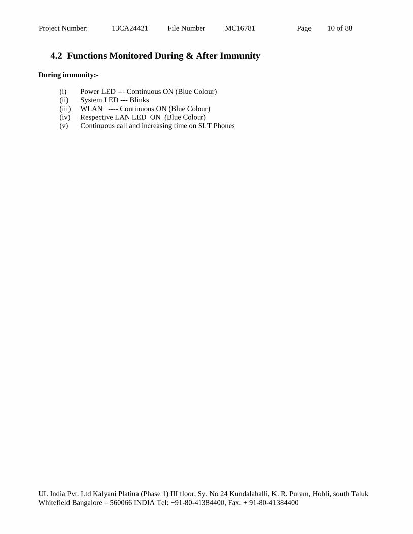
4.2 Functions Monitored During & After Immunity During immunity:-
(i) Power LED --- Continuous ON (Blue Colour)
(ii) System LED --- Blinks
(iii) WLAN ---- Continuous ON (Blue Colour)
(iv) Respective LAN LED ON (Blue Colour)
(v) Continuous call and increasing time on SLT Phones

Project Number: 13CA24421 File Number MC16781 Page 11 of 88
UL India Pvt. Ltd Kalyani Platina (Phase 1) III floor, Sy. No 24 Kundalahalli, K. R. Puram, Hobli, south Taluk
Whitefield Bangalore – 560066 INDIA Tel: +91-80-41384400, Fax: + 91-80-41384400
5. CONDUCTED DISTURBANCE (Conducted Emission)
5.1 MAINS TERMINAL DISTURBANCE VOLTAGE
A. AS per CISPR22/EN55022
Test CONDUCTED DISTURBANCES ( Conducted Emission)
Method Measurements were made on a ground plane. All power was connected to the system through
Artificial Mains Network (AMN). The AMN placed 0.8m from the boundary of the unit
under test and bounded to a ground reference plane. Conducted voltage measurement on mains
lines were made at the output of the AMN.
TEST ENVIRONMENT
Parameters recorded during the test Laboratory Ambient Temperature 26.7 °C
Relative Humidity 56.3 %
Frequency range on each side of line Measurement Point
Fully configured sample scanned
over the following frequency range
150kHz to 30MHz Mains Power Input
Basic Standard CISPR22: 2010
Limits - Class A
Frequency (MHz)
Limit (dBµV)
Quasi-Peak Results Average Results
0.15 – 0.5 79 Pass 66 Pass
0.5 -30 73 Pass 60 Pass
Supplementary Information: NA
Test Equipment Used
Description Manufacturer Model Identifier Cal. Date Cal. Due
EMI Test Receiver Rhode and Schwarz ESCI-3 101058 28-08-2012 28-08-2013
LISN Rhode and Schwarz ESH2-Z5 100277 07-08-2012 07-08-2013
Transient limiter Rhode and Schwarz ESH3-Z2 101153 07-08-2012 07-08-2013

Project Number: 13CA24421 File Number MC16781 Page 12 of 88
UL India Pvt. Ltd Kalyani Platina (Phase 1) III floor, Sy. No 24 Kundalahalli, K. R. Puram, Hobli, south Taluk
Whitefield Bangalore – 560066 INDIA Tel: +91-80-41384400, Fax: + 91-80-41384400
Figure 1: Conducted Emission Test Setup
AC Power Port

Project Number: 13CA24421 File Number MC16781 Page 13 of 88
UL India Pvt. Ltd Kalyani Platina (Phase 1) III floor, Sy. No 24 Kundalahalli, K. R. Puram, Hobli, south Taluk
Whitefield Bangalore – 560066 INDIA Tel: +91-80-41384400, Fax: + 91-80-41384400
Table 1: Test data for conducted emission on Line
Frequency
(MHz)
Emission Level
(dBµV)
(a)
Transducer
(dB)
(b)
Total Emission
(dBµV)
(c)
Limit Line
(dBµV)
(d)
Margin Level
(dB)
(e)
Quasi Peak measurement
0.150 43.31 9.82 53.13 79.00 -25.87
Average measurement
0.150 31.71 9.82 41.53 66.00 -24.47
5.610 27.17 5.08 32.25 60.00 -27.75
6.194 27.38 5.37 32.75 60.00 -27.25
16.834 26.37 8.31 34.68 60.00 -25.32
17.926 25.71 8.49 34.20 60.00 -25.80
Supplementary information:
Total Emission (c) = Emission Level (a) + Transducer (b)
Margin Level (e) = Total Emission (c) - Limit Line (d)
Table2: Test data for conducted emission on Neutral
Frequency
(MHz)
Emission Level
(dBµV)
(a)
Transducer
(dB)
(b)
Total Emission
(dBµV)
(c)
Limit Line
(dBµV)
(d)
Margin Level
(dB)
(e)
Quasi Peak measurement
0.150 43.27 9.82 53.09 79.00 -25.91
Average measurement
0.150 30.07 9.82 39.89 66.00 -26.11
5.686 27.54 5.12 32.66 60.00 -27.34
6.706 26.26 5.60 31.86 60.00 -28.14
17.422 26.61 8.41 35.02 60.00 -24.98
18.442 26.29 8.58 34.87 60.00 -25.13
Supplementary information:
Total Emission (c) = Emission Level (a) + Transducer (b)
Margin Level (e) = Total Emission (c) - Limit Line (d)

Project Number: 13CA24421 File Number MC16781 Page 14 of 88
UL India Pvt. Ltd Kalyani Platina (Phase 1) III floor, Sy. No 24 Kundalahalli, K. R. Puram, Hobli, south Taluk
Whitefield Bangalore – 560066 INDIA Tel: +91-80-41384400, Fax: + 91-80-41384400
Figure 2 : Graphical representation of conducted emissions
Conducted Emission plot –Measurement on Line

Project Number: 13CA24421 File Number MC16781 Page 15 of 88
UL India Pvt. Ltd Kalyani Platina (Phase 1) III floor, Sy. No 24 Kundalahalli, K. R. Puram, Hobli, south Taluk
Whitefield Bangalore – 560066 INDIA Tel: +91-80-41384400, Fax: + 91-80-41384400
Conducted Emission plot –Measurement on Neutral

Project Number: 13CA24421 File Number MC16781 Page 16 of 88
UL India Pvt. Ltd Kalyani Platina (Phase 1) III floor, Sy. No 24 Kundalahalli, K. R. Puram, Hobli, south Taluk
Whitefield Bangalore – 560066 INDIA Tel: +91-80-41384400, Fax: + 91-80-41384400
B. AS per FCC Part-15, Subpart B
Test MAINS TERMINAL DISTURBANCE VOLTAGE
Method Measurements were made on a ground plane. All power was connected to the system through
Line Impedance Stabilization Network (LISN). Conducted voltage measurements on mains
port were made at the output of the Line Impedance Stabilization Network (LISN).
TEST ENVIRONMENT
Parameters recorded during the test Laboratory Ambient Temperature 23 °C
Relative Humidity 55 %
Frequency range on each side of
line
Measurement Point
Fully configured sample scanned over
the following frequency range
150kHz to 30MHz A.C input Power of EUT
120V AC, 60Hz
Basic Standard FCC Part-15, Sub Part B : 2008
Limits : Class A
Frequency (MHz)
Limit (dBµV)
Quasi-Peak Results Average Results
0.15 to 0.50 79 Pass 66 Pass
0.5 to 30 73 Pass 60 Pass
Supplementary information: NA
Test Equipment Used
Description Manufacturer Model Identifier Cal. Date Cal. Due
EMI Test Receiver Rhode and Schwarz ESCI-3 101058 28-08-2012 28-08-2013
LISN Rhode and Schwarz ESH2-Z5 100277 07-08-2012 07-08-2013
Transient limiter Rhode and Schwarz ESH3-Z2 101153 07-08-2012 07-08-2013

Project Number: 13CA24421 File Number MC16781 Page 17 of 88
UL India Pvt. Ltd Kalyani Platina (Phase 1) III floor, Sy. No 24 Kundalahalli, K. R. Puram, Hobli, south Taluk
Whitefield Bangalore – 560066 INDIA Tel: +91-80-41384400, Fax: + 91-80-41384400
Figure 3: Conducted Emission Test Setup

Project Number: 13CA24421 File Number MC16781 Page 18 of 88
UL India Pvt. Ltd Kalyani Platina (Phase 1) III floor, Sy. No 24 Kundalahalli, K. R. Puram, Hobli, south Taluk
Whitefield Bangalore – 560066 INDIA Tel: +91-80-41384400, Fax: + 91-80-41384400
Table 3: Test data for conducted emission on Line
Frequency
(MHz)
Emission Level
(dBµV)
(a)
Transducer
(dB)
(b)
Total Emission
(dBµV)
(c)
Limit Line
(dBµV)
(d)
Margin Level
(dB)
(e)
Quasi Peak measurement
0.150 45.89 9.82 55.71 79.00 -23.29
Average measurement
0.150 31.17 9.82 40.99 66.00 -25.01
5.682 26.71 5.11 31.82 60.00 -28.18
6.266 27.05 5.40 32.45 60.00 -27.55
17.414 26.41 8.41 34.82 60.00 -25.18
18.434 26.33 8.58 34.91 60.00 -25.09
Supplementary information:
Total Emission (c) = Emission Level (a) + Transducer (b)
Margin Level (e) = Total Emission (c) - Limit Line (d)
Table 4: Test data for conducted emission on Neutral
Frequency
(MHz)
Emission Level
(dBµV)
(a)
Transducer
(dB)
(b)
Total Emission
(dBµV)
(c)
Limit Line
(dBµV)
(d)
Margin Level
(dB)
(e)
Quasi Peak measurement
0.166 42.58 9.82 52.4 79.00 -26.60
Average measurement
0.166 25.37 9.82 35.19 66.00 -30.81
5.65 13.54 5.10 18.64 60.00 -41.36
6.158 13.32 5.35 18.67 60.00 -41.33
16.838 12.38 8.31 20.69 60.00 -39.31
18.438 8.72 8.58 17.3 60.00 -42.70
Supplementary information:
Total Emission (c) = Emission Level (a) + Transducer (b)
Margin Level (e) = Total Emission (c) - Limit Line (d)

Project Number: 13CA24421 File Number MC16781 Page 19 of 88
UL India Pvt. Ltd Kalyani Platina (Phase 1) III floor, Sy. No 24 Kundalahalli, K. R. Puram, Hobli, south Taluk
Whitefield Bangalore – 560066 INDIA Tel: +91-80-41384400, Fax: + 91-80-41384400
Figure 4: Graphical representation of conducted emissions
Conducted Emission plot –Measurement on Line

Project Number: 13CA24421 File Number MC16781 Page 20 of 88
UL India Pvt. Ltd Kalyani Platina (Phase 1) III floor, Sy. No 24 Kundalahalli, K. R. Puram, Hobli, south Taluk
Whitefield Bangalore – 560066 INDIA Tel: +91-80-41384400, Fax: + 91-80-41384400
Conducted Emission plot –Measurement on Neutral

Project Number: 13CA24421 File Number MC16781 Page 21 of 88
UL India Pvt. Ltd Kalyani Platina (Phase 1) III floor, Sy. No 24 Kundalahalli, K. R. Puram, Hobli, south Taluk
Whitefield Bangalore – 560066 INDIA Tel: +91-80-41384400, Fax: + 91-80-41384400
5.2 TELECOMMUNICATION PORTS
Test TELECOMMUNICATION PORTS
Method Measurements were made on a ground plane. Data lines-FXS, WAN & LAN ports were
connected through Impedance Stabilization Network (ISN).
TEST ENVIRONMENT
Parameters recorded during the test Laboratory Ambient Temperature 23 °C
Relative Humidity 55 %
Frequency range on each side of
line
Measurement Point
Fully configured sample scanned over
the following frequency range
150kHz to 30MHz FXS, WAN, FXO & LAN
Basic Standard CISPR 22 : 2010
Limits – Class A
Frequency (MHz)
Voltage Limit (dBµV)
Quasi-Peak Results Average Results
0.15 to 0.5 97-87 Pass 84-74 Pass
0.5 to 30 87 Pass 74 Pass
Supplementary information: NA
Test Equipment Used
Description Manufacturer Model Identifier Cal. Date Cal. Due
EMI Test Receiver Rhode and Schwarz ESCI-3 101058 28-08-2012 28-08-2013
ISN Rhode and Schwarz ENY81 100081 09-11-2011 09-11-2013
Transient limiter Rhode and Schwarz ESH3-Z2 101153 07-08-2012 07-08-2013
EMI Test Receiver Rhode and Schwarz ESIB 40 10036 11.09.2012 11.09.2013
ISN TESEQ ISN T 800 28603 19.12.2012 19.12.2013
Pulse Limiter Rhode and Schwarz ESH3-Z2 0351-8810-54-
101260-WE NA NA

Project Number: 13CA24421 File Number MC16781 Page 22 of 88
UL India Pvt. Ltd Kalyani Platina (Phase 1) III floor, Sy. No 24 Kundalahalli, K. R. Puram, Hobli, south Taluk
Whitefield Bangalore – 560066 INDIA Tel: +91-80-41384400, Fax: + 91-80-41384400
Figure 5: Conducted Emission Test Setup for FXS 4
Voltage Measurement

Project Number: 13CA24421 File Number MC16781 Page 23 of 88
UL India Pvt. Ltd Kalyani Platina (Phase 1) III floor, Sy. No 24 Kundalahalli, K. R. Puram, Hobli, south Taluk
Whitefield Bangalore – 560066 INDIA Tel: +91-80-41384400, Fax: + 91-80-41384400
Table 5: Test data for conducted emission on FXS4
Frequency
(MHz)
Emission Level
(dBµV)
(a)
Transducer
(dB)
(b)
Total Emission
(dBµV)
(c)
Limit Line
(dBµV)
(d)
Margin Level
(dB)
(e)
Quasi Peak measurement
1.818 49.72 9.85 59.57 87.00 -27.43
Average measurement
0.162 59.36 10.23 69.59 83.36 -13.77
0.290 54.11 10.14 64.25 78.52 -14.27
0.366 53.05 10.10 63.15 76.59 -13.44
0.438 52.29 10.07 62.36 75.10 -12.74
0.510 52.50 10.05 62.55 74.00 -11.45
0.590 52.83 10.03 62.86 74.00 -11.14
0.874 51.89 9.97 61.86 74.00 -12.14
1.010 54.16 9.94 64.10 74.00 -9.90
1.178 53.23 9.92 63.15 74.00 -10.85
1.154 54.56 9.92 64.48 74.00 -9.52
Supplementary information:
Total Emission (c) = Emission Level (a) + Transducer (b)
Margin Level (e) = Total Emission (c) - Limit Line (d)

Project Number: 13CA24421 File Number MC16781 Page 24 of 88
UL India Pvt. Ltd Kalyani Platina (Phase 1) III floor, Sy. No 24 Kundalahalli, K. R. Puram, Hobli, south Taluk
Whitefield Bangalore – 560066 INDIA Tel: +91-80-41384400, Fax: + 91-80-41384400
Figure 6: Graphical representation of conducted emissions for FXS 4
Final measurement data

Project Number: 13CA24421 File Number MC16781 Page 25 of 88
UL India Pvt. Ltd Kalyani Platina (Phase 1) III floor, Sy. No 24 Kundalahalli, K. R. Puram, Hobli, south Taluk
Whitefield Bangalore – 560066 INDIA Tel: +91-80-41384400, Fax: + 91-80-41384400
Figure 7: Conducted Emission Test Setup for FXS 6
Voltage Measurement
Project Number: 13CA24421 File Number MC16781 Page 26 of 88
UL India Pvt. Ltd Kalyani Platina (Phase 1) III floor, Sy. No 24 Kundalahalli, K. R. Puram, Hobli, south Taluk
Whitefield Bangalore – 560066 INDIA Tel: +91-80-41384400, Fax: + 91-80-41384400
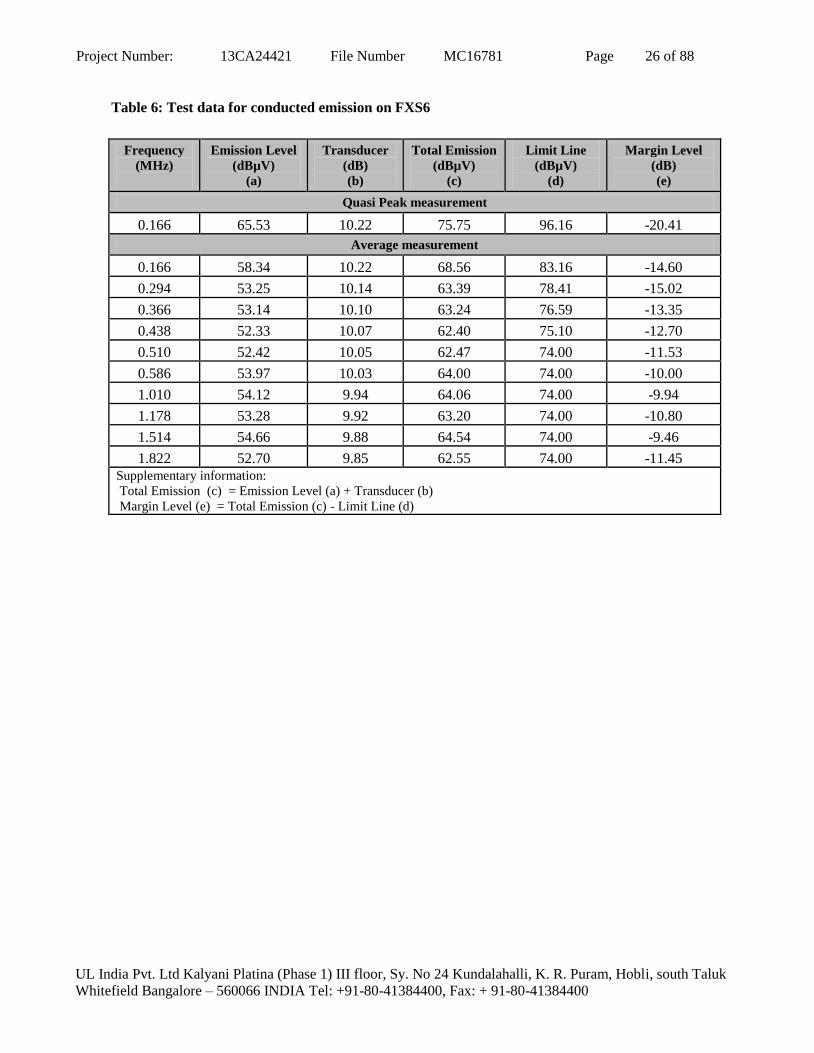
Table 6: Test data for conducted emission on FXS6
Frequency
(MHz)
Emission Level
(dBµV)
(a)
Transducer
(dB)
(b)
Total Emission
(dBµV)
(c)
Limit Line
(dBµV)
(d)
Margin Level
(dB)
(e)
Quasi Peak measurement
0.166 65.53 10.22 75.75 96.16 -20.41
Average measurement
0.166 58.34 10.22 68.56 83.16 -14.60
0.294 53.25 10.14 63.39 78.41 -15.02
0.366 53.14 10.10 63.24 76.59 -13.35
0.438 52.33 10.07 62.40 75.10 -12.70
0.510 52.42 10.05 62.47 74.00 -11.53
0.586 53.97 10.03 64.00 74.00 -10.00
1.010 54.12 9.94 64.06 74.00 -9.94
1.178 53.28 9.92 63.20 74.00 -10.80
1.514 54.66 9.88 64.54 74.00 -9.46
1.822 52.70 9.85 62.55 74.00 -11.45
Supplementary information:
Total Emission (c) = Emission Level (a) + Transducer (b)
Margin Level (e) = Total Emission (c) - Limit Line (d)

Project Number: 13CA24421 File Number MC16781 Page 27 of 88
UL India Pvt. Ltd Kalyani Platina (Phase 1) III floor, Sy. No 24 Kundalahalli, K. R. Puram, Hobli, south Taluk
Whitefield Bangalore – 560066 INDIA Tel: +91-80-41384400, Fax: + 91-80-41384400
Figure 8: Graphical representation of conducted emissions for FXS 6
Final measurement data

Project Number: 13CA24421 File Number MC16781 Page 28 of 88
UL India Pvt. Ltd Kalyani Platina (Phase 1) III floor, Sy. No 24 Kundalahalli, K. R. Puram, Hobli, south Taluk
Whitefield Bangalore – 560066 INDIA Tel: +91-80-41384400, Fax: + 91-80-41384400
Figure 7: Conducted Emission Test Setup for FXO
Voltage Measurement

Project Number: 13CA24421 File Number MC16781 Page 29 of 88
UL India Pvt. Ltd Kalyani Platina (Phase 1) III floor, Sy. No 24 Kundalahalli, K. R. Puram, Hobli, south Taluk
Whitefield Bangalore – 560066 INDIA Tel: +91-80-41384400, Fax: + 91-80-41384400
Table 6: Test data for conducted emission on FXO
Frequency
(MHz)
Emission Level
(dBµV)
(a)
Transducer
(dB)
(b)
Total Emission
(dBµV)
(c)
Limit Line
(dBµV)
(d)
Margin Level
(dB)
(e)
Quasi Peak measurement
0.500 43.40 19.83 63.22 87.00 -23.78
0.720 44.90 19.76 64.66 87.00 -22.34
0.800 45.12 19.77 64.89 87.00 -22.11
0.870 44.96 19.75 64.71 87.00 -22.29
0.940 43.78 19.76 63.54 87.00 -23.46
1.01 45.15 19.78 64.93 87.00 -22.07
1.09 44.65 19.78 64.42 87.00 -22.58
1.160 45.08 19.78 64.86 87.00 -22.14
1.170 45.84 19.78 65.63 87.00 -21.37
1.230 44.31 19.78 64.09 87.00 -22.91
Average measurement
0.500 41.17 19.83 61.00 74.00 -13.00
0.720 44.12 19.76 63.88 74.00 -10.12
0.800 44.27 19.76 64.03 74.00 -9.97
0.870 44.21 19.75 63.97 74.00 -10.03
0.940 42.99 19.76 62.75 74.00 -11.25
1.010 44.12 19.78 63.90 74.00 -10.10
1.090 44.20 19.78 63.97 74.00 -10.03
1.160 44.52 19.78 64.30 74.00 -9.70
1.170 45.10 19.78 64.88 74.00 -9.12
1.230 43.72 19.78 63.50 74.00 -10.50
Supplementary information:
Total Emission (c) = Emission Level (a) + Transducer (b)
Margin Level (e) = Total Emission (c) - Limit Line (d)

Project Number: 13CA24421 File Number MC16781 Page 30 of 88
UL India Pvt. Ltd Kalyani Platina (Phase 1) III floor, Sy. No 24 Kundalahalli, K. R. Puram, Hobli, south Taluk
Whitefield Bangalore – 560066 INDIA Tel: +91-80-41384400, Fax: + 91-80-41384400
Figure 8: Graphical representation of conducted emissions for FXO
Final measurement data
Peak Measurement
Average Measurement

Project Number: 13CA24421 File Number MC16781 Page 31 of 88
UL India Pvt. Ltd Kalyani Platina (Phase 1) III floor, Sy. No 24 Kundalahalli, K. R. Puram, Hobli, south Taluk
Whitefield Bangalore – 560066 INDIA Tel: +91-80-41384400, Fax: + 91-80-41384400
Figure 9: Conducted Emission Test Setup for WAN
Voltage Measurement
Project Number: 13CA24421 File Number MC16781 Page 32 of 88
UL India Pvt. Ltd Kalyani Platina (Phase 1) III floor, Sy. No 24 Kundalahalli, K. R. Puram, Hobli, south Taluk
Whitefield Bangalore – 560066 INDIA Tel: +91-80-41384400, Fax: + 91-80-41384400
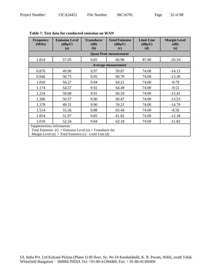
Table 7: Test data for conducted emission on WAN
Frequency
(MHz)
Emission Level
(dBµV)
(a)
Transducer
(dB)
(b)
Total Emission
(dBµV)
(c)
Limit Line
(dBµV)
(d)
Margin Level
(dB)
(e)
Quasi Peak measurement
1.814 57.05 9.85 66.90 87.00 -20.10
Average measurement
0.870 49.90 9.97 59.87 74.00 -14.13
0.946 50.75 9.95 60.70 74.00 -13.30
1.010 54.27 9.94 64.21 74.00 -9.79
1.174 54.57 9.92 64.49 74.00 -9.51
1.234 50.68 9.91 60.59 74.00 -13.41
1.306 50.57 9.90 60.47 74.00 -13.53
1.378 49.31 9.90 59.21 74.00 -14.79
1.514 55.56 9.88 65.44 74.00 -8.56
1.814 51.97 9.85 61.82 74.00 -12.18
2.018 52.34 9.84 62.18 74.00 -11.82
Supplementary information:
Total Emission (c) = Emission Level (a) + Transducer (b)
Margin Level (e) = Total Emission (c) - Limit Line (d)

Project Number: 13CA24421 File Number MC16781 Page 33 of 88
UL India Pvt. Ltd Kalyani Platina (Phase 1) III floor, Sy. No 24 Kundalahalli, K. R. Puram, Hobli, south Taluk
Whitefield Bangalore – 560066 INDIA Tel: +91-80-41384400, Fax: + 91-80-41384400
Figure 10: Graphical representation of conducted emissions for WAN
Final measurement data

Project Number: 13CA24421 File Number MC16781 Page 34 of 88
UL India Pvt. Ltd Kalyani Platina (Phase 1) III floor, Sy. No 24 Kundalahalli, K. R. Puram, Hobli, south Taluk
Whitefield Bangalore – 560066 INDIA Tel: +91-80-41384400, Fax: + 91-80-41384400
Figure 11: Conducted Emission Test Setup for LAN

Project Number: 13CA24421 File Number MC16781 Page 35 of 88
UL India Pvt. Ltd Kalyani Platina (Phase 1) III floor, Sy. No 24 Kundalahalli, K. R. Puram, Hobli, south Taluk
Whitefield Bangalore – 560066 INDIA Tel: +91-80-41384400, Fax: + 91-80-41384400
Table 8: Test data for conducted emission on LAN
Frequency
(MHz)
Emission Level
(dBµV)
(a)
Transducer
(dB)
(b)
Total Emission
(dBµV)
(c)
Limit Line
(dBµV)
(d)
Margin Level
(dB)
(e)
Quasi Peak measurement
1.814 56.30 9.85 66.15 87.00 -20.85
Average measurement
0.870 48.13 9.97 58.10 74.00 -15.90
0.946 50.74 9.95 60.69 74.00 -13.31
1.010 54.11 9.94 64.05 74.00 -9.95
1.174 54.40 9.92 64.32 74.00 -9.68
1.234 48.77 9.91 58.68 74.00 -15.32
1.306 48.07 9.90 57.97 74.00 -16.03
1.378 46.24 9.90 56.14 74.00 -17.86
1.514 55.84 9.88 65.72 74.00 -8.28
1.814 50.75 9.85 60.60 74.00 -13.40
2.018 52.67 9.84 62.51 74.00 -11.49
Supplementary information:
Total Emission (c) = Emission Level (a) + Transducer (b)
Margin Level (e) = Total Emission (c) - Limit Line (d)

Project Number: 13CA24421 File Number MC16781 Page 36 of 88
UL India Pvt. Ltd Kalyani Platina (Phase 1) III floor, Sy. No 24 Kundalahalli, K. R. Puram, Hobli, south Taluk
Whitefield Bangalore – 560066 INDIA Tel: +91-80-41384400, Fax: + 91-80-41384400
Figure 12: Graphical representation of conducted emissions for LAN
Final measurement data
Project Number: 13CA24421 File Number MC16781 Page 37 of 88
UL India Pvt. Ltd Kalyani Platina (Phase 1) III floor, Sy. No 24 Kundalahalli, K. R. Puram, Hobli, south Taluk
Whitefield Bangalore – 560066 INDIA Tel: +91-80-41384400, Fax: + 91-80-41384400
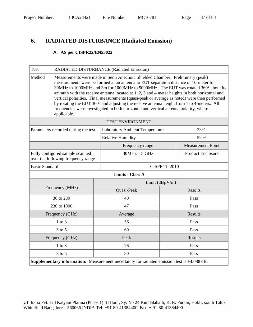
6. RADIATED DISTURBANCE (Radiated Emission)
A. AS per CISPR22/EN55022
Test RADIATED DISTURBANCE (Radiated Emission)
Method Measurements were made in Semi Anechoic Shielded Chamber. Preliminary (peak)
measurements were performed at an antenna to EUT separation distance of 10-meter for
30MHz to 1000MHz and 3m for 1000MHz to 5000MHz. The EUT was rotated 360° about its
azimuth with the receive antenna located at 1, 2, 3 and 4 meter heights in both horizontal and
vertical polarities. Final measurements (quasi-peak or average as noted) were then performed
by rotating the EUT 360° and adjusting the receive antenna height from 1 to 4-meters. All
frequencies were investigated in both horizontal and vertical antenna polarity, where
applicable.
TEST ENVIRONMENT
Parameters recorded during the test Laboratory Ambient Temperature 23°C
Relative Humidity 52 %
Frequency range Measurement Point
Fully configured sample scanned
over the following frequency range
30MHz – 5 GHz Product Enclosure
Basic Standard CISPR11: 2010
Limits - Class A
Frequency (MHz)
Limit (dBµV/m)
Quasi-Peak Results
30 to 230 40 Pass
230 to 1000 47 Pass
Frequency (GHz) Average Results
1 to 3 56 Pass
3 to 5 60 Pass
Frequency (GHz) Peak Results
1 to 3 76 Pass
3 to 5 80 Pass
Supplementary information: Measurement uncertainty for radiated emission test is ±4.088 dB.

Project Number: 13CA24421 File Number MC16781 Page 38 of 88
UL India Pvt. Ltd Kalyani Platina (Phase 1) III floor, Sy. No 24 Kundalahalli, K. R. Puram, Hobli, south Taluk
Whitefield Bangalore – 560066 INDIA Tel: +91-80-41384400, Fax: + 91-80-41384400
Test Equipment Used
Description Manufacturer Model Identifier Cal. Date Cal. Due
EMI Test Receiver R&S ESU08 100324 31-01-2013 31-01-2014
Hybrid log periodic Antenna TDK RF solution Inc. HLP-3003C 130334 21-03-2013 21-03-2014
TDK Shielded chamber TDK RF Solution Inc. - - - -
Figure 13: Photo of Radiated emission test setup
Frequency Range : 30 MHz to 1 GHz

Project Number: 13CA24421 File Number MC16781 Page 39 of 88
UL India Pvt. Ltd Kalyani Platina (Phase 1) III floor, Sy. No 24 Kundalahalli, K. R. Puram, Hobli, south Taluk
Whitefield Bangalore – 560066 INDIA Tel: +91-80-41384400, Fax: + 91-80-41384400
Frequency Range : 1 GHz to 5 GHz

Project Number: 13CA24421 File Number MC16781 Page 40 of 88
UL India Pvt. Ltd Kalyani Platina (Phase 1) III floor, Sy. No 24 Kundalahalli, K. R. Puram, Hobli, south Taluk
Whitefield Bangalore – 560066 INDIA Tel: +91-80-41384400, Fax: + 91-80-41384400
Table 9: Test data for Radiated emission (Frequency Range: 30 MHz to 1 GHz)
Freq Pol EUT Ttbl
Agl Twr Ht
(QP)
Trace
(a)
Cable
Loss
(b)
Transducer
(c)
Preamp
(d)
(QP) EMI
(e)
Limit
(f)
(QP)
Margin
(g)
(MHz) (deg) (cm) dB(µV) (dB) (dB) (dB) dB(µV/m) dB(µV/m) (dB)
39.52 V 202.40 133.00 47.65 1.30 9.43 32.22 26.15 40.00 -13.85
42.95 V 266.80 100.00 49.07 1.33 10.07 32.25 28.22 40.00 -11.78
55.90 V 16.60 119.00 47.84 1.50 9.25 32.23 26.36 40.00 -13.64
60.22 V 68.50 328.00 51.91 1.54 9.14 31.96 30.64 40.00 -9.36
60.82 V 18.80 323.00 51.08 1.56 9.20 32.30 29.54 40.00 -10.46
62.02 V 323.90 309.00 47.46 1.60 9.33 32.05 26.33 40.00 -13.67
77.19 V 53.00 400.00 43.94 1.79 9.11 32.49 22.34 40.00 -17.66
98.43 V 169.90 216.00 47.69 1.99 8.12 32.31 25.49 40.00 -14.51
150.00 H 213 364.00 46.04 2.41 11.17 32.08 27.54 40.00 -12.46
250.02 H 73.50 275.00 49.64 3.09 12.64 32.52 32.84 47.00 -14.16
250.01 V 0.00 103.00 55.43 3.09 12.64 32.52 38.63 47.00 -8.37
500.04 H 111.70 183.00 44.09 4.34 18.14 32.17 34.40 47.00 -12.60
Supplementary information:
Margin (g) = QP Level (e) – Limit (f)
QP Level (e) = [Meter reading (a) + cable loss (b) + Antenna Factor (c) – Preamp (d)]
Table 10: Test data for Radiated emission (Frequency Range: 1 GHz to 5 GHz)
Freq Pol EUT Ttbl
Agl Twr Ht
(AVG)
Trace
(a)
Cable
Loss
(b)
Transducer
(c)
Preamp
(d)
(QP) EMI
(e)
Limit
(f)
(QP)
Margin
(g)
(MHz) (deg) (cm) dB(µV) (dB) (dB) (dB) dB(µV/m) dB(µV/m) (dB)
2415.46 H 130.70 100.00 48.18 1.89 27.26 34.08 43.24 56.00 -12.76
2412.50 H 179.90 100.00 46.10 1.89 27.25 34.00 41.24 56.00 -14.76
2412.95 V 130.90 100.00 57.82 1.89 27.25 34.01 52.95 56.00 -3.05
2415.65 V 131.10 100.00 54.86 1.89 27.26 34.08 49.92 56.00 -6.08
Supplementary information:
Margin (g) = QP Level (e) – Limit (f)
QP Level (e) = [Meter reading (a) + cable loss (b) + Antenna Factor (c) – Preamp (d)]

Project Number: 13CA24421 File Number MC16781 Page 41 of 88
UL India Pvt. Ltd Kalyani Platina (Phase 1) III floor, Sy. No 24 Kundalahalli, K. R. Puram, Hobli, south Taluk
Whitefield Bangalore – 560066 INDIA Tel: +91-80-41384400, Fax: + 91-80-41384400
Figure 14: Graphical representation of Radiated emissions
Horizontal Polarization
Frequency Range: 30 MHz to 1 GHz

Project Number: 13CA24421 File Number MC16781 Page 42 of 88
UL India Pvt. Ltd Kalyani Platina (Phase 1) III floor, Sy. No 24 Kundalahalli, K. R. Puram, Hobli, south Taluk
Whitefield Bangalore – 560066 INDIA Tel: +91-80-41384400, Fax: + 91-80-41384400
Vertical Polarization
Frequency Range: 30 MHz to 1 GHz

Project Number: 13CA24421 File Number MC16781 Page 43 of 88
UL India Pvt. Ltd Kalyani Platina (Phase 1) III floor, Sy. No 24 Kundalahalli, K. R. Puram, Hobli, south Taluk
Whitefield Bangalore – 560066 INDIA Tel: +91-80-41384400, Fax: + 91-80-41384400
Horizontal Polarization
Peak Measurement
Frequency Range: 1 GHz to 5 GHz

Project Number: 13CA24421 File Number MC16781 Page 44 of 88
UL India Pvt. Ltd Kalyani Platina (Phase 1) III floor, Sy. No 24 Kundalahalli, K. R. Puram, Hobli, south Taluk
Whitefield Bangalore – 560066 INDIA Tel: +91-80-41384400, Fax: + 91-80-41384400
Vertical Polarization
Peak Measurement
Frequency Range: 1 GHz to 5 GHz

Project Number: 13CA24421 File Number MC16781 Page 45 of 88
UL India Pvt. Ltd Kalyani Platina (Phase 1) III floor, Sy. No 24 Kundalahalli, K. R. Puram, Hobli, south Taluk
Whitefield Bangalore – 560066 INDIA Tel: +91-80-41384400, Fax: + 91-80-41384400
Horizontal Polarization
Average Measurement
Frequency Range: 1 GHz to 5 GHz
Project Number: 13CA24421 File Number MC16781 Page 46 of 88
UL India Pvt. Ltd Kalyani Platina (Phase 1) III floor, Sy. No 24 Kundalahalli, K. R. Puram, Hobli, south Taluk
Whitefield Bangalore – 560066 INDIA Tel: +91-80-41384400, Fax: + 91-80-41384400
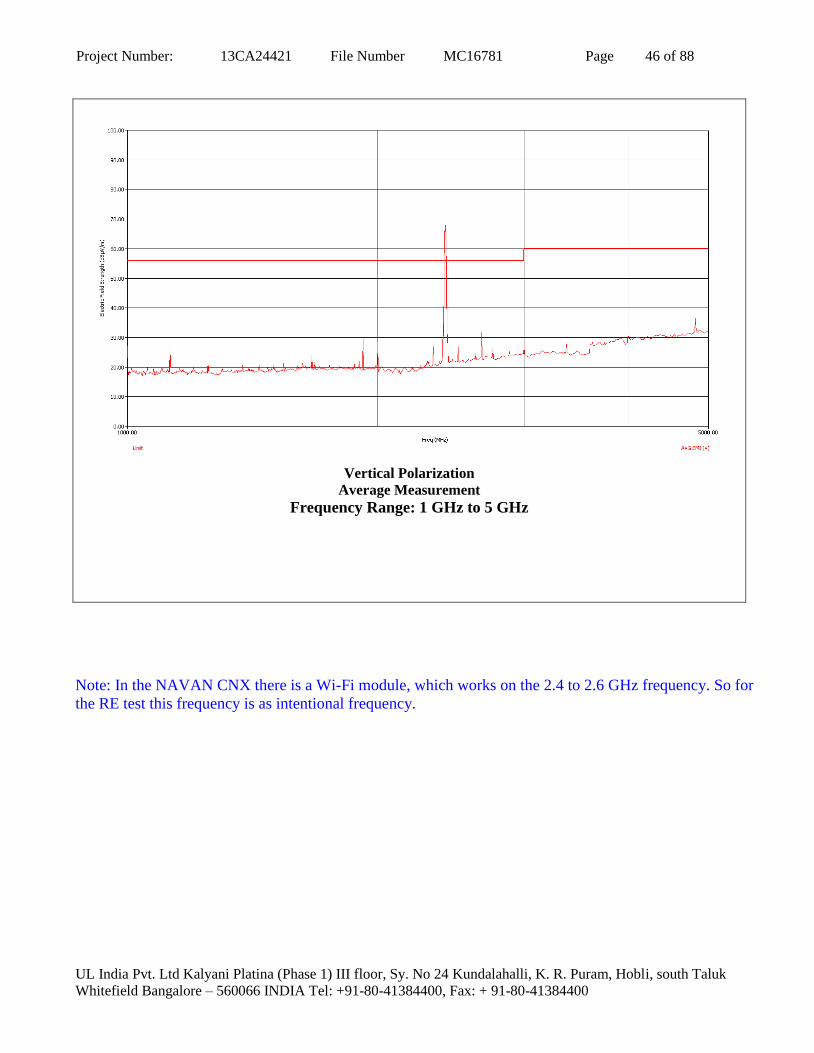
Vertical Polarization
Average Measurement
Frequency Range: 1 GHz to 5 GHz
Note: In the NAVAN CNX there is a Wi-Fi module, which works on the 2.4 to 2.6 GHz frequency. So for
the RE test this frequency is as intentional frequency.

Project Number: 13CA24421 File Number MC16781 Page 47 of 88
UL India Pvt. Ltd Kalyani Platina (Phase 1) III floor, Sy. No 24 Kundalahalli, K. R. Puram, Hobli, south Taluk
Whitefield Bangalore – 560066 INDIA Tel: +91-80-41384400, Fax: + 91-80-41384400
B. AS Per FCC Part 15, sub part B
Test RADIATED DISTURBANCE (Radiated Emission)
Method Measurements were made in Anechoic Shielded Chamber that complies to FCC Part 15.
Preliminary (peak) measurements were performed at an antenna to EUT separation distance of
10-meter. The EUT was rotated 360° about its azimuth with the receive antenna located at 1,
2, 3 and 4 meter heights in both horizontal and vertical polarities. Final measurements (quasi-
peak or average as noted) were then performed by rotating the EUT 360° and adjusting the
receive antenna height from 1 to 4-meters. All frequencies were investigated in both
horizontal and vertical antenna polarity, where applicable.
TEST ENVIRONMENT
Parameters recorded during the test Laboratory Ambient Temperature 23°C
Relative Humidity 55 %
Frequency range Measurement Point
Fully configured sample scanned over
the following frequency range
30MHz – 1GHz Product Enclosure
Basic Standard FCC Part-15, Sub Part B : 2008
Limits : Class A – Section 15.109 (b)
Frequency (MHz)
Limit dB(µV/m)
Quasi-Peak Results
30 to 88 39.08 Pass
88 to 216 43.52 Pass
216 to 960 46.44 Pass
960 to 1000 49.54 Pass
Supplementary information: NA
Test Equipment Used
Description Manufacturer Model Identifier Cal. Date Cal. Due
EMI Test Receiver R&S ESU08 100324 31-01-2013 31-01-2014
Hybrid log periodic Antenna TDK RF solution Inc. HLP-3003C 130334 21-03-2013 21-03-2014
TDK Shielded chamber TDK RF Solution Inc. - - - -

Project Number: 13CA24421 File Number MC16781 Page 48 of 88
UL India Pvt. Ltd Kalyani Platina (Phase 1) III floor, Sy. No 24 Kundalahalli, K. R. Puram, Hobli, south Taluk
Whitefield Bangalore – 560066 INDIA Tel: +91-80-41384400, Fax: + 91-80-41384400
Table 11: Test data for Radiated emission
Frequency Range: 30 MHz to 1 GHz
Freq Pol EUT Ttbl
Agl Twr Ht
(QP)
Trace
(a)
Cable
Loss
(b)
Transducer
(c)
Preamp
(d)
(QP) EMI
(e)
Limit
(f)
(QP)
Margin
(g)
(MHz) (deg) (cm) dB(µV) (dB) (dB) (dB) dB(µV/m) dB(µV/m) (dB)
39.52 V 202.40 133.00 47.65 1.30 9.43 32.22 26.15 39.08 -12.93
42.95 V 266.80 100.00 49.07 1.33 10.07 32.25 28.22 39.08 -10.86
55.90 V 16.60 119.00 47.84 1.50 9.25 32.23 26.36 39.08 -12.72
60.22 V 68.50 328.00 51.91 1.54 9.14 31.96 30.64 39.08 -8.44
60.82 V 18.80 323.00 51.08 1.56 9.20 32.30 29.54 39.08 -9.54
62.02 V 323.90 309.00 47.46 1.60 9.33 32.05 26.33 39.08 -12.75
77.19 V 53.30 400.00 43.94 1.79 9.11 32.49 22.34 39.08 -16.74
98.43 V 169.90 216.00 47.69 1.99 8.12 32.31 25.49 43.52 -18.03
150.00 H 213.30 364.00 46.04 2.41 11.17 32.08 27.54 43.52 -15.98
250.02 H 73.50 275.00 49.64 3.09 12.64 32.52 32.84 46.44 -13.60
250.01 V 0.00 103.00 55.43 3.09 12.64 32.52 38.63 46.44 -7.81
500.04 H 111.70 183.00 44.09 4.34 18.14 32.17 34.40 46.44 -12.04
Supplementary information:
Margin (g) = QP Level (e) – Limit (f)
QP Level (e) = [Meter reading (a) + cable loss (b) + Antenna Factor (c) – Preamp (d)]

Project Number: 13CA24421 File Number MC16781 Page 49 of 88
UL India Pvt. Ltd Kalyani Platina (Phase 1) III floor, Sy. No 24 Kundalahalli, K. R. Puram, Hobli, south Taluk
Whitefield Bangalore – 560066 INDIA Tel: +91-80-41384400, Fax: + 91-80-41384400
Figure 15: Graphical representation of Radiated emissions
Horizontal Polarization

Project Number: 13CA24421 File Number MC16781 Page 50 of 88
UL India Pvt. Ltd Kalyani Platina (Phase 1) III floor, Sy. No 24 Kundalahalli, K. R. Puram, Hobli, south Taluk
Whitefield Bangalore – 560066 INDIA Tel: +91-80-41384400, Fax: + 91-80-41384400
Vertical Polarization

Project Number: 13CA24421 File Number MC16781 Page 51 of 88
UL India Pvt. Ltd Kalyani Platina (Phase 1) III floor, Sy. No 24 Kundalahalli, K. R. Puram, Hobli, south Taluk
Whitefield Bangalore – 560066 INDIA Tel: +91-80-41384400, Fax: + 91-80-41384400
7. HARMONIC CURRENT EMISSION
TEST: Limits of harmonics of current (IEC 61000-3-2)
Method This test consists on the measurement of harmonics components of the input current which may be
produced by equipment having an input current up to and including 16 A per phase, and intended to
be connected to public low-voltage distribution systems. The equipment is tested under specified conditions of operation.
TEST ENVIRONMENT
Parameters recorded during the test
Laboratory Ambient Temperature 29.0 °C
Relative Humidity 49.7 %
Atmospheric pressure 1012 mbar [abs]
Basic Standard EN/IEC 61000-3-2:2009
Equipment class Class A Results Pass
Supplementary information: None
Test Equipment Used
Description Manufacturer Model Identifier Cal. Date Cal. Due
Harmonics & Flicker Analyzer EMC Partner HAR1000-1P 194 15.08.2012 15.08.2013

Project Number: 13CA24421 File Number MC16781 Page 52 of 88
UL India Pvt. Ltd Kalyani Platina (Phase 1) III floor, Sy. No 24 Kundalahalli, K. R. Puram, Hobli, south Taluk
Whitefield Bangalore – 560066 INDIA Tel: +91-80-41384400, Fax: + 91-80-41384400
Figure 16: Photo of Harmonics current test setup

Project Number: 13CA24421 File Number MC16781 Page 53 of 88
UL India Pvt. Ltd Kalyani Platina (Phase 1) III floor, Sy. No 24 Kundalahalli, K. R. Puram, Hobli, south Taluk
Whitefield Bangalore – 560066 INDIA Tel: +91-80-41384400, Fax: + 91-80-41384400
Figure 17: Graphical representation of Harmonics emissions
Table 12: Harmonic current Emission Test data
Urms = 230.9V Freq = 49.818 Range: 5 A
Irms = 0.159A Ipk = 0.886A cf = 5.585
P = 12.76W S = 36.64VA pf = 0.348
THDi = 92.7 % THDu = 0.10 % Class A
Test - Time: 10min ( 100 %)
Test completed, Result: PASSED

Project Number: 13CA24421 File Number MC16781 Page 54 of 88
UL India Pvt. Ltd Kalyani Platina (Phase 1) III floor, Sy. No 24 Kundalahalli, K. R. Puram, Hobli, south Taluk
Whitefield Bangalore – 560066 INDIA Tel: +91-80-41384400, Fax: + 91-80-41384400
Order Freq. Iavg Irms Imax Limit Status
[Hz] [A] [A] [A] [A]
1 50 0.0620 0.0620 0.0635
2 100 0.0000 0.0009 0.0012 1.0800
3 150 0.0508 0.0507 0.0522 2.3000
4 200 0.0000 0.0009 0.0009 0.4300
5 250 0.0503 0.0500 0.0519 1.1400
6 300 0.0000 0.0009 0.0012 0.3000
7 350 0.0492 0.0491 0.0507 0.7700
8 400 0.0000 0.0012 0.0012 0.2300
9 450 0.0479 0.0479 0.0494 0.4000
10 500 0.0000 0.0012 0.0015 0.1840
11 550 0.0462 0.0461 0.0476 0.3300
12 600 0.0000 0.0015 0.0015 0.1533
13 650 0.0441 0.0439 0.0452 0.2100
14 700 0.0000 0.0015 0.0018 0.1314
15 750 0.0416 0.0415 0.0427 0.1500
16 800 0.0000 0.0018 0.0018 0.1150
17 850 0.0389 0.0391 0.0400 0.1324
18 900 0.0000 0.0018 0.0021 0.1022
19 950 0.0364 0.0363 0.0372 0.1184
20 1000 0.0000 0.0018 0.0021 0.0920
21 1050 0.0333 0.0333 0.0342 0.1071
22 1100 0.0000 0.0018 0.0021 0.0836
23 1150 0.0302 0.0302 0.0308 0.0978
24 1200 0.0000 0.0021 0.0024 0.0767
25 1250 0.0272 0.0272 0.0278 0.0900
26 1300 0.0000 0.0021 0.0024 0.0708
27 1350 0.0241 0.0241 0.0244 0.0833
28 1400 0.0000 0.0021 0.0024 0.0657
29 1450 0.0213 0.0214 0.0217 0.0776
30 1500 0.0000 0.0021 0.0024 0.0613
31 1550 0.0179 0.0180 0.0183 0.0726
32 1600 0.0000 0.0018 0.0024 0.0575
33 1650 0.0153 0.0153 0.0159 0.0682
34 1700 0.0000 0.0018 0.0024 0.0541
35 1750 0.0127 0.0128 0.0131 0.0643
36 1800 0.0000 0.0018 0.0021 0.0511
37 1850 0.0101 0.0101 0.0107 0.0608
38 1900 0.0000 0.0018 0.0021 0.0484
39 1950 0.0080 0.0082 0.0085 0.0577
40 2000 0.0000 0.0015 0.0018 0.0460

Project Number: 13CA24421 File Number MC16781 Page 55 of 88
UL India Pvt. Ltd Kalyani Platina (Phase 1) III floor, Sy. No 24 Kundalahalli, K. R. Puram, Hobli, south Taluk
Whitefield Bangalore – 560066 INDIA Tel: +91-80-41384400, Fax: + 91-80-41384400
8. VOLTAGE FLUCTUATIONS AND FLICKER
TEST: Limits of voltage changes, voltage fluctuations and flicker (IEC 61000-3-3)
Method This test consists on the measurement of voltage changes, voltage fluctuations and flicker
which may be produced by equipment having an input current ≤ 16 A per phase, and
intended to be connected to public low-voltage distribution systems. The equipment is tested under specified conditions of operation.
TEST ENVIRONMENT
Parameters recorded during the test
Laboratory Ambient Temperature 29.5 °C
Relative Humidity 50.0 %
Atmospheric pressure 1011 mbar [abs]
Basic Standard IEC 61000-3-3:2008
The test circuit consists of a test supply voltage, reference impedance, the equipment under test and a flicker
meter compliant with IEC 60868.
Test supply voltage specifications
Voltage ± 2 % of the nominal value
Frequency 50 Hz ± 0.5 %
Percentage total harmonic distortion Less than 3 %
Reference impedance (according to IEC 60725)
On phase 0.24 + j 0.15 Ω at 50 Hz
On neutral 0.16 + j 0.10 Ω at 50 Hz
Observation period (Tp) For Pst Tp = 10 minutes
For Plt Tp = 120 minutes

Project Number: 13CA24421 File Number MC16781 Page 56 of 88
UL India Pvt. Ltd Kalyani Platina (Phase 1) III floor, Sy. No 24 Kundalahalli, K. R. Puram, Hobli, south Taluk
Whitefield Bangalore – 560066 INDIA Tel: +91-80-41384400, Fax: + 91-80-41384400
Limits The value of Pst shall be not greater than 1.0
The value of Plt shall be not greater than 0.65
The value of d(t) during a voltage change shall not exceed 3.3 % for more than
500 ms
The relative steady-state voltage change, dc shall not exceed 3.3 %
The maximum relative voltage change dmax shall not exceed:
a) 4 % without additional conditions
b) 6 % for equipment which is:
- switched manually, or
- switched automatically more frequently than twice per day, and also has
either a delayed restart (the delay being not less than a few tens
of seconds), or manual restart, after a power supply interruption
c) 7 % for equipment which is
- attended whilst in use (for example : hair dryers, vacuum cleaners, kitchen
equipment such as mixers, garden equipment such as mowers, portable tools
such as electric drills), or
- switched on automatically, or is intended to be switched on manually, no
more than twice per day, and also has either a delayed restart (the delay being
not less than a few tens of seconds) or manual restart, after a power supply
interruption.
Parameter Results Parameter Results
Pst Pass dc Pass
Plt Pass dmax Pass
d(t) Pass
Supplementary information: None
Test Equipment Used
Description Manufacturer Model Identifier Cal. Date Cal. Due
Harmonics & Flicker Analyzer EMC Partner HAR1000-1P 194 15.08.2012 15.08.2013

Project Number: 13CA24421 File Number MC16781 Page 57 of 88
UL India Pvt. Ltd Kalyani Platina (Phase 1) III floor, Sy. No 24 Kundalahalli, K. R. Puram, Hobli, south Taluk
Whitefield Bangalore – 560066 INDIA Tel: +91-80-41384400, Fax: + 91-80-41384400
Figure 18: Photo of Flicker test setup

Project Number: 13CA24421 File Number MC16781 Page 58 of 88
UL India Pvt. Ltd Kalyani Platina (Phase 1) III floor, Sy. No 24 Kundalahalli, K. R. Puram, Hobli, south Taluk
Whitefield Bangalore – 560066 INDIA Tel: +91-80-41384400, Fax: + 91-80-41384400
Figure 19: Graphical representation of Flicker emissions

Project Number: 13CA24421 File Number MC16781 Page 59 of 88
UL India Pvt. Ltd Kalyani Platina (Phase 1) III floor, Sy. No 24 Kundalahalli, K. R. Puram, Hobli, south Taluk
Whitefield Bangalore – 560066 INDIA Tel: +91-80-41384400, Fax: + 91-80-41384400
Table 13: Voltage fluctuations and flicker data
Urms = 230.9V Freq = 49.948 Range: 5 A
Irms = 0.144A Ipk = 0.776A cf = 5.390
P = 12.76W S = 33.26VA pf = 0.384
Test - Time: 12 x 10min = 120min (10000 %)
LIN (Line Impedance Network): L: 0.24ohm +j0.15ohm N: 0.16ohm +j0.10ohm
Limits: Plt : 0.65 Pst : 1.00
dmax : 4.00 % dc : 3.00 %
dtLim : 3.00 % dt>Lim: 200ms
Test completed, Result: PASSED
dmax
[%]
1 0.000
2 0.000
3 0.000
4 0.000
5 0.000
6 0.000
7 0.000
8 0.000
9 0.000
10 0.000
11 0.000
12 0.000

Project Number: 13CA24421 File Number MC16781 Page 60 of 88
UL India Pvt. Ltd Kalyani Platina (Phase 1) III floor, Sy. No 24 Kundalahalli, K. R. Puram, Hobli, south Taluk
Whitefield Bangalore – 560066 INDIA Tel: +91-80-41384400, Fax: + 91-80-41384400
9. ELECTROSTATIC DISCHARGES (ESD)
Test Electrostatic Discharge
Method Measurements were made on a ground plane. Air discharges were applied to non-metallic
parts of the system. Contact discharges were applied to all accessible metallic parts.
Discharges were also applied to the Horizontal and Vertical Coupling Planes, where
applicable. Each discharge was applied at a rate of one (1) discharge per second.
Parameters required prior to the test Laboratory Ambient Temperature 15 to 35 °C
Relative Humidity 30 to 60 %
Air pressure 860 to 1060 mbar
Parameters recorded during the test Laboratory Ambient Temperature 25.9 °C
Relative Humidity 53.9 %
Air pressure 1013 mbar
Basic Standard IEC 61000-4-2:2008
Measurement Port Product Enclosure
Test Levels
Discharge type
Discharge Level (kV) Number of discharges per location Results
(each polarity) Positive Negative
Air – Direct 2, 4, 8 2, 4, 8 25 Pass
Contact – Direct 2, 4 2, 4 25 Pass
Contact – Indirect 2, 4 2, 4 25 Pass
Supplementary information:
Test Equipment Used
Description Manufacturer Model Identifier Cal. Date Cal. Due
ESD Generator EMC Partner ESD3000 491 08.08.2012 08.08.2013

Project Number: 13CA24421 File Number MC16781 Page 61 of 88
UL India Pvt. Ltd Kalyani Platina (Phase 1) III floor, Sy. No 24 Kundalahalli, K. R. Puram, Hobli, south Taluk
Whitefield Bangalore – 560066 INDIA Tel: +91-80-41384400, Fax: + 91-80-41384400
Figure 20: Photo of ESD test setup and test points
Control Discharge - Indirect
Control Discharge - Direct
Contact Discharge

Project Number: 13CA24421 File Number MC16781 Page 62 of 88
UL India Pvt. Ltd Kalyani Platina (Phase 1) III floor, Sy. No 24 Kundalahalli, K. R. Puram, Hobli, south Taluk
Whitefield Bangalore – 560066 INDIA Tel: +91-80-41384400, Fax: + 91-80-41384400
Air Discharge
Air Discharge

Project Number: 13CA24421 File Number MC16781 Page 63 of 88
UL India Pvt. Ltd Kalyani Platina (Phase 1) III floor, Sy. No 24 Kundalahalli, K. R. Puram, Hobli, south Taluk
Whitefield Bangalore – 560066 INDIA Tel: +91-80-41384400, Fax: + 91-80-41384400
Table 14: Results for Electrostatic Discharges – Indirect Contact Discharges
TEST POINT
(HCP & VCP)
Positive Polarity Negative Polarity
2 kV 4 kV 2 kV 4 kV
Front side A A A A
Left side A A A A
Right side A A A A
Back side A A A A
Results Descriptions:
A – No noticeable changes of the operating characteristic within specified criterion A of the clause 4.1 of this
report
B – No noticeable changes of the operating characteristic within specified criterion B of the clause 4.1 of this
report.
X – Not Performed.
Table 15: Results for Electrostatic Discharges – Direct Contact Discharges
TEST POINT Positive Polarity Negative Polarity
2 kV 4 kV 2 kV 4 kV
Antennas Connectors A A A A
WAN Connector A A A A
Metal Screws A A A A
Results Descriptions:
A – No noticeable changes of the operating characteristic within specified criterion A of the clause 4.1 of this
report
B – No noticeable changes of the operating characteristic within specified criterion B of the clause 4.1 of this
report.
X – Not Performed.

Project Number: 13CA24421 File Number MC16781 Page 64 of 88
UL India Pvt. Ltd Kalyani Platina (Phase 1) III floor, Sy. No 24 Kundalahalli, K. R. Puram, Hobli, south Taluk
Whitefield Bangalore – 560066 INDIA Tel: +91-80-41384400, Fax: + 91-80-41384400
Table 16: Results for Electrostatic Discharges – Air Discharges
TEST POINT Positive Polarity Negative Polarity
2 kV 4 kV 8 kV 2 kV 4 kV 8 kV
Antennas A A A A A A
FXS Cables A A A A A A
Power Cable A A A A A A
WAN Cable A A A A A A
LAN Cable A A A A A A
Ventilation A A A A A A
SIM Slot A A A A A A
Air Gaps A A A A A A
Results Descriptions:
A – No noticeable changes of the operating characteristic within specified criterion A of the clause 4.1 of this
report
B – No noticeable changes of the operating characteristic within specified criterion B of the clause 4.1 of this
report.
X – Not Performed.

Project Number: 13CA24421 File Number MC16781 Page 65 of 88
UL India Pvt. Ltd Kalyani Platina (Phase 1) III floor, Sy. No 24 Kundalahalli, K. R. Puram, Hobli, south Taluk
Whitefield Bangalore – 560066 INDIA Tel: +91-80-41384400, Fax: + 91-80-41384400
10. ELECTROMAGNETIC FIELD (Radiated Susceptibility)
Test Radio-frequency electromagnetic field. Amplitude modulated.
Method Measurements were made in a Semi anechoic chamber and the indicated field strength was
pre-calibrated prior to placement of the system under test. Tests were performed in both the
horizontal and vertical polarities, where applicable. The antenna was placed 3 meters from the
product under test. All sides of the EUT were investigated for anomalies.
TEST ENVIRONMENT
Parameters recorded during the test Laboratory Ambient Temperature 25 °C
Relative Humidity 55 %
Air pressure 1002 mbar
Basic Standard IEC 61000-4-3:2008
Measurement Port Product Enclosure
Frequency range
80MHz – 1000MHz
800MHz – 960MHz
1400MHz – 6000MHz
Applied Field Strength
Frequency (MHz) (V/m) (r.m.s) Modulation Results
80 – 1000 3 80% AM (1kHz) Pass
800-960 10 80% AM (1kHz) Pass
1400 - 6000 10 80% AM (1kHz) Pass
Supplementary information: Dwell time: 2.85 sec., Frequency step: 1%
Test Equipment Used
Description Manufacturer Model Identifier Cal. Date Cal. Due
Signal generator Agilent Technologies E8257D MY46410511 27-03-2012 27-03-2014
Electric Field Sensor ETS-Lindgren HI-6053 00069958 04-10-2011 04-10-2013
Power sensor Agilent Technologies E9326A MY44420234 07-10-2012 07-10-2014
Power sensor Agilent Technologies E9326A MY44420249 04-10-2011 04-10-2013
RF Power Amplifier AR 250W1000AM1 0323535 22-02-2012 22-02-2014
Horn Antenna AR AT4002A 324686 NA NA

Project Number: 13CA24421 File Number MC16781 Page 66 of 88
UL India Pvt. Ltd Kalyani Platina (Phase 1) III floor, Sy. No 24 Kundalahalli, K. R. Puram, Hobli, south Taluk
Whitefield Bangalore – 560066 INDIA Tel: +91-80-41384400, Fax: + 91-80-41384400
Figure 21: Photo of Radiated Susceptibility test setup:
80 MHz to 1000 MHz

Project Number: 13CA24421 File Number MC16781 Page 67 of 88
UL India Pvt. Ltd Kalyani Platina (Phase 1) III floor, Sy. No 24 Kundalahalli, K. R. Puram, Hobli, south Taluk
Whitefield Bangalore – 560066 INDIA Tel: +91-80-41384400, Fax: + 91-80-41384400
1.4 GHz to 6.0 GHz

Project Number: 13CA24421 File Number MC16781 Page 68 of 88
UL India Pvt. Ltd Kalyani Platina (Phase 1) III floor, Sy. No 24 Kundalahalli, K. R. Puram, Hobli, south Taluk
Whitefield Bangalore – 560066 INDIA Tel: +91-80-41384400, Fax: + 91-80-41384400
Table 17: Description of Product Performance
EUT SIDE POLARITY Observations EUT SIDE POLARITY Observations
Front Horizontal A Front Vertical A
Left Side Horizontal A Left Side Vertical A
Right Side Horizontal A Right Side Vertical A
Rear Horizontal A Rear Vertical A
Results Descriptions:
A – No noticeable changes of the operating characteristic within specified criterion A of the clause 4.1 of this
report
B – No noticeable changes of the operating characteristic within specified criterion B of the clause 4.1 of this
report.
X – Not Performed.
Project Number: 13CA24421 File Number MC16781 Page 69 of 88
UL India Pvt. Ltd Kalyani Platina (Phase 1) III floor, Sy. No 24 Kundalahalli, K. R. Puram, Hobli, south Taluk
Whitefield Bangalore – 560066 INDIA Tel: +91-80-41384400, Fax: + 91-80-41384400
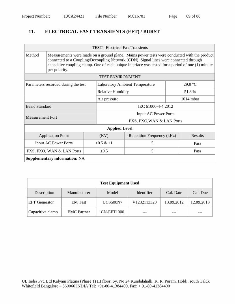
11. ELECTRICAL FAST TRANSIENTS (EFT) / BURST
TEST: Electrical Fast Transients
Method Measurements were made on a ground plane. Mains power tests were conducted with the product
connected to a Coupling/Decoupling Network (CDN). Signal lines were connected through
capacitive coupling clamp. One of each unique interface was tested for a period of one (1) minute
per polarity.
TEST ENVIRONMENT
Parameters recorded during the test Laboratory Ambient Temperature 29.8 °C
Relative Humidity 51.3 %
Air pressure 1014 mbar
Basic Standard IEC 61000-4-4:2012
Measurement Port Input AC Power Ports
FXS, FXO,WAN & LAN Ports
Applied Level
Application Point (KV) Repetition Frequency (kHz) Results
Input AC Power Ports ±0.5 & ±1 5 Pass
FXS, FXO, WAN & LAN Ports ±0.5 5 Pass
Supplementary information: NA
Test Equipment Used
Description Manufacturer Model Identifier Cal. Date Cal. Due
EFT Generator EM Test UCS500N7 V1232113320 13.09.2012 12.09.2013
Capacitive clamp EMC Partner CN-EFT1000 --- --- ---

Project Number: 13CA24421 File Number MC16781 Page 70 of 88
UL India Pvt. Ltd Kalyani Platina (Phase 1) III floor, Sy. No 24 Kundalahalli, K. R. Puram, Hobli, south Taluk
Whitefield Bangalore – 560066 INDIA Tel: +91-80-41384400, Fax: + 91-80-41384400
Figure 22: Photo of EFT test setup
EFT on A.C power line
EFT on FXS Port

Project Number: 13CA24421 File Number MC16781 Page 71 of 88
UL India Pvt. Ltd Kalyani Platina (Phase 1) III floor, Sy. No 24 Kundalahalli, K. R. Puram, Hobli, south Taluk
Whitefield Bangalore – 560066 INDIA Tel: +91-80-41384400, Fax: + 91-80-41384400
EFT on FXO Port
EFT on WAN Port

Project Number: 13CA24421 File Number MC16781 Page 72 of 88
UL India Pvt. Ltd Kalyani Platina (Phase 1) III floor, Sy. No 24 Kundalahalli, K. R. Puram, Hobli, south Taluk
Whitefield Bangalore – 560066 INDIA Tel: +91-80-41384400, Fax: + 91-80-41384400
EFT on LAN Port

Project Number: 13CA24421 File Number MC16781 Page 73 of 88
UL India Pvt. Ltd Kalyani Platina (Phase 1) III floor, Sy. No 24 Kundalahalli, K. R. Puram, Hobli, south Taluk
Whitefield Bangalore – 560066 INDIA Tel: +91-80-41384400, Fax: + 91-80-41384400
Table 18: Results for Electrical Fast Transients
Point of Application Level Polarity Observations
Power Lines
(L-N – PE- GND)
0.5kV Positive A
Negative A
1.0kV Positive A
Negative A
Signal Lines
(FXS Ports)
0.5kV Positive A
Negative A
Signal Lines
(FXO Port)
0.5kV Positive A
Negative A
Signal Lines
(WAN Port)
0.5kV Positive A
Negative A
Signal Lines
(LAN Port)
0.5kV Positive A
Negative A
Results Descriptions:
A – No noticeable changes of the operating characteristic within specified criterion A of the clause 4.1 of this
report
B – No noticeable changes of the operating characteristic within specified criterion B of the clause 4.1 of this
report.
X – Not Performed.

Project Number: 13CA24421 File Number MC16781 Page 74 of 88
UL India Pvt. Ltd Kalyani Platina (Phase 1) III floor, Sy. No 24 Kundalahalli, K. R. Puram, Hobli, south Taluk
Whitefield Bangalore – 560066 INDIA Tel: +91-80-41384400, Fax: + 91-80-41384400
12. SURGES
TEST: Surges
Method Mains power tests were conducted with the product connected to a Coupling/Decoupling
Network (CDN). The test voltage was increased from the lowest indicated level up to the
maximum level. Five (5) positive surges and five (5) negative surges were applied at each of
phases of the a.c. waveform: 0°, 90°, 180° and 270°. Each surge was applied 60 seconds after
the previous surge.
TEST ENVIRONMENT
Parameters recorded during the test Laboratory Ambient Temperature 26.4 °C
Relative Humidity 49.5 %
Air pressure 1011 mbar
Basic Standard – Mains IEC 61000-4-5: 2005
Measurement Port Input A.C. Power Ports & Signal Ports (FXS, FXO & WAN)
Applied Level
Application Point (KV) Required Surge Waveform
Input AC Power
Ports
±1.0
(Line to Line)
±2.0
(Line to Earth)
Combination Wave
(1.2µS x 50µS Voltage, 8µS x 20µS Current)
Combination Wave
(1.2µS x 50µS Voltage, 8µS x 20µS Current)
Signals Ports
FXS, FXO, WAN
±1.0
Telecom Surge Wave
10µS x 700µS
Supplementary information: NA
Test Equipment Used
Description Manufacturer Model Identifier Cal. Date Cal. Due
Surge Generator EM Test UCS500N7 V1232113320 13.09.2012 12.09.2013
Surge Generator KeyTek Thermofisher EMC Proplus 712273 03.09.2012 03.09.2013
Telecom Line CDN KeyTek CM-TLCD 612303 NA NA

Project Number: 13CA24421 File Number MC16781 Page 75 of 88
UL India Pvt. Ltd Kalyani Platina (Phase 1) III floor, Sy. No 24 Kundalahalli, K. R. Puram, Hobli, south Taluk
Whitefield Bangalore – 560066 INDIA Tel: +91-80-41384400, Fax: + 91-80-41384400
Figure 23: Photo of Surge test setup
Surge on AC power lines
Surge on FXS Ports

Project Number: 13CA24421 File Number MC16781 Page 76 of 88
UL India Pvt. Ltd Kalyani Platina (Phase 1) III floor, Sy. No 24 Kundalahalli, K. R. Puram, Hobli, south Taluk
Whitefield Bangalore – 560066 INDIA Tel: +91-80-41384400, Fax: + 91-80-41384400
Surge on FXO Port
Surge on WAN Port

Project Number: 13CA24421 File Number MC16781 Page 77 of 88
UL India Pvt. Ltd Kalyani Platina (Phase 1) III floor, Sy. No 24 Kundalahalli, K. R. Puram, Hobli, south Taluk
Whitefield Bangalore – 560066 INDIA Tel: +91-80-41384400, Fax: + 91-80-41384400
Table 19: Results for Surges on power lines
Mode of Application – Mains Level Polarity Observations
Line to Neutral
(Differential mode)
0.5kV Positive A
Negative A
1.0kV Positive A
Negative A
Line to Earth
(Common mode)
0.5kV Positive A
Negative A
1.0kV Positive A
Negative A
2.0kV Positive A
Negative A
Neutral to Earth
(Common mode)
0.5kV Positive A
Negative A
1.0kV Positive A
Negative A
2.0kV Positive A
Negative A

Project Number: 13CA24421 File Number MC16781 Page 78 of 88
UL India Pvt. Ltd Kalyani Platina (Phase 1) III floor, Sy. No 24 Kundalahalli, K. R. Puram, Hobli, south Taluk
Whitefield Bangalore – 560066 INDIA Tel: +91-80-41384400, Fax: + 91-80-41384400
Table 20: Results for Surges on Signals lines
Mode of Application – Mains Level Polarity Observations
FXS Ports
0.5kV Positive A
Negative A
1.0kV Positive A
Negative A
FXO Port
0.5kV Positive A
Negative A
1.0kV Positive A
Negative A
WAN Port
0.5kV Positive A
Negative A
1.0kV Positive A
Negative A
Results Descriptions:
A – No noticeable changes of the operating characteristic within specified criterion A of the clause 4.1 of this
report
B – No noticeable changes of the operating characteristic within specified criterion B of the clause 4.1 of this
report.
X – Not Performed.

Project Number: 13CA24421 File Number MC16781 Page 79 of 88
UL India Pvt. Ltd Kalyani Platina (Phase 1) III floor, Sy. No 24 Kundalahalli, K. R. Puram, Hobli, south Taluk
Whitefield Bangalore – 560066 INDIA Tel: +91-80-41384400, Fax: + 91-80-41384400
13. CONTINUOUS CONDUCTED DISTURBANCES (Conducted RF Susceptibility)
TEST: Radio-Frequency Continuous Conducted
Method Measurements were made on a ground plane. The EUT was located 10cm above the reference
ground plane and any associated I/O cables attached to the EUT were located between 30mm
and 50mm above the ground plane. The indicated field was pre-calibrated prior to placement
of the system under test.
TEST ENVIRONMENT
Parameters recorded during the test Laboratory Ambient Temperature 29.8 °C
Relative Humidity 49.3 %
Air pressure 1012 mbar
Basic Standard IEC 61000-4-6: 2008
Measurement Port Input AC Power Port & FXS, FXO, WAN, LAN Ports
Frequency range 150kHz to 80MHz
Applied Level
Frequency (MHz) (V rms) Modulation Results
0.150 – 80MHz 3 80% AM (1kHz) Pass
Supplementary information: Dwell time: 2.85 sec., Frequency step: 1%.
Test Equipment Used
Description Manufacturer Model Identifier Cal. Date Cal. Due
RF Signal Generator EM Test CWS500N1 V1019106601 23.08.2012 23.08.2013
CDN EM Test CDN-M2/M3 0610-09 02-01-2013 02-01-2014
EM Clamp LUTHI EM101 35917 --- ---

Project Number: 13CA24421 File Number MC16781 Page 80 of 88
UL India Pvt. Ltd Kalyani Platina (Phase 1) III floor, Sy. No 24 Kundalahalli, K. R. Puram, Hobli, south Taluk
Whitefield Bangalore – 560066 INDIA Tel: +91-80-41384400, Fax: + 91-80-41384400
Figure 24: Photo of Radio-Frequency Continuous Conducted test setup
Continuous Conducted Radio-Frequency on AC Power lines
Continuous Conducted Radio-Frequency on FXS Ports

Project Number: 13CA24421 File Number MC16781 Page 81 of 88
UL India Pvt. Ltd Kalyani Platina (Phase 1) III floor, Sy. No 24 Kundalahalli, K. R. Puram, Hobli, south Taluk
Whitefield Bangalore – 560066 INDIA Tel: +91-80-41384400, Fax: + 91-80-41384400
Continuous Conducted Radio-Frequency on FXO Port
Continuous Conducted Radio-Frequency on WAN Port

Project Number: 13CA24421 File Number MC16781 Page 82 of 88
UL India Pvt. Ltd Kalyani Platina (Phase 1) III floor, Sy. No 24 Kundalahalli, K. R. Puram, Hobli, south Taluk
Whitefield Bangalore – 560066 INDIA Tel: +91-80-41384400, Fax: + 91-80-41384400
Continuous Conducted Radio-Frequency on LAN Port
Table 21: Results for Continuous Conducted Disturbances
Point of application Observations
AC power Port A
FXS Ports A
FXO Port A
WAN Port A
LAN Port A
Results Descriptions:
A – No noticeable changes of the operating characteristic within specified criterion A of the clause 4.1 of this
report
B – No noticeable changes of the operating characteristic within specified criterion B of the clause 4.1 of this
report.
X – Not Performed.

Project Number: 13CA24421 File Number MC16781 Page 83 of 88
UL India Pvt. Ltd Kalyani Platina (Phase 1) III floor, Sy. No 24 Kundalahalli, K. R. Puram, Hobli, south Taluk
Whitefield Bangalore – 560066 INDIA Tel: +91-80-41384400, Fax: + 91-80-41384400
14. POWER-FREQUENCY MAGNETIC FIELDS
TEST: Power-frequency magnetic field
Method Measurements were made on a ground plane that extends 1-meter minimum beyond all sides
of the system under test. The indicated field was pre-calibrated prior to placement of the
system under test.
Parameters required prior to the test Laboratory Ambient Temperature 10 to 40 °C
Relative Humidity 10 to 90 %
Parameters recorded during the test Laboratory Ambient Temperature 25.5°C
Relative Humidity 55.8%
Frequency Application Point
Fully configured sample tested at the
power line frequency
50 Hz & 60 Hz Enclosure
Basic Standard IEC 61000-4-8:2009
Test Level
Frequency (Hz) A/m
50 & 60 1
Supplementary information:
Test Equipment Used
Description Manufacturer Model Identifier Cal. Date Cal. Due
Immunity Test Generator KeyTek Thermofisher EMC Proplus 712273 03.09.2012 03.09.2013
Magnetic field
immunity loop
Keytek Thermo
Electron corporation
F-1000-4-8-
9-10-L-1M 6022 NA NA

Project Number: 13CA24421 File Number MC16781 Page 84 of 88
UL India Pvt. Ltd Kalyani Platina (Phase 1) III floor, Sy. No 24 Kundalahalli, K. R. Puram, Hobli, south Taluk
Whitefield Bangalore – 560066 INDIA Tel: +91-80-41384400, Fax: + 91-80-41384400
Figure 25: Photo of Power frequency magnetic field test setup

Project Number: 13CA24421 File Number MC16781 Page 85 of 88
UL India Pvt. Ltd Kalyani Platina (Phase 1) III floor, Sy. No 24 Kundalahalli, K. R. Puram, Hobli, south Taluk
Whitefield Bangalore – 560066 INDIA Tel: +91-80-41384400, Fax: + 91-80-41384400
Table 22: Description of Product Performance
230 V- 50 Hz
Point of application Observations
X-Axis A
Y-Axis A
Z-Axis A
230 V -60 Hz
Point of application Observations
X-Axis A
Y-Axis A
Z-Axis A
Results Descriptions:
A – No noticeable changes of the operating characteristic within specified criterion A of the clause 4.1 of this
report
B – No noticeable changes of the operating characteristic within specified criterion B of the clause 4.1 of this
report.
X – Not Performed.

Project Number: 13CA24421 File Number MC16781 Page 86 of 88
UL India Pvt. Ltd Kalyani Platina (Phase 1) III floor, Sy. No 24 Kundalahalli, K. R. Puram, Hobli, south Taluk
Whitefield Bangalore – 560066 INDIA Tel: +91-80-41384400, Fax: + 91-80-41384400
15. VOLTAGE DIPS AND INTERRUPTIONS
TEST: Voltage Dips and Interruptions
Method The product was subjected to voltage dips and interruptions. Testing was performed with the
product connected directly to a generator capable of simulating the voltage drops and
interrupts as described
TEST ENVIRONMENT
Parameters recorded during the test Laboratory Ambient Temperature 29.5 °C
Relative Humidity 46.6 %
Air pressure 1013 mbar
Basic Standard IEC 61000-4-11: 2004
Measurement Port Input AC Power Ports
Applied Levels
Test level (% of UT) Duration (ms)
0% 10
40% 200
70% 500
0% 5000
Supplementary information:
Test Equipment Used
Description Manufacturer Model Identifier Cal. Date Cal. Due
Voltage Dips Generator EM Test UCS500N7 V1232113320 13.09.2012 12.09.2013

Project Number: 13CA24421 File Number MC16781 Page 87 of 88
UL India Pvt. Ltd Kalyani Platina (Phase 1) III floor, Sy. No 24 Kundalahalli, K. R. Puram, Hobli, south Taluk
Whitefield Bangalore – 560066 INDIA Tel: +91-80-41384400, Fax: + 91-80-41384400
Figure 26: Photo of voltage Dips and Short interruptions test setup:

Project Number: 13CA24421 File Number MC16781 Page 88 of 88
UL India Pvt. Ltd Kalyani Platina (Phase 1) III floor, Sy. No 24 Kundalahalli, K. R. Puram, Hobli, south Taluk
Whitefield Bangalore – 560066 INDIA Tel: +91-80-41384400, Fax: + 91-80-41384400
Table 23: Results for Voltage Dips and Interruptions
Point of application Test level (% of UT) Observations
Mains 0% A
Mains 40% A
Mains 70% A
Mains 0% C
Results Descriptions:
A – No noticeable changes of the operating characteristic within specified criterion A of the clause 4.1 of this
report
B – No noticeable changes of the operating characteristic within specified criterion B of the clause 4.1 of this
report.
X – Not Performed.