emc vplex administration guide
DESCRIPTION
EMC VPLEX Administration GuideTRANSCRIPT

EMC® VPLEX™GeoSynchrony® Release 5.1
Administration GuideP/N 300-013-919-01
EMC CorporationCorporate Headquarters:
Hopkinton, MA 01748-9103
1-508-435-1000www.EMC.com

Copyright © May, 2012 EMC Corporation. All rights reserved.
Published May 1, 2012 4:19 pm
EMC believes the information in this publication is accurate as of its publication date. The information is subject to changewithout notice.
THE INFORMATION IN THIS PUBLICATION IS PROVIDED “AS IS.” EMC CORPORATION MAKES NOREPRESENTATIONS OR WARRANTIES OF ANY KIND WITH RESPECT TO THE INFORMATION IN THIS PUBLICATION,AND SPECIFICALLY DISCLAIMS IMPLIED WARRANTIES OF MERCHANTABILITY OR FITNESS FOR A PARTICULARPURPOSE.
Use, copying, and distribution of any EMC software described in this publication requires an applicable software license.
For the most up-to-date regulatory document for your product line, go to the Technical Documentation and Advisories sectionon EMC Powerlink®.
For the most up-to-date listing of EMC product names, see EMC Corporation Trademarks on EMC.com.
All other trademarks used herein are the property of their respective owners.
EMC® VPLEX™ Administration Guide2

Contents
Preface
Chapter 1 Using the VPLEX CLILog in to/log out from the CLI............................................................................. 14CLI context tree ....................................................................................................... 15Navigate the CLI context tree ............................................................................... 17Using CLI commands............................................................................................. 21
Chapter 2 CLI Workspace and User AccountsConfigure the CLI workspace ............................................................................... 30Manage user accounts ............................................................................................ 32
Chapter 3 Meta-volumesAbout meta-volumes.............................................................................................. 38Create a meta-volume ............................................................................................ 40Back up the meta-volume...................................................................................... 42Move a meta-volume.............................................................................................. 46Rename a meta-volume ......................................................................................... 47Delete a meta-volume ............................................................................................ 48Display meta-volume ............................................................................................. 49
Chapter 4 System ManagementSPS battery conditioning........................................................................................ 54Call-home notifications and system reporting ................................................... 57Event log locations.................................................................................................. 60Compare and Write (hardware acceleration) ..................................................... 61
Chapter 5 Distributed devicesAdditional documentation .................................................................................... 66Logging volumes .................................................................................................... 67Rule-sets ................................................................................................................... 70Configure distributed devices............................................................................... 79Create a virtual volume on a distributed device................................................ 85Expose a virtual volume to hosts.......................................................................... 87Expose a virtual volume to a remote host........................................................... 89Add a local mirror to distributed device............................................................. 90
EMC® VPLEX™ Administration Guide 3
Remove a local mirror from a distributed device.............................................. 92Create a distributed device from an exported volume..................................... 93Display/enable/disable automatic device rebuilds ......................................... 94Configure I/O resumption after a network outage .......................................... 96
Chapter 6 Data migrationAbout data migrations......................................................................................... 100About rebuilds ...................................................................................................... 102One-time data migrations ................................................................................... 104Batch migrations................................................................................................... 109
Chapter 7 Configure the NetworkCLI contexts........................................................................................................... 119Modify the network configuration .................................................................... 123
Chapter 8 Consistency groupsAbout VPLEX consistency groups..................................................................... 130Properties of consistency groups ....................................................................... 137Manage consistency groups................................................................................ 146Operate a consistency group .............................................................................. 166
Chapter 9 VPLEX WitnessIntroduction .......................................................................................................... 172Failures in Metro systems without/with VPLEX Witness............................. 175Failures in Geo systems without/with VPLEX Witness ................................ 178Install, enable, and manage VPLEX Witness ................................................... 183VPLEX Witness operation................................................................................... 185
Chapter 10 Cache vaultsAbout cache vaulting........................................................................................... 198The vaulting process ............................................................................................ 201Recovery after vault ............................................................................................. 203
Chapter 11 RecoverPointIntroduction .......................................................................................................... 208RecoverPoint CLI context.................................................................................... 221Configuration/operation guidelines for VPLEX Metro and RP ................... 223Management tools................................................................................................ 230
Chapter 12 Performance and monitoringAbout performance .............................................................................................. 232About performance monitoring ......................................................................... 234Monitor performance using the CLI.................................................................. 237Pre-configured performance monitors.............................................................. 246Statistics ................................................................................................................. 251
Glossary
EMC® VPLEX™ Administration Guide4
Index
EMC® VPLEX™ Administration Guide 5

EMC® VPLEX™ Administration Guide6

Title Page
Tables
1 VPLEX user roles, default passwords, and privileges..................................................... 321 meta-volume display fields ................................................................................................. 492 event severity and call-home notifications........................................................................ 573 VPLEX log file locations....................................................................................................... 604 Default rule-sets .................................................................................................................... 715 Migration status................................................................................................................... 1056 Batch migration summary ................................................................................................. 1137 Consistency groups detach-rules, visibility, storage-at-volumes, and cache-mode . 1548 Display consistency group field descriptions ................................................................. 1619 VPLEX Witness display fields ........................................................................................... 18510 Parameters impacting RPO in Geo configurations ........................................................ 23311 Maximum roll back loss for Geo with 16 asynchronous consistency groups ............ 23312 Monitor and sink field descriptions ................................................................................. 24313 Back-end fibre channel port (be-prt) statistics ................................................................ 25314 Cache statistics..................................................................................................................... 25315 Director statistics ................................................................................................................. 25316 Directory statistics............................................................................................................... 25517 Front-end director (fe-director) statistics......................................................................... 25518 Front-end volume (fe-lu) statistics.................................................................................... 25619 Front-end port (fe-prt) statistics ........................................................................................ 25620 Remote RAID (ramf) statistics........................................................................................... 25721 Remote data memory access (rdma) statistics ................................................................ 25722 Storage-volume statistics ................................................................................................... 25823 Virtual-volume statistics .................................................................................................... 25824 Write pacing (wrt-pacing) statistics.................................................................................. 25825 Consistency-group (cg) statistics ...................................................................................... 25926 RecoverPoint volume statistics (rp-spl-vol) .................................................................... 26027 RecoverPoint splitter statistics (rp-spl-node) .................................................................. 26028 IP WAN COM (ip-com-port) statistics............................................................................. 26129 Fibre Channel WAN COM (fc-com-port) statistics ........................................................ 26230 SNMP director level statistics............................................................................................ 26231 SNMP port level statistics .................................................................................................. 263
EMC® VPLEX™ Administration Guide 7

EMC® VPLEX™ Administration Guide8

Preface
As part of an effort to improve and enhance the performance and capabilities of its productline, EMC from time to time releases revisions of its hardware and software. Therefore, somefunctions described in this document may not be supported by all revisions of the software orhardware currently in use. Your product release notes provide the most up-to-date informationon product features.
If a product does not function properly or does not function as described in this document,please contact your EMC representative.
About this guide This guide is part of the VPLEX documentation set, and is intended for use bycustomers and service providers to configure and manage a storage environment.
Relateddocumentation
Related documents (available on EMC Powerlink) include:
◆ EMC VPLEX Release 5.0 Release Notes
◆ EMC VPLEX Release 5.1 Release Notes
◆ EMC VPLEX Product Guide
◆ EMC VPLEX Site Preparation Guide
◆ EMC VPLEX Configuration Worksheet
◆ EMC VPLEX Configuration Guide
◆ EMC VPLEX CLI Guide
◆ EMC VPLEX Hardware Installation Guide
◆ VPLEX Management Console Help
◆ EMC VPLEX Security Configuration Guide
◆ EMC VPLEX Open-Source Licenses
◆ EMC Regulatory Statement for EMC VPLEX
◆ EMC VPLEX Procedure Generator
◆ EMC Host Connectivity Guides
Conventions used inthis document
EMC uses the following conventions for special notices.
Note: A note presents information that is important, but not hazard-related.
A caution contains information essential to avoid data loss or damage to the systemor equipment.
EMC® VPLEX™ Administration Guide 9
Preface
IMPORTANT
An important notice contains information essential to operation of the software.
Typographical conventions
EMC uses the following type style conventions in this document:
Where to get help EMC support, product, and licensing information can be obtained as follows.
Product information — For documentation, release notes, software updates, or forinformation about EMC products, licensing, and service, go to the EMC Powerlinkwebsite (registration required) at:
http://Powerlink.EMC.com
Technical support — For technical support, go to EMC Customer Service onPowerlink. To open a service request through Powerlink, you must have a validsupport agreement. Please contact your EMC sales representative for details aboutobtaining a valid support agreement or to answer any questions about your account.
Normal Used in running (nonprocedural) text for:• Names of interface elements (such as names of windows, dialog boxes, buttons,
fields, and menus)• Names of resources, attributes, pools, Boolean expressions, buttons, DQL
statements, keywords, clauses, environment variables, functions, utilities• URLs, pathnames, filenames, directory names, computer names, filenames, links,
groups, service keys, file systems, notifications
Bold Used in running (nonprocedural) text for:• Names of commands, daemons, options, programs, processes, services,
applications, utilities, kernels, notifications, system call, man pages
Used in procedures for:• Names of interface elements (such as names of windows, dialog boxes, buttons,
fields, and menus)• What user specifically selects, clicks, presses, or types
Italic Used in all text (including procedures) for:• Full titles of publications referenced in text• Emphasis (for example a new term)• Variables
Courier Used for:• System output, such as an error message or script• URLs, complete paths, filenames, prompts, and syntax when shown outside of
running text
Courier bold Used for:• Specific user input (such as commands)
Courier italic Used in procedures for:• Variables on command line• User input variables
< > Angle brackets enclose parameter or variable values supplied by the user
[ ] Square brackets enclose optional values
| Vertical bar indicates alternate selections - the bar means “or”
{ } Braces indicate content that you must specify (that is, x or y or z)
... Ellipses indicate nonessential information omitted from the example
EMC® VPLEX™ Administration Guide10
Preface
Your comments Your suggestions will help us continue to improve the accuracy, organization, andoverall quality of the user publications. Please send your opinion of this document to:
EMC® VPLEX™ Administration Guide 11

Preface
EMC® VPLEX™ Administration Guide12

1
This chapter describes how to use the VPLEX™ command line interface (CLI).
◆ Log in to/log out from the CLI ........................................................ 14◆ CLI context tree................................................................................... 15◆ Navigate the CLI context tree........................................................... 17
◆ Using CLI commands ........................................................................ 21◆ Tab completion ................................................................................... 22◆ Wildcards ............................................................................................ 23◆ Names .................................................................................................. 24◆ Command globbing ........................................................................... 24◆ --verbose and --help arguments ....................................................... 25◆ Get help................................................................................................ 26
Using the VPLEX CLI
EMC VPLEX CLI Guide 13

Using the VPLEX CLI
Log in to/log out from the CLI
Log in 1. Log in to the service account at the cluster's management server's public IPaddress using an SSH client (PuTTY or OpenSSH). Configure the SSH client asfollows:
• Port 22
• SSH protocol version is set to 2
• Scrollback lines set to 20000
The log in prompt appears:
login as:
2. Type service and press ENTER. A password prompt appears:
Using keyboard-interactive authentication.Password:
3. Type the service password and press ENTER. The default password isMi@Dim7T. A server prompt appears:
service@ManagementServer:~>
4. Type the vplexcli command to connect to the VPlexcli:
service@ManagementServer:~> vplexcli
Several messages are displayed, and a username prompt appears:
Trying 127.0.0.1...Connected to localhost.Escape character is '^]'.
Enter User Name:
5. Type service and press ENTER.
Enter User Name: service
A password prompt appears:
Password:
6. Type the service password and press ENTER. The default password isMi@Dim7T.
The VPlexcli prompt appears:
creating logfile:/var/log/VPlex/cli/session.log_service_localhost_T28921_20101020175912
VPlexcli:/>
Log out Use the exit command to exit the VPlexcli from any context.
For example:
VPlexcli:/clusters> exitConnection closed by foreign host.
EMC VPLEX CLI Guide14
Using the VPLEX CLI
CLI context treeThe CLI is divided into command contexts. Some commands are accessible from allcontexts, and are referred to as ‘global commands’.
The remaining commands are arranged in a hierarchical context tree. Thesecommands can only be executed from the appropriate location in the context tree.
Understanding the command context tree is critical to using the VPlexcli effectively.
The root context contains eight sub-contexts:
◆ clusters/ - Create and manage links between clusters, devices, extents, systemvolumes and virtual volumes. Register initiator ports, export target ports, andstorage views.
◆ data-migrations/ - Create, verify, start, pause, cancel, and resume datamigrations of extents or devices.
◆ distributed-storage/ - Create and manage distributed devices and rule sets.
◆ engines/ - Configure and manage directors, fans, management modules, andpower.
◆ management-server/ - Manage the Ethernet ports.
◆ monitoring/ - Create and manage performance monitors.
◆ notifications/ - Create and manage call-home events.
◆ system-defaults/ - Display systems default settings.
Except for system-defaults/, each of the eight sub-contexts contains one or moresub-contexts to configure, manage, and display sub-components.
Command contexts have commands that can be executed only from that context. Thecommand contexts are arranged in a hierarchical context tree. The topmost context isthe root context, or “/”.
EMC VPLEX CLI Guide 15

Using the VPLEX CLI
EMC VPLEX CLI Guide16

Using the VPLEX CLI
Navigate the CLI context treeUse the cd command to navigate between command contexts.
The current context is always displayed at the VPlexcli prompt:
VPlexcli:/> cd /clusters/cluster-1/devices/
VPlexcli:/clusters/cluster-1/devices>
For example, to navigate from the root (/) context to the monitoring context for aspecified director:
VPlexcli:/> cd /monitoringVPlexcli:/monitoring> cd /directors/VPlexcli:/monitoring/directors> cd /director-1-1-BVPlexcli:/monitoring/directors/director-1-1-B> cd /monitorsVPlexcli:/monitoring/directors/director-1-1-B/monitors> cd/director-1-1-BVPlexcli:/monitoring/directors/director-1-1-B/monitors/director-1-1-B> lsAttributes:Name Value--------------- ---------------------------------average-period 1sbucket-count 64...Alternatively, type all the context identifiers in a single command. For example, theabove navigation can be typed as:
VPlexcli:/> cd/monitoring/directors/director-1-1-B/monitors/director-1-1-B_director
VPlexcli:/monitoring/directors/director-1-1-B/monitors/director-1-1-B>
Use the cd command with no arguments or followed by three periods (cd... ) to returnto the root context:
VPlexcli:/engines/engine-1-1/fans> cd
VPlexcli:/>
Use the cd command followed by two periods (cd..) to return to the contextimmediately above the current context:
VPlexcli:/monitoring/directors/director-1-1-B> cd ..
VPlexcli:/monitoring/directors>
To navigate directly to a context from any other context use the cd command andspecify the absolute context path. In the following example, the cd command changesthe context from the data migrations/ extent-migrations context to theengines/engine-1/fans context:
VPlexcli:/data-migrations/extent-migrations> cd/engines/engine-1-1/fans/
VPlexcli:/engines/engine-1-1/fans>
pushd and popd commands◆ Use the pushd directory command to save the current directory, and jump to the
specified directory.
EMC VPLEX CLI Guide 17

Using the VPLEX CLI
Once a directory is added to the pushd stack, use the pushd command with noargument to switch back to the previous directory.
In the following example, pushd toggles between the engines and monitoringparent contexts:
VPlexcli:/engines/engine-1-1/directors/director-1-1-A> pushd/monitoring/directors/director-1-1-A[/monitoring/directors/director-1-1-A,/engines/engine-1-1/directors/director-1-1-A,/monitoring/directors/director-1-1-A]
VPlexcli:/monitoring/directors/director-1-1-A> pushd[/engines/engine-1-1/directors/director-1-1-A,/monitoring/directors/director-1-1-A,/monitoring/directors/director-1-1-A]
VPlexcli:/engines/engine-1-1/directors/director-1-1-A> pushd[/monitoring/directors/director-1-1-A,/engines/engine-1-1/directors/director-1-1-A,/monitoring/directors/director-1-1-A]
VPlexcli:/monitoring/directors/director-1-1-A>
◆ Use the dirs command to display to the current context stack:
VPlexcli:/clusters/cluster-1> dirs[/clusters/cluster-1, /, /,/engines/engine-1-1/directors/director-1-1-A/hardware/ports/A5-GE01, /]
◆ Use the popd command to remove the last directory saved by the pushdcommand and jump to the new top directory.
In the following example, the dirs command displays the context stack saved bythe pushd command, and the popd command removes the top directory, andjumps to the new top directory:
VPlexcli:/engines/engine-1-1/directors/director-1-1-A> dirs[/engines/engine-1-1/directors/director-1-1-A,/monitoring/directors/director-1-1-A]
VPlexcli:/engines/engine-1-1/directors/director-1-1-A> popd[/engines/engine-1-1/directors/director-1-1-A]
VPlexcli:/monitoring/directors/director-1-1-A>
Note: The context tree displays only those objects associated with directors to which themanagement system is connected.
◆
VPlexcli:/> cd /monitoring/directors/director-1-1-B/monitors/
VPlexcli:/monitoring/directors/director-1-1-B/monitors>
◆ The ls command displays the sub-contexts immediately accessible from thecurrent context:
VPlexcli:/> lsclusters data-migrations distributed-storageengines management-server monitoring
EMC VPLEX CLI Guide18

Using the VPLEX CLI
notifications system-defaults
◆ The ls -l command displays more information about the current sub-contexts:
VPlexcli:/data-migrations> ls -lName Description----------------- -------------------------------------device-migrations Contains all the device migrations in the system.extent-migrations Contains all the extent migrations in the system.
◆ For contexts where the next lowest level is a list of individual objects, the lscommand displays a list of the objects:
VPlexcli:/clusters/cluster-1/exports/ports> lsP000000003B2017DF-A0-FC00 P000000003B2017DF-A0-FC01P000000003B2017DF-A0-FC02 P000000003B2017DF-A0-FC03P000000003B3017DF-B0-FC00 P000000003B3017DF-B0-FC01P000000003B3017DF-B0-FC02 P000000003B3017DF-B0-FC03
◆ <Tab>
For example, type cd and press <Tab> in the data-migrations context to displayavailable options:
VPlexcli:/data-migrations> cd <Tab>
device-migrations/ extent-migrations/
◆ The tree command displays the immediate sub-contexts in the tree using thecurrent context as the root:
VPlexcli:/ cd /clusters/cluster-1/devices/Symm_rC_3
VPlexcli:/clusters/cluster-1/devices/Symm_rC_3> tree/clusters/cluster-1/devices/Symm_rC_3:
componentsSymm_rC_3_extent_0Symm_rC_3_extent_1
◆ The tree -e command displays immediate sub-contexts in the tree and anysub-contexts under them:
VPlexcli:/clusters/cluster-1/devices/Symm_rC_3> tree -e/clusters/cluster-1/devices/Symm_rC_3:
componentsSymm_rC_3_extent_0
componentsSymm0487_44C
componentsSymm_rC_3_extent_1
componentsSymm0487_44B
components
Note:
VPlexcli:/clusters/cluster-1> tree/clusters/cluster-1:
cluster-connectivitycluster-links
to-cluster-2proxy-serversstatic-routes
devicesbase0
componentsextent_CX4_lun0_1
EMC VPLEX CLI Guide 19

Using the VPLEX CLI
componentsCX4_lun0
components...exports
initiator-portsLicoJ006_hba0LicoJ006_hba1
.
.
.ports
P000000003CA00147-A0-FC00P000000003CA00147-A0-FC01
storage-viewsLicoJ009LicoJ013
storage-elementsextents
extent_CX4_Logging_1
EMC VPLEX CLI Guide20
Using the VPLEX CLI
Using CLI commandsThis section describes the following topics:
◆ Display currently available commands .......................................... 21◆ Page output ......................................................................................... 22◆ Tab completion ................................................................................... 22◆ Wildcards ............................................................................................ 23◆ Command globbing ........................................................................... 24◆ Positional command arguments ...................................................... 25◆ --verbose and --help arguments ....................................................... 25◆ Search command history................................................................... 26◆ View command history ..................................................................... 26◆ Get help................................................................................................ 26
Display currently available commandsThe commands that make up the CLI fall into two groups:
◆ Global commands that can be used in any context. For example: cd, date, ls, exit,user, and security.
◆ Context-specific commands that can be used only in specific contexts. Forexample, to use the copy command, the context must be/distributed-storage/rule-sets.
Use the help command to display a list of all commands (including the globalcommands) available from the current context.
Use the help -G command to display a list of available commands in the currentcontext excluding the global commands:
VPlexcli:/notifications> help -GCommands specific to this context and below:call-home snmp-trap
Some contexts “inherit” commands from their parent context. These commands canbe used in both the current context and the context immediately above in the tree:
VPlexcli:/distributed-storage/bindings> help -GCommands inherited from parent contexts:dd rule rule-set summary
Some commands are loosely grouped by function. For example, the commands tocreate and manage performance monitors start with the word “monitor”.
Use the <Tab> key display the commands within a command group. For example, todisplay the commands that start with the word “monitor”, type “monitor” followedby the <Tab> key:
VPlexcli:/> monitor <Tab>
add-console-sink add-file-sink collect createdestroy remove-sinkstat-list
EMC VPLEX CLI Guide 21

Using the VPLEX CLI
Page outputFor large configurations, output from some commands can reach hundreds of lines.
Paging displays long output generated by the ll and ls commands one “page” at atime:
To enable paging, add -p at the end of any command:
VPlexcli:/clusters/cluster-1/storage-elements> ls storage-volumes -p
One page of output is displayed. The following message is at the bottom of the firstpage:
-- more --(TOP )- [h]elp
Press the spacebar to display the next page.
The message now indicates what percentage of the output has been displayed:
-- more --( 24%)- [h]elp
h - Displays instructions on how to move and search the output.
q - Exits paging mode.
Tab completion Use the <Tab> key to:
◆ Complete a command
◆ Display valid contexts and commands
◆ Display command arguments
Complete acommand
Use the <Tab> key to automatically complete a path or command until thepath/command is no longer unique.
For example, to navigate to the UPS context on a single cluster (named cluster-1),type:
cd /clusters/cluster-1/uninterruptible-power-supplies/
To type the same command using tab completion:
1. Type cd c <Tab>
Since 'clusters’ is the only context starting with ‘c’ at the root level, the CLIauto-completes the selection:
cd /clusters/
2. There is only one cluster (it is unique). Press <Tab> to automatically specify thecluster:
cd /clusters/cluster-1/
3. Type a u to select the uninterruptible-power-supplies context and press <Tab>.
The u is unique at the current context, and the CLI auto-completes the selection:
cd /clusters/cluster-1/uninterruptible-power-supplies/
Display valid contextsand commands
Press <Tab> after typing a partial context path to display a list of valid commandsand/or contexts for the current context:
VPlexcli:/> cd /clusters/cluster-1/ <Tab>
EMC VPLEX CLI Guide22
Using the VPLEX CLI
cluster-connectivity/ devices/exports/ storage-elements/system-volumes/ uninterruptible-power-supplies/virtual-volumes/
VPlexcli:/> cd /clusters/cluster-1/
Display commandarguments
Press <Tab> after typing a command name to display the command’s arguments. Forexample:
VPlexcli:/> monitor <Tab>
add-console-sink add-file-sink collectcreate destroy remove-sink stat-list
Wildcards The VPlexcli includes 3 wildcards:• * - matches any number of characters.
• ? - matches any single character.
• [a|b|c] - matches any of the single characters a or b or c.
* wildcard Use the * wildcard to apply a single command to multiple objects of the same type(directors or ports). For example, to display the status of ports on each director in acluster, without using wildcards:
ll engines/engine-1-1/directors/director-1-1-A/hardware/portsll engines/engine-1-1/directors/director-1-1-B/hardware/portsll engines/engine-1-2/directors/director-1-2-A/hardware/portsll engines/engine-1-2/directors/director-1-2-B/hardware/ports...
Alternatively:◆ Use one * wildcard to specify all engines, and
◆ Use a second * wildcard specify all directors:
ll engines/engine-1-*/directors/*/hardware/ports
** wildcard Use the ** wildcard to match all contexts and entities between two specified objects.For example, to display all director ports associated with all engines without usingwildcards:
ll /engines/engine-1-1/directors/director-1-1-A/hardware/portsll /engines/engine-1-1/directors/director-1-1-B/hardware/ports...Alternatively, use a ** wildcard to specify all contexts and entities between /enginesand ports:
ll /engines/**/ports
? wildcard Use the ? wildcard to match a single character (number or letter).
ls /storage-elements/extents/0x1?[8|9]
Returns information on multiple extents.
[a|b|c] wildcard Use the [a|b|c] wildcard to match one or more characters in the brackets.
EMC VPLEX CLI Guide 23
Using the VPLEX CLI
ll engines/engine-1-1/directors/director-1-1-A/hardware/ports/A[0-1]
displays only ports with names starting with an A, and a second character of 0 or 1.
Names Major components of the VPLEX are named as follows:
◆ Clusters - VPLEX Local™ configurations have a single cluster, with a cluster ID of1. VPLEX Metro™ and VPLEX Geo™ configurations have two clusters withcluster IDs of 1 and 2.
VPlexcli:/clusters/cluster-1/
◆ Engines are named <engine-n-n> where the first value is the cluster ID (1 or 2) andthe second value is the engine ID (1-4).
VPlexcli:/engines/engine-1-2/
◆ Directors are named <director-n-n-n> where the first value is the cluster ID (1 or2), the second value is the engine ID (1-4), and the third is A or B.
VPlexcli:/engines/engine-1-1/directors/director-1-1-A
For objects that can have user-defined names, names must comply with the followingrules:
◆ Can contain uppercase and lowercase letters, numbers, and underscores
◆ No spaces
◆ Cannot start with a number
◆ No more than 63 characters
Command globbingCommand “globbing” combines wildcards and context identifies in a singlecommand. Globbing can address multiple entities using a single command.
Example 1 In the following example, a single command enables ports in all engines and alldirectors (A and B) whose name include 0-FC and 1-FC:
set /engines/*/directors/*/hardware/ports/*[0-1]-FC*:: enabled true
◆ First * wildcard — All engines in the cluster.
◆ Second * wildcard — All directors in the cluster.
◆ Third * wildcard — All A-side ports and all B-side ports.
◆ The [0-1] limits the selections to all port numbers that start with A0, A1, B0, or B1.
◆ Fourth * wildcard — All ports whose numbers start with A0-FC, A1-FC, B0-FC, orB1-FC.
Example 2 To display the status of all the director ports on a large configuration using nowildcards, type:
ll /engines/engine-1-<Enclosure_ID>/directors/<director_name>/hardware/ports
for each engine and director.
Using the * wildcard reduces this task to a single command:
ll /engines/engine-1-*/directors/*/hardware/ports
EMC VPLEX CLI Guide24

Using the VPLEX CLI
Using the ** wildcard simplifies the command even more:
ll /**/ports
Positional command argumentsMost commands require arguments.
Some command arguments are positional. That is, the argument can be typed withoutan identifier IF it is entered in the position specified by the command syntax.
For example, the alias command has two arguments in the following order (syntax):
alias [-n|--name] <alias name> [-t|to] <“string of commands in quotes”>
Type the command with the arguments with identifiers in any order (not as specifiedby the syntax):
VPlexcli:/> alias --to "cd clusters" --name cdcor,
Type the command with the arguments without identifiers in the order specified by thecommand syntax:
VPlexcli:/> alias cdc "cd clusters"
--verbose and --help argumentsAll commands have two arguments:
◆ --help displays the online help for the specified command. For example:
VPlexcli:/> exec --helpsynopsis: exec [<options>] <command name> <word>*
Executes an external program.
options (* = required):...
See “Get help” on page 26.
◆ --verbose displays additional information for some commands. For example,without --verbose argument:
VPlexcli:/> connectivity validate-be
Summary
Cluster cluster-1This cluster has 0 storage-volumes which do not have dual pathsThis cluster has 0 storage-volumes which are not visible from all directors
With --verbose argument:
VPlexcli:/> connectivity validate-be --verboseStorage volumes that are dead or unreachable:
Cluster Dead or Unreachable Storage Volumes--------- ----------------------------------------
EMC VPLEX CLI Guide 25

Using the VPLEX CLI
cluster-2 VPD83T3:60004530000000080007f16e9512a2b1cluster-1 VPD83T3:60004530000000010007f16e9512a2a5
VPD83T3:60004530000000010007f16e9512a2a7VPD83T3:60004530000000010007f16e9512a2a9
SummaryCluster cluster-2
This cluster has 1 storage-volumes which are dead or unreachableThis cluster has 0 storage-volumes which do not have dual pathsThis cluster has 0 storage-volumes which are not visible from all directors
Cluster cluster-1This cluster has 3 storage-volumes which are dead or unreachableThis cluster has 0 storage-volumes which do not have dual pathsThis cluster has 0 storage-volumes which are not visible from all directors
Search command history◆ To display the last commands typed, press the up arrow key.
◆ To search for a command typed in the current CLI session, press Ctrl-r.
The reverse search prompt is displayed:
(reverse-i-search)'':
Type the first letter of the command to search for. After the first letter is typed, thesearch tool displays a list of possible matches.
View command historyUse the “up arrow” key to display the last command typed.
Use the “up arrow” key, multiple times to display recent command history.
Use the history command to display a complete list of commands executed in thecurrent session:
VPlexcli:/engines/engine-0-0/directors> historyVPlexcli:/> history0 cd engines/engine-0-0/directors1 extent unclaim *2 ls3 ls -l4 extent claim *5 ls6 ls -l7 ls -la
Use the history nn command to display the last nn entries in the list:
VPlexcli:/clusters/cluster-1> history 22478 ls storage-volumes -p479 cd clusters/cluster-1/480 ls storage-volumes481 cd storage-elements/482 ls storage-volumes -p
Get help ◆ Use the help or ? command with no arguments to display all the commandsavailable, the current context, including global commands.
◆ Use the help or ? command with -G argument to display all the commandsavailable, the current context, excluding global commands:
EMC VPLEX CLI Guide26
Using the VPLEX CLI
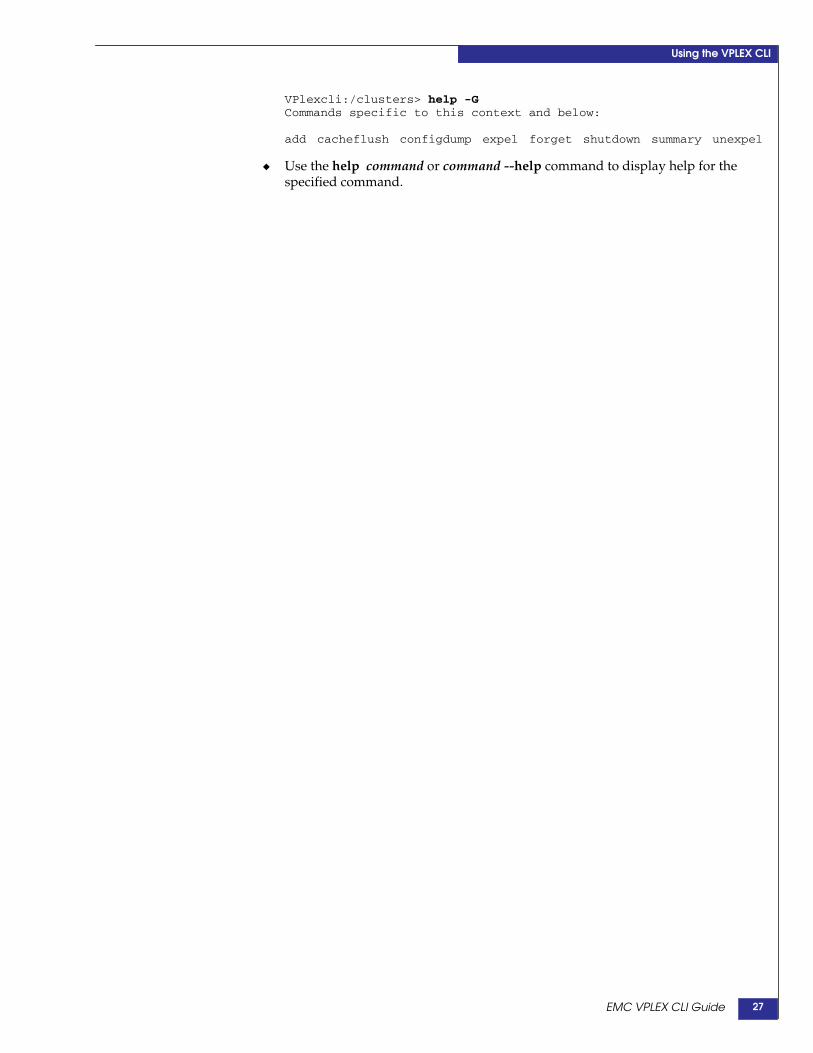
VPlexcli:/clusters> help -GCommands specific to this context and below:
add cacheflush configdump expel forget shutdown summary unexpel
◆ Use the help command or command --help command to display help for thespecified command.
EMC VPLEX CLI Guide 27

Using the VPLEX CLI
EMC VPLEX CLI Guide28
2
This chapter describes how to use the VPLEX command line interface (CLI) toconfigure the CLI workspace and to manage user accounts.
◆ Configure the CLI workspace......................................................... 30◆ Set/remove the login banner............................................................ 30◆ Set the threshold for console logging .............................................. 30◆ Set window width to 100................................................................... 31
◆ Manage user accounts....................................................................... 32◆ Add a user account ............................................................................ 32◆ First login to a new user account ..................................................... 33◆ Delete a user account. ........................................................................ 33◆ Change user account password ....................................................... 34◆ Reset a user account........................................................................... 34
CLI Workspace and UserAccounts
EMC® VPLEX™ Administration Guide 29

CLI Workspace and User Accounts
Configure the CLI workspaceThe workspace is the appearance and behavior of a CLI session. Use the proceduresdescribed in this section to control the output of commands, the level of loggingmessages sent to the console, and to search the command history of the current CLIsession.
Set/remove thelogin banner
You can customize the login banner for the VPLEX management servers.
Use the security set-login-banner command to apply the contents of a text file as thelogin banner.
The change takes effect at the next login to the management server.
The formatting of the text in the specified text file is replicated in the banner.
There is no limit to the number of characters or lines in the specified text file.
The text file must be saved in a directory on the management server.
In the following example, a text file “login-banner.txt” containing the following linesis specified as the login banner:
VPLEX cluster-1/Hopkinton
Test lab 3, Room 6, Rack 47
Metro with RecoverPoint CDP
VPlexcli:/> security set-login-banner -b/home/service/login-banner.txt
The text provided in the specified file will be set as the Login bannerfor this management server.
Any previously applied banner will be overwritten.Do you want to proceed ? (Yes/No) Yes
At next login to the management server, the new login banner is displayed:
login as: serviceVPLEX cluster-1/HopkintonTest lab 3, Room 6, Rack 47Metro with RecoverPoint CDPPassword:
Use the security remove-login-banner command to remove the login banner.
VPlexcli:/> security remove-login-banner
The login banner of this management server will be removed.Do you want to proceed ? (Yes/No) yes
Set the threshold for console loggingThe console logger displays messages received from directors on the console.
By default, the console displays only emergency (level 0) messages.
Messages are categorized into 8 severities (0-7), with 0 being the most severe:
7 - debug (debug-level messages)
6 - info (informational messages)
5 - notice (normal but significant messages)
EMC® VPLEX™ Administration Guide30

CLI Workspace and User Accounts
4 - warning (warning messages)
3 - err (error messages)
2 - crit (critical messages)
1 - alert (messages that must be handled immediately)
0 - emerg (messages notifying the system as unusable)
To enable messages with lower severity to appear on the console, change thethreshold of the logging filter for the console.
1. Use the log filter list command to display existing log filters.
VPlexcli:/> log filter list1. [Threshold='>0'] Destination='null' Consume='true'2. [Message matches 'Family and Fru Id Mismatch Retrieved']Destination='null' Consume='true'
2. Determine the ID of the filter controlling the display of messages to the console.The console filter has the following attributes:
Threhold=’>=0’Destination= ‘null’Consume=’true’
3. Use the log filter destroy command to delete the existing console logging filter.
VPlexcli:> log filter destroy 1
4. Use the log filter create command to create a new filter for the console with therequired threshold:
VPlexcli:> log filter create --threshold <n> --component “logserver”
where n is 0-7.
Note: The threshold value filters all messages with greater or equal severity.To see critical (2) and above (0 and 1), set the threshold at 3.To see error (3) and above (0, 1, and 2) set the threshold at 4.
Set window width to 100Output from many commands is more than 80 columns wide. EMC recommends thatthe command window in which VPlexcli is running be expanded to at least 100columns in width.
EMC® VPLEX™ Administration Guide 31

CLI Workspace and User Accounts
Manage user accountsVPLEX comes with two preconfigured user accounts that cannot be removed: serviceand admin. Admin users can add, modify, and delete additional user accounts.
Table 1 lists the role, privileges and default password for each level of user account.
All users can display user account names and change the password for their ownaccount.
Note: Administrative privileges are required to add, delete, and reset user accounts. Thepassword for the admin account must be reset the first time the admin account is accessed.After the admin password has been reset, the admin user can manage (add, delete, reset) useraccounts.
To change the password for the admin account, ssh to the management server as user “admin”.Enter the default password teS6nAX2. A prompt to change the admin account passwordappears. Enter a new password.
Add a user account1. Log in to the admin account of the VPLEX CLI.
2. Type the user add <username> command.
Usernames may be up to 1-32 characters, and contain numbers, letters and specialcharacters, and no spaces. For example:
VPlexcli:/> user add TestUser
A prompt for the Administrator password appears:
admin password:
3. Type the password for the Administrator username.
Table 1 VPLEX user roles, default passwords, and privileges
Component RoleDefaultaccount
Defaultpassword Privileges
Managementserver
Service service Mi@Dim7T • Access to the management server desktop, CLI, andManagement Console GUI
• Ability to start and stop management server services• Access to most files on the file system
Administrator admin teS6nAX2 • Ability to create, modify, and delete VPLEX user accounts• Access to management server desktop, CLI, and GUI• Ability to start and stop management server services
Fibre ChannelCOM switches
Service service Mi@Dim7T • Access to the switch interface• Ability to start and stop switch services• Access to most files on the switch
Administrator admin Ry3fog4M • Access to the switch interface• Ability to add and delete other accounts• Ability to change passwords
User user jYw13ABn • Access to the switch interface
EMC® VPLEX™ Administration Guide32

CLI Workspace and User Accounts
A prompt for the new password for the username being added appears:
New password:
4. Type the password for the new username. Passwords must be at least eightcharacters, and may contain numbers, letters, and special characters. No spaces.No dictionary words.
A prompt to confirm the new password appears:
Confirm password:
5. Retype the password.
6. Repeat steps 2-5 for each new user account.
7. Use the user list command to verify the new account(s):
VPlexcli:/> user listUsername--------adminmonitoruserserviceTestUser
First login to a new user accountIn order to login to the CLI, newly created user accounts must change their passwordon the management server.
The new password must be at least 14 characters long.
Example of a first login after an account is created:
login as: newuserUsing keyboard-interactive authentication.Password: old-passwordUsing keyboard-interactive authentication.Password change requested. Choose a new password.Old Password: old-passwordUsing keyboard-interactive authentication.New Password: my-new-passwordUsing keyboard-interactive authentication.Reenter New Password: my-new-passwordPassword changed.
localuser@ManagementServer:~>
After this initial login is completed, subsequent logins behave as described in “Login” on page 14
Delete a user account.1. Log in to the VPLEX CLI as an Administrator user.
2. Use the user list command to display all accounts:
VPlexcli:/> user listUsername--------adminmonitoruserserviceTestUser
EMC® VPLEX™ Administration Guide 33

CLI Workspace and User Accounts
3. Type the user remove <username> command:
VPlexcli:/> user remeove TestUser
A prompt for the Administrator password appears:
admin password:
4. Type the password for the Administrator username.
The specified user username is removed.
5. Use the user list command to verify the deletion.
Change user account passwordAllows all users to change the password only for their own username.
1. Login to the CLI using the account whose password needs to be changed.
2. Use the user passwd <username> command to change the password of anexisting user.
For example:
VPlexcli:/> user passwd monitoruser
A prompt for the current password appears:
old password:
A prompt for the new password appears:
New password:
3. Type the new password. Passwords must be at least 14 characters long, and mustnot be dictionary words.
A prompt to confirm the new password appears:
Confirm password:
4. Retype the password.
Reset a user account1. Login as an Administrator user.
2. Type the user reset --username <username> command:
VPlexcli:/> user reset --username TestUser
A prompt for the Administrator password appears:
admin password:
3. Type the password for the Administrator username.
A prompt for new password for the username being reset appears:
New password:
4. Type a new password for the username.
A prompt to confirm the new password appears:
EMC® VPLEX™ Administration Guide34

CLI Workspace and User Accounts
Confirm password:
5. Re-type the password.
EMC® VPLEX™ Administration Guide 35

CLI Workspace and User Accounts
EMC® VPLEX™ Administration Guide36
3
This chapter describes the procedures to manage metadata and meta-volumes usingthe VPLEX CLI:
◆ About meta-volumes ......................................................................... 38◆ Create a meta-volume........................................................................ 40◆ Back up the meta-volume: VPLEX Local ........................................ 42◆ Back up the meta-volume: VPLEX Metro or Geo.......................... 44◆ Move a meta-volume ......................................................................... 46◆ Rename a meta-volume..................................................................... 47◆ Delete a meta-volume........................................................................ 48◆ Display meta-volume ........................................................................ 49
Meta-volumes
EMC® VPLEX™ Administration Guide 37

Meta-volumes
About meta-volumesVPLEX metadata includes virtual-to-physical mappings, data about devices, virtualvolumes, and system configuration settings.
Metadata is stored in cache and backed up on specially designated external volumescalled meta-volumes.
Meta-volumes are created during system setup.
When a cluster is initially configured, the meta-volume must be the first storagepresented to VPLEX. This prevents the meta-volume from being accidentallyoverwritten.
After the meta-volume is configured, updates to the metadata are written to both thecache and the meta-volume when the VPLEX configuration is modified.
Backup meta-volumes are point-in-time snapshots of the current metadata, andprovide extra protection before major configuration changes, refreshes, or migrations.
Metadata is read from the meta-volume only during the boot of each director.
Meta-volume backups are created:
◆ Before migrating to a new array
◆ Before a major update.
Meta-volumes differ from standard storage volumes in that:
◆ A meta-volume is created without first being claimed
◆ Meta-volumes are created directly on storage volumes, not extents.
CAUTION!If the meta-volume is configured on a CLARiiON array, it must not be placed onthe vault drives of the CLARiiON.
Meta-volume performance and availability requirementsPerformance is not critical for meta-volumes. The minimum performance allowed is40 MB/sec and 100 4 K IOP/second.
The physical spindles for meta-volumes should be isolated from applicationworkloads.
EMC recommends the following for meta-volumes:
◆ Read caching should be enabled
◆ A hot spare meta-volume be pre-configured in case of a catastrophic failure of theactive meta-volume.
Availability is critical for meta-volumes. The meta-volume is essential for systemrecovery. The best practice is to mirror the meta-volume across two or more back-endarrays to eliminate the possibility of data loss. Choose the arrays used to mirror themeta-volume such that they are not required to migrate at the same time.
EMC® VPLEX™ Administration Guide38
Meta-volumes
DANGER
Do not create a new meta-volume using volumes from a single storage array. Singlearray meta-volumes are not a high availability configuration and are a single pointof failure.
If VPLEX temporarily loses access to all meta-volumes, the current metatdata in cacheis automatically written to the meta-volumes when access is restored.
If VPLEX permanently loses access to both meta-volumes, it will continue to operatebased on the metadata in memory. Configuration changes are suspended until a newmeta-volume is created.
Note: If the VPLEX loses access to all meta-volumes, and all directors either fail or arere-booted, changes made to the meta-data (the VPLEX configuration) after access was lostcannot be recovered.
EMC® VPLEX™ Administration Guide 39

Meta-volumes
Create a meta-volumeTo create a meta-volume:
1. Use the configuration show-meta-volume- candidates command to displaypossible candidates:
Note: The following example output is truncated.
VPlexcli:/> configuration show-meta-volume-candidatesName Capacity...Array Name---------------------------------------- -------- ------------------------VPD83T3:60060480000190100547533030364539 187G .....EMC-SYMMETRIX-190100547VPD83T3:60000970000192601707533031333132 98.5G.....EMC-SYMMETRIX-192601707VPD83T3:60000970000192601707533031333133 98.5G.....EMC-SYMMETRIX-192601707VPD83T3:60000970000192601707533031333134 98.5G.....EMC-SYMMETRIX-192601707VPD83T3:60000970000192601707533031333135 98.5G.....EMC-SYMMETRIX-192601707VPD83T3:60000970000192601707533031333136 98.5G.....EMC-SYMMETRIX-192601707VPD83T3:60000970000192601707533031333137 98.5G.....EMC-SYMMETRIX-192601707VPD83T3:60000970000192601707533031333138 98.5G.....EMC-SYMMETRIX-192601707VPD83T3:6006016049e02100442c66c8890ee011 80G ......EMC-CLARiiON-FNM00083800068...The log summary for configuration automation has been captured in/var/log/VPlex/cli/VPlexconfig.log
The task summary and the commands executed for each automation task has been captured in/var/log/VPlex/cli/VPlexcommands.txt
The output for configuration automation has been captured in/var/log/VPlex/cli/capture/VPlexconfiguration-session.txt
2. Use the meta-volume create command to create a new meta-volume. The syntaxfor the command is:
meta-volume create --name meta-volume_name --storage-volumesstorage-volume_1,storage-volume_2,storage-volume_3
IMPORTANT!Specify two or more storage volumes. Storage volumes must be:- unclaimed- on different arrays
VPlexcli:meta-volume create --name ICO_META_1_1_Metadata -storage-volumesVPD83T3:60000970000192601707533031333136, VPD83T3:60060480000190300487533030343445
3. Navigate to the system volume context.
4. Use the ll command to display the new meta-volume’s status:
VPlexcli:/clusters/cluster-1/system-volumes> ll ICO_META_1_1_Metadata
/clusters/cluster-1/system-volumes/ICO_META_1_1_Metadata:
Attributes:Name Value---------------------- ---------------------active true
EMC® VPLEX™ Administration Guide40
Meta-volumes
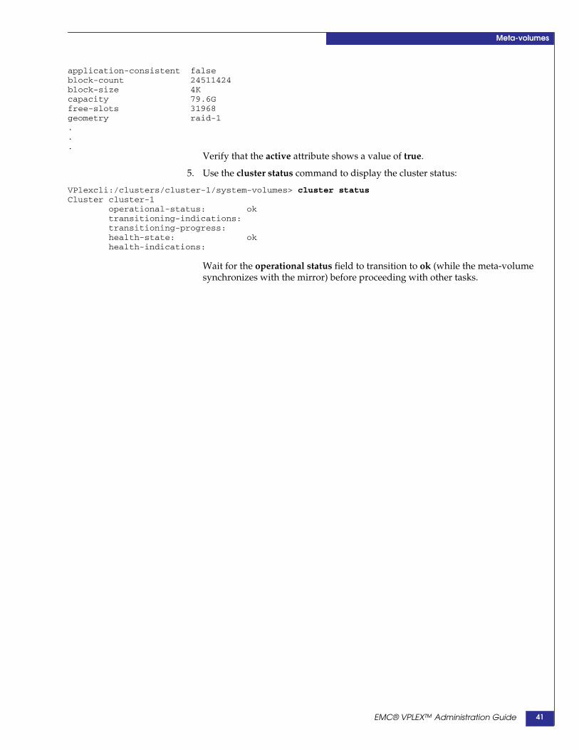
application-consistent falseblock-count 24511424block-size 4Kcapacity 79.6Gfree-slots 31968geometry raid-1...
Verify that the active attribute shows a value of true.
5. Use the cluster status command to display the cluster status:
VPlexcli:/clusters/cluster-1/system-volumes> cluster statusCluster cluster-1
operational-status: oktransitioning-indications:transitioning-progress:health-state: okhealth-indications:
Wait for the operational status field to transition to ok (while the meta-volumesynchronizes with the mirror) before proceeding with other tasks.
EMC® VPLEX™ Administration Guide 41

Meta-volumes
Back up the meta-volumeBackup creates a point-in-time copy of the current in-memory metadata withoutactivating it. The new meta-volume is named:
current-metadata-namebackup_yyyyMMMdd_HHmms
Create a backup meta-volume:
◆ As part of an overall system health check before a major migration or update
◆ If VPLEX permanently loses access to both meta-volumes
Back up the meta-volume: VPLEX Local
Before you beginIdentify two or more storage volumes to which to backup the metadata. Targetstorage volumes must be:
◆ Unclaimed
◆ 78 GB or larger
To back up the metadata for a single cluster configuration:
1. Use the ll command in device migration and extent migration contexts to verifythat there are no active migrations:
VPlexcli:/data-migrations/device-migrations> ll
VPlexcli:/data-migrations/extent-migrations> ll
If any migrations are in-progress or queued:
• Allow the migrations to complete, and commit them (see “Commit acompleted migration”); or
• Cancel the migrations (see “Cancel a migration (optional)”) and remove them(see “Clean a migration”).
EMC® VPLEX™ Administration Guide42
Meta-volumes
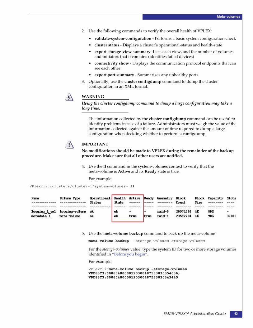
2. Use the following commands to verify the overall health of VPLEX:
• validate-system-configuration - Performs a basic system configuration check
• cluster status - Displays a cluster's operational-status and health-state
• export storage-view summary -Lists each view, and the number of volumesand initiators that it contains (identifies failed devices)
• connectivity show - Displays the communication protocol endpoints that cansee each other
• export port summary - Summarizes any unhealthy ports
3. Optionally, use the cluster configdump command to dump the clusterconfiguration in an XML format.
WARNING
Using the cluster configdump command to dump a large configuration may take along time.
The information collected by the cluster configdump command can be useful toidentify problems in case of a failure. Administrators must weigh the value of theinformation collected against the amount of time required to dump a largeconfiguration when deciding whether to perform a configdump.
IMPORTANT!No modifications should be made to VPLEX during the remainder of the backupprocedure. Make sure that all other users are notified.
4. Use the ll command in the system-volumes context to verify that themeta-volume is Active and its Ready state is true.
For example:
VPlexcli:/clusters/cluster-1/system-volumes> ll
5. Use the meta-volume backup command to back up the meta-volume
meta-volume backup --storage-volumes storage-volumes
For the storage-volumes value, type the system ID for two or more storage volumesidentified in “Before you begin”.
For example:
VPlexcli:meta-volume backup -storage-volumesVPD83T3:60060480000190300487533030354636,VPD83T3:60060480000190300487533030343445
EMC® VPLEX™ Administration Guide 43
Meta-volumes
Back up the meta-volume: VPLEX Metro or Geo
Before you beginIdentify two or more storage volumes at each cluster to which to back up themetadata. Target storage volumes must be:
◆ Unclaimed
◆ 78 GB or larger
Open a second Putty session to each cluster to display the client log files at/var/log/Vplex/cli directory. Use these sessions to watch for call home events.
To back up the meta-volume for a two-cluster VPLEX Metro or Geo:
1. Log in to each cluster.
2. At each cluster, use the ll command in device migration and extent migrationcontexts to verify that there are no active migrations:
VPlexcli:/data-migrations/device-migrations> llVPlexcli:/data-migrations/extent-migrations> ll
If any migrations are in-progress or queued:
• Allow the migrations to complete, and commit them (see “Commit acompleted migration”); or
• Cancel the migrations (see “Cancel a migration (optional)”) and remove them(see “Remove migration records”).
3. Use the following commands to verify the overall health of VPLEX:
• validate-system-configuration - Performs a basic system configuration check
• cluster status - Displays a cluster's operational-status and health-state
• export storage-view summary -Lists each view, and the number of volumesand initiators that it contains (identifies failed devices)
• connectivity show - Displays the communication protocol endpoints that cansee each other
• export port summary - Summarizes any unhealthy ports
4. Optionally, use the cluster configdump command to dump the clusterconfiguration in an XML format.
WARNING
Using the cluster configdump command to dump a large configuration may take along time.
The information collected by the cluster configdump command can be useful toidentify problems in case of a failure. Administrators must weigh the value of theinformation collected against the amount of time required to dump a largeconfiguration when deciding whether to perform a configdump.
IMPORTANT!No modifications should be made to VPLEX during the remainder of the backupprocedure. Make sure that all other users are notified.
5. At each cluster, use the ll command in the system-volumes context to verify thatthe status of the cluster’s meta-volume is Active and Ready state is true.
EMC® VPLEX™ Administration Guide44
Meta-volumes
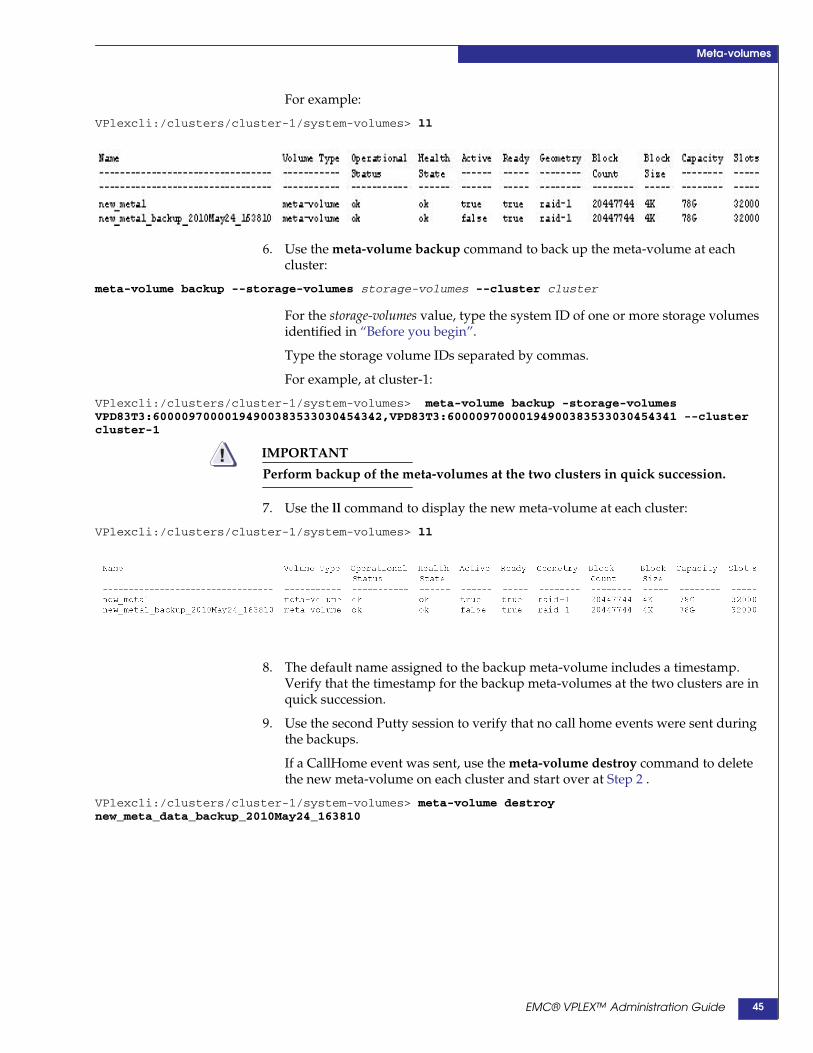
For example:
VPlexcli:/clusters/cluster-1/system-volumes> ll
6. Use the meta-volume backup command to back up the meta-volume at eachcluster:
meta-volume backup --storage-volumes storage-volumes --cluster cluster
For the storage-volumes value, type the system ID of one or more storage volumesidentified in “Before you begin”.
Type the storage volume IDs separated by commas.
For example, at cluster-1:
VPlexcli:/clusters/cluster-1/system-volumes> meta-volume backup -storage-volumesVPD83T3:60000970000194900383533030454342,VPD83T3:60000970000194900383533030454341 --clustercluster-1
IMPORTANT!Perform backup of the meta-volumes at the two clusters in quick succession.
7. Use the ll command to display the new meta-volume at each cluster:
VPlexcli:/clusters/cluster-1/system-volumes> ll
8. The default name assigned to the backup meta-volume includes a timestamp.Verify that the timestamp for the backup meta-volumes at the two clusters are inquick succession.
9. Use the second Putty session to verify that no call home events were sent duringthe backups.
If a CallHome event was sent, use the meta-volume destroy command to deletethe new meta-volume on each cluster and start over at Step 2 .
VPlexcli:/clusters/cluster-1/system-volumes> meta-volume destroynew_meta_data_backup_2010May24_163810
EMC® VPLEX™ Administration Guide 45
Meta-volumes
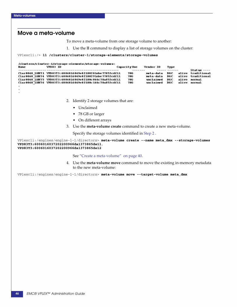
Move a meta-volumeTo move a meta-volume from one storage volume to another:
1. Use the ll command to display a list of storage volumes on the cluster:
VPlexcli:/> ll /clusters/cluster-1/storage-elements/storage-volumes
2. Identify 2 storage volumes that are:
• Unclaimed
• 78 GB or larger
• On different arrays
3. Use the meta-volume create command to create a new meta-volume.
Specify the storage volumes identified in Step 2 .
VPlexcli:/engines/engine-1-1/directors> meta-volume create --name meta_dmx --storage-volumesVPD83T3:6006016037202200966da1373865de11,VPD83T3:6006016037202200966da1373865de12
See “Create a meta-volume” on page 40.
4. Use the meta-volume move command to move the existing in-memory metadatato the new meta-volume:
VPlexcli:/engines/engine-1-1/directors> meta-volume move --target-volume meta_dmx
EMC® VPLEX™ Administration Guide46

Meta-volumes
Rename a meta-volumeBy default, meta-volume names are based on a timestamp. To change the name, dothe following:
1. Navigate to the /clusters/cluster/system-volumes/ context:
VPlexcli:/> cd clusters/cluster-2/system-volumes/
VPlexcli:/clusters/cluster-2/system-volumes>
2. Use the ll command to display the names of the meta-volumes.
3. Navigate to the /clusters/cluster/system-volumes/ target-meta-volume context.
For example:
VPlexcli:/clusters/cluster-1/system-volumes> cdnew_meta1_backup_2010May24_163810
4. Use the set name new_meta-volume_name command to change the name.
For example:
VPlexcli:/clusters/cluster-1/system-volumes/new_meta1_backup_2010May24_163810> set name backup_May24_pre_refresh
EMC® VPLEX™ Administration Guide 47

Meta-volumes
Delete a meta-volume
IMPORTANT!A meta-volume must be inactive in order to be deleted. Attempts to delete an activemeta-volume fail with an error message.
To delete a meta-volume, do the following:
1. Navigate to the target volume’s context.
For example:
cd clusters/cluster-1/system-volumes/metadata_1/
2. Use the ll command to verify that the volume is not active.
For example:
/clusters/cluster-1/system-volumes/metadata_1> ll
Attributes:Name Value---------------------- -----------active falseapplication-consistent falseblock-count 23592704block-size 4K...
3. Use the meta-volume destroy --meta-volume meta-volume command to deletethe specified meta-volume.
For example:
meta-volume destroy --meta-volume metadata_1
A warning message appears:
Meta-volume 'metadata_1' will be destroyed. Do you wish to continue?(Yes/No)
4. Type y.
EMC® VPLEX™ Administration Guide48

Meta-volumes
Display meta-volumeUse the ll command to display status for a meta-volume:
VPlexcli:/clusters/cluster-1/system-volumes/ICO_META_1_1_Metadata> ll
/clusters/cluster-1/system-volumes/ICO_META_1_1_Metadata:
Attributes:Name Value---------------------- -------------active trueapplication-consistent falseblock-count 24511424block-size 4Kcapacity 79.5Gcomponent-count 2free-slots 31968geometry raid-1health-indications []health-state oklocality localoperational-status okready truerebuild-allowed truerebuild-eta -rebuild-progress -rebuild-status donerebuild-type fullslots 32000stripe-depth -system-id ICO_META_1_1_Metadatatransfer-size 2Mvolume-type meta-volume
Contexts:Name Description---------- -------------------------------------------------------------------components The list of components that support this device or system virtual
volume.Use the ll components/ command to display the component volumes of themeta-volume:
VPlexcli:/clusters/cluster-2/system-volumes/ICO_META_1_1_Metadata> ll components/
/clusters/cluster-2/system-volumes/clus2_MetaVol/components:Name Slot Type Operational Health Capacity---------------------------------------- Number -------------- Status State ------------------------------------------------ ------ -------------- ----------- ------ --------VPD83T3:60000970000192601707533031333136 0 storage-volume ok ok 78GVPD83T3:60060480000190300487533030343445 1 storage-volume ok ok 78G
Table 1 meta-volume display fields
Field Description
active Indicates whether this is the currently-active metadata volume. The system has only oneactive metadata volume at a time.
application-consistent Whether or not this storage-volume is application-consistent.
block-count The number of blocks in the volume.
EMC® VPLEX™ Administration Guide 49
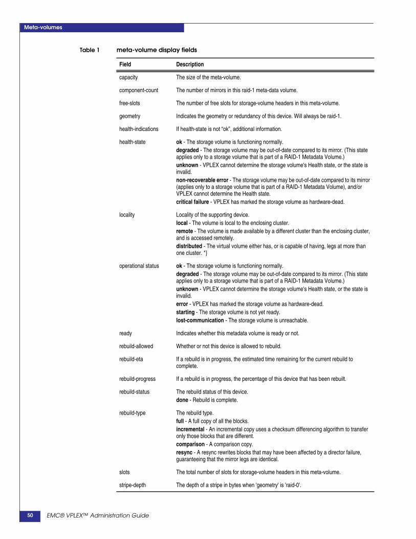
Meta-volumes
capacity The size of the meta-volume.
component-count The number of mirrors in this raid-1 meta-data volume.
free-slots The number of free slots for storage-volume headers in this meta-volume.
geometry Indicates the geometry or redundancy of this device. Will always be raid-1.
health-indications If health-state is not “ok”, additional information.
health-state ok - The storage volume is functioning normally.degraded - The storage volume may be out-of-date compared to its mirror. (This stateapplies only to a storage volume that is part of a RAID-1 Metadata Volume.)unknown - VPLEX cannot determine the storage volume's Health state, or the state isinvalid.non-recoverable error - The storage volume may be out-of-date compared to its mirror(applies only to a storage volume that is part of a RAID-1 Metadata Volume), and/orVPLEX cannot determine the Health state.critical failure - VPLEX has marked the storage volume as hardware-dead.
locality Locality of the supporting device.local - The volume is local to the enclosing cluster.remote - The volume is made available by a different cluster than the enclosing cluster,and is accessed remotely.distributed - The virtual volume either has, or is capable of having, legs at more thanone cluster. *}
operational status ok - The storage volume is functioning normally.degraded - The storage volume may be out-of-date compared to its mirror. (This stateapplies only to a storage volume that is part of a RAID-1 Metadata Volume.)unknown - VPLEX cannot determine the storage volume's Health state, or the state isinvalid.error - VPLEX has marked the storage volume as hardware-dead.starting - The storage volume is not yet ready.lost-communication - The storage volume is unreachable.
ready Indicates whether this metadata volume is ready or not.
rebuild-allowed Whether or not this device is allowed to rebuild.
rebuild-eta If a rebuild is in progress, the estimated time remaining for the current rebuild tocomplete.
rebuild-progress If a rebuild is in progress, the percentage of this device that has been rebuilt.
rebuild-status The rebuild status of this device.done - Rebuild is complete.
rebuild-type The rebuild type.full - A full copy of all the blocks.incremental - An incremental copy uses a checksum differencing algorithm to transferonly those blocks that are different.comparison - A comparison copy.resync - A resync rewrites blocks that may have been affected by a director failure,guaranteeing that the mirror legs are identical.
slots The total number of slots for storage-volume headers in this meta-volume.
stripe-depth The depth of a stripe in bytes when 'geometry' is 'raid-0'.
Table 1 meta-volume display fields
Field Description
EMC® VPLEX™ Administration Guide50

Meta-volumes
system-id Name assigned to the meta-volume.
transfer-size The transfer size during rebuild in bytes. See “About transfer-size” on page 111.
volume-type For meta-volumes, this is always 'meta-volume'.
Table 1 meta-volume display fields
Field Description
EMC® VPLEX™ Administration Guide 51

Meta-volumes
EMC® VPLEX™ Administration Guide52

4
Topics described in this chapter include:
◆ SPS battery conditioning................................................................. 54◆ Battery conditioning cycle calendar ................................................ 54◆ When it is safe to start a conditioning cycle ................................... 55◆ When to stop a conditioning cycle................................................... 56◆ Additional documentation................................................................ 56
◆ Call-home notifications and system reporting............................ 57◆ Additional documentation................................................................ 58
◆ Event log locations ............................................................................ 60
◆ Compare and Write (hardware acceleration) ............................... 61◆ Enabling/disabling CAW ................................................................. 61◆ CAW statistics..................................................................................... 63
System Management
EMC® VPLEX™ GeoSynchrony 5.1 Administrator’s Guide 53

System Management
SPS battery conditioningA standby power supply (SPS) battery conditioning cycle consists of a 5 minuteperiod of on-battery operation followed by 6 hours of recharge.
Battery conditioning verifies the health of the batteries and extends their operationallife.
Each SPS battery in a VPLEX system is automatically conditioned once a month.
Battery conditioning is enabled by default, but can be disabled for some activities(maintenance, system upgrades) where both SPS units are required.
In addition to the monthly automatic conditioning cycles, manually requestedconditioning cycles can be scheduled and cancelled.
Battery conditioning cycle calendarThe conditioning cycle effectively moves the target battery into discharge state. Theautomatic conditioning cycle is scheduled so as not to have more than one activebattery conditioning cycle (and thus more than one battery in discharge state) at anyone time.
In addition to automatic battery conditioning cycles, additional cycles can bemanually requested.
Automatic battery conditioning cycles are "checker boarded" into 6 hour windows:
◆ An SPS on the A side is scheduled to run in the first window, followed by
◆ A window that allows manual tests on the A side, followed by
◆ An SPS on the B side, followed by
◆ A window that allows manual tests on the B side SPS.
Time windows for manual tests allow only one side (A or B) to run conditioningcycles in a given period.
Figure 1 shows the conditioning cycle calendar for a typical month:
EMC® VPLEX™ GeoSynchrony 5.1 Administrator’s Guide54

System Management
Figure 1 Typical monthly battery conditioning schedule
When it is safe to start a conditioning cycle
CAUTION!If an SPS is put on battery power when it is unsafe to do so, the risk of dataunavailability and data loss is increased.
There are several conditions that must be met in order to safely start a conditioningcycle:
◆ The SPS must have 6 hours to fully charge before the allotted conditioning timeexpires. Conditioning cycles (including manually requested cycles) start at thebeginning of their scheduled time slot.
◆ The SPS must not have failed a previous conditioning cycle or have any internalfailures.
◆ All power components in the engine related to the SPS must be healthy.
EMC® VPLEX™ GeoSynchrony 5.1 Administrator’s Guide 55

System Management
◆ No maintenance, hardware replacement, or system upgrade can occur during aconditioning cycle.
Starting a conditioning cycle during maintenance or system upgrades coulddisrupt these operations.
When to stop a conditioning cycleStop a conditioning cycle once it has started when:
◆ A power component in the associated engine becomes unhealthy.
This could be a hardware fault in one of the engine's director power supplies or apower loss in the peer SPS.
A power disruption automatically aborts any ongoing SPS conditioning.
◆ Manual intervention is required due to unscheduled maintenance or animpending disaster.
If an SPS that is currently being conditioned loses AC power, the engine willbehave normally and continue to be powered by the peer SPS.
Additional documentationRefer to the VPLEX CLI Guide for information about the CLI commands related tobattery conditioning:
◆ battery-conditioning set-schedule - Sets the battery conditioning schedule (dayof week) for backup battery units on a cluster.
◆ battery-conditioning enable - Enables conditioning on the specified backupbattery unit(s).
◆ battery-conditioning disable - Disables battery conditioning on the specifiedbackup battery unit(s).
◆ battery-conditioning manual-cycle request - Manually requests a batteryconditioning cycle on the specified backup battery unit.
◆ battery-conditioning manual-cycle cancel-request - Cancels a manuallyrequested battery conditioning cycle on the specified backup battery unit.
◆ battery-conditioning summary - Displays a summary of the battery conditioningschedule for all devices, grouped by cluster.
Refer to the VPLEX Procedure Generator for the procedures to:
◆ Set the battery conditioning schedule
◆ Enable battery conditioning
◆ Disable battery conditioning
◆ Manually request an additional conditioning cycle
◆ Cancel a manually requested cycle
EMC® VPLEX™ GeoSynchrony 5.1 Administrator’s Guide56
System Management
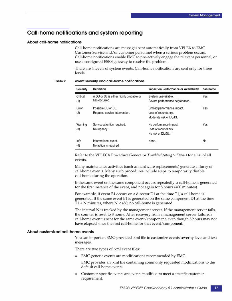
Call-home notifications and system reporting
About call-home notificationsCall-home notifications are messages sent automatically from VPLEX to EMCCustomer Service and/or customer personnel when a serious problem occurs.Call-home notifications enable EMC to pro-actively engage the relevant personnel, oruse a configured ESRS gateway to resolve the problem.
There are 4 levels of system events. Call-home notifications are sent only for threelevels:
Refer to the VPLECX Procedure Generator Troubleshooting > Events for a list of allevents.
Many maintenance activities (such as hardware replacements) generate a flurry ofcall-home events. Many such procedures include steps to temporarily disablecall-home during the operation.
If the same event on the same component occurs repeatedly, a call-home is generatedfor the first instance of the event, and not again for 8 hours (480 minutes).
For example, if event E1 occurs on a director D1 at the time T1, a call-home isgenerated. If the same event E1 is generated on the same component D1 at the timeT1 + N minutes, where N < 480, no call-home is generated.
The interval N is tracked by the management server. If the management server fails,the counter is reset to 8 hours. After recovery from a management server failure, acall-home event is sent for the same event/component, even though 8 hours may nothave elapsed since the first call-home for that event/component.
About customized call-home eventsYou can import an EMC-provided .xml file to customize events severity level and textmessages.
There are two types of .xml event files:
◆ EMC-generic events are modifications recommended by EMC.
EMC provides an .xml file containing commonly requested modifications to thedefault call-home events.
◆ Customer-specific events are events modified to meet a specific customerrequirement.
Table 2 event severity and call-home notifications
Severity Definition Impact on Performance or Availability call-home
Critical(1)
A DU or DL is either highly probable orhas occurred.
System unavailable.Severe performance degradation.
Yes
Error(2)
Possible DU or DL.Requires service intervention.
Limited performance impact.Loss of redundancy.Moderate risk of DU/DL.
Yes
Warning(3)
Service attention required.No urgency.
No performance impact.Loss of redundancy.No risk of DU/DL.
Yes
Info(4)
Informational event.No action is required.
None. No
EMC® VPLEX™ GeoSynchrony 5.1 Administrator’s Guide 57
System Management
EMC provides a custom events file developed by EMC engineering and appliedby EMC Technical Support.
Call-home behaviors changes immediately when the modified events file is applied.
If a customized events file is already applied, applying a new file overrides theexisting file.
If the same event is modified in the customer-specific and EMC-generic file, themodification specified for that event in the customer-specific file is applied.
If call-home is disabled when the custom events file is applied, the modified eventsare saved and applied when call-home is enabled.
About system (SYR) reportingSystem reporting (SYR) collects and transmits two types of information from VPLEXsystems to EMC:
◆ System reports - Sent once weekly to the EMC System Reports database. Systemreports include information about the configuration and state of the system.
◆ System alerts - Sent in real-time through a designated SMTP server to the EMC.Alerts are filtered as to whether a service request should be opened with EMCCustomer Service. If a service request is required, it is opened automatically.
SYR is enabled by default, but can be disabled at any time through the GUI or CLI.
Modify call-home and SYRCall-home and SYR settings are typically configured during system set-up.
Use the to configuration event-notices-reports-config CLI command to configure thecall-home and/or SYR settings if they were not configured during the initialinstallation.
The command runs an interview script that prompts for the required information. Ifeither call-home or SYR is not configured, interview questions to configure theservice that is not configured are displayed.
If both call-home and SYR are already configured, the current configurationinformation is displayed.
Before you beginYou will need the following information to complete configuration of call-home andSYR reporting:
◆ IP address of the primary SMTP server used to forward reports to EMC. EMCrecommends using your ESRS gateway as the primary connection address.
◆ (Optional) One or more IP addresses of secondary SMTP server(s) used toforward reports to EMC if the primary server fails. These addresses must bedifferent than the address for the primary SMPTP server.
◆ (Optional) One or more e-mail addresses of personnel who should receive e-mailnotifications when events occur.
Additional documentationRefer to the VPLEX Procedure Generator for the procedures to:
◆ Configure call-home and SYR reporting
◆ Modify the call-home and SYR configuration
EMC® VPLEX™ GeoSynchrony 5.1 Administrator’s Guide58
System Management
◆ Import/apply a custom call-home events file
◆ Remove a custom call-home events file
◆ Display modified call-home events
◆ Display whether call-home is enabled
◆ Disable call-home
◆ Enable call-home
◆ Send a test call-home notification
◆ Display SYR collection time
◆ Disable SYR collection
◆ Modify SYR collection time
Refer to the VPLEX CLI Guide for information about the CLI commands related tocall-home notifications and SYR reporting:
◆ configuration event-notices-reports-config - Configure call-home and SYRsettings after the initial configuration of VPLEX,
◆ configuration event-notices-reports-reset - Resets the current event notificationand reporting configuration.
◆ notifications call-home import-event-modification - Imports and appliesmodified call-home events.
◆ notifications call-home remove-event-modifications - Removes customizedcall-home events files, including customer-specific modifications andmodifications recommended by EMC.
◆ notifications call-home view-event-modifications - Displays any customizedcall-home events.
EMC® VPLEX™ GeoSynchrony 5.1 Administrator’s Guide 59
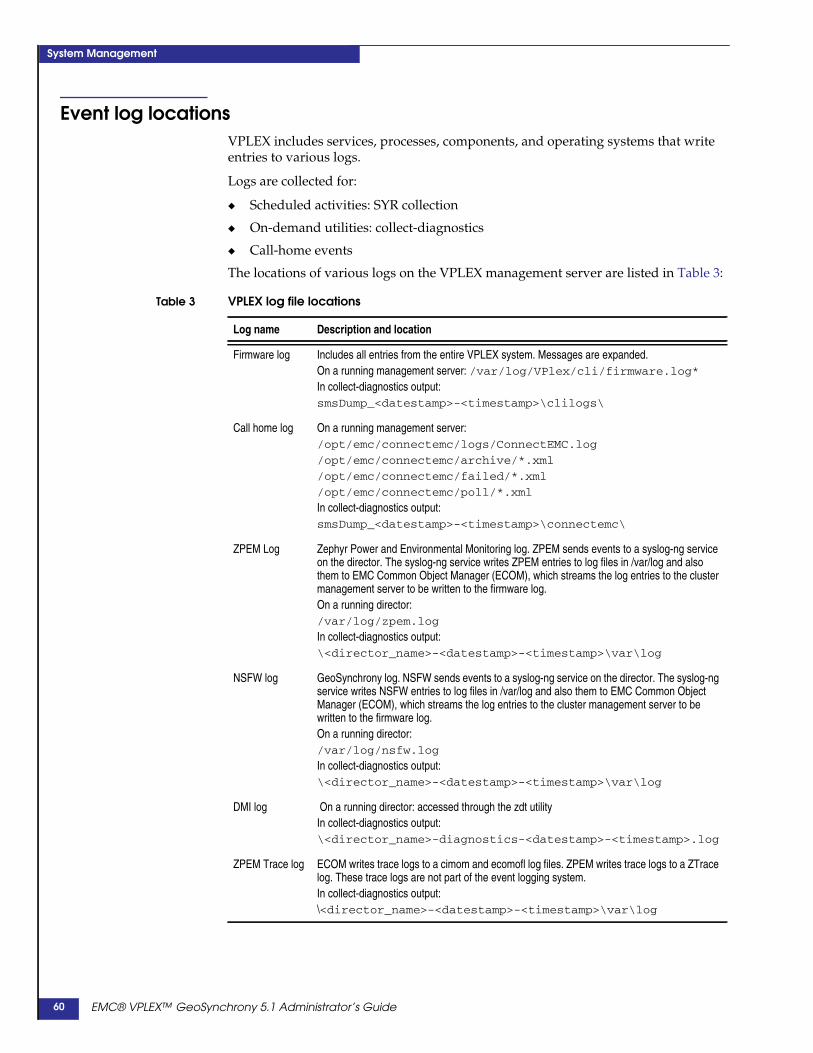
System Management
Event log locationsVPLEX includes services, processes, components, and operating systems that writeentries to various logs.
Logs are collected for:
◆ Scheduled activities: SYR collection
◆ On-demand utilities: collect-diagnostics
◆ Call-home events
The locations of various logs on the VPLEX management server are listed in Table 3:
Table 3 VPLEX log file locations
Log name Description and location
Firmware log Includes all entries from the entire VPLEX system. Messages are expanded.On a running management server: /var/log/VPlex/cli/firmware.log*In collect-diagnostics output:smsDump_<datestamp>-<timestamp>\clilogs\
Call home log On a running management server:/opt/emc/connectemc/logs/ConnectEMC.log
/opt/emc/connectemc/archive/*.xml
/opt/emc/connectemc/failed/*.xml
/opt/emc/connectemc/poll/*.xml
In collect-diagnostics output:smsDump_<datestamp>-<timestamp>\connectemc\
ZPEM Log Zephyr Power and Environmental Monitoring log. ZPEM sends events to a syslog-ng serviceon the director. The syslog-ng service writes ZPEM entries to log files in /var/log and alsothem to EMC Common Object Manager (ECOM), which streams the log entries to the clustermanagement server to be written to the firmware log.On a running director:/var/log/zpem.log
In collect-diagnostics output:\<director_name>-<datestamp>-<timestamp>\var\log
NSFW log GeoSynchrony log. NSFW sends events to a syslog-ng service on the director. The syslog-ngservice writes NSFW entries to log files in /var/log and also them to EMC Common ObjectManager (ECOM), which streams the log entries to the cluster management server to bewritten to the firmware log.On a running director:/var/log/nsfw.log
In collect-diagnostics output:\<director_name>-<datestamp>-<timestamp>\var\log
DMI log On a running director: accessed through the zdt utilityIn collect-diagnostics output:\<director_name>-diagnostics-<datestamp>-<timestamp>.log
ZPEM Trace log ECOM writes trace logs to a cimom and ecomofl log files. ZPEM writes trace logs to a ZTracelog. These trace logs are not part of the event logging system.In collect-diagnostics output:\<director_name>-<datestamp>-<timestamp>\var\log
EMC® VPLEX™ GeoSynchrony 5.1 Administrator’s Guide60
System Management
Compare and Write (hardware acceleration)The CompareAndWrite (CAW) SCSI command is used to coordinate VMwareoperations such as powering-on/off Virtual Machines, moving VMs from one ESX toanother without halting applications (VMotion), and Distributed Resource Scheduler(DRS) operations.
CAW is used by VMWare ESX servers to relieve storage contention, which may becaused by SCSI RESERVATION in distributed VM environments. CAW assistsstorage hardware acceleration by allowing ESX servers to lock a region of diskinstead of entire disk.
ESX 5.0 servers use this strategy to increase the number of VMs an ESX servers canhost, and to increase the performance of those VMs.
Starting in GeoSynchrony 5.1, VPLEX support for CAW is enabled by default.
Enabling/disabling CAW
CAUTION!CAW can be enabled/disabled on VPLEX only by EMC Technical Supportpersonnel.
VMware servers discover whether the CAW SCSI command is supported:
◆ During initial storage scanning
◆ When the VMFS3.HardwareAcceleratedLocking value on the ESX host is enabled(or toggled if it is enabled)
Note: To toggle the value: In the vSphere client, toggle host > Configuration > Software >Advanced Settings > VMFS3.HardwareAcceleratedLocking value to 0 and then 1.
If CAW is not supported or support is disabled, VPLEX returns CHECKCONDITION, ILLEGAL REQUEST, and INVALID OP-CODE. The ESX server revertsto using SCSI RESERVE and the VM operation continues.
VM operations may experience significant performance degradation if CAW is notenabled.
VPLEX enables CAW to be enabled/disabled for all storage associated with VPLEX,using a single command. When CAW is disabled on VPLEX, VPLEX storage volumes,do not include CAW support information in their responses to inquiries from hosts.
To mark storage CAW disabled:
◆ VMFS3.HardwareAcceleratedLocking must be toggled, or
◆ Hosts may need to rescan their storage.
CAUTION!Enabling/disabling CAW functionality supports exceptional situations such asassisting EMC Technical Support personnel to diagnose a problem. CAW isenabled by default and should be disabled only by EMC Technical Support.
Support for CAW can be enabled or disabled at two levels:
EMC® VPLEX™ GeoSynchrony 5.1 Administrator’s Guide 61

System Management
◆ storage-view - Enabled or disabled for all existing storage views. A storage viewcreated after CAW is enabled/disabled at the storage view level inherits thesystem default setting. EMC recommends maintaining uniform CAW setting onall storage views in VPLEX. If CAW must be disabled for a given storage view, itmust be disabled on all existing and future storage views. To make future storageviews to reflect the new setting, change the system default (described below).
◆ system default - Enabled or disabled as a system default. A storage view createdafter CAW is enabled/disabled at the system default level inherits the systemdefault setting. If the system default is enabled, CAW support for the new storageview is also enabled
Display CAW settingUse the ls command in /clusters/cluster/exports/storage-views context to displaywhether CAW is enabled at the storage view level. For example:
VPlexcli:/> ll /clusters/cluster-2/exports/storage-views/*
/clusters/cluster-2/exports/storage-views/FE-Logout-test:Name Value------------------------ -----------------------------------------------------------------caw-enabled false.../clusters/cluster-2/exports/storage-views/default_quirk_view:Name Value------------------------ ------------------------------------------caw-enabled false...
Use the ls command in /clusters/cluster context to display the CAW system defaultsetting:
VPlexcli:/> ls /clusters/cluster-1
/clusters/cluster-1:
Attributes:Name Value---------------------- --------------------------------------------allow-auto-join trueauto-expel-count 0auto-expel-period 0auto-join-delay 0cluster-id 1connected truedefault-cache-mode synchronousdefault-caw-template true...
Enable/disable CAW for a storage viewUse the set command in /clusters/cluster/exports/storage-views/storage-viewcontext to enable or disable CAW for the storage view.
To enable CAW for a storage view:
VPlexcli:/clusters/cluster-1/exports/storage-views/recoverpoint_vols>set caw-enabled true
To disable CAW for a storage view:
EMC® VPLEX™ GeoSynchrony 5.1 Administrator’s Guide62

System Management
VPlexcli:/clusters/cluster-1/exports/storage-views/recoverpoint_vols>set caw-enabled false
Enable/disable CAW as system defaultUse the set command in /clusters/cluster context to enable or disable CAW for theentire cluster.
To enable CAW as the cluster system default:
VPlexcli:/clusters/cluster-1> set default-caw-template true
To disable CAW as the cluster system default:
VPlexcli:/clusters/cluster-1> set default-caw-template false
CAW statisticsCAW performance statistics are included for front-end volume (fe-lu), front-end port(fe-prt), and front-end director (fe-director) targets.
See Front-end volume (fe-lu) statistics on page 256, Front-end port (fe-prt) statisticson page 256, and Front-end director (fe-director) statistics on page 255
Statistics for fe-director targets are collected as a part of the automatically createdperpetual monitor.
You can create a monitor to collect CAW statistics, which can be especially useful forfe-lu targets (because there can be very large numbers of volumes involved, thesestatistics are not always collected). See Example: Send CAW statistics to themanagement server on page 240
EMC® VPLEX™ GeoSynchrony 5.1 Administrator’s Guide 63

System Management
EMC® VPLEX™ GeoSynchrony 5.1 Administrator’s Guide64

5
Distributed devices have their underlying storage arrays located at both clusters in aVPLEX Metro or VPLEX Geo.
Distributed devices support virtual volumes, that are presented to a host through astorage view. From the host, the virtual volumes appear as single volumes located ona single array.
You can configure up to 8000 distributed devices in a VPLEX system. That is, the totalnumber of distributed virtual volumes plus the number of top-level local devicesmust not exceed 8000.
All distributed devices must be associated with a logging volume. During a linkoutage, the logging volume is used to map the differences between the legs of a DR1.
When the link is restored, the legs are resynchronized using the contents of theirlogging volumes.
All distributed devices must have a detach rule-set to determine which clustercontinues I/O when connectivity between clusters is lost.
This chapter describes the topics and procedures:
◆ Additional documentation................................................................ 66◆ Logging volumes................................................................................ 67◆ Rule-sets............................................................................................... 70◆ Configure distributed devices .......................................................... 79◆ Create a virtual volume on a distributed device ........................... 85◆ Expose a virtual volume to a remote host ...................................... 89◆ Add a local mirror to distributed device ........................................ 90◆ Remove a local mirror from a distributed device.......................... 92◆ Create a distributed device from an exported volume................. 93◆ Display/enable/disable automatic device rebuilds ..................... 94◆ Configure I/O resumption after a network outage ...................... 96
Distributed devices
EMC® VPLEX™ Administration Guide 65

Distributed devices
Additional documentation◆ Refer to the EMC VPLEX CLI Guide for detailed information about the CLI
commands to create and manage distributed devices.
◆ Refer to the EMC VPLEX Product Guide for general information about distributeddevices.
◆ Refer to the VPLEX Procedure Generator for the following procedures:
• Expand a distributed GeoSynchrony volume
• Move a logging volume
• Convert a local synchronous volume to an asynchronous DR1
EMC® VPLEX™ Administration Guide66

Distributed devices
Logging volumesThis section describes the following topics:
◆ “About logging volumes” on page 67
◆ “Logging volume size” on page 67
◆ “Create a logging volume” on page 68
◆ “Add a mirror to a logging volume” on page 68
◆ “Delete a logging volume” on page 69
About logging volumesLogging volumes are required at each cluster before a distributed device can becreated.
Logging volumes keep track of blocks written during:
◆ An inter-cluster link outage, or
◆ When one leg of a DR1 becomes unreachable and then recovers.
After the inter-cluster link or leg is restored, the VPLEX system uses the informationin logging volumes to synchronize the mirrors by sending only changed blocks acrossthe link.
Logging volumes also track changes during loss of a volume when that volume is onemirror in a distributed device.
Note: Logging volumes are not used to optimize re-syncs on local RAID-1s.
Single-cluster systems and systems that do not have distributed devices do notrequire logging volumes.
During and after link outages, logging volumes are subject to high levels of I/O.Thus, logging volumes must be able to service I/O quickly and efficiently.
EMC recommends:
◆ Place logging volumes on the fastest storage available.
◆ Stripe logging volumes across several disks to accommodate the high level of I/Othat occurs during and after link outages.
◆ Mirror logging volumes across two or more back-end arrays, as they are critical torecovery after the link is restored.
Arrays for mirroring logging volumes should be chosen such that they will notneed to migrate at the same time.
Logging volume sizeLogging volumes must be sized as follows:
One bit for every page of distributed storage space.
For example, for a VPLEX Metro configuration with 160 TB of distributed devices, thelogging volumes at each cluster should be sized ~ 10 GB.
EMC® VPLEX™ Administration Guide 67
Distributed devices
Create a logging volumeTo create a logging volume, first claim the storage volumes that will be used, andcreate extents from those volumes.
◆ Use the ll /clusters/cluster/storage-elements/ storage-volumes command todisplay the available storage volumes on the cluster.
◆ Use the storage-volume claim -n storage-volume_name command to claim one ormore storage volumes.
◆ Use the extent create -d storage-volume_name, storage-volume_name commandto create an extent to use for the logging volume.
Repeat this step for each extent to be used for the logging volume.
Use the logging-volume create command to create a logging volume. The syntax forthe command is:
logging-volume create --name name --geometry [raid-0 |raid-1]--extents context-path --stripe-depth
--name - The name for the new logging volume.
--geometry - The geometry for the new volume. Valid values are raid-0 or raid-1.
--extents - Context paths to one or more extents to use to create the logging volume.Target extents must not be empty, and must all reside at the specified cluster.
--stripe-depth - Required if --geometry is raid-0. Stripe depth must be:
◆ Greater than zero, but not greater than the number of blocks of the smallestelement of the RAID 0 device being created
◆ A multiple of 4 K bytes
A depth of 32 means 128 K (32 x 4K) is written to the first disk, and then the next 128K is written to the next disk.
Concatenated RAID devices are not striped.
Best practice regarding stripe depth is to follow the best practice of the underlyingarray.
For example:
VPlexcli:/> cd clusters/cluster-1/system-volumes/VPlexcli:/clusters/cluster-1/system-volumes> logging-volume create --name cluster_1_log_vol--geometry raid-0 --extents extent_1 , extent_2 --stripe-depth 1
Add a mirror to a logging volumeTo display the name of the logging volume for the current cluster, navigate to thesystem volume context and type ll:
VPlexcli:/> cd clusters/cluster-1/system-volumes/
VPlexcli:/clusters/cluster-1/system-volumes> ll
Name Volume Type Operational Health Active Ready Geometry Block Block Capacity Slots-------- -------------- Status State ------ ----- -------- Count Size -------- ------------- -------------- ----------- ------ ------ ----- -------- -------- ----- -------- -----log1_vol logging-volume ok ok - - raid-1 20448000 4K 78G -meta_1 meta-volume ok ok true true raid-1 20447744 4K 78G 3200
Use the logging-volume add-mirror command to add a mirror to the specifiedlogging volume. The syntax for the command is:
EMC® VPLEX™ Administration Guide68

Distributed devices
logging-volume add-mirror --logging-volume logging-volume --mirror mirror
--logging-volume - Name of logging volume to which to add the mirror.
--mirror - The name or context path of the device or storage-volume extent to act as amirror. Must be a top-level device or a storage-volume extent.
For example:
VPlexcli:/clusters/cluster-1/system-volumes>logging-volume add-mirror --logging-volumelog1_vol --mirror /clusters/cluster-2/ storage-elements/extents/extent_Symm2194_20F0_1
Delete a logging volumeUse the logging-volume destroy --logging-volume logging-volume command todelete the specified logging volume.
For example:
VPlexcli:/clusters/<cluster-n>/system-volumes>logging-volume destroy --logging-volumecluster_6_log_vol
EMC® VPLEX™ Administration Guide 69

Distributed devices
Rule-setsThis section describes the following topics:
◆ “About rule-sets” on page 70
◆ “Create a rule-set” on page 73
◆ “Add rules to a rule-set” on page 73
◆ “Attach a rule-set to a distributed device” on page 74
◆ “Modify the rule-set attached to a distributed device” on page 75
◆ “Attach a rule-set to a local device” on page 76
◆ “Verify a rule-set’s configuration” on page 76
◆ “Detach a rule-set from a device” on page 77
◆ “Remove all rules from all distributed devices” on page 77
◆ “Copy a rule-set” on page 78
◆ “Delete a rule-set” on page 78
About rule-sets Rule-sets are predefined rules that determine which cluster continues I/O whenconnectivity between clusters is lost. Rule-set apply to devices that are not membersof consistency groups.
A cluster loses connectivity to its peer cluster when:
◆ The inter-cluster link fails,
◆ The peer cluster fails.
Note: The cluster expel command also causes clusters to lose connectivity to one another.
When a loss of connectivity occurs, VPLEX:
◆ Suspends I/O to all distributed devices on both clusters, and
◆ Starts a delay timer.
If connectivity is not restored when the timer expires (default is 5 seconds), VPLEX:
◆ Resumes I/O on the leg of the distributed device (the “winning” cluster) asdetermined by the device’s rule-set
◆ Keeps I/O suspended on the other leg (the “losing” cluster).
Writes to the distributed device from the losing cluster are suspended untilconnectivity is restored.
When the inter-cluster link is restored, the I/O written to the winning cluster isre-synchronized to the losing cluster.
The rules for determining the number of seconds to wait, which leg of a distributeddevice is resumed, and which remains suspended are contained in rule-sets.
A rule-set consists of a container (the rule-set) and one rule.
Rules have two attributes:
◆ Delay - The number of seconds between the link outage and when the actionsdefined by the rule-set (resume I/O to the winning cluster, keep I/O to the losingcluster suspended) begin. The default is 5 seconds.
EMC® VPLEX™ Administration Guide70

Distributed devices
◆ Cluster - The cluster on which I/O resumes (the winning cluster).
All distributed devices must have a rule-set. A cluster may be the “winning” clusterfor some distributed devices, and the “losing” cluster for other distributed devices.
Most I/O workloads require specific sets of virtual volumes to resume on one clusterand remain suspended on the other cluster.
VPLEX includes two default rule-sets:
EMC recommends that only the two default rule-sets be applied to distributeddevices.
The default value of a distributed device’s rule-set is determined by the managementserver on which the device was created.
If a device is created on the management server for cluster-1, the default rule-set forthat device is cluster-1-detaches.
Rule-sets are located in the distributed-storage/rule-sets context.
Rules are located under their rule-set context.
Auto-resume When cluster connectivity is restored, subsequent behavior is determined by theauto-resume attribute for the distributed device.
◆ If auto-resume is set to false, the distributed device on the losing cluster remainssuspended until I/O is manually resumed by the system administrator (using thedevice resume-link-up command).
◆ If auto-resume is set to true, I/O may start immediately after the link is restored.
After I/O is resumed to the mirror leg on the losing cluster, any data written to thedevice on the winning cluster during the outage is resynchronized from the leg on thewinning cluster.
Use the set command to configure a device’s auto-resume attribute.
Force I/O to resume on a suspended legTwo commands allow administrators to force I/O to resume on a suspended mirrorleg:
◆ device resume-link-down - Used when the inter-cluster link is down. Allowssuspended mirror legs to resume I/O immediately.
For example, use this command if the peer cluster is the winning cluster but isknown to have failed.
◆ device resume-link-up - Used after the link has been restored.
For example, use this command to the restart I/O to the mirror leg on the losingcluster when the auto-resume flag is set to false.
Rule-set best practices◆ Use the provided pre-configured rule-sets whenever possible.
Table 4 Default rule-sets
Rule-set name Cluster-1 Cluster-2
cluster-1-detaches Services I/O Suspends I/O
cluster-2-detaches Suspends I/O Services I/O
EMC® VPLEX™ Administration Guide 71

Distributed devices
◆ For custom rule-sets, leave the detach delay timer at the default value of 5seconds.
Setting the detach delay lower than 5 seconds can result in unnecessary clusterdetaches during periods of network instability. Multiple cluster detaches in ashort period of time can result in unnecessary data rebuilds and reducedperformance.
Consult EMC Customer Support if a lower detach time is required.
◆ Configure detach rules based on the cluster/site that is expected to continue I/Oduring an outage.
◆ Avoid conflicting detach configurations. It is important to understand whichcluster is configured to automatically detach.
◆ Document how rule sets are applied.
It is acceptable for different distributed devices to resume I/O on differentclusters during an outage.
CAUTION!If a host application uses more than one distributed device, all distributed devicesfor that application should have the same rule-set (to resume I/O on the samecluster).
Caution: conflicted detachThe major problem to avoid when creating and using rule-sets is a scenario referredto as a conflicted detach. Conflicted detach happens during a network outage when:
◆ Both legs of a distributed device perform I/O independently.
◆ Both clusters write to the different legs of the same virtual volume.
◆ When connectivity is restored, the administrator picks the winner cluster,meaning that one of the legs is used as the source to rebuild.
◆ Logging synchronizes the losing cluster to match the winning cluster.
◆ Any data written to the losing cluster during the network communication outageis overwritten.
Rule-sets and manual detaches must not result in conflicting detaches. Conflictingdetaches result in lost data (on the losing cluster), a full rebuild and degradedperformance during the full rebuild.
Rule-sets and local devicesA rule-set can be applied to a local device when the device’s visibility is set to global.
Attaching a rule-set to a local device:
◆ Enables the cluster to detach in the event of a link outage
◆ Allows I/O to continue at the detached cluster.
VPLEX islands Rule-sets introduce the term “island”. An island is a set of communicating clusters.
A single cluster can be an island by itself.
For 2 clusters, there are 3 possible combinations, each of which can be an island.
◆ cluster-1
◆ cluster-2
EMC® VPLEX™ Administration Guide72

Distributed devices
◆ cluster-1 and cluster-2
For VPLEX Metro and Geo configurations, islands are mostly synonymous withclusters.
Manage rule-setsThe ds rule-set create command creates custom rule-sets. When a new rule-set iscreated, the VPLEX system creates a sub-context under the rule-sets context.
Rules themselves are added to these new sub-contexts.
After a rule is added to a rule-set, the rule can be applied (attached) to a distributeddevice.
Create a rule-setUse the ds rule-set create rule-set-name command to create a new rule-set. The newrule-set is empty upon creation.
Note: The ds rule-set create command automatically creates a new sub-context, with the samename as the new rule-set.
In the following example, a new rule-set named TestRuleSet is created:
VPlexcli:/> ds rule-set create --name TestRuleSet
Name PotentialConflict UsedBy-------------- ----------------- ------TestRuleSet false
VPlexcli:/>
Add rules to a rule-setUse the ds rule island-containing command to add a rule that describes when toresume I/O on all clusters in the island containing the specified cluster.
Note: The island-size rule command creates rules for configurations with more than twoclusters and is not supported in the current release.
1. Navigate to the target rule-set.
For example:
VPlexcli:/> cd /distributed-storage/rule-sets/TestRuleSet
VPlexcli:/distributed-storage/rule-sets/TestRuleSet>
2. Use the rule island-containing command to add a rule to describe when toresume I/O on all clusters in the island containing the specified cluster. Thesyntax for the command is:
rule island-containing --clusters context-path,context-path --delaydelay
--clusters context-path,context-path - Context path(s) to the cluster or clusters towhich this rule applies. Separated by commas.
--delay delay - Sets the delay after a link outage before the rule is applied. Valuemust be a positive integer and end with one of the following units:
EMC® VPLEX™ Administration Guide 73
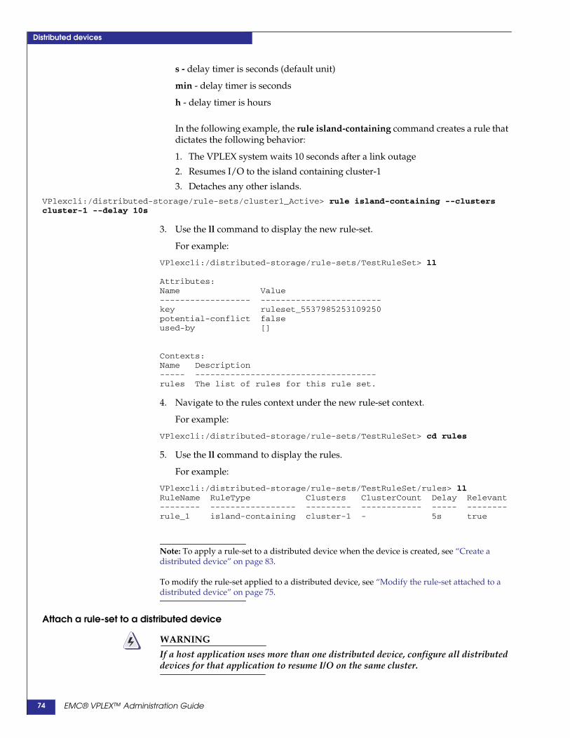
Distributed devices
s - delay timer is seconds (default unit)
min - delay timer is seconds
h - delay timer is hours
In the following example, the rule island-containing command creates a rule thatdictates the following behavior:
1. The VPLEX system waits 10 seconds after a link outage
2. Resumes I/O to the island containing cluster-1
3. Detaches any other islands.
VPlexcli:/distributed-storage/rule-sets/cluster1_Active> rule island-containing --clusterscluster-1 --delay 10s
3. Use the ll command to display the new rule-set.
For example:
VPlexcli:/distributed-storage/rule-sets/TestRuleSet> ll
Attributes:Name Value------------------ ------------------------key ruleset_5537985253109250potential-conflict falseused-by []
Contexts:Name Description----- ------------------------------------rules The list of rules for this rule set.
4. Navigate to the rules context under the new rule-set context.
For example:
VPlexcli:/distributed-storage/rule-sets/TestRuleSet> cd rules
5. Use the ll command to display the rules.
For example:
VPlexcli:/distributed-storage/rule-sets/TestRuleSet/rules> llRuleName RuleType Clusters ClusterCount Delay Relevant-------- ----------------- --------- ------------ ----- --------rule_1 island-containing cluster-1 - 5s true
Note: To apply a rule-set to a distributed device when the device is created, see “Create adistributed device” on page 83.
To modify the rule-set applied to a distributed device, see “Modify the rule-set attached to adistributed device” on page 75.
Attach a rule-set to a distributed device
WARNING
If a host application uses more than one distributed device, configure all distributeddevices for that application to resume I/O on the same cluster.
EMC® VPLEX™ Administration Guide74
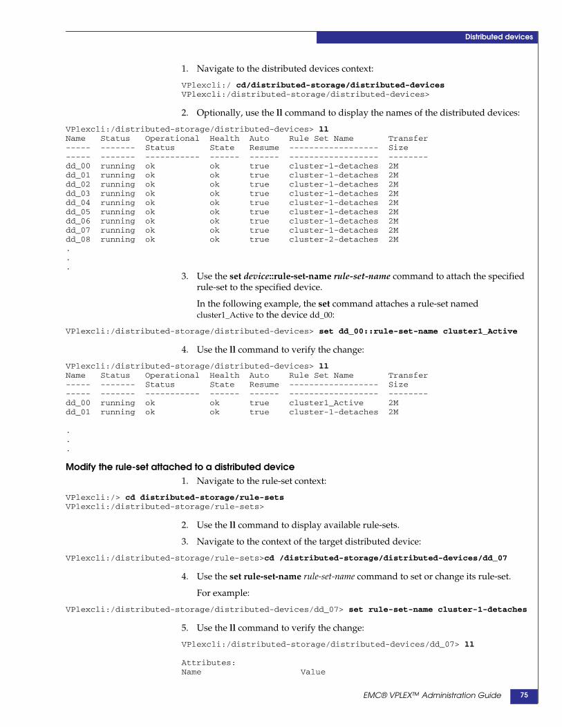
Distributed devices
1. Navigate to the distributed devices context:
VPlexcli:/ cd/distributed-storage/distributed-devicesVPlexcli:/distributed-storage/distributed-devices>
2. Optionally, use the ll command to display the names of the distributed devices:
VPlexcli:/distributed-storage/distributed-devices> llName Status Operational Health Auto Rule Set Name Transfer----- ------- Status State Resume ------------------ Size----- ------- ----------- ------ ------ ------------------ --------dd_00 running ok ok true cluster-1-detaches 2Mdd_01 running ok ok true cluster-1-detaches 2Mdd_02 running ok ok true cluster-1-detaches 2Mdd_03 running ok ok true cluster-1-detaches 2Mdd_04 running ok ok true cluster-1-detaches 2Mdd_05 running ok ok true cluster-1-detaches 2Mdd_06 running ok ok true cluster-1-detaches 2Mdd_07 running ok ok true cluster-1-detaches 2Mdd_08 running ok ok true cluster-2-detaches 2M...
3. Use the set device::rule-set-name rule-set-name command to attach the specifiedrule-set to the specified device.
In the following example, the set command attaches a rule-set namedcluster1_Active to the device dd_00:
VPlexcli:/distributed-storage/distributed-devices> set dd_00::rule-set-name cluster1_Active
4. Use the ll command to verify the change:
VPlexcli:/distributed-storage/distributed-devices> llName Status Operational Health Auto Rule Set Name Transfer----- ------- Status State Resume ------------------ Size----- ------- ----------- ------ ------ ------------------ --------dd_00 running ok ok true cluster1_Active 2Mdd_01 running ok ok true cluster-1-detaches 2M
.
.
.
Modify the rule-set attached to a distributed device1. Navigate to the rule-set context:
VPlexcli:/> cd distributed-storage/rule-setsVPlexcli:/distributed-storage/rule-sets>
2. Use the ll command to display available rule-sets.
3. Navigate to the context of the target distributed device:
VPlexcli:/distributed-storage/rule-sets>cd /distributed-storage/distributed-devices/dd_07
4. Use the set rule-set-name rule-set-name command to set or change its rule-set.
For example:
VPlexcli:/distributed-storage/distributed-devices/dd_07> set rule-set-name cluster-1-detaches
5. Use the ll command to verify the change:
VPlexcli:/distributed-storage/distributed-devices/dd_07> ll
Attributes:Name Value
EMC® VPLEX™ Administration Guide 75
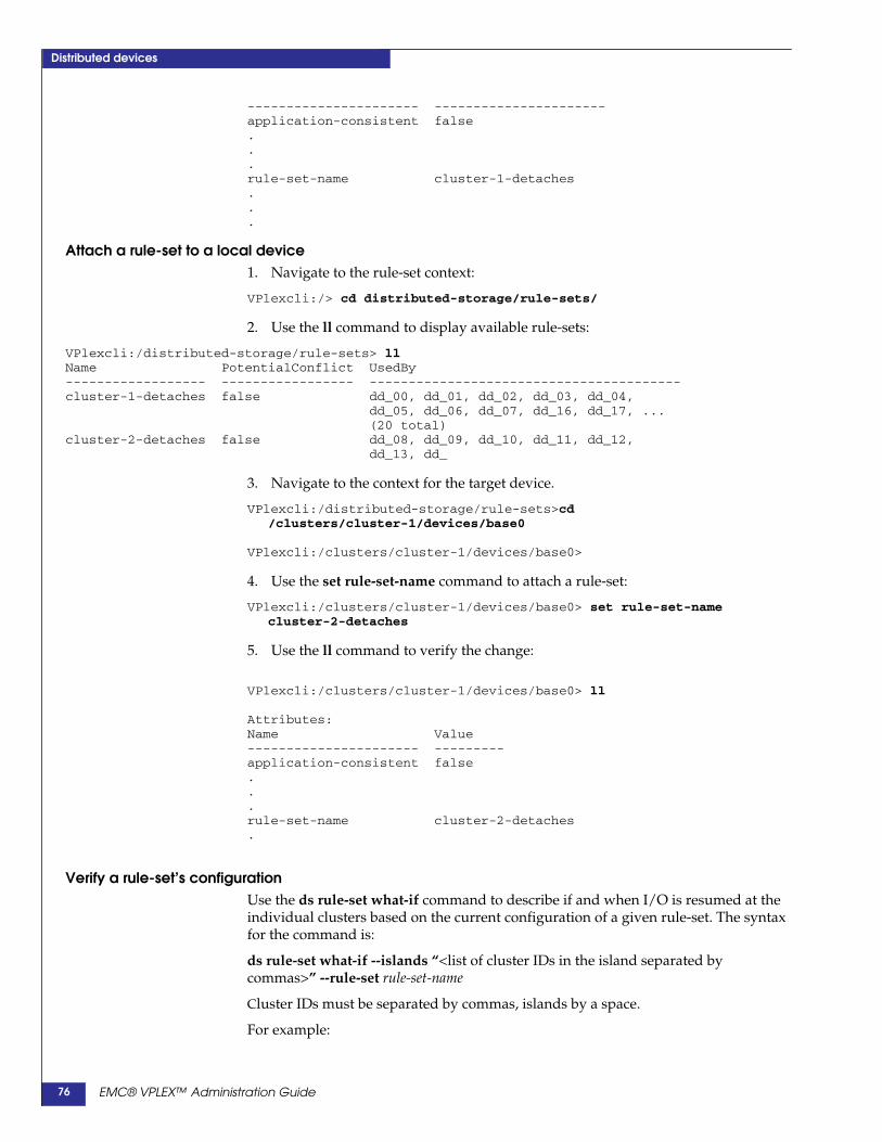
Distributed devices
---------------------- ----------------------application-consistent false...rule-set-name cluster-1-detaches...
Attach a rule-set to a local device1. Navigate to the rule-set context:
VPlexcli:/> cd distributed-storage/rule-sets/
2. Use the ll command to display available rule-sets:
VPlexcli:/distributed-storage/rule-sets> llName PotentialConflict UsedBy------------------ ----------------- ----------------------------------------cluster-1-detaches false dd_00, dd_01, dd_02, dd_03, dd_04,
dd_05, dd_06, dd_07, dd_16, dd_17, ...(20 total)
cluster-2-detaches false dd_08, dd_09, dd_10, dd_11, dd_12,dd_13, dd_
3. Navigate to the context for the target device.
VPlexcli:/distributed-storage/rule-sets>cd/clusters/cluster-1/devices/base0
VPlexcli:/clusters/cluster-1/devices/base0>
4. Use the set rule-set-name command to attach a rule-set:
VPlexcli:/clusters/cluster-1/devices/base0> set rule-set-namecluster-2-detaches
5. Use the ll command to verify the change:
VPlexcli:/clusters/cluster-1/devices/base0> ll
Attributes:Name Value---------------------- ---------application-consistent false...rule-set-name cluster-2-detaches.
Verify a rule-set’s configurationUse the ds rule-set what-if command to describe if and when I/O is resumed at theindividual clusters based on the current configuration of a given rule-set. The syntaxfor the command is:
ds rule-set what-if --islands “<list of cluster IDs in the island separated bycommas>” --rule-set rule-set-name
Cluster IDs must be separated by commas, islands by a space.
For example:
EMC® VPLEX™ Administration Guide76
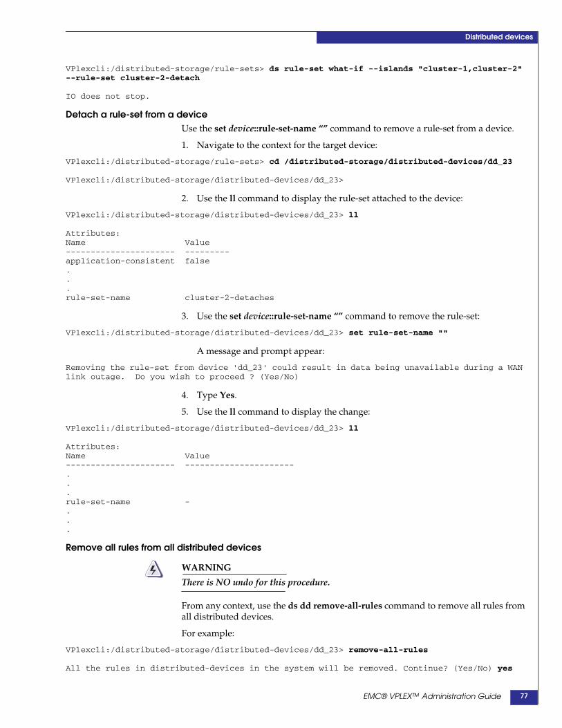
Distributed devices
VPlexcli:/distributed-storage/rule-sets> ds rule-set what-if --islands "cluster-1,cluster-2"--rule-set cluster-2-detach
IO does not stop.
Detach a rule-set from a deviceUse the set device::rule-set-name “” command to remove a rule-set from a device.
1. Navigate to the context for the target device:
VPlexcli:/distributed-storage/rule-sets> cd /distributed-storage/distributed-devices/dd_23
VPlexcli:/distributed-storage/distributed-devices/dd_23>
2. Use the ll command to display the rule-set attached to the device:
VPlexcli:/distributed-storage/distributed-devices/dd_23> ll
Attributes:Name Value---------------------- ---------application-consistent false...rule-set-name cluster-2-detaches
3. Use the set device::rule-set-name “” command to remove the rule-set:
VPlexcli:/distributed-storage/distributed-devices/dd_23> set rule-set-name ""
A message and prompt appear:
Removing the rule-set from device 'dd_23' could result in data being unavailable during a WANlink outage. Do you wish to proceed ? (Yes/No)
4. Type Yes.
5. Use the ll command to display the change:
VPlexcli:/distributed-storage/distributed-devices/dd_23> ll
Attributes:Name Value---------------------- ----------------------...rule-set-name -...
Remove all rules from all distributed devices
WARNING
There is NO undo for this procedure.
From any context, use the ds dd remove-all-rules command to remove all rules fromall distributed devices.
For example:
VPlexcli:/distributed-storage/distributed-devices/dd_23> remove-all-rules
All the rules in distributed-devices in the system will be removed. Continue? (Yes/No) yes
EMC® VPLEX™ Administration Guide 77
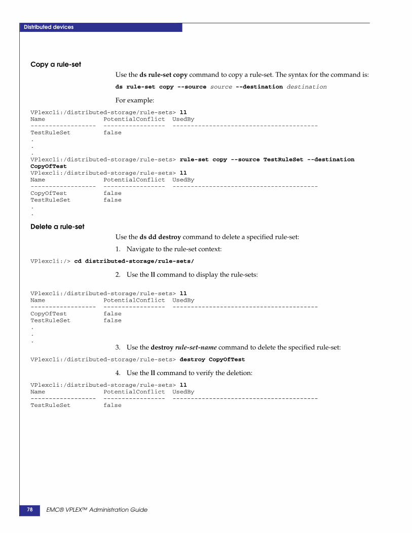
Distributed devices
Copy a rule-setUse the ds rule-set copy command to copy a rule-set. The syntax for the command is:
ds rule-set copy --source source --destination destination
For example:
VPlexcli:/distributed-storage/rule-sets> llName PotentialConflict UsedBy------------------ ----------------- ----------------------------------------TestRuleSet false...VPlexcli:/distributed-storage/rule-sets> rule-set copy --source TestRuleSet --destinationCopyOfTestVPlexcli:/distributed-storage/rule-sets> llName PotentialConflict UsedBy------------------ ----------------- ----------------------------------------CopyOfTest falseTestRuleSet false..
Delete a rule-setUse the ds dd destroy command to delete a specified rule-set:
1. Navigate to the rule-set context:
VPlexcli:/> cd distributed-storage/rule-sets/
2. Use the ll command to display the rule-sets:
VPlexcli:/distributed-storage/rule-sets> llName PotentialConflict UsedBy------------------ ----------------- ----------------------------------------CopyOfTest falseTestRuleSet false...
3. Use the destroy rule-set-name command to delete the specified rule-set:
VPlexcli:/distributed-storage/rule-sets> destroy CopyOfTest
4. Use the ll command to verify the deletion:
VPlexcli:/distributed-storage/rule-sets> llName PotentialConflict UsedBy------------------ ----------------- ----------------------------------------TestRuleSet false
EMC® VPLEX™ Administration Guide78
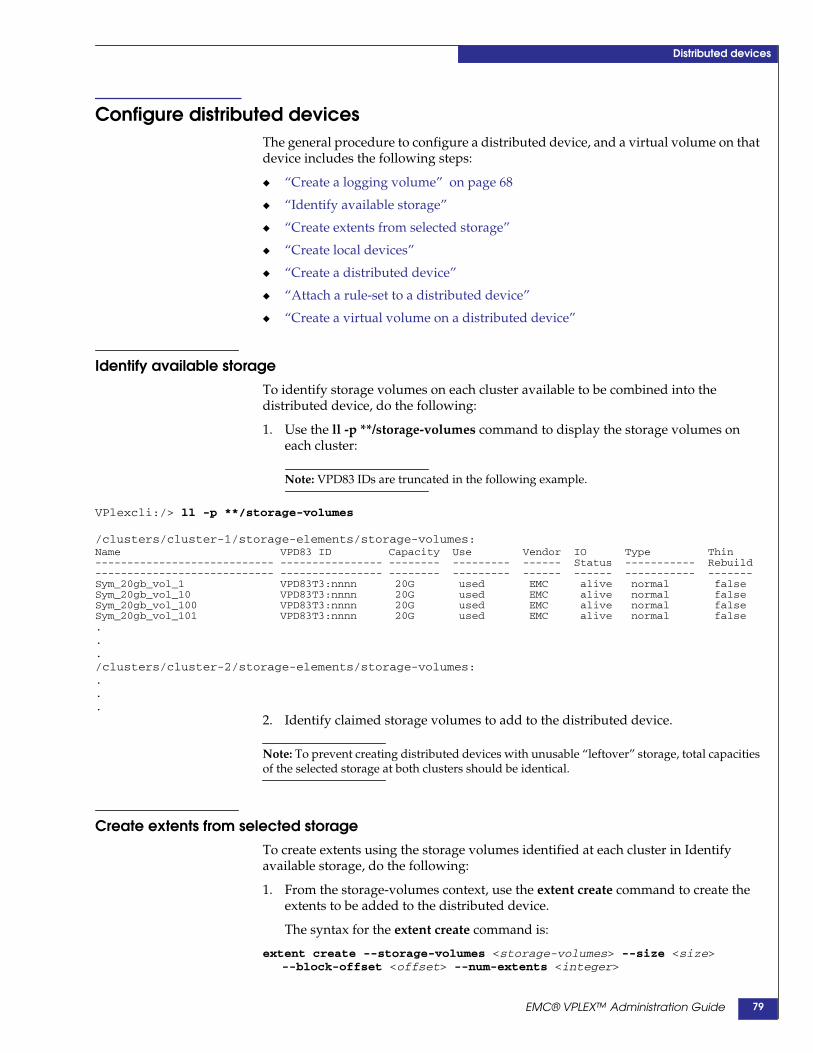
Distributed devices
Configure distributed devicesThe general procedure to configure a distributed device, and a virtual volume on thatdevice includes the following steps:
◆ “Create a logging volume” on page 68
◆ “Identify available storage”
◆ “Create extents from selected storage”
◆ “Create local devices”
◆ “Create a distributed device”
◆ “Attach a rule-set to a distributed device”
◆ “Create a virtual volume on a distributed device”
Identify available storageTo identify storage volumes on each cluster available to be combined into thedistributed device, do the following:
1. Use the ll -p **/storage-volumes command to display the storage volumes oneach cluster:
Note: VPD83 IDs are truncated in the following example.
VPlexcli:/> ll -p **/storage-volumes
/clusters/cluster-1/storage-elements/storage-volumes:Name VPD83 ID Capacity Use Vendor IO Type Thin---------------------------- ---------------- -------- --------- ------ Status ----------- Rebuild---------------------------- ---------------- -------- --------- ------ ------ ----------- -------Sym_20gb_vol_1 VPD83T3:nnnn 20G used EMC alive normal falseSym_20gb_vol_10 VPD83T3:nnnn 20G used EMC alive normal falseSym_20gb_vol_100 VPD83T3:nnnn 20G used EMC alive normal falseSym_20gb_vol_101 VPD83T3:nnnn 20G used EMC alive normal false.../clusters/cluster-2/storage-elements/storage-volumes:...
2. Identify claimed storage volumes to add to the distributed device.
Note: To prevent creating distributed devices with unusable “leftover” storage, total capacitiesof the selected storage at both clusters should be identical.
Create extents from selected storageTo create extents using the storage volumes identified at each cluster in Identifyavailable storage, do the following:
1. From the storage-volumes context, use the extent create command to create theextents to be added to the distributed device.
The syntax for the extent create command is:
extent create --storage-volumes <storage-volumes> --size <size>--block-offset <offset> --num-extents <integer>
EMC® VPLEX™ Administration Guide 79

Distributed devices
--storage-volumes - List of claimed storage volumes to be added to the extent.
--size - Size of each extent. If no size is specified, the largest contiguous range ofblocks is used to create the specified number of extents.
--block-offset - The block offset on the underlying storage volume. If no blockoffset is specified, it is set automatically.
--num-extents - Number of extents to create per specified storage-volume. If nonumber is specified, it creates one extent per storage-volume.
In the following example, two 16 GB storage volumes are used to create an extenton cluster-1:
VPlexcli:/clusters/cluster-1/storage-elements/storage-volumes> extent createVPD83T3:60000970000192601852533030414143,VPD83T3:600009700001926 01852533030414230
2. Navigate to the storage-volumes context on the second cluster and repeat step 1to create one or more extents to be added to the distributed device:
VPlexcli:/clusters/cluster-1/storage-elements/storage-volumes> cd /clusters/cluster-2/storage-elements/storage-volumes/
VPlexcli:/clusters/cluster-2/storage-elements/storage-volumes> extent createVPD83T3:60000970000192601852533030424238,VPD83T3:600009700001926 01852533030424243
3. Navigate to the storage-volume context for each of the extented storage volumes.
4. Use the ll command to display the amount of free space and the largest freechunk size:
VPlexcli:/> cd clusters/cluster-1/storage-elements/storage-volumes/VPD83T3:60000970000192601852533030414234VPlexcli:/clusters/cluster-1/storage-elements/storage-volumes/VPD83T3:60000970000192601852533030414234> llName Value---------------------- -------------------------------------------------------application-consistent falseblock-count 4195200block-size 4Kcapacity 16Gdescription -free-chunks []health-indications []health-state okio-status aliveitls 0x5000144240014720/0x50000972081cf15d/64,
0x5000144240014720/0x50000972081cf165/64,0x5000144240014730/0x50000972081cf165/64,0x5000144240014722/0x50000972081cf158/64,0x5000144240014732/0x50000972081cf158/64,0x5000144240014730/0x50000972081cf15d/64,0x5000144240014732/0x50000972081cf160/64,0x5000144240014722/0x50000972081cf160/64
largest-free-chunk 0Blocality -operational-status okstorage-array-name EMC-SYMMETRIX-192601707storage-volumetype normalsystem-id VPD83T3:60000970000192601852533030414234thin-rebuild falsetotal-free-space 0Buse usedused-by [extent_Symm1852_AB4_1]vendor-specific-name EMC
EMC® VPLEX™ Administration Guide80

Distributed devices
Create local devicesTo create a local device from extents, do the following:
1. Use the ll - p **/extents/ command to display the extents created on each clusterin “Create extents from selected storage” on page 79:
VPlexcli:/> ll -p **/extents/
/clusters/cluster-1/storage-elements/extents:Name StorageVolume Capacity Use--------------------- ------------- -------- -------extent_CX4_Logging_1 CX4_Logging 80G claimedextent_CX4_lun0_1 CX4_lun0 1G usedextent_CX4_lun0_2 CX4_lun0 1G used...extent_Symm1852_21C_1 Symm1852_21C 16G usedextent_Symm1852_AB4_1 Symm1852_AB4 16G claimedextent_Symm1852_AB8_1 Symm1852_AB8 16G claimed
/clusters/cluster-2/storage-elements/extents:Name StorageVolume Capacity Use----------------------------------- -------------------------- -------- -------extent_CX4_Logging_2_1 CX4_Logging_2 80G claimedextent_CX4_Test_Lun_5_1 CX4_Test_Lun_5 10G claimedextent_CX4_Test_Lun_6_1 CX4_Test_Lun_6 10G claimedextent_CX4_Test_Lun_9_1 CX4_Test_Lun_9 10G claimedextent_Cluster_2_VMware_Datastore_1 Cluster_2_VMware_Datastore 200G claimed...
2. Use the local-device create command to create a local device with the specifiedname.
The syntax for the local-device create command is:
local-device create --name name --geometry geometry --extentsextents --stripe-depth depth
--name - Name for the new device. Must be unique across all clusters. Devices ondifferent clusters that have the same name cannot be combined into a distributeddevice.
--geometry - Geometry for the new device. Valid values are “raid-0”, “raid-1”, or“raid-c”.
--extents - List of pathnames of claimed extents to be added to the device,separated by commas. Can also be other local devices (to create a device ofdevices).
--stripe-depth - Required for devices with a geometry of raid-0. Specifies thestripe depth in 4 K byte blocks. The resulting stripe is sized using the followingformula:
<stripe-depth> * <the block size on the source storage extents>
In the following example, the ll command displays the available (claimed)extents, and the local-device create command is used to create a 16 GB RAID 1device on cluster-1:
VPlexcli:/clusters/cluster-1/storage-elements/extents> llName StorageVolume Capacity Use--------------------- ------------- -------- -------
EMC® VPLEX™ Administration Guide 81

Distributed devices
.
.
.extent_Symm1852_AAC_1 Symm1852_AAC 16G claimedextent_Symm1852_AB0_1 Symm1852_AB0 16G claimedextent_Symm1852_AB4_1 Symm1852_AB4 16G claimedextent_Symm1852_AB8_1 Symm1852_AB8 16G claimed
VPlexcli:/clusters/cluster-1/storage-elements/extents> local-device create --nameTestDevCluster1 --geometry raid-1 --extents /clusters/cluster-1/storage-elements/extents/extent_Symm1852_AAC_1,/clusters/cluster-1/storage-elements/extents/extent_Symm1852_AB0_1
3. Navigate to the extents context on the second cluster:
VPlexcli:/clusters/cluster-1/storage-elements/extents> cd /clusters/cluster-2/storage-elements/extents/
4. Use the local-device create command to create a local device with the samecapacity.
In the following example, the ll command displays the available (claimed)extents, and the local-device create command is used to create a 16 GB RAID 1device on cluster-2:
VPlexcli:/clusters/cluster-2/storage-elements/extents> llName StorageVolume Capacity Use----------------------------------- -------------------------- -------- -------...extent_Symm1852_BB8_1 Symm1852_BB8 16G claimedextent_Symm1852_BBC_1 Symm1852_BBC 16G claimedextent_base_volume_1 base_volume 2G usedextent_base_volume_2 base_volume 2G used
VPlexcli:/clusters/cluster-2/storage-elements/extents> local-device create --nameTestDevCluster2 --geometry raid-c --extents /clusters/cluster-2/storage-elements/extents/extent_Symm1852_BB8_1,/clusters/cluster-2/storage-elements/extents/extent_Symm1852_BBC_1
5. Return to the root context and use the ll **/devices/ command to display the newdevices on both clusters:
VPlexcli:/clusters/cluster-2/storage-elements/extents> cdVPlexcli:/> ll -p **/devices
/clusters/cluster-1/devices:Name Operational Health Block Block Capacity Geometry Visibility Transfer Virtual--------------- Status State Count Size -------- -------- ---------- Size Volume--------------- ----------- ------ ------- ----- -------- -------- ---------- -------- ---------TestDevCluster1 ok ok 4195200 4K 16G raid-1 local 2M -base0 ok ok 262144 4K 1G raid-0 local - base0_volbase1 ok ok 262144 4K 1G raid-0 local - base1_volbase2 ok ok 262144 4K 1G raid-0 local - base2_volbase3 ok ok 262144 4K 1G raid-0 local - base3_vol
/clusters/cluster-2/devices:Name Operational Health Block Block Capacity Geometry Visibility Transfer Virtual--------------- Status State Count Size -------- -------- ---------- Size Volume--------------- ----------- ------ ------- ----- -------- -------- ---------- -------- ----------TestDevCluster2 ok ok 8390400 4K 32G raid-c local - -
EMC® VPLEX™ Administration Guide82

Distributed devices
base01 ok ok 524288 4K 2G raid-0 local - base01_volbase02 ok ok 524288 4K 2G raid-0 local - base02_volbase03 ok ok 524288 4K 2G raid-0 local - base03_vol
Create a distributed deviceLocal devices on each cluster constitute the two “legs” of the distributed device. Theindividual local devices may include any underlying type of storage volume orgeometry (RAID 0, RAID 1, or RAID C), but they should be the same capacity.
If a distributed device is configured with local devices of different capacities:
◆ The resulting distributed device will be only as large as the smaller local device.
◆ The “leftover” capacity on the larger device will not be available.
To create a distributed device without wasting capacity, choose local devices on eachcluster with the same capacity.
CAUTION!If there is pre-existing data on a storage-volume, and the storage-volume is notclaimed as being application-specific, converting an existing local RAID device toa distributed RAID will NOT initiate a rebuild to copy the data to the other leg.Data will exist at only one cluster.
To prevent this, do one of the following:
1) Claim the disk with data using the application-consistent flag, or
2) Create a single-legged RAID 1 or RAID 0 and add a leg using the deviceattach-mirror command.
To create a distributed device from two local devices with the same capacity:
1. Use the ll --p ** /devices command to display the available (no virtual volumeconfigured) local devices.
VPlexcli:/> ll -p **/devices
/clusters/cluster-1/devices:Name Operational Health Block Block Capacity Geometry Visibility Transfer Virtual--------------- Status State Count Size -------- -------- ---------- Size Volume--------------- ----------- ------ ------- ----- -------- -------- ---------- -------- ---------TestDevCluster1 ok ok 4195200 4K 16G raid-1 local 2M -base0 ok ok 262144 4K 1G raid-0 local - base0_volbase1 ok ok 262144 4K 1G raid-0 local - base1_volbase2 ok ok 262144 4K 1G raid-0 local - base2_volbase3 ok ok 262144 4K 1G raid-0 local - base3_vol
/clusters/cluster-2/devices:Name Operational Health Block Block Capacity Geometry Visibility Transfer Virtual--------------- Status State Count Size -------- -------- ---------- Size Volume--------------- ----------- ------ ------- ----- -------- -------- ---------- -------- ----------TestDevCluster2 ok ok 4195200 4K 16G raid-1 local 2M -base01 ok ok 524288 4K 2G raid-0 local - base01_volbase02 ok ok 524288 4K 2G raid-0 local - base02_volbase03 ok ok 524288 4K 2G raid-0 local - base03_vol
2. Use the ds dd create command to create a distributed device.
The syntax for the command is:
EMC® VPLEX™ Administration Guide 83

Distributed devices
ds dd create --name name --devices devices --logging-volumelogging-volumes --rule-set rule-set
--name <name> - The name must be unique across the entire VPLEXconfiguration.
-- devices - List of pathnames to local devices to add to the distributed device.Select devices that have the same capacities. Separate entries in the list bycommas.
--logging-volume - List of pathnames to one or more logging volumes to use withthe new device.
If no logging volume is specified, a logging volume is automatically selected fromany available logging volume that has sufficient space for the required entries. Ifno available logging volume exists, an error message is returned. See“Loggingvolumes” on page 67.
--rule-set - Attaches the specified rule-set to the device. If no rule-set is specified,the cluster that is local to the management server is assumed to be the winner inthe event of an inter-cluster link outage. See “Manage rule-sets” on page 73.
In the following example, the ds dd create command creates a distributed device,and the default rule-set behavior is applied to the new device:
VPlexcli:/> ds dd create --name TestDevice --devices/clusters/cluster-1/devices/TestDevCluster1,/clusters/cluster-2/devices/TestDevCluster2
Distributed-device 'TestDisDevice' is using rule-set 'cluster-2-detaches'.
3. Use the ll **/new device name command to display the new distributed device:
VPlexcli:/> ll **/TestDisDevice
/distributed-storage/distributed-devices/TestDevice:
Attributes:Name Value---------------------- ----------------------application-consistent falseauto-resume -block-count 4195200block-size 4Kcapacity 16Gclusters-involved [cluster-1, cluster-2]geometry raid-1...
EMC® VPLEX™ Administration Guide84
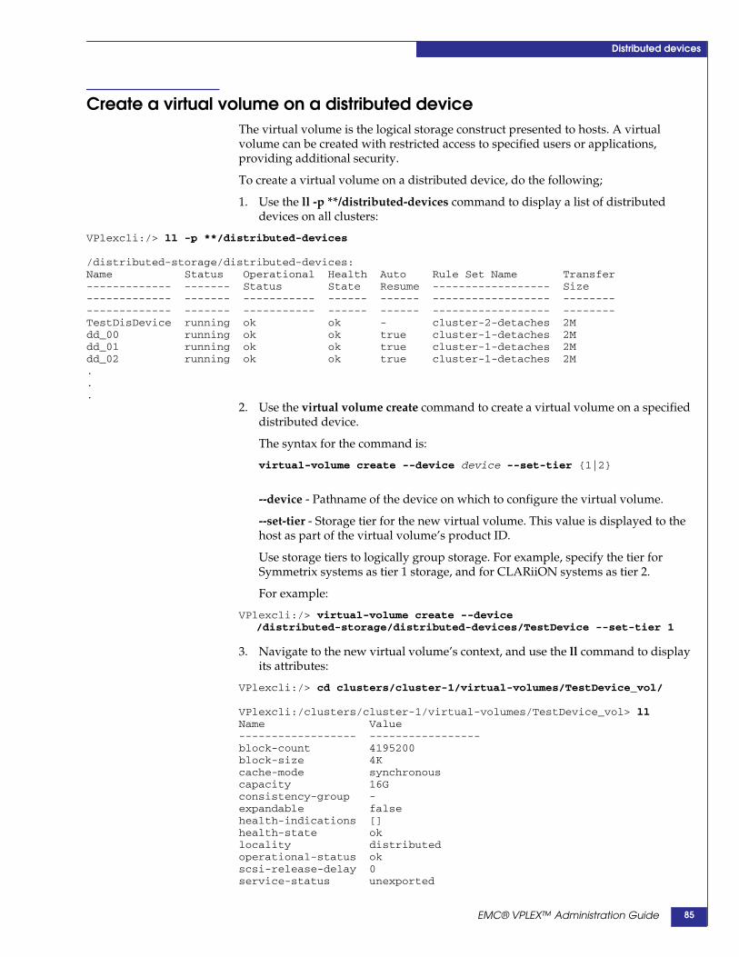
Distributed devices
Create a virtual volume on a distributed deviceThe virtual volume is the logical storage construct presented to hosts. A virtualvolume can be created with restricted access to specified users or applications,providing additional security.
To create a virtual volume on a distributed device, do the following;
1. Use the ll -p **/distributed-devices command to display a list of distributeddevices on all clusters:
VPlexcli:/> ll -p **/distributed-devices
/distributed-storage/distributed-devices:Name Status Operational Health Auto Rule Set Name Transfer------------- ------- Status State Resume ------------------ Size------------- ------- ----------- ------ ------ ------------------ --------------------- ------- ----------- ------ ------ ------------------ --------TestDisDevice running ok ok - cluster-2-detaches 2Mdd_00 running ok ok true cluster-1-detaches 2Mdd_01 running ok ok true cluster-1-detaches 2Mdd_02 running ok ok true cluster-1-detaches 2M...
2. Use the virtual volume create command to create a virtual volume on a specifieddistributed device.
The syntax for the command is:
virtual-volume create --device device --set-tier {1|2}
--device - Pathname of the device on which to configure the virtual volume.
--set-tier - Storage tier for the new virtual volume. This value is displayed to thehost as part of the virtual volume’s product ID.
Use storage tiers to logically group storage. For example, specify the tier forSymmetrix systems as tier 1 storage, and for CLARiiON systems as tier 2.
For example:
VPlexcli:/> virtual-volume create --device/distributed-storage/distributed-devices/TestDevice --set-tier 1
3. Navigate to the new virtual volume’s context, and use the ll command to displayits attributes:
VPlexcli:/> cd clusters/cluster-1/virtual-volumes/TestDevice_vol/
VPlexcli:/clusters/cluster-1/virtual-volumes/TestDevice_vol> llName Value------------------ -----------------block-count 4195200block-size 4Kcache-mode synchronouscapacity 16Gconsistency-group -expandable falsehealth-indications []health-state oklocality distributedoperational-status okscsi-release-delay 0service-status unexported
EMC® VPLEX™ Administration Guide 85
Distributed devices
storage-tier 1supporting-device TestDevicesystem-id TestDevice_volvolume-type virtual-volume
Note: Virtual volume names are assigned automatically based on the device name and asequential virtual volumes number.
EMC® VPLEX™ Administration Guide86
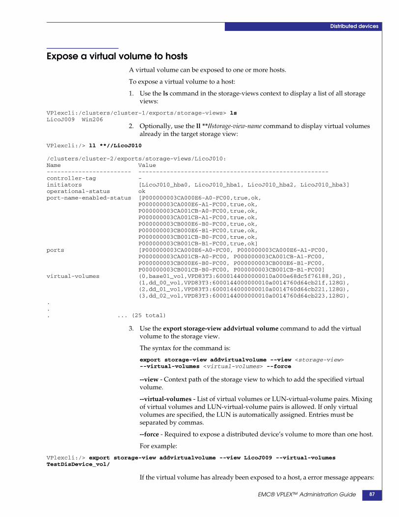
Distributed devices
Expose a virtual volume to hostsA virtual volume can be exposed to one or more hosts.
To expose a virtual volume to a host:
1. Use the ls command in the storage-views context to display a list of all storageviews:
VPlexcli:/clusters/cluster-1/exports/storage-views> lsLicoJ009 Win206
2. Optionally, use the ll **//storage-view-name command to display virtual volumesalready in the target storage view:
VPlexcli:/> ll **//LicoJ010
/clusters/cluster-2/exports/storage-views/LicoJ010:Name Value------------------------ ------------------------------------------------------controller-tag -initiators [LicoJ010_hba0, LicoJ010_hba1, LicoJ010_hba2, LicoJ010_hba3]operational-status okport-name-enabled-status [P000000003CA000E6-A0-FC00,true,ok,
P000000003CA000E6-A1-FC00,true,ok,P000000003CA001CB-A0-FC00,true,ok,P000000003CA001CB-A1-FC00,true,ok,P000000003CB000E6-B0-FC00,true,ok,P000000003CB000E6-B1-FC00,true,ok,P000000003CB001CB-B0-FC00,true,ok,P000000003CB001CB-B1-FC00,true,ok]
ports [P000000003CA000E6-A0-FC00, P000000003CA000E6-A1-FC00,P000000003CA001CB-A0-FC00, P000000003CA001CB-A1-FC00,P000000003CB000E6-B0-FC00, P000000003CB000E6-B1-FC00,P000000003CB001CB-B0-FC00, P000000003CB001CB-B1-FC00]
virtual-volumes (0,base01_vol,VPD83T3:6000144000000010a000e68dc5f76188,2G),(1,dd_00_vol,VPD83T3:6000144000000010a0014760d64cb21f,128G),(2,dd_01_vol,VPD83T3:6000144000000010a0014760d64cb221,128G),(3,dd_02_vol,VPD83T3:6000144000000010a0014760d64cb223,128G),
.
.
. ... (25 total)
3. Use the export storage-view addvirtual volume command to add the virtualvolume to the storage view.
The syntax for the command is:
export storage-view addvirtualvolume --view <storage-view>--virtual-volumes <virtual-volumes> --force
--view - Context path of the storage view to which to add the specified virtualvolume.
--virtual-volumes - List of virtual volumes or LUN-virtual-volume pairs. Mixingof virtual volumes and LUN-virtual-volume pairs is allowed. If only virtualvolumes are specified, the LUN is automatically assigned. Entries must beseparated by commas.
--force - Required to expose a distributed device’s volume to more than one host.
For example:
VPlexcli:/> export storage-view addvirtualvolume --view LicoJ009 --virtual-volumesTestDisDevice_vol/
If the virtual volume has already been exposed to a host, a error message appears:
EMC® VPLEX™ Administration Guide 87

Distributed devices
VPlexcli:/> export storage-view addvirtualvolume -view lsca5230view --virtual-volumeExchangeDD_vol --force
WARNING: Volume 'ExchangeDD_vol' is already assigned to view 'lsca3207view'
4. Re-scan the disks on each host to ensure that each host can access the virtualvolume.
EMC® VPLEX™ Administration Guide88
Distributed devices
Expose a virtual volume to a remote hostTo enable a host to access a virtual volume on a remote cluster, expose the virtualvolume on one cluster to a host on a different cluster.
To expose a virtual volume to a remote host:
1. Navigate to the device context of the target device:
VPlexcli:/> cd clusters/cluster-1/devices/base0
2. Use the set visibility global command to set the device’s visibility to global:
VPlexcli:/clusters/cluster-1/devices/base0> set visibility global
3. Optionally, use the ll command to verify that change:
VPlexcli:/clusters/cluster-1/devices/base0> ll
Attributes:Name Value---------------------- ---------application-consistent false...transfer-size -virtual-volume base0_volvisibility global...4. Use the export storage-view addvirtualvolume command to expose the virtual
volume to the remote host.
For example:
VPlexcli:/clusters/cluster-1//devices/base0> export storage-view addvirtualvolume --viewE_209_view --virtual-volumes Symm1254_7BF_1_vol
5. Re-scan the disks on each host to ensure that each host can access the virtualvolume.
Note: When a local-device is exported, it is automatically assigned the rule-set for its enclosingcluster.
EMC® VPLEX™ Administration Guide 89
Distributed devices
Add a local mirror to distributed deviceAttach a mirror to the local leg of a distributed device to increase data protection.
Use the device attach-mirror command to attach a local mirror to a distributeddevice.
In the following example, the distributed device TestDevDevice is composed of:
◆ TestDevCluster1 (device on cluster-1)
◆ TestDevCluster2 (device on cluster-2)
To add a local mirror to a component device of a distributed device:
1. Navigate to the cluster-n context on the cluster where the mirror will be added:
VPlexcli:/> cd clusters/cluster-1/
2. Use the ll **/extents command to display a list of extents:
VPlexcli:/clusters/cluster-1> ll **/extents
/clusters/cluster-1/storage-elements/extents:Name StorageVolume Capacity Use--------------------- ------------- -------- -------extent_CX4_Logging_1 CX4_Logging 80G claimedextent_CX4_lun0_1 CX4_lun0 1G usedextent_CX4_lun0_2 CX4_lun0 1G usedextent_CX4_lun0_3 CX4_lun0 1G usedextent_CX4_lun0_4 CX4_lun0 1G usedextent_CX4_lun0_5 CX4_lun0 1G claimedextent_CX4_lun0_6 CX4_lun0 1G claimed
3. Identify one or more claimed extents whose combined capacity matches thedistributed device.
4. Use the local-device create command to create a device of the same capacity asthe distributed device.
For example:
VPlexcli:/clusters/cluster-1> local-device create --name TestDevCluster1mirror --geometryraid-0 --extents extent_Symm1254_7BC_2, extent_Symm1254_7BE_2
5. Use the device attach-mirror command to attach the new device to the local(same cluster as the current context) leg of the distributed device. The syntax forthe command is:
device attach-mirror --device <device> --mirror <mirror> --rule-set<rule-set> --force
-- device - Name or context path of the device to add the mirror to. The targetdevice must not have a virtual volume configured. If the name of a device is used,verify that the same device name is not used by any local-device in a differentcluster.
--mirror - Name or context path of the device to add as a mirror. It must be atop-level device. Verify that the same device name is not used by any local-devicein a different cluster.
--force - Forces a rule-set with a potential conflict to be applied.
--rule-set - The rule-set applied to the device.
If the --rule-set option is omitted, a default rule-set is assigned as follows:
EMC® VPLEX™ Administration Guide90
Distributed devices
• If the parent device has a volume, the device inherits the rule-set of the parent.
• If the parent device does not have a volume, the cluster that is local to themanagement server is the winner.
Note: The VPLEX system displays a message indicating which rule-set has been assigned.
For example:
VPlexcli:/clusters/cluster-2> device attach-mirror --device/clusters/cluster-2/devices/TestDevCluster2 --mirrorTestDevCluster2 Mirror
A rebuild is automatically started to synchronize the mirror.
Note: Use the rebuild status command to monitor the rebuild.
EMC® VPLEX™ Administration Guide 91
Distributed devices
Remove a local mirror from a distributed deviceTo remove the local mirror from a distributed device, do the following:
Use the device detach-mirror command to remove a mirror from a local device. Thesyntax of the command is:
device detach-mirror[-d|--device] [context path|name][-m|--mirror] [context path|name][-s|--slot] slot number[-i|--discard][-f|--force]
[-d|--device] context path or name - * Name or context path of the device from whichto detach the mirror. Does not have to be a top-level device. If the device name isused, verify that the name is unique throughout the VPLEX, including local deviceson other clusters.
[-m|--mirror] context path or name - * Name or context path of the mirror to detach.Does not have to be a top-level device. If the device name is used, verify that thename is unique throughout the VPLEX, including local devices on other clusters.
[-s|--slot] slot number - Optional argument. Slot number of the mirror to bediscarded. Applicable only when the --discard argument is used.
[-i|--discard] - Optional argument. When specified, discards the data in the mirrorthat is to be detached.
[-f|--force] -Force the mirror to be discarded. Must be used when the --discardargument is used.
For example:
VPlexcli:/clusters/cluster-2> device detach-mirror --device/clusters/cluster-2/devices/TestDevCluster2 --mirror /clusters/cluster-2/devices/TestDevCluster2MirrorDetached mirror TestDevCluster2Mirror.Mirror TestDevCluster2Mirror is below /clusters/cluster-2/devices.
The mirror is removed from the cluster, but the distributed device is left intact andfunctional.
EMC® VPLEX™ Administration Guide92
Distributed devices
Create a distributed device from an exported volumeThe device attach-mirror command can be used to create a distributed device using:
◆ A local, exported volume as the source
◆ A device on the remote cluster as the mirror
Adding a mirror using this method expands the local device into a distributed devicewithout impacting host I/O.
To add a remote mirror to an exported volume:
1. Use the local-device create command to create a local device on the remotecluster.
For example:
VPlexcli:/clusters/cluster-2> local-device create --name RemoteMirrorCluster2 --geometryraid-0 --extents extent_Symm1254_7BC_3, extent_Symm1254_7BE_3 --stripe-depth 1
2. Use the device attach-mirror command to attach the local device on the remotecluster to the leg on local cluster used as the basis for the distributed device:
VPlexcli:/clusters/cluster-1/devices> device attach-mirror --device/clusters/cluster-1/devices/SourceVolumeCluster1 --mirror/clusters/cluster-2/devices/RemoteMirrorCluster2
The device on the remote cluster is added as a mirror to the exported volume onthe local cluster.
A rebuild is automatically started to synchronize the two devices.
Note: Use the rebuild status command to monitor the rebuild.
While the rebuild is in progress, I/O on the volume being mirrored continueswithout host access being affected.
EMC® VPLEX™ Administration Guide 93

Distributed devices
Display/enable/disable automatic device rebuildsBy default, automatic device rebuilds are enabled on all devices. For configurationswith limited bandwidth between clusters, it may be useful to disable automaticrebuilds.
Use the set command to enable/disable automatic rebuilds on the distributed device.The rebuild setting is immediately applied to the device.
◆ Set rebuild-allowed to true to start or resume a rebuild if the mirror legs are out ofsync.
◆ Set rebuild-allowed set to false to stop any rebuild in progress.
When automatic rebuild is re-enabled on a device where it has been disabled, therebuild starts again from the place where it stopped.
Display device’s rebuild settingTo display the automatic rebuild setting on a device, navigate to the context of thetarget distributed device:
VPlexcli:/>cd distributed-storage/distributed-devices/TestDevDevice
Use the ll command to display detailed information about the device, including itsrebuild-allowed setting:
VPlexcli:/distributed-storage/distributed-devices/TestDevDevice> ll
Attributes:Name Value---------------------- ----------------------...rebuild-allowed true
Enable automatic rebuildsTo allow automatic rebuilds after a failed inter-cluster link has been restored:
1. Navigate to the to the context of the target distributed device:
VPlexcli:/cd distributed-storage/distributed-devices/TestDevDevice
2. Use the set rebuild-allowed true command to allow automatic rebuilds after afailed inter-cluster link has been restored:
VPlexcli:/distributed-storage/distributed-devices/TestDevDevice> set rebuild-allowed true3. Use the ll command to display the change.
Disable automatic rebuildsTo prevent automatic rebuild after a failed inter-cluster link has been restored:
1. Navigate to the context of the target distributed-device:
VPlexcli:/cd distributed-storage/distributed-devices/TestDisDevice
EMC® VPLEX™ Administration Guide94

Distributed devices
2. Use the set rebuild-allowed false command to prevent automatic rebuilds after afailed inter-cluster link has been restored:
VPlexcli:/distributed-storage/distributed-devices/TestDevDevice> set rebuild-allowed false3. Use the ll command to display the change.
EMC® VPLEX™ Administration Guide 95

Distributed devices
Configure I/O resumption after a network outageThis section describes the procedures to
◆ “Enable/disable I/O auto-resume on a losing cluster” on page 96
◆ “Resume I/O on a losing cluster (auto-resume is false)” on page 96
◆ “Resume I/O on a cluster during link outage” on page 97
◆ “Resume I/O for a conflicting detach” on page 98
By default, the cluster local to the management server used to create a distributeddevice is the “winner” in the event of a network outage.
Rule-sets determine which cluster “wins” when a network outage occurs.
Use the set auto-resume command to determine what happens at the losing clusterafter the link is restored.
Use the device resume-link-up command to manually resume I/O on the losingcluster when the auto-resume flag is false.
Use the device resume-link-down command to manually resume I/O on asuspended volume while the link is down.
Enable/disable I/O auto-resume on a losing clusterUse the set auto-resume true command to configure a distributed device toautomatically resume I/O on the losing cluster after the network outage is restoredbetween clusters.
The syntax of the command is:
set auto-resume {true|false}
For example:
VPlexcli:/cd distributed-storage/distributed-devices/TestDevDeviceVPlexcli:/distributed-storage/distributed-devices/TestDevDevice> set auto-resume trueVPlexcli:/distributed-storage/distributed-devices/TestDevDevice> ll
Attributes:Name Value---------------------- ----------------------application-consistent falseauto-resume true...
Resume I/O on a losing cluster (auto-resume is false)When a distributed device’s auto-resume is set to false, use the deviceresume-link-up command to manually resume I/O to the mirror leg on the losingcluster after the link outage recovers.
Use the device resume-link-up command to resume I/O on:
◆ All suspended virtual volumes of the specified top-level distributed devices
◆ The given distributed virtual volumes,
◆ All the distributed virtual volumes in the system.
EMC® VPLEX™ Administration Guide96
Distributed devices
The syntax of the command is:
device resume-link-up --force {--virtual-volume<virtual-volume>|--devices <devices>|--all}
--virtual-volume - List of context paths to one or more virtual volumes, separated bycommas. Resume I/O on only the specified virtual volume.
--devices - List of context paths to one or more top-level devices, separated bycommas. Resume I/O on only the specified top level device.
--all - Resume I/O on all virtual volumes on the losing clusters.
--force - Forces I/O to resume.
For example:
VPlexcli:/distributed-storage/distributed-devices> deviceresume-link-up --devices DDte_4a –-force
Resume I/O on a cluster during link outage
WARNING
The device resume-link-down command causes I/O to resume on the local clusterregardless of any rule-sets applied to the device. Verify that rules and any manualdetaches do not result in conflicting detaches (cluster-1 detaching cluster-2, andcluster-2 detaching cluster-1). Conflicting detaches will result in lost data on thelosing cluster, a full rebuild, and degraded access during the time of the full rebuild.
Use the device resume-link-down command to resume I/O to the mirror leg ofdistributed devices during a link outage.
CAUTION!Be careful not to introduce a conflicted detach by allowing both legs of distributeddevices to independently resume I/O.
The syntax for the command is:
device resume-link-down {--all-at-island|--cluster <context-path>|--devices<context-path,context-path>} --force
--all-at-island - Resumes I/O on all devices on the chosen winning cluster and theclusters with which it is in communication.
--cluster - Context path to a cluster. Resumes I/O on the specified cluster and theclusters it is in communication with during a link outage. Necessary only when theall-at-island flag or distributed devices are specified. Not required for local deviceswith global visibility.
--devices - List of context paths to one or more top-level devices, separated bycommas. Resumes I/O for the specified devices.
--force - Forces I/O to resume.
For example:
VPlexcli:/distributed-storage/distributed-devices> deviceresume-link-down --all-at-island --cluster --devices DD_5d --force
EMC® VPLEX™ Administration Guide 97

Distributed devices
Resume I/O for a conflicting detachWhen a conflicting detach occurs, use the ds dd declare-winner command tomanually designate the winning cluster.
When the link is restored, the leg on losing cluster is rebuilt from the leg on thewinning cluster.
The syntax for the command is:
ds dd declare-winner --distributed-device <distributed-device>--cluster <cluster> --force
--distributed-device - Specifies the distributed-device for which to declare a winningcluster.
--cluster - Specifies the winning cluster.
--force - Forces the 'declare-winner' command to be issued.
For example:
VPlexcli:/distributed-storage/distributed-devices> ds dddeclare-winner --distributed-device DDtest_4 –-cluster cluster-2
EMC® VPLEX™ Administration Guide98

6
This chapter describes the following topics:
◆ About data migrations.................................................................... 100◆ One time migrations ........................................................................ 100◆ Batch migrations............................................................................... 100◆ Prerequisites for target devices/extents ....................................... 101
◆ About rebuilds................................................................................. 102◆ Performance considerations ........................................................... 103
◆ One-time data migrations.............................................................. 104◆ Start a one-time device or extent data migration ........................ 104◆ Monitor a migration’s progress...................................................... 105◆ Pause/resume a migration (optional) ........................................... 106◆ Cancel a migration (optional)......................................................... 106◆ Commit a completed migration ..................................................... 107◆ Clean a migration ............................................................................. 107◆ Remove migration records.............................................................. 108
◆ Batch migrations.............................................................................. 109◆ Create a batch migration plan ........................................................ 109◆ Check a batch migration plan......................................................... 110◆ Modify a batch migration file ......................................................... 111◆ Start a batch migration .................................................................... 111◆ Pause/resume a batch migration (optional) ................................ 111◆ Cancel a batch migration (optional) .............................................. 112◆ Monitor a batch migration’s progress ........................................... 112◆ View a batch migration’s status ..................................................... 113◆ Commit a batch migration .............................................................. 113◆ Clean a batch migration .................................................................. 114◆ Remove batch migration records ................................................... 115
Data migration
EMC® VPLEX™ Administration Guide 99
Data migration
About data migrationsThere are two types of data migrations:
◆ One time migrations - Begin an extent or device migration immediately when thedm migration start command is used.
◆ Batch migrations - Are run as batch jobs using re-usable migration plan files.Multiple device or extent migrations can be executed using a single command.
One time migrations One time migrations include:
◆ Extent migrations - Extent migrations move data between extents in the samecluster. Use extent migrations to:
• Move extents from a “hot” storage volume shared by other busy extents
• Defragment a storage volume to create more contiguous free space
• Perform migrations where the source and target have the same number ofvolumes with identical capacities
◆ Device migrations - Devices are RAID 0, RAID 1, or RAID C devices built onextents or on other devices.
Device migrations move data between devices on the same cluster or betweendevices on different clusters. Use device migrations to:
• Migrate data between dissimilar arrays
• Relocate a “hot” volume to a faster array
• Relocate devices to new arrays in a different cluster
Note: Device migrations between distributed devices is not supported.
Batch migrations Batch migrations migrate multiple extents or devices. Create batch migrations toautomate routine tasks:
• Use batched extent migrations to migrate arrays within the same cluster wherethe source and destination have the same number of LUNs and identicalcapacities.
• Use batched device migrations to migrate to dissimilar arrays (user mustconfigure the destination’s capacities to match the capacity and tier of thesource array), and to migrate devices between clusters in a VPLEX Metro orVPLEX Geo.
Up to 25 local and 25 distributed migrations can be in progress at the same time. Anymigrations beyond those limits are queued until an existing migration completes.
General procedure to perform data migrationUse the following general steps to perform extent and device migrations:
1. Create and check a migration plan (batch migrations only).
2. Start the migration.
3. Monitor the migration’s progress.
4. Pause, resume, or cancel the migration (optional).
EMC® VPLEX™ Administration Guide100

Data migration
5. Commit the migration. Commit transfers the source virtualvolume/device/extent to the target.
If the virtual volume on top of a device has a system-assigned default name,committing a device migration renames the virtual volume after the target device.
6. Clean up (optional).
For extent migrations: dismantle the source devices or destroy the source extentand unclaim its storage-volume.
7. Remove the record of the migration.
Prerequisites for target devices/extentsThe target device or extent must:
◆ Be the same size or larger than the source device or extent
If the target is larger in size than the source, the extra space cannot be utilized.
For example, if the source is 200 GB, and the target is 500 GB, only 200 GB of thetarget can be used after a migration. The remaining 300 GB cannot be claimed.
◆ Not have any existing volumes on it.
WARNING
Device migrations are not recommended between clusters. All device migrations aresynchronous. If there is I/O to the devices being migrated, and latency to the targetcluster is equal to or greater than 5ms, significant performance degradation mayoccur.
EMC® VPLEX™ Administration Guide 101
Data migration
About rebuildsRebuilds synchronize data from a source drive to a target drive. When differencesarise between legs of a RAID, a rebuild updates the out-of-date leg.
There are two types of rebuild behavior:
◆ A full rebuild copies the entire contents of the source to the target.
◆ A logging rebuild copies only changed blocks from the source to the target.
Local mirrors are updated using a full rebuild (local devices do not use loggingvolumes).
In VPLEX Metro and Geo configurations, all distributed devices have an associatedlogging volume. Logging volumes keep track of blocks written during aninter-cluster link outage. After a link or leg is restored, the VPLEX system uses theinformation in logging volumes to synchronize mirrors by sending only changedblocks across the link.
Logging volume rebuilds also occur when a leg of a disaster recovery RAID 1 (DR1)becomes unreachable, but recovers quickly.
If a logging volume is unavailable at the time that a leg is scheduled to be markedout-of-date (via the log), the leg is marked as fully out-of-date, causing a full rebuild.
The unavailability of a logging volume matters both at the time of recovery (when thesystem reads the logging volume) and at the time that a write failed on one leg andsucceeded on another (when the system begins writes to the logging volume).
CAUTION!If no logging volume is available, an inter-cluster link restoration will cause a fullrebuild of every distributed device to which there were writes while the link wasdown.
See “Logging volumes” on page 67.
Rebuilds for thin provisioned storageThin provisoning allows storage to migrate onto a thinly provisioned storagevolumes while allocating the minimal amount of thin storage pool capacity.
Thinly provisioned storage volumes can be incorporated into RAID 1 mirrors withsimilar consumption of thin storage pool capacity.
VPLEX preserves the unallocated thin pool space of the target storage volume bydetecting zeroed data content before writing, and suppressing the write for caseswhere it would cause an unnecessary allocation. VPLEX requires the user to specifythin provisoning for each back-end storage volume. If a storage volume is thinlyprovisioned, the "thin-rebuild" attribute must be to "true" either during or afterclaiming.
CAUTION!If a thinly provisioned storage volume contains non-zero data before beingconnected to VPLEX, the performance of the migration or initial RAID 1 rebuild isadversely affected.System volumes are supported on thinly provisioned LUNs, but these volumesmust have their full capacity of thin storage pool resources set aside and not be incompetition for this space with any user-data volumes on the same pool.
EMC® VPLEX™ Administration Guide102

Data migration
If:
◆ The thin storage allocation pool runs out of space, and
◆ If this is the last redundant leg of the RAID 1,
further writing to a thinly provisioned device causes the volume to lose access to thedevice, a DU.
Performance considerationsTo improve overall VPLEX performance, disable automatic rebuilds or modify therebuild transfer size:
◆ Disable automatic rebuilds to avoid a flood of activity when re-attaching twoclusters. See “Display/enable/disable automatic device rebuilds” on page 94
CAUTION!Disabling automatic rebuilds prevents DR1s from synchronizing. Child deviceswill be out of date, increasing the likelihood of remote reads.
◆ Modify the rebuild transfer size. See “About transfer-size” on page 111.
EMC® VPLEX™ Administration Guide 103
Data migration
One-time data migrationsA one-time data migration moves data between the specified source and targets assoon as the dm start migration command is used. No reusable migration plan file iscreated as in “Batch migrations” on page 109.
Start a one-time device or extent data migrationTo start a one-time device or extent migration:
1. Use the drill down command to display the components of the source, (includingextents) of a view, virtual volume or device, down to the storage-volume level:
VPlexcli:/clusters/cluster-1> drill-down –ovirtual-volumes/Symm1254_7B7_1_vol
virtual-volume: Symm1254_7B7_1_vol (cluster-1)local-device: Symm1254_7B7_1 (cluster-1)
extent: extent_Symm1254_7B7_1storage-volume: Symm1254_7B7
2. Identify the extent or device used by the source storage volume.
3. Use the ll /clusters/cluster/storage-elements/extents or ll/clusters/cluster/devices command to display available extents or devices.
4. Identify an unused extent or device as the destination.
5. Navigate to the appropriate migration context.
For device migrations, navigate to device migration context:
VPlexcli:/> cd data-migrations/device-migrations
For extent migrations, navigate to extent migration context:
VPlexcli:/> cd data-migrations/extent-migrations
6. Use the dm migration start command to start a migration. The syntax for thecommand is:
dm migration start --name name of migration--transfer-size [40 KB-128 MB]--from source extent or device--to destination extent or device
• The --name argument is used to track the migration’s progress, and to manage(cancel, commit, pause, resume) the migration.
• Use the optional --transfer-size argument to specify the size of the area setaside in cache to service the migration. A bigger transfer size means smallerspace available for host I/O.
Range: 40 K - 128 M. Default: 128 K. Must be a multiple of 4K.
If the host I/O activity is very high, setting a large transfer size may impacthost I/O. See “About transfer-size” on page 111.
• Specify the --from device or extent by name if that name is unique in theglobal namespace. Otherwise, specify a full pathname.
• Specify the --to device or extent by name if that name is unique in the globalnamespace. Otherwise, specify a full pathname.
For example:
EMC® VPLEX™ Administration Guide104

Data migration
VPlexcli:/data-migrations/device-migrations> dm migration start --name migrate_012 --fromdevice_012 --to device_012a --transfer-size 12M
Monitor a migration’s progressUse the ls command to display the migration’s status.
VPlexcli:/> ls data-migrations/device-migrations/ migrate_012Name Value--------------- ----------------------------from-cluster cluster-1percentage-done 10source device_012source-exported falsestart-time Fri May 28 13:32:23 MDT 2010status in progresstarget device_012atarget-exported falseto-cluster cluster-2transfer-size 12Mtype full
Table 5 Migration status (1 of 2)
Field Description
from-cluster Cluster ID of the source extent, device, or devices in consistency group.
percentage-done Percentage completion of the migration. 100 if migration is complete or committed.
source Source extent or device.
source-exported Whether the source device was exported during the migration. Applicable if the migration is an inter-clusterdevice migration and the device was not already exported. Devices are exported to a remote cluster inorder to be visible at that cluster and can be used as a leg in a temporary distributed RAID 1 during themigration.false - Source device was not exported.true - Source device was exported.
start-time Date and time migration was started.
status Status of the migration.committed - Migration is committed.complete - Migration is complete (but not committed).error - Error condition, including source or target unreachable.in-progress - Migration is in progress.partially-cancelled - Attempt to cancel the migration failed. Retry the cancel.partially-committed - Attempt to commit the migration failed. Retry the commit.paused - The migration is paused.queued - The migration is in the queue.
target Destination extent or device.
target-exported Whether the target device was exported during the migration.false - Target device was not exported.true - Target device was exported.
EMC® VPLEX™ Administration Guide 105

Data migration
Pause/resume a migration (optional)Active migrations (a migration that has been started) can be paused and thenresumed at a later time.
Pause an active migration to release bandwidth for host I/O during periods of peaktraffic.
Use the dm migration pause --migrations migration-name command to pause amigration.
Specify the migration-name by name if that name is unique in the global namespace.Otherwise, specify a full pathname.
For example:
◆ Pause a device migration:
VPlexcli:/data-migrations/device-migrations> dm migration pause --migrations migrate_012Use the dm migration resume --migrations migration-name command to resume apaused migration.
Specify the migration-name by name if that name is unique in the global namespace.Otherwise, specify a full pathname.
For example:
◆ Resume a paused device migration:
VPlexcli:/data-migrations/device-migrations> dm migration resume --migrations migrate_012
Cancel a migration (optional)Migrations can be canceled in the following circumstances:
◆ The migration is in progress or paused. The migration is stopped, and anyresources it was using are freed.
◆ The migration has not been committed. The source and target devices or extentsare returned to their pre-migration state.
Use the dm migration cancel --force --migrations migration-name command tocancel a migration.
Specify the migration-name by name if that name is unique in the global namespace.Otherwise, specify a full pathname.
For example:
VPlexcli:/data-migrations/device-migrations> dm migration cancel --force --migrationsmigrate_012
to-cluster Cluster ID of the destination extent or device.
transfer-size Size of the region in cache used to service the migration. 40 KB-128 MB.
type Type of rebuild.full - Copies the entire contents of the source to the target.logging - Copies only changed blocks from the source to the target.
Table 5 Migration status (2 of 2)
Field Description
EMC® VPLEX™ Administration Guide106

Data migration
Commit a completed migrationThe migration process inserts a temporary RAID 1 structure above the sourcedevice/extent with the target device/extent as an out-of-date leg of the RAID 1. Themigration can be understood as the synchronization of the out-of-date leg (the target).
After the migration is complete, the commit step detaches the source leg of the RAID1, and removes the RAID 1.
The virtual volume, device, or extent is identical to the one before the migrationexcept that the source device/extent is replaced with the target device/extent.
A migration must be committed in order to be cleaned.
CAUTION!Verify that the migration has completed successfully before committing themigration.
Use the dm migrations commit --force --migrations migration-name command tocommit a migration.
Note: You must use the --force flag to commit a migration.
For example:
◆ Commit a device migration:
VPlexcli:/data-migrations/device-migrations> dm migration commit --force --migrationsmigrate_012
Committed 1 data migration(s) out of 1 requested migration(s).
Clean a migration
Device migrationsFor device migrations, cleaning dismantles the source device down to its storagevolumes. The storage volumes no longer in use are unclaimed.
For device migrations only, use the --rename-target argument to rename the targetdevice after the source device. If the target device is renamed, the virtual volume ontop of it is also renamed if the virtual volume has a system-assigned default name.
Without renaming, the target devices retain their target names, which can make therelationship between volume and device less evident.
Extent migrations For extent migrations, cleaning destroys the source extent and unclaims theunderlying storage-volume if there are no extents on it.
Use the dm migration clean --force --migrations migration-name command to cleana migration.
Specify the migration-name by name if that name is unique in the global namespace.Otherwise, specify a full pathname.
For example:
VPlexcli:/data-migrations/device-migrations> dm migration clean --force --migrationsmigrate_012
EMC® VPLEX™ Administration Guide 107

Data migration
Cleaned 1 data migration(s) out of 1 requested migration(s).
Remove migration records
Note: Migrations must be canceled or committed before they can be removed.
Use the dm migration remove --force --migrations migration-name command toremove the records of the migration.
Specify the migration-name by name if that name is unique in the global namespace.Otherwise, specify a full pathname.
For example:
VPlexcli:/data-migrations/device-migrations> dm migration remove --force --migrationsmigrate_012
Removed 1 data migration(s) out of 1 requested migration(s).
EMC® VPLEX™ Administration Guide108

Data migration
Batch migrationsBatch migrations are run as batch jobs from reusable batch migration plan files.Migration plan files are created using the create-plan command.
A single batch migration plan can be either for devices or extents, but not both.
Note: Migrations consume cache resources. Running multiple migrations concurrently mayimpact host I/O.
Use batch migrations to:
◆ Retire storage arrays (off-lease arrays) and bring new ones online
◆ Migrate devices to a different class of storage array
The steps to perform a batch migration are generally the same as those described inthe “General procedure to perform data migration” on page 100.
There are two additional steps to prepare for a batch migration:
◆ Create a batch migration plan file (using the batch-migrate create-plancommand)
◆ Test the batch migration plan file (using the batch-migrate check-plancommand)
Prerequisites The following prerequisites are required for batch migrations:
◆ The source and targets are both devices or extents. Migrations between devicesand extents are not supported.
◆ Extents must be claimed (extent migrations) or local devices must be configured(device migrations) on the target array.
◆ The structure of the target is the same as the structure of the source.
◆ For extent migrations, both source and target extents must be in the same cluster.
Create a batch migration planThe batch-migrate create-plan command creates a migration plan using the specifiedsources and targets. The syntax for the command is:
batch-migrate create-plan --file migration-filename --sources sources --targetstargets --force
◆ --file - Specify the migration-filename filename only if that name is unique in theglobal namespace. Otherwise, specify a full pathname.
◆ --sources - Pathname(s) of the source extents or devices as a comma-separatedlist.
Each element may contain wildcards.
For extent migrations, source extents must be in the same cluster.
◆ --targets - Pathname(s) of the target extents or devices as a comma-separated list.
For extent migrations, target extents must be in the same cluster as the sourceextents.
◆ --force - If a plan file with the same name already exists, forces the old plan to beoverwritten.
EMC® VPLEX™ Administration Guide 109

Data migration
In the following example, the batch--migrate create-plan command creates a batchmigration named ‘MigDev-test.txt’ to:
◆ Migrate two devices at cluster-1 to two devices at cluster-2
◆ Overwrite an existing plan with the same name:
VPlexcli:/> batch-migrate create-plan --file MigDev-test.txt --sources/clusters/cluster-1/devices/base0,/clusters/cluster-1/devices/base1 --targets/clusters/cluster-2/devices/dev1723_618, /clusters/cluster-2/devices/dev1723_61C --forceExtents matching source pattern: base0, base1Extents matching target pattern: dev1723_61C, dev1723_618
Creating file /var/log/VPlex/cli/MigDev-test.txt as migration plan file.
Wrote file /var/log/VPlex/cli/MigDev-test.txt. Please review and edit this file, and run thiscommand in the check-plan phase afterward.
In the following example, the batch-migrate create-plan command creates a batchmigration to migrate all devices at cluster-1 to cluster-2:
VPlexcli:/> batch-migrate create-plan migrate.txt --sources /clusters/cluster-1/devices/*--targets /clusters/cluster-2/devices/*
Check a batch migration planThe batch-migrate check-plan --file file-name command checks the specified batchmigration plan for the following:
◆ Block-size of source and target extents is equal (4 K bytes)
◆ Capacity of target extent is equal or bigger than the source extent's capacity
◆ Device migrations:
• Target device has no volumes on it
• Source device has volumes on it
◆ Extent migrations:
• Target extent is claimed and ready for use
• Source extent is in use
If the migration plan contains errors, a description of the errors is displayed, and theplan check fails. For example:
VPlexcli:/> batch-migrate check-plan --file MigDev-test.txtChecking migration plan file /var/log/VPlex/cli/MigDev-test.txt.
Target device '/clusters/cluster-2/devices/dev1723_61C' has a volume.Target device '/clusters/cluster-2/devices/dev1723_618' has a volume.Plan-check failed, 2 problems.
Use the steps described in “Modify a batch migration file” on page 111 to correct theplan.
Repeat the process of check and modify until the batch migration plan passes theplan check. For example:
VPlexcli:/> batch-migrate check-plan --file migrate.txt
Checking migration plan file /temp/migration_plans/migrate.txt.Plan-check passed.
EMC® VPLEX™ Administration Guide110
Data migration
Modify a batch migration fileTo modify a batch migration file, do one of the following:
◆ Use the batch-migrate create-plan command, specify the same filename, and usethe --force option to overwrite the old plan with the new one.
◆ Exit to the management server, and navigate to /var/log/VPlex/cli/.
Use a text editor (vi) to edit and save the file.
VPlexcli:/> exitConnection closed by foreign host.service@ManagementServer:~> cd /var/log/VPlex/cli/service@ManagementServer:/var/log/VPlex/cli>
Note: To add comments to the migration plan file, add lines beginning with “/ “.
Start a batch migration
About transfer-size Transfer-size is the size of the region in cache used to service the migration. The areais globally locked, read at the source, and written at the target.
Transfer-size can be as small 40K, as large as 128 MB, and must be a multiple of 4K.The default value is 128 K.
A larger transfer-size results in higher performance for the migration, but maynegatively impact front-end I/O. This is especially true for VPLEX Metro migrations.
A smaller transfer-size results in lower performance for the migration, but creates lessimpact on front-end I/O and response times for hosts.
Set a large transfer-size for migrations when the priority is data protection ormigration performance.
Set a smaller transfer-size for migrations when the priority is front-end storageresponse time.
Factors to consider when specifying the transfer-size:
◆ For VPLEX Metro configurations with narrow inter-cluster bandwidth, set thetransfer size lower so the migration does not impact inter-cluster I/O.
◆ The region specified by transfer-size is locked during migration. Host I/O to orfrom that region is held. Set a smaller transfer-size during periods of high hostI/O.
◆ When a region of data is transferred, a broadcast is sent to the system. Smallertransfer-size mean more broadcasts, slowing the migration.
Use the batch-migrate start --transfer-size [40K-128M] --file filename command tostart the specified batch migration:
For example:
VPlexcli:/> batch-migrate start --file migrate.txt --transfer-size 2MStarted 4 of 4 migrations.
Pause/resume a batch migration (optional)Active batch migrations (a migration that has been started) can be paused andresumed.
EMC® VPLEX™ Administration Guide 111
Data migration
Pause an active batch migration to release bandwidth for host I/O during periods ofpeak traffic.
Resume the batch migration during periods of low I/O.
Use the batch-migrate pause --file filename command to pause the specified activemigration. For example:
VPlexcli:/data-migrations/device-migrations> batch-migrate pause--file migrate.txt
Use the batch-migrate resume --file filename command to resume the specifiedpaused migration. For example:
VPlexcli:/data-migrations/device-migrations> batch-migrate resume--file migrate.txt
Cancel a batch migration (optional)Cancel an active batch migration to return the source volumes to their state prior tothe start of the migration.
Use the batch-migrate cancel --file filename command to cancel the specifiedmigration. For example:
VPlexcli:/data-migrations/device-migrations> batch-migrate cancel--file migrate.txt
Note: In order to re-run a canceled migration plan, the batch-migrate remove filenamecommand must be used to remove the records of the migration. See “Remove batch migrationrecords” on page 115.
Monitor a batch migration’s progressUse the batch-migrate summary filename --verbose command to monitor theprogress of the specified batch migration:
VPlexcli:/data-migrations/device-migrations> batch-migrate summaryfilename --verbose
For example:
VPlexcli:/data-migrations/device-migrations> batch-migrate summary --file migrate.txt--verbose
source- source-sitetarget target-cluster migration-name status percentage-complete eta.---------------- ----------- ---------------------- -------- ------------- ------------------- ---R20061115_Symm2264_010 1 R20070107_Symm2A10_1B0 1 migrate.txt 100 -R20061115_Symm2264_011 1 R20070107_Symm2A10_1B1 1 migrate.txt 100 -R20061115_Symm2264_012 1 R20070107_Symm2A10_1B2 1 migrate.txt 100 -R20061115_Symm2264_0113 1 R20070107_Symm2A10_1B3 1 migrate.txt 27 4.08min
Processed 4 migrations:committed: 0complete: 3in-progress: 1paused: 0error: 0cancelled: 0no-record: 0
EMC® VPLEX™ Administration Guide112

Data migration
View a batch migration’s statusUse the batch-migrate summary filename command to display the status of thespecified batch migration.
For example:
VPlexcli:/> batch-migrate summary migrate.txt
Processed 10 migrations from batch migration BR0:committed: 0complete: 10in-progress: 0paused: 0error: 0cancelled: 0no-record: 0
Table 6 Batch migration summary
Field Description
Processed.... Of the number of source-target pairs specified in the batch migration plan, the number that have beenprocessed.
committed Of the number of source-target pairs that have been processed, the number that have been committed.
completed Of the number of source-target pairs that have been processed, the number that are complete.
in-progress Of the number of source-target pairs that have been processed, the number that are in progress.
paused Of the number of source-target pairs that have been processed, the number that are paused.
error Jobs that encountered errors during processing.
cancelled Of the number of source-target pairs that have been processed, the number that have been cancelled.
no-record Of the number of source-target pairs that have been processed, the number that have no record in thecontext tree.
Note: If more than 25 migrations are active at the same time, they are queued, their status isdisplayed as in-progress, and percentage-complete is displayed as “?”.
Commit a batch migrationThe migration process inserts a temporary RAID 1 structure above the sourcedevices/extents with the target devices/extents as an out-of-date leg of the RAID 1.Migration can be understood as the synchronization of the out-of-date leg (thetarget).
After the migration is complete, the commit step detaches the source leg of the RAID1 and then removes the RAID.
The virtual volume, device or extent is identical to the one before the migrationexcept that the source device/extent is replaced with the target device/extent.
A migration must be committed in order to be cleaned.
When the batch migration is 100% complete, use the batch-migrate commit filenamecommand to replicate the volumes on the target devices and remove the volumesfrom the source devices.
EMC® VPLEX™ Administration Guide 113
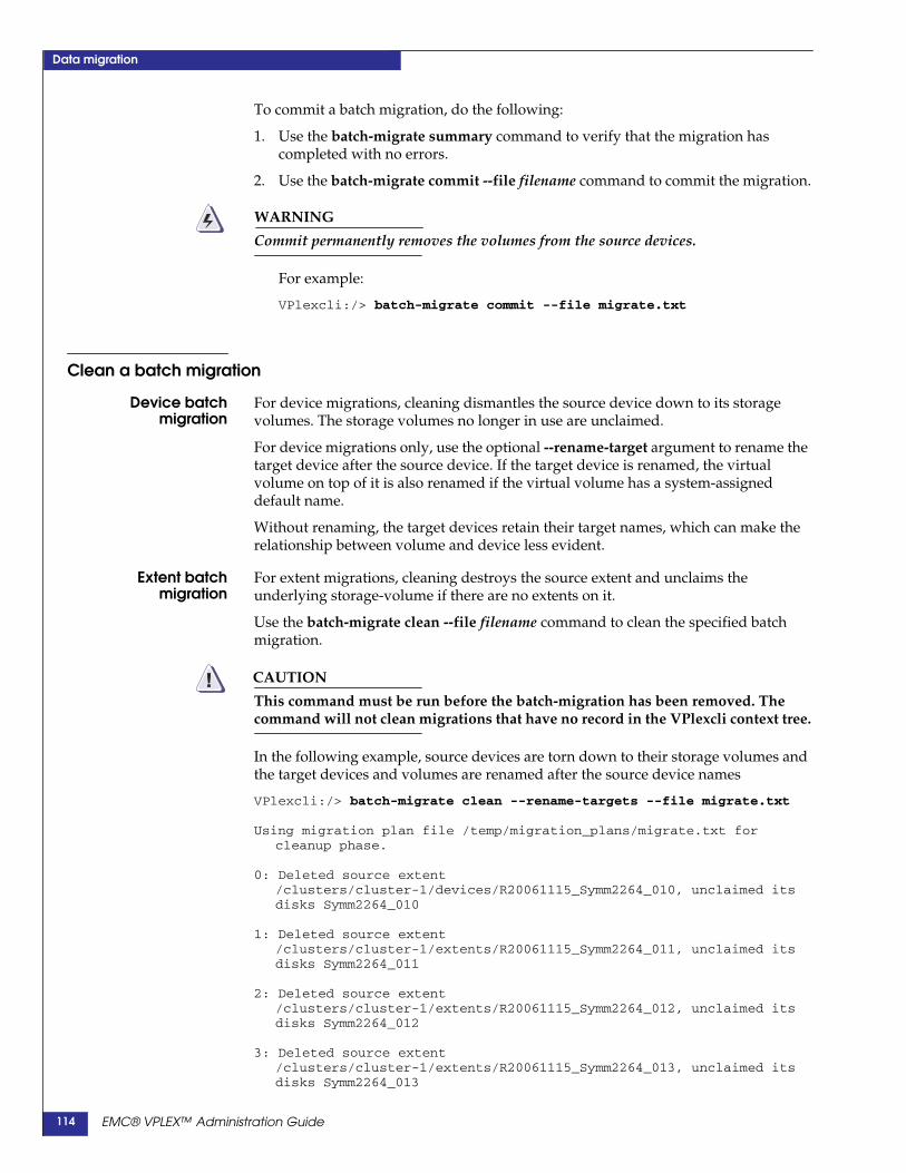
Data migration
To commit a batch migration, do the following:
1. Use the batch-migrate summary command to verify that the migration hascompleted with no errors.
2. Use the batch-migrate commit --file filename command to commit the migration.
WARNING
Commit permanently removes the volumes from the source devices.
For example:
VPlexcli:/> batch-migrate commit --file migrate.txt
Clean a batch migration
Device batchmigration
For device migrations, cleaning dismantles the source device down to its storagevolumes. The storage volumes no longer in use are unclaimed.
For device migrations only, use the optional --rename-target argument to rename thetarget device after the source device. If the target device is renamed, the virtualvolume on top of it is also renamed if the virtual volume has a system-assigneddefault name.
Without renaming, the target devices retain their target names, which can make therelationship between volume and device less evident.
Extent batchmigration
For extent migrations, cleaning destroys the source extent and unclaims theunderlying storage-volume if there are no extents on it.
Use the batch-migrate clean --file filename command to clean the specified batchmigration.
CAUTION!This command must be run before the batch-migration has been removed. Thecommand will not clean migrations that have no record in the VPlexcli context tree.
In the following example, source devices are torn down to their storage volumes andthe target devices and volumes are renamed after the source device names
VPlexcli:/> batch-migrate clean --rename-targets --file migrate.txt
Using migration plan file /temp/migration_plans/migrate.txt forcleanup phase.
0: Deleted source extent/clusters/cluster-1/devices/R20061115_Symm2264_010, unclaimed itsdisks Symm2264_010
1: Deleted source extent/clusters/cluster-1/extents/R20061115_Symm2264_011, unclaimed itsdisks Symm2264_011
2: Deleted source extent/clusters/cluster-1/extents/R20061115_Symm2264_012, unclaimed itsdisks Symm2264_012
3: Deleted source extent/clusters/cluster-1/extents/R20061115_Symm2264_013, unclaimed itsdisks Symm2264_013
EMC® VPLEX™ Administration Guide114

Data migration
Remove batch migration recordsRemove the migration record only if the migration has been committed or canceled.
Migration records are in the /data-migrations/device-migrations context.
Use the batch-migrate remove --file filename command to remove records for thespecified migration.
For example:
VPlexcli:/data-migrations/device-migrations> batch-migrate remove--file migrate.txt
or:
VPlexcli:>batch-migrate remove /data-migrations/device-migrations--file migrate.txt.
EMC® VPLEX™ Administration Guide 115

Data migration
EMC® VPLEX™ Administration Guide116

7
The two WAN ports on each VPLEX director support dual Gigabit Ethernetinter-cluster links.
The WAN ports are configured as part of the installation of a second cluster. Thischapter describes the CLI contexts and procedures to change the configurationcreated during installation.
This chapter covers the following topics:
◆ VPLEX hardware and WAN ports ................................................ 117◆ subnets context ................................................................................. 120◆ port-groups context.......................................................................... 121◆ option-sets context ........................................................................... 121
◆ Change a port group's network configuration ............................ 123◆ Change one port's IP address ......................................................... 126◆ Change a port-group's MTU size................................................... 126
VPLEX hardware and WAN portsVPLEX Geo clusters can include either of two types of director hardware. Thenumber and speed of the WAN ports on each type of director is as follows:
◆ VS1 - The Wide Area Network (WAN) communication interface card (SLiC) hasfour 1 Gigabit Ethernet (GbE) ports. Only two ports are used for VPLEX WANcommunications.
The ports are named GE00 and GE01.
◆ VS2 - WAN SLiC has two 10 Gigabit Ethernet (10 GbE) ports.
The ports are named XG00 and XG01.
WARNING
Data carried on WAN ports on both VS1 and VS2 directors and between clusters inVPLEX Metro and Geo configurations is not encrypted.
To prevent DNS attacks, the WAN ports should be routed only on secure and trustednetworks.
Configure the Network
EMC® VPLEX™ Administration Guide 117

Configure the Network
Refer to the EMC Simple Support Matrix (ESSM) for information about encryptiondevices supported in VPLEX configurations.
Port groupsAll ports named GE00 or XG00 (in a cluster) are collectively referred to as port-group0.
All ports named GE01 or XG01 (in a cluster) are collectively referred to as port-group1.
Note: Port group names (port-group-0 and port-group-1) can not be modified.
Geo WAN port configuration rulesGeo WAN ports must conform to the following rules:
◆ The two WAN ports on a director should be on different physical networks, andmust be on different subnets so that port GE00/XG00 (port group 0) can not seeport GE01/XG01 (port group 1) on any director.
◆ All port GE00/XG00s in the cluster (one from each director) must be in the samesubnet and connected to the same LAN. Ports in the same subnet are usuallyconnected to the same Ethernet switch.
◆ All port GE01/XG01s must be in one subnet, which cannot be the same subnetused for ports GE00/XG00.
◆ Each director must have 2 statically assigned IP addresses; one in each subnet.
◆ Each cluster must have an additional statically assigned IP address in each subnet(cluster IP address). This address is used during discovery. The cluster IP addressis not tied to a specific physical port. Any director may host the cluster IP address.
◆ The management port subnet can not be the same as either subnet used for theWAN ports.
EMC® VPLEX™ Administration Guide118
Configure the Network
CLI contextsThe parent context for configuring Ethernet and WAN connections is:
/clusters/cluster/cluster-connectivity
The /clusters/cluster/cluster-connectivity context includes the following addresses:
◆ discovery-address - The multicast address local directors use to discover thecluster.
Note: Multicast must be enabled on the local switch connecting the directors’Ethernet ports.
◆ discovery-port - The port local directors use (along with the discovery-address) tofind the other directors in same cluster.
◆ listening-port - The port local directors use to communicate with the othercluster. The listening port is used when connecting to the directors in the othercluster.
The default values for these three addresses should not be changed. They areused by the local directors to discover each other within the cluster.
IMPORTANT!The listening port must be open through any fire walls between clusters.
Use the set command to change the three addresses.
Use the set command with no arguments to display the allowed values for the threeaddresses:
VPlexcli:/clusters/cluster-1/cluster-connectivity> setattribute input-description------------------------ -----------------------------------------------------discovery-address Takes w.x.y.z where w,x,y,z are in [0..255]
e.g. 10.0.1.125.discovery-port Takes an integer between 1024 and 32767.listening-port Takes an integer between 1024 and 32767.name Read-only.remote-cluster-addresses Read-only.
A second set of addresses directly under the /clusters/cluster/ cluster-connectivitycontext are the
◆ remote-cluster-addresses - A list of reachable remote cluster addresses.
These are the cluster addresses assigned to the other cluster, both the one in theport-group-0 and the one in port-group-1. There are exactly 2.
To change a remote address, you must first clear the remote address.
Use the remote-clusters clear-addresses and remote-clusters add-addressescommands to add or clear entries in this list.
For example, to change address 42.29.20.214 to 42.29.20.254:
VPlexcli:/clusters/cluster-1/cluster-connectivity> remote-clusters clear-addresses--remote-cluster cluster-2 --addresses 42.29.20.214:11000
VPlexcli:/clusters/cluster-1/cluster-connectivity> remote-clusters add-addresses--remote-cluster cluster-2 --addresses 42.29.20.254:11000
EMC® VPLEX™ Administration Guide 119
Configure the Network
Alternatively, use the --default argument to create a default list of reachable IPaddresses (using the cluster-address attribute of the active subnets of remote clusters)for all remote clusters).
VPlexcli:/clusters/cluster-1/cluster-connectivity> remote-clusters add-addresses --default
Default values are determined by the cluster-address attribute of the active subnetsfrom all remote clusters. For example:
remote-cluster-addresses cluster-2[192.168.91.252:11000,192.168.101.252:11000]
New sub-contexts in Release 5.0Starting in GeoSynchrony 5.0, /clusters/cluster/cluster-connectivity has 3 newsub-contexts:
◆ “subnets context”
◆ “port-groups context”
◆ “option-sets context”
subnets contextA subnet is a logical subdivision of an IP network. VPLEX IP addresses are logicallydivided into two fields:
◆ A network or routing prefix.
On a VPLEX, the prefix attribute is really a prefix and subnet mask. specified asan IP address and subnet mask in integer dot notation, separated by a colon.
For example: 192.168.20.0:255.255.255.0
◆ A specific identifier for the configuration or the network interface.
IMPORTANT!VPLEX subnet addresses must be consistent, that is the cluster address and thegateway address must be in the subnet specified by the prefix.
If a change is made to the subnet, the change is validated and applied to all portsusing this subnet.
When re-configuring a port-group, there are multiple values that must be consistentwith each other. It may be necessary to clear or erase some attribute values beforeothers can be changed.
VPlexcli:/clusters/cluster-1/cluster-connectivity> cd subnets/
VPlexcli:/clusters/cluster-1/cluster-connectivity/subnets> llName--------------cluster-1-SN00cluster-1-SN01default-subnet
Use the following 4 CLI commands to create, modify, and delete subnets:
◆ subnet clear
◆ subnet create
EMC® VPLEX™ Administration Guide120

Configure the Network
◆ subnet destroy
◆ subnet modify
port-groups contextPorts named GE00/XG00 on each cluster are collectively referred to as port-group-0.There are two port-group-0s, one in each cluster. The port-group-0s on each clusterform one communication channel between the clusters.
Ports named GE01/XG01 on each cluster are collectively referred to as port-group-1.There are two port-group-1s, one in each cluster. The port-group-1s on each clusterform a second communication channel between the clusters.
The number of ports in each port-group varies depending on the number of enginesin each cluster.
In the following example, a VPLEX Geo configuration has 1 engine in each cluster:
VPlexcli:/clusters/cluster-1/cluster-connectivity> cd port-groups/
VPlexcli:/clusters/cluster-1/cluster-connectivity/port-groups> llName Subnet Option Set Enabled Member Ports------------ -------------- --------------- ----------- ------------------------------------------port-group-0 cluster-1-SN00 optionset-com-0 all-enabled engine-1-1|A2-XG00|192.168.11.140|enabled,
engine-1-1|B2-XG00|192.168.11.142|enabledport-group-1 cluster-1-SN01 optionset-com-1 all-enabled engine-1-1|A2-XG01|192.168.12.140|enabled,
engine-1-1|B2-XG01|192.168.12.142|enabled
Port-groups include the following properties:
◆ member-ports - A read-only list of ports that are part of this port-group,including their subnet, option-set, address and owner engine and director.
◆ option-set - The option-set associated with this port-group, or “inconsistent” ifthere is a problem in the configuration. This property is read-only.
◆ subnet - The subnet associated with this port-group, or “inconsistent” if there is aproblem in the configuration.
◆ enabled - Summarizes the 'enabled' status of the individual member ports.
• all-enabled - All member-ports in the port-group are enabled.
• all-disabled - All member-ports in the port-group are disabled.
• inconsistent - All member-ports don't have the same enabled status.
Use the set command to modify the subnet applied to a port-group:
VPlexcli:/clusters/cluster-1/cluster-connectivity/port-groups/port-group-1> set subnetcluster-1-SN01
VPlexcli:/clusters/cluster-1/cluster-connectivity/port-groups/port-group-1> llName Value------------ -----------------------------------------------------------------enabled all-enabledmember-ports A2-XG01 [cluster-1-SN01 optionset-com-1 engine-1-1 director-1-1-A
192.168.12.140 enabled], B2-XG01 [cluster-1-SN01 optionset-com-1engine-1-1 director-1-1-B 192.168.12.142 enabled]
option-set optionset-com-1subnet cluster-1-SN01
option-sets contextOption-sets group connection properties so that they can be collectively applied tothe ports contained in a port-group.
EMC® VPLEX™ Administration Guide 121
Configure the Network
Option sets include the following properties:
◆ connection-open-timeout - The time in seconds to wait for a response whenattempting to establish a connection.
Default: 3 seconds.
Range: 2 - 10 seconds.
◆ keepalive-timeout - The time in seconds to keep a connection open while it's idle.
Default: 10 seconds.
Range: 5 - 20 seconds.
◆ socket-buf-size - The receiving/sending buffer sizes in bytes.
Default: 20 MB.
Range: 16 KB - 256 MB.
CAUTION!Consult EMC Customer Support before changing the connection-open-timeoutand/or keepalive-timeout.
Use the set command to modify one or more properties of an option set:
VPlexcli:/clusters/cluster-1/cluster-connectivity/option-sets/optionset-com-1> setconnection-open-timeout 3sVPlexcli:/clusters/cluster-1/cluster-connectivity/option-sets/optionset-com-1> setkeepalive-timeout 10sVPlexcli:/clusters/cluster-1/cluster-connectivity/option-sets/optionset-com-1> setsocket-buf-size 10MVPlexcli:/clusters/cluster-1/cluster-connectivity/option-sets/optionset-com-1> llName Value----------------------- -----connection-open-timeout 3skeepalive-timeout 10ssocket-buf-size 10M
EMC® VPLEX™ Administration Guide122

Configure the Network
Modify the network configuration
About disabling port-groupsBefore disabling a port-group, always ensure complete connectivity through theother port-group.
WARNING
An inter-cluster link outage will occur if a port-group is disabled when there aremissing connections through the other port-group.
Change a port group's network configurationWhen network changes are made in the data center it may be necessary to change theconfiguration of a port group.
The general procedure to modify a port group includes the following steps:
1. Verify connectivity.
2. Disable the target port-group
3. Unassign the subnet
4. Change one or more subnet properties, as desired
5. Change member-port IP addresses, as desired
6. Change the option-set values, as desired
7. Re-apply the modified subnet to the port-group
8. Enable the target port-group
9. Update the remote-cluster address on the second cluster
10. Verify connectivity
The following section describes the procedure in greater detail:
1. Verify connectivity.
Use the connectivity validate-wan-com command to verify that all directors havecomplete connectivity through the other port group.
VPlexcli:/> connectivity validate-wan-comconnectivity: FULL
port-group-1 - OK - All expected connectivity is present.port-group-0 - OK - All expected connectivity is present.
2. Disable the target port-group
See About disabling port-groups on page 123.
Use the set command to disable the member ports in the target port-group:
VPlexcli:/clusters/cluster-1/cluster-connectivity/port-groups/port-group-1> set enabledall-disabled
3. Unassign the subnet
EMC® VPLEX™ Administration Guide 123

Configure the Network
Use the set subnet “ ” command to unassign the subnet from the port-group (set theport-group’s subnet value to null):
VPlexcli:/clusters/cluster-1/cluster-connectivity/port-groups/port-group-1> set subnet “”
4. Change one or more subnet properties, as desired
Use the subnet modify command to modify one or more subnet properties. Thesyntax for the command is:
subnet modify[-s|--subnet] subnet[-a|--cluster-address] address[-g|--gateway] IP address[-p|--prefix] prefix
Required argument:
[-s|--subnet] subnet - Context path of the subnet configuration to modify.
Optional arguments:
[-a|--cluster-address] address - The public address of the cluster to which thissubnet belongs.
[-g|--gateway] IP address - The gateway address for this subnet.
[-p|--prefix] prefix - The prefix/subnet mask for this subnet. Specified as an IPaddress and subnet mask in integer dot notation, separated by a colon. Forexample, 192.168.20.0:255.255.255.0
To modify the subnet’s public IP address:
VPlexcli:/clusters/cluster-1/cluster-connectivity/subnets/cluster-1-SN01> subnet modify--subnet cluster-1-SN01 --cluster-address 192.168.12.200
CAUTION!If the prefix is changed, ensure that the cluster IP address, gateway address, andport IP addresses are all consistent with the subnet prefix.
Use the ll command to display the addresses of the ports in the target port-group:
VPlexcli:/> ll /clusters/cluster-1/cluster-connectivity/port-groups/port-group-1
/clusters/cluster-1/cluster-connectivity/port-groups/port-group-1:Name Value------------ -----------------------------------------------------------------enabled all-enabledmember-ports engine-1-1|A2-XG01|192.168.10.140|enabled,
engine-1-1|B2-XG01|192.168.10.142|enabledoption-set optionset-com-1subnet -
5. Change member-port IP addresses, as desired
Use the set command to change the address of ports in the port-group to the newprefix:
VPlexcli:/> cd engines/engine-1-1/directors/director-1-1-A/hardware/ports/A2-XG01VPlexcli:/engines/engine-1-1/directors/director-1-1-A/hardware/ports/A2-XG01> set address192.168.12.140VPlexcli:/engines/engine-1-1/directors/director-1-1-A/hardware/ports/A2-XG01> cdengines/engine-1-1/directors/director-1-1-B/hardware/ports/B2-XG01VPlexcli:/engines/engine-1-1/directors/director-1-1-B/hardware/ports/B2-XG01> set address192.168.12.142
EMC® VPLEX™ Administration Guide124

Configure the Network
6. Change the option-set values, as desired
Use the set command to change option-set attribute values as desired:
VPlexcli:/clusters/cluster-1/cluster-connectivity/option-sets/optionset-com-1> setconnection-open-timeout 3s
7. Re-apply the modified subnet to the port-group
Use the set command to re-apply the modified subnet to the port-group:
VPlexcli:/clusters/cluster-1/cluster-connectivity/port-groups/port-group-1> set subnet/clusters/cluster-1/cluster-connectivity/subnets/cluster-1-SN01
Use the ll command to confirm the changes:
VVPlexcli:/clusters/cluster-1/cluster-connectivity/port-groups/port-group-1> llName Value------------ -----------------------------------------------------------------enabled all-disabledmember-ports A2-XG01 [cluster-1-SN01 optionset-com-1 engine-1-1 director-1-1-A
192.168.12.140 enabled], B2-XG01 [cluster-1-SN01 optionset-com-1engine-1-1 director-1-1-B 192.168.12.142 enabled]
option-set optionset-com-1subnet cluster-1-SN01
8. Enable the target port-group
Use the set command to enable the target port-group:
VPlexcli:/clusters/cluster-1/cluster-connectivity/port-groups/port-group-1> set enabledall-enabled
VPlexcli:/clusters/cluster-1/cluster-connectivity/port-groups/port-group-1> llName Value------------ -----------------------------------------------------------------enabled all-enabledmember-ports A2-XG01 [cluster-1-SN01 optionset-com-1 engine-1-1 director-1-1-A
192.168.12.140 enabled], B2-XG01 [cluster-1-SN01 optionset-com-1engine-1-1 director-1-1-B 192.168.12.142 enabled]
option-set optionset-com-1subnet cluster-1-SN01
9. Update the remote-cluster address on the second cluster
Use the remote-clusters clear-addresses command to clear the remote addresses.
VPlexcli:/clusters/cluster-1/cluster-connectivity> remote-clusters clear-addresses--remote-cluster cluster-2 --addresses 42.29.20.214:11000
Alternatively, use the remote-clusters add-addresses command with the --defaultargument to create a default list of reachable IP addresses (using the cluster-addressattribute of the active subnets of remote clusters) for all remote clusters).
VPlexcli:/clusters/cluster-1/cluster-connectivity> remote-clusters add-addresses --default
Default values are determined by the cluster-address attribute of the active subnetsfrom all remote clusters. For example:
remote-cluster-addresses cluster-2[192.168.91.252:11000,192.168.101.252:11000]
10. Verify connectivityUse the connectivity validate-wan-com command to verify connectivity:
VPlexcli:/> connectivity validate-wan-comconnectivity: FULL
EMC® VPLEX™ Administration Guide 125

Configure the Network
port-group-1 - OK - All expected connectivity is present.port-group-0 - OK - All expected connectivity is present.
Change one port's IP addressUse the set command to change a single WAN COM port's IP address to a differentaddress.
It is not necessary to first disable the port-group.
Use the ll command in port-group context to display the port name and address:
VPlexcli:/clusters/cluster-1/cluster-connectivity/port-groups> llName Subnet Option Set Enabled Member Ports------------ -------------- --------------- ----------- ------------------------------------------port-group-0 cluster-1-SN00 optionset-com-0 all-enabled engine-1-1|A2-XG00|192.168.11.140|enabled,
engine-1-1|B2-XG00|192.168.11.142|enabledport-group-1 cluster-1-SN01 optionset-com-1 all-enabled engine-1-1|A2-XG01|192.168.12.140|enabled,
engine-1-1|B2-XG01|192.168.12.142|enabled
Use the set command in the target port’s context to change the port’s IP address:
VPlexcli:/> cd engines/engine-1-1/directors/director-1-1-A/hardware/ports /A2-XG00
VPlexcli:/engines/engine-1-1/directors/director-1-1-A/hardware/ports/A2-XG00> set address192.168.10.140
Change a port-group's MTU sizeTo change the MTU size for both port groups, modify one port-group at a time.
Before disabling a port group, always ensure complete connectivity through the otherport group.
To change a port group's MTU size:
1. Verify connectivity.
Use the connectivity validate-wan-com command to verify that all directors havecomplete connectivity through the other port group.
VPlexcli:/> connectivity validate-wan-comconnectivity: FULL
port-group-1 - OK - All expected connectivity is present.port-group-0 - OK - All expected connectivity is present.
2. Disable the target port-group
See About disabling port-groups on page 123.
Navigate to the port-group context of the target port-group:
VPlexcli:/> cd /clusters/cluster-1/cluster-connectivity/port-groups/port-group-1VPlexcli:/clusters/cluster-1/cluster-connectivity/port-groups/port-group-1
Use the set command to disable the member ports in the target port-group:
VPlexcli:/clusters/cluster-1/cluster-connectivity/port-groups/port-group-1> set enabledall-disabled
3. Modify the MTU size in the subnet
EMC® VPLEX™ Administration Guide126
Configure the Network
Navigate to the subnet context for the subnet associated with the target port-group:
VPlexcli:/> cd /clusters/cluster-1/cluster-connectivity/subnets/cluster-1-SN01VPlexcli:/clusters/cluster-1/cluster-connectivity/subnets/cluster-1-SN01>
Use the set command to change the MTU (valid values are 96 - 9000):
CAUTION!The VPLEX CLI accepts MTU values lower than 96, but they are not supported.Entering a value less than 96 prevents the port-group from operating.
VPlexcli:/clusters/cluster-1/cluster-connectivity/subnets/cluster-1-SN01> set mtu 1480WARNING: Incompatible MTU settings on clusters. You must also set the MTU in subnet'cluster-2-SN01' (cluster-2) to 1480. Performance will be negatively impacted by incorrectsettings.
CAUTION!MTU size on the VPLEX and the attached switch must be the same.
Type the ll command to verify the new MTU on VPLEX:
VPlexcli:/clusters/cluster-1/cluster-connectivity/subnets/cluster-2-SN01> ll
Name Value---------------------- -------------------------cluster-address 192.168.2.252gateway 192.168.2.1mtu 1480...
Verify that the MTU size on VPLEX matches the MTU on attached switch.
Repeat for the second subnet.
4.Enable the port group
Navigate to the port-group context of the target port-group:
VPlexcli:/> cd /clusters/cluster-1/cluster-connectivity/port-groups/port-group-1VPlexcli:/clusters/cluster-1/cluster-connectivity/port-groups/port-group-1
Use the set command to enable the member ports in the target port-group:
VPlexcli:/clusters/cluster-1/cluster-connectivity/port-groups/port-group-1> set enabledall-enabled
5.Validate connectivity
Use the connectivity validate-wan-com command to verify that the directors havecomplete connectivity through all port groups.
VPlexcli:/> connectivity validate-wan-comconnectivity: FULL
port-group-1 - OK - All expected connectivity is present.port-group-0 - OK - All expected connectivity is present.
EMC® VPLEX™ Administration Guide 127
Configure the Network
EMC® VPLEX™ Administration Guide128
8
Consistency groups aggregate volumes to enable application of a set of commonproperties to the entire group.
Create consistency groups for sets of volumes that require the same I/O behavior inthe event of a failure.
This chapter describes the following topics and procedures:
◆ About VPLEX consistency groups ............................................... 130◆ Synchronous consistency groups................................................... 130◆ Asynchronous consistency groups ................................................ 133◆ Properties of consistency groups.................................................. 137◆ cache mode........................................................................................ 137◆ visibility ............................................................................................. 138◆ storage-at-clusters ............................................................................ 139◆ local-read-override........................................................................... 140◆ detach-rule......................................................................................... 140◆ auto-resume-at-loser ........................................................................ 141◆ virtual-volumes ................................................................................ 142◆ recoverpoint-enabled....................................................................... 142◆ Properties of asynchronous consistency groups ....................... 143◆ active cluster ..................................................................................... 143◆ default closeout-time ....................................................................... 144◆ maximum-queue-depth................................................................... 144◆ Manage consistency groups............................................................ 146◆ Manage consistency groups .......................................................... 146◆ Create a consistency group............................................................. 146◆ Add volumes to a consistency group............................................ 149◆ Remove volumes from a consistency group ................................ 150◆ Modify consistency group properties ........................................... 152◆ Display consistency groups ............................................................ 157◆ Operate a consistency group ......................................................... 166◆ Resolve a conflicting detach ........................................................... 166◆ Resume I/O after rollback .............................................................. 167◆ Resume I/O at the losing cluster ................................................... 169
Consistency groups
EMC® VPLEX™ Administration Guide 129

Consistency groups
About VPLEX consistency groupsVPLEX consistency groups aggregate volumes to enable the application of a commonset of properties to the entire group.
Consistency groups aggregate up to 1000 virtual volumes into a single entity that canbe managed as easily as individual volumes.
Consistency group detach rules define on which cluster I/O continues during clusteror inter-cluster link failures.
If all storage for an application with rollback capabilities is in a single consistencygroup, the application can recover from a complete cluster failure or inter-cluster linkfailure with little or no data loss. Data loss, if any is determined by the applicationdata access pattern and the consistency group’s cache-mode.
All consistency groups guarantee a crash consistent image of their membervirtual-volumes. In the event of a director, cluster, or inter-cluster link failure,consistency groups prevent possible data corruption.
Create consistency groups for sets of volumes that require the same I/O behaviorduring failures.
There are two types of consistency groups:
◆ “Synchronous consistency groups”
Synchronous consistency groups aggregate local and distributed volumes onVPLEX Local and VPLEX Metro systems separated by 5ms or less of latency.
◆ “Asynchronous consistency groups”
Asynchronous consistency groups aggregate distributed volumes on VPLEX Geosystems separated by 50ms or less of latency.
Note: In the current release, asynchronous consistency groups cannot be replicated byRecoverPoint.
A consistency group has either synchronous cache mode or asynchronous cachemode, but not both.
Synchronous consistency groupsSynchronous consistency groups provide a convenient way to apply rule sets andother properties to a group of volumes in a VPLEX Local or VPLEX Metro.
Synchronous consistency groups simplify configuration and administration on largesystems.
VPLEX supports up to 1024 synchronous consistency groups.
A synchronous consistency group:
EMC® VPLEX™ Administration Guide130

Consistency groups
◆ Contains up to 1000 virtual volumes.
◆ Contains either local or distributed volumes, (but not a mixture of both).
◆ Contains volumes with either global or local visibility.
◆ Uses write-through caching (known as synchronous cache mode in the VPLEXuser interface).
Write order fidelity is maintained by completing all writes to disk beforeacknowledging the write to the host.
Note: VPLEX Witness failure recovery semantics apply only to volumes in synchronousconsistency groups and only if a rule identifying specific preference is configured.
Figure 2 shows a synchronous consistency group that spans two clusters in a VPLEXMetro configuration.
◆ The hosts at both clusters write to the VPLEX distributed volumes in theconsistency group.
◆ VPLEX writes data to the back-end storage on both clusters
◆ An acknowledgment is returned to the host issuing the write.
This guarantees that the image on the back end storage is an exact copy on both sides.
Figure 2 Synchronous consistency group
Synchronousconsistency groups:
visibility
Synchronous consistency groups support either distributed or local volumes (but notboth in the same consistency group).
Cluster 1
Storage
Virtual Volume
Cluster 2
Storage
Virtual Volume
w
w
A
A61
w A43 w A43
2
5
EMC® VPLEX™ Administration Guide 131
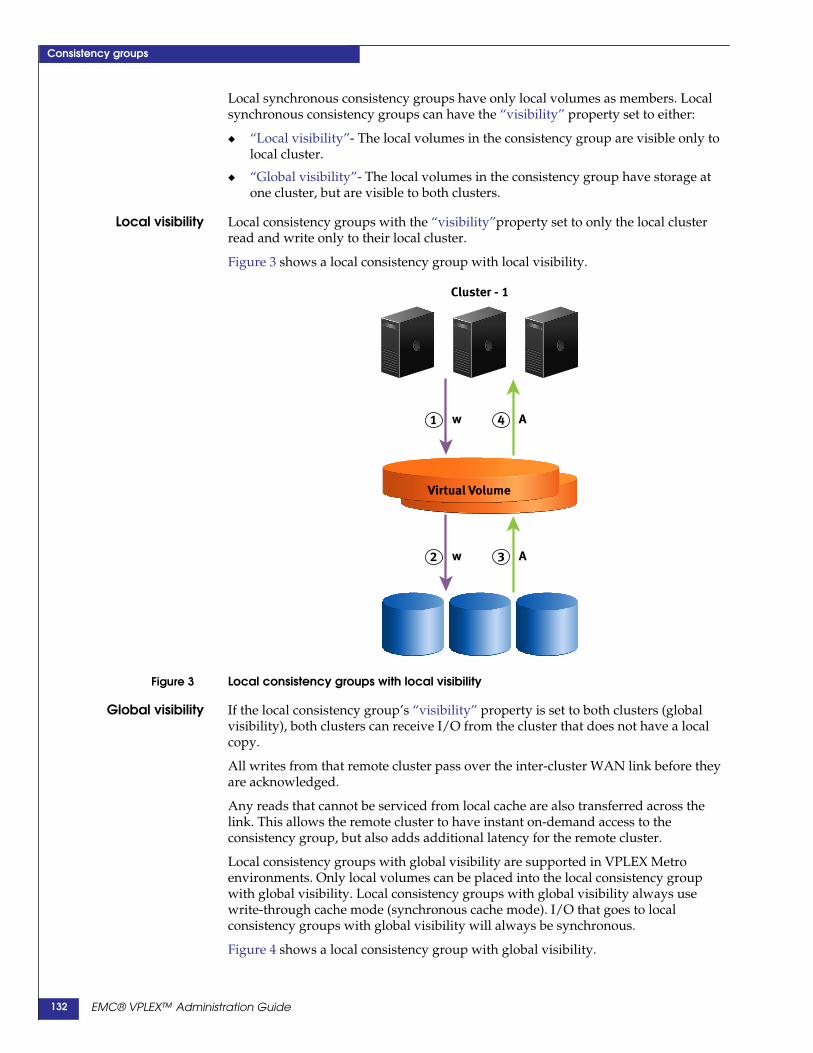
Consistency groups
Local synchronous consistency groups have only local volumes as members. Localsynchronous consistency groups can have the “visibility” property set to either:
◆ “Local visibility”- The local volumes in the consistency group are visible only tolocal cluster.
◆ “Global visibility”- The local volumes in the consistency group have storage atone cluster, but are visible to both clusters.
Local visibility Local consistency groups with the “visibility”property set to only the local clusterread and write only to their local cluster.
Figure 3 shows a local consistency group with local visibility.
Figure 3 Local consistency groups with local visibility
Global visibility If the local consistency group’s “visibility” property is set to both clusters (globalvisibility), both clusters can receive I/O from the cluster that does not have a localcopy.
All writes from that remote cluster pass over the inter-cluster WAN link before theyare acknowledged.
Any reads that cannot be serviced from local cache are also transferred across thelink. This allows the remote cluster to have instant on-demand access to theconsistency group, but also adds additional latency for the remote cluster.
Local consistency groups with global visibility are supported in VPLEX Metroenvironments. Only local volumes can be placed into the local consistency groupwith global visibility. Local consistency groups with global visibility always usewrite-through cache mode (synchronous cache mode). I/O that goes to localconsistency groups with global visibility will always be synchronous.
Figure 4 shows a local consistency group with global visibility.
Cluster - 1
Virtual Volume
w A32
w A41
EMC® VPLEX™ Administration Guide132
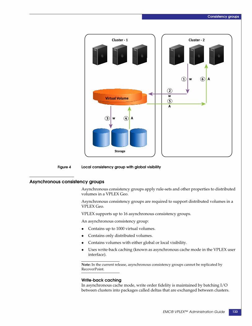
Consistency groups
Figure 4 Local consistency group with global visibility
Asynchronous consistency groupsAsynchronous consistency groups apply rule-sets and other properties to distributedvolumes in a VPLEX Geo.
Asynchronous consistency groups are required to support distributed volumes in aVPLEX Geo.
VPLEX supports up to 16 asynchronous consistency groups.
An asynchronous consistency group:
◆ Contains up to 1000 virtual volumes.
◆ Contains only distributed volumes.
◆ Contains volumes with either global or local visibility.
◆ Uses write-back caching (known as asynchronous cache mode in the VPLEX userinterface).
Note: In the current release, asynchronous consistency groups cannot be replicated byRecoverPoint.
Write-back cachingIn asynchronous cache mode, write order fidelity is maintained by batching I/Obetween clusters into packages called deltas that are exchanged between clusters.
Cluster - 1
Virtual Volume
Storage
w A
Cluster - 2
w A
w
A
1 6
2
5
43
EMC® VPLEX™ Administration Guide 133

Consistency groups
Each delta contains a group of writes that were initiated in the same window of time.All writes in one delta are guaranteed to be newer than all writes in the next delta.
Write order consistency is maintained on delta set boundaries, not on individualwrites.
Entire deltas are exchanged between clusters and committed to disks as a logical unit.
Each asynchronous consistency group maintains its own queue of deltas in variousstates:
• open - The delta is accepting new writes.
• closed - The delta is not accepting writes. Deltas are closed when their timerexpires or they are full
• exchanging - The delta's contents are being synchronized between theclusters.
• exchanged - The delta is exchanged with the remote cluster. The delta'scontents are the same at all clusters.
• committing- The delta's contents are being written out to the back-endstorage.
• committed - The write of the delta’s contents to the back-end storage iscomplete.
There can be only one delta in each state except closed.
There can be multiple deltas in the closed delta queue.
Before a delta is exchanged between clusters, data within the delta can vary bycluster. After a delta is exchanged and committed, data is exactly the same on bothclusters.
If access to the back end array is lost while the system is writing a delta, the data ondisk is no longer consistent and requires automatic recovery when access is restored.
Asynchronous cache mode can deliver better performance, but there is a higher riskthat data will be lost if:
◆ Multiple directors fail at the same time
◆ There is an inter-cluster link partition and both clusters are actively writing andinstead of waiting for the link to be restored, the user chooses to accept a datarollback in order to reduce the RTO
◆ The cluster that is actively writing fails
Asynchronousconsistency group:
active/passive
In an asynchronous consistency group, the host receives acknowledgment after thewrite reaches the VPLEX cache and has been protected to another director in the localcluster.
VPLEX collects writes at the cluster in the form of a delta. At a later point in time, theclusters exchange deltas creating a globally merged delta. The clusters sendcommunication messages back and forth between each other to facilitate theexchange.
EMC® VPLEX™ Administration Guide134

Consistency groups
Once the exchange is complete, the clusters write a global merged delta to theback-end arrays. Figure 5 shows a asynchronous consistency group configuration inan active/passive phase.
Figure 5 Asynchronous consistency group active/passive
In Figure 5, one cluster is actively reading and writing. This simplifies the view ofasynchronous I/O. Application data is written to the director in Cluster 1 andprotected in another director of Cluster 1.
VPLEX collects writes into a delta of a fixed size. Once that delta is filled or when aset time period (“default closeout-time”) has elapsed, the two clusters of the VPLEXGeo begin a communication process to exchange deltas.
The combination of the deltas is referred to as a global delta. In Figure 5, the globaldelta only includes the writes that occurred on Cluster 1 because Cluster 2 wasinactive. This data is then written to the back-end storage at Cluster 1 and Cluster 2.
VPLX-000431
Cluster 1
Storage
Virtual Volume
Cluster 2
Storage
Virtual Volume
1 2
A
3
4A
EMC® VPLEX™ Administration Guide 135

Consistency groups
Asynchronousconsistency group:
active/active
Figure 6 shows asynchronous I/O when both clusters are actively reading andwriting. The applications at Cluster 1 and Cluster 2 are both writing to their localVPLEX cluster.
Figure 6 Asynchronous consistency group active/active
Figure 6 shows I/O in an a synch or no us consistency group when both clusters areactively reading and writing. The applications at Cluster 1 and Cluster 2 are bothwriting to their local VPLEX cluster.
Application writes are acknowledged once each cluster caches the data in twodirectors. The VPLEX collects the data in deltas at each cluster. After the “defaultcloseout-time”, or after a deltas becomes full, the clusters exchange deltas. VPLEXthen writes the resulting delta to back end storage at each cluster.
This process coordinates data written to the storage at each cluster.
Asynchronousconsistency group:
RPO
The “default closeout-time” and “maximum-queue-depth” properties control therecovery point objective in the event of a failure.
The recovery point objective (RPO) is the maximum acceptable level of data lossresulting from a failure. RPO represents the point in time (prior to the failure) towhich lost data can be recovered.
Use the “maximum-queue-depth” and “default closeout-time” properties to controlthe RPO. Refer to “Calculating RPO in VPLEX Geo systems” on page 232.
Note: Both properties must be set sufficiently high to accommodate the latency and usablebandwidth between clusters.
Cluster 1
Storage
Virtual Volume
Cluster 2
Storage
Virtual Volume
1 2
A
3
4A
EMC® VPLEX™ Administration Guide136

Consistency groups
Properties of consistency groupsProperties of a consistency group are applied to all the virtual volumes in theconsistency group.
All consistency groups have configurable properties that determine I/O behavior,including:
◆ “cache mode”
◆ “visibility”
◆ “storage-at-clusters”
◆ “local-read-override”
◆ “detach-rule”
◆ “auto-resume-at-loser”
◆ “virtual-volumes”
◆ “recoverpoint-enabled”
Additional configurable properties are applicable only to consistency groups withasynchronous cache mode, including:
◆ “active cluster”
◆ “default closeout-time”
◆ “maximum-queue-depth”
IMPORTANT!When RecoverPoint is deployed, it may take up to 2 minutes for the RecoverPointcluster to take note of changes to a VPLEX consistency group. Wait for 2 minutesafter making the following changes to a VPLEX consistency group before creatingor changing a RecoverPoint consistency group:- Add/remove virtual volumes to/from a VPLEX consistency group- Enable/disable the recoverpoint-enabled property of a VPLEX consistency group- Change the detach rule of a VPLEX consistency group
cache modeCache mode describes how data is written to storage. Cache mode can be eithersynchronous or asynchronous:
◆ Synchronous cache mode - Supported on VPLEX Local and VPLEX Metroconfigurations where clusters are separated by up to 5 ms of latency. Insynchronous cache mode, writes to the back-end storage volumes are notacknowledged to the host until the back-end storage volumes acknowledge thewrite.
Writes to the virtual volumes in a synchronous consistency group are written todisk only if all prior acknowledged writes to all volumes in the consistency groupare also present on the disk.
◆ Asynchronous cache mode - Supported on VPLEX Geo configurations whereclusters separated by up to 50 ms of latency. In asynchronous cache mode, hostwrites to a distributed volume are acknowledged back to the host after the data isprotected in the cache of another director in the local cluster. These writes aregrouped into deltas.
EMC® VPLEX™ Administration Guide 137

Consistency groups
Writes to the virtual volumes in an asynchronous consistency group are orderedsuch that all the writes in a given delta are written before writes from the nextdelta.
A maximum of 16 consistency groups with asynchronous cache mode can beconfigured.
Each asynchronous consistency group can contain up to 1000 virtual volumes.
Use the set command in /clusters/cluster/consistency-groups/consistency-groupcontext to modify the cache mode property.
Note: Storage-at-clusters must be set to cluster-1 and cluster-2 before cache-mode can bechanged to asynchronous (asynchronous mode is supported only for DR volumes).
VPlexcli:/clusters/cluster-1/consistency-groups/TestCG> set cache-mode asynchronous
CAUTION!Changing cache mode for a non-empty consistency group that is receiving host I/Orequests may temporarily worsen I/O performance.
visibilityVisibility controls which clusters know about a consistency group.
Note: Visibility for consistency groups differs from the visibility property for devices. Devicescan have visibility set to local (visible only to the local cluster) or global (visible to bothclusters). All distributed devices have global visibility.
By default, a consistency groups’s visibility property is set only to the cluster wherethe consistency group was created. If a consistency group is created on cluster-2, it isinitially visible only on cluster-2.
The visibility of the volumes within the consistency group must match the visibilityof the consistency group.
If the visibility of a volume in a consistency group is set to local, the visibility of theconsistency group cannot be set to include other clusters. For example, if volume“LocalVolume” with visibility property set to “local” is added to consistency group‘TestCG” the visibility of TestCG cannot be modified to include other clusters.
In general, visibility is set to one of three options:
◆ Configure the consistency group to contain only volumes local to the local cluster.
◆ Configure the consistency group to contain only volumes that have storage at onecluster, but have global visibility.
◆ Configure the consistency group to contain only volumes that are distributedwith legs at both clusters.
When a consistency group’s visibility is set to a cluster, the consistency group appearsbelow /clusters/cluster-n/consistency-groups context for the cluster.
Note: The context for a specified consistency group appears in a cluster’s consistency groupCLI context only if the ““visibility”” property of the consistency group includes that cluster.
Under normal operations, the visibility property can be modified to expand from onecluster to both clusters.
EMC® VPLEX™ Administration Guide138

Consistency groups
Use the set command in /clusters/cluster/consistency-groups/consistency-groupcontext to modify the visibility property. If consistency group ‘TestCG” is visible onlyat cluster-1, use the set command to make it visible to cluster-1 and cluster-2:
VPlexcli:/clusters/cluster-1/consistency-groups/TestCG> set visibility cluster-1,cluster-2
If a consistency group contains virtual volumes with a given visibility (for example, amember volume’s visibility is “local”), the visibility property for the consistencygroup cannot be changed to conflict with the visibility property of the member virtualvolume.
For example, consistency group "TestCG" is visible only at cluster-1, and contains avolume "V" whose device is at cluster-1 and has local visibility. Both the followingcommands will fail, since the volume V is not visible at cluster-2.
VPlexcli:/clusters/cluster-1/consistency-groups/TestCG> set visibility cluster-1,cluster-2VPlexcli:/clusters/cluster-1/consistency-groups/TestCG> set visibility cluster-2
storage-at-clustersStorage-at-clusters tells VPLEX at which cluster the physical storage associated with aconsistency group is located.
The storage-at-clusters property of a consistency group must be a non-empty subsetof the consistency group’s “visibility” property.
◆ If visibility is set to one cluster, then storage-at-clusters must be exactly the sameas visibility.
◆ If visibility is set to two clusters (1 and 2), then storage-at-clusters can be one of:
• cluster-1
• cluster-2
• cluster-1 and cluster-2
A volume that does not have local storage at every cluster specified by thestorage-at-clusters property of a consistency group, cannot be added to theconsistency group.
For example, if a volume has storage only at cluster-1, it cannot be added to aconsistency group that has its storage-at-cluster property set to cluster-1 andcluster-2.
A volume that has local storage at more clusters than those specified by thestorage-at-clusters property of a consistency group, cannot be added to theconsistency group.
For example, if a volume has storage at cluster-1 and cluster-2, it cannot be added to aconsistency group that has its storage-at-cluster property set to cluster-1.
The storage-at-clusters property cannot be modified if doing so conflicts with thetopology of any of the volumes currently in the consistency group.
Use the set command in /clusters/cluster/consistency-groups/consistency-groupcontext to modify the storage-at-clusters property. For example, to set thestorage-at-clusters property to both clusters:
VPlexcli:/clusters/cluster-1/consistency-groups/TestCG> set storage-at-clusterscluster-1,cluster-2
Note: Best practice is to set the storage-at-clusters property when the consistency group isempty.
EMC® VPLEX™ Administration Guide 139
Consistency groups
local-read-overrideThe local-read-override property determines whether the volumes in this consistencygroup use the local read override optimization.
When a director receives a read request, it first checks the distributed cache to see ifthat page is dirty (written to some director's cache, but not yet written to disk). If thepage is dirty in any director's cache, the page is sent from that director to the readingdirector. The two directors can at be at the same cluster or in different clusters.
When a read request for a page is received by a director, and none of the directors inthe same cluster have that page in cache, it has two ways to get the page:
◆ Query the other directors in other clusters whether they have the page in theircaches.
◆ Read the page from the underlying back-end storage.
If no peer director has the page in its cache, the page is read from the underlyingback-end storage. The local-read-override property can be set to:
true (default)- A director reading from a volume in this consistency group prefers toread from back-end storage over getting the data from a peer director's cache.
false - A director reading from a volume in the consistency group prefers to readfrom a peer director’s cache.
Local-read-override should be set to true if the inter-cluster latency is large orback-end storage is fast and has a large cache of its own that enables it to respondfaster than the VPLEX director.
Local-read-override should be set to false only if it is faster to retrieve pages from theremote cluster's cache than from the local cluster’s storage. For example, if theclusters are located close to one another and the storage on the local cluster is veryslow.
Use the set command in/clusters/cluster/consistency-groups/consistency-group/advanced context to modifythe local-read-override property. For example, to disable local-read-override:
VPlexcli:/clusters/cluster-1/consistency-groups/TestCG/advanced> set local-read-overridefalse
detach-ruleDetach rules are a consistency group’s policy for automatically picking a “winning”cluster when there is an inter-cluster link outage. There are three consistency groupdetach rules:
◆ no-automatic-winner - The consistency group does not select a winning cluster.
◆ active-cluster-wins - Applicable only to asynchronous consistency groups. If onecluster was active and one was passive at the time of the link outage, theconsistency group selects the active cluster as the winner.
See “When a cluster is active vs. passive” on page 143.
◆ winner cluster-name delay seconds - Applicable only to synchronous consistencygroups. The cluster specified by cluster-name is declared the winner if aninter-cluster link outage lasts more than the number of seconds specified bydelay.
EMC® VPLEX™ Administration Guide140
Consistency groups
If a consistency group has a detach-rule configured, the rule applies to all volumes inthe consistency group, and overrides any rule-sets applied to individual volumes.
This property is not relevant for local consistency groups.
By default, no detach rule is configured for a consistency group.
Best practice is to apply detach rules to a consistency group that meet the needs ofyour application in terms of I/O continuance and data loss tolerance.
Use the consistency-group set-detach-rule commands to configure the detach-rule-for a consistency group:
◆ Use the “consistency-group set-detach-rule no-automatic-winner” command toset the detach-rule as no-automatic-winner:
VPlexcli:/clusters/cluster-1/consistency-groups/TestCG> set-detach-rule no-automatic-winner
◆ Use the “consistency-group set-detach-rule active-cluster-wins” command to setthe detach-rule as active-cluster-wins:
VPlexcli:/clusters/cluster-1/consistency-groups/TestCG> set-detach-rule active-cluster-wins
◆ Use the “consistency-group set-detach-rule winner” command to specify whichcluster is the winner, and the number of seconds VPLEX waits after a link outagebefore detaching the winning cluster:
VPlexcli:/clusters/cluster-1/consistency-groups/TestCG> set-detach-rule winner --clustercluster-1 --delay 5s
auto-resume-at-loserDetermines whether the loser automatically resumes I/O when the inter-cluster linkis repaired after a failure.
When the link is restored, the losing cluster finds out that it's the loser, and that thedata on the winning cluster is now different. The loser must determine whether tosuddenly change to the winner's data, or to keep suspending I/O.
By default, this property is set to false, that is auto-resume is disabled.
Leave this property set to false so as to give the administrator time to halt and restartthe application. Otherwise dirty data in the host’s cache may not be consistent withthe image on disk to which the winning cluster has been actively writing. If the hostflushes those dirty pages out of sequence, the data image may be corrupted.
true - I/O automatically resumes on the losing cluster after the inter-cluster link hasbeen restored.
Set auto-resume-at-loser to true only when the losing cluster is servicing a read-onlyapplication such as servicing web pages.
false (default) - I/O remains suspended on the losing cluster after the inter-clusterlink has been restored. I/O must be manually resumed.
Set auto-resume-at-loser to false for all applications that cannot tolerate a suddenchange in data.
CAUTION!For consistency groups where cache mode is set to asynchronous, settingauto-resume-at-loser to true may result in data loss.
EMC® VPLEX™ Administration Guide 141

Consistency groups
Setting this property to true can cause a spontaneous change of the view of datapresented to applications at the losing cluster when the inter-cluster link isrestored. Most applications cannot tolerate such a change.
Use the set command in the advanced context to configure the auto-resume propertyfor a consistency group:
VPlexcli:/clusters/cluster-1/consistency-groups/TestCG/advanced> set auto-resume-at-losertrue
virtual-volumesAdministrators can add and remove virtual volumes to a consistency group. In orderto be added to a consistency group, a virtual volume:
◆ Must not be a logging volume
◆ Have storage at every cluster in the 'storage-at-clusters' property of the targetconsistency group
◆ Must not be a member of any other consistency group
◆ Have no properties (detach rules, auto-resume) that conflict with those of theconsistency group.
Note: Virtual volumes with different properties are allowed to join a consistency group, butinherit the properties of the consistency group.
Use the “consistency-group list-eligible-virtual-volumes” command to displayvirtual volumes that are eligible to be added to a consistency group.
Use the “consistency-group add-virtual-volumes” command to add one or morevirtual volumes to a consistency group.
Use the ll /clusters/cluster/consistency-groups/ consistency-group command todisplay the virtual volumes in the specified consistency group.
Use the “consistency-group remove-virtual-volumes” command to remove one ormore virtual volumes from a consistency group.
recoverpoint-enabledStarting in Release 5.1, VPLEX includes a RecoverPoint splitter. The splitter “splits”application writes so that the writes are sent to their normally designated storagevolumes and a RecoverPoint Appliance (RPA) simultaneously.
To configure a consistency group for use with RecoverPoint:
◆ Cache mode must be synchronous
◆ Consistency groups with the “visibility” property set to both clusters must alsohave their “storage-at-clusters” set to both clusters in order to set therecoverpoint-enable property to true.
◆ All production and replica volumes associated with RecoverPoint must be in aVPLEX consistency group with the recoverpoint-enabled property set to true.
Configure two consistency groups for each set of virtual volumes to be protectedby RecoverPoint: one for the production volumes and one for the replica volumes.
RecoverPoint journal volumes are not required to be in a consistency group withthis attribute enabled.
EMC® VPLEX™ Administration Guide142
Consistency groups
In addition to setting this property to true, the VPLEX consistency group must bealigned with the RecoverPoint consistency group.
Use the set command in /clusters/cluster/consistency-groups/consistency-group/context to configure the recoverpoint-enabled property:
VPlexcli:/clusters/cluster-1/consistency-groups/TestCG> set recoverpoint-enabled true
Properties of asynchronous consistency groupsThe following configurable properties are applicable only to consistency groups withasynchronous cache mode.
active clusterThe active cluster property is not configurable by users. Instead, a configurationchanges dynamically between active/passive and active/active depending on thewrite activity at each cluster.
When a cluster isactive vs. passive
Failure behaviors dictated by the active-cluster-wins detach rule vary depending onwhether the configuration is active/passive or active/active at the time of the failure.
In asynchronous consistency groups, the process of synchronizing data between thetwo clusters includes the following phases:
◆ Open - Host writes to distributed volumes are acknowledged back to the hostafter the data is protected in the cache of another director in the local cluster.Writes from each application are collected into “deltas”.
◆ Closed - Deltas are closed when their timer expires or they are full.
◆ Exchanged - The delta is exchanged with the remote cluster.
◆ Commit - The delta's contents are written to back-end storage.
Data that has been protected to another director in the local cluster (but notexchanged with the remote cluster) is known as dirty data.
A configuration is active/passive if hosts at only one cluster were writing at the timeof the failure. A configuration is active/active if hosts at both clusters were writing atthe time of the failure.
A cluster is marked passive when all dirty data contributed by the cluster has beencommitted (written to the back end at both clusters). The cluster remains passive aslong as no further data is contributed by the time the next delta closes. Specifically:
◆ Hosts at a cluster stop writing to a consistency group.
◆ The currently open delta closes, either due to a timer (default-closeout-time) ordue to the delta becoming full at either cluster.
◆ The closed delta is exchanged and committed the back-end.
◆ The next open (empty at one cluster because the host is not writing) delta isclosed.
◆ When closure of the next delta completes without any new data, that cluster ismarked passive.
◆ When a host writes to a passive cluster (creates dirty data), the cluster is markedas active.
EMC® VPLEX™ Administration Guide 143
Consistency groups
default closeout-timeSets the default for the maximum time a delta remains open to accept new writes.Closeout-time can be set as either a positive integer or zero.
Default: 30 seconds.
zero (0) - There is no time limit on closing the open delta. The delta is closed when itis full and cannot accept more data.
A larger value for the default close-out -time unnecessarily exposes dirty data in theopen delta if the exchange delta is idle.
The ideal default close-out -time is equal to the time it takes to exchange a full deltaset.
The default closeout-time and maximum-queue-depth properties work together toallow administrators to fine-tune the maximum possible data loss in the event of aninter-cluster link outage.
Maximum RPO for the consistency group can be calculated as follows:
maximum-queue-depth x default closeout-time = RPO
Increasing either the default closeout-time or maximum-queue-depth propertyincreases the maximum RPO in the event of a inter-cluster link outage or clusterfailure.
Use the set command in/clusters/cluster/consistency-groups/consistency-group/advanced context toconfigure the closeout-time property for an asynchronous consistency group:
VPlexcli:/clusters/cluster-1/consistency-groups/TestCG/advanced> set closeout-time 12
maximum-queue-depthFor an asynchronous consistency group, this property configures the maximumpossible depth of the delta processing queues.
Each consistency group maintains its own queue of deltas in various states:
• open - The delta is accepting new writes
• closed - The delta is not accepting writes.
• exchanging - The delta's contents are being synchronized between theclusters.
• exchanged - The delta's contents are the same at all clusters.
• committing- The delta's contents are being written out to the back-endstorage.
• committed - The write of the delta’s contents to the back-end storage iscomplete.
All deltas pass through these states, forming a “pipeline” in the order in which theywere received. For applications that generate occasional brief bursts of writes, the rateof incoming writes may (for a short time) be faster than the rate at which deltas areexchanged and committed.
Setting the maximum queue depth allows multiple closed deltas to wait to beexchanged and committed.
EMC® VPLEX™ Administration Guide144

Consistency groups
The default closeout-time and maximum-queue-depth properties work together toallow administrators to fine-tune the maximum possible data loss in the event of aninter-cluster link outage.
Decrease the maximum-queue-depth to decrease the maximum RPO in the event of ainter-cluster link outage or cluster failure.
Increase the maximum-queue-depth to increase the ability of the system to handlebursts of traffic.
CAUTION!Increasing the maximum-queue-depth also increases the data that must rollback inthe case of a cluster failure or a link outage (I/O is resumed when the active clusterbecame the loser).
Default: 6.
Range: 6 - 64. The maximum value is platform-specific.
Use the set command in/clusters/cluster/consistency-groups/consistency-group/advanced context toconfigure the maximum-queue-depth property for an asynchronous consistencygroup:
VPlexcli:/clusters/cluster-1/consistency-groups/TestCG/advanced>set maximum-queue-depth 8
EMC® VPLEX™ Administration Guide 145

Consistency groups
Manage consistency groups
IMPORTANT!A key best practice for creating and managing consistency groups is to create a 1:1relationship between consistency groups and applications. All volumes (and onlythose volumes) required for an application should be in a single consistencygroup.
Create a consistency group
Before you begin Before you create a consistency group, consider how it will be used:
◆ Are the clusters more than 100km from one another or is latency greater than 5ms? Will the consistency group contain volumes on distributed devices? If yes,the cache mode must be set to asynchronous.
◆ At which cluster(s) is the underlying storage of the virtual volumes located? Ifvolumes are located at both clusters, set the storage-at-cluster property as“cluster-1,cluster-2”.
◆ Will I/O to the volumes in the consistency group be split by a RecoverPointAppliance? If yes, set the recoverpoint-enable property to “true”.
◆ What is the visibility of the virtual volumes to be added?
Some properties of virtual volumes and consistency groups limit which volumes canbe added to a consistency group, or prevent a property of the consistency group frombeing modified.
For example, a consistency group’s visibility property is set to “cluster-1”. Virtualvolumes local to cluster-1 are added. The visibility property of the consistency groupcan not be changed to either “cluster-2” or “cluster-1,cluster-2” since the volumes arenot visible at cluster-2.
Create a consistencygroup
To create a consistency group and configure those properties that should be set beforevirtual volumes are added, do the following:
1. Use the ls /clusters/*/consistency-groups/ command to display the names of allthe consistency-groups:
VPlexcli:/> ls /clusters/*/consistency-groups/
/clusters/cluster-1/consistency-groups:TestCG local_test test10 test11 test12 test13 test14test15 test16 test5 test6 test7 test8 test9vs_RAM_c1wins vs_RAM_c2wins vs_oban005 vs_sun190
/clusters/cluster-2/consistency-groups:TestCG local_test test10 test11 test12 test13 test14test15 test16 test5 test6 test7 test8 test9vs_RAM_c1wins vs_RAM_c2wins vs_oban005 vs_sun190
2. Use the consistency-group create command to create a new consistency-group ona cluster. The syntax for the command is:
consistency-group create[-n|--name]consistency-group name[-c|--cluster] cluster
EMC® VPLEX™ Administration Guide146

Consistency groups
[-n|--name] consistency-group name - Name of the new consistency-group. Mustbe unique on the entire VPLEX.
[-c|--cluster] cluster - Context path of the cluster at which to create theconsistency group. If the current context is a cluster or below, that cluster is thedefault. Otherwise, this argument is required.
Specify a name for the new consistency group that did not appear in the output inStep 1.
VPlexcli:/> consistency-group create --name TestCG --cluster cluster-1
3. Use the ls /clusters/cluster-id/consistency-groups/ consistency-group/ commandto display the new consistency-group:
VPlexcli:/> ls /clusters/cluster-1/consistency-groups/TestCG/
/clusters/cluster-1/consistency-groups/TestCG:
Attributes:Name Value------------------- --------------------------------------------active-clusters []cache-mode synchronousdetach-rule -operational-status [(cluster-1,{ summary:: ok, details:: [] })]passive-clusters []recoverpoint-enabled falsestorage-at-clusters []virtual-volumes []visibility [cluster-1]
Contexts:Name Description------------ -----------advanced -recoverpoint -
Set the visibilityproperty
By default, the consistency group’s “visibility” property is set to the cluster wherethe consistency group was created. If a consistency group is created on cluster-2,it is initially visible only on cluster-2.
Visibility can be configured as follows:
• cluster-1 - volumes local to cluster-1.
• cluster-2 - volumes local to cluster-2.
• cluster-1,cluster-2 - volumes that are distributed with legs at both clusters.
4. Use the set command to configure the consistency group’s visibility property.
CAUTION!The CLI context of the consistency group appears only at the cluster where theconsistency group has visibility. If visibility is set from cluster-1 to include onlycluster-2, the CLI context for the consistency group disappears at cluster-1 and isvisible only from cluster-2.
To set the consistency group’s visibility property to both clusters:
VPlexcli:/clusters/cluster-1/consistency-groups> set TestCG::visibility cluster-1,cluster-2
To set the consistency group’s visibility property to cluster-1:
EMC® VPLEX™ Administration Guide 147

Consistency groups
VPlexcli:/clusters/cluster-1/consistency-groups> set TestCG::visibility cluster-1
To set the consistency group’s visibility property to cluster-2:
VPlexcli:/clusters/cluster-1/consistency-groups> set TestCG::visibility cluster-2
Set thestorage-at-clusters
property
By default, the consistency group’s “storage-at-clusters” property is set to empty.
Storage-at-clusters tells VPLEX at which cluster the physical storage associatedwith a consistency group is located. If “visibility” is set to one cluster, thenstorage-at-clusters must be exactly the same as visibility. If visibility is set to twoclusters (1 and 2), then storage-at-clusters can be one of:
• cluster-1
• cluster-2
• cluster-1 and cluster-2
A volume that does not have local storage at every cluster specified by thestorage-at-clusters property of a consistency group, cannot be added to theconsistency group.
5. Use the set command to configure the consistency group’s storage-at-clustersproperty
VPlexcli:/clusters/cluster-1/consistency-groups> set TestCG::storage-at-clusterscluster-1,cluster-2
Set the cache-modeproperty
By default, the cache mode for the new consistency group is synchronous.
If this consistency group is intended to have synchronous cache mode, skip tostep 8.
6. Otherwise, use the set command to change the cache-mode to asynchronous:
VPlexcli:/clusters/cluster-1/consistency-groups> set TestCG::cache-mode asynchronous
Note: When you set the cache-mode to asynchronous, the CLI automatically applies theactive-cluster-wins rule.
When you set the cache mode to synchronous, the CLI automatically applies a winner rulewhere the winner is the cluster with the lowest cluster ID (typically cluster-1) and the time-outis five seconds.
(Optional) setadditional properties
7. Optionally, use one of the consistency-group set-detach-rule commands to applya detach rule.
For example; configure the detach-rule as active-cluster-wins:
VPlexcli:/clusters/cluster-1/consistency-groups/TestCG> set-detach-rule active-cluster-wins
8. Use the ll command to display the new consistency group:
VPlexcli:/clusters/cluster-1/consistency-groups/TestCG> ll
Attributes:Name Value------------------- ----------------------------------------------------------active-clusters []cache-mode asynchronousdetach-rule active-cluster-winsoperational-status [(cluster-1,{ summary:: ok, details:: [] }), (cluster-2,{
summary:: ok, details:: [] })]passive-clusters [cluster-1, cluster-2]recoverpoint-enabled falsestorage-at-clusters [cluster-1, cluster-2]
EMC® VPLEX™ Administration Guide148

Consistency groups
virtual-volumes []visibility [cluster-1, cluster-2]
Contexts:Name Description------------ -----------advanced -recoverpoint -
Refer to Table 8, “Display consistency group field descriptions,” for descriptions ofthe fields in the display.
Add volumes to a consistency groupA maximum number of 1000 volumes can be added to a consistency group.
All volumes used by the same application should be grouped together in aconsistency group.
Only volumes with storage at both clusters (distributed volumes) can be added toasynchronous consistency groups.
Only local volumes can be added to synchronous consistency groups with visibilityand storage-at-cluster set to the local cluster.
Remote volumes can be added to synchronous consistency groups with visibility setto both clusters and storage-at-cluster set to one cluster.
To add virtual volumes to an existing consistency group, do the following:
1. Navigate to the target consistency group’s context:
VPlexcli:/> cd clusters/cluster-1/consistency-groups/ TestCG
2. Use the consistency-group list-eligible-virtual-volumes command to displayvirtual volumes are eligible to be added to the consistency group:
VPlexcli:/clusters/cluster-1/consistency-groups/TestCG> consistency-grouplist-eligible-virtual-volumes[TestDDevice-1_vol, TestDDevice-2_vol, TestDDevice-3_vol, TestDDevice-4_vol,TestDDevice-5_vol]
3. Use the add-virtual-volumes command to add virtual volumes to the consistencygroup.
The syntax for the command is:
consistency-group add-virtual-volumes[-v|--virtual-volumes] virtual-volume,virtual-volume,...[-g|--consistency-group] consistency-group
[-v|--virtual-volumes] virtual-volume,virtual-volume,... - List of one or morecomma-separated glob patterns or context paths of the virtual volume(s) to add.
[-g|--consistency-group] consistency-group - Context path of the consistencygroup to which to add the specified virtual volume(s).
To add a single virtual volume:
VPlexcli:/clusters/cluster-2/consistency-groups/TestCG> add-virtual-volumes --virtual-volumesTestDDevice-2_vol
Note: The full path is not required if the volume name is unique in the VPLEX.
EMC® VPLEX™ Administration Guide 149

Consistency groups
To add multiple volumes using a single command, separate virtual volumes bycommas:
VPlexcli:/clusters/cluster-1/consistency-groups/TestCG> add-virtual-volumesTestDDevice-1_vol,TestDDevice-2_vol
4. Use the ll command to display the change:
VPlexcli:/clusters/cluster-1/consistency-groups/TestCG> ll
Attributes:Name Value------------------- ----------------------------------------------------------active-clusters []cache-mode asynchronousdetach-rule active-cluster-winsoperational-status [(cluster-1,{ summary:: ok, details:: [] }), (cluster-2,{
summary:: ok, details:: [] })]passive-clusters [cluster-1, cluster-2]recoverpoint-enabled falsestorage-at-clusters [cluster-1, cluster-2]virtual-volumes [TestDDevice-1_vol, TestDDevice-2_vol]visibility [cluster-1, cluster-2]
Contexts:Name Description------------ -----------advanced -recoverpoint -
Remove volumes from a consistency groupTo remove one or more virtual volumes from a consistency group:
1. Use the ll command to display the virtual volumes in the target consistencygroup:
VPlexcli:/clusters/cluster-1/consistency-groups/TestCG> ll
Attributes:Name Value------------------- ----------------------------------------------------------active-clusters []cache-mode asynchronousdetach-rule active-cluster-winsoperational-status [(cluster-1,{ summary:: ok, details:: [] }), (cluster-2,{
summary:: ok, details:: [] })]passive-clusters [cluster-1, cluster-2]recoverpoint-enabled falsestorage-at-clusters [cluster-1, cluster-2]virtual-volumes [TestDDevice-1_vol, TestDDevice-2_vol,
TestDDevice-3_vol,TestDDevice-4_vol,TestDDevice-5_vol]
visibility [cluster-1, cluster-2]
Contexts:Name Description------------ -----------advanced -recoverpoint -
2. Use the consistency-group remove-virtual-volumes command to remove one ormore virtual volumes.
EMC® VPLEX™ Administration Guide150

Consistency groups
WARNING
Before using consistency-group remove-virtual-volumes command on anasynchronous consistency group, ensure that no host applications are using thevolumes you are removing.
The syntax for the command is:
consistency-group remove-virtual-volumes[-v|--virtual-volumes] virtual-volume,virtual-volume,...[-g|--consistency-group context path
[-v|--virtual-volumes] virtual-volume,virtual-volume,... - *Glob pattern or a listof one or more comma-separated context paths of the virtual volume(s) to removefrom the consistency group.
[-g|--consistency-group] context path - * Context path of the consistency groupfrom which to remove the specified virtual volume.
Remove one virtual volume from the root context:
VPlexcli:/> consistency-group remove-virtual-volumes/clusters/cluster-1/virtual-volumes/TestDDevice-2_vol, --consistency-group/clusters/cluster-1/consistency-groups/TestCG
To remove multiple virtual volumes with a single command, separate the volumesusing commas:
VPlexcli:/> consistency-group remove-virtual-volumes/clusters/cluster-1/virtual-volumes/TestDDevice-2_vol,/clusters/cluster-1/virtual-volumes/TestDDevice-3_vol --consistency-group/clusters/cluster-1/consistency-groups/TestCG
Remove two virtual volumes from the target consistency group context:
VPlexcli:/clusters/cluster-1/consistency-groups/TestCG> remove-virtual-volumesTestDDevice-2_vol, TestDDevice-3_vol
3. Use the ls command to display the change:
VPlexcli:/> ls clusters/cluster-1/consistency-groups/TestCG
/clusters/cluster-1/consistency-groups/TestCG:
Attributes:Name Value------------------- ----------------------------------------------------------active-clusters []cache-mode asynchronousdetach-rule active-cluster-winsoperational-status [(cluster-1,{ summary:: ok, details:: [] }), (cluster-2,{
summary:: ok, details:: [] })]passive-clusters [cluster-1, cluster-2]recoverpoint-enabled falsestorage-at-clusters [cluster-1, cluster-2]virtual-volumes [TestDDevice-1_vol, TestDDevice-4_vol, TestDDevice-5_vol]visibility [cluster-1, cluster-2]
Contexts:Name Description------------ -----------advanced -recoverpoint -
EMC® VPLEX™ Administration Guide 151

Consistency groups
Modify consistency group properties
WARNING
Modifying cache-mode from synchronous to asynchronous when I/O is active issupported but may result in a disruption of access to data during the operation.
Schedule this activity during maintenance windows of low workload to reduceimpact on applications and possibility of a disruption.
Modifying cache-mode from asynchronous to synchronous is not supported.
Use the 3 consistency group set-detach rules to modify the “detach-rule” applied to aconsistency group:
◆ consistency-group set-detach-rule active-cluster-wins
◆ consistency-group set-detach-rule no-automatic-winner
◆ consistency-group set-detach-rule winner
Use the set command to modify the following properties of a consistency group:
All consistency groups:
◆ “cache mode”
◆ “visibility”
◆ “storage-at-clusters”
◆ “local-read-override”
◆ “auto-resume-at-loser”
Asynchronous consistency groups only:
◆ “default closeout-time”
◆ “maximum-queue-depth”
Synchronous consistency groups only:
◆ “recoverpoint-enabled”
The syntax for the set command is:
set[-d|--default][-f|--force][-a|--attributes] selector pattern[-v|--value] new value
[-d|--default] - Sets the specified attribute(s) to the default value(s), if any exist. If noattributes are specified, displays the default values for attributes in thecurrent/specified given context.
[-f|--force] - Force the value to be set, bypassing any confirmations or guards.
[-a|--attributes] selector pattern - Attribute selector pattern.
[-v|--value] new value - The new value to assign to the specified attribute(s).
To display which attributes are modifiable (writable) using the set command andtheir valid inputs:
VPlexcli:/clusters/cluster-1/consistency-groups/TestCG> setattribute input-description
EMC® VPLEX™ Administration Guide152

Consistency groups
--------------------------------------------------------------------------------------------------------------------active-clusters Read-only.cache-mode Takes one of 'asynchronous', 'synchronous' (case sensitive).detach-rule Read-only.name Takes a unique, non-empty and non-null name. A valid name starts with a letter or '_'
and contains only letters, numbers, '-' and '_'.operational-status Read-only.passive-clusters Read-only.recoverpoint-enabled falsestorage-at-clusters Takes a list with each element being a 'cluster' context or a context pattern.virtual-volumes Read-only.visibility Takes a list with each element being a 'cluster' context or a context pattern.
To display the current setting of a property:
VPlexcli:/> set /clusters/cluster-1/consistency-groups/TestCG::cache-modeattribute input-description---------------------------------------------------------------------------------------------------------------------/clusters/cluster-1/consistency-groups/TestCG::cache-mode Takes one of 'asynchronous','synchronous' (case sensitive).
To display the default values for the target consistency group:
VPlexcli:/clusters/cluster-1/consistency-groups/TestCG> set --defaultattribute default-value-------------------- -----------------active-clusters No default value.cache-mode No default value.detach-rule No default value.name No default value.operational-status No default value.passive-clusters No default value.recoverpoint-enabled No default value.storage-at-clusters No default value.virtual-volumes No default value.visibility No default value.
Example of modify: set visibilityTo change the visibility property from the target consistency group context:
VPlexcli:/clusters/cluster-1/consistency-groups/TestCG> set visibility cluster-1,cluster-2To change the visibility property from the consistency group context:
VPlexcli:/clusters/cluster-1/consistency-groups> set TestCG::visibility cluster-1,cluster-2To change the visibility property from the root context:
VPlexcli:/> set /clusters/cluster-1/consistency-groups/TestCG::visibility cluster-1,cluster-2
EMC® VPLEX™ Administration Guide 153

Consistency groups
Example of modify: apply a detach ruleTable 7 lists the applicable detach-rules for consistency groups with various settingsfor visibility, storage-at-clusters, and cache-mode.
To apply a detach rule that will determine the behavior of all volumes in aconsistency group:
1. Use the ll command to display the current detach rule (if any) applied to theconsistency group:
VPlexcli:/clusters/cluster-1/consistency-groups/TestCG2> llAttributes:Name Value-------------------- ----------------------active-clusters []cache-mode synchronousdetach-rule -...
2. Use one of the consistency-group set-detach-rule commands to apply adetach-rule to the consistency group:
Use the consistency-group set-detach-rule no-automatic-winner command to set thedetach-rule as no-automatic-winner.
In the following example, the command is used in the target consistency group’scontext:
VPlexcli:/clusters/cluster-1/consistency-groups/TestCG> set-detach-rule no-automatic-winnerUse the consistency-group set-detach-rule active-cluster-wins command to set thedetach-rule as active-cluster-wins.
In the following example, the command is used in the consistency group context:
VPlexcli:/clusters/cluster-1/consistency-groups> consistency-group set-detach-ruleactive-cluster-wins --consistency-groups TestCG
Use the consistency-group set-detach-rule winner command to specify whichcluster is the winner, and the number of seconds VPLEX waits after a link outagebefore detaching the winning cluster.
In the following example, the command is used in the root context:
VPlexcli:/> consistency-group set-detach-rule winner --cluster cluster-1 --delay 5s--consistency-groups TestCG
Table 7 Consistency groups detach-rules, visibility, storage-at-volumes, and cache-mode
visibility storage-at-clusters cache-mode Applicable detach-rule setting(s)
cluster-1 cluster-1 synchronous N/A
cluster-1 andcluster-2
cluster-1 andcluster-2
synchronous no-automatic-winnerwinner cluster-1winner cluster-2
cluster-1 andcluster-2
cluster-1 synchronous no-automatic-winnerwinner cluster-1
cluster-1 andcluster-2
cluster-1 andcluster-2
asynchronous no-automatic-winneractive-cluster-wins
EMC® VPLEX™ Administration Guide154

Consistency groups
Example of modify: enable local-read-override1. Use the ll command in the advanced context of the target consistency group to
display the current setting:
VPlexcli:/clusters/cluster-1/consistency-groups/TestCG2/advanced> llName Value-------------------------- --------auto-resume-at-loser falsecurrent-queue-depth -current-rollback-data -default-closeout-time -delta-size -local-read-override false...
2. Use the set command modify the local-read-override property:
VPlexcli:/clusters/cluster-1/consistency-groups/TestCG2/advanced> set local-read -overridetrue
3. Use the ll command to confirm the change:
VPlexcli:/clusters/cluster-1/consistency-groups/TestCG2/advanced> llName Value-------------------------- --------auto-resume-at-loser falsecurrent-queue-depth -current-rollback-data -default-closeout-time -delta-size -local-read-override true...
Example of modify: configure a consistency group for use with RecoverPointConsistency groups that will be used to contain RecoverPoint production source orreplica volumes must have the following properties:
◆ “cache mode” is synchronous (default value)
◆ Consistency groups with the “visibility” property set to both clusters must alsohave their “storage-at-clusters” set to both clusters
◆ “recoverpoint-enabled” property set to true.
In the following example, the visibility, storage-at-clusters, and recoverpoint-enabledproperties are modified to enable the consistency group to be used with recoverPoint.
VPlexcli:/clusters/cluster-1/consistency-groups/TestCG> set visibility cluster-1,cluster-2VPlexcli:/clusters/cluster-1/consistency-groups/TestCG> set storage-at-clusterscluster-1,cluster-2VPlexcli:/clusters/cluster-1/consistency-groups/TestCG> set recoverpoint-enabled trueVPlexcli:/clusters/cluster-1/consistency-groups/TestCG>lsAttributes:Name Value-------------------- ---------------------------------------------------------active-clusters []cache-mode synchronousdetach-rule winner cluster-1 after 10soperational-status [(cluster-1,{ summary:: ok, details:: [] }), (cluster-2,{
summary:: ok, details:: [] })]
EMC® VPLEX™ Administration Guide 155

Consistency groups
passive-clusters []recoverpoint-enabled truestorage-at-clusters [cluster-1, cluster-2]virtual-volumes []visibility [cluster-1, cluster-2]
Contexts:advanced recoverpoint
Delete a consistency group
WARNING
Before using the consistency-group destroy command on an asynchronousconsistency group, ensure that no host applications are using the consistency group.
To destroy an empty consistency group:
1. Use the ls command to verify that there are no virtual volumes in the consistencygroup (virtual volumes = [ ]).
VPlexcli:/> ls clusters/cluster-1/consistency-groups/ TestCG
Attributes:Name Value-------------------- ----------------------active-clusters []cache-mode synchronousdetach-rule -operational-status [ok]passive-clusters []recoverpoint-enabled falsestorage-at-clusters [cluster-1, cluster-2]virtual-volumes []visibility [cluster-1, cluster-2]...2. Use the consistency-group destroy command to delete the consistency group.
The syntax for the command is:
consistency-group destroy[-g|--consistency-group] consistency-group, consistency-group,...
[-g|--consistency-group] consistency-group, consistency-group, ... - List of one ormore comma-separated context paths of the consistency group(s) to destroy.
To delete a consistency group from the root context:
VPlexcli:/> consistency-group destroy clusters/cluster-1/ consistency-groups/TestCGWARNING: The following items will be destroyed:
Context---------------------------------------------/clusters/cluster-1/consistency-groups/TestCG
Do you wish to proceed? (Yes/No)Yes
To delete a consistency group from the consistency group context:
VPlexcli:/clusters/cluster-1/consistency-groups> destroy TestCGWARNING: The following items will be destroyed:
EMC® VPLEX™ Administration Guide156
Consistency groups
Context---------------------------------------------/clusters/cluster-1/consistency-groups/TestCG
Do you wish to proceed? (Yes/No)Yes
Display consistency groupsThis section describes the following topics:
◆ “Display consistency group names” on page 157
◆ “Display detailed listing of consistency groups” on page 157
◆ “Display operational status” on page 158
◆ “Display advanced properties” on page 158
◆ “Display recoverpoint properties” on page 159
◆ “Display operational status - inter-cluster link outage” on page 159
◆ “Display operational status - requires resume at loser” on page 159
For descriptions of the fields in the displays, see ““Display consistency group fielddescriptions” on page 161
Display consistency group namesUse the ls /clusters/*/consistency-groups command to display only the names ofconsistency groups on all clusters:
VPlexcli:/> ls /clusters/*/consistency-groups/
/clusters/cluster-1/consistency-groups:TestCG local_test test10 test11 test12 test13 test14test15 test16 test5 test6 test7 test8 test9vs_RAM_c1wins vs_RAM_c2wins vs_oban005 vs_sun190
/clusters/cluster-2/consistency-groups:TestCG local_test test10 test11 test12 test13 test14test15 test16 test5 test6 test7 test8 test9vs_RAM_c1wins vs_RAM_c2wins vs_oban005 vs_sun190
Use the ls /clusters/cluster-name/consistency-groups command to display the namesof consistency groups only on the specified cluster:
VPlexcli:/> ls /clusters/cluster-1/consistency-groups/
/clusters/cluster-1/consistency-groups:TestCG test10 test11 test12 test13 test14 test15 test16 test5 test6 test7test8 test9 vs_RAM_c1wins vs_RAM_c2winsvs_oban005 vs_sun190
Display detailed listing of consistency groupsUse the ll command in /clusters/cluster-name/consistency-groups context to displayan overview of the consistency groups.
Use this command to monitor the overall health of consistency groups and identifypoorly configured rules:
VPlexcli:/clusters/cluster-1/consistency-groups>llName Operational Status Active Passive Detach Rule Cache Mode------------------- ---------------------------- Clusters Clusters ------------------- ------------------------------- --------------------------- ---------- ---------- ------------------- ------------D850-008_view1 (cluster-1,{ summary:: ok, cluster-1 cluster-2 active-cluster-wins asynchronous
details:: [] }),
EMC® VPLEX™ Administration Guide 157

Consistency groups
(cluster-2,{ summary:: ok,details:: [] })
D850-008_view2 (cluster-1,{ summary:: ok, cluster-1, active-cluster-wins asynchronousdetails:: [] }), cluster-2(cluster-2,{ summary:: ok,details:: [] })
RAM_LR_cluster-1 (cluster-1,{ summary:: ok, - synchronousdetails:: [] }),(cluster-2,{ summary::unknown, details:: [] })
RAM_RR_cluster-2 (cluster-1,{ summary:: ok, no-automatic-winner synchronousdetails:: [] }),(cluster-2,{ summary:: ok,details:: [] })
.
.
.
Display operational statusUse the ls command in /clusters/cluster-name/consistency-groups/consistency-groupcontext to display the groups’ operational status.
In the following example, the command displays the operational status of aconsistency group on a healthy VPLEX:
VPlexcli:/> ls /clusters/cluster-1/consistency-groups/cg1
/clusters/cluster-1/consistency-groups/cg1:
VPlexcli:/clusters/cluster-1/consistency-groups/cg1> ls
Attributes:Name Value------------------- ----------------------------------------------------------active-clusters [cluster-1, cluster-2]cache-mode asynchronousdetach-rule no-automatic-winneroperational-status [(cluster-1,{ summary:: ok, details:: [] }),
(cluster-2,{ summary:: ok, details:: [] })]passive-clusters []recoverpoint-enabled falsestorage-at-clusters [cluster-1, cluster-2]virtual-volumes [dd1_vol, dd2_vol]visibility [cluster-1, cluster-2]
Contexts:Name Description------------ -----------advanced -recoverpoint -
Display advanced propertiesDisplay the advanced properties of a specified consistency group:
VPlexcli:/clusters/cluster-1/consistency-groups/cg1> ll /advanced
/clusters/cluster-1/consistency-groups/cg1/advanced:Name Value-------------------------- --------auto-resume-at-loser falsecurrent-queue-depth 1current-rollback-data 0Bdefault-closeout-time 0.5mindelta-size 0.25Mlocal-read-override truemax-possible-rollback-data 1.25M
EMC® VPLEX™ Administration Guide158

Consistency groups
maximum-queue-depth 6potential-winner -write-pacing inactive
Display recoverpoint propertiesDisplay the RecoverPoint properties of a specified consistency group:
VPlexcli:/clusters/cluster-1/consistency-groups/cg1> ll /recoverpoint
/clusters/cluster-1/consistency-groups/cg1/recoverpoint:Name Value--------------------------------- ---------------------------------------------------------------------recoverpoint-information [(device_storage_vol_1_7_vol,,,,),
(device_storage_vol_1_1_vol,CG_1,excedrin,10.6.210.79,ProductionSource),(device_storage_vol_1_2_vol,CG_1,excedrin,10.6.210.79,ProductionSource)]
vplex-rp-cg-alignment-indications ['device_storage_vol_1_7_vol' is not in a RecoverPoint consistencygroup and is not being protected.]
vplex-rp-cg-alignment-status error
Display operational status - inter-cluster link outageThe following example displays output of the ls command in /clusters/cluster-name/consistency-groups/consistency-group context during an inter-cluster link outage.
◆ The detach-rule is 'no-automatic-winner', so I/O stops at both clusters. VPLEXremains in this state until either the inter-cluster link restarts, or the userintervenes using the consistency-group choose-winner command.
◆ Status summary is 'suspended', showing that I/O has stopped
◆ Status details contain 'cluster-departure', indicating that the clusters can no longercommunicate with one another.
VPlexcli:/clusters/cluster-1/consistency-groups/cg1> ls
Attributes:Name Value------------------- ----------------------------------------------------------active-clusters [cluster-1, cluster-2]cache-mode asynchronousdetach-rule no-automatic-winneroperational-status [(cluster-1,{ summary:: suspended, details:: [cluster-departure] }),
(cluster-2,{ summary:: suspended, details:: [cluster-departure] })]passive-clusters []recoverpoint-enabled falsestorage-at-clusters [cluster-1, cluster-2]virtual-volumes [dd1_vol, dd2_vol]visibility [cluster-1, cluster-2]
Contexts:advanced recoverpoint
Display operational status - requires resume at loser◆ The ls command shows consistency group cg1 as ‘suspended,
requires-resume-at-loser’ on cluster-2 after cluster-2 is declared the losing clusterduring an inter-cluster link outage.
◆ The resume-at-loser command restarts I/O on cluster-2.
◆ The ls command displays the change in operational status:
VPlexcli:/clusters/cluster-1/consistency-groups/cg1> ls
Attributes:Name Value
EMC® VPLEX™ Administration Guide 159
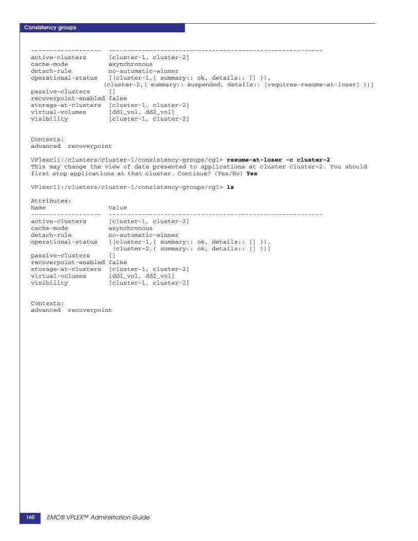
Consistency groups
------------------- ----------------------------------------------------------active-clusters [cluster-1, cluster-2]cache-mode asynchronousdetach-rule no-automatic-winneroperational-status [(cluster-1,{ summary:: ok, details:: [] }),
(cluster-2,{ summary:: suspended, details:: [requires-resume-at-loser] })]passive-clusters []recoverpoint-enabled falsestorage-at-clusters [cluster-1, cluster-2]virtual-volumes [dd1_vol, dd2_vol]visibility [cluster-1, cluster-2]
Contexts:advanced recoverpoint
VPlexcli:/clusters/cluster-1/consistency-groups/cg1> resume-at-loser -c cluster-2This may change the view of data presented to applications at cluster cluster-2. You shouldfirst stop applications at that cluster. Continue? (Yes/No) Yes
VPlexcli:/clusters/cluster-1/consistency-groups/cg1> ls
Attributes:Name Value------------------- ----------------------------------------------------------active-clusters [cluster-1, cluster-2]cache-mode asynchronousdetach-rule no-automatic-winneroperational-status [(cluster-1,{ summary:: ok, details:: [] }),
(cluster-2,{ summary:: ok, details:: [] })]passive-clusters []recoverpoint-enabled falsestorage-at-clusters [cluster-1, cluster-2]virtual-volumes [dd1_vol, dd2_vol]visibility [cluster-1, cluster-2]
Contexts:advanced recoverpoint
EMC® VPLEX™ Administration Guide160

Consistency groups
Table 8 Display consistency group field descriptions (1 of 5)
Property Description
Standard properties
“cache mode” Whether cache-mode is synchronous or asynchronous.Modifiable using the set command.synchronous (default) - Writes are done synchronously. Writes are not acknowledged to a hostunless they have been sent all the way to back-end storage at all clusters.asynchronous - Writes are done asynchronously. Writes are acknowledged when they are receivedby the cluster that receives them, and the data need not reach back-end storage, or indeed otherclusters, until after a delay.
“detach-rule” Policy for automatically picking a “winning” cluster when there is an inter-cluster link outage. Awinning cluster is intended to resume I/O operations when the link fails.For a synchronous consistency group the winning cluster will resume I/O operations shortly after thelink fails.For an asynchronous consistency group, the winning cluster prepares to resume I/O operations, butmay need to roll back the view of data in the process. If such a roll-back is required, I/O will remainsuspended until the administrator manually intervenes with the resume-after-rollback command.Modifiable using the following commands:consistency-group set-detach-rule active-cluster-wins - If one cluster was active and one waspassive at the time of the link outage, the group selects the active cluster as the winner.consistency-group set-detach-rule no-automatic-winner - The consistency group will not select awinning cluster.consistency-group set-detach-rule winner - The cluster specified by cluster-name will be declaredthe winner if an inter-cluster link outage lasts more than the number of seconds specified by delay.
“recoverpoint-enabled” Whether this consistency group can be used with RecoverPoint.Modifiable using the set command.true - The volumes in the consistency group can be used with RecoverPoint.false (default) - Integration with RecoverPoint is not enabled for volumes in the consistency group.
“storage-at-clusters” At which cluster the physical storage associated with a consistency group is located.Modifiable using the set command. If cluster names are “cluster-1” and “cluster-2” valid values are:cluster-1 - Storage associated with this consistency group is located only at cluster-1.cluster-2 - Storage associated with this consistency group is located only at cluster-2.cluster-1,cluster-2 - Storage associated with this consistency group is located at both cluster-1 andcluster-2.When modified, the new value cannot be incompatible with the volumes that are already in theconsistency group. Change storage-at-clusters only when the consistency group has no membervolumes.
“visibility” Lists the clusters at which this consistency group is visible.Modifiable using the set command. If cluster names are “cluster-1” and “cluster-2” valid values are:cluster-1 - This consistency group is visible only at cluster-1.cluster-2 - This consistency group is visible only at cluster-2.cluster-1,cluster-2 - This consistency group is visible at both cluster-1 and cluster-2.Changing this property changes where the consistency group is visible, and may cause contexts toappear or disappear in the context tree.
“virtual-volumes” Lists the virtual volumes that are members of the consistency group.Modifiable using the following commands:consistency-group add-virtual-volumes - Add one or more virtual volumes to a consistency group.consistency-group remove-virtual-volumes - Remove one or more virtual volumes from aconsistency group.
EMC® VPLEX™ Administration Guide 161

Consistency groups
Advanced properties
“auto-resume-at-loser” Determines whether IO automatically resumes at the detached cluster for the volumes in aconsistency group when the cluster regains connectivity with its peer cluster.Relevant only for multi-cluster consistency groups that contain distributed volumes. Modifiable usingthe set command. Set this property to true to allow the volumes to resume I/O without userintervention (using the resume-at-loser command).true - I/O automatically resumes on the losing cluster after the inter-cluster link has been restored.false (default) - I/O must be resumed manually after the inter-cluster link has been restored.
Note: Leave this property set to false to give administrators time to restart the application. Otherwise,dirty data in the host’s cache is not consistent with the image on disk to which the winning cluster hasbeen actively writing. Setting this property to true can cause a spontaneous change of the view ofdata presented to applications at the losing cluster. Most applications cannot tolerate this datachange. If the host flushes those dirty pages out of sequence, the data image may be corrupted.
“default closeout-time” Applicable only to asynchronous consistency groups. Modifiable using the set command.Maximum time for a delta to remain in the open state. When this value is positive, the firmware willattempt to close the open delta once it has been open for default-closeout-time seconds. When thisvalue is zero, there is no time limit on closing the open delta. The delta is closed when it cannotaccept more dirty data in the delta.Use this property to limit the maximum possible data loss in the event of an inter-cluster link outage.The ideal default close-out -time is equal to the time it takes to exchange a full delta set.Default: 30 seconds.zero (0) - There is no time limit on closing the open delta. The delta is closed when it is full andcannot accept more data.
“local-read-override” Applicable only to asynchronous consistency groups. Modifiable using the set command.Instructs VPLEX whether to prefer reading non-dirty pages from cache or from back-end storage.When a read request is received by a director it will first check with the distributed cache componentto see if that page is dirty (written to some director's cache, but not yet written to disk).If the page is dirty in any director's cache, the page is sent from that director to the reading director.This is the case when the two directors are in the same cluster and when the two directors are indifferent clusters.When a read request is received by a director, and the page is not dirty in any director's cache, andnone of the directors in the same cluster have that page in cache, it has two ways to get the page:• Query the directors in the other cluster whether they have the page in their caches, or• Read the page from the underlying back-end storage
Note: If none of the directors have the page in cache, the page is read from the underlying back-endstorage.
This property instructs VPLEX whether to prefer reading the page from directors in the other cluster,or to prefer reading the page from the back-end storage.false - The distributed cache will prefer to pull the page across the inter cluster link from the remotedirector's cache.true - (default) The distributed cache will prefer to read the page from the underlying back-endstorage.
“maximum-queue-depth” Applicable only to asynchronous consistency groups. Modifiable using the set command.Configures the maximum possible length of the delta processing queue.Default: 6Range: 6 - 64. Maximum value is platform specific.
Table 8 Display consistency group field descriptions (2 of 5)
Property Description
EMC® VPLEX™ Administration Guide162

Consistency groups
Recoverpoint properties
recoverpoint-information
vplex-rp-cg-alignment-indications
vplex-rp-cg-alignmentstatus
Display-only properties
active-clusters List of clusters which have recently written to a member volume in the consistency group.Applicable only to asynchronous consistency groups.For synchronous consistency groups, this property is always empty ([ ]).
current-rollback-data Applicable only to asynchronous consistency groups.Amount of data that would be discarded if that cluster were declared the winner during a link outageand rolled back its view of data to the last known consistent point.This includes all the data in the queue that has not yet been exchanged with the other cluster.This value depends on the current state of the system and changes over time.
current-queue-depth Applicable only to asynchronous consistency groups.Number of deltas or stages in the asynchronous data queue at the enclosing cluster.
delta-size Applicable only to asynchronous consistency groups.The maximum permitted size of a delta.Exception: the maximum-queue-size is reached, because I/O is being received faster than it can beexchanged between clusters and committed to back-end storage. The current open delta may exceedthis size until the delta at the head of the queue has been committed.
max-possible-rollback-data
An estimate of the maximum amount data that can be lost if at a single cluster within a volume set ifthere are multiple director failures within the cluster, a total cluster failure, or a total system failure.Roughly the product of current-queue-depth, delta-size, and the largest number of directors at anyone cluster.
operational status Current status for this consistency group with respect to each cluster on which it is visible.ok - I/O can be serviced on the volumes in the consistency group.suspended - I/O is suspended for the volumes in the consistency group. The reasons are describedin the “operational status: details”.degraded - I/O is continuing, but there are other problems described in “operational status: details”:unknown - The status is unknown, likely because of lost management connectivity.
Table 8 Display consistency group field descriptions (3 of 5)
Property Description
EMC® VPLEX™ Administration Guide 163

Consistency groups
operational status: details If operational status is “ok” this field is empty: “[ ]”. Otherwise, it displays additional information, whichmay be any of the following:temporarily-synchronous - This asynchronous consistency group has temporarily switched to'synchronous' cache mode because of a director failure.requires-resolve-conflicting-detach - After the inter-cluster link is restored, two clusters havediscovered that they have detached one another and resumed I/O independently. The clusters arecontinuing to service I/O on their independent versions of the data. The consistency-groupresolve-conflicting-detach command must be used to make the view of data consistent again at theclusters.rebuilding-across-clusters - One or more distributed member volumes is being rebuilt. At least onevolume in the group is out of date at that cluster and is re-syncing. If the link goes out at this time theentire group is suspended. Use the rebuild status command to display which volume is out of date atwhich cluster.rebuilding-within-cluster - One or more local rebuilds is in progress at this cluster.data-safe-failure - A single director has failed. The volumes are still crash-consistent, and will remainso, unless a second failure occurs before the first is recovered.requires-resume-after-data-loss-failure - There have been at least two concurrent failures, anddata has been lost. For example, a director fails shortly after the inter-cluster link fails, or when twodirectors fail at almost the same time. Use the consistency-group resume-after-data-loss-failurecommand to select a winning cluster and allow I/O to resume.cluster-departure - Not all the visible clusters are in communication.requires-resume-after-rollback - A cluster has detached its peer cluster and rolled back the view ofdata, but is awaiting the consistency-group resume-after-rollback command before resuming I/O.Displayed:• For an asynchronous consistency group where both clusters have been writing, that is where both
clusters are active.• At the winning side when a detach rule fires, or shortly after the consistency-group
choose-winner command picks a winning cluster.requires-resume-at-loser - Displayed on the losing side when the inter-cluster link heals after anoutage. After the inter-cluster link is restored, the losing cluster discovers that its peer was declaredthe winner and resumed I/O. Use the consistency-group resume-at-loser command to make theview of data consistent with the winner, and to resume I/O at the loser.restore-link-or-choose-winner - I/O is suspended at all clusters because of a cluster departure, andcannot automatically resume. This can happen if:• There is no detach-rule• If the detach-rule is 'no-automatic-winner', or• If the detach-rule cannot fire because its conditions are not met.For example, if more than one cluster is active at the time of an inter-cluster link outage, the'active-cluster-wins' rule cannot take effect. When this detail is present, I/O will not resume until eitherthe inter-cluster link is restored, or the user intervenes to select a winning cluster with theconsistency-group choose-winner command.unhealthy-devices - I/O has stopped in this consistency group because one or more volumes isunhealthy and cannot perform I/O.will-rollback-on-link-down - If there were a link-down now, the winning cluster would have to rollback the view of data in order to resume I/O.
passive-clusters Applicable only to asynchronous consistency groups.Clusters which have not recently written to a member volume.For synchronous consistency groups, the value of this attribute is always empty [ ].
Table 8 Display consistency group field descriptions (4 of 5)
Property Description
EMC® VPLEX™ Administration Guide164
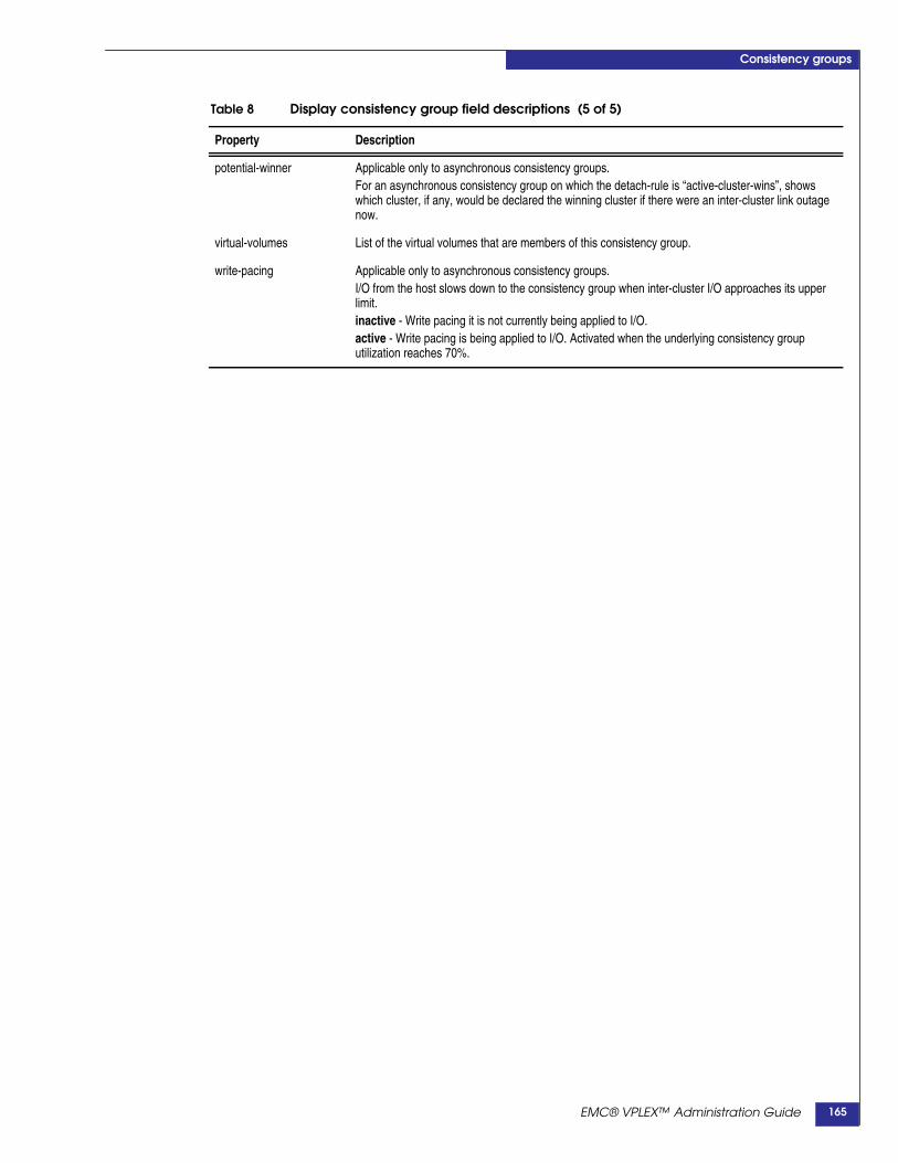
Consistency groups
potential-winner Applicable only to asynchronous consistency groups.For an asynchronous consistency group on which the detach-rule is “active-cluster-wins”, showswhich cluster, if any, would be declared the winning cluster if there were an inter-cluster link outagenow.
virtual-volumes List of the virtual volumes that are members of this consistency group.
write-pacing Applicable only to asynchronous consistency groups.I/O from the host slows down to the consistency group when inter-cluster I/O approaches its upperlimit.inactive - Write pacing it is not currently being applied to I/O.active - Write pacing is being applied to I/O. Activated when the underlying consistency grouputilization reaches 70%.
Table 8 Display consistency group field descriptions (5 of 5)
Property Description
EMC® VPLEX™ Administration Guide 165
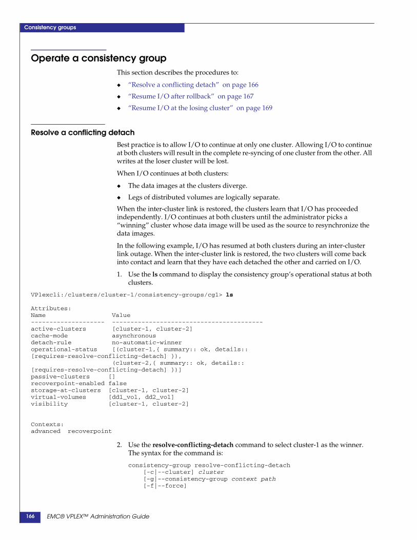
Consistency groups
Operate a consistency groupThis section describes the procedures to:
◆ “Resolve a conflicting detach” on page 166
◆ “Resume I/O after rollback” on page 167
◆ “Resume I/O at the losing cluster” on page 169
Resolve a conflicting detachBest practice is to allow I/O to continue at only one cluster. Allowing I/O to continueat both clusters will result in the complete re-syncing of one cluster from the other. Allwrites at the loser cluster will be lost.
When I/O continues at both clusters:
◆ The data images at the clusters diverge.
◆ Legs of distributed volumes are logically separate.
When the inter-cluster link is restored, the clusters learn that I/O has proceededindependently. I/O continues at both clusters until the administrator picks a“winning” cluster whose data image will be used as the source to resynchronize thedata images.
In the following example, I/O has resumed at both clusters during an inter-clusterlink outage. When the inter-cluster link is restored, the two clusters will come backinto contact and learn that they have each detached the other and carried on I/O.
1. Use the ls command to display the consistency group’s operational status at bothclusters.
VPlexcli:/clusters/cluster-1/consistency-groups/cg1> ls
Attributes:Name Value-------------------- -----------------------------------------active-clusters [cluster-1, cluster-2]cache-mode asynchronousdetach-rule no-automatic-winneroperational-status [(cluster-1,{ summary:: ok, details::[requires-resolve-conflicting-detach] }),
(cluster-2,{ summary:: ok, details::[requires-resolve-conflicting-detach] })]passive-clusters []recoverpoint-enabled falsestorage-at-clusters [cluster-1, cluster-2]virtual-volumes [dd1_vol, dd2_vol]visibility [cluster-1, cluster-2]
Contexts:advanced recoverpoint
2. Use the resolve-conflicting-detach command to select cluster-1 as the winner.The syntax for the command is:
consistency-group resolve-conflicting-detach[-c|--cluster] cluster[-g|--consistency-group context path[-f|--force]
EMC® VPLEX™ Administration Guide166

Consistency groups
[-c|--cluster] cluster - * The cluster whose data image will be used as the source toresynchronize the data images on both clusters.
[-g|--consistency-group] consistency-group - * The consistency group on whichto resolve the conflicting detach.
VPlexcli:/clusters/cluster-1/consistency-groups/cg1> resolve-conflicting-detach -c cluster-1This will cause I/O to suspend at clusters in conflict with cluster cluster-1, allowing you tostop applications at those clusters. Continue? (Yes/No) Yes
Cluster-2’s modifications to data on volumes in the consistency group since thelink outage started are discarded.
Cluster-2's data image is then synchronized with the image at cluster-1.
I/O will suspend at cluster-2 if the auto-resume policy is false.
3. Use the ls command to verify the change in operation status:
VPlexcli:/clusters/cluster-1/consistency-groups/cg1> ls
Attributes:Name Value------------------- ----------------------------------------------------------active-clusters [cluster-1, cluster-2]cache-mode asynchronousdetach-rule no-automatic-winneroperational-status [(cluster-1,{ summary:: ok, details:: [] }),
(cluster-2,{ summary:: suspended, details:: [requires-resume-at-loser] })]passive-clusters []recoverpoint-enabled falsestorage-at-clusters [cluster-1, cluster-2]virtual-volumes [dd1_vol, dd2_vol]visibility [cluster-1, cluster-2]
Contexts:advanced recoverpoint
• At cluster-1, I/O continues, and the status is ‘ok’.
• At cluster-2, the view of data has changed and so I/O is suspended.
4. Use the consistency-group resume-at-loser command to resume I/O to theconsistency group on cluster-2.
Resume I/O after rollback
WARNING
In a Geo configuration, on a cluster that successfully vaulted and unvaulted, the usershould contact EMC Engineering for assistance before rolling back the data prior tore-establishing communication with the non-vaulting cluster.
If the losing cluster is active at the onset of a cluster or inter-cluster-link outage, thedistributed cache at the losing cluster contains dirty data.
Without that data, the winning cluster's data image is inconsistent. Resuming I/O atthe winner requires rolling back the winner's data image to the last point where theclusters agreed.
This can cause a sudden change in the data image.
Many applications cannot tolerate sudden data changes, so the roll-back andresumption of I/O requires manual intervention.
EMC® VPLEX™ Administration Guide 167

Consistency groups
The delay gives the administrator the chance to halt applications before changing thedata image. The data image is rolled back as soon as a winner is chosen (eithermanually or automatically using a detach rule).
The resume-after-rollback command acknowledges that the application is ready forrecovery (this may involve application failure and/or rebooting the host).
Note: It is recommended to reboot the hosts of affected applications.
1. Use the ls command to display the consistency group on the winning clusterduring an inter-cluster link outage.
Because the consistency group is asynchronous, I/O remains suspended.
VPlexcli:/clusters/cluster-1/consistency-groups/cg1> ls
Attributes:Name Value-------------------- -------------------------------------------active-clusters []cache-mode asynchronousdetach-rule -operational-status [suspended, requires-resume-after-rollback]passive-clusters [cluster-1, cluster-2]recoverpoint-enabled falsestorage-at-clusters [cluster-1, cluster-2]virtual-volumes [dd1_vol]visibility [cluster-1, cluster-2
Contexts:advanced recoverpoint
2. Use the resume-after-rollback command to acknowledge that the application isready for recovery.
VPlexcli:/clusters/cluster-1/consistency-groups/cg1> resume-after-rollback--consistency-group cg1This will change the view of data at cluster cluster-1, so you should ensure applications arestopped at that cluster. Continue? (Yes/No) Yes
3. Use the ls command to display the change in operational status.
VPlexcli:/clusters/cluster-1/consistency-groups/cg1> ls
Attributes:Name Value-------------------- ----------------------active-clusters [cluster-1]cache-mode asynchronousdetach-rule -operational-status [ok]passive-clusters [cluster-2]recoverpoint-enabled falsestorage-at-clusters [cluster-1, cluster-2]virtual-volumes [dd1_vol]visibility [cluster-1, cluster-2]
Contexts:advanced recoverpoint
EMC® VPLEX™ Administration Guide168

Consistency groups
Resume I/O at the losing clusterDuring an inter-cluster link outage, an administrator may permit I/O to resume atone of the two clusters: the “winning” cluster.
I/O remains suspended on the “losing” cluster.
When the inter-cluster link heals, the winning and losing clusters re-connect, and thelosing cluster discovers that the winning cluster has resumed I/O without it.
Unless explicitly configured otherwise (using the “auto-resume-at-loser” property),I/O remains suspended on the losing cluster. This prevents applications at the losingcluster from experiencing a spontaneous data change.
The delay allows the administrator to shut down applications.
After stopping the applications, the administrator can use the consistency-groupresume-at-loser command to:
◆ Resynchronize the data image on the losing cluster with the data image on thewinning cluster,
◆ Resume servicing I/O operations.
The administrator may then safely restart the applications at the losing cluster.
To restart I/O on the losing cluster:
1. Use the ls command to display the operational status of the target consistencygroup.
VPlexcli:/clusters/cluster-1/consistency-groups/cg1> ls
Attributes:Name Value------------------- ----------------------------------------------------------active-clusters [cluster-1, cluster-2]cache-mode asynchronousdetach-rule no-automatic-winneroperational-status [(cluster-1,{ summary:: ok, details:: [] }),
(cluster-2,{ summary:: suspended, details:: [requires-resume-at-loser] })]passive-clusters []recoverpoint-enabled falsestorage-at-clusters [cluster-1, cluster-2]virtual-volumes [dd1_vol, dd2_vol]visibility [cluster-1, cluster-2]
Contexts:advanced recoverpoint
2. Use the consistency-group resume-at-loser to restart I/O on the losing cluster.The syntax for the command is:
consistency-group resume-at-loser[-c|--cluster] cluster[-s|--consistency-group] consistency-group[-f|--force]
[-c|--cluster] cluster - The cluster on which to roll back and resume I/O.
[-g|--consistency-group] consistency-group - The consistency group on which toresynchronize and resume I/O.
VPlexcli:/clusters/cluster-1/consistency-groups/cg1> resume-at-loser -c cluster-2This may change the view of data presented to applications at cluster cluster-2. You shouldfirst stop applications at that cluster. Continue? (Yes/No) Yes
EMC® VPLEX™ Administration Guide 169
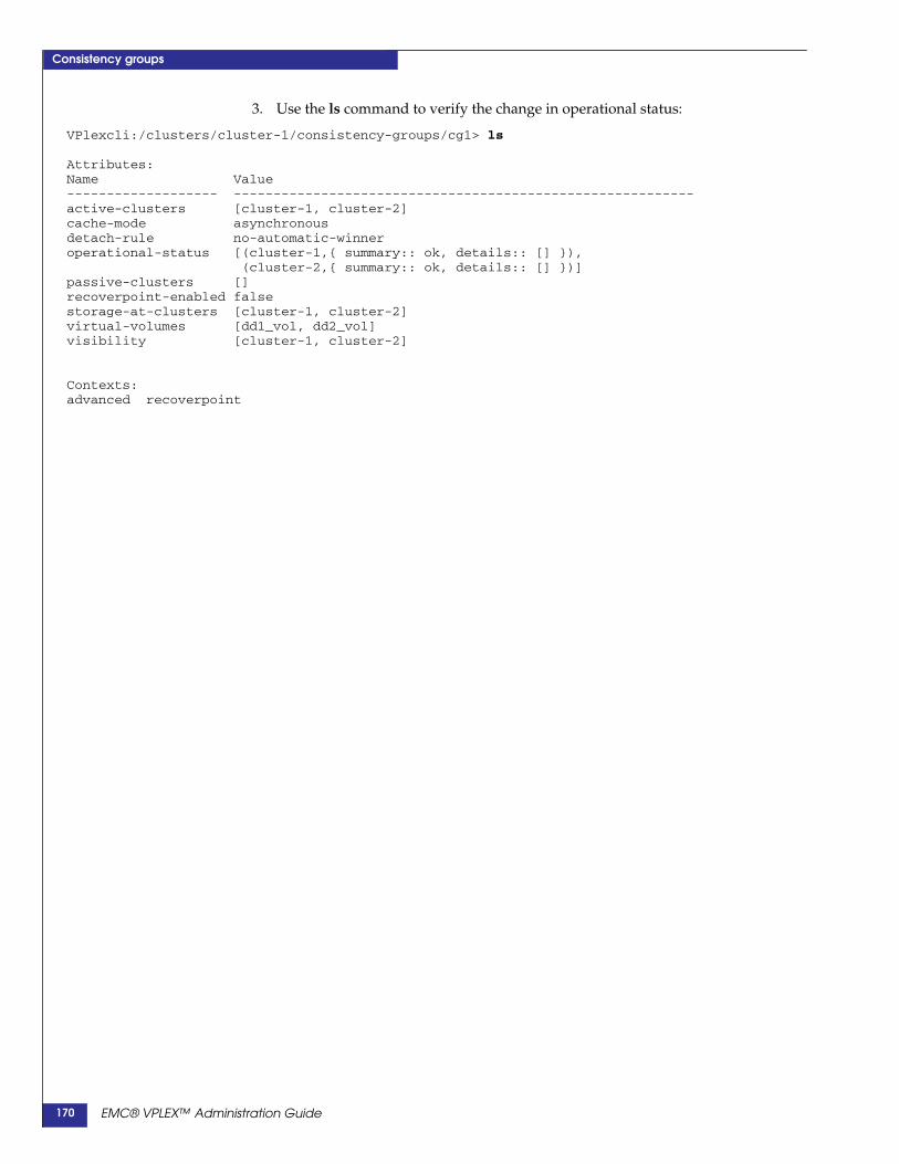
Consistency groups
3. Use the ls command to verify the change in operational status:
VPlexcli:/clusters/cluster-1/consistency-groups/cg1> ls
Attributes:Name Value------------------- ----------------------------------------------------------active-clusters [cluster-1, cluster-2]cache-mode asynchronousdetach-rule no-automatic-winneroperational-status [(cluster-1,{ summary:: ok, details:: [] }),
(cluster-2,{ summary:: ok, details:: [] })]passive-clusters []recoverpoint-enabled falsestorage-at-clusters [cluster-1, cluster-2]virtual-volumes [dd1_vol, dd2_vol]visibility [cluster-1, cluster-2]
Contexts:advanced recoverpoint
EMC® VPLEX™ Administration Guide170

9
This chapter describes VPLEX Witness, including:
◆ Introduction ...................................................................................... 172◆ Handling failures when VPLEX Witness is not deployed: detach rules 173◆ Failures in Metro systems without/with VPLEX Witness......... 175◆ Failures in Geo systems without/with VPLEX Witness ............ 178
◆ Install, enable, and manage VPLEX Witness............................. 183◆ Installation considerations .............................................................. 183◆ CLI context ........................................................................................ 183◆ Enable/disable VPLEX Witness client .......................................... 184◆ Renew the VPLEX Witness security certificate............................ 184
◆ VPLEX Witness operation ............................................................. 185◆ Normal operation............................................................................. 187◆ Single failures (no data unavailability) ......................................... 187◆ Dual failures (no data unavailability) ........................................... 189◆ Single failures (data unavailability at one cluster) ...................... 190◆ Dual failure (cluster isolation/DU at one cluster)....................... 193
VPLEX Witness
EMC® VPLEX™ Administration Guide 171
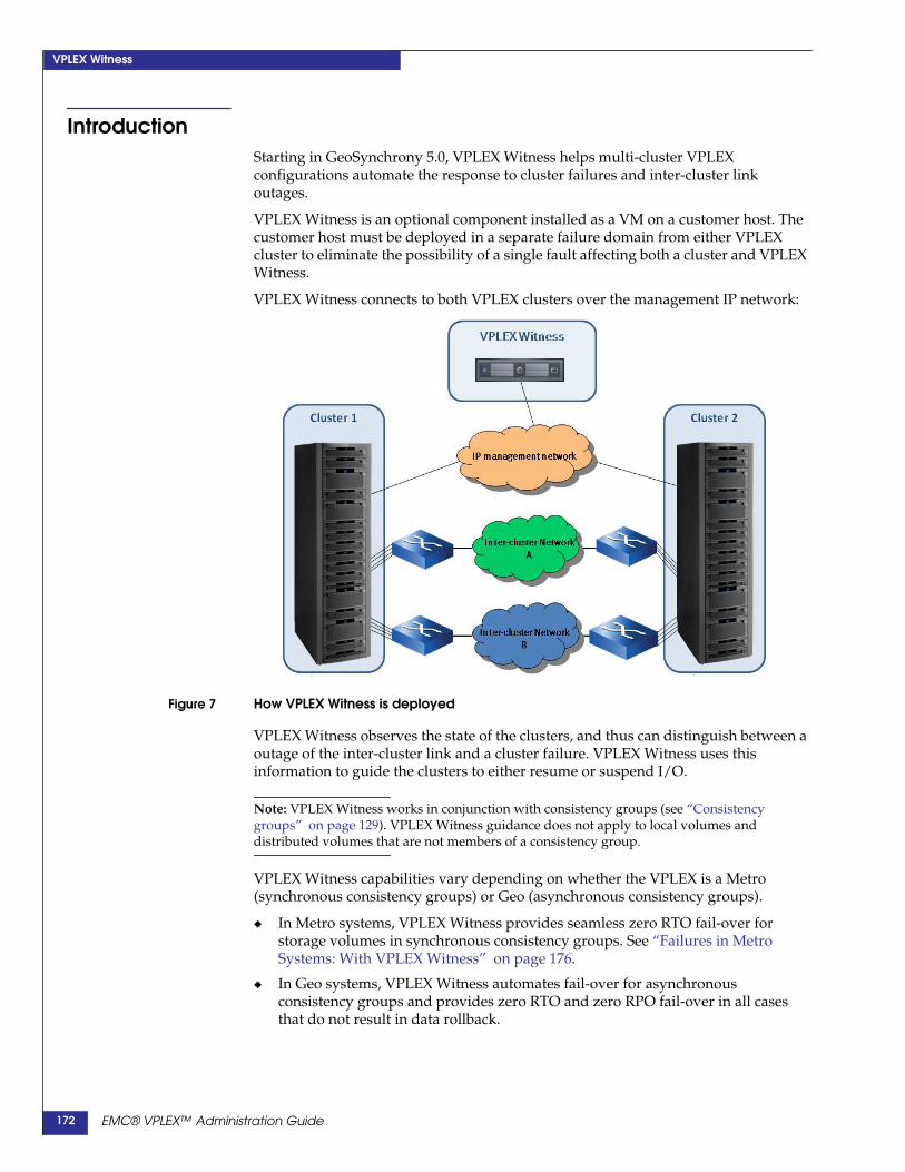
VPLEX Witness
IntroductionStarting in GeoSynchrony 5.0, VPLEX Witness helps multi-cluster VPLEXconfigurations automate the response to cluster failures and inter-cluster linkoutages.
VPLEX Witness is an optional component installed as a VM on a customer host. Thecustomer host must be deployed in a separate failure domain from either VPLEXcluster to eliminate the possibility of a single fault affecting both a cluster and VPLEXWitness.
VPLEX Witness connects to both VPLEX clusters over the management IP network:
Figure 7 How VPLEX Witness is deployed
VPLEX Witness observes the state of the clusters, and thus can distinguish between aoutage of the inter-cluster link and a cluster failure. VPLEX Witness uses thisinformation to guide the clusters to either resume or suspend I/O.
Note: VPLEX Witness works in conjunction with consistency groups (see “Consistencygroups” on page 129). VPLEX Witness guidance does not apply to local volumes anddistributed volumes that are not members of a consistency group.
VPLEX Witness capabilities vary depending on whether the VPLEX is a Metro(synchronous consistency groups) or Geo (asynchronous consistency groups).
◆ In Metro systems, VPLEX Witness provides seamless zero RTO fail-over forstorage volumes in synchronous consistency groups. See “Failures in MetroSystems: With VPLEX Witness” on page 176.
◆ In Geo systems, VPLEX Witness automates fail-over for asynchronousconsistency groups and provides zero RTO and zero RPO fail-over in all casesthat do not result in data rollback.
EMC® VPLEX™ Administration Guide172

VPLEX Witness
Related Information Additional information, including procedures to install, configure, enable, anddisable VPLEX Witness is published in the following EMC documents:
Handling failures when VPLEX Witness is not deployed: detach rulesWhen VPLEX Witness is not deployed, detach rules determine at which cluster I/Ocontinues during a cluster failure or inter-cluster link outage.
Note: The cluster on which I/O continues during a failure is called the preferred cluster.
VPLEX uses two levels of detach rules to determine which cluster is preferred: detachrules associated with individual distributed devices, and detach rules associated withconsistency groups.
Detach rules associated with distributed devices - Every distributed device musthave a detach rule. There are two device-level detach rules:
• cluster-1-detaches
Cluster-1 is the preferred cluster. During a cluster failure or inter-cluster linkoutage, cluster-1 continues I/O and cluster-2 suspends I/O.
• cluster-2-detaches
Cluster-2 is the preferred cluster. During a cluster failure or inter-cluster linkoutage, cluster-2 continues I/O and cluster-1 suspends I/O.
VPLEX Witness does not override device-level detach rules.
Detach rules associated with consistency groups - Every consistency group has adetach rule that applies to all member devices in the consistency group. If adistributed device is a member of a consistency group, the detach rule of theconsistency group overrides the detach rule configured for the device.
There are three consistency group detach rules.
• active-cluster-wins
This detach rule applies only to asynchronous consistency groups (VPLEXGeo configurations).
If one cluster was active and one was passive at the time of the failure, theactive cluster is preferred. See “When a cluster is active vs. passive” onpage 143.
The consistency group’s “auto-resume-at-loser” property must be set to truefor the active-cluster-wins rule to work.
• winner cluster-name delay seconds
This detach rule applies only to synchronous consistency groups (VPLEXMetro configurations).
Information Reference
Commands to enable/disable/display VPLEX Witness EMC VPLEX CLI Guide
Consistency groups Chapter 8, “Consistency groups,”
Procedures to install/configure VPLEX Witness EMC VPLEX Procedure Generator
Procedures to troubleshoot VPLEX Witness EMC VPLEX Procedure Generator
EMC® VPLEX™ Administration Guide 173

VPLEX Witness
The cluster specified by cluster-name is declared the preferred cluster if afailure lasts more than the number of seconds specified by seconds.
• no-automatic-winner
Consistency groups with this detach rules are not guided by VPLEX Witness.
The consistency group does not select the preferred cluster. The detach rules ofthe member devices determine the preferred cluster for that device.
Manual intervention may be required to restart I/O on the suspended cluster.
EMC® VPLEX™ Administration Guide174

VPLEX Witness
Failures in Metro systems without/with VPLEX WitnessVPLEX Metro configurations (synchronous consistency groups) have two consistencygroup level detach rules:
◆ “winner cluster-name delay seconds”
◆ “no-automatic-winner”
VPLEX Witness does not guide consistency groups with the “no-automatic-winner”detach rule. The remainder of this discussion applies only to synchronousconsistency groups with the “winner cluster-name delay seconds” detach rule.
Synchronous consistency groups use write-through caching. Host writes to adistributed volume are acknowledged back to the host only after the data is written tothe back-end storage at both VPLEX clusters.
Failures in Metro Systems: Without VPLEX WitnessIn Figure 8, the “winner cluster-name delay seconds” detach rule designates cluster-1as the preferred cluster. That is, during an inter-cluster link outage or a cluster failure,I/O to the device leg at cluster-1 continues, and I/O to the device leg at cluster-2 issuspended.
Three common types of failures that illustrate how VPLEX responds without ClusterWitness are described below:.
Figure 8 Failure scenarios in VPLEX Metro configurations without VPLEX Witness
Scenario 1 - Inter-cluster link outage. Both of the dual links between the clusters havean outage. Also known as a “cluster partition”.
• The preferred cluster (cluster-1) continues I/O
• Cluster-2 suspends I/O
The existing detach rules are sufficient to prevent data unavailability. Writes atcluster-1 are logged. When the inter-cluster link is restored, a log rebuild copiesonly the logged changes to resynchronize the clusters.
Scenario 2 - Cluster-2 fails.
• Cluster-1 (the preferred cluster) continues I/O.
The existing detach rules are sufficient to prevent data unavailability. Volumes areaccessible with no disruptions at cluster-1.
Scenario 1
Cluster 1 Cluster 2
Scenario 2 Scenario 3
Cluster 1 Cluster 2 Cluster 1 Cluster 2
EMC® VPLEX™ Administration Guide 175

VPLEX Witness
Writes at cluster-1 are logged. When cluster-2 is restored, and rejoins cluster-1, alog rebuild copies only the logged changes to resynchronize cluster-2.
Scenario 3 - Cluster-1 (the preferred cluster) fails.
• Cluster-2 suspends I/O (data unavailability)
VPLEX cannot automatically recover from this failure and suspends I/O at theonly operating cluster.
When the failure is repaired, recovery may require manual intervention tore-enable I/O on cluster-2.
VPLEX Witness addresses Scenario 3, where the preferred cluster fails, and theun-preferred cluster cannot continue I/O due to the configured detach rule-set.
Failures in Metro Systems: With VPLEX WitnessWhen VPLEX Witness is deployed in a VPLEX Metro configuration, failure of thepreferred cluster (Scenario 3) does not result in data unavailability for distributeddevices that are members of (synchronous) consistency groups.
Figure 9 VPLEX Metro - preferred cluster fails
Instead, VPLEX Witness guides the surviving cluster to continue I/O, despite it’sdesignation as the non-preferred cluster. I/O continues to all distributed volumes inall synchronous consistency groups that do not have the “no-automatic-winner”detach rule.
Host applications continue I/O on the surviving cluster without any manualintervention.
When the preferred cluster fails in a Metro configuration, VPLEX Witness providesseamless zero RTO failover to the surviving cluster.
VPLEX Witness failures The VPLEX Witness Server VM connects to the VPLEX clusters over the managementIP network. The deployment of VPLEX Witness adds a point of failure to the VPLEXdeployment.
This section describes the impact of failures of the VPLEX Witness Server VM and thenetwork connections between the VM and the clusters.
EMC® VPLEX™ Administration Guide176

VPLEX Witness
Failures of the connections between cluster and the VPLEX Witness VM are managedas follows:
Figure 10 VPLEX Witness to VPLEX cluster connection failures
Local Cluster Isolation - The preferred cluster loses contact with both the remotecluster and VPLEX Witness.
• The preferred cluster cannot receive guidance from VPLEX Witness andsuspends I/O.
• VPLEX Witness guides the non-preferred cluster to continue I/O.
Remote Cluster Isolation - The preferred cluster loses contact with the remote clusterand the non-preferred cluster loses contact with the VPLEX Witness. The preferredcluster is connected to VPLEX Witness.
• The preferred cluster continues I/O as it is still in contact with the VPLEXWitness.
• The non-preferred cluster suspends I/O, as it is neither in contact with theother cluster, nor can it receive guidance from VPLEX Witness.
Inter-Cluster Partition - Both clusters lose contact with each other, but still haveaccess to the VPLEX Witness. VPLEX Witness preserves the detach rule failurebehaviors:
• I/O continues on the preferred cluster.
• If the preferred cluster can not proceed because it has not fully synchronized,the cluster suspends I/O.
Loss of Contact with VPLEX Witness - The clusters are still in contact with eachother, but one of the clusters (either preferred or non-preferred) has lost contact withVPLEX Witness.
• There is no change in I/O.
• The cluster that lost connectivity with VPLEX Witness sends a call-homenotification.
I/O Contin
uesI/O Suspends
Local Cluster Isolation
Cluster 2
VPLEX Witness
Cluster 1
I/O SuspendsI/O Continues
Remote Cluster Isolation
Cluster 2
VPLEX Witness
Cluster 1
Inter Cluster Partition
Cluster 2
VPLEX Witness
Cluster 1
I/O Contin
uesI/O Continues
Loss of Contact with VPLEX Witness
Cluster 2
VPLEX Witness
Cluster 1
EMC® VPLEX™ Administration Guide 177

VPLEX Witness
Failures in Geo systems without/with VPLEX WitnessIn VPLEX Geo configurations (asynchronous consistency groups) the two detachrules that apply are:
◆ “active-cluster-wins”
◆ “no-automatic-winner”
This discussion applies only to asynchronous consistency groups with the“active-cluster-wins” detach rule.
Failures in VPLEX Geo systems - Without VPLEX WitnessFailures behaviors in VPLEX Geo configurations vary depending on whether I/Owas occurring at one or both legs of a distributed device when the failure occurred.
This section describes a selection of failures when I/O is occurring at only one leg(active/passive) and both legs (active/active). See “When a cluster is active vs.passive” on page 143.
Active/passive In an active/passive configuration, hosts at only one cluster write to legs ofdistributed volumes located at both clusters. Failures in active/passive scenarios arehandled as follows:
◆ Entire engine on the passive cluster fails - No loss of data or access. If eitherdirector in the failed engine had deltas in “commit” or “exchange”, part of thedelta is lost at the passive cluster. These deltas are re-copied across theinter-cluster link from the active cluster.
◆ Entire engine on the active cluster fails - All data in open, closed, andexchanging deltas is discarded. I/O is suspended at both clusters. Manualintervention is required (resume-after-data-loss-failure command) to roll backthe data image to the last committed delta (the last consistent point in time).
◆ Passive cluster fails - No loss of data or access. I/O continues on the activecluster. All writes are logged. When the passive cluster is restored, and rejoins, alog rebuild copies only the logged changes to resynchronize the passive cluster.
◆ Active cluster fails - Dirty data is lost, and the volumes are suspended at thepassive cluster. Hosts at the active cluster experience a DU.
All writes at the passive cluster are logged. When the active cluster is restoredand rejoins VPLEX, a log rebuild copies only changes to the active cluster.
Users can failover applications to the passive cluster using the choose-winnerand resume-after-rollback commands.
Alternatively, users can wait for the failed cluster to be restored. When the failedcluster is restored and rejoins, VPLEX recognizes that the failed cluster has lostdata and rolls back to the last committed delta (last time consistent image). Theuser must manually re-enable I/O at the recovered cluster (resume-at-losercommand).
◆ Inter-cluster link outage - No loss of data or access. I/O continues on the activecluster. All I/O is logged. On the passive cluster, local volumes are accessible tolocal hosts. When the inter-cluster link is restored, a log rebuild copies only thelogged changes to resynchronize the passive cluster.
Active/active In an active/active configuration, hosts at both clusters write to legs of distributedvolumes at both clusters. Failures in active/active scenarios are handled as follows:
EMC® VPLEX™ Administration Guide178

VPLEX Witness
◆ Entire engine on the either cluster fails - All data in open, closed, andexchanging deltas is discarded. I/O is suspended at both clusters. Manualintervention (resume-after-data-loss-failure command), is required to roll backthe data image to the last committed delta, which is the last consistent point intime.
◆ Either cluster fails - All data in open, closed, and exchanging deltas is discarded.I/O to volumes is suspended at both clusters. All writes are logged at thesurviving cluster. When the failed cluster is restored and rejoins, a log rebuildcopies only changes to the restored cluster.
Users can failover applications to the surviving cluster using the choose-winnerand resume-after-rollback commands. VPLEX rolls back the data image to theend of the last committed delta (last consistent point in time). Applications mustbe restarted or rolled back.
Users can wait for the failed cluster to be restored. When the failed cluster isrestored and rejoins, VPLEX recognizes that the failed cluster has lost data androlls back to the last committed delta (last time consistent image). The user mustmanually re-enable I/O at the recovered cluster (resume-at-loser command).
◆ Inter-cluster link outage - I/O suspended at both clusters. I/O at both clusters islogged.
Users can wait for the network outage to resolve. When the inter-cluster link isrestored, a log rebuild copies only the logged changes to resynchronize theclusters.
Alternatively, users can manually choose a cluster to continue I/O. Manualintervention (resume-after-data-loss-failure command) rolls back the data imageto the last committed delta, which is the last consistent point in time. Applicationsare then re-started.
Multiple failures in VPLEX Geo systemsDuring recovery, a failed director's dirty cache is recovered from its protectionpartner and re-protected. If portions of committed and exchanged deltas have beenlost, they are retrieved from the other cluster.
Exchanging deltas are not replicated within the cluster. Thus, a cluster failure cancause a loss of parts of deltas at that cluster. If the surviving cluster remains healthy, acomplete copy of the deltas are at the other cluster.
These recovery operations create scenarios where an additional failure can result indata loss or data unavailability.
This section describes how multiple failures are handled.
◆ Failed director's protection partner also fails - If the failed director's protectionpartner fails before dirty cache recovery completes, VPLEX has lost data.
This is both a DU and a DL.
Recovery from an external backup is required.
◆ Inter-cluster link outage during director failure recovery - A single directorfailure followed by a inter-cluster link outage before failure recovery of themissing portions of the commit delta are copied.
The cluster with the failed director did not complete committing the delta and theimage on backend storage is not a time consistent image.
EMC® VPLEX™ Administration Guide 179

VPLEX Witness
If a detach rule or user command causes the unhealthy cluster to become a winnerin this state, the affected consistency groups stay suspended at that cluster.
If the unhealthy cluster (the one at which the original failure occurred) is notdetached, the user may:
• Wait for the network to be restored.
No data is lost.
• Accept a data rollback and resume I/O at the other, healthy cluster.
◆ Multiple BE storage volume failures after a inter-cluster link outage - Thisscenario occurs when a cluster is declared preferred during a inter-cluster linkoutage. When the link recovers, the preferred cluster updates the other cluster(logging rebuild). If the target disks on the cluster being updated fail, theconsistency group suspends.
Recovery from an external backup is required.
Data loss failure mode (DLFM)In some extremely rare system-wide multi-failure scenarios the system may enterData Loss Failure Mode, including data loss and potential loss of crash consistency ondisk in both clusters.
This state applies to individual asynchronous consistency groups; that is, while oneasynchronous consistency group may be in Data Loss Failure Mode, others on thesame VPLEX Geo system may be unaffected.
Best practices toavoid DLFM
To avoid DLFM, follow these best practices when configuring your system:
◆ Mirror local DR1 legs to two local arrays with a RAID-1. Local mirrors minimizethe risk of back-end visibility issues during array failures
◆ Follow best practices for high availability when deploying VPLEX Geoconfigurations. Refer to the VPLEX Product Guide.
Recover from DLFM Refer to the troubleshooting procedure for recovering from DLFM in the VPLEXProcedure Generator.
Note: VPLEX Witness has no impact on distributed volumes in asynchronous consistencygroups configured with the no-automatic-winner rule. In that case, manual intervention isrequired in the presence of any failure scenario.
Failures in Geo Systems: With VPLEX WitnessThe value of the VPLEX Witness is different in VPLEX Geo configurations than it is inVPLEX Metro configurations. The value also varies depending on the release ofGeoSynchrony.
The following sections describe the value of VPLEX Witness in Geo configurations forGeoSynchrony releases 5.0.1 and 5.1.
GeoSynchrony 5.0.1 For systems running GeoSynchrony 5.0.1, clusters in Geo configurations do notcomply with VPLEX Witness guidance. Instead the clusters operate according to thedetach rules applied to each asynchronous consistency group.
EMC® VPLEX™ Administration Guide180

VPLEX Witness
Information displayed in the VPLEX Witness CLI context helps to determine thenature of a failure (cluster failure or inter-cluster link outage). Administrators can usethis information to make manual fail-over decisions.
The following example shows output of ll components commands when cluster-2has failed:
VPlexcli:/cluster-witness> ll components//cluster-witness/components:Name ID Admin State Operational State Mgmt Connectivity---------- -- ----------- ------------------------------- -----------------cluster-1 1 enabled remote-cluster-isolated-or-dead okcluster-2 2 unknown - failedserver - enabled cluster-unreachable ok
VPlexcli:/cluster-witness> ll components/*/cluster-witness/components/cluster-1:Name Value----------------------- ------------------------------------------------------admin-state enableddiagnostic WARNING: Current state of cluster-1 is
remote-cluster-isolated-or-dead (last state change: 0days, 15 secs ago; last message from server: 0 days, 0secs ago.)
id 1management-connectivity okoperational-state remote-cluster-isolated-or-dead
/cluster-witness/components/cluster-2:Name Value----------------------- ------------------------------------------------------admin-state unknowndiagnostic WARNING: Cannot establish connectivity with cluster-2
to query diagnostic information.id 2management-connectivity failedoperational-state -
/cluster-witness/components/server:Name Value----------------------- ------------------------------------------------------admin-state enableddiagnostic WARNING: Current state is cluster-unreachable (last
state change: 0 days, 15 secs ago.) (last time ofcommunication with cluster-1: 0 days, 0 secs ago.)(last time of communication with cluster-2: 0 days,34 secs ago.)
id -management-connectivity okoperational-state cluster-unreachable
GeoSynchrony 5.1 For VPLEX Geo systems running GeoSynchrony 5.1, VPLEX Witness automates theresponse to failure scenarios that do not require data rollback
Manual intervention is required if data rollback is needed.
Preferred cluster failsThe value of VPLEX Witness when the preferred cluster fails varies depending onwhether data rollback is required.
◆ No data rollback is required - VPLEX Witness guides the surviving cluster toallow I/O to all distributed volumes in all asynchronous consistency groupsconfigured with the “active-cluster-wins” detach rule.
I/O continues at the non-preferred cluster.
EMC® VPLEX™ Administration Guide 181

VPLEX Witness
If no rollback is required, VPLEX Witness automates failover with zero RTO andzero RPO.
◆ Rollback is required - If data rollback is required, all asynchronous consistencygroups suspend I/O regardless of VPLEX Witness guidance, and thepre-configured rule set.
Manual intervention is required to force the rollback in order to change thecurrent data image to the last consistent image preserved on disk.
The application may need to be manually restarted to ensure that it does not usedata that is still in the application’s cache, but has been discarded by VPLEX.
Inter-cluster link outageIn the event of a inter-cluster link outage, VPLEX Witness guides the preferred clusterto continue I/O. Similar to failure of the preferred cluster, the value of VPLEXWitness varies depending on whether data rollback is required.
◆ No data rollback is required - VPLEX Witness guides the preferred cluster tocontinue I/O to all distributed volumes in all asynchronous consistency groupsconfigured with the “active-cluster-wins” detach rule.
I/O is suspended at the non-preferred cluster.
VPLEX Witness automates failover with zero RTO and zero RPO.
◆ Rollback is required - If data rollback is required, all asynchronous consistencygroups suspend I/O regardless of VPLEX Witness guidance, and theirpre-configured rule set.
Manual intervention is required to force the rollback in order to change thecurrent data image to the last consistent image preserved on disk, and to restartI/O to the suspended consistency groups.
The application may need to be manually restarted to ensure that it does not usedata that is still in the application’s cache, but has been discarded by VPLEX.
EMC® VPLEX™ Administration Guide182

VPLEX Witness
Install, enable, and manage VPLEX WitnessVPLEX Witness is to designed to improve availability in your storage network.
You should carefully consider how you install and enable VPLEX Witness.
Installation considerationsIt is important to deploy the VPLEX Witness server VM in a separate failure domainthan either cluster.
A failure domain is a set of entities effected by the same set of faults. The scope of thefailure domain depends on the set of fault scenarios that can be tolerated in a givenenvironment. For example:
◆ If the two clusters are deployed on different floors of the same data center, deploythe VPLEX Witness Server VM on a separate floor.
◆ If the two clusters are deployed in two different data centers, deploy the VPLEXWitness Server VM in the third data center.
WARNING
If the VPLEX Witness Server VM cannot be deployed in a failure domain independentfrom either of VPLEX cluster, VPLEX Witness should not be installed.
The following are additional recommendations for installing and deploying VPLEXWitness:
◆ Connect the Cluster Witness Server VM to a power source that is independent ofpower sources supplying power to the clusters.
◆ Connect the Cluster Witness Server VM to an Uninterruptable Power Supply(UPS).
◆ Enable the BIOS Virtualization Technology (VT) extension on the ESX host wherethe Cluster Witness Server VM is installed to ensure performance of the ClusterWitness Server VM.
◆ Secure access the ESX host server using a password.
◆ The IP Management network (connecting the cluster management servers and theCluster Witness Server VM) must be physically separate from the inter-clusternetworks.
◆ Latency in the network between Cluster Witness Server VM and the clustermanagement servers should not exceed 1 second (round trip).
Complete instructions to install and deploy the VPLEX Witness Server VM areavailable in the VPLEX Procedure Generator.
CLI contextThe VPLEX Witness software includes a client on each of the VPLEX clusters. VPLEXWitness does not appear in the CLI until the client has been configured.
Complete instructions to configure the VPLEX Witness client are available in theVPLEX Procedure Generator.
Descriptions of the CLI commands to configure the VPLEX Witness client areavailable in the VPLEX CLI Guide.
EMC® VPLEX™ Administration Guide 183

VPLEX Witness
Once VPLEX Witness is installed and configured on the clusters, a CLI context called“cluster-witness” appears in the CLI context tree:
VPlexcli:/cluster-witness> lsAttributes:Name Value------------- -------------admin-state enabledprivate-ip-address 128.221.254.3public-ip-address 10.31.25.45
Contexts:components
Enable/disable VPLEX Witness clientOnce VPLEX Witness client is configured on the clusters, the cluster-witness contextis added to the CLI context tree, and you can enable and disable the client.
Enable the VPLEX Witness client on the clusters to provide guidance.
Disable the VPLEX Witness client on the clusters when:
◆ The VPLEX Witness Server VM fails, and is not expected to be restored quickly.
◆ Connectivity between both clusters and the VPLEX Witness Server VM fails, andis not expected to be restored quickly.
There is no impact on I/O to distributed volumes. Both clusters send a call-homenotification to indicate that they have lost connectivity with the Cluster WitnessServer. However, an additional failure (cluster failure or inter-cluster link outage)may result in a Data Unavailability.
CAUTION!When you disable the VPLEX Witness client on the clusters, all distributedvolumes in consistency groups use their consistency group-level detach rules todetermine which cluster is preferred.
Complete instructions to enable/disable the VPLEX Witness client are available in theVPLEX Procedure Generator.
Descriptions of the CLI commands to enable/disable the VPLEX Witness client areavailable in the VPLEX CLI Guide.
Renew the VPLEX Witness security certificateWhen VPLEX Witness is installed, a VPLEX Witness host security certificate iscreated.
All types of security certificates expire and must be periodically renewed. Hostcertificates (including the VPLEX Witness host security certificate) must be renewedevery 2 years.
Complete instructions to renew the VPLEX Witness security certificate are availablein the VPLEX Procedure Generator.
Descriptions of the CLI commands to renew the VPLEX Witness security certificateare available in the VPLEX CLI Guide.
EMC® VPLEX™ Administration Guide184

VPLEX Witness
VPLEX Witness operationThis section describes the output of CLI commands during normal operations and invarious failure states:
◆ “Normal operation”
◆ “Single failures (no data unavailability)”
◆ “Dual failures (no data unavailability)”
◆ “Single failures (data unavailability at one cluster)”
◆ “Dual failure (cluster isolation/DU at one cluster)”
Use the ls command in /cluster-witness context to display the state and IP addresses.
Use the ll components/ command in /cluster-witness context to display status ofcomponents (VPLEX clusters and the VPLEX Witness Server).
Use the ll components/* command in /cluster-witness context to display detailedinformation (including diagnostics)
Table 9 lists the fields in the output of these commands.
Table 9 VPLEX Witness display fields (1 of 2)
Field Description
Name Name of component,For VPLEX clusters – name assigned to cluster.For VPLEX Witness server – “server”.
id ID of a VPLEX cluster.Always blank “-“ for Witness server.
admin state Identifies whether VPLEX Witness is enabled/disabled. Valid values are:enabled - VPLEX Witness functionality is enabled on this component.disabled - VPLEX Witness functionality is disabled on this component.inconsistent - All Cluster Witness components are reachable over the management network but somecomponents report their administrative state as disabled while others report it as enabled. This is a rarestate which may result failure during enabling or disabling.unknown - This component is not reachable and its administrative state cannot be determined.
private-ip-address Private IP address of the Cluster Witness Server VM used for cluster witness-specific traffic.
public-ip-address Public IP address of the Cluster Witness Server VM used as an endpoint of the IPsec tunnel.
diagnostic String generated by CLI based on the analysis of the data and state information reported by thecorresponding component.WARNING: Cannot establish connectivity with Cluster Witness Server to query diagnosticinformation. - Cluster Witness Server or one of the clusters is unreachable.Local cluster-x hasn't yet established connectivity with the server - The cluster has neverconnected to Cluster Witness Server.Remote cluster-x hasn't yet established connectivity with the server - The cluster has neverconnected to Cluster Witness Server.Cluster-x has been out of touch from the server for X days, Y secs - Cluster Witness Server has notreceived messages from a given cluster for longer than 60 seconds.Cluster witness server has been out of touch for X days, Y secs - Either cluster has not receivedmessages from Cluster Witness Server for longer than 60 seconds.Cluster Witness is not enabled on component-X, so no diagnostic information is available -Cluster Witness Server or either of the clusters is disabled.
EMC® VPLEX™ Administration Guide 185
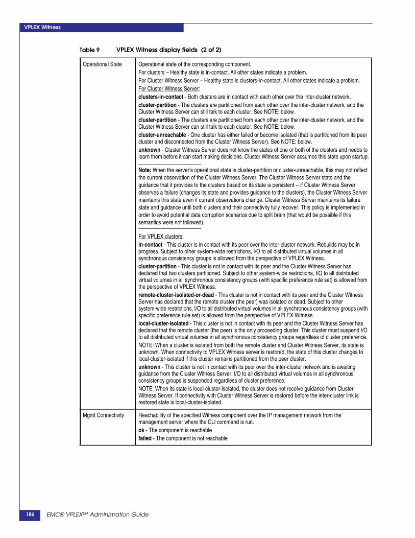
VPLEX Witness
Operational State Operational state of the corresponding component.For clusters – Healthy state is in-contact. All other states indicate a problem.For Cluster Witness Server – Healthy state is clusters-in-contact. All other states indicate a problem.For Cluster Witness Server:clusters-in-contact - Both clusters are in contact with each other over the inter-cluster network.cluster-partition - The clusters are partitioned from each other over the inter-cluster network, and theCluster Witness Server can still talk to each cluster. See NOTE: below.cluster-partition - The clusters are partitioned from each other over the inter-cluster network, and theCluster Witness Server can still talk to each cluster. See NOTE: below.cluster-unreachable - One cluster has either failed or become isolated (that is partitioned from its peercluster and disconnected from the Cluster Witness Server). See NOTE: below.unknown - Cluster Witness Server does not know the states of one or both of the clusters and needs tolearn them before it can start making decisions. Cluster Witness Server assumes this state upon startup.
Note: When the server’s operational state is cluster-partition or cluster-unreachable, this may not reflectthe current observation of the Cluster Witness Server. The Cluster Witness Server state and theguidance that it provides to the clusters based on its state is persistent -- if Cluster Witness Serverobserves a failure (changes its state and provides guidance to the clusters), the Cluster Witness Servermaintains this state even if current observations change. Cluster Witness Server maintains its failurestate and guidance until both clusters and their connectivity fully recover. This policy is implemented inorder to avoid potential data corruption scenarios due to split brain (that would be possible if thissemantics were not followed).
For VPLEX clusters:in-contact - This cluster is in contact with its peer over the inter-cluster network. Rebuilds may be inprogress. Subject to other system-wide restrictions, I/O to all distributed virtual volumes in allsynchronous consistency groups is allowed from the perspective of VPLEX Witness.cluster-partition - This cluster is not in contact with its peer and the Cluster Witness Server hasdeclared that two clusters partitioned. Subject to other system-wide restrictions, I/O to all distributedvirtual volumes in all synchronous consistency groups (with specific preference rule set) is allowed fromthe perspective of VPLEX Witness.remote-cluster-isolated-or-dead - This cluster is not in contact with its peer and the Cluster WitnessServer has declared that the remote cluster (the peer) was isolated or dead. Subject to othersystem-wide restrictions, I/O to all distributed virtual volumes in all synchronous consistency groups (withspecific preference rule set) is allowed from the perspective of VPLEX Witness.local-cluster-isolated - This cluster is not in contact with its peer and the Cluster Witness Server hasdeclared that the remote cluster (the peer) is the only proceeding cluster. This cluster must suspend I/Oto all distributed virtual volumes in all synchronous consistency groups regardless of cluster preference.NOTE: When a cluster is isolated from both the remote cluster and Cluster Witness Server, its state isunknown. When connectivity to VPLEX Witness server is restored, the state of this cluster changes tolocal-cluster-isolated if this cluster remains partitioned from the peer cluster.unknown - This cluster is not in contact with its peer over the inter-cluster network and is awaitingguidance from the Cluster Witness Server. I/O to all distributed virtual volumes in all synchronousconsistency groups is suspended regardless of cluster preference.NOTE: When its state is local-cluster-isolated, the cluster does not receive guidance from ClusterWitness Server. If connectivity with Cluster Witness Server is restored before the inter-cluster link isrestored state is local-cluster-isolated.
Mgmt Connectivity Reachability of the specified Witness component over the IP management network from themanagement server where the CLI command is run.ok - The component is reachablefailed - The component is not reachable
Table 9 VPLEX Witness display fields (2 of 2)
EMC® VPLEX™ Administration Guide186

VPLEX Witness
Normal operationDuring normal operation (no failures), the output of display commands from thecluster-witness CLI context are as follows:
VPlexcli:/cluster-witness> lsAttributes:Name Value------------- -------------admin-state enabledprivate-ip-address 128.221.254.3public-ip-address 10.31.25.45
Contexts:components
VPlexcli:/cluster-witness> ll components//cluster-witness/components:Name ID Admin State Operational State Mgmt Connectivity---------- -- ----------- ------------------- -----------------cluster-1 1 enabled in-contact okcluster-2 2 enabled in-contact okserver - enabled clusters-in-contact ok
VPlexcli:/cluster-witness> ll components/*/cluster-witness/components/cluster-1:Name Value----------------------- ------------------------------------------------------admin-state enableddiagnostic INFO: Current state of cluster-1 is in-contact (last
state change: 0 days, 13056 secs ago; last messagefrom server: 0 days, 0 secs ago.)
id 1management-connectivity okoperational-state in-contact
/cluster-witness/components/cluster-2:Name Value----------------------- ------------------------------------------------------admin-state enableddiagnostic INFO: Current state of cluster-2 is in-contact (last
state change: 0 days, 13056 secs ago; last messagefrom server: 0 days, 0 secs ago.)
id 2management-connectivity okoperational-state in-contact
/cluster-witness/components/server:Name Value----------------------- ------------------------------------------------------admin-state enableddiagnostic INFO: Current state is clusters-in-contact (last state
change: 0 days, 13056 secs ago.) (last time ofcommunication with cluster-2: 0 days, 0 secs ago.)(last time of communication with cluster-1: 0 days, 0secs ago.)
id -management-connectivity okoperational-state clusters-in-contact
Single failures (no data unavailability)Single failures that do not impact I/O to distributed volumes include:
EMC® VPLEX™ Administration Guide 187
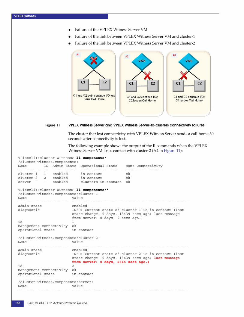
VPLEX Witness
◆ Failure of the VPLEX Witness Server VM
◆ Failure of the link between VPLEX Witness Server VM and cluster-1
◆ Failure of the link between VPLEX Witness Server VM and cluster-2
Figure 11 VPLEX Witness Server and VPLEX Witness Server-to-clusters connectivity failures
The cluster that lost connectivity with VPLEX Witness Server sends a call-home 30seconds after connectivity is lost.
The following example shows the output of the ll commands when the VPLEXWitness Server VM loses contact with cluster-2 (A2 in Figure 11):
VPlexcli:/cluster-witness> ll components//cluster-witness/components:Name ID Admin State Operational State Mgmt Connectivity---------- -- ----------- ------------------- -----------------cluster-1 1 enabled in-contact okcluster-2 2 enabled in-contact okserver - enabled clusters-in-contact ok
VPlexcli:/cluster-witness> ll components/*/cluster-witness/components/cluster-1:Name Value----------------------- ------------------------------------------------------admin-state enableddiagnostic INFO: Current state of cluster-1 is in-contact (last
state change: 0 days, 13439 secs ago; last messagefrom server: 0 days, 0 secs ago.)
id 1management-connectivity okoperational-state in-contact
/cluster-witness/components/cluster-2:Name Value----------------------- ------------------------------------------------------admin-state enableddiagnostic INFO: Current state of cluster-2 is in-contact (last
state change: 0 days, 13439 secs ago; last messagefrom server: 0 days, 2315 secs ago.)
id 2management-connectivity okoperational-state in-contact
/cluster-witness/components/server:Name Value----------------------- ------------------------------------------------------
EMC® VPLEX™ Administration Guide188

VPLEX Witness
admin-state enableddiagnostic INFO: Current state is clusters-in-contact (last state
change: 0 days, 13439 secs ago.) (last time ofcommunication with cluster-1: 0 days, 0 secs ago.)(last time of communication with cluster-2: 0 days,2315 secs ago.)
id -management-connectivity okoperational-state clusters-in-contact
Dual failures (no data unavailability)The failure of both links between VPLEX Witness Server VM and cluster-1 andcluster-2 also does not impact I/O to distributed volumes.
Figure 12 Dual VPLEX Witness Server-to-clusters connectivity failures
Both clusters send a call-home indicating that they have lost connectivity with theCluster Witness Server.
Note: If an additional inter-cluster link or cluster failure occurs, the system is at risk of dataunavailability.
The following example shows the output of the ll commands when the VPLEXWitness Server VM loses contact with both clusters:
Note: The cluster-witness CLI context on cluster-2 shows the same loss of connectivity to theCSWS.
VPlexcli:/cluster-witness> ll components//cluster-witness/components:Name ID Admin State Operational State Mgmt Connectivity---------- -- ----------- ----------------- -----------------cluster-1 1 enabled in-contact okcluster-2 2 enabled in-contact okserver - unknown - failed
VPlexcli:/cluster-witness> ll components/*/cluster-witness/components/cluster-1:Name Value----------------------- ------------------------------------------------------
EMC® VPLEX™ Administration Guide 189

VPLEX Witness
admin-state enableddiagnostic WARNING: Current state of cluster-1 is in-contact
(last state change: 0 days, 94 secs ago; last messagefrom server: 0 days, 34 secs ago.)
id 1management-connectivity okoperational-state in-contact
/cluster-witness/components/cluster-2:Name Value----------------------- ------------------------------------------------------admin-state enableddiagnostic WARNING: Current state of cluster-2 is in-contact
(last state change: 0 days, 94 secs ago; last messagefrom server: 0 days, 34 secs ago.)
id 2management-connectivity okoperational-state in-contact
/cluster-witness/components/server:Name Value----------------------- ------------------------------------------------------admin-state unknowndiagnostic WARNING: Cannot establish connectivity with Cluster
Witness Server to query diagnostic information.id -management-connectivity failedoperational-state -
Single failures (data unavailability at one cluster)Single failures that impact I/O to distributed volumes include:
◆ Failure of the inter-cluster link
◆ Failure of cluster-1
◆ Failure of cluster-2
Figure 13 Single failures; inter-cluster link or one cluster resulting in data unavailability
When a single failure occurs, each cluster receives guidance from VPLEX WitnessServer and sends a call-home indicating the guidance and changes its internal state.
The following examples show the output of the ls and ll commands following:
EMC® VPLEX™ Administration Guide190
VPLEX Witness
◆ Inter-cluster link failure (B1 in Figure 13)
◆ cluster-1 failure (B3 in in Figure 13)
◆ cluster-2 failure (B2 in Figure 13)
Inter-cluster link failure The following example shows the output of the ll commands following a failure ofthe inter-cluster link (B1 in Figure 13):
VPlexcli:/cluster-witness> ll components//cluster-witness/components:Name ID Admin State Operational State Mgmt Connectivity---------- -- ----------- ----------------- -----------------cluster-1 1 enabled cluster-partition okcluster-2 2 enabled cluster-partition okserver - enabled cluster-partition ok
VPlexcli:/cluster-witness> ll components/*/cluster-witness/components/cluster-1:Name Value----------------------- ------------------------------------------------------admin-state enableddiagnostic WARNING: Current state of cluster-1 is
cluster-partition (last state change: 0 days, 56 secsago; last message from server: 0 days, 0 secs ago.)
id 1management-connectivity okoperational-state cluster-partition
/cluster-witness/components/cluster-2:Name Value----------------------- ------------------------------------------------------admin-state enableddiagnostic WARNING: Current state of cluster-2 is
cluster-partition (last state change: 0 days, 57 secsago; last message from server: 0 days, 0 secs ago.)
id 2management-connectivity okoperational-state cluster-partition
/cluster-witness/components/server:Name Value----------------------- ------------------------------------------------------admin-state enableddiagnostic WARNING: Current state is cluster-partition (last
state change: 0 days, 57 secs ago.) (last time ofcommunication with cluster-1: 0 days, 0 secs ago.)(last time of communication with cluster-2: 0 days, 0secs ago.)
id -management-connectivity okoperational-state cluster-partition
cluster-1 failure The following example shows the output of the ll commands following a failure ofcluster-1 (B3 in Figure 13):
VPlexcli:/cluster-witness> ll components/Name ID Admin State Operational State Mgmt Connectivity--------- -- ----------- ------------------------------- -----------------cluster-1 1 unknown - failedcluster-2 2 enabled remote-cluster-isolated-or-dead okserver - enabled cluster-unreachable ok
VPlexcli:/cluster-witness> ll components/*
EMC® VPLEX™ Administration Guide 191

VPLEX Witness
/cluster-witness/components/cluster-1:Name Value----------------------- ------------------------------------------------------admin-state unknowndiagnostic WARNING: Cannot establish connectivity with cluster-1
to query diagnostic information.id 1management-connectivity failedoperational-state -
/cluster-witness/components/cluster-2:Name Value----------------------- ------------------------------------------------------admin-state enableddiagnostic WARNING: Current state of cluster-2 is
remote-cluster-isolated-or-dead (last state change: 0days, 49 secs ago; last message from server: 0 days, 0secs ago.)
id 2management-connectivity okoperational-state remote-cluster-isolated-or-dead
/cluster-witness/components/server:Name Value----------------------- ------------------------------------------------------admin-state enableddiagnostic WARNING: Current state is cluster-unreachable (last
state change: 0 days, 49 secs ago.) (last time ofcommunication with cluster-2: 0 days, 0 secs ago.)(last time of communication with cluster-1: 0 days, 59secs ago.)
id -management-connectivity okoperational-state cluster-unreachable
cluster-2 failure The following example shows the output of the ll commands following a failure ofcluster-2 (B2 in Figure 13):
VPlexcli:/cluster-witness> ll components//cluster-witness/components:Name ID Admin State Operational State Mgmt Connectivity---------- -- ----------- ------------------------------- -----------------cluster-1 1 enabled remote-cluster-isolated-or-dead okcluster-2 2 unknown - failedserver - enabled cluster-unreachable ok
VPlexcli:/cluster-witness> ll components/*/cluster-witness/components/cluster-1:Name Value----------------------- ------------------------------------------------------admin-state enableddiagnostic WARNING: Current state of cluster-1 is
remote-cluster-isolated-or-dead (last state change: 0days, 15 secs ago; last message from server: 0 days, 0secs ago.)
id 1management-connectivity okoperational-state remote-cluster-isolated-or-dead
/cluster-witness/components/cluster-2:Name Value----------------------- ------------------------------------------------------admin-state unknown
EMC® VPLEX™ Administration Guide192

VPLEX Witness
diagnostic WARNING: Cannot establish connectivity with cluster-2to query diagnostic information.
id 2management-connectivity failedoperational-state -
/cluster-witness/components/server:Name Value----------------------- ------------------------------------------------------admin-state enableddiagnostic WARNING: Current state is cluster-unreachable (last
state change: 0 days, 15 secs ago.) (last time ofcommunication with cluster-1: 0 days, 0 secs ago.)(last time of communication with cluster-2: 0 days,34 secs ago.)
id -management-connectivity okoperational-state cluster-unreachable
Dual failure (cluster isolation/DU at one cluster)Cluster isolation occurs when a cluster loses network connectivity to both its peercluster and Cluster Witness Server. Cluster isolation results in data unavailability onthe isolated cluster.
Cluster Witness server guides the cluster that is still connected to continue I/O.
Figure 14 Cluster isolation resulting in data unavailability
In D1 in Figure 14, cluster-2 is isolated. Cluster Witness Server guides cluster-1 toproceed with I/O on all distributed volumes in all consistency groups regardless ofpreference.
Cluster-2 suspends I/O to all distributed volumes in all consistency groupsregardless of preference.
The following examples show the output of the ll commands:
◆ From cluster-1 when cluster-2 is isolated
◆ From cluster-2 when cluster-2 is isolated
◆ After the VPLEX Witness Server-cluster link is restored
From cluster-1 whencluster-2 is isolated
The following example shows the output of the ll command when cluster-2 isisolated, and cluster-1 remains connected to VPLEX Witness Server (D1 in Figure 14):
EMC® VPLEX™ Administration Guide 193
VPLEX Witness
VPlexcli:/cluster-witness> ll components//cluster-witness/components:Name ID Admin State Operational State Mgmt Connectivity---------- -- ----------- ------------------------------- -----------------cluster-1 1 enabled remote-cluster-isolated-or-dead okcluster-2 2 unknown - failedserver - enabled cluster-unreachable ok
VPlexcli:/cluster-witness> ll components/*/cluster-witness/components/cluster-1:Name Value----------------------- ------------------------------------------------------admin-state enableddiagnostic WARNING: Current state of cluster-1 is
remote-cluster-isolated-or-dead (last state change: 0days, 35 secs ago; last message from server: 0 days, 0secs ago.)
id 1management-connectivity okoperational-state remote-cluster-isolated-or-dead
/cluster-witness/components/cluster-2:Name Value----------------------- ------------------------------------------------------admin-state enableddiagnostic WARNING: Cannot establish connectivity with cluster-2
to query diagnostic information.id 2management-connectivity failedoperational-state -
/cluster-witness/components/server:Name Value----------------------- ------------------------------------------------------admin-state enableddiagnostic WARNING: Current state is cluster-unreachable (last
state change: 0 days, 35 secs ago.) (last time ofcommunication with cluster-1: 0 days, 0 secs ago.)(last time of communication with cluster-2: 0 days,103 secs ago.) Remote cluster has been out of touchfrom the server for 0 days, 103 secs.
id -management-connectivity okoperational-state cluster-unreachable
From cluster-2 whencluster-2 is isolated
CLI output for cluster-2 (which is isolated):
VPlexcli:/cluster-witness> ll components//cluster-witness/components:Name ID Admin State Operational State Mgmt Connectivity---------- -- ----------- ------------------------------- -----------------cluster-1 1 unknown - failedcluster-2 2 unknown - failedserver - unknown - failed
VPlexcli:/cluster-witness> ll components/*/cluster-witness/components/cluster-1:Name Value----------------------- ------------------------------------------------------admin-state unknowndiagnostic WARNING: Cannot establish connectivity with cluster-1
to query diagnostic information.id 1management-connectivity failed
EMC® VPLEX™ Administration Guide194
VPLEX Witness
operational-state -
/cluster-witness/components/cluster-2:Name Value----------------------- ------------------------------------------------------admin-state unknowndiagnostic WARNING: Cannot establish connectivity with cluster-1
to query diagnostic information.id 2management-connectivity failedoperational-state -
/cluster-witness/components/server:Name Value----------------------- ------------------------------------------------------admin-state unknowndiagnostic WARNING: Cannot establish connectivity with Cluster
Witness Server to query diagnostic information.id -management-connectivity failedoperational-state -
After the VPLEX Witness Server-cluster link is restoredIf the link between cluster-2 and VPLEX Witness Server is restored, but theinter-cluster link is NOT restored, output of the ll commands is as follows:
VPlexcli:/cluster-witness> ll components//cluster-witness/components:Name ID Admin State Operational State Mgmt Connectivity---------- -- ----------- ------------------------------- -----------------cluster-1 1 enabled remote-cluster-isolated-or-dead okcluster-2 2 enabled local-cluster-isolated okserver - enabled cluster-unreachable ok
VPlexcli:/cluster-witness> ll components/*/cluster-witness/components/cluster-1:Name Value----------------------- ------------------------------------------------------admin-state enableddiagnostic WARNING: Current state of cluster-1 is
remote-cluster-isolated-or-dead (last state change: 0days, 357 secs ago; last message from server: 0 days,0 secs ago.)
id 1management-connectivity okoperational-state remote-cluster-isolated-or-dead
/cluster-witness/components/cluster-2:Name Value----------------------- ------------------------------------------------------admin-state enableddiagnostic WARNING: Current state of cluster-2 is
local-cluster-isolated (last state change: 0 days, 9secs ago; last message from server: 0 days, 0 secsago.)
id 2management-connectivity okoperational-state local-cluster-isolated
/cluster-witness/components/server:Name Value----------------------- ------------------------------------------------------admin-state enableddiagnostic WARNING: Current state is cluster-unreachable (last
state change: 0 days, 357 secs ago.) (last time of
EMC® VPLEX™ Administration Guide 195

VPLEX Witness
communication with cluster-1: 0 days, 0 secs ago.)(last time of communication with cluster-2: 0 days, 0secs ago.)
id -management-connectivity okoperational-state cluster-unreachable
EMC® VPLEX™ Administration Guide196

10
This chapter describes cache vaulting on VPLEX and explains how to recover after acache vault.
◆ About cache vaulting.................................................................................................. 198◆ The vaulting process ................................................................................................... 201◆ Recovery after vault .................................................................................................... 203
Cache vaults
EMC® VPLEX™ Administration Guide 197
Cache vaults
About cache vaultingVPLEX uses the individual director's memory systems to ensure durability of userdata and critical system configuration data.
User data is made durable in one of two ways depending on the cache mode used forthe data.
◆ Write-through cache mode leverages the durability properties of a back-endarray by writing user data to the array and obtaining an acknowledgement for thewritten data before it acknowledges the write back to the host.
◆ Write-back cache mode ensures data durability by storing user data into thecache memory of the director that received the I/O, then placing a protectioncopy of this data on another director in the local cluster before acknowledging thewrite to the host. This ensures the data is protected in two independentmemories. The data is later destaged to back-end storage arrays that provide thephysical storage media.
If a power failure on a VPLEX Geo cluster (using write-back cache mode) shouldoccur, the data in cache memory might be at risk. In the event of data at risk frompower failure in a VPLEX Geo configuration, each VPLEX director copies its dirtycache data to the local solid state storage devices (SSDs) using a process known ascache vaulting. Dirty cache pages are pages in a director's memory that have not beenwritten to back-end storage but were acknowledged to the host. Dirty cache pagesalso include the copies protected on a second director in the cluster. After eachdirector vaults its dirty cache pages, VPLEX then shuts down the director’s firmware.
Note: Although there is no dirty cache data in VPLEX Local or VPLEX Metro configurations,vaulting is still necessary to quiesce all I/O when data is at risk due to power failure. This isdone to minimize the risk of metadata corruption.
Once power is restored, the VPLEX system startup program initializes the hardwareand the environmental system, checks the data validity of each vault, and unvaultsthe data. The process of system recovery and unvault depends largely on theconfiguration of the system:
◆ In a VPLEX Local or VPLEX Metro configuration, the cluster unvaults withoutrecovering any vault data because there was no data to vault.
◆ In a VPLEX Geo system, if the remote cluster proceeded on its own (eitherbecause it was the only active cluster at the time or because of administrativeaction), VPLEX discards the vault and does not restore memory. Additionally, theauto-resume-at-loser parameter affects whether the recovering cluster startsprocessing I/O. By default this parameter is set to false for asynchronousconsistency groups. This means that by default the recovering cluster discards itsvault and then suspends and waits for manual intervention.
◆ In a VPLEX Geo system, if the remote cluster waited, the vault is recovered, thetwo clusters get back in touch and continue processing I/O.
When you resume operation of the cluster, if any condition is not safe, the systemdoes not resume normal status and calls home for diagnosis and repair. This allowsEMC Customer Support to communicate with the VPLEX system and restore normalsystem operations.
Vaulting can be used in two scenarios:
EMC® VPLEX™ Administration Guide198

Cache vaults
◆ Data at risk due to power failure: VPLEX monitors all components that providepower to the VPLEX cluster. If it detects AC power loss in accordance with thespecifications in “Power failures that cause vault,” in order to avoid a possibledata loss it takes a conservative approach and initiates a cluster wide vault if thepower loss exceeds 30 seconds.
◆ Manual emergency cluster shutdown: When unforeseen circumstances require anunplanned and immediate shutdown, it is known as an emergency clustershutdown. You can use a CLI command to manually start vaulting if an emergencyshutdown is required.
WARNING
When performing maintenance activities on a VPLEX Geo configuration, servicepersonnel must not remove the power in one or more engines unless both directors inthose engines have been shutdown and are no longer monitoring power. Failure to doso, leads to data unavailability in the affected cluster. To avoid unintended vaults,always follow official maintenance procedures.
Under normal conditions, the SPS batteries can support two consecutive vaults; thisensures, that the system can resume I/O immediately after the first power failure,and that it can still vault if there is a second power failure.
For information on the redundant and backup power supplies in VPLEX, refer to theHardware Overview chapter of the EMC VPLEX Product Guide.
Related Information For additional information on cache vaulting:
Power failures thatcause vault
Vaulting is evolving rapidly with each release of GeoSynchrony. The events and/orconditions that trigger cache vaulting vary depending by release as follows:
Release 5.0.1:
◆ Vaulting is introduced.
◆ On all configurations, vaulting is triggered if all following conditions are present:
• AC power is lost (due to power failure, faulty hardware, or power supply isnot present) in power zone A from engine X,
• AC power is lost (due to power failure, faulty hardware, or power supply isnot present) in power zone B from engine Y,
(X and Y would be the same in a single engine configuration but they may ormay not be the same in dual or quad engine configurations.)
• Both conditions persist for more than 30 seconds.
Release 5.0.1 Patch:
◆ On all configurations, vaulting is triggered if all following conditions are present:
Information Reference
Related Commands EMC VPLEX CLI Guide
Information about consistency groups Chapter 8, “Consistency groups,”
Procedures to shutdown after a cache vault EMC VPLEX Procedure Generator on Powerlink
Procedures to troubleshoot after a cache vault EMC VPLEX Procedure Generator on Powerlink
EMC® VPLEX™ Administration Guide 199

Cache vaults
• AC power is lost (due to power failure or faulty hardware) in power zone Afrom engine X,
• AC power is lost (due to power failure or faulty hardware) in power zone Bfrom engine Y,
(X and Y would be the same in a single engine configuration but they may ormay not be the same in dual or quad engine configurations.)
• Both conditions persist for more than 30 seconds.
Release 5.1:
◆ In a VPLEX Geo configuration with asynchronous consistency groups, vaulting istriggered if all following conditions are present:
• AC power is lost (due to power failure or faulty hardware) or becomes“unknown” in a director from engine X,
• AC power is lost (due to power failure or faulty hardware) or becomes“unknown” in director from engine Y
(X and Y would be the same in a single engine configuration but they may ormay not be the same in dual or quad engine configurations.)
• Both conditions persist for more than 30 seconds.
◆ In a VPLEX Local or VPLEX Metro configuration, vaulting is triggered if allfollowing conditions are present:
• AC power is lost (due to power failure or faulty hardware) or becomes“unknown” in the minimum number of directors required for the cluster to beoperational.
• Condition persist for more than 30 seconds.
Note: UPS power conditions do not trigger any vaulting.
EMC® VPLEX™ Administration Guide200

Cache vaults
The vaulting processFigure 15 shows the process VPLEX uses when it starts writing the dirty cache pagesto its vault.
Figure 15 Cache vaulting process flow
When a cluster detects a condition described in “Power failures that cause vault,”VPLEX triggers the cluster to enter a 30 second ride-out phase. This delays the(irreversible) decision to vault, allowing for a timely return of AC input to avoidvaulting altogether. During the ride-out phase, all mirror rebuilds and migrationspause, and the cluster disallows new configuration changes on the local cluster, toprepare for a possible vault.
If the power is restored prior to the 30 second ride-out, all mirror rebuilds andmigrations resume, and configuration changes are once again allowed.
Power ride-out is not necessary when a manual vault has been requested. However,similar to the power ride-out phase, manual vaulting stops any mirror rebuilds andmigrations and disallows any configuration changes on the local cluster.
Once the cluster has decided to proceed with vaulting the dirty cache, the vaultingcluster quiesces all I/Os and disables inter-cluster links to isolate itself from theremote cluster. These steps are required to freeze the director’s dirty cache inpreparation for vaulting.
Once the dirty cache (if any) is frozen, each director in the vaulting cluster isolatesitself from the other directors and starts writing. When finished writing to its vault,the director stops its firmware.
Vault Inactive
Power restored
Data at risk due to
AC power failure
Manualvault Power
ride-outexpired
Dirty cachepages frozen
Vault written
Write Vault
Quiesce IO
Ride-out Power
Stop director firmware
VPLX-000472
EMC® VPLEX™ Administration Guide 201

Cache vaults
This entire process is completed within the time parameters supported by thestand-by power supplies.
It is important to ensure that the cluster is shutdown in an organized fashion and tosave any remaining battery charge so that recharge completes faster when the clusteris restarted.
Refer to the following procedures (published in the EMC VPLEX ProcedureGenerator on Powerlink) for the procedures to safely shutdown and restart a VPLEXcluster after a vault:
◆ Startup after a Vault on VPLEX Local
◆ Startup after a Vault on VPLEX Metro or VPLEX Geo System
EMC® VPLEX™ Administration Guide202

Cache vaults
Recovery after vaultOnce the cluster is ready to recover from the conditions that caused the vault, thecluster is powered up.
Note: If the directors in the cluster come up with degraded power such that it may put the dataat risk, the cluster will either shutdown the firmware if vault recovery has not begun (to protectthe vaulted data), or initiate vaulting immediately after vault recovery has finished
Figure 16 shows the process used to unvault during a recovery process.
Figure 16 Unvaulting cache process
Director boot up
Read vault
Unvaulting
Readingvault complete
Unvault quorum gained
Yes
No
Unvault quorum waiting
Override unvault quorum
Unvault quorum gained
Recover vault
Recovery complete
Vault inactive
Asynchronous CG present?
Yes
No
EMC® VPLEX™ Administration Guide 203
Cache vaults
At the start of cluster recovery, VPLEX checks to see if there are any configuredasynchronous consistency groups. If there are none (as would be the case in VPLEXLocal and VPLEX Metro configurations), the entire unvault recovery process isskipped.
As the directors boot up, each director reads the vaulted dirty data from its respectivevault disk. Once the directors have completed reading the vault, each directorevaluates if the unvaulted data can be recovered.
The cluster then evaluates if it has gained unvault quorum. The unvault quorum is theset of directors that vaulted their dirty cache data during the last successful clusterwide vault. In order to recover their vaulted data, which is required to preserve cachecoherency and avoid data loss, these directors must boot and rejoin the cluster. If theunvault quorum is achieved the cluster proceeds to recover the vault.
If the cluster determines that it has not gained unvault quorum, it waits indefinitelyfor the required directors to boot up and join the cluster. During the waiting period,the cluster remains in the unvault quorum wait state.
After 30 minutes in the unvault quorum wait state, the cluster generates a call homeindicating the current state of the cluster and indicating that manual intervention isneeded to allow the cluster to process I/O.
Once the cluster enters the unvault quorum wait state it cannot proceed to therecovery phase until any of the following events happen:
◆ The directors required to gain unvault quorum become available
◆ You issue the override unvault quorum command and agree to accept a possibledata loss
Refer to the VPLEX Procedure Generator troubleshooting procedures for cachevaulting for instructions on how recover in this scenario. See the VPLEX CLI Guide fordetails on the use of the override unvault quorum command.
SuccessfulRecovery
VPLEX Geo can handle one invalid or missing vault because each director hasvaulted a copy of each dirty cache page of its protection partner. The cache can berecovered as long as the original dirty cache vault or its protected copy is available.
An invalid vault can be caused by:
◆ A director not successfully completing write of the vault
◆ A director containing stale (older) vault data
A vault can be missing because:
◆ A director failed during unvault
◆ A director never came up during cluster power up
If the cluster determines it has sufficient valid vaults, it proceeds with recovery of thevaulted data into the distributed cache. In this scenario the unvaulted cluster lookslike a cluster that has recovered after an inter-cluster link outage as no data is lost onthe vaulting cluster. VPLEX behavior following this recovery process depends onhow the detach rules were configured for each asynchronous consistency group.
Refer to Chapter 8, “Consistency groups.”
UnsuccessfulRecovery
If the cluster determines that more than one invalid vault is present, the clusterdiscards the vault and reports a data loss. In this scenario the unvaulted cluster lookslike a cluster that has recovered after a cluster failure. The cluster still waits for all
EMC® VPLEX™ Administration Guide204
Cache vaults
configured directors to boot and rejoin the cluster. The volumes are marked asrecovery-error and refuse I/O. If one volume of a consistency group is markedrecovery-error, all other volumes of that consistency group must also refuse I/O.
EMC® VPLEX™ Administration Guide 205

Cache vaults
EMC® VPLEX™ Administration Guide206
11
EMC’s RecoverPoint provides continuous data protection and remote replication foron-demand protection and recovery at any point in time.
This chapter provides an overview of the RecoverPoint product family and howRecoverPoint can be deployed with VPLEX Local and Metro configurations.
◆ Introduction ...................................................................................... 208◆ Additional documentation.............................................................. 208◆ RecoverPoint terminology and concepts ...................................... 209◆ RecoverPoint configurations .......................................................... 212◆ RecoverPoint/VPLEX configurations ........................................... 214◆ RecoverPoint CLI context................................................................ 221◆ Configuration/operation guidelines for VPLEX Metro and RP 223◆ Management tools............................................................................ 230
RecoverPoint
EMC® VPLEX™ Administration Guide 207

RecoverPoint
IntroductionEMC RecoverPoint provides comprehensive data protection by continuousreplication (splitting) of host writes. With RecoverPoint, applications can berecovered to any point in time. Replicated writes can be written to local volumes toprovide recovery from operational disasters, to remote volumes to provide recoveryfrom site disasters, or both.
RecoverPoint supports 3 types of splitters:
◆ Host OS-based splitters
◆ Intelligent fabric-based splitters (SANTap and Brocade)
◆ Storage-based splitters (CLARiiON CX4, VNX series, and Symmetrix VMAX)
Starting in GeoSynchrony 5.1, VPLEX includes a RecoverPoint splitter. The splitter isbuilt into VPLEX such that VPLEX volumes can have their I/O replicated byRecoverPoint Appliances (RPAs) to volumes located in VPLEX or on one or moreheterogeneous storage arrays.
Note: For GeoSynchrony 5.1, RecoverPoint integration is offered for VPLEX Local and VPLEXMetro configurations (not for Geo).
Figure 17 RecoverPoint architecture
The VPLEX splitter enables VPLEX volumes in a VPLEX Local or VPLEX Metro tomirror I/O to a RecoverPoint Appliance (RPA) performing continuous dataprotection (CDP), continuous remote replication (CRR), or concurrent local andremote data protection (CLR).
Additional documentationRefer to the VPLEX Procedure Generator for the procedures to install RecoverPoint.
EMC® VPLEX™ Administration Guide208

RecoverPoint
Refer to the VPLEX CLI Guide for information about the VPLEX CLI commandsrelated to RecoverPoint.
The following RecoverPoint user documentation is available on PowerLink:
◆ RecoverPoint 3.5 Administrator's Guide
◆ RecoverPoint 3.5 CLI Reference Guide
◆ RecoverPoint 3.5 Release Notes
◆ RecoverPoint 3.5 Security Configuration Guide
◆ RecoverPoint Deployment Manager 1.1 Release Notes
◆ RecoverPoint Deployment Manager 1.1 Product Guide
The following RecoverPoint Technical Notes are available on PowerLink:
◆ VPLEX Technical Note
◆ RecoverPoint Deploying with VNX/CLARiiON arrays and splitter TechnicalNote
◆ Replicating Microsoft SQL Server Technical Note
◆ RecoverPoint Replicating Exchange Technical Note
RecoverPointterminology andconcepts
RPA RecoverPoint Appliance. The hardware that manages all aspects of data protection.One RPA can manage multiple storage groups, each with differing policies.
A minimum of two and a maximum of eight RPAs are installed at each site, located inthe same facility as the host and storage. The set of RPAs installed at each site isreferred to as an “RPA cluster”. If one RPA in a cluster fails, the functions provided bythe failed RPA are automatically moved to one or more of the remaining RPAs.
The RPAs at the production site transfer the split I/O to the replica site.
The RPAs at the replica site distribute the data to the replica storage.
In the event of failover, these roles can be reversed. The same RPA can serve as theproduction RPA for one consistency group and the replica RPA for another.
RecoverPoint cluster All connected RPAs on both sides of the replication.
RecoverPoint site All RPAs on one side of the replication.
splitter Software that “splits” application writes so that they are sent to their normallydesignated volumes and RPAs simultaneously.
The VPLEX splitter is supported with heterogeneous back end storage arrays. Referto the VPLEX EMC Simple Support Matrix on http://powerlink.emc.com forsupported configurations.
The VPLEX splitter enables RecoverPoint to support hosts including AIX, HP UX,Linux, OpenVMS, Solaris, VMware, and Windows. Multiple RecoverPoint clusterscan share the VPLEX splitter, enabling up to four RecoverPoint clusters to replicatevolumes on a single VPLEX cluster.
LUNs cannot span VPLEX clusters, more than one cluster cannot use the same LUN.
EMC® VPLEX™ Administration Guide 209

RecoverPoint
volumes All RecoverPoint volumes can be hosted on VPLEX. In practice, some volumes maybe hosted on VPLEX and other hosted on non-VPLEX storage. For example, therepository volume for an existing RPA cluster cannot be moved. If you are installingVPLEX into an existing RecoverPoint configuration, the repository volume is alreadyconfigured on non-VPLEX storage.
The following types of volumes are required in all RecoverPoint configurations:
◆ Repository volume - A volume dedicated to RecoverPoint for each RPA cluster.The repository volume serves all RPAs of the particular RPA cluster and thesplitter associated with that cluster. The repository volume stores configurationinformation about the RPAs and RecoverPoint consistency groups.
There is one repository volume per RPA cluster.
◆ Production volumes - Volumes that are written to by the host applications. Writesto production volumes are split such that they are sent to both the normallydesignated volumes and RPAs simultaneously.
Each production volume must be exactly the same size as the replica volume towhich it replicates.
◆ Replica volumes - Volumes to which production volumes replicate. The replicavolume must be exactly the same size as it’s production volume.
◆ Journal volumes - Volumes that contain data waiting to be distributed to targetreplica volumes and copies of the data previously distributed to the targetvolumes. Journal volumes allow convenient rollback to any point in time,enabling instantaneous recovery for application environments.
See Journals on page 211.
Replica journal volumes - Volumes that hold:
• Snapshots either waiting to be replicated or already distributed to the replica
• Metadata for each image
• Bookmarks
Each replica journal holds as many snapshots as its capacity allows.
After distribution, the oldest snapshot is discarded to make room for the newestsnapshot. The number of snapshots in the journal depends on the size of thesnapshots and the capacity of the volumes.
Production journal volumes - Volumes that hold system delta markinginformation.
Replication set The production volume and one or more replica volume(s) to which it replicates.
RecoverPointconsistency groups
A logical entity consisting of a collection of replication sets grouped together toensure write order consistency across all the replication sets' primary volumes.
RecoverPoint consistency groups are used to configure protection policies, set RPOand RTO policies. Consistency group policies determine behavior during failover andrecovery. An operation on a RecoverPoint consistency group applies to all of thereplication sets within the consistency group, and their associated production,replica, and journal volumes.
RecoverPoint consistency groups monitor their member volumes to ensureconsistency and write-order fidelity. If two data sets are dependent on one another (adatabase and a database log), they should be part of the same RecoverPointconsistency group.
EMC® VPLEX™ Administration Guide210

RecoverPoint
There are two types of RecoverPoint consistency groups:
◆ Non-distributed consistency groups - Transfer data through one primary RPAdesignated by the user during group creation. The policies applied by theconsistency group can be modified at any time.
Up to 128 RecoverPoint consistency groups can be configured per RPA cluster.
A single RPA can support up to 64 consistency groups.
In the event of RPA failure, groups that transfer data through one RPA will moveto other RPAs in the cluster.
◆ Distributed consistency groups - The RecoverPoint consistency group is dividedinto four segments. Each segment runs on one primary RPA and one to threesecondary RPAs.
Distributed consistency groups enable a much higher throughput and IOPS rate,regardless of the amount of data being replicated.
Up to 8 distributed RecoverPoint consistency groups can be defined.
Note: The total number of distributed and non-distributed RecoverPoint consistencygroups cannot exceed 128.
Copies The volumes defined for a configuration at a given location (production, local and/orremote).
In CDP and CRR configurations, there is one production copy and one replica copy.In CLR configurations, there is one production copy and two replica copies (one localcopy at the production site and one remote copy at the disaster recovery site).
The production copy consists of production volumes and the production journal(which may consist of one or more journal volumes).
The non-production copies (replica copies) consist of replica volumes and a replicajournal (which may consist of one or more journal volumes).
Journals Volumes that contain data waiting to be distributed to target replica volumes andcopies of the data previously distributed to the target volumes. Journals are definedper copy, and can consist of multiple journal volumes.
There are two types of journals:
◆ Replica journals – Hold snapshots that are either waiting to be distributed, orthat have already been distributed to the replica storage, meta-data for eachimage, and bookmarks.
The oldest snapshot is removed to make room for the newest snapshot, afterbeing distributed to the copy storage. The actual number of snapshots in thejournal varies, depending on the size of the snapshot and the capacity of thestorage dedicated to this purpose.
◆ Production journals – Hold changed writes. The contents of production journalsenable synchronization after a failover to be more efficient.
Each RecoverPoint consistency group has its own journal volumes, which allows fordiffering retention periods across consistency groups.
Each RecoverPoint consistency group has two or three journal volumes, one assignedto the local copy volumes (if present), one assigned to the remote copy volumes (ifpresent), and one assigned to the production or source volumes.
EMC® VPLEX™ Administration Guide 211
RecoverPoint
Snapshot/PIT A point-in-time copy that preserves the state of data at an instant in time, by storingonly those blocks that are different from an already existing full copy of the data.
Snapshots are also referred to as Point In Time (PIT). Snapshots stored at a replicajournal represent the data that has changed on the production storage since theclosing of the previous snapshot.
Image access User operation on a replica journal to enable read/write access to a selected PIT at areplica. There are four image access modes:
◆ Logged (physical) access - Used for production recovery, failover, testing, andcloning a replica.
◆ Direct access - This access mode can only be enabled after logged access, orvirtual access with roll, are enabled. Used for extensive processing with a highwrite-rate, when image access is needed for a long period of time (and may nothave the journal space to support all of the data written to the image access log inthis time), and when it is not required to save the history in the replica journal(the replica journal is lost after direct access).
◆ Virtual (instant) access - Used for single file recovery or light testing. Used togain access to the replica data immediately, or when I/O performance is notimportant.
◆ Virtual (instant) access with roll - Used for production recovery, failover, orprocessing with a high write-rate. Used when the PIT is far from the current PIT(and would take too long to access in logged access mode).
IMPORTANT!In the current release, virtual (instant) access and virtual (instant) access with rollare not supported by the VPLEX splitter.
Bookmark A label applied to a snapshot so that the snapshot can be explicitly called (identified)during recovery processes (during image access).
Bookmarks are created through the CLI or GUI and can be created manually, by theuser, or automatically, by the system. Bookmarks created automatically can be createdat pre-defined intervals or in response to specific system events. Parallel bookmarksare bookmarks that are created simultaneously across multiple consistency groups.
RecoverPointconfigurations
RecoverPoint supports three replication configurations:
◆ Continuous data protection (CDP)
◆ Continuous remote replication (CRR)
◆ Concurrent local and remote data protection (CLR)
EMC® VPLEX™ Administration Guide212
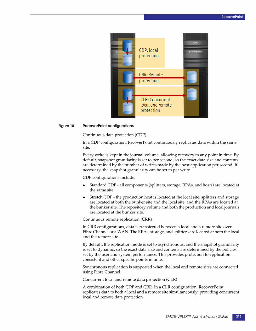
RecoverPoint
Figure 18 RecoverPoint configurations
Continuous data protection (CDP)
In a CDP configuration, RecoverPoint continuously replicates data within the samesite.
Every write is kept in the journal volume, allowing recovery to any point in time. Bydefault, snapshot granularity is set to per second, so the exact data size and contentsare determined by the number of writes made by the host application per second. Ifnecessary, the snapshot granularity can be set to per write.
CDP configurations include:
◆ Standard CDP - all components (splitters, storage, RPAs, and hosts) are located atthe same site.
◆ Stretch CDP - the production host is located at the local site, splitters and storageare located at both the bunker site and the local site, and the RPAs are located atthe bunker site. The repository volume and both the production and local journalsare located at the bunker site.
Continuous remote replication (CRR)
In CRR configurations, data is transferred between a local and a remote site overFibre Channel or a WAN. The RPAs, storage, and splitters are located at both the localand the remote site.
By default, the replication mode is set to asynchronous, and the snapshot granularityis set to dynamic, so the exact data size and contents are determined by the policiesset by the user and system performance. This provides protection to applicationconsistent and other specific points in time.
Synchronous replication is supported when the local and remote sites are connectedusing Fibre Channel.
Concurrent local and remote data protection (CLR)
A combination of both CDP and CRR. In a CLR configuration, RecoverPointreplicates data to both a local and a remote site simultaneously, providing concurrentlocal and remote data protection.
EMC® VPLEX™ Administration Guide 213
RecoverPoint
The CDP copy is normally used for operational recovery, while the CRR copy isnormally used for disaster recovery.
RecoverPoint/VPLEX configurationsRecoverPoint can be configured on VPLEX Local or Metro systems as follows:
◆ “VPLEX Local and RecoverPoint CDP”
◆ “VPLEX Local and RecoverPoint CRR/CLR”
◆ “VPLEX Metro and RecoverPoint CDP at one site”
◆ “VPLEX Metro and RecoverPoint CRR/CLR”
In VPLEX Local systems, RecoverPoint can replicate local volumes.
In VPLEX Metro systems, RecoverPoint can replicate local volumes and distributedRAID 1 volumes.
IMPORTANT!In VPLEX Metro systems, RecoverPoint can replicate only one VPLEX cluster.Replication at both VPLEX clusters is not supported.
Virtual volumes can be replicated locally (CDP), remotely (CRR), or both (CLR).
Distances between production sources and replication volumes vary based on therecovery objectives, inter-site bandwidth, latency, and other limitations outlined inthe EMC Simple Support Matrix (ESSM) for RecoverPoint.
VPLEX Local and RecoverPoint CDPIn VPLEX Local/RecoverPoint CDP configurations, I/O is split to replica volumesthat are located at the same site.
RPAs are deployed with the VPLEX cluster.
This configuration supports unlimited points in time, (with granularity up to a singlewrite) for local VPLEX virtual volumes. The CDP replica volume can be a VPLEXvirtual volume or any other heterogeneous storage supported by RecoverPoint.
Application event aware based rollback is supported for Microsoft SQL, MicrosoftExchange and Oracle database applications.
EMC® VPLEX™ Administration Guide214
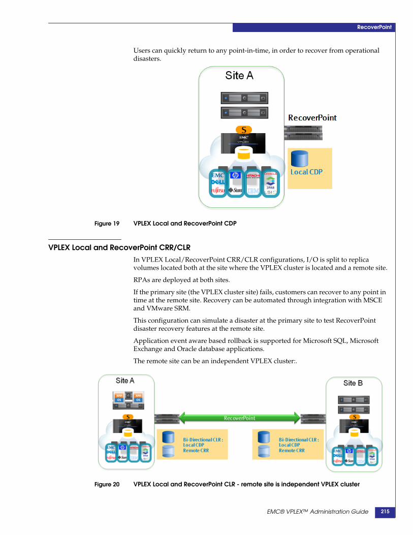
RecoverPoint
Users can quickly return to any point-in-time, in order to recover from operationaldisasters.
Figure 19 VPLEX Local and RecoverPoint CDP
VPLEX Local and RecoverPoint CRR/CLRIn VPLEX Local/RecoverPoint CRR/CLR configurations, I/O is split to replicavolumes located both at the site where the VPLEX cluster is located and a remote site.
RPAs are deployed at both sites.
If the primary site (the VPLEX cluster site) fails, customers can recover to any point intime at the remote site. Recovery can be automated through integration with MSCEand VMware SRM.
This configuration can simulate a disaster at the primary site to test RecoverPointdisaster recovery features at the remote site.
Application event aware based rollback is supported for Microsoft SQL, MicrosoftExchange and Oracle database applications.
The remote site can be an independent VPLEX cluster:.
Figure 20 VPLEX Local and RecoverPoint CLR - remote site is independent VPLEX cluster
EMC® VPLEX™ Administration Guide 215
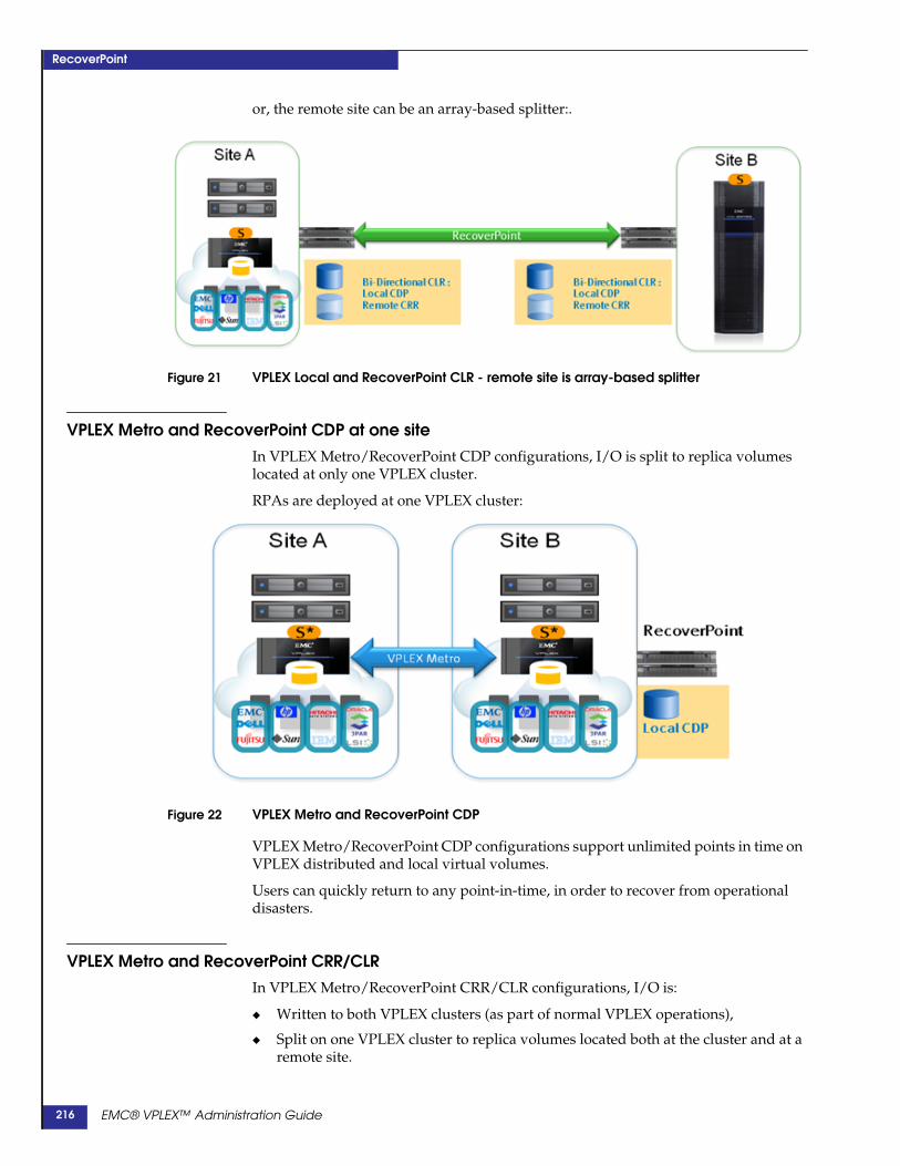
RecoverPoint
or, the remote site can be an array-based splitter:.
Figure 21 VPLEX Local and RecoverPoint CLR - remote site is array-based splitter
VPLEX Metro and RecoverPoint CDP at one siteIn VPLEX Metro/RecoverPoint CDP configurations, I/O is split to replica volumeslocated at only one VPLEX cluster.
RPAs are deployed at one VPLEX cluster:
Figure 22 VPLEX Metro and RecoverPoint CDP
VPLEX Metro/RecoverPoint CDP configurations support unlimited points in time onVPLEX distributed and local virtual volumes.
Users can quickly return to any point-in-time, in order to recover from operationaldisasters.
VPLEX Metro and RecoverPoint CRR/CLRIn VPLEX Metro/RecoverPoint CRR/CLR configurations, I/O is:
◆ Written to both VPLEX clusters (as part of normal VPLEX operations),
◆ Split on one VPLEX cluster to replica volumes located both at the cluster and at aremote site.
EMC® VPLEX™ Administration Guide216
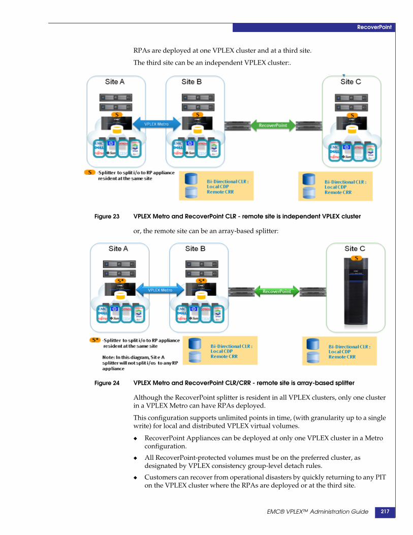
RecoverPoint
RPAs are deployed at one VPLEX cluster and at a third site.
The third site can be an independent VPLEX cluster:.
Figure 23 VPLEX Metro and RecoverPoint CLR - remote site is independent VPLEX cluster
or, the remote site can be an array-based splitter:
Figure 24 VPLEX Metro and RecoverPoint CLR/CRR - remote site is array-based splitter
Although the RecoverPoint splitter is resident in all VPLEX clusters, only one clusterin a VPLEX Metro can have RPAs deployed.
This configuration supports unlimited points in time, (with granularity up to a singlewrite) for local and distributed VPLEX virtual volumes.
◆ RecoverPoint Appliances can be deployed at only one VPLEX cluster in a Metroconfiguration.
◆ All RecoverPoint-protected volumes must be on the preferred cluster, asdesignated by VPLEX consistency group-level detach rules.
◆ Customers can recover from operational disasters by quickly returning to any PITon the VPLEX cluster where the RPAs are deployed or at the third site.
EMC® VPLEX™ Administration Guide 217
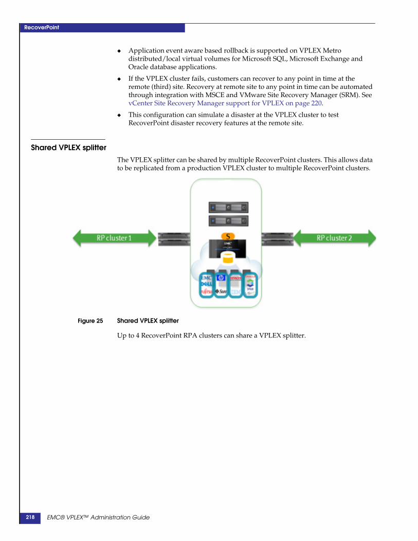
RecoverPoint
◆ Application event aware based rollback is supported on VPLEX Metrodistributed/local virtual volumes for Microsoft SQL, Microsoft Exchange andOracle database applications.
◆ If the VPLEX cluster fails, customers can recover to any point in time at theremote (third) site. Recovery at remote site to any point in time can be automatedthrough integration with MSCE and VMware Site Recovery Manager (SRM). SeevCenter Site Recovery Manager support for VPLEX on page 220.
◆ This configuration can simulate a disaster at the VPLEX cluster to testRecoverPoint disaster recovery features at the remote site.
Shared VPLEX splitterThe VPLEX splitter can be shared by multiple RecoverPoint clusters. This allows datato be replicated from a production VPLEX cluster to multiple RecoverPoint clusters.
Figure 25 Shared VPLEX splitter
Up to 4 RecoverPoint RPA clusters can share a VPLEX splitter.
EMC® VPLEX™ Administration Guide218
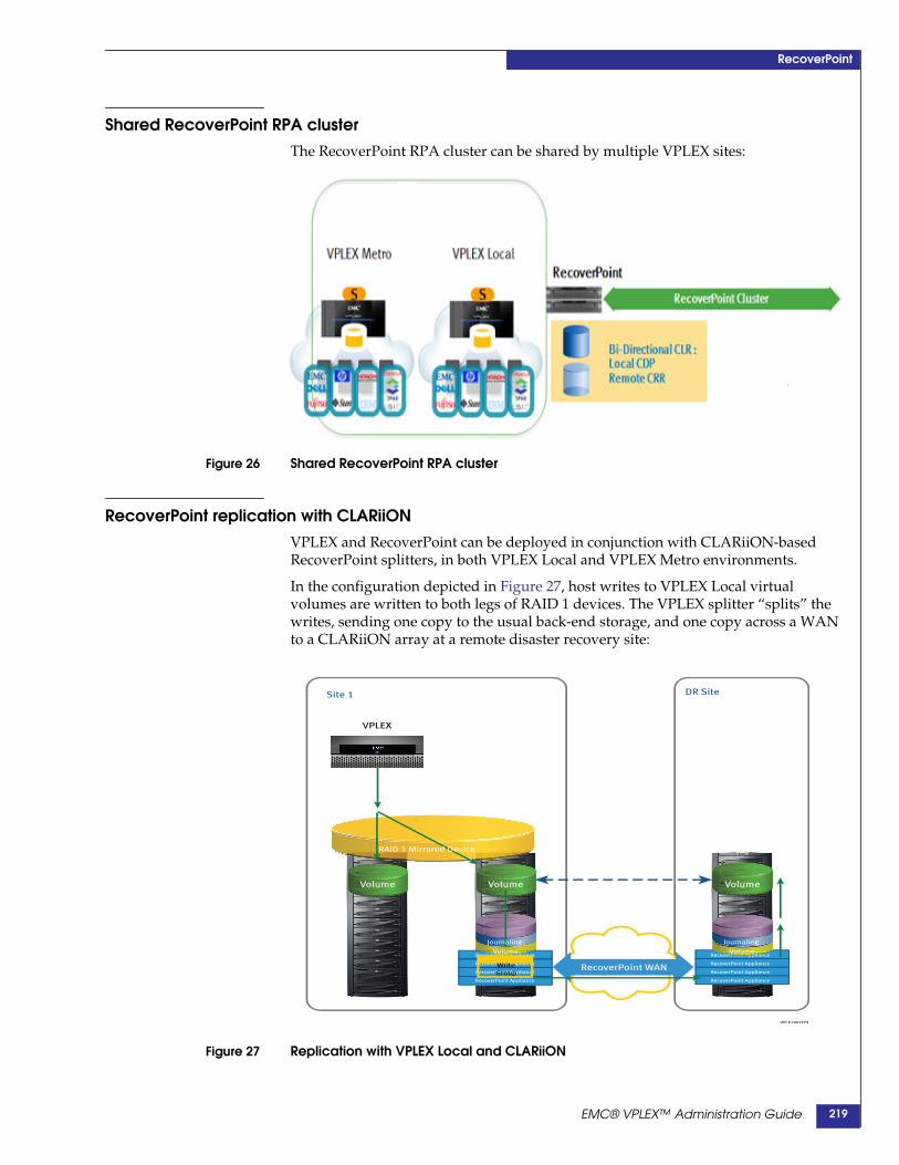
RecoverPoint
Shared RecoverPoint RPA clusterThe RecoverPoint RPA cluster can be shared by multiple VPLEX sites:
Figure 26 Shared RecoverPoint RPA cluster
RecoverPoint replication with CLARiiONVPLEX and RecoverPoint can be deployed in conjunction with CLARiiON-basedRecoverPoint splitters, in both VPLEX Local and VPLEX Metro environments.
In the configuration depicted in Figure 27, host writes to VPLEX Local virtualvolumes are written to both legs of RAID 1 devices. The VPLEX splitter “splits” thewrites, sending one copy to the usual back-end storage, and one copy across a WANto a CLARiiON array at a remote disaster recovery site:
Figure 27 Replication with VPLEX Local and CLARiiON
Site 1
VPLEX
RecoverPoint Appliance
RecoverPoint Appliance
RecoverPoint Appliance
RecoverPoint Appliance
coverPoint AAApplianncovveeerPoint AApplianliaRecoverPoint Appliance
RecoverPoint Appliance
RecoverPoint Appliance
RecoverPoint Appliance
overPoint AAppliaerPoint AApp li
DR Site
VPLX-000379
RecoverPoint WAN
RAID 1 Mirrored Device
Volume
Journaling
Volume
VolumeVolume
Journaling
Volume
WriteGroup
EMC® VPLEX™ Administration Guide 219

RecoverPoint
DR SiteSite 1
VPLEX
Site 2
VPLEX
RecoverPoint Appliance
RecoverPoint Appliance
RecoverPoint Appliance
RecoverPoint Appliance
RecoverPoint Appliance
RecoverPoint Appliance
RecoverPoint Appliance
RecoverPoint Appliance
overPoint AAppliaaanovveerPointt Appppllian verPoint ApppliaaveeerrrPoint Appppliian
VPLX-000378
RecoverPoint WAN
WAN - COM
Distributed Device
Volume
CLARiiON CLARiiON
Journaling
Volume
Journaling
Volume
Volume Volume
WriteGroup
In the configuration depicted in Figure 28, host writes to VPLEX Metro distributedvirtual volumes are similarly split, sending one copy to each of the VPLEX clusters,and a third copy across a WAN to a CLARiiON array at a remote disaster recoverysite:
Figure 28 Replication with VPLEX Metro and CLARiiON
vCenter Site Recovery Manager support for VPLEXWith RecoverPoint replication, you can add Site Recovery Manager support toVPLEX.
Figure 29 Support for Site Recovery Manager
When an outage occurs in VPLEX Local or VPLEX Metro configurations, the virtualmachine(s) can be restarted at the DR Site with automatic synchronization to theVPLEX configuration when the outage is over.
EMC® VPLEX™ Administration Guide220

RecoverPoint
RecoverPoint CLI contextRecoverPoint does not appear in the VPLEX CLI until the client has been configured.
Complete instructions to install RecoverPoint are available in the VPLEX ProcedureGenerator.
Descriptions of the CLI commands to add RecoverPoint are available in the VPLEXCLI Guide.
Use the rp rpa-cluster-add command to add a RecoverPoint RPA cluster:
VPlexcli:/> rp rpa-cluster add -o 10.6.210.79 -u admin -c cluster-1Enter rpa-cluster administrative password: Admin-passwordEnter rpa-cluster administrative password again for verification:
Admin-password
Once the RecoverPoint cluster is added, a CLI context called “recoverpoint” appearsin the CLI context tree:
VPlexcli:/> ll /recoverpoint/
/recoverpoint:Name Description------------ -----------------------------------------------------------------rpa-clusters Contains all the 'clusters' of RecoverPoint Appliances registered
in the system.
VPlexcli:/> ll /recoverpoint/rpa-clusters
/recoverpoint/rpa-clusters:RPA Host VPLEX Cluster RPA Site RPA ID RPA Version----------- ------------- -------- ------ -----------10.6.210.75 cluster-1 Site1 RPA 1 3.5(l.26)
VPlexcli:/> ll /recoverpoint/rpa-clusters/10.6.210.75
/recoverpoint/rpa-clusters/10.6.210.75:
Attributes:Name Value---------------------- -----------admin-username adminconfig-changes-allowed truerp-health-indications []rp-health-status okrp-software-serial-id -rpa-host 10.6.210.75rpa-id RPA 1rpa-site Site1rpa-version 3.5(l.26)vplex-cluster cluster-1
Contexts:Name Description------- -----------volumes -
VPlexcli:/> ll /recoverpoint/rpa-clusters/10.6.210.75/volumes
/recoverpoint/rpa-clusters/10.6.210.75/volumes:Name RPA RP Type RP Role RP VPLEX Capacity---------------------- Site ----------- ---------- Group Group ------------------------------ ----- ----------- ---------- ----- ---------- --------
EMC® VPLEX™ Administration Guide 221
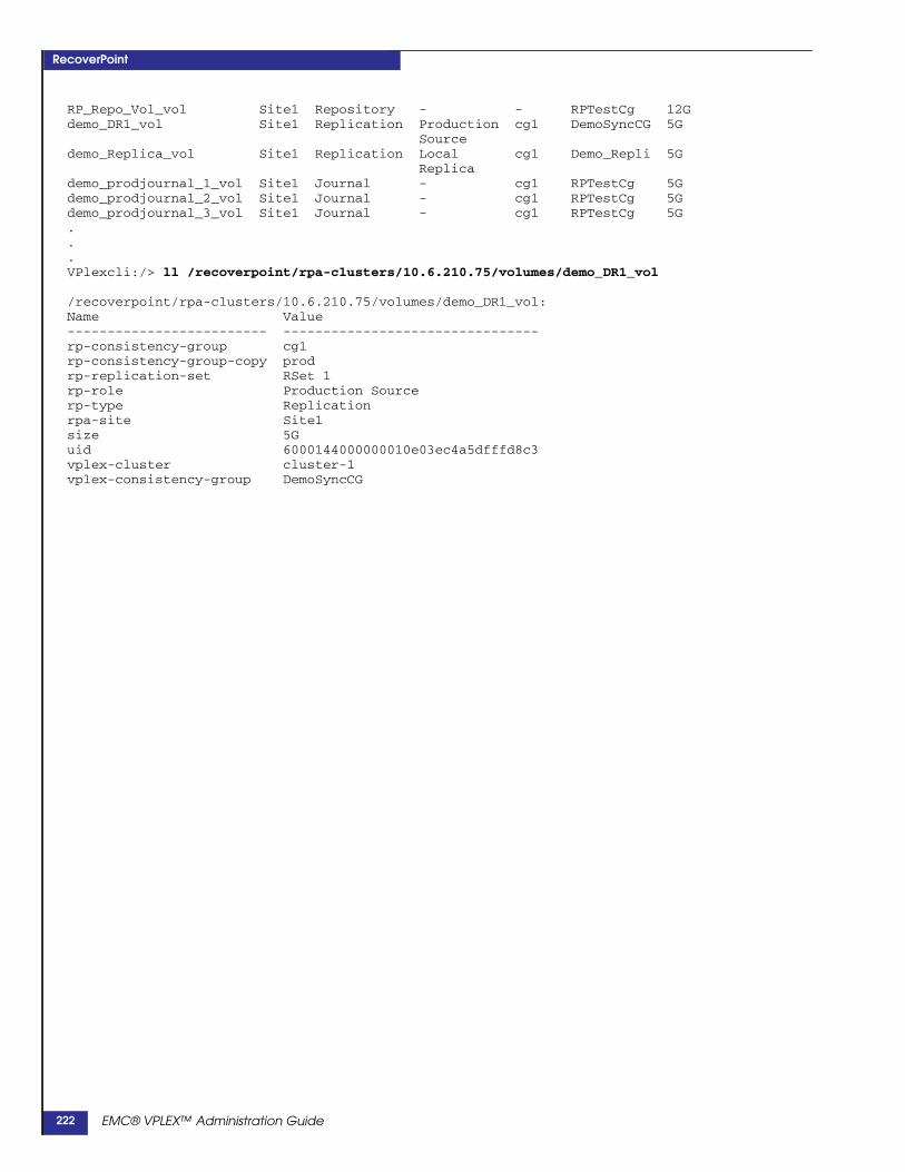
RecoverPoint
RP_Repo_Vol_vol Site1 Repository - - RPTestCg 12Gdemo_DR1_vol Site1 Replication Production cg1 DemoSyncCG 5G
Sourcedemo_Replica_vol Site1 Replication Local cg1 Demo_Repli 5G
Replicademo_prodjournal_1_vol Site1 Journal - cg1 RPTestCg 5Gdemo_prodjournal_2_vol Site1 Journal - cg1 RPTestCg 5Gdemo_prodjournal_3_vol Site1 Journal - cg1 RPTestCg 5G...VPlexcli:/> ll /recoverpoint/rpa-clusters/10.6.210.75/volumes/demo_DR1_vol
/recoverpoint/rpa-clusters/10.6.210.75/volumes/demo_DR1_vol:Name Value------------------------- --------------------------------rp-consistency-group cg1rp-consistency-group-copy prodrp-replication-set RSet 1rp-role Production Sourcerp-type Replicationrpa-site Site1size 5Guid 6000144000000010e03ec4a5dfffd8c3vplex-cluster cluster-1vplex-consistency-group DemoSyncCG
EMC® VPLEX™ Administration Guide222

RecoverPoint
Configuration/operation guidelines for VPLEX Metro and RP◆ “General restrictions/guidelines”
◆ “RecoverPoint repository volume”
◆ “VPLEX volumes”
◆ “VPLEX consistency groups”
◆ “VPLEX NDU”
◆ “Storage failures”
◆ “Logged image access”
◆ “Zoning”
• “About zoning: RPAs to VPLEX FE ports”
• “About zoning: RPAs to VPLEX BE ports”
• “About zoning: Distributed RecoverPoint consistency groups”
• “About zoning: Storage-to-VPLEX”
General restrictions/guidelinesIn VPLEX Metro configurations, RecoverPoint Appliances (RPAs) can be configuredat only one VPLEX cluster. Data from the cluster where the RPAs are configured isreplicated to the peer VPLEX cluster (by VPLEX), and to a third site (byRecoverPoint).
Virtual image access (see Image access on page 212) is not supported.
Device migrations between two VPLEX clusters are not supported if one leg of thedevice is replicated by RecoverPoint.
If a VPLEX director and a RecoverPoint Appliance are restarted at the same time, afull sweep may occur.
An RPA cluster supports up to 5,000 volumes exported to it from all storage arraysthat it can see, and up to 280,000 ITL paths.
RecoverPoint repository volumeOne RecoverPoint repository volume is required for each RPA cluster attached toVPLEX. The repository volume serves all RPAs of the particular cluster and splittersassociated with that cluster.
The repository volume should be configured on a VPLEX virtual volume with thefollowing attributes:
◆ 5.72 GB. Capacity beyond 5.72 GB is not used.
◆ RAID-1 device based on volumes in two different arrays
◆ Provisioned on non-thin storage
◆ Accessible to all RPAs at the site
◆ A local volume on the VPLEX cluster where the RPAs are configured
◆ Cannot be distributed
When VPLEX is installed into an existing RecoverPoint configuration, the repositoryvolume is already configured. There is no procedure to move a non-VPLEX
EMC® VPLEX™ Administration Guide 223

RecoverPoint
repository volume. When installing VPLEX into an existing RecoverPointconfiguration, continue using the non-VPLEX repository volume. When the storagearray that hosts the repository volume is refreshed, move the repository volume toVPLEX-hosted storage.
Once the repository volume is in VPLEX, it can be moved as needed.
Replica volumesRecoverPoint replica volumes must be exactly the same size as their associatedproduction volumes.
Performance of replica volumes should be the same or faster than their associatedproduction volumes.
◆ RecoverPoint CDP requires one replica volume on the production site for eachproduction volume.
◆ RecoverPoint CRR requires one replica volume on the remote site for eachproduction volume.
◆ RecoverPoint CLR requires one replica volume on production site AND one onthe remote site for each production volume.
Journal volumesPerformance is crucial for journal volumes.
Configure journal volumes on the fastest storage available.
RecoverPoint journal volumes must be local volumes on the VPLEX cluster where theRPAs are configured.
RecoverPoint journal volumes cannot be distributed volumes.
Refer to the EMC RecoverPoint Administrator’s Guide for information about sizingjournal volumes.
VPLEX volumes◆ Only VPLEX volumes that are members of a VPLEX consistency group with the
recoverpoint-enabled attribute set to “true” can be replicated by RecoverPoint.See recoverpoint-enabled on page 142.
◆ Virtual volumes that are replicated by RecoverPoint cannot be expanded.
Configure virtual volume size accordingly.
◆ Only local and distributed volumes can be replicated using RecoverPoint - notremote volumes.
◆ The following volumes may not be added to a VPLEX storage view created tosupport RecoverPoint:
• Remote volumes
• Volumes already in a different RecoverPoint storage view
• Volumes in VPLEX consistency groups whose members are in a differentRecoverPoint storage view
EMC® VPLEX™ Administration Guide224
RecoverPoint
Note: A RecoverPoint cluster may take up to 2 minutes to take note of changes to VPLEXconsistency groups. Wait for 2 minutes after making the following changes before creating orchanging a RecoverPoint consistency group:
- Adding or removing virtual volumes to/from a VPLEX consistency group- Enabling/disabling the recoverpoint-enabled property of a VPLEX consistency group- Changing the detach rule of a VPLEX consistency group
VPLEX consistency groups◆ Only VPLEX volumes that are members of VPLEX consistency groups with the
recoverpoint-enabled attribute set to “true” can be replicated by RecoverPoint.See recoverpoint-enabled on page 142.
◆ VPLEX supports a maximum of 128 recoverpoint-enabled consistency groups.
◆ Changes to VPLEX consistency groups may take up to 2 minutes to register inRecoverPoint. See Note: above.
◆ The cluster at which RPAs are configured must be the preferred cluster asdesignated by the VPLEX consistency group detach rules. See detach-rule onpage 140.
Administrators and VPLEX Witness can override the preferred clusterdesignation during inter-cluster link outages. See Failures in Metro Systems: WithVPLEX Witness on page 176.
For Production source volumes, this allows normal HA behavior. Writes to thepreferred cluster are logged for the duration of the link outage. When the link isrestored, a log rebuild copies only the logged changes to the splitter.
No snapshots are kept during the rebuild.
◆ All Production source volumes for a given RecoverPoint consistency groupshould be in one VPLEX consistency group. All the Replica volumes for a givenRecoverPoint consistency group should be in another VPLEX consistency group(not the same VPLEX consistency group as the Production source volumes).
If a RecoverPoint consistency group with a Production source volume and aReplica volume fails over, the Replica becomes the Production source. Having thereplica in a separate VPLEX consistency group assures that the hosts that thereplica now services (as the Production source volume) is write-order ensuredfrom a VPLEX standpoint.
◆ Replica volumes and Production source volumes may be on non-VPLEX storage,or on a separate VPLEX system.
◆ If a virtual volume is in a RP consistency group with the same role as other virtualvolumes in the VPLEX consistency group, it should be added to the VPLEXconsistency group.
VPLEX NDU
IMPORTANT!Confirm that the new version of VPLEX GeoSynchrony is compatible with theversion of RecoverPoint. Refer to the EMC VPLEX Release Notes for theGeoSynchrony release.
EMC® VPLEX™ Administration Guide 225

RecoverPoint
When a VPLEX cluster is being upgraded, it puts any RecoverPoint system it can talkto into maintenance mode.
When the upgrade is complete, VPLEX takes the RecoverPoint system out ofmaintenance mode.
When 2 VPLEX systems are connected to the same RecoverPoint cluster, the VPLEXsystems cannot be upgraded at the same time. Upgrade on the second VPLEX willfail until upgrade on the first VPLEX completes.
CAUTION!Do not upgrade VPLEX systems connected to the same RecoverPoint replicationenvironment at the same time.
Storage failures◆ If a storage volume (at the VPLEX cluster where the RPAs are configured) fails,
the host is still writing to the volume, and those writes are not included in thesnapshots of the VPLEX consistency group, and won't arrive until the rebuildoccurs.
◆ The RP site on a replica volume always becomes a winner (regardless of ClusterWitness or site restart), even if this triggers a conflicting detach (winner at bothsides).
In the case of a conflicting detach, as long as there is an active splitter (i.e.replication is not disabled), its host cluster must be the "datawin" target if theadministrator chooses to resolve the conflict
◆ In the case of storage failure of the mirror leg of a replica volume at the RP site,there must be a rebuild to correct the data on the replica. This will put the replicavolume into tracking mode (overriding fail-all), and rebuild I/O is allowed toproceed.
Logged image accessDuring logged image access (see Image access on page 212), the user selects asnapshot (PIT). The RecoverPoint system reverts the replica volume to the selectedPIT using the following steps:
◆ Stores the current state of the replica storage in the replica journal
◆ Reads historical data from the replica journal
◆ Re-writes the replica storage to reflect that historical data
When logged image access is disabled, this process is reversed.
When logged image access is first enabled, the RecoverPoint GUI displays "EnablingLogged Access". Once logged image access is enabled, the display changes to"Logged access (n% full)".
Click the Journal tab => target copy to display how much data remains to be writtenand remaining time to complete the writes.
Time to complete depends on the amount of data and on the performance of thejournal volume.
For example:
◆ To write 963GB of data;
EMC® VPLEX™ Administration Guide226

RecoverPoint
◆ At a rate of 91MB/sec
Expect the time to complete as ~3.5 hours.
ZoningRefer to RecoverPoint Deploying with VPLEX™ Technical Notes for detailedinformation. The following information is overview and guidance only.
Zoning is specific to site and topology. Best practice is to use the RPA Fibre Channelports as both initiators and targets to achieve maximum performance, redundancy,and optimal use of resource.
CAUTION!If, due to Initiator-Target LUN (ITL) limitations or other non-RecoverPointconsiderations, you need to zone RPA Fibre Channel ports in either the initiatorzone or the target zone, but not both, there are minor differences in performanceand availability. Initiator-target separation is not supported when:- Multiple splitter types are configured at the same RPA site- Using remote replication over FibreChannel- Using distributed RecoverPoint consistency groups
CAUTION!When using Fibre Channel ports that can be both initiators and targets, bestpractice is to add all initiator and target ports to the same zone.
About zoning: RPAs to VPLEX FE portsRecoverPoint requires read and write access to VPLEX virtual volumes.
All RecoverPoint Fibre Channel ports must be zoned to at least two front-end portson each VPLEX director of the VPLEX where splitting occurs.
All RecoverPoint appliances should be zoned to the same VPLEX front-end ports.
The following zoning rules apply:
◆ Each RPA must have at least two paths to the VPLEX cluster.
◆ For non-disruptive upgrades of RecoverPoint, each RecoverPoint appliance musthave at least one path to an A director and one path to a B director.
◆ Each RecoverPoint appliance should have at least two physical connections to thefront-end fabric switch.
◆ Each RPA should be zoned to provide paths to every virtual volume via at leasttwo directors.
EMC® VPLEX™ Administration Guide 227

RecoverPoint
Figure 30 Figure 1RPA to VPLEX Front End zoning
About zoning: RPAs to VPLEX BE portsThe RecoverPoint VPLEX splitter splits all incoming I/Os from both the front-endports and from the remote VPLEX cluster (in the Metro configuration). The VPLEXsplitter sends a copy of each write to the RPAs over the back-end ports.
Thus, every RecoverPoint HBA must be zoned to at least two VPLEX back-end portson each director of the VPLEX cluster where the RPA cluster is installed.
All RPAs should be zoned to the same VPLEX back-end ports. The RPAs are seen byVPLEX as storage targets (receiving writes); therefore, the appliances must be zonedaccording to the rules of zoning storage arrays:
◆ Each director in the VPLEX cluster must have redundant I/O paths to every RPA.
◆ Each director must have redundant physical connections to the back-end fabricswitches.
Note: Each director supports a maximum of four paths to any one RPA.
Figure 31 RPA to VPLEX Back End zoning
EMC® VPLEX™ Administration Guide228

RecoverPoint
About zoning: Distributed RecoverPoint consistency groupsDistributed RecoverPoint consistency groups require that all RecoverPoint FibreChannel ports in the fabric can communicate with each other.
To do so, they must all be in one zone.
Note: RecoverPoint-to-VPLEX back-end zoning usually satisfies this requirement.
About zoning: Storage-to-VPLEXFor VPLEX to access physical storage, arrays must be zoned to the VPLEX back-endas follows:
◆ Each director must have redundant I/O paths to every back-end storage array.
Best practice is that each director has redundant physical connections to theback-end storage fabrics.
◆ Each storage array must have redundant controllers.
Best practice is that at least two ports of each controller are connected to theback-end fabric.
Each director supports a maximum of 8 paths per volume.
EMC® VPLEX™ Administration Guide 229

RecoverPoint
Management toolsRecoverPoint can be managed using either a Command Line Interface (CLI) orGraphical User Interface (GUI).
RecoverPoint CLI Use the RecoverPoint CLI to manage and monitor activities interactively, or throughscripts.
There are two main modes of work in a CLI session:
CLI mode - Get help and interact with the system using CLI commands. CLI modeincludes:
◆ help mode - retrieve information regarding each CLI command, its parametersand usage.
◆ interactive mode - guide the user when running single commands, allowingthem to view each command parameter and its possible values while running thecommand.
◆ expert mode - input multiple parameters and their values for a single command.
Script mode - Interact with the system using scripts containing CLI commands.
To open a session with a RecoverPoint cluster or RPA and communicate using theCLI, create an SSH connection to either the site management IP (preferred, for aRecoverPoint cluster) or IP address of a specific RPA configured during aRecoverPoint installation.
The tools to work with the RecoverPoint CLI vary depending on which mode is usedto access the CLI.
◆ For CLI mode, download, install the free SSH connection utility PuTTY for Linuxor Unix.
◆ For Script mode, use the SSH utility that comes with the operating system, to runscripts and commands.
For more information about the command-line interface, see the EMC RecoverPointCommand Line Interface Reference Guide.
RecoverPoint GUI The RecoverPoint Graphical User Interface (GUI) is a java-based Web application.The GUI enables the user to monitor and manage a single RecoverPoint cluster.
To open a session with a RecoverPoint cluster or RPA:
◆ Open a browser window
◆ Type the site management IP (to connect to a RecoverPoint cluster) or IP addressof a specific RPA configured during a RecoverPoint installation, into the addressbar.
◆ Supply your RecoverPoint login credentials.
EMC® VPLEX™ Administration Guide230

12
This chapter describes RPO/RTO and the procedures to create and operateperformance monitors.
◆ About performance ......................................................................... 232◆ About performance monitoring ................................................... 234◆ Performance monitoring using the VPLEX GUI ......................... 235◆ Performance monitoring using the VPLEX CLI .......................... 236◆ Monitor performance using the CLI............................................ 237◆ Procedure overview: create a monitor using the CLI ................. 237◆ Create a monitor ............................................................................... 238◆ Force an immediate poll.................................................................. 245◆ Pre-configured performance monitors........................................ 246◆ Monitoring consistency groups using the CLI............................. 248◆ Monitoring with SNMP................................................................... 248◆ Statistics ............................................................................................ 251◆ Display available statistics .............................................................. 251◆ Statistics tables .................................................................................. 252
Performance andmonitoring
EMC® VPLEX™ Administration Guide 231

Performance and monitoring
About performanceThis chapter describes 2 topics related to performance on VPLEX systems:
◆ Configuration - Modifiable parameters to maximize performance and to manageRecovery Point Objective (RPO) and Recovery Time Objective (RTO) for VPLEXGeo systems.
◆ Monitoring - Tools and techniques to monitor VPLEX’s performance, and toidentify and diagnose problems.
RPO and RTORecovery Point Objective (RPO): RPO is the time interval between the point offailure of a storage system and the expected point in the past to which the storagesystem is capable of recovering customer data.
RPO is a maximum amount of data loss that can be tolerated by the application aftera failure. The value of the RPO is highly dependent upon the recovery techniqueused. For example, RPO for backups is typically days; for asynchronous replicationminutes; and for mirroring or synchronous replication seconds or instantaneous.
Recovery Time Objective (RTO): RTO is the time duration within which a storagesolution is expected to recover from failure and begin servicing application requests.
RTO is the longest tolerable application outage due to a failure of a storage system.RTO is a function of the storage technology. It may measure in hours for backupsystems, minutes for a remote replication, and seconds (or less) for a mirroring.
Calculating RPO in VPLEX Geo systemsVPLEX Geo systems, distributed volumes must be members of consistency groupswith asynchronous cache-mode.
Two additional parameters specific to asynchronous consistency groups impact theRPO:
◆ “default closeout-time” on page 144
◆ “maximum-queue-depth” on page 144
The default closeout-time and maximum-queue-depth properties work together toconfigure the maximum possible data loss in the event of an inter-cluster link outage.
In general:
RPO = roll_back_data (MB) / drain_rate (MB/s)
The maximum value for roll_back_data is computed as:
(max_queue_depth - 2) * delta_size * N
◆ 2 is subtracted from the maximum_queue_depth to exclude the WRITING andCOMMIT deltas which are never discarded (rolled back) during failure recovery.It is the unprotected deltas in states OPEN, CLOSED, or EXCHANGED that maybe lost.
◆ N is the number of directors at a cluster exporting volumes in AsynchronousConsistency Groups.
EMC® VPLEX™ Administration Guide232

Performance and monitoring
◆ The maximum drain rate is the rate at which cache pages can be exchanged andwritten to back-end storage, the rate at which deltas can be protected. Themaximum drain rate is a function of the inter-cluster WAN speed and backendstorage-array performance.
Note: Table 10 assumes the same number of engines configured in each cluster.
To calculate RPO, apply the drain rate. For example:
Assuming a drain rate of 100 MB/s:
◆ 1 engine clusters = 4 GB maximum loss = ~42 seconds
◆ 2 engine clusters = 8 GB maximum loss = ~ 1 minute 22 seconds
◆ 4 engine clusters = 16 GB maximum loss = ~2 minutes 44 seconds
Table 11 shows the impact of increasing the maximum queue depth from the defaultvalue of 6 to the maximum value of 64 for systems with the maximum number ofasynchronous consistency groups (16) configured:
Table 10 Parameters impacting RPO in Geo configurations
Parameter Default Maximum Configurable?
Number of clusters 2 2 -
Number of asynchronousconsistency groups
0 - 16 16 -
Maximum queue depth 6 64 Yes
Delta size 16 MB 16 MB No
Closeout time 30 seconds 0 (no closeout time) Yes
Table 11 Maximum roll back loss for Geo with 16 asynchronous consistency groups
Engines/cluster
Total #directors
Max queuedepth Max roll back loss
1 4 6 (default) 4.0 GB
1 4 64 62.0 GB
2 8 6 8.0 GB
2 8 64 124.0 GB
4 16 6 16.0 GB
4 16 64 248.0 GB
EMC® VPLEX™ Administration Guide 233

Performance and monitoring
About performance monitoringPerformance monitors collect and displays statistics to determine how a port orvolume is being used, how much I/O is being processed, CPU usage, and so on.
Performance monitoring is supported in both the VPLEX CLI and GUI, and falls intothree general types:
◆ Current load monitoring allows administrators to watch CPU load duringupgrades, I/O load across the inter-cluster WAN link, and front-end vs. back-endload during data mining or back up.
Current load monitoring is supported in the GUI.
◆ Long term load monitoring collects data for capacity planning and loadbalancing.
Long term load monitoring is supported by monitors created in the CLI and/orperpetual monitors.
◆ Troubleshooting monitoring helps identify bottlenecks and resource hogs.
Troubleshooting monitors are supported by monitors created in the CLI and/orperpetual monitors.
Note: In the GUI, performance statistics are displayed per cluster. To view statistics for bothclusters in a Metro or Geo, connect to both clusters.
Custom monitors You can use the CLI to create custom monitors to collect and display selected statisticsfor selected targets.
See “Monitor performance using the CLI” on page 237.
Preconfigured monitorsUse the report create-monitors command to create three pre-configured monitors foreach director.
See “Pre-configured performance monitors” on page 246.
Perpetual monitorsStarting in Release 5.0, GeoSynchrony includes perpetual monitors that gather astandard set of performance statistics every 30 seconds.
Note: Perpetual monitors do not collect per volume statistics.
Perpetual monitor files are collected as part of collect-diagnostics. Collect-diagnosticsis per cluster, so in Metro or Geo configurations, you must run the command fromboth VPLEX management servers.
Output of perpetual monitors is captured in the file smsDump_<date>.zip inside thebase collect-diagnostics zip file.
Within smsDump_<date>.zip file, monitor files are in clilogs/.
You can also copy the perpetual files from the management server. They are locatedin /var/log/VPlex/cli/. There is one perpetual monitor file per director, identifiableby the keyword “PERPETUAL”
For example: director-1-1-A_PERPETUAL_vplex_sys_perf_mon.log
EMC® VPLEX™ Administration Guide234

Performance and monitoring
Performance monitoring using the VPLEX GUIThe performance monitoring dashboard provides a customized view into theperformance of your VPLEX system. You decide which aspects of the system'sperformance to view and compare.
Figure 32 Performance monitoring dashboard
Performance information for the current 5-minute window is displayed as a set ofcharts, including:
◆ WAN Link Performance chart - Shows the WAN link performance for the clusterto which you are connected. Use this chart to monitor link performance to helpdetermine the bandwidth requirements for your specific environment, gatherstatistical data over time, monitor network traffic during peak periods, or to plandata mobility jobs to avoid peak usage times.
◆ WAN Link Usage chart - Shows the WAN link usage for the cluster to which youare connected. Use this chart to monitor link usage to help determine thebandwidth requirements for your specific environment, gather statistical dataover time, monitor network traffic during peak periods, or to plan data mobilityjobs to avoid peak usage times. The chart allows you to separately monitor theamount of bandwidth used for normal system operations, writes to distributedvolumes, and mobility jobs.
◆ Back-end Latency chart - Provides details of the back-end latency statistics foryour VPLEX system in graphical form over time. The chart allows you to viewcurrent or historical performance data that you can use to monitor peaks inworkload, detect performance issues, or view what was happening in the systemwhen a specific problem occurred.
◆ Front-end Latency chart - Provides details of the front-end latency statistics foryour VPLEX system in graphical form over time. The chart allows you to viewcurrent or historical performance data that you can use to monitor peaks inworkload, detect performance issues, or view what was happening in the systemwhen a specific problem occurred.
EMC® VPLEX™ Administration Guide 235

Performance and monitoring
◆ Rebuild Status chart - Displays the status of any rebuilds that are running onyour VPLEX system.
◆ CPU Utilization chart - Provides a time-based view of the utilization load on thedirector CPUs of your VPLEX system. By default, the chart shows an averagedview of the utilization loads of all of the CPUs on all the directors in your VPLEXsystem.
◆ Front-end Aborts chart - Displays the number of aborts per second over time fordirectors on your VPLEX system. By default, the chart shows an averagedfront-end aborts for the VPLEX system.
◆ Subpage Writes chart - Displays the percentage of subpage writes over time fordirectors on your VPLEX system. By default, the chart shows an averagedsubpage writes chart for the VPLEX system.
◆ Front-End Throughput chart - Displays the front-end I/Os per second over timefor directors on your VPLEX system. By default, the chart shows the totalfront-end throughput for the VPLEX system.
◆ Front-End Bandwidth chart - Displays the quantity of front-end reads and writesper second over time for directors on your VPLEX system. By default, the chartshows the total front-end bandwidth for the VPLEX system.
Performance monitoring using the VPLEX CLIUse the CLI to create custom monitors to help diagnose performance issues.
Two CLI objects collect and display performance statistics:
◆ monitors - Gather the specified statistic from the specified target at the specifiedinterval.
◆ monitor sinks - Direct the output to the desired destination. Monitor sinksinclude the console, a file, or a combination of the two.
Note: SNMP statistics do not require a monitor or monitor sink. Use the snmp-agent configurecommand to configure and start the SNMP agent. Refer to “Performance statistics retrievableby SNMP” on page 262.
EMC® VPLEX™ Administration Guide236
Performance and monitoring
Monitor performance using the CLIThis section describes the steps to create a custom monitor using the VPLEX CLI,including:
◆ “Procedure overview: create a monitor using the CLI”
◆ “Create a monitor”
◆ “Add/delete monitor sinks”
◆ “Delete a monitor”
◆ “Display monitors”
◆ “Force an immediate poll”
About file rotation and timestampsStarting in Release 5.1, the log files created by a monitor’s file sink are automaticallyrotated when they reach a size of 10 MB. The 10MB file is saved as filename.csv.nwhere n is a number 1 - 10, and output is saved in a new file named filename.csv.n+1.
The .csv files are rotated up to 10 times.
In the following example, a monitor has exceeded 10MB of output. The initial 10MBare stored in filename.csv.1. Subsequent output is stored in filename.csv.
service@sms-cluster-1:/var/log/VPlex/cli> ll my-data.csv*-rw-r--r-- 1 service users 2910722 2012-03-06 21:23 my-data.csv-rw-r--r-- 1 service users 10566670 2012-03-06 21:10 my-data.csv.1
If the second file exceeds, 10MB:
◆ The previous filename.csv.1 is changed to filename.csv.2
◆ The filename.csv changes to filename.csv.1
◆ Subsequent output is stored in filename.csv
Up to 10 such rotations, and numbered .csv files are supported.
When the file sink is removed or the monitor is destroyed, output to the .csv filestops, and the current .csv file is is timestamped. For example:
service@sms-cluster-1:/var/log/VPlex/cli> ll my-data.csv*-rw-r--r-- 1 service users 10566670 2012-03-06 21:23 my-data.csv.1-rw-r--r-- 1 service users 5637498 2012-03-06 21:26my-data.csv_20120306092614973
Procedure overview: create a monitor using the CLITo create and operate a monitor using the CLI, use the following general steps:
1. Determine the type of statistic to collect from the target object.
Use the monitor stat-list category and/or the monitor stat-list * command todisplay the statistics to include in the monitor.
Refer to the tables in “Statistics” on page 251 for lists of statistics by category.
Note whether the statistic you want to collect requires a target to be specified.
EMC® VPLEX™ Administration Guide 237

Performance and monitoring
Note: Specify only one type of target per monitor. For example, you cannot create amonitor that includes both port and storage-volumes as targets.
2. Determine how often the monitor should collect statistics.
3. Use the monitor create command to create a monitor.
4. Use the monitor add-sink commands to add one or more sinks to the monitor.
Add a console sink to send performance data to the VPLEX management console.
Add a file sink to send performance data to a specified file.
5. Repeat Steps 3 and 4 for each director.
6. The monitor begins operation (polling and collecting performance data) when thesink is added to the monitor.
To disable automatic polling without deleting the monitor or its sink(s), do one ofthe following:
• Use the set command to change the monitor’s period attribute to 0.
• Use the set command to change the sink’s enabled attribute to false.
7. Use the monitor collect command to update/collect statistics immediatelywithout waiting for the monitor’s next automatic collection.
8. Monitor output.
Console sinks display monitor output on the console.
For file sinks, navigate to /var/log/VPlex/cli/ on the management server anduse the tail -f filename to display the output,
or:
Send output to a csv file, open the file in Microsoft Excel and create a chart.
WARNING
Do NOT edit the CSV file in Microsoft Excel, and then save the file. Excelremoves the seconds field, resulting in duplicate timestamps. Use Excel to look atthe CSV files, but don’t save any edits.
9. Use the monitor destroy command to remove the monitor.
Create a monitorUse the monitor create command to create a monitor and specify the statisticscollected by the monitor.
The syntax for the command is:
monitor create[-p|--period] collection-period[-n|--name] monitor-name[-d|--director] context-path,context-path[-s|--stats] stat,stat,stat,stat[-t|--targets] context-path,context-path
Required arguments--name - Name of the monitor.
--stats stat,stat,stat - One or more statistics to monitor, separated by commas.
EMC® VPLEX™ Administration Guide238
Performance and monitoring
Optional arguments-- period - Frequency at which this monitor collects statistics. Valid arguments are aninteger followed by:
ms - milliseconds (period is truncated to the nearest second)s - seconds (Default)min - minutesh - hours0 - Disables automatic polling
The default period is 30 seconds.
--director context path, context path... - Context path(s) to one or more directors todisplay statistics for. Separated by commas.
--targets context path, context path... - Context path(s) to one or more targets todisplay statistics for, separated by commas. Applicable only to statistics that require atarget.
Example: default period, no targetsCreate a simple monitor with the default period, and no targets:
VPlexcli:/monitoring> monitor create --name TestMonitor --director Director-2-1-B --statsdirector.fe-read,director.fe-writeSuccessfully created 1 monitor(s) out of 1.
Example: 10 seconds, directorsCreate a monitor to collect statistics from the director category on/engines/engine-1-1/directors/director-1-1-A every 10 seconds:
VPlexcli:/monitoring> monitor create --name DirStats --period 10s --director/engines/engine-1-1/directors/director-1-1-A --stats director.*
Example: all statistics for all volumesCreate a monitor to collect statistics on all storage volumes at cluster-1:
VPlexcli:/monitoring> monitor create --name SVStats-Cluster1 --director/engines/engine-1-1/directors/director-1-1-A --stats storage-volume.* --targets/clusters/cluster-1/storage-elements/storage-volumes/*
Example: fe statistics for a specified fe portCreate a monitor to collect all front-end statistics on front-end port FC01:
VPlexcli:/monitoring> monitor create --name FE-FC01-stats --director/engines/engine-1-1/directors/director-1-1-A --stats fe-prt.* --targets/engines/engine-1-1/directors/director-1-1-A/hardware/ports/A0-FC01
Example: udt port statistics for a specified directorCreate a performance monitor to collect UDT port statistics for ports on the specifieddirector:
VPlexcli:/monitoring> monitor create --name Director-1-1-A-UDT --director/engines/engine-1-1/directors/director-1-1-A --stats director.udt*
Example: port-level WAN statisticsCreate a performance monitor to collect port-level WAN-COM statistics:
EMC® VPLEX™ Administration Guide 239

Performance and monitoring
VPlexcli:/monitoring> monitor create --name WAN_A2-XG00 --director/engines/engine-1-1/directors/director-1-1-A --stats ip-com-port.* --targets/engines/engine-1-1/directors/director-1-1-A/hardware/ports/A2-XG00
Example: Send CAW statistics to the management server◆ Create a performance monitor to collect statistics for CompareAndWrite (CAW)
operations, miscompares, and latency for the specified virtual volume ondirector-1-1-B.
◆ Add a file sink to send output to the specified directory on the managementserver.
VPlexcli:/monitoring/directors/director-1-1-B/monitors> monitor create --name fe_lu_caw--director /engines/engine-1-1/directors/director-1-1-B --stats fe-lu.caw* --targets/clusters/cluster-1/virtual-volumes/VAAI_Vol1_Device_vol
VPlexcli:/monitoring/directors/director-1-1-B/monitors> cd director-1-1-B_fe_lu_caw/sinks
VPlexcli:/monitoring/directors/director-1-1-B/monitors/director-1-1-B_fe_lu_caw/sinks>monitor add-file-sink /var/log/VPlex/cli/director-1-1-B_fe_lu_caw
Add/delete monitor sinksEvery monitor must have at least one sink, and may have multiple sinks. There aretwo types of sink:
console - Sends output to VPLEX management server console.
file - Sends output to the specified file.
Add a console sinkUse the monitor add-console-sink command to add a console sink to an existingmonitor.
CAUTION!Console monitors display the specified statistics on the VPLEX ManagementConsole, interrupting any other input/output to/from the console.
The syntax for the command is:
add-console-sink[-o|--format] {csv|table}[-m|--monitor] monitor-name--force
The default format for console sinks is ‘table’.
To add a console sink with output formatted as table (the default output format):
VPlexcli:/> monitor add-console-sink --monitor Director-2-1-B_TestMonitor
Navigate to the monitor context and use the ll console command to display the sink:
VPlexcli:/cd monitoring/directors/Director-2-1-B/monitors/Director-2-1-B_TestMonitor/sinksVPlexcli:/monitoring/directors/Director-2-1-B/monitors/Director-2-1-B_TestMonitor/sinks> ll
Name Enabled Format Sink-To------- ------- ------ -------console true table console
VPlexcli:/monitoring/directors/Director-2-1-B/monitors/Director-2-1-B_TestMonitor/sinks> llconsole
EMC® VPLEX™ Administration Guide240
Performance and monitoring
/monitoring/directors/Director-2-1-B/monitors/Director-2-1-B_TestMonitor/sinks/console:Name Value------- -------enabled trueformat tablesink-to consoletype console
Add a file sink Use the monitor add-file-sink command to add a file sink to an existing monitor.
The syntax for the command is:
add-file-sink[-n|--name] sink-name[-o|--format] {csv|table}[-m|--monitor] monitor-name[-f|--file] file--force
The default format for file sinks is csv (comma-separated values).
The default name of the new sink is 'file”.
The default location for the sink output is /var/log/VPlex/cli.
To add a file sink to send output to the specified .csv file:
VPlexcli:/monitoring/directors/director-1-1-A/monitors> monitor add-file-sink --monitordirector-1-1-A_stats --file /var/log/VPlex/cli/director_1_1_A.csv
Navigate to the monitor sinks context and use the ll sink-name command to displaythe sink:
VPlexcli:/cd monitoring/directors/Director-1-1-A/monitors/director-1-1-A_stats/sinksVPlexcli:/monitoring/directors/Director-1-1-A/monitors/director-1-1-A_stats/sinks> ll file
/monitoring/directors/Director-1-1-A/monitors/director-1-1-A_stats/sinks/file:Name Value------- -------------------------------enabled trueformat csvsink-to /var/log/VPlex/cli/director_1_1_A.csvtype file
Delete a monitor sinkUse the monitor remove sink command to remove a sink from a monitor:
VPlexcli:/monitoring/directors/director-2-1-B/monitors/director-2-1-B_TestMonitor> monitorremove-sink console
Delete a monitorUse the monitor destroy monitor command to delete a specified monitor.
For example:
VPlexcli:/monitoring/directors/director-1-1-B/monitors> monitor destroydirector-1-1-B_TestMonitor
WARNING: The following items will be destroyed:
Context----------------------------------------------------------------------------/monitoring/directors/director-1-1-B/monitors/director-1-1-B_TestMonitor
EMC® VPLEX™ Administration Guide 241
Performance and monitoring
Do you wish to proceed? (Yes/No) y
Display monitorsUse the ls /monitoring/directors/*/monitors command to display the names of allmonitors configured on the system:
VPlexcli:/> ls /monitoring/directors/*/monitors
/monitoring/directors/director-1-1-A/monitors:DEFAULT_director-1-1-A_PERPETUAL_vplex_sys_perf_mon_v8director-1-1-A_Billy35_FE_A0-FC00_statsdirector-1-1-A_director-fe-21112011director-1-1-A_diskReportMonitor.../monitoring/directors/director-1-1-B/monitors:DEFAULT_director-1-1-B_PERPETUAL_vplex_sys_perf_mon_v8...
Use the ll /monitoring/directors/director/monitors command to display summarizedinformation about all the monitors for the specified context/object:
VPlexcli:/> ll /monitoring/directors/director-1-1-A/monitors
/monitoring/directors/director-1-1-A/monitors:Name Ownership Collecting Period Average Idle Bucket Bucket Bucket Bucket----------------------------- --------- Data ------ Period For Min Max Width Count------------------------------- --------- ---------- ------ ------- ---- ------ ------ ------ ------director-1-1-A_FE_A0-FC00 false false 5s - - - - - 64director-1-1-A_director-fe false false 5s - - - - - 64director-1-1-A_ipcom-21112011 false false 5s - - - - - 64director-1-1-A_portReportMon false false 5s - - - - - 64...
Use the ll /monitoring/directors/director/monitors/monitor-name command todisplay detailed information about all the specified monitor:
VPlexcli: ll /monitoring/directors/Director-2-1-B/monitors/Director-2-1-B_volumeReportMonitor
Attributes:Name Value--------------- --------------------------------------------------------------average-period -bucket-count 64bucket-max -bucket-min -bucket-width -collecting-data truefirmware-id 9idle-for 5.44daysownership trueperiod 0sstatistics [virtual-volume.ops, virtual-volume.read,
virtual-volume.write]targets DR1_C1-C2_1gb_dev10_vol, DR1_C1-C2_1gb_dev11_vol,
DR1_C1-C2_1gb_dev12_vol, DR1_C1-C2_1gb_dev13_vol,DR1_C1-C2_1gb_dev14_vol, DR1_C1-C2_1gb_dev15_vol,DR1_C1-C2_1gb_dev16_vol, DR1_C1-C2_1gb_dev17_vol,DR1_C1-C2_1gb_dev18_vol, DR1_C1-C2_1gb_dev19_vol, ... (1300total)
EMC® VPLEX™ Administration Guide242
Performance and monitoring
Contexts:Name Description----- ------------------------------------------------------------------------sinks Contains all of the sinks set up to collect data from this performance
monitor.Use the ll/monitoring/directors/director/monitors/monitor-name/sinkscommand to display the sinks associated with the specified monitor:
VPlexcli: ll/monitoring/directors/Director-2-1-B/monitors/Director-2-1-B_volumeReportMonitor/sinks
/monitoring/directors/bob70/monitors/bob70_volumeReportMonitor/sinks:Name Enabled Format Sink-To---- ------- ------ --------------------------------------------------------file true csv /var/log/VPlex/cli/reports/volumeReportMonitor_bob70.csv
Table 12 Monitor and sink field descriptions (1 of 2)
Field Description
average-period The actual average sampling period.
bucket-count The number of buckets used for gathering statistics.
bucket-max The upper bound for bucketed statistics being monitored.
bucket-min The lower bound for bucketed statistics being monitored.
bucket-width The width of the range of values that a given bucket represents. Use this to adjust the upper bound ofmonitoring.
collecting-data Whether or not this performance monitor is collecting data. A monitor collects data if it has at least oneenabled sink.
firmware-id The firmware ID of the monitor.
idle-for The elapsed time since this performance monitor was accessed in the firmware.
name A director-wide unique name for this performance monitor intended to be meaningful to the user.
ownership Whether or not this monitor was created in this instance of VPlex Management Console.
period Sampling period in seconds.
statistics List of performance statistics that are being monitored.
EMC® VPLEX™ Administration Guide 243

Performance and monitoring
Enable/disable/change pollingPolling (collection of the specified statistics) begins when the first sink is added to amonitor. Polling occurs automatically at the interval specified by the monitor’speriod attribute.
Use the set command to change the polling period.
Use the monitor collect command to run a collection immediately, before its definedpolling interval.
Use the set command to disable, or modify automatic polling for a monitor.
In the following example:
◆ The set command changes the period attribute to 0, disabling automatic polling
◆ The ll command displays the change:
VPlexcli:/monitoring/directors/director-2-1-B/monitors/director-2-1-B_TestMonitor> set period0
VPlexcli:/monitoring/directors/director-2-1-B/monitors/director-2-1-B_TestMonitor> ll
Attributes:Name Value--------------- --------------------------------------------------------------average-period -bucket-count 64bucket-max -bucket-min -bucket-width -collecting-data falsefirmware-id 4idle-for 5.78minownership trueperiod 0s...
To re-enable polling, use the set command to change the period attribute to anon-zero value.
targets List of targets that apply to the monitored performance statistics. A target can be a port,storage-volume, or virtual volume.
Note: Not all statistics require targets.
Monitor sink display fields
Name For file sinks, the name of the created sink context. Default is 'file'.
Enabled Whether the monitor sink is enabled or disabled.
Format The required output format. Can be 'csv' or 'table'.Default is 'csv' for file sinks and “table” for console sinks.
Sink-To For file sinks, the filename to sink data to.
Table 12 Monitor and sink field descriptions (2 of 2)
Field Description
EMC® VPLEX™ Administration Guide244

Performance and monitoring
Enable/disable sinksUse the set command to enable/disable a monitor sink.
To disable a monitor sink:
VPlexcli:/monitoring/directors/director-2-1-B/monitors/director-2-1-B_TestMonitor/sinks/console> set enabled false
VPlexcli:/monitoring/directors/director-2-1-B/monitors/director-2-1-B_TestMonitor/sinks/console> llName Value------- -------enabled falseformat tablesink-to consoletype console
To enable a monitor sink:
VPlexcli:/monitoring/directors/director-2-1-B/monitors/director-2-1-B_TestMonitor/sinks/console> set enabled true
VPlexcli:/monitoring/directors/director-2-1-B/monitors/director-2-1-B_TestMonitor/sinks/console> llName Value------- -------enabled trueformat tablesink-to consoletype console
Force an immediate pollUse the monitor collect monitor command to force an immediate poll and collectionof performance data without waiting for the automatic poll interval.
For example:
VPlexcli:/> monitor collect/monitoring/directors/director-2-1-B/monitors/director-2-1-B_TestMonitor
VPlexcli:/>Source: director-2-1-B_TestMonitorTime: 2010-07-01 10:05:55director.be-ops (counts/s):...
EMC® VPLEX™ Administration Guide 245

Performance and monitoring
Pre-configured performance monitorsThis section describes the following topics:
◆ “About pre-configured monitors”
◆ “Create pre-configured monitors”
◆ “Operate the pre-configured monitors”
About pre-configured monitorsPre-configured monitors are an easy way to create monitors to collect informationused to diagnose common problems.
The report create-monitors command creates three monitors for each director in thesystem. Monitors are named:
◆ Cluster_n_Dir_nn_diskReportMonitor
◆ Cluster_n_Dir_nn_portReportMonitor
◆ Cluster_n_Dir_nn_volumeReportMonitor
The period attribute for the new monitors is set to 0 (automatic polling is disabled).
The report poll-monitors command is used to force a poll.
Each monitor has one file sink. The file sinks are enabled.
By default, output files are located in:
/var/log/VPlex/cli/reports/
on the management server. Output filenames are in the following format:
<Monitor name>_Dir_nn.csv
◆ Pre-configured disk monitors collect the following statistics:
• storage-volume.per-storage-volume-read-latency
• storage-volume.per-storage-volume-write-latency
◆ Pre-configured port monitors collect the following statistics:
• be-prt.read
• be-prt.write
• fe-prt.ops
• fe-prt.read
• fe-prt.write
◆ Pre-configured volume monitors collect the following statistics:
• virtual-volume.ops
• virtual-volume.read
• virtual-volume.write
EMC® VPLEX™ Administration Guide246

Performance and monitoring
Create pre-configured monitorsIn the following example:
◆ The report create-monitors command creates a diskReportMonitor,portReportMonitor, and volumeReportMonitor for each director,
◆ The ll //monitoring/directors/*/monitors command displays the new monitors:
VPlexcli:/> report create-monitorsCreating monitor diskReportMonitor on Director Cluster_1_Dir1A monitoring 981 targets, file/var/log/VPlex/cli/reports/diskReportMonitor_Cluster_1_Dir1A.csv.Successfully created 1 monitor(s) out of 1.
time: 11 secCreating monitor volumeReportMonitor on Director Cluster_1_Dir1A monitoring 30 targets, file/var/log/VPlex/cli/reports/volumeReportMonitor_Cluster_1_Dir1A.csv.Successfully created 1 monitor(s) out of 1.
time: 0 secCreating monitor portReportMonitor on Director Cluster_1_Dir1A monitoring 16 targets, file/var/log/VPlex/cli/reports/portReportMonitor_Cluster_1_Dir1A.csv.Successfully created 1 monitor(s) out of 1.Creating monitor diskReportMonitor on DirectorCluster_1_Dir1A monitoring 981 targets, file/var/log/VPlex/cli/reports/diskReportMonitor_Cluster_1_Dir1A.csv.Successfully created 1 monitor(s) out of 1....VPlexcli:/> ll //monitoring/directors/*/monitors
/monitoring/directors/Cluster_1_Dir1A/monitors:Name Ownership Collecting Period Average Idle For Bucket Bucket Bucket Bucket----------------------------------- --------- Data ------ Period -------- Min Max Width Count----------------------------------- --------- ---------- ------ ------- -------- ------ -------Cluster_1_Dir1A_diskReportMonitor true true 0s - 7.1min 100 1600100 25000 64Cluster_1_Dir1A_portReportMonitor true true 0s - 6.88min - - - 64Cluster_1_Dir1A_volumeReportMonitor true true 0s - 6.9min - - - 64
/monitoring/directors/Cluster_1_Dir1B/monitors:Name Ownership Collecting Period Average Idle Bucket Bucket Bucket Bucket----------------------------------- --------- Data ------ Period For Min Max Width Count----------------------------------- --------- ---------- ------ ------- ------- ------ -------Cluster_1_Dir1B_diskReportMonitor true true 0s - 6.88min 100 1600100 25000 64Cluster_1_Dir1B_portReportMonitor true true 0s - 6.68min - - - 64Cluster_1_Dir1B_volumeReportMonitor true true 0s - 6.7min - - - 64...
An empty .csv file is created on the management server for each of the monitors:
service@ManagementServer:/var/log/VPlex/cli/reports> lltotal 36...-rw-r--r-- 1 service users 0 2010-08-19 13:55 diskReportMonitor_Cluster_1_Dir1A.csv-rw-r--r-- 1 service users 0 2010-08-19 13:55 diskReportMonitor_Cluster_1_Dir1B.csv-rw-r--r-- 1 service users 0 2010-08-19 13:56 diskReportMonitor_Cluster_2_Dir_1A.csv-rw-r--r-- 1 service users 0 2010-08-19 13:55 diskReportMonitor_Cluster_2_Dir_1B.csv-rw-r--r-- 1 service users 0 2010-08-19 13:55 diskReportMonitor_Cluster_2_Dir_2A.csv-rw-r--r-- 1 service users 0 2010-08-19 13:56 diskReportMonitor_Cluster_2_Dir_2B.csv-rw-r--r-- 1 service users 5 2010-08-13 15:04 portPerformance_cluster-1.csv-rw-r--r-- 1 service users 0 2010-08-19 13:55 portReportMonitor_Cluster_1_Dir1A.csv-rw-r--r-- 1 service users 0 2010-08-19 13:55 portReportMonitor_Cluster_1_Dir1B.csv-rw-r--r-- 1 service users 0 2010-08-19 13:56 portReportMonitor_Cluster_2_Dir_1A.csv-rw-r--r-- 1 service users 0 2010-08-19 13:55 portReportMonitor_Cluster_2_Dir_1B.csv-rw-r--r-- 1 service users 0 2010-08-19 13:55 portReportMonitor_Cluster_2_Dir_2A.csv-rw-r--r-- 1 service users 0 2010-08-19 13:56 portReportMonitor_Cluster_2_Dir_2B.csv-rw-r--r-- 1 service users 5 2010-08-13 15:04 volumePerformance_cluster-1.csv-rw-r--r-- 1 service users 0 2010-08-19 13:55 volumeReportMonitor_Cluster_1_Dir1A.csv-rw-r--r-- 1 service users 0 2010-08-19 13:55 volumeReportMonitor_Cluster_1_Dir1B.csv-rw-r--r-- 1 service users 0 2010-08-19 13:56 volumeReportMonitor_Cluster_2_Dir_1A.csv
EMC® VPLEX™ Administration Guide 247

Performance and monitoring
-rw-r--r-- 1 service users 0 2010-08-19 13:55 volumeReportMonitor_Cluster_2_Dir_1B.csv-rw-r--r-- 1 service users 0 2010-08-19 13:55 volumeReportMonitor_Cluster_2_Dir_2A.csv-rw-r--r-- 1 service users 0 2010-08-19 13:56 volumeReportMonitor_Cluster_2_Dir_2B.csv
Operate the pre-configured monitorsThe monitors created by the report create-monitors command have their periodattribute set to 0 seconds (automatic polling is disabled).
Use the report poll-monitors command to force an immediate poll and collection ofperformance data for monitors created by the report create-monitors command.
VPlexcli:/> report poll-monitorsCollecting data for director Cluster_2_Dir_1B monitor Cluster_2_Dir_1B_diskReportMonitor.Collecting data for director Cluster_2_Dir_1B monitor Cluster_2_Dir_1B_portReportMonitor.Collecting data for director Cluster_2_Dir_1B monitor Cluster_2_Dir_1B_volumeReportMonitor....
Output is written to the .csv files located in /var/log/VPlex/cli/reports/ on themanagement server.
Monitoring consistency groups using the CLITwo groups of statistics are associated with consistency groups:
◆ “Write pacing (wrt-pacing) statistics” monitor write pacing (throttling) of I/O
◆ “Consistency-group (cg) statistics” monitor the performance of asynchronousconsistency-groups.
These statistics apply only to consistency groups with cache mode set toasynchronous.
Because these statistics are per-consistency-group, a valid consistency-group must bespecified as a target when creating a monitor of this type.
If the target consistency-group is synchronous (either when the monitor is created orif its cache mode is subsequently changed to synchronous), all statistics in this groupwill read "no data".
If the cache-mode is changed (back) to asynchronous, the monitor will behave asexpected and the displayed values will reflect the consistency-group's performance.
Monitoring with SNMPSimple Network Management Protocol (SNMP) is a protocol for managing andmonitoring network-attached devices.
The VPLEX SNMP agent:
◆ Supports retrieval of performance-related statistics as published in theVPLEX-MIB.mib.
◆ Runs on the management server and fetches performance related data fromindividual directors using a firmware specific interface.
◆ Provides SNMP MIB data for directors for the local cluster only.
◆ Runs on Port 161 of the management server and uses the UDP protocol.
◆ Supports the following SNMP commands:
• SNMP Get
EMC® VPLEX™ Administration Guide248

Performance and monitoring
• SNMP Get Next
• SNMP get Bulk
VPLEX MIBs are located on the management server in the /opt/emc/VPlex/mibsdirectory:
service@ManagementServer:/opt/emc/VPlex/mibs> lsVPlex.mib VPLEX-MIB.mib
VPLEX-MIB.mib contains the VPLEX MIB tree:
vplex MODULE-IDENTITYLAST-UPDATED "201008250601Z" -- Aug 25, 2010 6:01:00 AMORGANIZATION "EMC Corporation"CONTACT-INFO
"EMC Corporation176 South StreetHopkinton, MA 01748 USAPhone: 1-800-424-EMC2Web : www.emc.comemail: [email protected]"
DESCRIPTION"EMC VPLEX MIB Tree."
REVISION "201008250601Z" -- Aug 25, 2010 6:01:00 AMDESCRIPTION
"Initial version."-- 1.3.6.1.4.1.1139.21::= { enterprises 1139 21 }
VPlex.mib contains 4 VPLEX notifications:
vplex MODULE-IDENTITYLAST-UPDATED "201002020925Z"ORGANIZATION "EMC Corporation"CONTACT-INFO
"postal: EMC Corporation176 South StreetHopkinton, MA 01748 USA
phone: 1-800-424-EMC2web: www.emc.comemail: [email protected]"
DESCRIPTION "The EMC V-Plex MIB tree."REVISION "201002020925z"DESCRIPTION "Second draft"
-- 1.3.6.1.4.1.1139.21::= { enterprises 1139 21 }
In order to utilize SNMP, the SNMP agent must be configured and started on theVPLEX cluster.
See “Performance statistics retrievable by SNMP” on page 262 for the VPLEXstatistics that can be monitored using SNMP.
Configure SNMPUse the snmp-agent configure command to configure and start the SNMP agent:
VPlexcli:/> snmp-agent configureThe community string is already configured to be: private.Choosing to continue will change the existing community string.
Do you want to continue? (yes/no)yes
What community string should the agent use? [private]: public
EMC® VPLEX™ Administration Guide 249
Performance and monitoring
Use the snmp-agent status command to verify that the SNMP agent is running:
VPlexcli:/> snmp-agent statusSNMP Agent Service status is: Running
Stop/start SNMPUse the snmp-agent stop command to stop the SNMP agent without removing itfrom VPLEX:
VPlexcli:/> snmp-agent stopSNMP agent has been stopped.
Use the snmp-agent start command to restart the SNMP agent:
VPlexcli:/> snmp-agent startSNMP agent has been started.
Unconfigure SNMP Use the snmp-agent unconfigure command to stop the SNMP agent and unconfigureit:
VPlexcli:/> snmp-agent unconfigureSNMP agent has been unconfigured.
EMC® VPLEX™ Administration Guide250

Performance and monitoring
StatisticsVPLEX collects and reports three types of statistics:
◆ counters - Monotonically increasing value (analogous to a car’s odometer)
Counters are used to count bytes, operations, and errors.Often reported as a rate such as counts/second or KB/second.
◆ readings - Instantaneous value (analagous to a car’s speedometer)
Readings are used to display CPU utilization, memory utilization.Value can change every sample.
◆ buckets - Histogram of ‘bucketized’ counts.
Buckets are used to track latencies, determine median, mode, percentiles,minimums and maximums.
Figure 33 Bucket Statistic
Many statistics require a target port or volume to be specified. Output of the monitorstat-list command identifies which statistics need a target defined, and the type oftarget required when a monitor is created.
Figure 34 Monitoring targets
Display available statisticsStatistics are grouped into sub-categories.
Use the monitor stat-list command followed by the <Tab> key to display the statisticssub-categories. For example:
VPlexcli:/> monitor stat-list
be-prt, cache, cg, director, directory, fc-com-port, fe-director,fe-lu, fe-prt, ip-com-port, ramf, rdma, storage-volume,virtual-volume, wrt-pacing
Use the --categories categories option to display the statistics available in thespecified category. For example:
EMC® VPLEX™ Administration Guide 251

Performance and monitoring
VPlexcli:/monitoring> monitor stat-list --categories directorName Target Type Units--------------------- ------ ------- --------director.be-aborts n/a counter counts/sdirector.be-ops n/a counter counts/sdirector.be-ops-read n/a counter counts/sdirector.be-ops-write n/a counter counts/sdirector.be-read n/a counter KB/s...Use the * wildcard to display all statistics for all categories.
For example:
VPlexcli:/> monitor stat-list *Name Target Type Units----------------------------------------------- ----------------- ------- --------be-prt.read backend-port counter KB/sbe-prt.write backend-port counter KB/scache.dirty n/a reading KBcache.miss n/a counter counts/scache.rhit n/a counter counts/scache.subpg n/a counter counts/scg.closure consistency-group bucket uscg.delta-util consistency-group reading %cg.drain-lat consistency-group bucket uscg.exch-bytes consistency-group counter KB/scg.exch-lat consistency-group bucket uscg.exch-pages consistency-group counter counts/scg.input-bytes consistency-group counter KB/scg.input-ops consistency-group counter counts/scg.inter-closure consistency-group bucket uscg.outOfDate-counter consistency-group counter counts/scg.pipe-util consistency-group reading %cg.write-bytes consistency-group counter KB/scg.write-lat consistency-group bucket uscg.write-pages consistency-group counter counts/s...
Statistics tablesThe following tables list the statistics in each category:
◆ “Back-end fibre channel port (be-prt) statistics” on page 253
◆ “Cache statistics” on page 253
◆ “Director statistics” on page 253
◆ “Directory statistics” on page 255
◆ “Front-end director (fe-director) statistics” on page 255
◆ “Front-end volume (fe-lu) statistics” on page 256
◆ “Front-end port (fe-prt) statistics” on page 256
◆ “Remote RAID (ramf) statistics” on page 257
◆ “Remote data memory access (rdma) statistics” on page 257
◆ “Storage-volume statistics” on page 258
◆ “Virtual-volume statistics” on page 258
◆ “Write pacing (wrt-pacing) statistics” on page 258
EMC® VPLEX™ Administration Guide252

Performance and monitoring
◆ “Consistency-group (cg) statistics” on page 259
◆ “RecoverPoint volume statistics (rp-spl-vol)” on page 260
◆ “RecoverPoint splitter statistics (rp-spl-node)” on page 260
◆ “IP WAN COM (ip-com-port) statistics” on page 261 - Monitors IP ports (anyport with GE or XG in the port name).
◆ “Fibre Channel WAN COM (fc-com-port) statistics” on page 262 -Monitors onlythose Fibre Channel ports with role set to wan-com.
◆ “Performance statistics retrievable by SNMP” on page 262
Table 13 Back-end fibre channel port (be-prt) statistics
Statistic Type Description
be-prt.readtype: counter, units: bytes/second, arguments: port#
Back-end port reads Number of bytes read through the specifiedFC port.
be-prt.writetype: counter, units: bytes/second, arguments: port#
Back-end port writes Number of bytes written through thespecified FC port.
Table 14 Cache statistics
Statistic Type Description
cache.dirtytype: reading, units: bytes, arguments: none
Cache dirty Number of modified pages in cache. Always 0for writethrough.
cache.misstype: counter, units: counts/second, arguments:none
Cache miss Operations to a page that was not already incache.
cache.rhittype: counter, units: counts/second, arguments:none
Cache remote hits Number of hits on another director. If thisnumber is high, it indicates inefficiency at thedriver level. Optimize your multipath driver.
cache.subpgtype: counter, units: counts/second, arguments:none
Cache subpage Number of operations smaller than the pagesize or misaligned. A large number indicates aperformance problem. Align the file system.
Table 15 Director statistics (1 of 3)
Statistic Type Description
director.async-writetype: counter, units: bytes/second, arguments: none
Asynchronous write Total I/O to all asynchronous consistencygroups at a director
director.be-abortstype: counter, units: counts/second, arguments: none
Back-end operations Number of aborted I/O operations throughthe director’s back-end ports.
director.be-opstype: counter, units: counts/second, arguments: none
Back-end operations Number of I/O operations through thedirector’s back-end ports.
director.be-ops-readtype: counter, units: counts/second, arguments: none
Back-end reads Number of reads by the director’s back-endports.
EMC® VPLEX™ Administration Guide 253
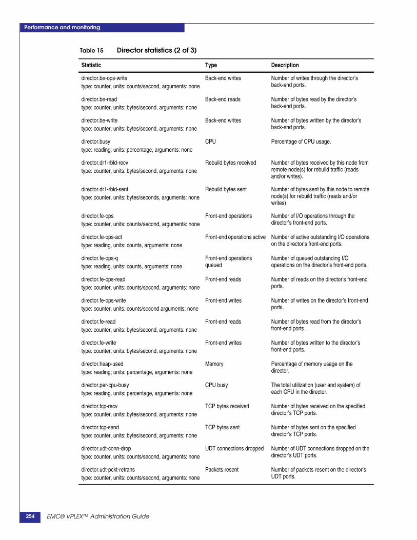
Performance and monitoring
director.be-ops-writetype: counter, units: counts/second, arguments: none
Back-end writes Number of writes through the director’sback-end ports.
director.be-readtype: counter, units: bytes/second, arguments: none
Back-end reads Number of bytes read by the director’sback-end ports.
director.be-writetype: counter, units: bytes/second, arguments: none
Back-end writes Number of bytes written by the director’sback-end ports.
director.busytype: reading; units: percentage, arguments: none
CPU Percentage of CPU usage.
director.dr1-rbld-recvtype: counter, units: bytes/second, arguments: none
Rebuild bytes received Number of bytes received by this node fromremote node(s) for rebuild traffic (readsand/or writes).
director.dr1-rbld-senttype: counter, units: bytes/seconds, arguments: none
Rebuild bytes sent Number of bytes sent by this node to remotenode(s) for rebuild traffic (reads and/orwrites)
director.fe-opstype: counter, units: counts/second, arguments: none
Front-end operations Number of I/O operations through thedirector’s front-end ports.
director.fe-ops-acttype: reading, units: counts, arguments: none
Front-end operations active Number of active outstanding I/O operationson the director’s front-end ports.
director.fe-ops-qtype: reading, units: counts, arguments: none
Front-end operationsqueued
Number of queued outstanding I/Ooperations on the director’s front-end ports.
director.fe-ops-readtype: counter, units: counts/second, arguments: none
Front-end reads Number of reads on the director’s front-endports.
director.fe-ops-writetype: counter, units: counts/second arguments: none
Front-end writes Number of writes on the director’s front-endports.
director.fe-readtype: counter, units: bytes/second, arguments: none
Front-end reads Number of bytes read from the director’sfront-end ports.
director.fe-writetype: counter, units: bytes/second, arguments: none
Front-end writes Number of bytes written to the director’sfront-end ports.
director.heap-usedtype: reading; units: percentage, arguments: none
Memory Percentage of memory usage on thedirector.
director.per-cpu-busytype: reading, units: percentage, arguments: none
CPU busy The total utilization (user and system) ofeach CPU in the director.
director.tcp-recvtype: counter, units: bytes/second, arguments: none
TCP bytes received Number of bytes received on the specifieddirector’s TCP ports.
director.tcp-sendtype: counter, units: bytes/second, arguments: none
TCP bytes sent Number of bytes sent on the specifieddirector’s TCP ports.
director.udt-conn-droptype: counter, units: counts/second, arguments: none
UDT connections dropped Number of UDT connections dropped on thedirector’s UDT ports.
director.udt-pckt-retranstype: counter, units: counts/second, arguments: none
Packets resent Number of packets resent on the director’sUDT ports.
Table 15 Director statistics (2 of 3)
Statistic Type Description
EMC® VPLEX™ Administration Guide254

Performance and monitoring
director.udt-recv-bytestype: counter, units: bytes/second, arguments: none
UDT bytes received Number of packets received on the director’sUDT ports.
director.udt-recv-dropstype: counter, units: counts/second, arguments: none
UDT received packetsdropped
Number of received packets dropped on thedirector’s UDT ports.
director.udt-recv-pcktstype: counter, units: counts/second, arguments: none
UTDT received packets Number of packets received on the director’sUDT ports.
director.udt-send-bytestype: counter, units: bytes/second, arguments: none
UDT sent bytes Number of bytes sent on the director’s UDTports.
director.udt-send-dropstype: counter, units: count/second, arguments: none
UDT sent packets dropped Number of sent packets dropped on thedirector’s UDT ports.
director.udt-send-pcktstype: counter, units: count/second, arguments: none
USDT sent packets Number of packets sent t on the director’sUDT ports.
Table 16 Directory statistics
Statistic Type Description
directory.ch-remote Cache coherence Internal EMC use only
directory.chk-total Cache coherence Internal EMC use only
directory.dir-total Cache coherence Internal EMC use only
directory.dr-remote Cache coherence Internal EMC use only
directory.ops-local Cache coherence Internal EMC use only
directory.ops-rem Cache coherence Internal EMC use only
Table 15 Director statistics (3 of 3)
Statistic Type Description
Table 17 Front-end director (fe-director) statistics
Statistic Type Description
fe-director.abortstype: counter, units: counts/second, arguments:none
Front-end operations Number of aborted I/O operations through thedirector’s front-end ports.
fe-director.caw-lattype: bucket, units: microsecond, arguments: none
CompareAndWriteoperations latency
CompareAndWrite latency in microseconds onthe specified director’s front-end ports. Thelatency bucket is reduced to three buckets from0 to maximum instead of 64 latency bucketscollected within the VPLEX firmware.
fe-director.read-lattype: bucket, units: microsecond, arguments: none
Front-end director readlatency
Read latency distribution in microseconds onthe director’s front-end ports.
fe-director.write-lattype: bucket, units: microsecond, arguments: none
Front-end director writelatency
Write latency distribution in microseconds onthe director’s front-end ports.
EMC® VPLEX™ Administration Guide 255

Performance and monitoring
Table 18 Front-end volume (fe-lu) statistics
Statistic Type Description
fe-lu.caw-lattype: bucket, units: microsecond,arguments:volume-id
CompareAndWriteoperations latency
CompareAndWrite latency in microseconds onthe specified front-end volume.
fe-lu.caw-mistype: counter, units: counts/second, arguments:volume-id
CompareAndWritemiscompares
Number of CompareAndWrite miscompares onthe specified front-end volume.
fe-lu.caw-opstype: counter, units: counts/second, arguments:volume-id
CompareAndWriteoperations
Number of CompareAndWrite operations onthe specified front-end volume.
fe-lu.opstype: counter, units: counts/second, arguments:volume-id
Front-end volumeoperations
Number of I/O operations on the specifiedfront-end volume.
fe-lu.readtype: counter, units: bytes/second, arguments:volume-id
Front-end volume reads Number of reads on the specified front-endvolume.
fe-lu.read-lattype: bucket, units: microsecond, arguments:volume-id
Front-end volume readlatency
Read latency distribution in microseconds onthe specified front-end volume.
fe-lu.writetype: counter, units: bytes/second, arguments:volume-id
Front-end volume writes Number of writes on the specified front-endvolume.
fe-lu.write-lattype: bucket, units: microsecond, arguments:volume-id
Front-end volume writelatency
Write latency distribution in microseconds onthe specified front-end volume.
Table 19 Front-end port (fe-prt) statistics (1 of 2)
Statistic Type Description
fe-prt.caw-lattype: bucket, units: microsecond, arguments:port#
CompareAndWriteoperations latency
CompareAndWrite latency in microseconds onthe specified front-end port.
fe-prt.caw-mistype: counter, units: counts/sec, arguments: port#
CompareAndWritemiscompares
Number of CompareAndWrite miscompares onthe specified front-end port.
fe-prt.caw-opstype: counter, units: counts/sec, arguments: port#
CompareAndWriteoperations
Number of CompareAndWrite operations onthe specified front-end port.
fe-prt.opstype: counter, units: counts/sec, arguments: port#
Front-end port operations Number of I/O operations on the specifiedfront-end FC port.
fe-prt.readtype: counter, units: bytes/sec, arguments: port#
Front-end port reads Number of bytes read from the specifiedfront-end FC port.
EMC® VPLEX™ Administration Guide256

Performance and monitoring
fe-prt.read-lattype: bucket, units: microsecond, arguments: port#
Front-end port read latency Read latency distribution in microseconds onthe specified front-end FC port.
fe-prt.writetype: counter, units: bytes/second, arguments:port#
Front-end port writes Number of bytes written to the specifiedfront-end FC port.
fe-prt.write-lattype: bucket, units: microsecond, arguments: port#
Front-end port writelatency
Write latency distribution in microseconds onthe specified front-end FC port.
Table 19 Front-end port (fe-prt) statistics (2 of 2)
Statistic Type Description
Table 20 Remote RAID (ramf) statistics
Statistic Type Description
ramf.cur-optype: reading, units: counts, arguments: none
Current op count Instantaneous count of remote RAIDoperations.
ramf.exp-optype: counter, units: counts/second, arguments: none
Remote operations Total number of remote IOPS.
ramf.exp-rdtype: counter, units: bytes/second, arguments: none
Remote reads Remote reads from another cluster to a diskor LUN at the local cluster.
ramf.exp-wrtype: counter, units: bytes/second, arguments: none
Remote writes Remote writes from another cluster to a diskor LUN at the local cluster.
ramf.imp-optype: counter, units: counts/second, arguments: none
Imported ops Number of operations that have beenrequested by a given director, regardless ofremote target.
ramf.imp-rdtype: counter, units: bytes/second, arguments: none
Imported reads Reads from the local cluster to a disk or LUNat a remote cluster.
ramf.imp-wrtype: counter, units: bytes/second, arguments: none
Imported writes Writes from the local cluster to a disk or LUNat a remote cluster.
Table 21 Remote data memory access (rdma) statistics
Statistic Type Description
rdma.cur-opstype: reading, units: counts, arguments: none
RDMA ops Instantaneous count of RDMA opsoutstanding.
rdma.readtype: counter, units: bytes/second, arguments: none
RDMA reads Number of RDMA read operations.
rdma.writetype: counter, units: bytes/second, arguments: none
RDMA writes Number of RDMA write operations.
EMC® VPLEX™ Administration Guide 257
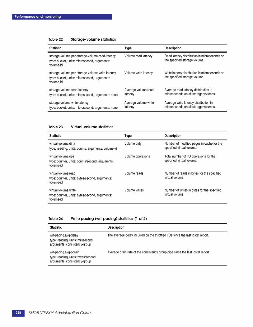
Performance and monitoring
Table 22 Storage-volume statistics
Statistic Type Description
storage-volume.per-storage-volume-read-latencytype: bucket, units: microsecond, arguments:volume-id
Volume read latency Read latency distribution in microseconds onthe specified storage volume.
storage-volume.per-storage-volume-write-latencytype: bucket, units: microsecond, arguments:volume-id
Volume write latency Write latency distribution in microseconds onthe specified storage volume.
storage-volume.read-latencytype: bucket, units: microsecond, arguments: none
Average volume readlatency
Average read latency distribution inmicroseconds on all storage volumes.
storage-volume.write-latencytype: bucket, units: microsecond, arguments: none
Average volume writelatency
Average write latency distribution inmicroseconds on all storage volumes.
Table 23 Virtual-volume statistics
Statistic Type Description
virtual-volume.dirtytype: reading, units: counts, arguments: volume-id
Volume dirty Number of modified pages in cache for thespecified virtual volume.
virtual-volume.opstype: counter, units: counts/second, arguments:volume-id
Volume operations Total number of I/O operations for thespecified virtual volume.
virtual-volume.readtype: counter, units: bytes/second, arguments:volume-id
Volume reads Number of reads in bytes for the specifiedvirtual volume.
virtual-volume.writetype: counter, units: bytes/second, arguments:volume-id
Volume writes Number of writes in bytes for the specifiedvirtual volume.
Table 24 Write pacing (wrt-pacing) statistics (1 of 2)
Statistic Description
wrt-pacing.avg-delaytype: reading, units: millisecond,arguments: consistency-group
The average delay incurred on the throttled I/Os since the last iostat report.
wrt-pacing.avg-pdraintype: reading, units: bytes/second,arguments: consistency-group
Average drain rate of the consistency group pipe since the last iostat report.
EMC® VPLEX™ Administration Guide258

Performance and monitoring
wrt-pacing.avg-pinputtype: reading, units: bytes/second,arguments: consistency-group
Average input rate of the consistency group pipe since the last iostat report.
wrt-pacing.is-throttlingtype: reading, units: counts, arguments:consistency-group
Has any I/O for this consistency group been throttled (delayed) since the last iostatreport?1- True. I/O has been throttled at least once since the last iostat report.0 - False. I/O has been never throttled.
wrt-pacing.peak-putiltype: reading, units: percent,arguments: consistency-group
Maximum pipe utilization observed since the last iostat report.
Table 24 Write pacing (wrt-pacing) statistics (2 of 2)
Statistic Description
Table 25 Consistency-group (cg) statistics (1 of 2)
Statistic Description
cg.closuretype: bucket, units: microsecond,arguments: consistency-group
A distribution of time taken to complete closure requests over the last sampling period.
cg.delta-utiltype: reading, units: percentage,arguments: consistency-group
The average capacity utilization of closed deltas (how full the deltas were when aclosure was requested) over the last sampling period.
cg.drain-lattype: bucket, units: microsecond,arguments: consistency-group
A distribution of time taken to drain deltas out of a asynchronous consistency-grouppipe over the last sampling period. The time taken to drain a delta is the sum of theexchange, write and commit latencies.
cg.exch-bytestype: counter, units: bytes/second,arguments: consistency-group
The number of bytes received from other cluster(s) at this director over the lastsampling period.
cg.exch-lattype: bucket, units: microsecond,arguments: consistency-group
A distribution of time spent in the exchange phase when processing deltas over thelast sampling period.
cg.exch-pagestype: counter, units: counts/second,arguments: consistency-group
The number of pages received from other cluster(s) at this director over the lastsampling period.
cg.input-bytestype: counter, units: bytes/second,arguments: consistency-group
The number of incoming bytes to the asynchronous consistency-group pipe over thelast sampling period.
cg.iput-opstype: counter, units: counts/second,arguments: consistency-group
The number of inbound-data operations to an asynchronous consistency-group pipeover the last sampling period.
cg.inter-closuretype: bucket, units: microsecond,arguments: consistency-group
A distribution of time between consecutive closure requests over the last samplingperiod.
cg.outOfDate-countertype: counter, units: counts/second,arguments: consistency-group
The number of writes over the last sampling period for which an underlying DR1 legwas out of date.
EMC® VPLEX™ Administration Guide 259

Performance and monitoring
cg.pipe-utiltype: reading, units: percentage,arguments: consistency-group
The average utilization (number of outstanding deltas) of the asynchronousconsistency-group pipe over the last sampling period.
cg.write-bytestype: counter, units: bytes/second,arguments: consistency-group
The number of bytes written to the back end at this director over the last samplingperiod.
cg.write-lattype: bucket, units:microsecond,arguments: consistency-group
A distribution of duration spent in the write phase when processing deltas over the lastsampling period.
cg.write-pagestype: counter, units: counts/second,arguments: consistency-group
The number of pages written to the back end at this director over the last samplingperiod.
Table 25 Consistency-group (cg) statistics (2 of 2)
Statistic Description
Table 26 RecoverPoint volume statistics (rp-spl-vol)
Statistic Description
rp-spl-vol.write-activetype: reading, units: counts, arguments:vol-id
The current number of outstanding writes in the splitter for a specific volume.
rp-spl-vol.-write-opstype: counter, units: counts/second,arguments: vol-id
Number of writes that have been processed by the splitter for a specific volume.
rp-spl-vol.-writetype: counter, units: bytes/second,arguments: vol-id
The quantity of write data that has been split for a specific volume.
rp-spl-vol.write-lattype: bucket, units: microsecond,arguments: vol-id
Latency from when a write is sent to the splitter to when it is sent down the normal BEI/O stack. Measures SCSI round-trip time to get the write data into the memory of theRPA.
Table 27 RecoverPoint splitter statistics (rp-spl-node)
Statistic Description
rp-spl-node.write-activetype: reading, units: counts, arguments:none
Current number of outstanding writes in the splitter.Tracks split I/Os from when they enter the splitter until they finish in the BE perdirector..
rp-spl-node.write-opstype: counter, units: counts/second,arguments: none
Number of writes that have been processed by the splitter.
rp-spl-node.writetype: counter, units: bytes/second,arguments: none
Quantity of write data that has been split.
rp-spl-node.write-lattype: bucket, units: microsecond,arguments: none
Latency from when a write is sent to the splitter to when it is sent down the normalBE I/O stack. Measures SCSI round-trip time to get the write data into the memory ofthe RPA..
EMC® VPLEX™ Administration Guide260

Performance and monitoring
Table 28 IP WAN COM (ip-com-port) statistics
Statistic Type Description
ip-com-port.avg-latencytype: reading, units: microsecond,arguments: port-name
IP WAN COM portaverage latency
Total latency/number of Keepaliveack round trips,including wire and COM latency in microseconds on thisIP WAN COM port.
Note: Not useful for describing wire latency. Theselatency values reflect the quality of service over a WANCOM port. Values include: wire latency, COM latencyincreases, and retransmitted packets due to packet dropson the wire. Retransmitted packets increase themaximum and average latency values.These values normalize once the packet drops are nolonger occurring.
ip-com-port.max-latencytype: reading, units: microsecond,arguments: port-name
IP WAN COM portmaximum latency
Keepaliveack round trip, including wire and COM latencyin microseconds on this IP WAN COM port.
ip-com-port.min-latencytype: reading, units: microsecond,arguments: port-name
IP WAN COM portminimum latency
Keepaliveack round trip, including wire and COM latencyin microseconds on this IP WAN COM port.
ip-com-port.pckt-retranstype: counter, units: counts/second,arguments: port-name
IP WAN COM Portpackets resent
Number of packets resent on this IP WAN COM port.
ip-com-port.recv-bytestype: counter, units: bytes/second,arguments: port-name
IP WAN COM Portbytes received
Number of bytes received through UDT on this IP WANCOM port.
ip-com-port.recv-dropstype: counter, units: counts/second,arguments: port-name
IP WAN COM Portreceived packetsdropped
Number of received packets dropped on this IP WANCOM port.
ip-com-port.recv-pcktstype: counter, units: counts/second,arguments: port-name
IP WAN COM Portpackets received
Number of packets received through UDT on this IP WANCOM port.
ip-com-port.send-bytestype: counter, units: bytes/second,arguments: port-name
IP WAN COM Portbytes sent
Number of bytes sent through UDT on this IP WAN COMport.
ip-com-port.send-dropstype: counter, units: counts/second,arguments: port-name
IP WAN COM Port sentpackets dropped
Number of sent packets dropped on this IP WAN COMport.
ip-com-port.send-pcktstype: counter, units: counts/second,arguments: port-name
IP WAN COM Portpackets sent
Number of packets sent through UDT on this IP WANCOM port.
EMC® VPLEX™ Administration Guide 261
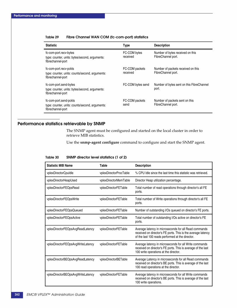
Performance and monitoring
Performance statistics retrievable by SNMPThe SNMP agent must be configured and started on the local cluster in order toretrieve MIB statistics.
Use the snmp-agent configure command to configure and start the SNMP agent.
Table 29 Fibre Channel WAN COM (fc-com-port) statistics
Statistic Type Description
fc-com-port.recv-bytestype: counter, units: bytes/second, arguments:fibrechannel-port
FC-COM bytesreceived
Number of bytes received on thisFibreChannel port.
fc-com-port.recv-pcktstype: counter, units: counts/second, arguments:fibrechannel-port
FC-COM packetsreceived
Number of packets received on thisFibreChannel port.
fc-com-port.send-bytestype: counter, units: bytes/second, arguments:fibrechannel-port
FC-COM bytes send Number of bytes sent on this FibreChannelport.
fc-com-port.send-pcktstype: counter, units: counts/second, arguments:fibrechannel-port
FC-COM packetssend
Number of packets sent on thisFibreChannel port.
Table 30 SNMP director level statistics (1 of 2)
Statistic MIB Name Table Description
vplexDirectorCpuIdle vplexDirectorProcTable % CPU Idle since the last time this statistic was retrieved.
vplexDirectorHeapUsed vplexDirectorMemTable Director Heap utilization percentage.
vplexDirectorFEOpsRead vplexDirectorFETable Total number of read operations through director's all FEports.
vplexDirectorFEOpsWrite vplexDirectorFETable Total number of Write operations through director's all FEports.
vplexDirectorFEOpsQueued vplexDirectorFETable Number of outstanding I/Os queued on director's FE ports.
vplexDirectorFEOpsActive vplexDirectorFETable Total number of outstanding I/Os active on director's FEports.
vplexDirectorFEOpsAvgReadLatency vplexDirectorFETable Average latency in microseconds for all Read commandsreceived on director's FE ports. This is the average latencyof the last 100 reads performed at the director.
vplexDirectorFEOpsAvgWriteLatency vplexDirectorFETable Average latency in microseconds for all Write commandsreceived on director's FE ports. This is average of the last100 write operations at the director.
vplexDirectorBEOpsAvgReadLatency vplexDirectorBETable Average Latency in microseconds for all Read commandsreceived on director's BE ports. This is average of the last100 read operations at the director.
vplexDirectorBEOpsAvgWriteLatency vplexDirectorFETable Average latency in microseconds for all Write commandsreceived on director's BE ports. This is average of the last100 write operations.
EMC® VPLEX™ Administration Guide262

Performance and monitoring
vplexDirectorFEBytesRead vplexDirectorFETable Total number of bytes read on the director's FE ports.
vplexDirectorFEBytesWrite vplexDirectorFETable Total number of bytes Written on the director's FE ports.
vplexDirectorBEOpsRead vplexDirectorBETable Total number of read operations through director's all BEports.
vplexDirectorBEOpsWrite vplexDirectorBETable Total number of Write operations through director's all BEports.
vplexDirectorBEBytesRead vplexDirectorBETable Total number of bytes read on the director's BE ports.
vplexDirectorBEBytesWrite vplexDirectorBETable Total number of bytes written on the director's BE ports.
Table 31 SNMP port level statistics
Statistic MIB Name Table Description
vplexDirectorFEPortBytesRead vplexDirectorFEPortTable Number of bytes read on this FE port.
vplexDirectorFEPortBytesWrite vplexDirectorFEPortTable Number of bytes written on this FE port.
vplexDirectorBEPortBytesRead vplexDirectorBEPortTable Number of bytes read through this BE port.
vplexDirectorBEPortBytesWrite vplexDirectorBEPortTable Number of bytes written through this BE port.
Table 30 SNMP director level statistics (2 of 2)
EMC® VPLEX™ Administration Guide 263

Performance and monitoring
EMC® VPLEX™ Administration Guide264

This glossary contains terms related to VPLEX federated storage systems. Many ofthese terms are used in this manual.
AAccessAnywhere The breakthrough technology that enables VPLEX clusters to provide access to
information between clusters that are separated by distance.
active/active A cluster with no primary or standby servers, because all servers can run applicationsand interchangeably act as backup for one another.
Active Directory A directory service included in most Windows Server operating systems. ADauthenticates and authorizes users and computers in a network of Windows domaintype.
active/passive A powered component that is ready to operate upon the failure of a primarycomponent.
array A collection of disk drives where user data and parity data may be stored. Devicescan consist of some or all of the drives within an array.
asynchronous Describes objects or events that are not coordinated in time. A process operatesindependently of other processes, being initiated and left for another task beforebeing acknowledged.
For example, a host writes data to the blades and then begins other work while thedata is transferred to a local disk and across the WAN asynchronously. See also“synchronous.”
Bbandwidth The range of transmission frequencies a network can accommodate, expressed as the
difference between the highest and lowest frequencies of a transmission cycle. Highbandwidth allows fast or high-volume transmissions.
backend port VPLEX director port connected to storage arrays (acts as an initiator).
bias When a cluster has the bias for a given DR1, it continues to service I/O to volumes onthat cluster if connectivity to the remote cluster is lost (due to cluster partition or
Glossary
EMC® VPLEX™ Administration Guide 265

Glossary
cluster failure). The bias for a specific volume is determined by the detach rules forthe volume, the detach rules for the consistency group (if the volume is a member of aconsistency group) and VPLEX Witness (if VPLEX Witness is deployed).
bit A unit of information that has a binary digit value of either 0 or 1.
block The smallest amount of data that can be transferred following SCSI standards, whichis traditionally 512 bytes. Virtual volumes are presented to users as a contiguous listsof blocks.
block size The actual size of a block on a device.
byte Memory space used to store eight bits of data.
Ccache Temporary storage for recent writes and recently accessed data. Disk data is read
through the cache so that subsequent read references are found in the cache.
cache coherency Managing the cache so data is not lost, corrupted, or overwritten. With multipleprocessors, data blocks may have several copies, one in the main memory and one ineach of the cache memories. Cache coherency propagates the blocks of multiple usersthroughout the system in a timely fashion, ensuring the data blocks do not haveinconsistent versions in the different processors caches.
cluster Two or more VPLEX directors forming a single fault-tolerant cluster, deployed as oneto four engines.
cluster ID The identifier for each cluster in a multi-cluster deployment. The ID is assignedduring installation.
cluster deployment ID A numerical cluster identifier, unique within a VPLEX cluster. By default, VPLEXclusters have a cluster deployment ID of 1. For multi-cluster deployments, all but onecluster must be reconfigured to have different cluster deployment IDs.
cluster IP seed The VPLEX IP seed is used to generate the IP addresses used by the internalcomponents of the VPLEX. For more information about components and their IPaddresses, refer to EMC VPLEX Installation and Setup Guide. Cluster ID is used bythe virtualization software (inter director messaging, cluster identification).
clustering Using two or more computers to function together as a single entity. Benefits includefault tolerance and load balancing, which increases reliability and up time.
COM The intra-cluster communication (Fibre Channel). The communication used for cachecoherency and replication traffic.
command lineinterface (CLI)
Method of operating system or application software by typing commands to performspecific tasks.
consistency group A VPLEX structure that groups together virtual volumes and applies the same detachand failover rules to all member volumes. Consistency groups ensure the commonapplication of a set of properties to the entire group. Create consistency groups forsets of volumes that require the same I/O behavior in the event of a link failure. Thereare two types of consistency groups:
EMC® VPLEX™ Administration Guide266

Glossary
◆ Synchronous Consistency Groups - Use write-through (synchronous) cachemode to write data to the underlying storage before an acknowledgement is sentto the host. Dependent on latency between clusters and the application'stolerance of the latency
◆ Asynchronous Consistency Groups - Use write-back (asynchronous) cache modeto write protect data by mirroring it to the memory another director in the cluster.Data is destaged asynchronously to the back-end storage arrays. Writes areacknowledged once the data has been committed to disk in write order
continuity ofoperations (COOP)
The goal of establishing policies and procedures to be used during an emergency,including the ability to process, store, and transmit data before and after.
controller A device that controls the transfer of data to and from a computer and a peripheraldevice.
Ddata sharing The ability to share access to the same data with multiple servers regardless of time
and location.
detach rule Predefined rules that determine which cluster continues I/O when connectivitybetween clusters is lost. A cluster loses connectivity to its peer cluster due to clusterpartition or cluster failure.
Detach rules are applied at two levels; to individual volumes, and to consistencygroups. If a volume is a member of a consistency group, the group detach ruleoverrides the rule set for the individual volumes. Note that all detach rules may beoverridden by Cluster Witness, if Cluster Witness is deployed.
device A combination of one or more extents to which you add specific RAID properties.Local devices use storage from only one cluster. In VPLEX Metro and Geoconfigurations, distributed devices use storage from both clusters.
director A CPU module that runs GeoSynchrony, the core VPLEX software. There are twodirectors (A and B) in each engine, and each has dedicated resources and is capable offunctioning independently.
dirty data The write-specific data stored in the cache memory that has yet to be written to disk.
disaster recovery (DR) The ability to restart system operations after an error, preventing data loss.
disk cache A section of RAM that provides cache between the disk and the CPU. RAMs accesstime is significantly faster than disk access time; therefore, a disk-caching programenables the computer to operate faster by placing recently accessed data in the diskcache.
distributed device A RAID 1 device whose mirrors are in different VPLEX clusters.
distributed file system(DFS)
Supports the sharing of files and resources in the form of persistent storage over anetwork.
distributed RAID1device (DR1)
Distributed devices have physical volumes at both clusters in a VPLEX Metro orVPLEX Geo configuration for simultaneous active/active read/write access usingAccessAnywhere™
EMC® VPLEX™ Administration Guide 267
Glossary
Eengine Consists of two directors, management modules, and redundant power. Unit of scale
for VPLEX configurations. Single = 1 engine, dual = 2 engines, Quad = 4 engines percluster.
Ethernet A Local Area Network (LAN) protocol. Ethernet uses a bus topology, meaning alldevices are connected to a central cable, and supports data transfer rates of between10 megabits per second and 10 gigabits per second. For example, 100 Base-T supportsdata transfer rates of 100 Mb/s.
event A log message that results from a significant action initiated by a user or the system.
extent All or a portion (range of blocks) of a storage volume.
Ffailover Automatically switching to a redundant or standby device, system, or data path upon
the failure or abnormal termination of the currently active device, system, or datapath.
fault domain A set of components that share a single point of failure. For VPLEX, the concept thatevery component of a Highly Available system is separated, so that if a fault occurs inone domain, it will not result in failure in other domains to which it is connected.
fault tolerance Ability of a system to keep working in the event of hardware or software failure,usually achieved by duplicating key system components.
Fibre Channel (FC) A protocol for transmitting data between computer devices. Longer distance requiresthe use of optical fiber; however, FC also works using coaxial cable and ordinarytelephone twisted pair media. Fibre channel offers point-to-point, switched, and loopinterfaces. Used within a SAN to carry SCSI traffic.
Fibre Channel over IP(FCIP)
Combines Fibre Channel and Internet protocol features to connect SANs ingeographically distributed systems.
field replaceable unit(FRU)
A unit or component of a system that can be replaced on site as opposed to returningthe system to the manufacturer for repair.
firmware Software that is loaded on and runs from the flash ROM on the VPLEX directors.
front end port VPLEX director port connected to host initiators (acts as a target).
Ggeographically
distributed systemA system physically distributed across two or more geographically separated sites.The degree of distribution can vary widely, from different locations on a campus or ina city to different continents.
gigabit (Gb or Gbit) 1,073,741,824 (2^30) bits. Often rounded to 10^9.
gigabit Ethernet The version of Ethernet that supports data transfer rates of 1 Gigabit per second.
gigabyte (GB) 1,073,741,824 (2^30) bytes. Often rounded to 10^9.
EMC® VPLEX™ Administration Guide268

Glossary
global file system(GFS)
A shared-storage cluster or distributed file system.
Hhost bus adapter
(HBA)An I/O adapter that manages the transfer of information between the host computersbus and memory system. The adapter performs many low-level interface functionsautomatically or with minimal processor involvement to minimize the impact on thehost processors performance.
Iinput/output (I/O) Any operation, program, or device that transfers data to or from a computer.
internet Fibre Channelprotocol (iFCP)
Connects Fibre Channel storage devices to SANs or the Internet in geographicallydistributed systems using TCP.
intranet A network operating like the World Wide Web but with access restricted to a limitedgroup of authorized users.
internet smallcomputer system
interface (iSCSI)
A protocol that allows commands to travel through IP networks, which carries datafrom storage units to servers anywhere in a computer network.
I/O (input/output) The transfer of data to or from a computer.
Kkilobit (Kb) 1,024 (2^10) bits. Often rounded to 10^3.
kilobyte (K or KB) 1,024 (2^10) bytes. Often rounded to 10^3.
Llatency Amount of time it requires to fulfill an I/O request.
LDAP Lightweight Directory Access Protocol, an application protocol that accesses andmaintains distributed directory information services over an IP network.
load balancing Distributing the processing and communications activity evenly across a system ornetwork so no single device is overwhelmed. Load balancing is especially importantwhen the number of I/O requests issued is unpredictable.
local area network(LAN)
A group of computers and associated devices that share a common communicationsline and typically share the resources of a single processor or server within a smallgeographic area.
local device A combination of one or more extents to which you add specific RAID properties.Local devices use storage from only one cluster.
logical unit number(LUN)
Virtual storage to which a given server with a physical connection to the underlyingstorage device may be granted or denied access. LUNs are used to identify SCSIdevices, such as external hard drives, connected to a computer. Each device isassigned a LUN number which serves as the device's unique address.
EMC® VPLEX™ Administration Guide 269

Glossary
Mmegabit (Mb) 1,048,576 (2^20) bits. Often rounded to 10^6.
megabyte (MB) 1,048,576 (2^20) bytes. Often rounded to 10^6.
metadata Information about data, such as data quality, content, and condition.
metavolume A storage volume used by the system that contains the metadata for all the virtualvolumes managed by the system. There is one metadata storage volume per cluster.
Metro-Plex Two VPLEX Metro clusters connected within metro (synchronous) distances,approximately 60 miles or 100 kilometers.
mirroring The writing of data to two or more disks simultaneously. If one of the disk drivesfails, the system can instantly switch to one of the other disks without losing data orservice. RAID 1 provides mirroring.
miss An operation where the cache is searched but does not contain the data, so the datainstead must be accessed from disk.
Nnamespace A set of names recognized by a file system in which all names are unique.
network System of computers, terminals, and databases connected by communication lines.
network architecture Design of a network, including hardware, software, method of connection, and theprotocol used.
network-attachedstorage (NAS)
Storage elements connected directly to a network.
network partition When one site loses contact or communication with another site.
OOpen LDAP Open source implementation of the Lightweight Directory Access Protocol (LDAP).
Pparity checking Checking for errors in binary data. Depending on whether the byte has an even or
odd number of bits, an extra 0 or 1 bit, called a parity bit, is added to each byte in atransmission. The sender and receiver agree on odd parity, even parity, or no parity. Ifthey agree on even parity, a parity bit is added that makes each byte even. If theyagree on odd parity, a parity bit is added that makes each byte odd. If the data istransmitted incorrectly, the change in parity will reveal the error.
partition A subdivision of a physical or virtual disk, which is a logical entity only visible to theend user, not any of the devices.
RRAID The use of two or more storage volumes to provide better performance, error
recovery, and fault tolerance.
EMC® VPLEX™ Administration Guide270

Glossary
RAID 0 A performance-orientated striped or dispersed data mapping technique. Uniformlysized blocks of storage are assigned in regular sequence to all of the arrays disks.Provides high I/O performance at low inherent cost. No additional disks arerequired. The advantages of RAID 0 are a very simple design and an ease ofimplementation.
RAID 1 Also called mirroring, this has been used longer than any other form of RAID. Itremains popular because of simplicity and a high level of data availability. Amirrored array consists of two or more disks. Each disk in a mirrored array holds anidentical image of the user data. RAID 1 has no striping. Read performance isimproved since either disk can be read at the same time. Write performance is lowerthan single disk storage. Writes must be performed on all disks, or mirrors, in theRAID 1. RAID 1 provides very good data reliability for read-intensive applications.
RAID leg A copy of data, called a mirror, that is located at a user's current location.
rebuild The process of reconstructing data onto a spare or replacement drive after a drivefailure. Data is reconstructed from the data on the surviving disks, assumingmirroring has been employed.
RecoverPointAppliance (RPA)
Hardware that manages all aspects of data protection for a storage group, includingcapturing changes, maintaining the images in the journal volumes, and performingimage recovery.
RecoverPoint cluster All connected RecoverPoint Appliances on both sides of the replication.
RecoverPoint site All RecoverPoint entities on one side of the replication.
Recovery PointObjective
See “RPO” on page 271.
Recovery TimeObjective
See “RTO” on page 272.
redundancy The duplication of hardware and software components. In a redundant system, if acomponent fails then a redundant component takes over, allowing operations tocontinue without interruption.
reliability The ability of a system to recover lost data.
remote directmemory access
(RDMA)
Allows computers within a network to exchange data using their main memories andwithout using the processor, cache, or operating system of either computer.
Replication set When RecoverPoint is deployed, a production source volume and one or more replicavolume(s) to which it replicates.
RPO Recovery Point Objective. The time interval between the point of failure of a storagesystem and the expected point in the past, to which the storage system is capable ofrecovering customer data. Informally, RPO is a maximum amount of data loss thatcan be tolerated by the application after a failure. The value of the RPO is highlydependent upon the recovery technique used. For example, RPO for backups istypically days; for asynchronous replication minutes; and for mirroring orsynchronous replication seconds or instantaneous.
EMC® VPLEX™ Administration Guide 271
Glossary
RTO Recovery Time Objective. Not to be confused with RPO, RTO is the time durationwithin which a storage solution is expected to recover from failure and beginservicing application requests. Informally, RTO is the longest tolerable applicationoutage due to a failure of a storage system. RTO is a function of the storagetechnology. It may measure in hours for backup systems, minutes for a remotereplication, and seconds (or less) for a mirroring.
Sscalability Ability to easily change a system in size or configuration to suit changing conditions,
to grow with your needs.
simple networkmanagement
protocol (SNMP)
Monitors systems and devices in a network.
site ID The identifier for each cluster in a multi-cluster plex. By default, in anon-geographically distributed system the ID is 0. In a geographically distributedsystem, one clusters ID is 1, the next is 2, and so on, each number identifying aphysically separate cluster. These identifiers are assigned during installation.
SLES SUSE Linux Enterprise Server is a Linux distribution supplied by SUSE and targetedat the business market.
small computersystem interface
(SCSI)
A set of evolving ANSI standard electronic interfaces that allow personal computersto communicate faster and more flexibly than previous interfaces with peripheralhardware such as disk drives, tape drives, CD-ROM drives, printers, and scanners.
splitter EMC RecoverPoint write-splitting technology built into GeoSynchrony starting in 5.1.
storage area network(SAN)
A high-speed special purpose network or subnetwork that interconnects differentkinds of data storage devices with associated data servers on behalf of a largernetwork of users.
storage view A combination of registered initiators (hosts), front-end ports, and virtual volumes,used to control a hosts access to storage.
storage volume A Logical Unit Number (LUN) or unit of storage presented by the back end array.
stripe depth The number of blocks of data stored contiguously on each storage volume in a RAID0 device.
striping A technique for spreading data over multiple disk drives. Disk striping can speed upoperations that retrieve data from disk storage. Data is divided into units anddistributed across the available disks. RAID 0 provides disk striping.
synchronous Describes objects or events that are coordinated in time. A process is initiated andmust be completed before another task is allowed to begin.
For example, in banking two withdrawals from a checking account that are started atthe same time must not overlap; therefore, they are processed synchronously. See also“asynchronous.”
EMC® VPLEX™ Administration Guide272
Glossary
Tthroughput 1. The number of bits, characters, or blocks passing through a data communication
system or portion of that system.
2. The maximum capacity of a communications channel or system.
3. A measure of the amount of work performed by a system over a period of time. Forexample, the number of I/Os per day.
tier A collection of storage volumes that are equivalent in performance and RAIDprotection attributes.
tool commandlanguage (TCL)
A scripting language often used for rapid prototypes and scripted applications.
transfer size The size of the region in cache used to service data migration. The area is globallylocked, read at the source, and written at the target. Transfer-size can be as small as 40K, as large as 128 M, and must be a multiple of 4 K. The default value is 128 K.
A larger transfer-size results in higher performance for the migration, but maynegatively impact front-end I/O. This is especially true for VPLEX Metro migrations.Set a large transfer-size for migrations when the priority is data protection ormigration performance.
A smaller transfer-size results in lower performance for the migration, but creates lessimpact on front-end I/O and response times for hosts. Set a smaller transfer-size formigrations when the priority is front-end storage response time.
transmission controlprotocol/Internetprotocol (TCP/IP)
The basic communication language or protocol used for traffic on a private networkand the Internet.
Uuninterruptible power
supply (UPS)A power supply that includes a battery to maintain power in the event of a powerfailure.
universal uniqueidentifier (UUID)
A 64-bit number used to uniquely identify each VPLEX director. This number isbased on the hardware serial number assigned to each director.
Vvirtualization A layer of abstraction implemented in software that servers use to divide available
physical storage into storage volumes or virtual volumes.
virtual volume Unit of storage presented by the VPLEX front end ports to hosts. A virtual volumelooks like a contiguous volume, but can be distributed over two or more storagevolumes.
wide area network(WAN)
A geographically dispersed telecommunications network. This term distinguishes abroader telecommunication structure from a local area network (LAN).
world wide name(WWN)
A specific Fibre Channel Name Identifier that is unique worldwide and representedby a 64-bit unsigned binary value.
write-back mode A caching technique where the completion of a write request is communicated assoon as the data is in cache, with writes to disk occurring at different times.
EMC® VPLEX™ Administration Guide 273

Glossary
Write-back is faster than write-through, but risks a system failure before the data issafely written to disk.
write-through mode A caching technique in which the completion of a write request is communicatedonly after data is written to disk. This is almost equivalent to non-cached systems, butwith data protection.
EMC® VPLEX™ Administration Guide274
Index
AAbout
meta-volumes 38performance monitoring 234transfer-size 111
addingto a rule set 73
addvirtualvolume, export view 87attaching
rule sets, 74rule sets, local RAIDs 76
automatic rebuilds 94
Bbatch migrations 109
cancel 112check migration plan 110clean 114create migration plan 109modify batch migration plan 111monitor 112pause/resume 111prerequisites 109remove 115start 111status 113transfer-size 111
battery conditioning 54typical monthly calendar 54when to stop a cycle 56
Ccache vaulting
about 198recovery after vault 203successful recovery 204unsuccessful recovery 204vaulting process 201
call-home notificationsabout 57customized call-home events 57event severity 57
CAWCompareAndWrite 61display storage view setting 62display system default setting 62enable/disable as default 63enable/disable for storage view 62Example monitor 240statistics 63
CLI? wildcard 23* wildcard 23** wildcard 23accessing help 26context tree 15, 17display available commands 21display command arguments 23executing commands 21Log in 14Log out 14log out 14login 14page output 22positional arguments 25setting logging threshold 30Tab completion 22using commands 21-verbose and --help arguments 25viewing command history 26
CLI commandscd 19globbing 24ls 18popd 17positional arguments 25pushd 17tree 19verbose and --help arguments 25wildcards 23
CLI context tree 17CLI workspace
command history 26console logging 30customize the login banner 30remove login banner 30
EMC® VPLEX™ Administration Guide 275

Index
set window width 31command history, viewing 26configurations
rule sets, verifying 76consistency groups
add volumes 149apply a detach rule 154asynchronous 133
active/active 136active/passive 134RPO 136
create 146delete 156display 157display descriptions 161enable local-read-override 155properties 137
active cluster 143auto-resume-at-loser 141cache mode 137default closeout-time 144detach-rule 140local-read-override 140maximum-queue-depth 144modify properties 152recoverpoint-enabled 142storage-at-clusters 139virtual-volumes 142visibility 138
remove volumes 150resolve conflicting detach 166resume I/O after rollback 167resume I/O at the losing cluster 169set visibility 153synchronous 130
global visibility 132local visibility 132
console sink 240copying
rule sets 78create a virtual volume 85
Ddata
migration, batching 109migration, multiple RAIDs 109
Data loss failure mode 180data migrations
about 100batch migrations 100general steps 100one time migrations 100prerequisites 101
disallowing RAID rebuilds 94Display
consistency-groupsadvanced properties 158names 157operational status 158
monitors 242
distributed devices 79add local mirror 90create from exported volume 93create virtual volume 85enable/disable auto-resume 96enable/disable device rebuilds 94how to create 79remove local mirror 92resume I/O conflicting detach 98resume I/O during outage 97
Eexecuting CLI commands 21export
view addvirtualvolume 87
Ffile rotation 237
Hhelp command
CLI 26help, accessing in CLI 26
Llink failure recovery
rule sets, adding 73Log in to CLI 14Log out from CLI 14logging threshold, setting 30logging volumes
add a mirror 68create 68delete 69size 67
Mmeta-volumes
about 38backup
VPLEX Local 42VPLEX Metro or Geo 44
change name 47create 40delete 48display 49display fields 49move 46performance/availability requirements 38
migrating datamultiple RAIDs 109
monitor sinkdelate 241
monitor sinks 240
NNames 24
EMC® VPLEX™ Administration Guide276

Index
VPLEX components 24
Oone-time migration
cancel 106clean 107commit 107monitor 105pause/resume 106remove 108start 104
option-sets context 121
Pperfomance monitor
create 237Performance monitoring
custom monitors 234file rotation 237perpetual monitors 234preconfigured monitors 234VPLEX GUI 235
performance monitoringabout 234add console sink 240add file sink 241add sinks 240configure SNMP 249consistency groups 248create a monitor using the CLI 237create monitor 238delete monitor sink 241display monitors 242display statistics 251force an immediate poll 245manage sinks 245polling 244procedure 237SNMP 248statistics 251using the VPLEX CLI 236
Perpetual monitors 234port groups 118port-group
change MTU size 126port-groups context 121
RRAIDs
attaching rule sets 76automatic rebuilds, allowing/disallowing 94migrating (batching) 109
rebuilddisplay 94
RebuildsPerformance 103
rebuilds 102automatic, disallowing 94performance 103
thin provisioned storage 102RecoverPoint
configuration/operation guidelines 223configurations 212consistency groups 225management tools 230repository volume 223storage failures 226terminology and concepts 209VPLEX Local and RecoverPoint CDP 214VPLEX Local and RecoverPoint CRR/CLR 215VPLEX Metro and RecoverPoint CDP 216VPLEX Metro and RecoverPoint CRR/CLR 216VPLEX NDU 225VPLEX volumes 224zoning 227
removingsingle rule sets 77
Resolve a conflicting detach 166rule sets
adding rules 73attaching to distributed RAIDs 74attaching to local RAIDs 76attaching to RAIDs 74configuration, verifying 76copying 78removing 77
rule-setsabout 70add a rule 73attach to a device 74auto-resume 71best practices 71copy 78default 71delete 78detach 77local devices 72modify a device’s 75remove all rules 77verify 76
Ssetting
logging threshold for the CLI 30SNMP 262start snmp agent 262statistics 251, 262
back-end fibre channel port 243, 253cache 253consistency group (wof-throttle) 258, 259, 260director 253directory 255Fibre Channel WAN COM (fc-com-port) 262front-end director 255front-end LU 256front-end port 256IP WAN COM (ip-com-port) 261remote data memory access 257remote RAID 257
EMC® VPLEX™ Administration Guide 277

Index
retrievable by SNMP 262storage-volume 258virtual-volume 258, 259, 260, 261, 262
subnets context 120system (SYR) reporting
about 58
TThin provisioning 102
UUser accounts
add 32change password 34delete 33reset 34
Vverification
rule set configurations 76view
addvirtualvolume 87virtual volume
create 85export to hosts 87export to remote host 89
volume-set add-virtual-volumes 146VPLEX Witness
deploment 172display status
cluster isolation 193cluster link restored 195cluster-1 failure 191cluster-2 failure 192dual failure with DU 193inter-cluster link failure 191
enable/disable 184failures 176
Metro Systems without Witness 175VPLEX Geo
with VPLEX Witness 180
without VPLEX Witness 178with VPLEX Witness 176
iCLI context 183idisplay status 185
dual failures 189normal operation 187single failures 187single failures with DU 190
installation considerations 183irenew security certificate 184
WWAN ports 117
change a port group configuration 123change a port’s IP address 126change port-group’s MTU 126CLI contexts 119
Geo configuration rules 118option-sets context 121port-groups context 121subnets context 120
EMC® VPLEX™ Administration Guide278