emd sw8 - operation manual · emd sw8 - operation manual section 5 - air system 500 - general 500 -...
TRANSCRIPT

EMD SW8 - Operation Manual
Manual Cover
DIESEL LOCOMOTIVE
OPERATING MANUAL NO. 2313
for
SWITCHER LOCOMOTIVE
MODELS SW8 AND SW9
and
TRANSFER LOCOMOTIVE
MODELS TR5 AND TR6
1st Edition January, 1951
Price $2.50
ELECTRO-MOTIVE DIVISION
General Motors Corporation LA GRANGE, ILLINOIS, U.S.A
INTRODUCTION
This manual has been produced to assist the engineman in the operation of Switcher and Transfer locomotive Models SW8, SW9, TR5, and TR6. The information contained includes the basic equipment as well as the most commonly used "extras."
The book is divided into seven sections with the first six sections containing information applicable to all of the above named models. Section 7 is devoted exclusively to a description and discussion of the operation of the TR5 and TR6 Transfer locomotives.
The principle articles of each section are numbered consecutively for ready reference, as is each page of the section. Articles and pages are numbered in the 100 series type of numbering. A page in the 300's is in Section 3 as is any article numbered in the 300's.
SW8 Locomotive -- 800 HP
file:///C|/emd/sw8-op.html (1 of 7)10/4/2011 10:27:34 PM

EMD SW8 - Operation Manual
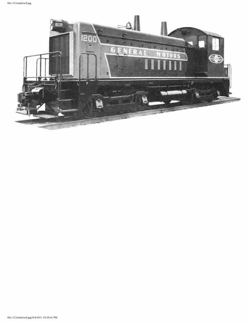
SW9 Locomotive -- 1200 HP
GENERAL DATA
Model SW8 SW9 TR5 TR6
Type 0440 0440 0440-0440 0440-0440
H6rsepower 800 1200 2400 1600
Equipment 8-567B engine 1 ----- ----- 2 12-567B engine ---- 1 2 ---- Model D15C main generator 1 1 2 2 Model D27 traction motors 4 4 8 8
Weight - fully loaded (approx.) 230,000 lbs. 248,000 lbs. 496,000 lbs. 460,000 lbs.
Weight on drivers 100% 100% 100% 100%
Couplers Type "E" Type "E" Type "E" Type "E"
Supplies
Fuel oil 600 U.S. gals. 600 U.S. gals. 1200 U.S. gals. 1200 U.S. gals. 500 Imp. gals. 500 Imp. gals. 1000 Imp - gals. 1000 Imp. gals
130 U.S. gals. 165 U.S. gals. 330 U.S. gals. 260 U.S. gals. Lube oil 108 Imp. gals. 137 Imp. gals. 275 Imp. gals. 216 Imp. gals.
Cooling water capacity 190 U.S.gals. 223 U.S.gals. 446 U.S.gals. 380 U.S.gals ("G" valve level) 158 Imp.gals. 186 Imp.gals. 372 Imp.gals. 316 Imp.gal Sand 28 cu. ft. 28 cu. ft. 56 cu. ft. 56 cu. ft.
file:///C|/emd/sw8-op.html (2 of 7)10/4/2011 10:27:34 PM

EMD SW8 - Operation Manual
General Dimensions Track gauge 4' 8-1/2" 4' 8-1/2" 4' 8-1/2" 4' 8-1/2" Length over coupler pulling faces 44' 5" 44' 511 86' 5" 86' 5" Width over hand holds 10' 2" 10' 2" 10' 2" 10' 2" Maximum height above rail 14' 6-1/4" 14' 6-1/4" 14' 6-1/4" 14' 6-1/4" Truck centers 22' O" 22' 0" 22' O" 22' O" Truck wheelbase 8' O" 8' 0" 8' 0" 8' 0" Wheel diameter 40" 40" 40" 40" Minimum curve radius 100' 0" 100' 0" 100' 0" 100' 0" Gear Ratio 62/15-65/12 62/15-65/12 62/15-65/12 62/15-65/12 Maximum Permissible Speed 65-55 MPH 65-55 MPH 65-55 MPH 65-55 MPH Starting T.E. at 20% Adhesion 46,000 lbs. 49,600 lbs. 99,200 lbs. 92,000 lbs. Starting T.B. at 25% Adhesion 57,500 lbs. 62, 000 lbs. 124,000 lbs. 115,000 lbs. Starting T.B. at 30% Adhesion 69,000 lbs. 74,500 lbs. 149,000 lbs. 138,000 lbs.
TABLE OF CONTENTS
>
SECTION 1 - GENERAL DESCRIPTION 100
- Diesel Engines 100
- Main Generator 101
- Traction Motors 101
- Auxiliary Equipment 102
- Engineman's Controls 103
- - Throttle Lever 103
- - Reverse Lever 105
- - Mechanical Interlocks On the Controller 105
- Engineman's Instrument Panels 105
- - Wheel Slip Indicator 107
- - Lubricating Oil Pressure Gauge 107
- - Engine Temperature Gauge 107
file:///C|/emd/sw8-op.html (3 of 7)10/4/2011 10:27:34 PM

EMD SW8 - Operation Manual
- - Fuel Oil Pressure Gauge 107
- Switcher 107
- - Transition Forestalling Switch 108
- - Road Service Switch 108
- - Control Push-Button Switch Box 109
- - Light Push-Button Switch Box 109
- - Headlight Bright and Medium Switch 109
- - Motor Cut-out Switch 109
- - Isolation Switch 109
- Air Braake Equipment 110
- Miscellaneous Equipment 110
- - Sanding Valve 110
- - Locomotive Bell 110
- - Horn Valve 111
- - Windshield Wiper Valve 111
- - Fire Extinguishers 111
- Engine Room 111
- - Air Box Drains 112
- - Governor, Governor Speed And Safety Control 112
- - Layshaft Manual Control Lever 113
- - Engine Overspeed Trip 113
- - Load Regulator 113
- - Electrical Control Cabinet 114
- - Storage Battery 114
SECTION 2 OPERATION 200
- Before Boarding Locomotive 200
- Precautions Before Starting Engine 200
- To Start Engine 202
- To Stop Engine 202
- Precautions Before Moving Locomotive 203
- To Move Locomotive 203
- Maneuvering 203
- - Throttle Handling 203
- - Reverse Lever 204
- - Transition 204
- - Sanding Valve 206
- - Wheel Slip Indicator 206
file:///C|/emd/sw8-op.html (4 of 7)10/4/2011 10:27:34 PM

EMD SW8 - Operation Manual
- - Braking 206
- Special Operating Conditions 206
- - Freezing Weather Precautions 206
- - Towing Locomotive 207
- - Isolating One Power Truck 208
- - Running Through Water 208
- - Multiple Unit Operation 209
- - Changing Operating Ends 210
SECTION 3 ELECTRICAL EQUIPMENT 300
- General 300
- General Electrical Scheme 300
- Main Generator 301
- Traction Motors 301
- Reversing Locomotive 302
- Electrical Cabinet 302
- 302
- Wheel Slip Control 304
- Ground Relay 305
- Current Limit Relay 305
- Low Voltage, Regulator 305
- Reverse Current Relay 305
- Battery Charging Contactor 306
- Battery Charging Fuse 306
- Auxiliary Generator Field Fuse 306
- Battery Ammeter 306
SECTION 4 - COOLING, LUBRICATING OIL AND FUEL OIL SYSTEMS
400
- Cooling System 400
- Lubricating Oil System 402
- - General 402
- - Oil Level 402
- - Adding Oil To System 402
- - Oil Pressure 402
- Fuel Oil System 403
- - General 403
- - Filling Fuel Tank 405
- - Emergency Fuel Cutoff Valve 405
file:///C|/emd/sw8-op.html (5 of 7)10/4/2011 10:27:34 PM

EMD SW8 - Operation Manual
SECTION 5 - AIR SYSTEM 500
- General 500
- Air Compressor 500
- Draining Of Air System 501
SECTION 6 TROUBLE SHOOTING 600
- General 600
- Trouble Shooting Chart 601
- Engine Does Not Rotate 602
- Engine Rotates But Does Not Fire 603
- Locomotive Does Not Move When Throttle Is Opened 603
- Engine Stops 604
- Battery Ammeter Shows Continual Discharge 604
- Ground Relay 605
- Starting Contactors 605
- Engine Overspeed Trip 605
- Lube Oil Button On The Governor 606
- Emergency Fuel Cutoff Valve 606
SECTION 7 - TRANSFER LOCOMOTIVE OPERATION 700
- Description 700
- Reverse Lever 702
- Mechanical Interlocks On The Controller 702
- Electro-Hydraultc Governor Control 704
- Engine Speed Chart 704
- ER Relay 704
- Isolation Switch 705
- Engine Control Panel C'B " Unit) 706
- Battery 707
- Low Oil Pressure And Lube Oil Suction Alarm 707
- Hot Engine Alarm 707
- Auxiliary Generator Signal Light 707
- Motor Cutout Switch 707
- Air Compressor Control 709
- Dual Cab Control Operation 709
CHARTS
- Electrical Symbols CHART 1
file:///C|/emd/sw8-op.html (6 of 7)10/4/2011 10:27:34 PM

EMD SW8 - Operation Manual
- Schematic Wiring Diagram - 800 HP CHART 2
- Schematic Wiring Diagram - 1200 HP CHART 3
- SW-8 Switcher Outline CHART 4
- SW-8 Switcher Outline CHART 5
file:///C|/emd/sw8-op.html (7 of 7)10/4/2011 10:27:34 PM
file:///C|/emd/sw8-cov.jpg
file:///C|/emd/sw8-cov.jpg10/4/2011 10:29:24 PM
file:///C|/emd/sw9.jpg
file:///C|/emd/sw9.jpg10/4/2011 10:29:41 PM

General Description
SECTION 1
GENERAL DESCRIPTION
The General Motors switching and transfer locomotive models described in this manual are as follows:
● 1. Model SW8 - 800 HP Switching locomotive. ● 2. Model SW9 - 1200 HP Switching locomotive. ● 3. Model TR6 - 1600 HP Transfer locomotive. ● 4. Model TR5 - 2400 HP Transfer locomotive.
The switching-locomotives are customarily single units rated at 800 or 1200 HP, depending on the model. These switchers may be equipped for multiple unit operation.
A transfer locomotive consists of an "A" and "B" unit permanently coupled together. Only one cab is included on such locomotives, and that is on the "A" unit.
100 Diesel Engines The main generator and auxiliaries of these locomotives are driven by a V -type, 2 cycle, Model 567B diesel engine. The cylinders have an 8-1/2" bore and a 10" stroke. The two banks of the engine are arranged with respect to each other at an angle of 45 deg. Figure 1-4 shows the cylinder arrangement of the 8 cylinder 800 HP and 12 cylinder 1200 HP engines.
The SW8 is equipped with an 4-567B engine while the TR6 is provided with the same engine in each of its two units. The. SW9 is powered by a 12-567B engine while the TR5 is supplied with two such engines.
The engine is started by temporarily using the main generator as a starting motor. Current from a storage battery "motors" the main generator to rotate the diesel engine.
The 8-567B engine is equipped with a single scavenging air blower while the 12-567B has two such blowers. Each blower is equipped with an air filter, the elements of which are 4" thick.
101 Main Generator The main generator Model D15C is directly coupled to the engine through a flexible coupling, and furnishes direct current at a nominal 600 volts to the traction motors. This generator is a constant KW generator which at full throttle delivers 560 KW to the traction motors on the SW8 or 848 KW to the traction motors on the SW9.
102 Traction Motors Four Model D27 traction motors are used in each unit, mounted one on each axle. Each motor is geared to the axle which it drives by a motor pinion gear meshing with an axle gear. The gear ratio between the two gears is expressed as a double number such as 62/15. In this case the axle gear has 62 teeth while the pinion gear has 15 teeth.
file:///C|/emd/sw8-sec1.html (1 of 13)10/4/2011 10:29:53 PM
General Description
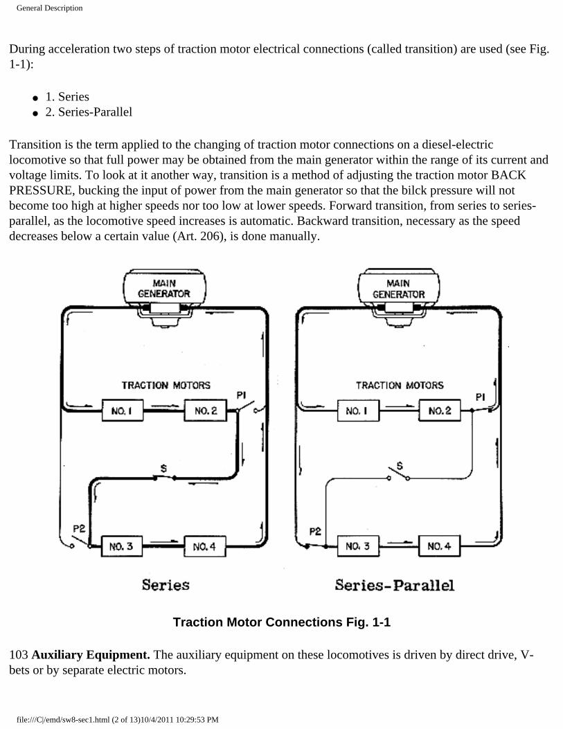
During acceleration two steps of traction motor electrical connections (called transition) are used (see Fig. 1-1):
● 1. Series ● 2. Series-Parallel
Transition is the term applied to the changing of traction motor connections on a diesel-electric locomotive so that full power may be obtained from the main generator within the range of its current and voltage limits. To look at it another way, transition is a method of adjusting the traction motor BACK PRESSURE, bucking the input of power from the main generator so that the bilck pressure will not become too high at higher speeds nor too low at lower speeds. Forward transition, from series to series-parallel, as the locomotive speed increases is automatic. Backward transition, necessary as the speed decreases below a certain value (Art. 206), is done manually.
Traction Motor Connections Fig. 1-1
103 Auxiliary Equipment. The auxiliary equipment on these locomotives is driven by direct drive, V-bets or by separate electric motors.
file:///C|/emd/sw8-sec1.html (2 of 13)10/4/2011 10:29:53 PM
General Description
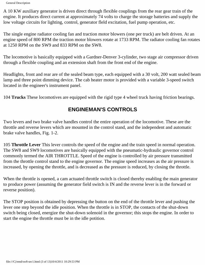
A 10 KW auxiliary generator is driven direct through flexible couplings from the rear gear train of the engine. It produces direct current at approximately 74 volts to charge the storage batteries and supply the low voltage circuits for lighting, control, generator fleld excitation, fuel pump operation, etc.
The single engine radiator cooling fan and traction motor blowers (one per truck) are belt driven. At an engine speed of 800 RPM the traction motor blowers rotate at 1733 RPM. The radiator cooling fan rotates at 1250 RPM on the SW9 and 833 RPM on the SW8.
The locomotive is basically equipped with a Gardner-Denver 3-cylinder, two stage air compressor driven through a flexible coupling and an extension shaft from the front end of the engine.
Headlights, front and rear are of the sealed beam type, each equipped with a 30 volt, 200 watt sealed beam lamp and three point dimming device. The cab heater motor is provided with a variable 3-speed switch located in the engineer's instrument panel.
104 Trucks These locomotives are equipped with the rigid type 4 wheel truck having friction bearings.
ENGINEMAN'S CONTROLS
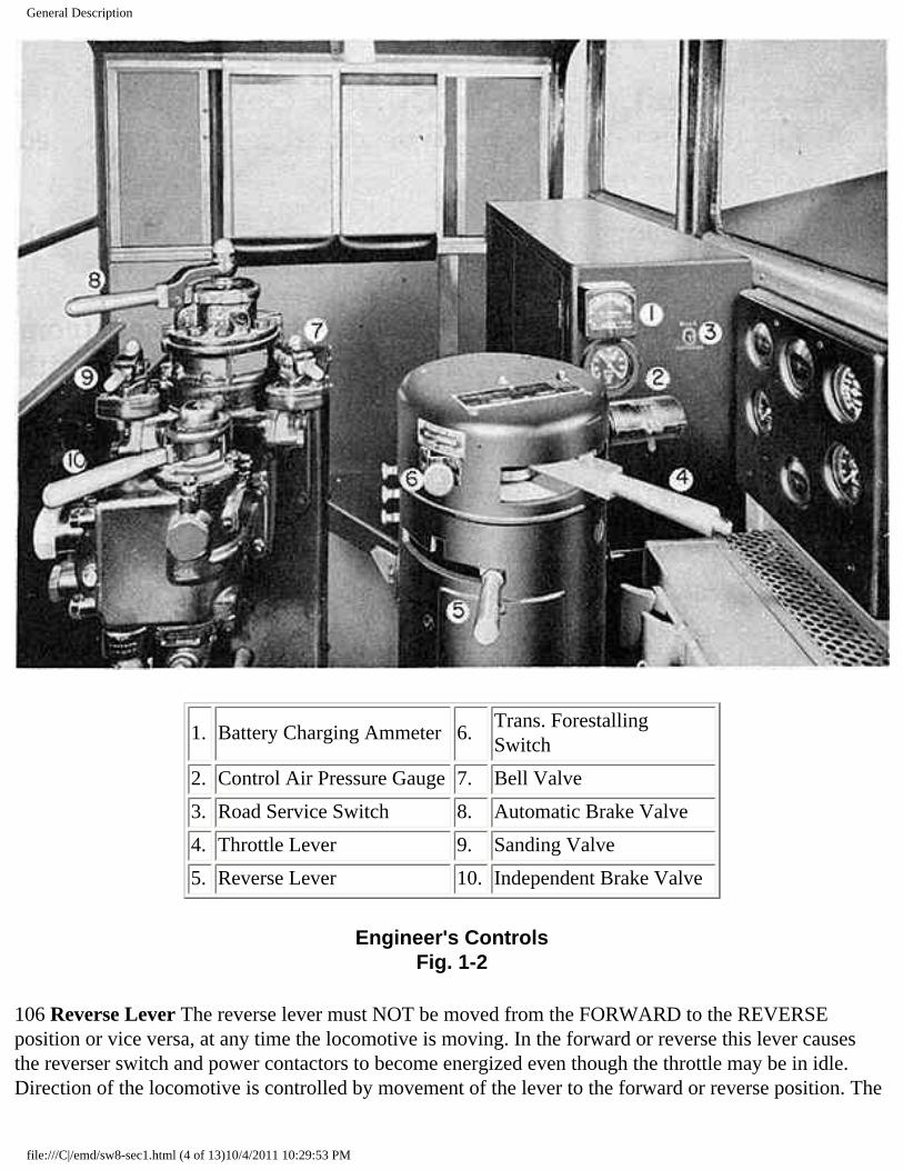
Two levers and two brake valve handles control the entire operation of the locomotive. These are the throttle and reverse levers which are mounted in the control stand, and the independent and automatic brake valve handles, Fig. 1-2.
105 Throttle Lever This lever controls the speed of the engine and the train speed in normal operation. The SW8 and SW9 locomotives are basically equipped with the pneumatic-hydraulic governor control commonly termed the AIR THROTTLE. Speed of the engine is controlled by air pressure transmitted from the throttle control stand to the engine governor. The engine speed increases as the air pressure is increased, by opening the throttle, and is decreased as the pressure is reduced, by closing the throttle.
When the throttle is opened, a cam actuated throttle switch is closed thereby enabling the main generator to produce power (assuming the generator field switch is IN and the reverse lever is in the forward or reverse position).
The STOP position is obtained by depressing the button on the end of the throttle lever and pushing the lever one step beyond the idle position. When the throttle is in STOP, the contacts of the shut-down switch being closed, energize the shut-down solenoid in the governor; this stops the engine. In order to start the engine the throttle must be in the idle potition.
file:///C|/emd/sw8-sec1.html (3 of 13)10/4/2011 10:29:53 PM
General Description
1. Battery Charging Ammeter 6.Trans. Forestalling Switch
2. Control Air Pressure Gauge 7. Bell Valve
3. Road Service Switch 8. Automatic Brake Valve
4. Throttle Lever 9. Sanding Valve
5. Reverse Lever 10. Independent Brake Valve
Engineer's Controls Fig. 1-2
106 Reverse Lever The reverse lever must NOT be moved from the FORWARD to the REVERSE position or vice versa, at any time the locomotive is moving. In the forward or reverse this lever causes the reverser switch and power contactors to become energized even though the throttle may be in idle. Direction of the locomotive is controlled by movement of the lever to the forward or reverse position. The
file:///C|/emd/sw8-sec1.html (4 of 13)10/4/2011 10:29:53 PM
General Description
reverse lever cannot be moved unless the throttle is in idle. In neutral the power contactors will not close when the throttle is opened. With the throttle in idle, the reverse lever can be removed from the control stand when the lever is in the neutual position. The operating controls are locked by removal of the reverse lever from the control stand.
107 Mechanical Interlocks On the Controller The levert on the control stand are interlocked so that:
● 1. The reverse levr can be operated only with the throttle in idle. ● 2. The reverse lever can only be removed from the controller when in neutral position with the
throttle in idle. ● 3. The throttle can be moved to stop with any position of the reverse lever. ● 4. The transition forestallig switch may only be moved with the throttle 1" or more below the full
throttle position. ● 5. The reverse lever must be in neutral in order to start the engine.
ENGINEMAN'S INSTRUMENT PANEL
The instrument panel contains gauges and light indicators to guide the engineman in the proper operation of the locomotive, Fig. 1-3.
file:///C|/emd/sw8-sec1.html (5 of 13)10/4/2011 10:29:53 PM

General Description
Engineer's Instrument Panel -- 800 and 1200 HP Fig. 1-3
108 Air Gauges The air gauges show the main reservoir, equalizing reservoir, brake cylinder and brake pipe pressures.
file:///C|/emd/sw8-sec1.html (6 of 13)10/4/2011 10:29:53 PM

General Description
109 Wheel Slip Indicator The flashing of this light indicates that a pair or more, of the locomotives wheels are slipping.
On the SW9 (1200 HP), and TR5 (2400 HP) locomottves the continuous burning of this light indicates an overloading of the main generator. When this happens the engineman must manually cause backward transition to be made.
110 Lubricating Oil Pressure Gauge This gauge indicates the pressure of the lubricating oil at the rear of the engine. With hot oil the reading should be 20 pounds or more at 800 RPM.
111 Engine Temperature Gauge This gauge shows the temperature of the engine cooling water leaving the engine. Automatically controlled shutters will normally keep the cooling water temperature between 150 and 180 degrees.
112 Fuel Oil Pressure Gauge The pressure of the fuel in the return line from the engine to the main fuel tank is shown by this gauge. The pressure should be approximately 5 pounds.
SWITCHES
The electrical control cabinet contains the main battery, control and light switches as well as their respective fuses. These switches are clearly labeled as to their purpose and are closed during normal operation. The more frequently used control switches are mounted within reach of the engineman at his control station.
113 Transition Forestalling Switch The transition forestalliig switch is a push-pull switch mounted on the control stand above the reverse lever and to, the left of the throttle. The function of this switch is to forestall an undesired forward transition such as when kicking cars on a lead. If this switch is pushed in (IN-SERIES), forward transition will not take place, regardless of locomotive speed or main generator voltage; the motor connections will remain in series. If the switch is pulled out (OUT-AUTO), forward transition will take place when the main generator voltage reaches the pick-up value of the forward transition relay "FTR." The motor connections will then change to series-parallel.
When in full throttle, backward transition from series-parallel to series is made by either closing the throttle to idle and then opening it again, or by reducing the throttle 1" or more and pushing the switch in (IN-SERIES), completing backward transition. The transition forestalling switch is mechanically interlocked with the throttle so that it can not be moved with the throttle wide open; the throttle must be partially closed.
114 Road Service Switch The road service switch is a toggle switch located on the right side of the electrical cabinet. This switch has two positions ROAD and SWITCHING. The switch should be placed in the position corresponding to the type of service being performed.
file:///C|/emd/sw8-sec1.html (7 of 13)10/4/2011 10:29:53 PM

General Description
In the ROAD position modified maximum field starting is provided, while full maximum field starting is obtained when the switch is in the SWITCHING position.
When operating with multiple unit locomotives the function of the road service switch is trainlined, provided that the road service switch in the non-operative cab is left in the SWITCHING position.
115 Control Push-Button Switch Box The engineman's control push-button switch box is located alongside and to the left of the controller. This box contains the control, generator field, fuel pump, engine start and the main cab heater, switches and fuses. The switches are clearly labeled for their respective uses.
116 Light Push-Button Switch Box The light push-button switch box is located on the right cab wall forward of the side window. It contains the headlight, gauge light and cab light switches and fuses.
117 Headlight Bright And Medium Switch The headlight switch above the light push-button switch box, controls the front and rear headlights. The desired dim headlight push-button must first be IN before the headlight switch is operative. The front and rear headlights may be on dim at the same time if both switches are IN at the light pash-button switch box. Only one headlight can be on medium or bright at a time.
118 Motor Cut-Out Switch A motor cut-out switch is mounted on the electrical control panel. This switch permits the isolation of one of the power trucks following a minor failure or emergency in case it is desired to move the locomotive under its own power (see Art. 207-3).
119 Isolation Switch (If Used) An isolation switch is used on transfer locomotives or those equipped for multiple unit operation. This switch is mounted in a metal box near the rear window sill behind the engineman's control station. The switch has two positions START and RUN. In the START position the power plant is isolated from the normal control circuits and the engine speed will remain at, or be reduced to, idle. The reverser and power contactors will not operate. and the engine will not respond to throttle control. The STOP push button on the isolation switch box is effective only when the isolation switch is in the START position, Fig. 7-2.
AIR BRAKE EQUIPMENT
120 General The locomotive is equipped with the latest schedule 6BL (USA) or 6SL (Canadian) air brake equipment.
The equipment and operation of the 6BL or 6SL brake is practically the same as that of the 6ET brake, with the exception of a self-lapptng independent brake valve and a few other modifications.
As all enginemen are more or less familiar with the operation of the 6ET brake, no detailed operation of the 6BL or 6SL will be included.
file:///C|/emd/sw8-sec1.html (8 of 13)10/4/2011 10:29:53 PM

General Description
Special instructions for special applications may be had from the air brake manufacturer upon request by the customer.
MISCELLANEOUS EQUIPMENT
121 Sanding Valve This valve is located on the brake stand just to the left of the automatic brake valve. Moving the double acting sanding valve forward operates the four sand traps in the forward direction. Four sand traps in the reverse direction are similarly operated by moving the sanding valve handle to the rear.
122 Locomotive Bell A 12" locomotive signal bell placed on top 'of the hood just ahead of the first exhaust stack. It is operated by a valve located on the brake stand, just to the right of the automatic brake valve.
123 Horn Valve The horn is operated by an air valve which is controlled by a pull-cord within reach of the engineer. A shut-off cock is included in the air line to the horn and must be open for normal operation. This cock is located just underneath the cab floor in the right front corner and can be reached through the right side access door.
124 Windshield Wiper Valves A needle valve located at each of the wipers controls their speed, also turning them on or off. A master valve located under the engineer's instrument panel controls the main air supply to the wipers.
125 Fire Extinguishers Two (2) one-gallon CTC fire extinguishers are provided on the locomotive, one located in the cab and one in the power plant compartment. Operating instructions are given on the outside of the container and are quite simple. Everyone should feel obliged to familiarize himself with these instructions as prompt action in an emergency may prevent a tragedy.
ENGINE ROOM
file:///C|/emd/sw8-sec1.html (9 of 13)10/4/2011 10:29:53 PM
General Description
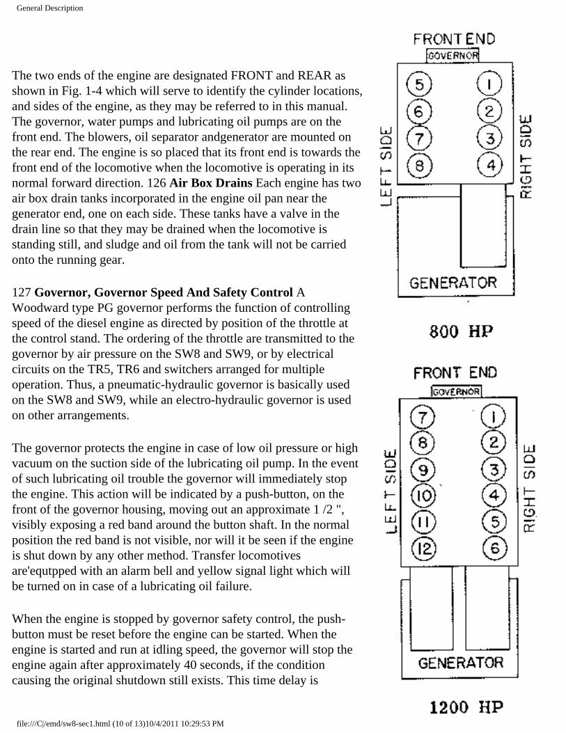
The two ends of the engine are designated FRONT and REAR as shown in Fig. 1-4 which will serve to identify the cylinder locations, and sides of the engine, as they may be referred to in this manual. The governor, water pumps and lubricating oil pumps are on the front end. The blowers, oil separator andgenerator are mounted on the rear end. The engine is so placed that its front end is towards the front end of the locomotive when the locomotive is operating in its normal forward direction. 126 Air Box Drains Each engine has two air box drain tanks incorporated in the engine oil pan near the generator end, one on each side. These tanks have a valve in the drain line so that they may be drained when the locomotive is standing still, and sludge and oil from the tank will not be carried onto the running gear.
127 Governor, Governor Speed And Safety Control A Woodward type PG governor performs the function of controlling speed of the diesel engine as directed by position of the throttle at the control stand. The ordering of the throttle are transmitted to the governor by air pressure on the SW8 and SW9, or by electrical circuits on the TR5, TR6 and switchers arranged for multiple operation. Thus, a pneumatic-hydraulic governor is basically used on the SW8 and SW9, while an electro-hydraulic governor is used on other arrangements.
The governor protects the engine in case of low oil pressure or high vacuum on the suction side of the lubricating oil pump. In the event of such lubricating oil trouble the governor will immediately stop the engine. This action will be indicated by a push-button, on the front of the governor housing, moving out an approximate 1 /2 ", visibly exposing a red band around the button shaft. In the normal position the red band is not visible, nor will it be seen if the engine is shut down by any other method. Transfer locomotives are'equtpped with an alarm bell and yellow signal light which will be turned on in case of a lubricating oil failure.
When the engine is stopped by governor safety control, the push-button must be reset before the engine can be started. When the engine is started and run at idling speed, the governor will stop the engine again after approximately 40 seconds, if the condition causing the original shutdown still exists. This time delay is
file:///C|/emd/sw8-sec1.html (10 of 13)10/4/2011 10:29:53 PM

General Description
provided to allow a check to determine the difficulty. If an attempt is made to run the engine above idling speed during the delay period, the governor will tmmedtiltely stop the engine should the oil pressure be low or the oil pump suction high. Engine Cylinder Arrangement
Fig. 1.4
128 Layshaft Manual Control Lever The layshaft manual control lever is attached to the end of the infector control shaft at the left front corner of the engine. This lever may be used for manually shutting down the engine as well as facilitating the starting of a cold engine.
129 Engine Ovrspeed Trip If the engine speed exceeds approximately 910 RPM an engine overspeed device located in the front end of the engine will trip and bring the engine to a stop. Once this overspeed device is tripped it must be reset manually (by pulling the lever counter-clockwise until it latches) before the engine can again be started, Fig. 6-4.
130 Load Regulator The load regulator is located under the engine hood near the left front corner of the engine. Movement of the load regulator is controlled by engine lubricating oil directed by the load regulator pilot valve and a dump valve (ORS) in the engine governor. The function of the load regulator is to automatically vary the battery field strength in the maingenerator, thereby maintaining power output, corresponding to a definite rate of fuel consumption as determined by the position of the throttle.
The load regulator is in minimum field when the long end of the brush arm is in the 11 o'clock position. Maximum field is obtained with the brush arm in the 2 o'clock position.
file:///C|/emd/sw8-sec1.html (11 of 13)10/4/2011 10:29:53 PM

General Description
Control Regulator Fig. 1-5
131 Electrical Control Cabinet The electrical control cabinet, in the forward end of the cab, contains the high and-low voltage equipment (contactors, relays, fuses, instruments, etc.).
132 Control Air Pressure Regulator The control air for operating power contactors, reverser, and air throttle is supplied from the main reservoir and is reduced to 80 +/- 3 pounds by the control air pressure regulator. This regulator is located in the compartment beneath the cab floor. The control air pressure is indicated on a gauge mounted on the right side of the electrical control cabinet in the cab. Control air pressure is adjusted by turning the knob on top of the regulator.
133 Storage Battery A 32 cell, 64 volt, 284-amipere (8 hour rating) battery is located in the battery box behind the cab. The battery supplies the power start the engine while also providing current to the low voltage system when necessary.
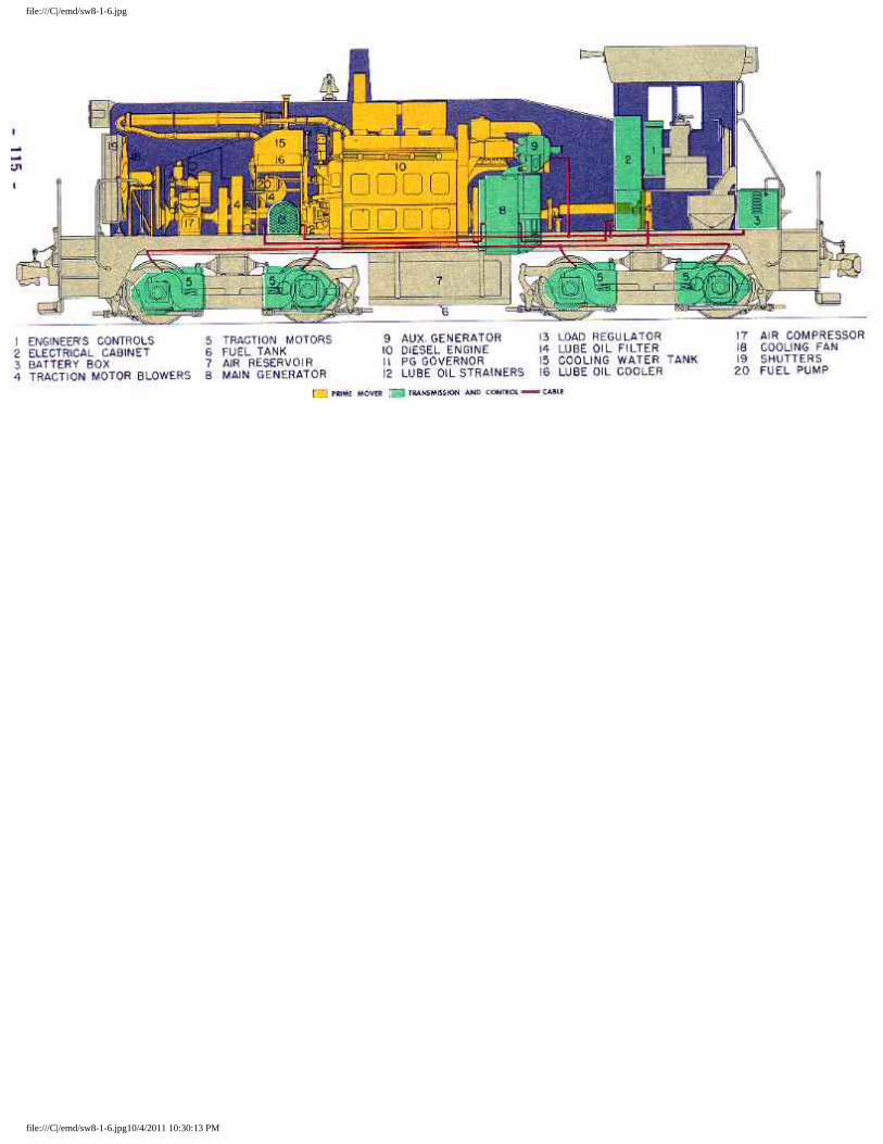
General Arrangement
file:///C|/emd/sw8-sec1.html (12 of 13)10/4/2011 10:29:53 PM

General Description
file:///C|/emd/sw8-sec1.html (13 of 13)10/4/2011 10:29:53 PM
file:///C|/emd/sw8-1-6.jpg
file:///C|/emd/sw8-1-6.jpg10/4/2011 10:30:13 PM

Section 2 - Operations
SECTION 2
OPERATION
The successful and dependable operation of these locomotives is almost entirely dependent upon the quality of inspection and repair at regular maintenance periods, as well as the proficiency of the operating crews. As a supplement to terminal maintenance, a "pre-service check" should be made by the engine crew upon boarding the locomotive.
200 Before Boarding Locomotive-inspect Exterior Of Locomotive And Running Gear For:
● 1. Liquids leaking from the locomotive. ● 2. Loose or dragging parts. ● 3. Proper positioning of angle cocks and shutoff valves. ● 4. Worn or missing brake shoes. ● 5. Flat or shelled out spots on wheels. ● 6. Proper operation of coupler knuckles at both ends of locomotive. ● 7. Observe brake cylinder piston travel, if air brakes are set. ● 8. Check fuel supply in sight glass on fuel tank. ● 9. Drain condensation from main reservoirs.
201 Precautions Before Starting Engine The following operations should be performed when the engine is to be started after a layover. If the engine has been stopped for a short period of time, or if less than the time limit set by the mechanical officials of the individual railroad, Step 5 may be omitted.
● 1. Check position of all valves: a. Drain valves in cooling system, lube oil system, and air reservoirs.
● 2. Check engine cooling water level. ● 3. Check lube oil supply:
❍ a. In engine crankcase. ❍ b. In engine governor. ❍ c. In air compressor.
● 4. At electrical cabinet: ❍ a. Be sure all fuses are in place:
■ 400 ampere - engine starting ■ 150 ampere - battery charging ■ 70 ampere - battery field ■ 60 ampere - battery positive ■ 30 ampere - auxiliary generator field
❍ b. Close main battery switch. ● 5. Test for water accumulation in engine cylinders.
file:///C|/emd/sw8-sec2.html (1 of 8)10/4/2011 10:30:26 PM

Section 2 - Operations
❍ a. Open cylinder test valves (3 full turns) at each cylinder. ❍ b. Place engine throttle in STOP position at engineer's control station. ❍ c. Push control push-bufton switch IN. ❍ d. Place reverse lever in neutral. ❍ e. Press ENGINE START bufton in for sufficient time to rotate engine several
revolutions. ❍ f. If engine has been shut down for a considerable period of time, omit Step 5-e, remove
400-ampere starting fuse and- jack engine over by hand. ❍ g. Watch cylinder test valves while engine is being rotated. If discharge of water appears,
do not attempt to start the engine until cause of water accumulation has been located and corrected.
❍ h. Close cylinder test valves. ❍ i. Replace the 400-ampere starting fuse if Step 5-f was followed.
202 To Start Engine
● 1. Place the reverse lever in the NEUTRAL position. ● 2. Place throttle in IDLE position and place independent brake valve in full application position. ● 3. Push IN the control and fuel pump switches. ● 4. When fuel gauge shows pressure, press engine, START bufton in and hold until engine. fires.
(Not more than 15 seconds). ● 5. For starting troubles see Section 6. ● 6. After the engine is started.
❍ a. Check engine oil pressure. ❍ b. Checkthe starting contactors to make certain they are open. ❍ c. Check ground protective relay to see that it did not trip when the engine was started.
203 To Stop Engine
● 1. Depress bufton on the end of the throttle and close throttle to the STOP position. ● 2. Pull OUT control, fuel pump and generator field switches. ● 3. Remove reverse lever from controller.
204 Precautions Before Moving Locomotive
● 1. NEVER attempt to move locomotive, under its own power, without having first observed proper application and release of locomotive brake shoes.
● 2. Check main reservoir and control air pressure. ● 3. Release hand brake. ● 4. Make sure engine cooling water is 125 degs or more. ● 5. Check lubricating oil pressure.
file:///C|/emd/sw8-sec2.html (2 of 8)10/4/2011 10:30:26 PM

Section 2 - Operations
205 To Move Locomotive
● 1. Put generator field switch IN. ● 2. Place reverse lever in direction locomotive is to be moved. ● 3. Release air brakes. ● 4. Open throttle as required.
206 Maneuvering.
1. Throttle, Handling
It is never necessary to move the throttle hastily, except in an emergency. The throttle should be opened with a steady motion but gradually enough to move the load without slipping the wheels. It is a poor practice and unnecessary to PUMP (rapidly opening and closing) the throttle when starting; a smooth flow of power is more desirable.
If wheel slipping occurs, the engineer should wait until the wheel slip light stops flashing before any sand is used. Sand should be used to PREVENT slipping, NOT to stop it (see Rem 5, Page 206).
When operating over railroad crossings the throttle must be reduced to about one-third of full throttle. This is to prevent arcing of brushes on the traction motor commutators when the wheels are jarred crossing frogs.
2. Reverse Lever The reverse lever is not to be moved at any time that the locomotive is in motion. It is a good practice to remove the reverse lever from the controller, when leaving the locomotive.
3. Transition
● a. These locomotives are equip ped with automatic forward transition from series to series -parallel. Forward transition can be forestalled by placing the transition switch in the IN-SERIES position. Backward transition is NOT automatic but mus be made manually, in the event that the speed of the locomotive decreases to the point where backward transition is necessary. In many instances the engineman will be able to predetermine that forward transition will not be desirable; in this case it will be found advantageous to forestall forward transition by pushing in the transition, or forestalling switch, to the IN-SERIES position. Generally speaking, pulling out the transition switch to the OUT-AUTO position, thereby allowing the locomotive to make forward transition, will be found more useful in effecting fast transfer service, than in general yard switching.
If forward transition has taken place and shortly thereafter manual backward transition becomes necessary, it may be done by either of the two following methods:
file:///C|/emd/sw8-sec2.html (3 of 8)10/4/2011 10:30:26 PM

Section 2 - Operations
❍ (1) Momentarily reduce the throttle from the full throttle position approximately 1" and push the transition switch into the IN-SERIES position.
❍ (2) Momentarily reduce the throttle to idle. ● b. Transition Speeds
The forward transition speeds are tabulated in the table below. These calculated speeds shown will vary'slightly in actual service depending on horsepower output, wheel wear, the setting of the forward transition relay and the current limit relay (if used).
The locomotive is not equipped with automatic backward transition. The backward transition speeds are for reference purposes only and are intended to serve as an indicator to the engineman when backward transition must be made.
Model Gear RatioMax. Top Speed
Forward Transition Speed
Backward Transition Speed
SW8 & TR6
65/12 55 MPH 7.1 MPH 4.5 MPH
SW8 & TR6
62/15 65 " 9.4 " 6.1 "
SW9 & TR5
65/12 55 " 6.0 " 7.5 "
SW9 & TR5
62/15 65 " 7.5 " 9.5 "
NOTE: The maximum top speed shown refers only to the safe rotational speed of the D27 tractionmotor armature. The actual safe top speed limit should be based on the individual roadbed, weight of rail, and/or other railroad considerations.
● 4. Sanding Valve
The double acting sanding valve is located on the left side of the brake stand. Moving the valve handle forward operates the four sand traps for forward movement; moving the handle to the rear operates the four sand traps for reverse movement.
● 5. Wheel Slip Indicator
If wheel slipping occurs, the wheel slip relay (WSR) in the electrical control cabinet will pick up. This will light the wheel slip indicator on the engineer's imtrument panel in the cab. Wheel slip relay action automatically reduces the power output of the main generator which thereby reduces the traction motor torque, stopping the slipping.
file:///C|/emd/sw8-sec2.html (4 of 8)10/4/2011 10:30:26 PM

Section 2 - Operations
It will often be unnecessary to reduce the throttle because of momentary wheel slip action, as the locomotive will automatically reduce its power to stop the slipping and reapply the power after the slipping has stopped. However, under extreme rail conditions, repeated and consecutive slipping may occur. In this case the throttle should be reduced immediately to a throttle position which will apply the maximum power permissible without causing excessive slipping. Sand should be used to prevent slipping, not to stop it.
● 6. Braking
The method of handling the air brake equipment is left to the discretion of the individual railroad. However, the throttle MUST be in idle before the locomotive comes to a dead stop.
207 Special Operating Conditions
1. Freezing Weather Precautions
If the locomotive is to be left standing out in freezing weather, with the engine shut down, steam should be applied to prevent the engine cooling system from freezing, or, if steam is not available, the system must be drained.
A steam connection is provided on the left side of the locomotive, to the rear of the water filler pipe, and underneath the locomotive frame. When steam is applied to the system, the "G" valve should be opened so that condensate from the steam will not'raise the water level and fill the radiators. A steam admission valve (globe valve) and a check valve are located just above the engine room floor, at the front of the engine, the left side of the locomotive. The steam pressure on should not exceed 50 pounds. When disconnecting the steam line, close the steam admission valve (globe valve) to prevent loss of engine cooling water in case the check valve does not seat properly.
If the cooling system is to be drained, the entire cooling system will drain through the drain valve, with the exception of the right water pump. Open the drain in the bottom of the right water pump housing to prevent its freezing. (Leave the cab heater valve open).
2. Towing Locomotive
a. Remove reverse lever from control stand.
b. If the locomotive is to be towed in a train any appreciable distance, the reverser must be placed and locked in the neutral, or center position. With control air available, the reverser may be centered by lightly punching the button on top of the forward or reverse magnet valve. If control air is not available the reverser must be centered manually. This may be done by placing a small rod through the round hole on the lower end of the reverser shaft and rotating the reverser to the neutral position. To lock the reverser, remove the locking pin normally located in the left hand
file:///C|/emd/sw8-sec2.html (5 of 8)10/4/2011 10:30:26 PM

Section 2 - Operations
side of the reverser housing; insert this pin through the hole in the right side of the reverser housing screwing pin securely into place.
c. The air brake equipment should be set according to the air brake manufacturer's bulletins.
3. Isolating One. Power Truck
A three position snap type motor cutout switch is mounted on the, electrical control panel, Fig. 3-1. For normal operation, the arrow on the switch handle points straight up. To cut out #1 truck, turn the switch right (clockwise) and to the left (counter-clockwise) to cut out #2 truck. This motor cutout switch is to be used only in an emergency, or ff a traction motor should develop a minor failure and the locomotive is to be run to the maintenance shop. Do not attempt to move cars with one truck cut out, as serious damage to the electrical equipment may result. Do not operate at more than one half throttle, with one truck isolated.
CAUTION: Isolation of one truck ELIMINATES wheel slip protection on the locomotive or unit affected. The wheel slip indicator will be lit continuously during such operation.
4. Running Through Water
Under absolutely no circumstances should the locomotive pass through water which is deep enough to touch the bottom of the traction motor frames. When passing through water, always go at a very slow speed (2 to 3 mph). Water any deeper than 3 inches above the top of the rail is likely to cause damage to the traction motors.
208 Multiple Unit Operation Switching locomotives are basically designed for single unit operation, but can be arranged for multiple unit operation.
A locomotive equipped for "MU" operation is suppliedwith the same electro-hydraulic governor control and controller that is supplied on transfer locomotives. An isolation switch (Art. 119) is also provided.
These locomotives have an alarm system similar to that on road locomotives. This system is equipped with an alarm bell and signal lights providing protection in case of lubricating oil trouble or hot engine water temperature. In case of trouble the alarm bell will ring in all units but the signal light will be lft only in the unit affected.
file:///C|/emd/sw8-sec2.html (6 of 8)10/4/2011 10:30:26 PM

Section 2 - Operations
The mechanical interlocks on the controller are identical to those on transfer locomotives, given in Art. 703.
The instructions for the operation of the remote control headlight switch are given on, the face of the switch.
Multiple unt t switching locomotives are equipped with a transition, or forestalling, relay (TR). The purpose of this relay is to trainline the function of the lever operated transition forestalling switch. This relay enables the engtneman, in the operative cab, to forestall transition in all units by movement of the transition forestalling switch to the SERIES ("Off") position at his control station. Similarly, the placing of this switch in the AUTO (#I) position allows all units to make forward transition. This lever operated switch can be moved only when the throttle is in IDLE.
The function of the Road Service Switch is also trainlined. However, it must be remembered that this switch must be left in the SWITCHING position in all trafling units in order that the road service switch in the operative cab will have control of the units in consist.
In multiple unit operation close the push-button control switches in the'controlling cab ONLY (see instructions for changing. operating ends, Art. 209).
209 Changing Operating Ends If the locomotive is equipped for multiple operation (6BL Brake Equipment) the following procedure should be used in, changing from one cab to another:
● 1. REMOVE REVERSE LEVER. ● 2. Make a full service brake pipe reduction and lap the automatic brake valve. ● 3. Place the double-heading cock in the "Trailing" (4 o'clock) position. ● 4. Move the independent brake valve handle to the "Release" position. ● 5. Leave the automatic brake valve in the "Lap" position. ● 6. Pull OUT ("Off" position) all switches at the engineman's control station. ● 7. Place the road service switch in the SWITCHING position. ● 8. Proceed to the control station to be made operalive. Put IN "On" position) the control, fuel
PUMP and any other switches that may be necessary. ● 9. Place independent brake valve handle in the "Full Application" position and insert the reverse
lever in the controller. ● 10. Open the double heading cock slowly to the "Lead" (6 o'clock) position. ● 11. Place the automatic brake valve handle in the "Running" position. ● 12. Place the road service switch in the desired position. ● 13. When ready to move the locomotive, put IN the generator fteld switch and move the
independent brake valve to the "Release" position.
NOTE: When hauling locomotive "dead," place the independent and automatic brake valve handles in
file:///C|/emd/sw8-sec2.html (7 of 8)10/4/2011 10:30:26 PM

Section 2 - Operations
the RELEASE and RUNNING positions respectively; move the double heading cock to the "dead" (3 o'clock) position and open the dead engine cock.
file:///C|/emd/sw8-sec2.html (8 of 8)10/4/2011 10:30:26 PM

Section 3 - Electrical Equipment
SECTION 3
ELECTRICAL EQUIPMENT
300 General The electrical equipment of a diesel locomotive is generally more complicated and confusing to the engineman than are the mechanical items. Thus, this section is being included to discuss ingeneral, those electrical items that may need more explanation than has been given in Sections 1 and 2. it is hoped that the information in this section, while not being extensive, will enable the engineman to obtain a clearer picture of the operation of the locomotive.
301 General Electrical Scheme In the full throttle position the rated horsepower of the diesel engine is delivered to the direct coupled main generator (Model D15C). At the main generator the mechanical power of the engine is transformed into electrical power. The electrical power is then conducted to the four traction motors (Model D27), two motors being located in each truck.
The electrical system of the locomotive can be thought of as being divided into two separate systems: the high voltage system and the low voltage system.
The high voltage system is entirely and directly concerned with the function" of moving the locomotive. The main components of the high voltage system are the main generator, traction motors, reverser drum, wheel slip relay, forward transition relay, shunt field contactor, ground relay, series and parallel power contactors.
The low voltage system contains control circuits which control the flow of power in the high voltage system, and those auxiliary circuits conducting power fuel pump and the to the locomotive lights, heater fan, main generator battery field. A 64 volt storage battery is included in the low voltage system and it is from this source that power is taken to start the diesel engine. Once the engine is started, the auxiliary generator which is driven by the engine through a flexible coupling, takes over the job of supplying Power to the low voltage system. As in an automobile electrical system, the auxiliary generator charges the battery.
302 Main Generator The main generator (Model is directly coupled to the engine through a flexible coupling, and furnishes direct current at a nominal 600 volts to the traction motors. The main generator voltage varies with the speed of the engine and the condition of operation of the locomotive.
303 Traction Motors The traction motors (Model D27) are direct current, series-wound motors geared to the wheel axles. The motors are reversed by changing the direction of flow of current in the field windings the direction of current flow in the armature always being the same. A reverser drum operated by electro-pneumatic control from the cab reverses the current flow in the traction motor field windings.
file:///C|/emd/sw8-sec3.html (1 of 5)10/4/2011 10:30:46 PM

Section 3 - Electrical Equipment
The traction motors are cooled by blowers, one for each truck. The blowers are belt-driven and turn at approximately twice the speed of the diesel engine.
For low speed and heavy traction, the traction motors are connected in series with the main generator. When connected in series the current passes consecutively through each motor before returning to the main generator. For higher speed operation the traction motors are connected to the main generator in what is called a series-parallel connection. In series-parallel, the current from the main generator divides and follows two paths. Each branch consists of two traction motors I return in series. The current paths.then reunite and to the main generator.
304 Reversing Locomotive Movement of the reverse lever from full forward to full reverse energizes either the forward or reverse magnet valves electric on the reverser switch located in the electrical control cabinet. When either of the magnet valves is energized it allows control air to pass through the valve moving the reverser switch to the desired direction.
305 Electrical Cabinet An electrical cabinet at the forward end of the cab contains the high and low voltage equipment (contactors, relays, fuses and instruments (Fig. 3-1).
306 Wheel Slip Control In the event of a pair of wheels slipping the wheel slip relay initiates the action that:
● 1. Lights the wheel slip light. ● 2. Opens the shunt and battery field circuits. ● 3. Causes the load regulator to move to the minimum field position.
When there is a wheel slip indication, it will probably be only one set of wheels that are slipping, unless the rail conditions are extremely bad. During slipping, the wheel slip relay, which contains two normally open interlocks, will become energized thereby closing the intnterlocks. In closing, one of the interlocks will light the wheel slip indicator light; the second interlock establishes a circuit that by-passes, or short circuits, the operating coil of the shunt field contactor. This opens the shunt field contactor, and,consequently, the battery field contactor. When the battery field contactor opens, its normally closed interlock (AB) closes, energizing the overriding solenoid (ORS) in the governor. When the overriding solenoid is energized it causes the load regulator to move toward the minimum field position.
The power output of the main generator to the traction motors, being almost completely reduced, will result in stopping the slipping. As soon as the slipping stops the wheel slip relay drops out and restores delivery of power to the traction motors. See Arts. 109 and. 206.
file:///C|/emd/sw8-sec3.html (2 of 5)10/4/2011 10:30:46 PM
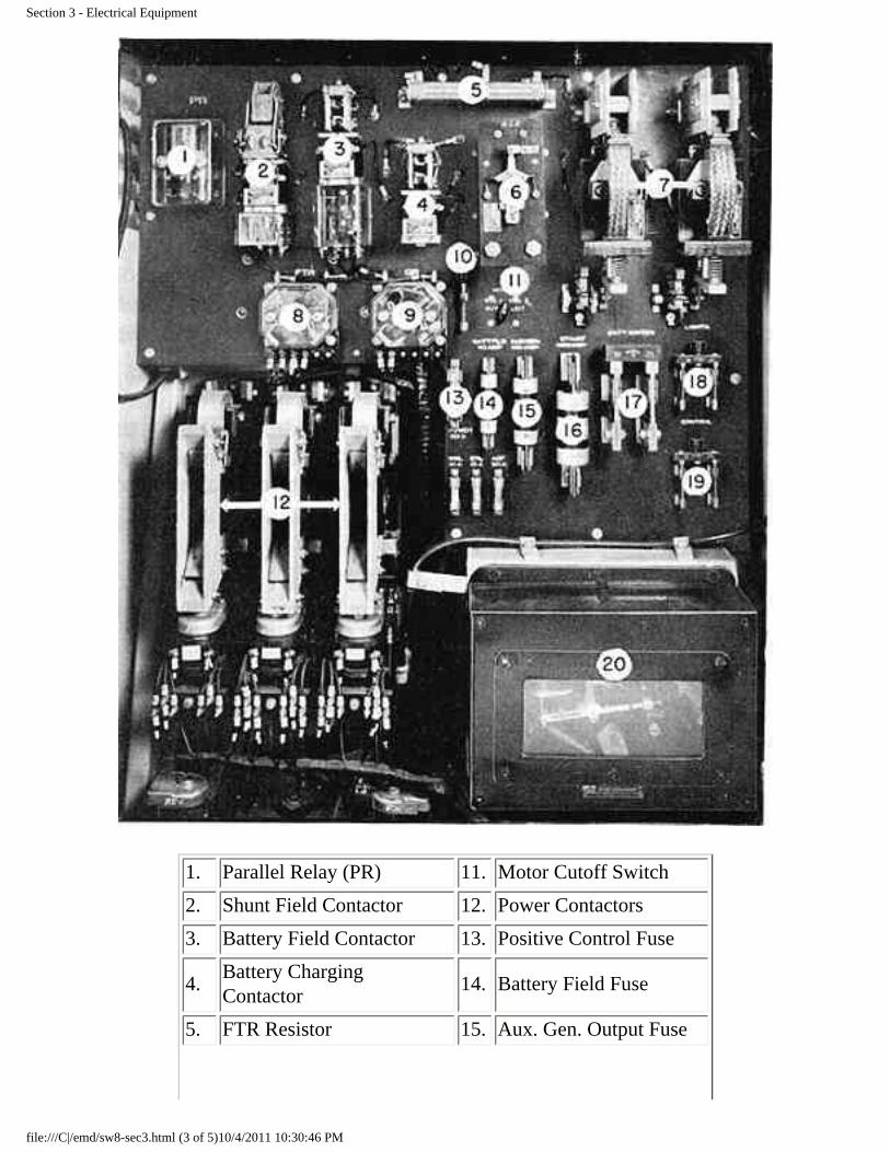
Section 3 - Electrical Equipment
1. Parallel Relay (PR) 11. Motor Cutoff Switch
2. Shunt Field Contactor 12. Power Contactors
3. Battery Field Contactor 13. Positive Control Fuse
4. Battery Charging Contactor
14. Battery Field Fuse
5. FTR Resistor 15. Aux. Gen. Output Fuse
file:///C|/emd/sw8-sec3.html (3 of 5)10/4/2011 10:30:46 PM

Section 3 - Electrical Equipment
6. Reverse Current Relay 16. Starting Fuse (400-Amp)
7. Starting Contactor 17. Main Battery Switch
8. Forward Transition Relay 18. Main Light Switch
9. Ground Relay (GR) 19. Main Control Switch
10. GR Knife Switch 20. Low Voltage Regulator
Electrical Cabinet -- SW8 and SW9 Fig. 3.1
307 Ground Relay (GR) The ground relay, located in the electrical cabinet, is an electrical protective device connected to the high voltage system. The function of this relay is to automatically unload the main generator in case of a ground in the high voltage system (a ground can be defined as current passing through the frame, or carbody, of the locomotive).
If a ground in the high voltage system should occur, the ground relay will trip. When tripped, the ground relay drops out the shunt and battery field contactors, unloading the main generator. The ground relay must be reset before the unit can again deliver power. The relay is reset by pressing in on the reset button on the relay, or on the extension button in the door of the electrical cabinet. Should the relay repeatedly trip when power is applied, the power plant MUST be isolated.
CAUTION: Only reset the ground relay with the engine speed reduced to idle.
If the ground relay trips, the white needle in the relay will point to a red dot. In the normal position the needle points to a yellow dot, Fig. 6-2.
With the ground relay tripped, an air throttle equipped locomotive will allow the engine speed to increase, when the throttle is opened, but no power will be delivered. Under the same circumstances the speed of an engine controlled by an electro-hydraultc governor will be reduced to idle and will remain at that speed unless the throttle is placed in the 5th or 6th position, in which case the engine will stop.
Although a high voltage ground will normally be the only reason for the ground relay tripping, a low gr voltage ground can trip the relay when the engine is started; since at, that time the high and low voltage systems are temporarily connected. Ground relay action is not necessarily an indication of serious trouble but should be reported to the maintenance authorities.
The ground relay knife switch, when open, eliminates the protection of the ground relay. This switch must NOT be opened in normal operation unless definite instructions are issued by an official of the railroad.
file:///C|/emd/sw8-sec3.html (4 of 5)10/4/2011 10:30:46 PM

Section 3 - Electrical Equipment
308 Current Limit Relay (CLR) A current limit relay is supplied on 1200 HP locomotive units. This is a through cable type relay which closes if the current from the main generator becomes excessive. When closed this relay causes the wheel slip indicator light to burn steadily, signaling that backward transition should be made. This relay will not close when in series transition, since wheel slip action will normally take place before the main generator current becomes excessive.
309 Low Voltage Regulator The low voltage regulator regulates the auxiliary generator output voltage, keeping it at an approximate 74 volts, regardless of the speed of the engine..
310 Reverse Current Relay (RCR) This relay, located in the electrical cabinet controls the opening and closing of the battery charging contactor. The reverse current relay causes the battery charging contactor to open when the voltage of the auxiliary generator falls to a point below the battery voltage. This prevents a reverse flow of current from the battery attempting to "motor" the auxiliary generator.
311 Battery Charging Contactor (BC) The battery charging contactor is an electrically operated switch connecting the auxiliary generator to the low voltage system. When the auxuiary generator voltage drops for, any reason (such as stopping the engine), the battery charging contactor opens, due to the operation of the reverse current relay. The battery charging contactor and reverse current relay prevent current from the battery flowing back through the auxiliary generator when the engine is stopped.
312 Battery Charging Fuse (150-amp.) This fuse protects the auxiliary generator against any possible overload. A blown battery charging (auxiliary generator output) fuse will cut off the auxiliary generator from the low voltage system.
313 Auxiliary Generator Field Fuse (30-Amp.) A 30-ampere fuse protects the auxiliary generator field windings against excessive current. Blowing of this fuse will also prevent the auxiliary generator from supplying current to the low voltage system.
314 Battery Ammeter This ammeter is located on the side of the electrical cabinet and shows whether the battery is charging or discharging. The ammeter should show zero or a slight "charge" whenever the engine is running. If the battery ammeter shows a continual discharge an investigation should be made to prevent the battery from eventually running down (Art. 605).
file:///C|/emd/sw8-sec3.html (5 of 5)10/4/2011 10:30:46 PM

Section 4 - Cooling, Lubricating Oil and Fuel Oil Systems
SECTION 4
COOLING, LUBRICATING OIL AND FUEL OIL SYSTEMS
400 Cooling System
1. Water from the cooling water supply tank is pumped through the engine cooling water passages in the engine to the radiators at the top front of the locomotive, whereas it is cooled and returned to the supply tank.
2. A cooling fan located directly behind the shutters at the front of the locomotive, supplies air to the engine radiator. The fan is V-belt driven, through sheaves and jackshafts; speed of the fan is proportional to the speed of the engine.
3. The temperature of the cooling water leaving the engine is shown by a temperature gauge on the instrument panel in front of the engineman.. The temperature of the engine cooling water is controlled byshutters which are automatically operated.
4. The cab heater is connected to the engine cooling system. Hot water from the engine passes through the heater to heat the cab.
5. The engine cooling system is filled either through the filler pipe located on the roof of the locomotive above the water tank, or through the side filler pipe located underneath the locomotive frame, at the left front of the fuel tank. This filler pipe can be identified by a cone shaped fitting on the end of the pipe. When filling the system, the engine should be stopped and the "G" valve, opened. Add water until it runs out the "G" valve drain. Remove filling hose, close "G" valve and start engine.
Lube Oil Schematic Diagram Fig. 4-1
file:///C|/emd/sw8-sec4.html (1 of 5)10/4/2011 10:31:25 PM
Section 4 - Cooling, Lubricating Oil and Fuel Oil Systems
401 Lubricating Oil System
1. General
The savenging oil pump draws oil from the engine oil pan and forces it through the oil cooler and filter to the oil tank strainer chamber. The oil is then drawn through the suction strainers by the lube oil and piston cooling pump, which consists of two pumps in one housing. One section forces oil to the main bearings, gear train, blowers, etc. The second section supplies oil under pressure to cool the pistons. A pressure gauge mounted on the panel in front of the engineman shows the pressure of the lubricating oil.
2. Oil Level
The oil level may be checked with the engine running at any speed, and should read between LOW and FULL on the bayonet gauge in the engine oil pan. When the engine is stopped most of the oil from the filter and oil cooler will drain into the strainer chamber and then overflow into the engine oil pan. The oil level on the bayonet gauge dipstick will then be above the "Running-Full" level.
3. Adding Oil To System
When oil is added to the engine, it must be poured through the opening having the SQUARE cap on top of the strainer housing. Should the round caps be removed while engine is running, hot oil under pressure will come from the openings and possibly cause personal injury.
4. Oil Pressure
a. A lubricating oil pressure gauge, located on the engineman's instrument panel, indicates the pressure of the oil in the rubrical system at the rear of the engine. With hot oil the reading should be 20 pounds or more at 800 RPM.
b. In the event of dangerously low oil pressure, or high oil pump suction, the governor will automatically shut down the engine.
402 Fuel Oil System
1. General
The fuel pump is located at the left hand side of the engine compartment, near the front end of the engine. Fuel is drawn from the storage tank under the locomotive, through the suction side of the dual fuel filter to the motor driven fuel pump. From the pump the fuel is forced consecutively through, the pressure side of the dual fuel filter and the sintered bronze filter. After passing through the sintered bronze filter the fuel flows to the injectors. The excess fuel not used by the injectors returns to the fuel tank through the 5# return fuel sight glass, located on the sintered bronze filter. An orifice restricts the flow of fuel into the glass and maintains a back pressure of fuel on the injectors of approximately 5 pounds. A relief valve is built into the dual filter which by-passes the fuel to the duplex sintered bronze filter on the engine, if the element in the pressure side of the dual filter becomes clogged. The sintered bronze filter is provided with a relief valve and sight glass through which the fuel will by-pass to the fuel tank in case the sintered bronze filter becomes clogged. A pressure gauge is connected to the return flow pipe from the injectors. This gauge is located on the panel in front of the engineman, and indicates whether the engine is getting enough fuel. If the engine is not getting sufficient fuel, this gauge will show little or no pressure at full throttle (the 5# fuel return sight glass will also show this).
file:///C|/emd/sw8-sec4.html (2 of 5)10/4/2011 10:31:25 PM

Section 4 - Cooling, Lubricating Oil and Fuel Oil Systems
Plumbing Stack -- Right Side With 800 HP Engine)
Fig. 4.2
file:///C|/emd/sw8-sec4.html (3 of 5)10/4/2011 10:31:25 PM

Section 4 - Cooling, Lubricating Oil and Fuel Oil Systems
Plumbing Stack -- Left Side With 800 HP Engine)
Fig. 4.3
2. Filling Fuel Tank
The fuel tank may be filled from either side of the locomotive. A direct reading, full length sight level, gauge is located at each side of the fuel tank. This gauge is used while filling the fuel tank to prevent overflowing, and for approximating the amount of fuel remaining in the tank.
3. Emergency Fuel Cutoff Valve (Fig. 4-4)
An emergency fuel cutoff valve is provided in the fuel suction line between the fuel tank and the fuel pump, to cut off the supply of fuel to the pump in case of fire, or an emergency. On each side of the locomotive a small box with a lift cover is attached to the locomotive bed frame. Enclosed in this box is a pull ring on, the end of the cable running to the fuel cutoff valve. A similar ring is attached to the right side of the con- trol stand.
The fuel cutoff valve may be tripped, and the fuel supply cut off from the fuel pump by pulling any one of these rings. If the fuel cutoff valve is tripped, it will have to be reset manually.
To reset: The cutoff valve is located in the fuel suction line just ahead of the fuel tank and immediately below the frame of the locomotive. Reach in and pull the valve stem out enough so the yoke will slide into place, thereby holding the valve open.
file:///C|/emd/sw8-sec4.html (4 of 5)10/4/2011 10:31:25 PM

Section 4 - Cooling, Lubricating Oil and Fuel Oil Systems
emergency Fuel Cutoff Valve Location Fig. 4-4
file:///C|/emd/sw8-sec4.html (5 of 5)10/4/2011 10:31:25 PM
Section 5 - Air System
SECTION 5
AIR SYSTEM
500 General Compressed air is not only used on a diesel-locomotive for operating the air brakes and sanders but is also essential for the proper operation of many other items. The reverser switch, main power contactors, shutter operating cylinder, air throttle, horn, bell and windshield wipers are also air operated. Some of the items mentioned are in reality electro-pneumatically operated. This merely means that in such cases the flow of the air (as through a valve) is controlled by electrical circuits.
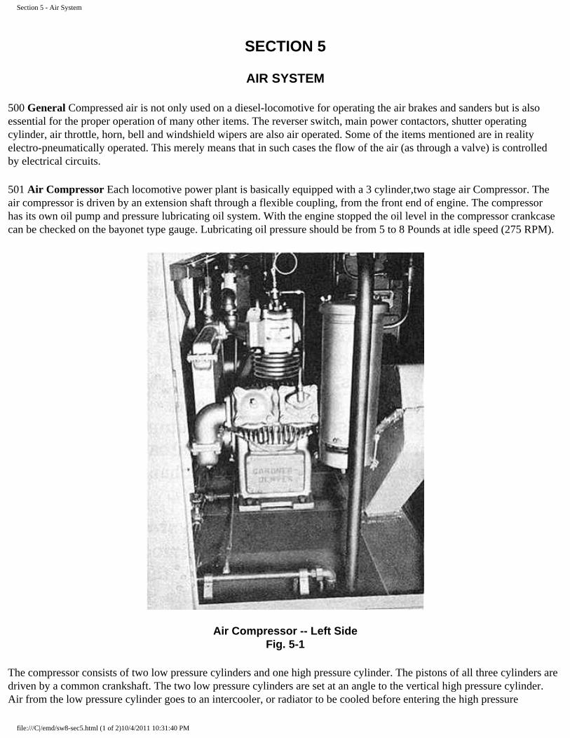
501 Air Compressor Each locomotive power plant is basically equipped with a 3 cylinder,two stage air Compressor. The air compressor is driven by an extension shaft through a flexible coupling, from the front end of engine. The compressor has its own oil pump and pressure lubricating oil system. With the engine stopped the oil level in the compressor crankcase can be checked on the bayonet type gauge. Lubricating oil pressure should be from 5 to 8 Pounds at idle speed (275 RPM).
Air Compressor -- Left Side Fig. 5-1
The compressor consists of two low pressure cylinders and one high pressure cylinder. The pistons of all three cylinders are driven by a common crankshaft. The two low pressure cylinders are set at an angle to the vertical high pressure cylinder. Air from the low pressure cylinder goes to an intercooler, or radiator to be cooled before entering the high pressure
file:///C|/emd/sw8-sec5.html (1 of 2)10/4/2011 10:31:40 PM

Section 5 - Air System
cylinder. The intercooler is provided with a pressure gauge and relief val@e. The gauge normally reads approximately 32 pounds when the compressor is loaded. The intercooler relief valve is set for 50 pounds. Any marked deviation of intercooler pressure from 32 pounds should be reported at the maintenance terminal for attention.
Condensation and oil collects in the sump of the bottom header of the compressor intercooler and should be drained once at each crew change and at the regular maintenance period. A drain valve is provided in each sump for this purpose. Operate the intercooler safety valve by hand, when draining intercooler, to be certain that it functions properly.
Since the air compressor is directly connected to the engine and is in operation at all times when the engine is running, an unloader is provided in the hea of both high and low pressure cylinders which cuts out the compressing action when actuated by air pressure. The unloader accomplishes this by blocking open the suction or intake valves of the high and low pressure cylinders. When the air operating the unloader is cut off, the unloader releases the suction valves and the compressor resumes pumping. Main reservoir air pressure actuates the unloader valves. The air compressor governor is mechanically operated.
502 Draining Of Air System The air system should be drained periodically to prevent moisture from being carried into the air brake and electrical control air systems. The frequency of draining win depend on local conditions and can be determined by practice. It is recommended that draining be done at the time of each crew change, until a definite schedule can be determined by the individual railroad.
Air Schematic Diagram Fig. 5-2
file:///C|/emd/sw8-sec5.html (2 of 2)10/4/2011 10:31:40 PM

Section 6 - Trouble Shooting
SECTION 6
TROUBLE-SHOOTING
600 General It is often stated that on a steam locomotive it takes 5 minutes to find the trouble and an hour to fix it; while on a diesel locomotive it takes an hour to find the trouble but only 5 minutes to correctit. However true the foregoing statement maybe is of no concern, other than to pont out the fact that a logical approach to finding trouble on a diesel, should it happen, is absolutely necessary. By use of this trouble shooting section it is hoped that the afforementioned "hour to find the trouble" will be considerably reduced.
To obtain the full benefit of this section one must THINK and analyze any difficulty encountered before haphazardly pushing buttons, testing fuses, etc. For example, if the locomotive suddenly loses power, a person should stop and think of those fundamental items necessary for the development of power. With a loss of power, the engine will be doing one of two things: RUNNING or STOPPED. If the engine is stopped, obviously, no power can be developed until a check is made of a few items, locating the trouble, and the engine restarted. If the engine is running, then, Of course, items separate from those that would cause the engine to stop must be checked.
As the lack of the usual functioning of but one item will prevent the normal operation of all or a portion of the locomotive, it is strongly suggested that in the event of trouble an attempt be made to first determine, in general, the type of trouble. After making a general diagnosis based on the way the equipment acts, a check should then be made of those items that are known to cause that type of trouble. If it is not known which items to check, following this diagnosis, they will usually be found listed in Articles 601-605.
TROUBLE SHOOTING CHART FOR SW8 AND SW9 LOCOMOTIVES
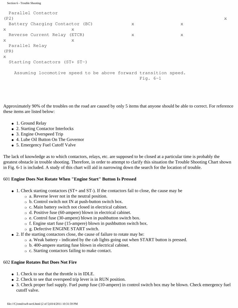
In using this table one must be sure that the control, generator field and fuel pumpswitches are closed ON), and the isolation switch (if used) in RUN. The contactors and relaysfollowed by an "X" are closed, with the throttle and reverse levers in the positions shown.
Throttle Lever Above Or At IDLE IDLE Above IDLE STOP FULL Reverse Lever Neutral Forward Forward Forward Forward Transition Forestalling Switch Series Series Series Series Auto
Reverser Drum (FOR) x x x Reverser Drum (REV) Shunt Field Contactor (SH) x x Battery Field Contactor (BF) x x Series Contactor (S) x x x Parallel Contactor (Pl) x
file:///C|/emd/sw8-sec6.html (1 of 5)10/4/2011 10:31:59 PM
Section 6 - Trouble Shooting
Parallel Contactor (P2) x Battery Charging Contactor (BC) x x x x Reverse Current Relay (ETCR) x x x x Parallel Relay (PR) x Starting Contactors (ST+ ST-)
Assuming locomotive speed to be above forward transition speed. Fig. 6-1
Approximately 90% of the troubles on the road are caused by only 5 items that anyone should be able to correct. For reference these items are listed below:
● 1. Ground Relay ● 2. Starting Contactor Interlocks ● 3. Engine Overspeed Trip ● 4. Lube Oil Button On The Governor ● 5. Emergency Fuel Cutoff Valve
The lack of knowledge as to which contactors, relays, etc. are supposed to be closed at a particular time is probably the greatest obstacle in trouble shooting. Therefore, in order to attempt to clarify this situation the Trouble Shooting Chart shown in Fig. 6-1 is included. A study of this chart will aid in narrowing down the search for the location of trouble.
601 Engine Does Not Rotate When "Engine Start" Button Is Pressed
● 1. Check starting contactors (ST+ and ST-). If the contactors fail to close, the cause may be ❍ a. Reverse lever not in the neutral position. ❍ b. Control switch not IN at push-button switch box. ❍ c. Main battery switch not closed in electrical cabinet. ❍ d. Positive fuse (60-ampere) blown in electrical cabinet. ❍ e. Control fuse (30-ampere) blown in pushbutton switch box. ❍ f. Engine start fuse (15-ampere) blown in pushbutton switch box. ❍ g. Defective ENGINE START switch.
● 2. If the starting contactors close, the cause of failure to rotate may be: ❍ a. Weak battery - indicated by the cab lights going out when START button is pressed. ❍ b. 400-ampere starting fuse blown in electrical cabinet. ❍ c. Starting contactors failing to make contact.
602 Engine Rotates But Does Not Fire
● 1. Check to see that the throttle is in IDLE. ● 2. Check to see that overspeed trip lever is in RUN position. ● 3. Check proper fuel supply. Fuel pump fuse (10-ampere) in control switch box may be blown. Check emergency fuel
cutoff valve.
file:///C|/emd/sw8-sec6.html (2 of 5)10/4/2011 10:31:59 PM

Section 6 - Trouble Shooting
● 4. Layshaft may be stuck in shutdown position. ● 5. Check oil level in governor.
603 Locomotive Does Not Move When Throttle Is Opened
● 1. If the engine does not speed up when the throttle is opened, the cause may be: ❍ a. No control air pressure. ❍ b. Defective governor.
● 2. If the engine.speeds up but locomotive does not move, when the throttle is opened, the cause may be: ❍ a. Reverse lever in neutral position. ❍ b. Generator field switch not IN, or its 15 ampere fuse blown in push-button switch box. ❍ c. Control switch not IN, or its 30-ampere fuse blown in push-button switch box. ❍ d. Starting contactor interlocks not making good contact. e. Control air pressure low. ❍ f. Battery field fuse (70-ampere) blown in electrical cabinet. ❍ g. Reverser interlocks not making good contact. ❍ h. Ground relay tripped (close throttle to idle before resetting). ❍ i. Hand or air brake applied. ❍ j. Throttle switch not making good contact.
604 Engine Stops If the engine stops after previously being in operation, the cause may be:
● 1. Throttle may have been placed in the STOP position. ● 2. Low oil pressure button on the governor might have tripped. ● 3. Engine overspeed lever may be tripped. ● 4. Fuel supply may have stopped because of:
❍ a. Fuel tank empty. ❍ b. Fuel pump fuse blown or switch OUT. ❍ c. Emergency fuel cutoff tripped.
605 Battery Ammeter Shows Continual Discharge
● 1. The battery charging (auxiliary generator output) fuse (150-ampere) may be blown. ● 2. The battery charging contactor may not be closing completely. ● 3. The auxiliary generator field fuse (30-ampere) may be blown in electrical cabinet.
606 Ground Relay If the ground relay is tripped the locomotive will not be able to develop power. Therelay is reset by pressing in on the push-button when the engine is at idle speed.
607 Starting Contactors Starting contactors sometimes weld together when an engine is started, especially if the START button is not held in firmly. If one welds, the locomotive will not move even though the engine will speed up. The contacts may be separated by prying the contacts apart with a piece of wood or other non-conductive material. When the contacts are open the interlocks are closed, and vice versa.
608 Engine Overspeed Trip If the engine speed should exceed approximately 910 RPM an overspeed device will TRIP land stop the engine by preventing the injectors from injecting fuel into cylinders. The overspeed trip must be latched in the SET position before engine can be started.
609 Lube Oil Button On The Governor In case of low oil pressure or high suction the governor will shut the engine down. A push-button on the front of the governor will move out an approximate 1/2", exposing a red band on the button. The engine cannot be restarted until the button has been re- set by being pushed back into the governor housing.
file:///C|/emd/sw8-sec6.html (3 of 5)10/4/2011 10:31:59 PM

Section 6 - Trouble Shooting
610 Emergency Fuel Cutoff Valve If this valve has been tripped, either accidentally or by pulling one of the emergency pull cords the supply of fuel to the engine will be stopped. The valve is located in the fuel suction line just ahead of the right side of the fuel and immediately below the frame of the locomotive. To reset: Reach in and pull valve stem out enough so the yoke will slide into place, thereby holding valve open, Fig. 4-4.
Ground Relay (Set Position) Fig. 6-2
Starting Contactors Fig. 6-3
file:///C|/emd/sw8-sec6.html (4 of 5)10/4/2011 10:31:59 PM

Section 6 - Trouble Shooting
Overspeed Trip Fig. 6-4
PG Governor Fig.6-5
file:///C|/emd/sw8-sec6.html (5 of 5)10/4/2011 10:31:59 PM

Section 7 - Transfer Locomotives
SECTION 7
TRANSFER LOCOMOTIVE OPERATION
700 Description The transfer locomotive Models TR5 and TR6 are rated at 2400 and 1600 horsepower, respectively. These locomotives are composed of an "A" and "B" unit permanently coupled together. Only one operating cab is included on such locomotives, and that is on the "A" unit. The operating control station in the "A" unit is conveniently Located in the operator's cab. An electro-hydraulic governor control system is used, allowing simultaneous control of both power plants from a single operator's control station in the cab.
Each unit being provided with a local control station permits isolation of either power plant without affecting the operation of the other power plant. There is a local control station conveniently located in the operator's cab of the leading unit and at the front end of the trailing unit where it is visible to the engineman.
Each control station is equipped with an isolation switch, fuel and lubricating oil gauges, and signal lights. An alarm bell and a yellow "bull's-eye" signal light is supplied in the cab, and a similar light is located in the panel of the booster unit. This provides for a simultaneous audible and visual alarm indication in case of low oil pressure. Two other signal lights are supplied on the booster unit control panel, to indicate auxiliary generator operation or hot engine water temperature.
The engineer's control station, conveniently located to the left of the engineer's seat, includes the engine speed throttle, locomotive reverse lever, and the transition forestalling lever. The lever arrangements are such that the throttle must be in the IDLE position and the transition forestalling lever in SERIES (Off) before the reverse lever can be removed, locking the controller.
The locomotive is provided with automatic forward transition from series to series-parallel, plus automatic shunting in the series-parallel position. Forward transition- is initiated by the action of a voltage operated relay (FTR). Backward transition from series-parallel shunt to series-parallel is automatic. Backward transition from sertes-parallel to series is accomplished manually. The lever operated transition forestalling switch is provided for use in forestalling the automatic transition feature. A transition (forestalling) relay CM) trainlines the action of the transition forestalling lever.
file:///C|/emd/sw8-sec7.html (1 of 9)10/4/2011 10:32:24 PM

Section 7 - Transfer Locomotives
1. Low Oil Signal Light 4. Throttle Lever
2. Classification Light Switch (If Used)
5. Transition Forestalling Lever Switch
3. Road Service Switch 6. Reverse Lever Location
Engineer's Controls -- Transfer Locomotive Fig. 7-1
701 Throttle Lever This lever controls the speed of the engines in normal operation, and can also be used to shut down all the engines in an emergency. The position of the lever is shown in the illuminated indicator above the lever. The throttle has positions: STOP, IDLE, and speeds 1 to 8. STOP can be obtained only by pressing on the emergency stop button on the end of the throttle lever and pushing the lever as far forward as possible; this stops all engines. Idle is far forward as the throttle can normally be moved without depressing the shutdown button and is used when the locomotive is stopped or when no power is desired. No. 1 position or "Run 1" connects the power circuits and gives power to the locomotive with the engines at idle speed (275 RPM). Moving the throttle to "Run 2" advances the engine speed 75 RPM as does each additional movement of the throttle until 800 RPM is obtained in "Run 8."
file:///C|/emd/sw8-sec7.html (2 of 9)10/4/2011 10:32:24 PM

Section 7 - Transfer Locomotives
702 Reverse Lever The reverse lever must NOT be moved from FULL FORWARD to FULL REVERSE position, or vice versa, at any time the locomotive is moving. Direction of the locomotive is controlled by movement of the reverse lever to the forward or reverse position. In neutral the power circuits will not close. With the reverse lever in neutral, it can be removed from the control stand if the throttle is in idle and the transition forestalling lever is in SERIES; this locks the operating controls. The reverse lever should be removed whenever the engineman leaves the locomotive.
703 Mechanical Interlocks On The Controller The levers on the control stand are interlocked so that:
● 1. The reverse lever can be operated only if the throttle is in IDLE. ● 2. The reverse lever can be removed from the control stand only with the throttle at IDLE and the
transition forestalling lever in SERIES (Off). This locks the control stand. ● 3. The transition forestalling lever can be moved between SERIES (Off) and AUTO (#1) only with
the throttle in IDLE. ● 4. The throttle in STOP locks against movement of the reverse lever, but the transition forestalling
lever may be moved to SERIES or AUTO if the reverse lever is in the forward or reverse position.
file:///C|/emd/sw8-sec7.html (3 of 9)10/4/2011 10:32:24 PM

Section 7 - Transfer Locomotives
1. Isolation Switch -- 2. Stop Switch -- 3. Hand Brake
Isolation Switch - "A" Unit Fig. 7-2
704 Electro-Hydraulic Governor Control The throttle control at the operator's station actuates four sets of electrical contacts, which energize four solenoids (A, B, C, D) in the electro-hydraulic governor control assembly on each engine. These solenoids, when energized, act on the triangular fulcrum plate, which operates the speed control pilot valve. As the speed control pilot valve raises or lowers, oil flows to or from the speeder spring piston, increasing or decreasing the pressure on the speeder spring to increase or decrease the engine speed.
ENGINE SPEED CHART
THROTTLE POSITION
ENGINE SPEED RPM
SOLENOIDS ENERGIZED
A B C D
STOP * 0
IDLE 275
1 275
2 * 350
3 * 425
4 * * 500
5 * * * 575
6 * * * * 650
7 * * 725
8 * * * 800
The engine speed chart, shows the engine speeds with the particular solenoids energized for each position of the throttle. In this way, by energizing the 'solenoids from the throttle lever in the cab, the speed of all engines in the locomotive is controlled.
705 ER Relay The ER relay is used on locomotives with electro-hydraulic governor control and is normally energized when the isolation switch is in the RUN position and the fuel pump switch is IN.
When the ER relay is de-energized, the ER interlocks AB, CD, and EF open, de-energizing the A, B and C solenoids to bring engines to idle speed. If the throttle is in Run 5 or 6 at this time, the engines will
file:///C|/emd/sw8-sec7.html (4 of 9)10/4/2011 10:32:24 PM

Section 7 - Transfer Locomotives
stop. The following items will cause the ER relay to be de-energized:
● 1. Isolation switch in START or fingers not making good contact in RUN position. ● 2. The fuel pump push button switch or the control knife switch open. ● 3. Either of the following fuses blown: 60-ampere control fuse or 30-ampere fuel pump fuse. ● 4. Ground relay interlock EF open or not making good contact. ● 5. If the supply of current from the auxiliary generator fails, current will be supplied by the
batteries until they are exhausted.
706 Isolation Switch The isolation switch, located in the "A" unit, Fig. 7-2, is provided so that in case of necessity the power plant may be ISOLATED (the "B" unit isolation switch is located on the engine control panel in that unit). ISOLATED means disconnected from cab control. When isolated, the engine may be shut down without affecting the remaining power plant of the locomotive. The switch has two positions - START and RUN. With the switch in START position, the power plant is disconnected from that in the other unit and is said to be ISOLATED. The engine will remain at idling speed and will not respond to throttle control. The power contactors in the electrical control cabinet will not operate. The START or STOP buttons are effective only when the isolation switch is in the START position. (The START'button for the "A" unit is located on the control push-button switch box).
707 Engine Control Panel ("B" Unit) The " B" unit is equipped with an engine control panel, and Fig. 7-3, which contains the engine START STOP buttons, the fuel pump switch, the isolation switch and the alarm signal lights. The engine is started individually and then "Placed on the line" by moving the isolation switch to the RUN position. To shut the engine down, the isolation switch is moved to the START position -and the engine stopped by pressing on the STOP button. With the engine - stopped, the fuel pump switch on the engine control panel should be turned off.
file:///C|/emd/sw8-sec7.html (5 of 9)10/4/2011 10:32:24 PM

Section 7 - Transfer Locomotives
1. Fuel Pressure Gauge 6. Engine Stop Button
2. Hot Fngine Alarm Light 7. Fuel Pump Switch
3. Aux. Gen. Signal Light 8. Engine Start Button
4. Low Oil Alarm Light 9. Engine Room Light Switch
5. Lube Oil Pressure Gauge 10. Isolation Switch
Engine Control And Instrument Panel - "B" Unit Fig. 7-3
708 Battery Only one set of batteries, located in the "A. unit, is used on the locomotive. The auxiliary generators of each unit are connected (in parallel) to charge the batteries. P>709 Low il Pressure And
file:///C|/emd/sw8-sec7.html (6 of 9)10/4/2011 10:32:24 PM

Section 7 - Transfer Locomotives
Lube Oil Suction Alarm In the event that the lube oil pressure drops below the minimum safe limit, the low oil pressure switch establishes the alarm circuit and the engine will. stop. High lube oil suction will have the same effect.'
710 Hot Engine Alarm In the event that the, engine cooling water temperature should exceed 208 degs at outlet of the engine, the engine temperature switch will cause the alarm bell,located in the cab, to ring. If the "B" unit is causing the alarm the HOT ENGINE signal light will be lit on that unit. If the "A" unit is causing the alarm it will be indicated by the engine water temperature gauge.
711 Auxiliary Generator Signal Light A light mounted on the engine control panel of the " B" unit is lit whenever the auxiliary generator in that unit is "charging."
712 Motor Cut-Out Switch A motor cut-out switch is mounted in the electrical cabinet of each unit. This switch permits the isolation of one of the power trucks of each of the units.
file:///C|/emd/sw8-sec7.html (7 of 9)10/4/2011 10:32:24 PM

Section 7 - Transfer Locomotives
1. Signal Relay (SR) 4. Battery Charging Resistor
2. Shunting Contactors (M) 5. Reverser Switch (RVR)
3. Shunting Field Resistor 6. Wheel Slip Relay (WSR)
Electrical CAbinet "B" Unit Fig. 7.-4
713 Air Compressor Switch Each unit is equipped with 9L compressor control switch (CCS), actuate by main reservoir pressure, and a compressor relay (CR). A compressor control wire (CC) runs throughout the locomotive thereby causing air compressor synchronization. This feature will load the compressors in each unit simultaneously and prevents the possibility of one compressor doing more than its share of the work.
714 Dual Cab Control Operation On special order dual controls are supplied in the cab of the locomotive. This arrangement allows the engineer to choose his control station depending on the direction in which the locomotive is to be operated. TWO identical control and brake stands are provided in the cab of the locomotive. The control switches at each control station are connected in series. This means that the proper switches at both control stations must be closed in order to operate the locomotive (as only one road service switch is provided, there are no special instructions for its operation other than those given in Art. 114).
file:///C|/emd/sw8-sec7.html (8 of 9)10/4/2011 10:32:24 PM
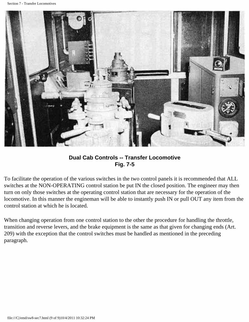
Section 7 - Transfer Locomotives
Dual Cab Controls -- Transfer Locomotive Fig. 7-5
To facilitate the operation of the various switches in the two control panels it is recommended that ALL switches at the NON-OPERATING control station be put IN the closed position. The engineer may then turn on only those switches at the operating control station that are necessary for the operation of the locomotive. In this manner the engineman will be able to instantly push IN or pull OUT any item from the control station at which he is located.
When changing operation from one control station to the other the procedure for handling the throttle, transition and reverse levers, and the brake equipment is the same as that given for changing ends (Art. 209) with the exception that the control switches must be handled as mentioned in the preceding paragraph.
file:///C|/emd/sw8-sec7.html (9 of 9)10/4/2011 10:32:24 PM

SW8 Charts
CHARTS
file:///C|/emd/sw8-app.html (1 of 4)10/4/2011 10:32:50 PM

SW8 Charts
Electrical Symbols CHART 1
LEGEND OF ELECTRICAL EQUIPMENT
The following list shows abbreviations identifying electrical equipment on the locomotive and/or wiring diagrams. The diagram wire designations conform with the identification bands on the wires in the locomotive.
The diagram shows the contactors, switches and relays as if the engine was stopped and all manual switches open. It must be remembered that when the operating coil of a contactor becomes energized the contacts and interlocks associated with the contactor will then be in a position opposite to that shown in the wiring diagram.
A Battery Charging Ammeter
BC Battery Charging Contactor
BF Battery Field Contactor
CCS Compressor Control Switch
CR Compressor Control Relay
CO Trcuk Cutout Switch
CLR Current Limit Relay
FOR Reverser Magnet Valve (Forward)
FTR Forward Transition Relay
GR Ground Relay
IS Isolation Switch
M Motor Shunting Contactor
P1,P2 Power Contactor (Series-Parallel)
PR Parallel Relay
RCR Reverse Current Relay
REV Reverse Magnet Valve (Reverse)
RVR Reverse Drum Interlock
RS Road Service Switch
S Series Power Contactor
SH Shunt Field Contactor
ST+ ST-
Starting Contactors
STS Shutter Temperature Switch
SMV Shutter Magnet Valve
file:///C|/emd/sw8-app.html (2 of 4)10/4/2011 10:32:50 PM
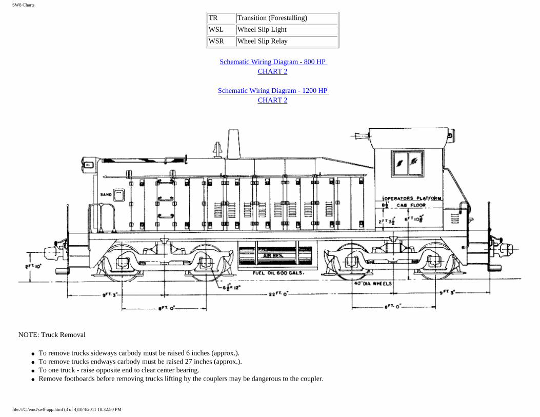
SW8 Charts
TR Transition (Forestalling)
WSL Wheel Slip Light
WSR Wheel Slip Relay
Schematic Wiring Diagram - 800 HP CHART 2
Schematic Wiring Diagram - 1200 HP CHART 2
NOTE: Truck Removal
● To remove trucks sideways carbody must be raised 6 inches (approx.). ● To remove trucks endways carbody must be raised 27 inches (approx.). ● To one truck - raise opposite end to clear center bearing. ● Remove footboards before removing trucks lifting by the couplers may be dangerous to the coupler.
file:///C|/emd/sw8-app.html (3 of 4)10/4/2011 10:32:50 PM

SW8 Charts
NOTE: Charts 4 and 5 also apply to SW9 Switcher, the only difference being the use of a 12-567B Engine in the SW9 Switcher, which requires two exhaust stacks.
SW8 Switcher Outline (Plan View) CHART 5
file:///C|/emd/sw8-app.html (4 of 4)10/4/2011 10:32:50 PM

file:///C|/emd/sw8-chart1.gif
file:///C|/emd/sw8-chart1.gif10/4/2011 10:33:11 PM

file:///C|/emd/sw8-chart2.gif
file:///C|/emd/sw8-chart2.gif10/4/2011 10:33:19 PM

file:///C|/emd/sw8-chart3.gif
file:///C|/emd/sw8-chart3.gif10/4/2011 10:33:25 PM
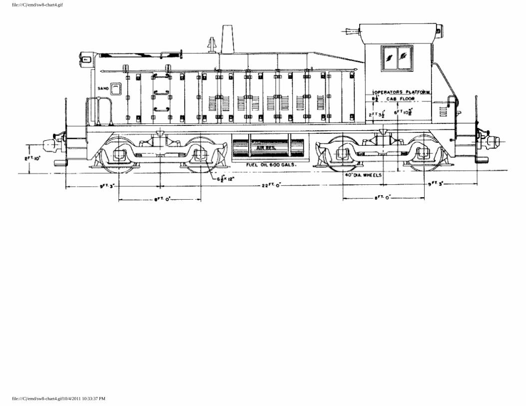
file:///C|/emd/sw8-chart4.gif
file:///C|/emd/sw8-chart4.gif10/4/2011 10:33:37 PM

file:///C|/emd/sw8-chart5.gif
file:///C|/emd/sw8-chart5.gif10/4/2011 10:33:46 PM