emergency action plan - mblp.org
TRANSCRIPT
Emergency Action PlanShiras Steam Plant Holding Pond (WDS ID #478988)City of Marquette, MichiganOwned by Marquette Board of Light and Power
Project Number: 60445171
April 13, 2017
Emergency Action Plan
K:\Projects\60445171_MBLP Shiras Steam Plant\500-Deliverables\502 FINAL EAP AECOM
Emergency Action Plan ForShiras Steam Plant Holding Pond
400East Hampton Street, Marquette, Michigan
County: Marquette
Owner: Marquette Board of Light and Power (MBLP) – Executive Director
Telephone: 906-228-0346
Cell: 906-228-0340 (24-hrs)
Operator: Shift Supervisor
Telephone: 906-228-0340
Cell: 906-228-0340 (24-hrs)
Owner Mailing Address: 2200 Wright Street
Marquette, Michigan 49855

Emergency Action Plan
K:\Projects\60445171_MBLP Shiras Steam Plant\500-Deliverables\502 FINAL EAP AECOM
Prepared for:
Mr. John SchultzMarquette Board of Light and Power2200 Wright StreetMarquette, Michigan 49855
Prepared by:Shannon Allen, P.E.
AECOM1230 Wilson StreetMarquette, Michigan 49855aecom.com
Copyright © 2017 by AECOM
Emergency Action Plan
K:\Projects\60445171_MBLP Shiras Steam Plant\500-Deliverables\502 FINAL EAP AECOM
Table of Contents1. Introduction.................................................................................................................................... 7
1.1 Purpose and Intent............................................................................................................... 71.2 EAP Summary ..................................................................................................................... 71.3 Description of Impoundment ................................................................................................ 8
2. Safety Emergency ......................................................................................................................... 92.1 Definition of Safety Emergency ............................................................................................ 92.2 EAP Response Process ....................................................................................................... 92.2.1 Incident Detection, Evaluation, and Emergency Level Determination .................................... 92.2.1.1 Non-Failure Level of Emergency ..................................................................................... 92.2.1.2 High Flow Level of Emergency ..................................................................................... 102.2.1.3 Potential Failure Level of Emergency ............................................................................ 102.2.1.4 Imminent Failure Level of Emergency ........................................................................... 102.2.2 Notification and Communication ......................................................................................... 102.2.2.1 EAP Notification Flowchart............................................................................................ 102.2.2.2 Notification to Emergency Management Authorities....................................................... 112.2.2.3 Status Updates ............................................................................................................. 112.2.3 Emergency Actions ............................................................................................................ 112.2.3.1 High Water Level .......................................................................................................... 112.2.3.2 Embankment and Sheet Pile Wall Deficiencies and Seepage ........................................ 112.2.4 Termination and Follow-Up................................................................................................. 112.2.4.1 Reentry and Recovery .................................................................................................. 112.2.4.2 After Action Review ...................................................................................................... 12
3. Hydraulic Shadow Map ................................................................................................................ 134. General Responsibilities .............................................................................................................. 14
4.1 Owner Responsibilities....................................................................................................... 144.2 Notification and Communication Responsibilities ................................................................ 144.2.1 Notification Flowchart ......................................................................................................... 144.2.2 Emergency Notification Lists .............................................................................................. 144.2.3 Media Contact ................................................................................................................... 144.3 Evacuation Responsibilities ................................................................................................ 144.4 Monitoring, Security, Termination, and Follow-up Responsibilities ....................................... 154.5 EAP Coordinator Responsibilities ....................................................................................... 15
5. Preparedness .............................................................................................................................. 165.1 Surveillance and Monitoring ............................................................................................... 165.2 Evaluation of Detection and Response Timing .................................................................... 165.3 Access to the Site .............................................................................................................. 165.4 Response During Periods of Darkness ............................................................................... 165.5 Response During Weekends and Holidays ......................................................................... 165.6 Response During Adverse Weather.................................................................................... 175.7 Alternative Sources of Power ............................................................................................. 175.8 Emergency Supplies and Information ................................................................................. 175.8.1 Materials and Equipment ................................................................................................... 175.8.2 Available Resources .......................................................................................................... 175.9 Co-ordination of Information ............................................................................................... 175.10 Annual Review, Training, and Testing ................................................................................. 175.11 Alternative Systems of Communication .............................................................................. 18
Emergency Action Plan
K:\Projects\60445171_MBLP Shiras Steam Plant\500-Deliverables\502 FINAL EAP AECOM
5.12 Public Awareness and Communication ............................................................................... 18Appendix A – Figures ............................................................................................................................... 7
A.1 Site Location Diagram .......................................................................................................... 7A.2 Site Features ....................................................................................................................... 7A.3 Holding Pond Plan and Cross Sections ................................................................................ 7
Appendix B – Charts and Tables .............................................................................................................. 8B.1 Summary of EAP Responsibilities ........................................................................................ 8B.2 Summary of Owner Responsibilities ..................................................................................... 8B.3 Guidance for Determining the Emergency Level ................................................................... 8B.4 Level of Emergency Determination Chart ............................................................................. 8B.5 Notification Flowchart ........................................................................................................... 8B.6 Available Resources Chart ................................................................................................... 8
Appendix C – Blank Forms and Log Sheets ........................................................................................... 15C.1 Concurrence ...................................................................................................................... 15C.2 List of Holders, Receipt Confirmation, and Emergency Action Plan Updates ....................... 15C.3 Emergency Incident Log .................................................................................................... 15C.4 Emergency Termination Log ............................................................................................... 15
Appendix D – Glossary .......................................................................................................................... 21
Emergency Action Plan
K:\Projects\60445171_MBLP Shiras Steam Plant\500-Deliverables\502 FINAL EAP AECOM7
1. Introduction
1.1 Purpose and Intent
This Emergency Action Plan (EAP) was developed to provide a single source of information in the eventof an emergency as required for Coal Combustion Residual (CCR) impoundments determined to beeither a high hazard potential or significant hazard potential CCR impoundment per section §257.73 ofthe U.S. Environmental Protection Agency (EPA) Final Rule: Disposal of Coal Combustion Residuals fromElectric Utilities.
The purpose of an Emergency Action Plan (EAP) is to provide the owner/operator of the CCRimpoundments with a clear plan of action when any emergency arises. An emergency is identified as anycondition which:
· Develops unexpectedly;
· Endangers the structural integrity of the impoundment; and
· Could result in the impoundment's failure, requiring immediate action.
By writing and implementing an EAP the owner/operator of the impoundment can reduce the risk ofhuman life loss or injury and minimize property damage during an unusual or emergency event.
This EAP is for the Marquette Board of Light and Power (MBLP) Shiras Steam Plant Holding Pondlocated in Marquette, Michigan. The EAP provides a description of the impoundment and the area at riskas well as contact information for all parties involved in responding to or affected by an emergency at theimpoundment. The EAP outlines what actions are required in the event of an emergency.
1.2 EAP Summary
This document includes:
· Definition of the events or circumstances involving the CCR impoundment that represent a safetyemergency and the procedures that will be followed to detect a safety emergency in a timely manner.
· Site location map delineating the downstream area which would be affected in the event of a CCRimpoundment failure.
· Contact telephone numbers for individuals that must be contacted in the event of an emergency, theirrespective responsibilities, and notification procedures.
· Procedures following an emergency at the impoundment.
· Provisions for an annual face-to-face meeting or exercise between representatives of the CCRimpoundment and the local emergency responders.
The plan will be implemented once events or circumstances involving the CCR impoundment represent asafety emergency is detected, including conditions identified during periodic structural stabilityassessments, annual inspections, and inspections by a qualified person. The responsibilities forresponding to an incident and implementing the plan are included in the Summary of EAP Responsibilitiesand Summary of Owner Responsibilities in Appendix B. One copy of this plan will be kept at the ShirasSteam Plant.
The plan will be amended by the owner or operator of the CCR impoundment whenever there is a changein conditions that would substantially affect the EAP in effect. This plan will, at a minimum, be evaluatedevery five years to ensure the information required is accurate. If the owner or operator of the CCRimpoundment determines during a periodic hazard potential assessment that the CCR impoundment is nolonger classified as a significant hazard potential CCR impoundment, then the owner or operator is nolonger subject to the requirement to prepare and maintain a written EAP.

Emergency Action Plan
K:\Projects\60445171_MBLP Shiras Steam Plant\500-Deliverables\502 FINAL EAP AECOM8
1.3 Description of Impoundment
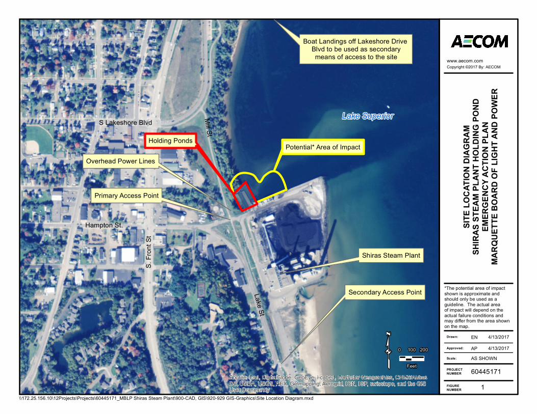
The Shiras Steam Plant is located at East Hampton Street in Marquette, Michigan along the shoreline ofLake Superior. The Shiras Steam Plant generating station has one CCR surface impoundment identifiedherein as the Holding Pond. The Holding Pond is located north of the generating station. The location ofthe impoundment is shown on the Site Location Diagram included in Appendix A.
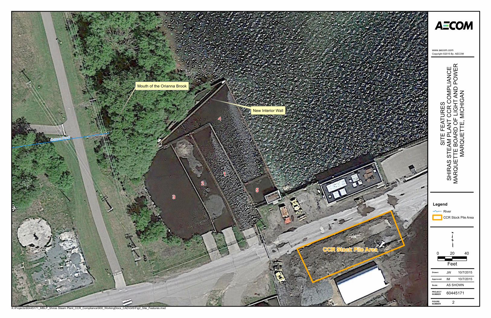
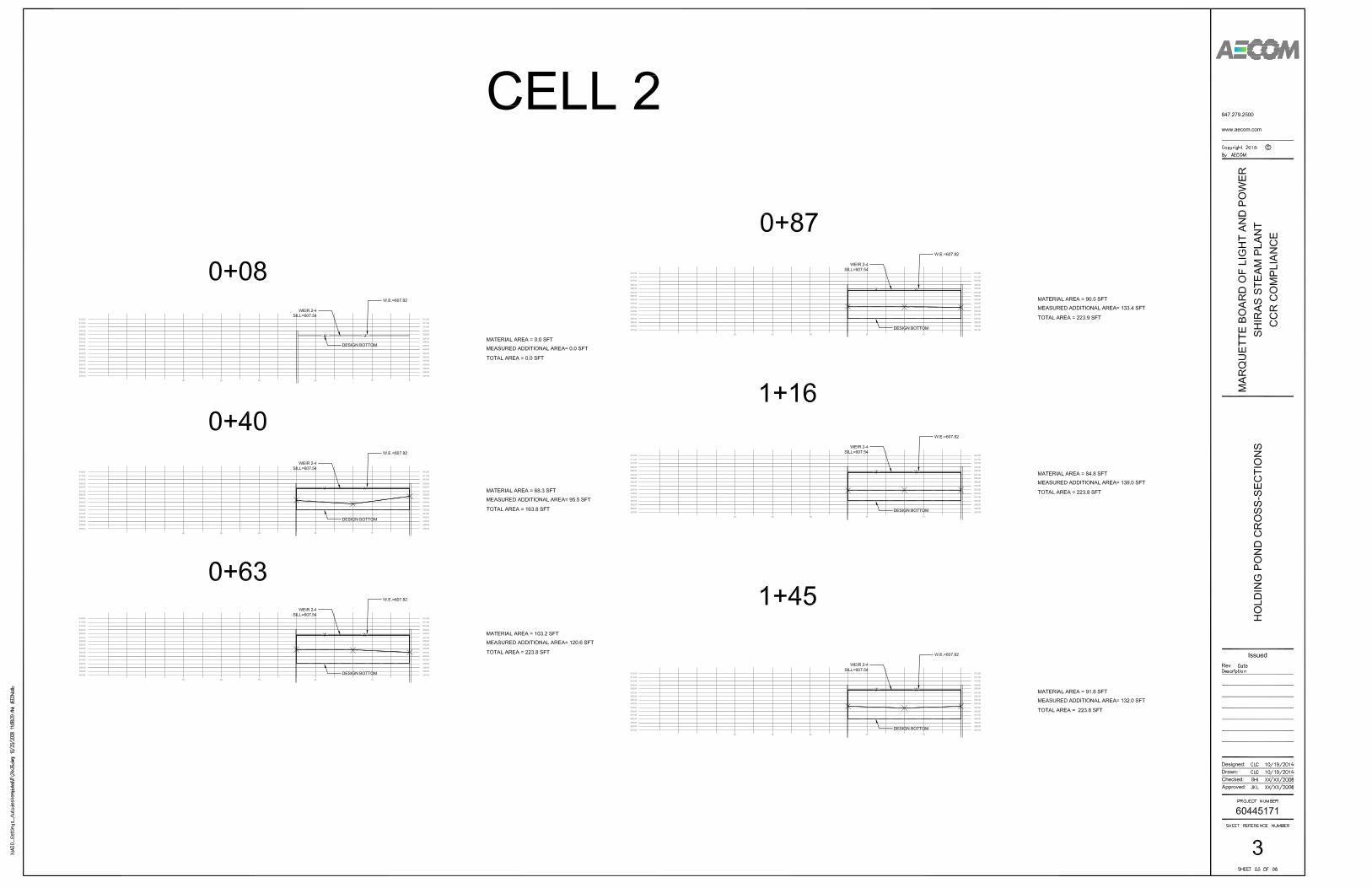
The Holding Pond is composed of 5 interconnected cells which are enclosed by steel sheet pile walls andare in hydraulic communication via a set of weirs built into the walls. The south and west boundaries ofthe Holding Pond are formed by the shoreline of Lake Superior. The east and north boundaries areformed by sheet pile walls originally constructed in 1981. A new wall was placed on the inside of theexisting north wall in 2013 due to the poor condition of the original wall. Inner walls for Cells 1, 2, and 3were constructed in 1990. Abandoned sheet pile walls also remain in place from previous configurations.
The Holding Pond is operated as a zero-discharge facility during normal conditions and does notdischarge water. All water discharged to the Holding Pond via sluicing or precipitation is held within theponds, pumped to a 300,000 gallon equalization/reuse storage tank, and/or recirculated to the plant. Low,medium, and high service water pumps recycle the reclaimed water for plant use. The normal operatinglevel of the holding pond varies, but is approximately at elevation 606.0 feet IGLD85. All elevations aregiven according to the International Great Lakes Datum of 1985 (IGLD85), unless noted otherwise.During emergency situations, an outfall weir at elevation 606.6 feet and an emergency overflow weir atelevation 607.4 feet, which are regulated via a NPDES permitted outfall (#004A), discharge water fromthe Holding Pond through the east wall directly into Lake Superior. However, discharge from the pond hasbeen reserved for emergency situations and there have reportedly been only three to five discharges inthe last fifteen years. The north and east perimeter sheet pile wall top elevation is 609.0 feet. The ordinaryhigh water surface elevation of Lake Superior is 603.1feet as evaluated by the United States Army Corpsof Engineers Detroit District. Additional information for the Holding Pond is provided in Table 1.
Table 1. CCR Surface Impoundment Description
Information Holding Pond(WDS ID#478988)
Type of Impoundment Combination of Earthenand Steel Sheet Pile Wall
Height of Impoundment 9 to 11 feet
Max Impoundment Storage 5,750 cubic yards
Use of Impoundment CCR Operations
Hazard Rating Significant
AECOM prepared a hazard potential classification assessment in October 2016 for the CCR surfaceimpoundment. Significant upstream and downstream features which could be affected by a failure areincluded on the Location Map included in Appendix A.

Emergency Action Plan
K:\Projects\60445171_MBLP Shiras Steam Plant\500-Deliverables\502 FINAL EAP AECOM9
2. Safety Emergency
2.1 Definition of Safety Emergency
A safety incident is an impending or actual sudden uncontrolled release or excessive controlled release(outside of the permitted allowances) of water from the Holding Pond. The release may be caused bydamage to or failure of the structure, flood conditions unrelated to failure, or any condition that may affectsafe operation. The release of water may or may not endanger human life, downstream property, or theoperation of the structure.
2.2 EAP Response Process
There are generally four steps that should be followed when an unusual or emergency incident isdetected. The steps constitute the EAP response process and are as follows:
1. Incident detection, evaluation, and emergency level determination
2. Notification and communication
3. Emergency Actions
4. Termination and follow-up
These steps are discussed further in the following subsections.
2.2.1 Incident Detection, Evaluation, and Emergency Level Determination
An incident would be considered an unusual or abnormal condition and could be observed using thefollowing:
1. Detecting existing or potential failures.
2. Measuring water level. Normal water level within the impoundments should be below elevation 606.6feet (outfall weir elevation), which is 2.4 feet below the design crest elevation of 609.0 feet.
3. Reviewing monitoring equipment such as movement monitoring targets.
4. Checking instrumentation.
5. Analyzing and confirming data.
After an unusual event or incident is detected and confirmed, the event should be categorized into one ofthe established emergency levels based on the severity of the initiating condition or triggering events. Thelevels of emergency are:
· Non-Failure
· High Flow
· Potential Failure
· Imminent Failure
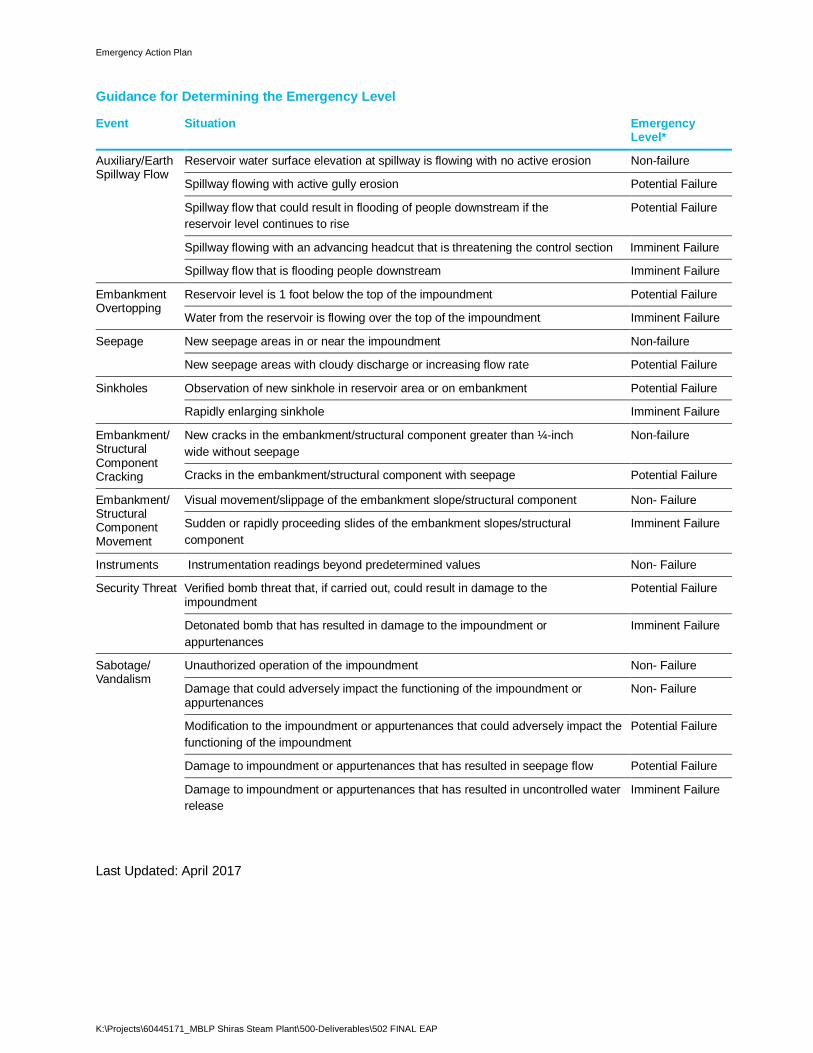
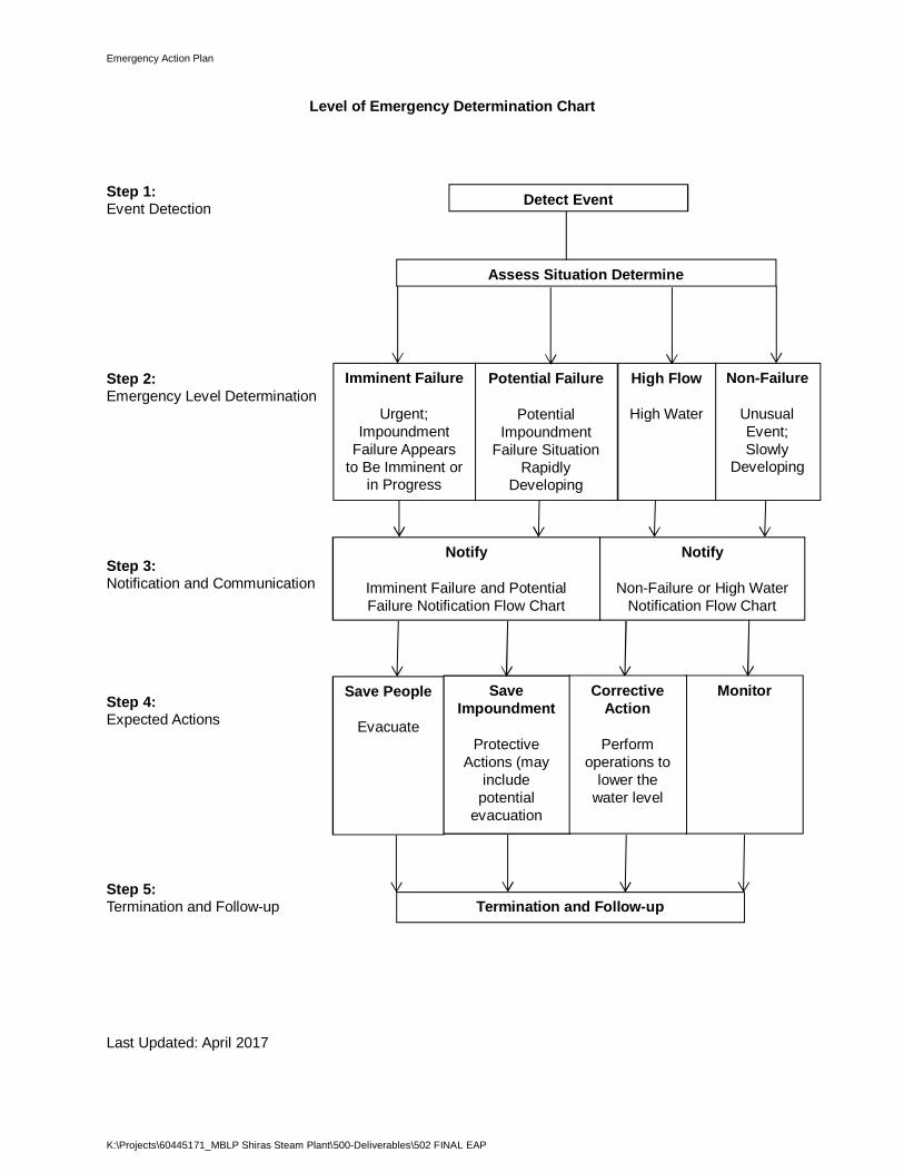
It is important to determine the severity of the emergency before responding to an unusual event at theimpoundments. The Guidance for Determining the Emergency Level table and Level of EmergencyDetermination Chart included in Appendix B are to be used to determine the severity of the emergencyand to guide the owner/operator’s actions during an emergency response. Descriptions of the levels ofemergency are provided in the following subsections.
2.2.1.1 Non-Failure Level of Emergency
The Non-Failure emergency level is appropriate for an event that will not, by itself, lead to a failure, butrequires investigation and notification of internal and/or external personnel. Examples are:

Emergency Action Plan
K:\Projects\60445171_MBLP Shiras Steam Plant\500-Deliverables\502 FINAL EAP AECOM10
1. New seepage or leakage on the downstream side of the impoundment.
2. Presence of unauthorized personnel.
3. Malfunction of a gate.
Some incidents may only require internal response, whereas others may lead to unexpected highreleases that could pose a hazard to the downstream public and would require the notification of outsideagencies.
2.2.1.2 High Flow Level of Emergency
The High Flow emergency level indicates that flooding is occurring on the system, but there is noapparent threat to the integrity of the impoundment. The High Flow emergency level is used by the ownerto convey to internal resources that downstream areas may be affected by the impoundment’s releaseand close monitoring of the situation is warranted. Although the amount of flooding may be beyond thecontrol of the owner, information on the timing and amount of release from the impoundment may behelpful to authorities in making decisions regarding warnings and evacuations.
2.2.1.3 Potential Failure Level of Emergency
The Potential Failure emergency level indicates that conditions are developing that could lead to a failure.Examples are:
1. Rising reservoir levels that are approaching the top of the non-overflow section of the impoundment.
2. A verified security threat.
3. Wave action from Lake Superior.
Potential Failure should convey that time is available for analyses, decisions, and actions before theimpoundment could fail. A failure may occur, but predetermined response actions may moderate oralleviate failure.
2.2.1.4 Imminent Failure Level of Emergency
The Imminent Failure emergency level indicates that time has run out, and the impoundment has failed, isfailing, or is about to fail. Imminent Failure typically involves a continuing and progressive loss of materialfrom the impoundment. It is not usually possible to determine how long a complete breach of theimpoundment will take. Therefore, once a decision is made that there is no time to prevent failure, theImminent Failure warning must be issued. For purposes of evacuation, emergency managementauthorities may assume the worst-case condition that failure has already occurred.
2.2.2 Notification and Communication
2.2.2.1 EAP Notification Flowchart
After the emergency level at the impoundment has been determined, notifications are made inaccordance with the EAP Notification Flowchart. The purpose of the EAP Notification Flowchart is toprovide a visual map of who is to be notified the order of notification and who is responsible for notifyingvarious individuals and agencies/organizations. The Notification Flowchart can be customized based onthe level of emergency as determined under the Level of Emergency Determination Chart.
The Emergency Action Plan Notification Flowchart for the Holding Pond can be found in Appendix B andwas last updated on the date shown on the bottom of the page. The Notification Flowchart will beactivated with a telephone call to the Shiras Steam Plant Shift Supervisor. Contact with the local lawenforcement will be maintained throughout the emergency by phone. See Appendix B for the EmergencyCommunication Plan.
Emergency Action Plan
K:\Projects\60445171_MBLP Shiras Steam Plant\500-Deliverables\502 FINAL EAP AECOM11
2.2.2.2 Notification to Emergency Management Authorities
When performing notification and communication activities, it is important that people speak in clear,nontechnical terms to ensure those being notified understand what is happening, what the currentemergency level is, and which actions to take. To assist in this step, prescripted messages to help thecaller adequately describe the emergency situation to emergency management authorities are includedon the Notification Flowcharts included in Appendix B.
2.2.2.3 Status Updates
After initial notification, the owner should make periodic status reports to the affected emergencyauthorities and other stakeholders in accordance with the Notification Flowcharts. If it appears that thesituation is continuing to deteriorate despite actions being taken to moderate or alleviate the failure, localauthorities may decide to change their course of action.
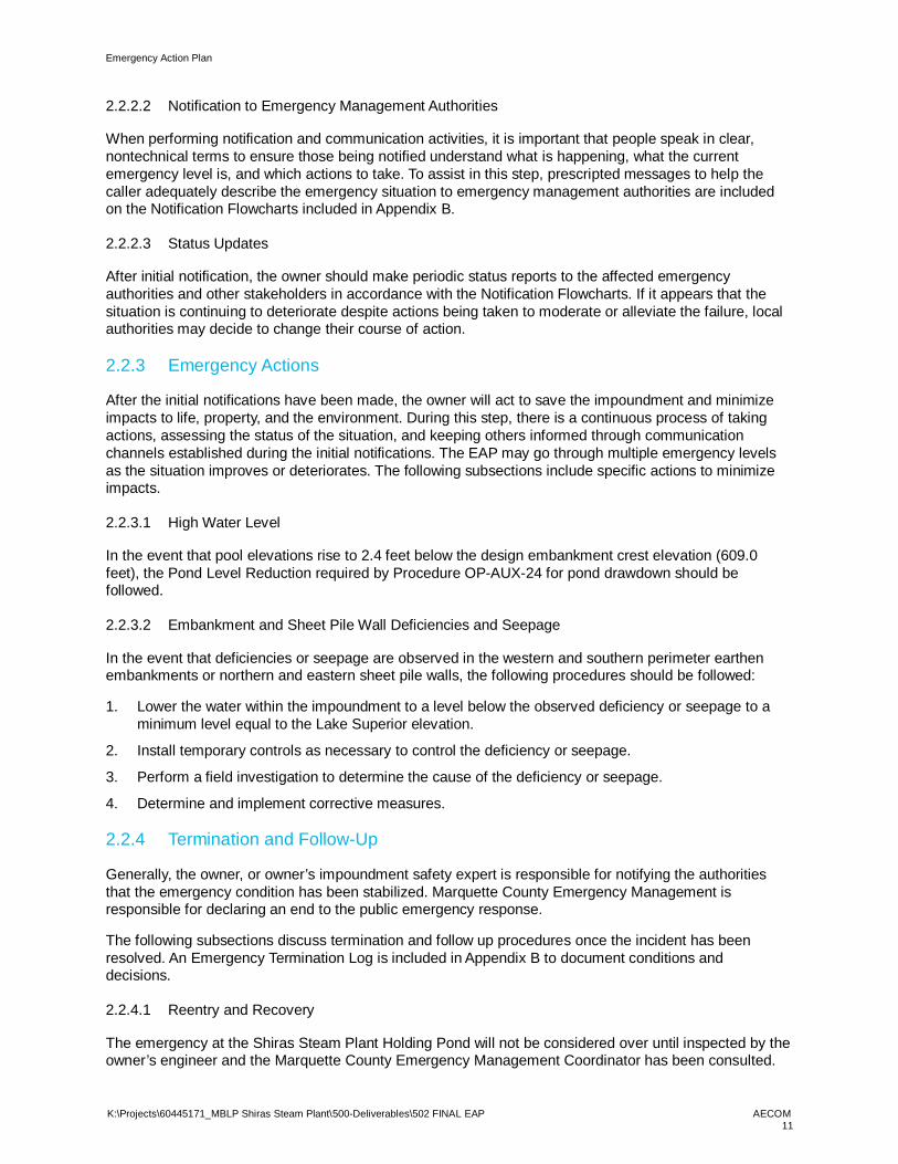
2.2.3 Emergency Actions
After the initial notifications have been made, the owner will act to save the impoundment and minimizeimpacts to life, property, and the environment. During this step, there is a continuous process of takingactions, assessing the status of the situation, and keeping others informed through communicationchannels established during the initial notifications. The EAP may go through multiple emergency levelsas the situation improves or deteriorates. The following subsections include specific actions to minimizeimpacts.
2.2.3.1 High Water Level
In the event that pool elevations rise to 2.4 feet below the design embankment crest elevation (609.0feet), the Pond Level Reduction required by Procedure OP-AUX-24 for pond drawdown should befollowed.
2.2.3.2 Embankment and Sheet Pile Wall Deficiencies and Seepage
In the event that deficiencies or seepage are observed in the western and southern perimeter earthenembankments or northern and eastern sheet pile walls, the following procedures should be followed:
1. Lower the water within the impoundment to a level below the observed deficiency or seepage to aminimum level equal to the Lake Superior elevation.
2. Install temporary controls as necessary to control the deficiency or seepage.
3. Perform a field investigation to determine the cause of the deficiency or seepage.
4. Determine and implement corrective measures.
2.2.4 Termination and Follow-Up
Generally, the owner, or owner’s impoundment safety expert is responsible for notifying the authoritiesthat the emergency condition has been stabilized. Marquette County Emergency Management isresponsible for declaring an end to the public emergency response.
The following subsections discuss termination and follow up procedures once the incident has beenresolved. An Emergency Termination Log is included in Appendix B to document conditions anddecisions.
2.2.4.1 Reentry and Recovery
The emergency at the Shiras Steam Plant Holding Pond will not be considered over until inspected by theowner’s engineer and the Marquette County Emergency Management Coordinator has been consulted.
Emergency Action Plan
K:\Projects\60445171_MBLP Shiras Steam Plant\500-Deliverables\502 FINAL EAP AECOM12
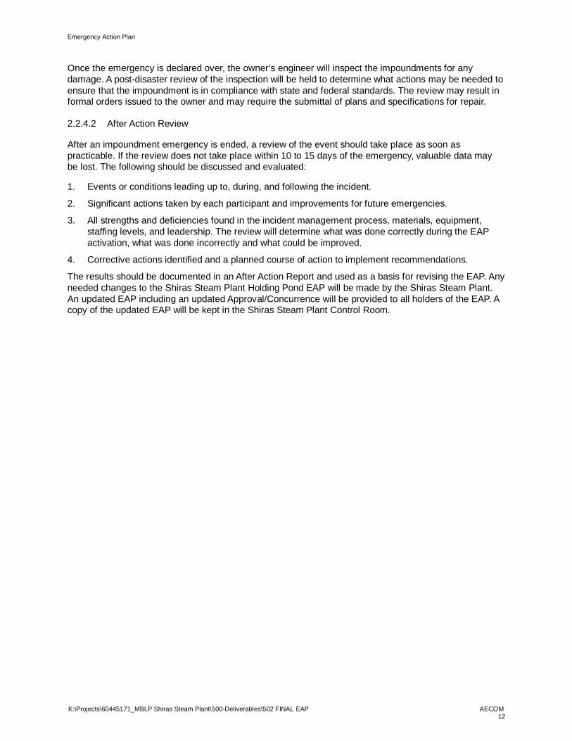
Once the emergency is declared over, the owner’s engineer will inspect the impoundments for anydamage. A post-disaster review of the inspection will be held to determine what actions may be needed toensure that the impoundment is in compliance with state and federal standards. The review may result informal orders issued to the owner and may require the submittal of plans and specifications for repair.
2.2.4.2 After Action Review
After an impoundment emergency is ended, a review of the event should take place as soon aspracticable. If the review does not take place within 10 to 15 days of the emergency, valuable data maybe lost. The following should be discussed and evaluated:
1. Events or conditions leading up to, during, and following the incident.
2. Significant actions taken by each participant and improvements for future emergencies.
3. All strengths and deficiencies found in the incident management process, materials, equipment,staffing levels, and leadership. The review will determine what was done correctly during the EAPactivation, what was done incorrectly and what could be improved.
4. Corrective actions identified and a planned course of action to implement recommendations.
The results should be documented in an After Action Report and used as a basis for revising the EAP. Anyneeded changes to the Shiras Steam Plant Holding Pond EAP will be made by the Shiras Steam Plant.An updated EAP including an updated Approval/Concurrence will be provided to all holders of the EAP. Acopy of the updated EAP will be kept in the Shiras Steam Plant Control Room.
Emergency Action Plan
K:\Projects\60445171_MBLP Shiras Steam Plant\500-Deliverables\502 FINAL EAP AECOM13
3. Hydraulic Shadow MapThe purpose of the Hydraulic Shadow Map, or inundation map, is to provide a picture of the area thatwould be affected by a complete failure of the impoundment in order to determine who must be notifiedand/or evacuated in an emergency and the timeliness to facilitate notification and evacuation. TheHydraulic Shadow Map identifies individuals and other infrastructure such as building, bridges, roads,power lines, sewer, gas and water lines that could be affected by the failure of the impoundment.
Due to the site configuration and topography, a site specific Hydraulic Shadow Map showing inundationzones was not produced. In the unlikely event there is a failure, the impounded water would either bereleased directly into Lake Superior to the north or onto a generally unoccupied portion of land to the westwhich would then drain directly to Lake Superior. Adjacent streets, buildings, and other significant featuresare indicated on the Site Location Diagram included in Appendix A. Primary and Secondary points ofaccess to the site are also included on the map.
Emergency Action Plan
K:\Projects\60445171_MBLP Shiras Steam Plant\500-Deliverables\502 FINAL EAP AECOM14
4. General ResponsibilitiesThe owner is responsible for developing and maintaining the EAP. Owners and emergency managementauthorities are responsible for implementing the EAP. The Emergency Incident Log form in Appendix Cshould be used to document incident-related events by all entities involved with EAP implementation. Thefollowing subsections specify the responsibilities of all entities to ensure that effective and timely action istaken if an emergency occurs.
4.1 Owner Responsibilities
The owner is responsible for detecting and evaluating the safety incident, classifying the incident,notifying emergency management authorities, and taking appropriate response actions. Refer to Section2.2.3 of this EAP for operator duties for given emergency response situations.
4.2 Notification and Communication Responsibilities
4.2.1 Notification Flowchart
Notifications are made in accordance with the EAP Notification Flowchart. Refer to Section 2.2.2.1 of thisEAP for additional information and the Notification Flowchart in Appendix B.
4.2.2 Emergency Notification Lists
Emergency Notification Lists are lists of the names, addresses and telephone numbers of individuals,businesses, critical facilities and other entities who would be affected by a failure of the impoundmentsand who must be notified and/or evacuated in an emergency. The lists have been grouped based on theseverity of the emergency. The Emergency Notification Lists for the Shiras Steam Plant Holding Pond canbe found on the Notification Flowchart included in Appendix B and were last updated on the date shownon the bottom of the page.
4.2.3 Media Contact
Interaction with the media should be implemented through the local or State emergency managementauthority. These agencies should have a Public Information Officer (PIO) and/or a Joint InformationCenter for disseminating information and handling inquiries.
Local emergency management authorities may activate an Emergency Operations Center (EOC) to serveas a central co-ordination center for emergency response, warning, and evacuation activities. The owneror their representative should go to the EOC to help agency personnel understand the project specificinformation and inundation maps.
Proper co-ordination and communication between the on-site technical personnel, PIOs and emergencypersonnel at the EOC are of critical importance to the successful implementation of the EAP. Theseactivities should be thoroughly tested during comprehensive EAP exercises and modified as necessary.
4.3 Evacuation Responsibilities
Warning and evacuation planning and implementation are responsibilities of local emergencymanagement authorities with the legal authority to perform these actions. Under the EAP, the owner isresponsible for notifying the appropriate emergency management authority when an incident isanticipated, is imminent, or has occurred.
Owners should not assume or usurp the responsibility of government entities for evacuation of people.However, there may be situations in which routine notification and evacuation will not be sufficient. Insome cases, owners may arrange to notify affected individuals directly. Such procedures should becoordinated with the appropriate authorities before an emergency situation develops.
Emergency Action Plan
K:\Projects\60445171_MBLP Shiras Steam Plant\500-Deliverables\502 FINAL EAP AECOM15
4.4 Monitoring, Security, Termination, and Follow-up Responsibilities
A person should be designated as an onsite monitor from the beginning of a safety incident until theemergency has been terminated. This person should provide status updates to the owner so the ownercan keep all those involved with the implementation of the EAP informed of developing conditions.
Termination of a safety emergency is usually twofold. The entity that activates the EAP is usuallyresponsible for determining when the safety situation has stabilized. This is typically the owner inconsultation with engineers and safety experts but may include other State and Federal regulatoryentities. The applicable emergency management authorities, on the other hand, are responsible fortermination of the emergency response activities, including termination of an evacuation. Both the ownerand the emergency response authorities should coordinate closely while making decisions to terminateboth the safety event and response efforts.
Recovery activities will continue on different levels for all involved in the safety incident after theemergency has been terminated.
The owner should coordinate a follow-up evaluation after any emergency. All participants should beinvolved in this evaluation and should keep logs and records during the incident. An Emergency IncidentLog and Emergency Termination Log are included in Appendix C. The results of the follow-up evaluationshould be documented in a written report (After Action Report) and used to improve future responseactions.
4.5 EAP Coordinator Responsibilities
The EAP Coordinator will be responsible for overall EAP-related activities, including but not limited topreparing revisions to the EAP, establishing training seminars, and coordinating EAP exercises. TheShiras Steam Plant Holding Pond EAP coordinator is the Executive Director, who is also the EAP contactfor questions about the plan.

Emergency Action Plan
K:\Projects\60445171_MBLP Shiras Steam Plant\500-Deliverables\502 FINAL EAP AECOM16
5. PreparednessPreparedness typically consists of activities and actions taken before the development of an incident.Preparedness activities attempt to facilitate response to an incident as well as prevent, moderate, oralleviate the effects of the incident. The following subsections relate to preparedness actions.
5.1 Surveillance and Monitoring
Prompt detection and evaluation of information from instrumentation and physical monitoring is critical tothe effectiveness of the EAP and timely emergency response.
The water level in the pond is monitored via ultrasonic instrumentation in cell 5 on a continuous basis.Data is provided to the operations personnel via the Distributed Control System (DCS). An alarm isgenerated when the pond level rises prior to discharge so that pond drawdown procedures can beimplemented. A second alarm is generated at the point of discharge. Movement monitoring targets wereinstalled in October 2015 near the top of the sheet pile walls to check for horizontal movement. Readingsare taken on a yearly basis and would be compared over time to monitor for stability issues.
AECOM performed a structural inspection and analysis of the Holding Pond in 2013. Subsequentinspections were completed by AECOM in December 2015 and December 2016. No seepage wasevident during the evaluation. The east steel sheet pile wall of the holding pond was observed to be infairly good condition and the north sheet pile wall was observed to be in excellent condition during thestructural analysis. The south and west sides of the Holding Pond are incised into the ground and wereconsidered to pose no threat of failure during the structural inspection.
5.2 Evaluation of Detection and Response Timing
Total EAP implementation time from the initiation of an actual incident to determination of an emergencysituation and is adequate based on continuous monitoring and rapid detection procedures in place.
5.3 Access to the Site
The primary access to reach the site by vehicle in Marquette is from South Front Street to East HamptonStreet. In the event that the entrance at East Hampton Street is blocked, there is a secondary plantentrance off South Lake Street from South Front Street. Access to the site from local police and firedepartments is anticipated to take about 5 to 10 minutes from both the primary and secondary route.
Several boat launches for Lake Superior, including the US Coast Guard office, are located just north ofthe site along North Lakeshore Boulevard and could be used as a secondary means of access to the siteif necessary.
Primary and secondary access routes for reaching the site are shown on the site location map included inAppendix A.
5.4 Response During Periods of Darkness
The Shiras Steam Plant Holding Pond does not have any on-site lighting around the impoundment. If anevent is identified during periods of darkness, action could be taken to illuminate the area where failurescould occur, if necessary. During a power failure, on-site backup generators or rented generators could beused to operate equipment where manual operation is not feasible.
5.5 Response During Weekends and Holidays
The Shiras Steam Plant is operated 24 hours a day, 7 days a week. The phone number provided in theNotification Flowchart for the Shift Supervisor is manned 24-hours a day. Therefore, no special responseis needed during weekends and holidays. Normal procedures should be followed.
Emergency Action Plan
K:\Projects\60445171_MBLP Shiras Steam Plant\500-Deliverables\502 FINAL EAP AECOM17
5.6 Response During Adverse Weather
The Shiras Steam Plant is operated 24 hours a day, 7 days a week. Therefore, no special response isneeded during adverse weather. Normal procedures should be followed. Refer to Section 5.3 for primaryand secondary access to the site.
5.7 Alternative Sources of Power
Alternative sources of power are available on-site, which include portable gas powered generators.
5.8 Emergency Supplies and Information
Planning and organizational measures that can help the owner and emergency management authoritiesmanage an emergency situation more safely and effectively include stockpiling materials, as a situation isdeveloping, and equipment for emergency use and coordinating information between organizations.
5.8.1 Materials and Equipment
In the event of a high water excursion event that could result in an impoundment failure, on-site low,medium, and high pumps will be used by plant staff to direct water to the equalization/reuse storagetanks. In the event the equalization/reuse storage tanks are full and water continues to rise, water willdischarge through the outfall weirs located on the east side of the impoundment. Additional pumps maybe required to be rented and operated by plant staff should the water continue to rise above theemergency outlet weir.
In the event of embankment or sheet pile wall deficiencies, water within the impoundments should belowered by plant operators below the observed deficiency using the pumping system currently in placeunless those systems are not able to address the issue efficiently. In those situations, additional pumpingequipment should be rented and excess water could be discharged to the sanitary sewer. Temporarycontrols such as sand, rip rap, and sheet pile may be installed by an outside contractor to control thedeficiency, and earth moving or sheet pile installation equipment may be necessary for address correctivemeasures following a field investigation. Earth moving or sheet pile installation equipment is anticipated tobe operated by a contractor hired to perform repairs to the impoundment.
Due to site constraints, additional material and equipment is not stockpiled on-site, but as stated above,can be brought in as a situation develops.
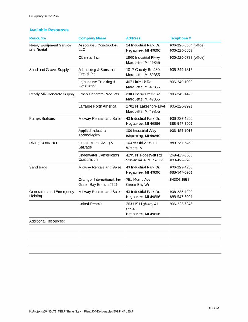
5.8.2 Available Resources
During an emergency, the owners/operators may need to bring in outside resources such as heavyequipment, sandbags, pumps, siphons or divers. A listing of the resources including provider names,addresses and telephone numbers available to the owner/operator of the Shiras Steam Plant HoldingPond can be found in Appendix B and was last updated on the date shown on the bottom of the page.
5.9 Co-ordination of Information
Refer to the Notification Flowchart in Appendix B when informing responsible parties of an emergency.
Information on weather should be obtained from the National Weather Service (NWS) athttp://www.weather.gov/ or by phone at 317-856-0367. Co-ordination with the NWS is recommended tomonitor storms, Lake Superior and river stages, and flood waves resulting from a failure.
5.10 Annual Review, Training, and Testing
The EAP should be reviewed on an annual basis to ensure that all contact information listed is accurateand that personnel are familiar with the EAP and understand their role in responding to an emergency.

Emergency Action Plan
K:\Projects\60445171_MBLP Shiras Steam Plant\500-Deliverables\502 FINAL EAP AECOM18
Training and exercise plans should be designed and developed by those entities with responsibilitiesidentified in the EAP. EAP action items and procedures should be exercised periodically for all individualsinvolved in its implementation so that individuals are familiar with their roles and responsibilities. Reviewof and training for the Shiras Steam Plant Holding Pond’s EAP will occur on an annual basis. Based onchanges identified in the annual review, copies of updated pages will be provided to all holders of theEAP. A copy of the most current EAP will be kept in the Shiras Steam Plant control room.
At least every five (5) years, the owner/operator of the Shiras Steam Plant Holding Pond will meet withthe Marquette County Emergency Management Coordinator to discuss what changes have been made tothe Marquette County All Hazards Emergency Response/Operations Plan and to determine whatopportunities exist for exercises. Also, the owner/operator of the Shiras Steam Plant Holding Pond willreview the Site Location Diagram to identify any significant land use changes in the hazard area.
The owner/operator should work with local emergency management to determine what opportunities existto conduct or participate in impoundment related EAP exercises.
5.11 Alternative Systems of Communication
The list below provides information on the forms of communication that are available at the Shiras SteamPlant Holding Pond and operating procedures during an emergency event:
· Gaitronics facility paging system: to be used as primary communication to alert Shiras Steam Plantpersonnel.
· Phones: to be used to communicate with Shiras Steam Plant personnel and outside entities
· Email: to be used as backup or follow up communication
· Intranet: to be used to update Shiras Steam Plant personnel
· Radios: to be used as a secondary communication to phones, where appropriate
5.12 Public Awareness and Communication
Lake Superior is located downstream of the Shiras Steam Plant Holding Pond. Although there are noresidences located downstream of the Holding Pond, public awareness measures include postingrequired documents in the operating record. Emergency management authorities will convey necessaryinformation to the public during an event as necessary.

Emergency Action Plan
K:\Projects\60445171_MBLP Shiras Steam Plant\500-Deliverables\502 FINAL EAP
Appendix A – Figures
A.1 Site Location Diagram
A.2 Site Features
A.3 Holding Pond Plan and Cross Sections
Lake Superior
Source: Esri, DigitalGlobe, GeoEye, i-cubed, Earthstar Geographics, CNES/AirbusDS, USDA, USGS, AEX, Getmapping, Aerogrid, IGN, IGP, swisstopo, and the GISUser Community
Drawn:
Approved:
Scale:
PROJECTNUMBER
FIGURENUMBER
EN 4/13/2017
AP 4/13/2017AS SHOWN
604451711
0 100 200
Feetq
www.aecom.comCopyright ©2017 By: AECOM
\\172.25.156.10\12Projects\Projects\60445171_MBLP Shiras Steam Plant\900-CAD, GIS\920-929 GIS-Graphics\Site Location Diagram.mxd
SITE L
OCAT
ION
DIAG
RAM
SHIR
AS ST
EAM
PLAN
T HOL
DING
POND
EMER
GENC
Y ACT
ION
PLAN
MARQ
UETT
E BOA
RD O
F LIG
HT AN
D PO
WER
Shiras Steam Plant
Boat Landings off Lakeshore Drive Blvd to be used as secondarymeans of access to the site
Hampton St.
S. Fro
nt St
S Lakeshore Blvd Mill St
Lake St
Primary Access Point
Secondary Access Point
Overhead Power LinesPotential* Area of Impact
Holding Ponds
*The potential area of impact shown is approximate and should only be used as a guideline. The actual area of impact will depend on the actual failure conditions and may differ from the area shownon the map.
12
3
4
5
New Interior Wall
Mouth of the Orianna Brook
CCR Stock Pile Area
Orianna Brook
Drawn:
Approved:
Scale:
PROJECTNUMBER
FIGURENUMBER
JW 10/7/2015IM 10/7/2015AS SHOWN
604451712
www.aecom.comCopyright ©2015 By: AECOM
K:\Projects\60445171_MBLP_Shiras Steam Plant_CCR_Compliance\900_WorkingDocs_CAD\GIS\Fig2_Site_Features.mxd
SITE
FEAT
URES
SHIR
AS ST
EAM
PLAN
T CCR
COM
PLIAN
CEMA
RQUE
TTE
BOAR
D OF
LIGH
T AND
POWE
RMA
RQUE
TTE,
MIC
HIGA
N
p0 20 40
Feet
LegendRiverCCR Stock Pile Area


Emergency Action Plan
K:\Projects\60445171_MBLP Shiras Steam Plant\500-Deliverables\502 FINAL EAP
Appendix B – Charts and Tables
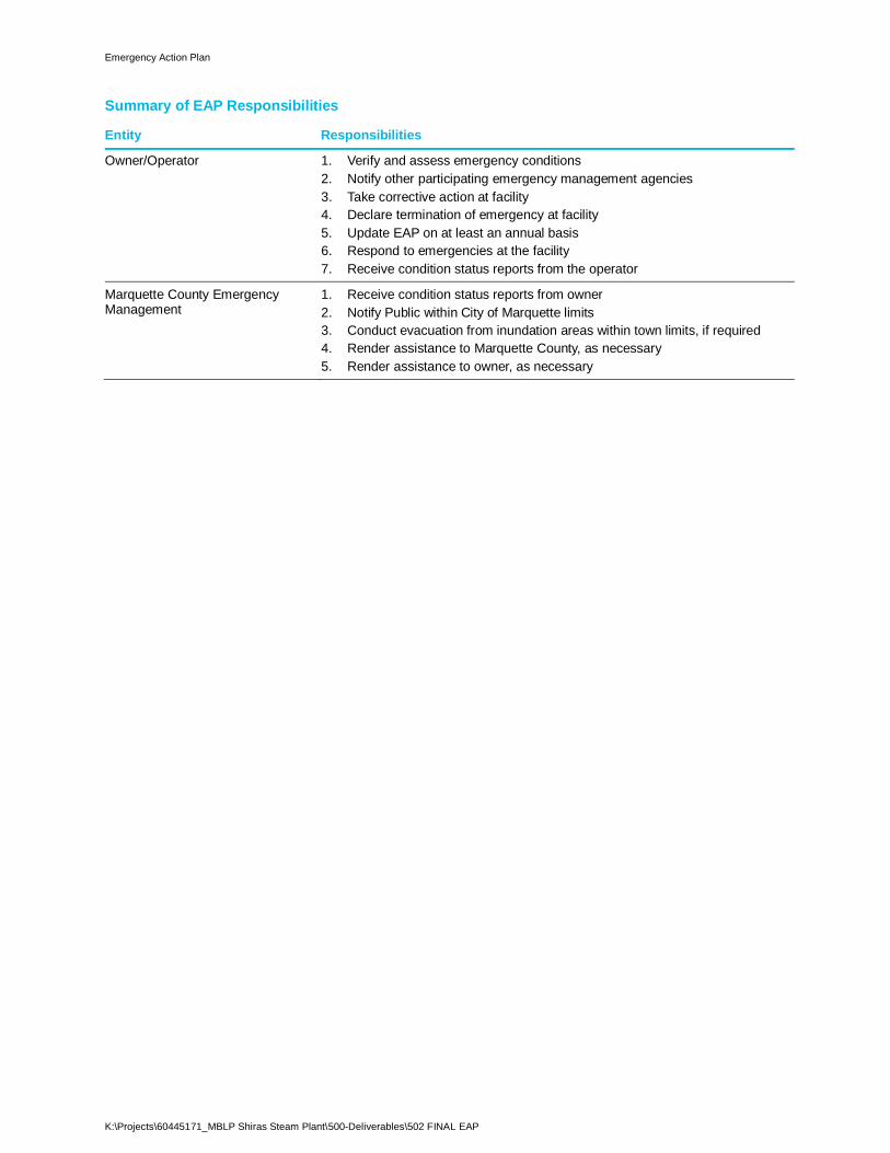
B.1 Summary of EAP Responsibilities
B.2 Summary of Owner Responsibilities
B.3 Guidance for Determining the Emergency Level
B.4 Level of Emergency Determination Chart
B.5 Notification Flowchart
B.6 Available Resources Chart
Emergency Action Plan
K:\Projects\60445171_MBLP Shiras Steam Plant\500-Deliverables\502 FINAL EAP
Summary of EAP Responsibilities
Entity Responsibilities
Owner/Operator 1. Verify and assess emergency conditions2. Notify other participating emergency management agencies3. Take corrective action at facility4. Declare termination of emergency at facility5. Update EAP on at least an annual basis6. Respond to emergencies at the facility7. Receive condition status reports from the operator
Marquette County EmergencyManagement
1. Receive condition status reports from owner2. Notify Public within City of Marquette limits3. Conduct evacuation from inundation areas within town limits, if required4. Render assistance to Marquette County, as necessary5. Render assistance to owner, as necessary
Emergency Action Plan
K:\Projects\60445171_MBLP Shiras Steam Plant\500-Deliverables\502 FINAL EAP
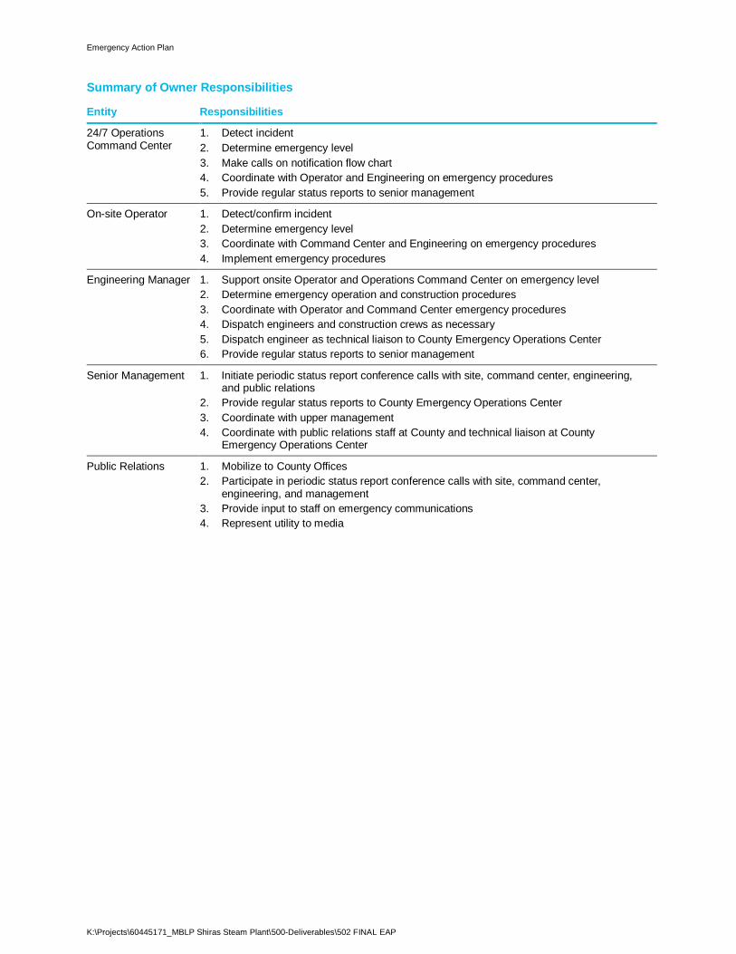
Summary of Owner Responsibilities
Entity Responsibilities
24/7 OperationsCommand Center
1. Detect incident2. Determine emergency level3. Make calls on notification flow chart4. Coordinate with Operator and Engineering on emergency procedures5. Provide regular status reports to senior management
On-site Operator 1. Detect/confirm incident2. Determine emergency level3. Coordinate with Command Center and Engineering on emergency procedures4. Implement emergency procedures
Engineering Manager 1. Support onsite Operator and Operations Command Center on emergency level2. Determine emergency operation and construction procedures3. Coordinate with Operator and Command Center emergency procedures4. Dispatch engineers and construction crews as necessary5. Dispatch engineer as technical liaison to County Emergency Operations Center6. Provide regular status reports to senior management
Senior Management 1. Initiate periodic status report conference calls with site, command center, engineering,and public relations
2. Provide regular status reports to County Emergency Operations Center3. Coordinate with upper management4. Coordinate with public relations staff at County and technical liaison at County
Emergency Operations Center
Public Relations 1. Mobilize to County Offices2. Participate in periodic status report conference calls with site, command center,
engineering, and management3. Provide input to staff on emergency communications4. Represent utility to media
Emergency Action Plan
K:\Projects\60445171_MBLP Shiras Steam Plant\500-Deliverables\502 FINAL EAP
Guidance for Determining the Emergency Level
Event Situation EmergencyLevel*
Auxiliary/EarthSpillway Flow
Reservoir water surface elevation at spillway is flowing with no active erosion Non-failure
Spillway flowing with active gully erosion Potential Failure
Spillway flow that could result in flooding of people downstream if thereservoir level continues to rise
Potential Failure
Spillway flowing with an advancing headcut that is threatening the control section Imminent Failure
Spillway flow that is flooding people downstream Imminent Failure
EmbankmentOvertopping
Reservoir level is 1 foot below the top of the impoundment Potential Failure
Water from the reservoir is flowing over the top of the impoundment Imminent Failure
Seepage New seepage areas in or near the impoundment Non-failure
New seepage areas with cloudy discharge or increasing flow rate Potential Failure
Sinkholes Observation of new sinkhole in reservoir area or on embankment Potential Failure
Rapidly enlarging sinkhole Imminent Failure
Embankment/StructuralComponentCracking
New cracks in the embankment/structural component greater than ¼-inchwide without seepage
Non-failure
Cracks in the embankment/structural component with seepage Potential Failure
Embankment/StructuralComponentMovement
Visual movement/slippage of the embankment slope/structural component Non- Failure
Sudden or rapidly proceeding slides of the embankment slopes/structuralcomponent
Imminent Failure
Instruments Instrumentation readings beyond predetermined values Non- Failure
Security Threat Verified bomb threat that, if carried out, could result in damage to theimpoundment
Potential Failure
Detonated bomb that has resulted in damage to the impoundment orappurtenances
Imminent Failure
Sabotage/Vandalism
Unauthorized operation of the impoundment Non- Failure
Damage that could adversely impact the functioning of the impoundment orappurtenances
Non- Failure
Modification to the impoundment or appurtenances that could adversely impact thefunctioning of the impoundment
Potential Failure
Damage to impoundment or appurtenances that has resulted in seepage flow Potential Failure
Damage to impoundment or appurtenances that has resulted in uncontrolled waterrelease
Imminent Failure
Last Updated: April 2017
Emergency Action Plan
K:\Projects\60445171_MBLP Shiras Steam Plant\500-Deliverables\502 FINAL EAP
Level of Emergency Determination Chart
Step 1:Event Detection
Step 2:Emergency Level Determination
Step 3:Notification and Communication
Step 4:Expected Actions
Step 5:Termination and Follow-up
Last Updated: April 2017
Imminent Failure
Urgent;Impoundment
Failure Appearsto Be Imminent or
in Progress
Potential Failure
PotentialImpoundment
Failure SituationRapidly
Developing
Non-Failure
UnusualEvent;Slowly
Developing
Assess Situation Determine
Detect Event
Notify
Imminent Failure and PotentialFailure Notification Flow Chart
Save People
Evacuate
SaveImpoundment
ProtectiveActions (may
includepotential
evacuationwarning)
Monitor
Termination and Follow-up
High Flow
High Water
Notify
Non-Failure or High WaterNotification Flow Chart
CorrectiveAction
Performoperations to
lower thewater level

Notification Flow Chart
The Notification Flow Charts for the various scenarios are maintained in the Shiras Steam Plant Control
Room and are available for inspection by regulatory agencies during normal business hours.

Emergency Action Plan
K:\Projects\60445171_MBLP Shiras Steam Plant\500-Deliverables\502 FINAL EAP
Notification Flow Chart
Emergency Action Plan
K:\Projects\60445171_MBLP Shiras Steam Plant\500-Deliverables\502 FINAL EAPAECOM
Available Resources
Resource Company Name Address Telephone #
Heavy Equipment Serviceand Rental
Associated ConstructorsLLC
14 Industrial Park Dr.Negaunee, MI 49866
906-226-6504 (office)906-226-8857
Oberstar Inc. 1900 Industrial PkwyMarquette, MI 49855
906-226-6799 (office)
Sand and Gravel Supply A Lindberg & Sons Inc.Gravel Pit
1017 County Rd 480Marquette, MI 59855
906-249-1815
Lajeunesse Trucking &Excavating
407 Little Lk Rd.Marquette, MI 49855
906-249-1900
Ready Mix Concrete Supply Fraco Concrete Products 200 Cherry Creek Rd.Marquette, MI 49855
906-249-1476
Larfarge North America 2701 N. Lakeshore BlvdMarquette, MI 49855
906-226-2991
Pumps/Siphons Midway Rentals and Sales 43 Industrial Park Dr.Negaunee, MI 49866
906-228-4200888-547-6901
Applied IndustrialTechnologies
100 Industrial WayIshpeming, MI 49849
906-485-1015
Diving Contractor Great Lakes Diving &Salvage
10476 Old 27 SouthWaters, MI
989-731-3489
Underwater ConstructionCorporation
4295 N. Roosevelt RdStevensville, MI 49127
269-429-6550800-422-3935
Sand Bags Midway Rentals and Sales 43 Industrial Park Dr.Negaunee, MI 49866
906-228-4200888-547-6901
Grainger International, Inc.Green Bay Branch #326
751 Morris AveGreen Bay Wi
54304-4558
Generators and EmergencyLighting
Midway Rentals and Sales 43 Industrial Park Dr.Negaunee, MI 49866
906-228-4200888-547-6901
United Rentals 363 US Highway 41Ste 4Negaunee, MI 49866
906-225-7346
Additional Resources:
Emergency Action Plan
K:\Projects\60445171_MBLP Shiras Steam Plant\500-Deliverables\502 FINAL EAPAECOM
Appendix C – Blank Forms and Log Sheets
C.1 Concurrence
C.2 List of Holders, Receipt Confirmation, and Emergency Action PlanUpdates
C.3 Emergency Incident Log
C.4 Emergency Termination Log
Emergency Action Plan
K:\Projects\60445171_MBLP Shiras Steam Plant\500-Deliverables\502 FINAL EAPAECOM
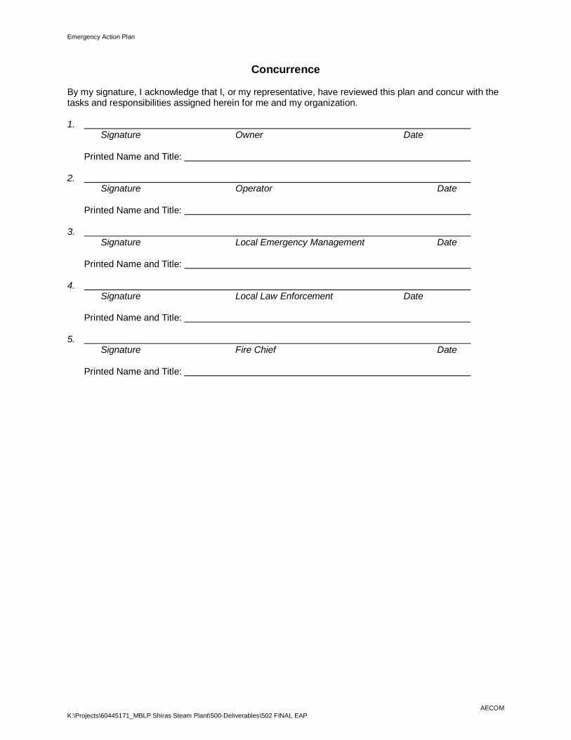
Concurrence
By my signature, I acknowledge that I, or my representative, have reviewed this plan and concur with thetasks and responsibilities assigned herein for me and my organization.
1. Signature Owner Date
Printed Name and Title:
2. Signature Operator Date
Printed Name and Title:
3. Signature Local Emergency Management Date
Printed Name and Title:
4. Signature Local Law Enforcement Date
Printed Name and Title:
5. Signature Fire Chief Date
Printed Name and Title:

Emergency Action Plan
K:\Projects\60445171_MBLP Shiras Steam Plant\500-Deliverables\502 FINAL EAPAECOM
Emergency Action Plan Updates
Rev # Date Sections Reviewed or Revisions Made Revisions Made By
1
2
3
4
5
6
7
8
9
10

Emergency Action Plan
K:\Projects\60445171_MBLP Shiras Steam Plant\500-Deliverables\502 FINAL EAPAECOM
List of Holders, Receipt Confirmation, and Emergency Action Plan Updates
# Name Address Telephone # Date of Receipt
1
2
3
4
5
6
7
8
9
10
Last Updated: April, 2017
Emergency Action Plan
K:\Projects\60445171_MBLP Shiras Steam Plant\500-Deliverables\502 FINAL EAPAECOM
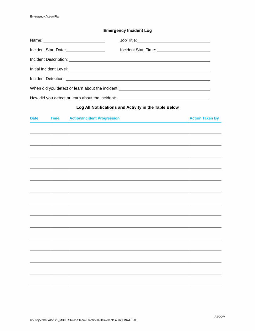
Emergency Incident Log
Name: Job Title:
Incident Start Date: Incident Start Time:
Incident Description:
Initial Incident Level:
Incident Detection:
When did you detect or learn about the incident:
How did you detect or learn about the incident:
Log All Notifications and Activity in the Table Below
Date Time Action/Incident Progression Action Taken By

Emergency Action Plan
K:\Projects\60445171_MBLP Shiras Steam Plant\500-Deliverables\502 FINAL EAPAECOM
Emergency Termination Log
Impoundment Name: County:
Impoundment Location: Stream/River:
Date/Time:
Weather Conditions:
General Description of Emergency Situation:
Area of Impoundment Affected:
Extent of Damage to Impoundment & Possible Cause:
Effect on Impoundment Operation:
Initial Reservoir Elevation/Time:
Maximum Reservoir Elevation/Time:
Final Reservoir Elevation/Time:
Description of Area Flooded Downstream / Damage/ Loss of Life:
Justification for Termination of Dam Safety Emergency:
Other Data and Comments:
Report Prepared By:(Printed Name and Signature) (Date)
Emergency Action Plan
K:\Projects\60445171_MBLP Shiras Steam Plant\500-Deliverables\502 FINAL EAPAECOM
Appendix D – GlossaryBreach: An opening through the embankment resulting in partial or total failure of the impoundment.
Consequences: Potential loss of life or property damage downstream of an impoundment caused byfloodwaters released at the impoundment or by waters released by partial or complete failure ofimpoundment. This includes effects of landslides upstream of the impoundment on the property locatedaround the reservoir.
Emergency Action Plan (EAP): Formal document that identifies potential emergency conditions at animpoundment and specifies preplanned actions to be followed to minimize property damage and loss oflife. The EAP describes actions the owner will take to moderate or alleviate a problem at theimpoundment, as well as actions the owner, in coordination with emergency management authorities, willtake to respond to incidents or emergencies related to the impoundment.
EAP exercise: Activity designed to promote prevention, preparedness, and response to incidents andemergencies, and may also be extended to include recovery operations. The exercise also demonstratesthe EAP’s effectiveness in an actual situation and demonstrates the readiness levels of key personnel.Periodic exercises result in an improved EAP because lessons learned are incorporated into the updatedEAP document. Exercises consist of testing and performing the duties, tasks, or operations identified anddefined within the EAP through a simulated event.
Emergency: Any incident, whether natural or manmade, that requires responsive action to protect life orproperty.
Emergency alert system: A federally established network of commercial radio stations that voluntarilyprovide official emergency instructions or directions to the public during an emergency.
Emergency management authority: State, local, Tribal, or Territorial agency responsible for emergencyoperations, planning, mitigation, preparedness, response, and recovery for all hazards. Names ofemergency management authorities vary (e.g., Division of Emergency Management, ComprehensiveEmergency Management, Disaster Emergency Services, Emergency and Disaster Services).
Emergency Operations Center: The location or facility where responsible officials gather during anemergency to direct and coordinate emergency operations, to communicate with other jurisdictions andwith field emergency forces, and to formulate protective action decisions and recommendations during anemergency.
Flood hydrograph: Graph showing the discharge, height, or other characteristic of a flood with respect totime for a given point on a stream.
Flood routing: Process of determining progressively, over time, the amplitude of a flood wave as itmoves past an impoundment or downstream to successive points along a river or stream.
Hazard potential: Situation that creates the potential for adverse consequences, such as loss of life,property damage, or other adverse impact. Impacts may be for a defined area downstream of animpoundment from floodwaters released through spillways and outlet works of the impoundment orwaters released by partial or complete failure of the impoundment. They may also be for an areaupstream of the impoundment from the effects of backwater flooding or the effects of landslides aroundthe reservoir perimeter.
Headwater: Water immediately upstream from an impoundment. The water surface elevation varies dueto fluctuations in inflow and the amount of water passed through the impoundment.
Incident: An incident in terms of impoundment operation includes an impending or actual sudden releaseof water caused by an accident to, or failure of, an impoundment or other water retaining structure, or theresult of an impending flood condition when the impoundment is not in danger of failure, or any condition
Emergency Action Plan
K:\Projects\60445171_MBLP Shiras Steam Plant\500-Deliverables\502 FINAL EAPAECOM
that may affect the safe operation of the impoundment. The release of water may or may not endangerhuman life, downstream property and structures, or facility operations.
Impoundment Failure: Catastrophic type of failure characterized by the sudden, rapid, and uncontrolledrelease of impounded water. There are lesser degrees of failure, but any malfunction or abnormalityoutside the design assumptions and parameters that adversely affect an impoundment’s primary functionof impounding water is properly considered a failure. Lesser degrees of failure can progressively lead toor heighten the risk of a catastrophic failure. They are, however, normally amendable to corrective action.
Inflow Design Flood (IDF): Flow used in the design of an impoundment and its appurtenant works,particularly for sizing the spillway and outlet works, and for determining the maximum height of theimpoundment, freeboard, and temporary storage requirements. The IDF is typically the flow above whichthe incremental increase in water surface elevation due to failure of an impoundment is no longerconsidered to present an unacceptable threat to downstream life or property. The upper limit of an IDF isthe Probable Maximum Flood.
Inundation map: Map delineating areas that would be flooded as a result of an impoundment failure.
Inundation zone: Area downstream of the impoundment that would be inundated by the released water.This zone is typically demarcated by a boundary reflecting the vertical elevation of the peak flow of waterfor both a flood failure and “sunny day” failure situation.
Notification: To inform appropriate individuals about an emergency condition so they can takeappropriate action.
Owner: Entity that owns the impoundment and associated facilities. The owner also includes the operatorand operating organization.
Probable Maximum Flood (PMF): Flood that may be expected from the most severe combination ofcritical meteorological and hydrologic conditions that is reasonably possible in the drainage basin understudy.
Tailwater: Water immediately downstream from an impoundment. The water surface elevation varies dueto fluctuations in the outflow from the structures of an impoundment. Tailwater monitoring is an importantconsideration because a failure of an impoundment will cause a rapid rise in the level of the tailwater.

Emergency Action Plan
K:\Projects\60445171_MBLP Shiras Steam Plant\500-Deliverables\502 FINAL EAPAECOM
aecom.com