emerson a0701pbu april 2017 a0701pbu emerson™ 701p ... refer to chapter 6 for disposal or...
TRANSCRIPT
Quick Start GuideMHM-97913-CC-PBF-EN, Rev 1
April 2017
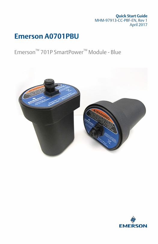
Emerson A0701PBU
Emerson™ 701P SmartPower™ Module - Blue
Copyright
© 2017 by Emerson. All rights reserved.
No part of this publication may be reproduced, transmitted, transcribed, stored in a retrievalsystem, or translated into any language in any form by any means without the written permissionof Emerson.
Disclaimer
This manual is provided for informational purposes. EMERSON MAKES NO WARRANTY OF ANYKIND WITH REGARD TO THIS MATERIAL, INCLUDING, BUT NOT LIMITED TO, THE IMPLIEDWARRANTIES OF MERCHANTABILITY AND FITNESS FOR A PARTICULAR PURPOSE. Emerson shallnot be liable for errors, omissions, or inconsistencies that may be contained herein or forincidental or consequential damages in connection with the furnishing, performance, or use ofthis material. Information in this document is subject to change without notice and does notrepresent a commitment on the part of Emerson. The information in this manual is not all-inclusive and cannot cover all unique situations.
Trademarks and Servicemarks
See http://www2.emersonprocess.com/siteadmincenter/PM Central Web Documents/marks.pdf
All other marks are property of their respective owners.
Patents
The product(s) described in this manual are covered under existing and pending patents.
ContentsDocument scope .......................................... 3
Label and date of manufacture ..................... 5
Warnings on product labels .......................... 6
Physical installation ...................................... 7
Verify Operation ........................................... 9
Disposal or recycling of depleted powermodules ..................................................... 12
Product certifications ..................................13
Quick Start Guide April 2017
2 MHM-97913-CC-PBF-EN, Rev 1

1 Document scope
NOTICE
This guide provides basic guidelines for the Blue Power Module (A0701PBU).It does not provide instructions for detailed configuration, diagnostics,maintenance, service, troubleshooting, or installation of wireless devices.Refer to the wireless device's manuals and Quick Start Guides for moreinstruction.
The Blue Power Module (referred to in this document as Model A0701PBU;Part Number MHM-89004) is an extended life power module has a broad fieldof application. It can be used to provide long-lasting power to many ofEmerson's wireless transmitters including models 3051S, 648, 702, 705,2160, and 9420. Use this guide to install or replace the power module in anyof these transmitters—they share the same enclosure, enclosure thread, andpower module connection mechanism.
The power module is designed for use in explosive gas atmospheresaccording to the marking assigned.
Because Emerson's SmartPower power modules are self-contained, there isno need for cables, cable glands, etc. during the installation process. Nospecific training is required beyond what is outlined in this document. Asalways, personnel should take care to consider any applicable local, nationalor international regulations that may apply.
These instructions are intended for qualified personnel with the necessarylevel of tolerance. Installation carried out only in accordance with nationalregulations of electrical installation in hazardous areas, including inaccordance with the standards GOST 30852.16-2002 GOST 30852.13-99GOST IEC 60079.14-2011.
April 2017 Quick Start Guide
MHM-97913-CC-PBF-EN, Rev 1 3
WARNING!
• Explosions could result in death or serious injury.
• Installation of this power module in an explosive environment must be inaccordance with the appropriate local, national, and internationalstandards, codes, and practices. Please review Product Certifications forany restrictions associated with a safe installation.
• Before connecting a Field Communicator in an explosive atmosphere,ensure the instruments are installed in accordance with intrinsically safeor non-incendive field wiring practices.
• Electrical shock can result in death or serious injury.
• Avoid contact with the leads and terminals. High voltage that may bepresent on leads can cause electrical shock. The power module may bereplaced in a hazardous area.
• The power module has surface resistivity greater than one gigaohm andmust be properly installed in the wireless device enclosure. Care must betaken during transportation to and from the point of installation toprevent electrostatic charge build-up. Under certain extremecircumstances, it could be possible to build up an ignition-capable level ofelectrostatic charge in the enclosure. Therefore, the equipment shouldnot be installed in a location where the external conditions are conduciveto the build-up of electrostatic charge on such surfaces. This isparticularly important if the equipment is installed in a Zone 0 location.
CAUTION!
Each Blue Power Module (A0701PBU) contains two "D" size primary lithiumbatteries. Primary lithium batteries are regulated in transportation by theU.S. Department of Transportation, and are also covered by IATA(International Air Transport Association), ICAO (International Civil AviationOrganization), and ARD (European Ground Transportation of DangerousGoods). It is the responsibility of the shipper to ensure compliance with theseor any other local requirements. Please consult current regulations andrequirements before shipping.
Quick Start Guide April 2017
4 MHM-97913-CC-PBF-EN, Rev 1
2 Label and date of manufacture
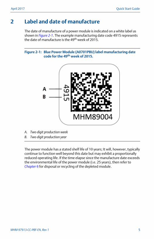
The date of manufacture of a power module is indicated on a white label asshown in Figure 2-1. The example manufacturing date code 4915 representsthe date of manufacture is the 49th week of 2015.
Blue Power Module (A0701PBU) label manufacturing datecode for the 49th week of 2015.
Figure 2-1:
A. Two digit production weekB. Two digit production year
The power module has a stated shelf life of 10 years; It will, however, typicallycontinue to function well beyond this date but may exhibit a proportionallyreduced operating life. If the time elapse since the manufacture date exceedsthe environmental life of the power module (i.e. 25 years), then refer to Chapter 6 for disposal or recycling of the depleted module.
April 2017 Quick Start Guide
MHM-97913-CC-PBF-EN, Rev 1 5
3 Warnings on product labels
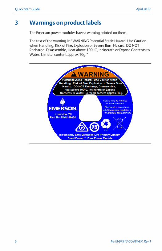
The Emerson power modules have a warning printed on them.
The text of the warning is: “WARNING Potential Static Hazard, Use Cautionwhen Handling. Risk of Fire, Explosion or Severe Burn Hazard. DO NOTRecharge, Disassemble, Heat above 100 °C, Incinerate or Expose Contents toWater. Li metal content approx 10g.”
Quick Start Guide April 2017
6 MHM-97913-CC-PBF-EN, Rev 1

4 Physical installation
The Blue Power Module (A0701PBU) has been designed with safety in mind.The connector is keyed so that it cannot be inserted incorrectly, and it uses apatented mechanism that enables it to be replaced while the transmitter isinstalled in a hazardous area. The installation procedure includes replacingthe power module and extended battery cover.
Prerequisites
When replacing a standard Black Power Module with the extended life BluePower Module, you also need to replace the smaller end cap (2.5 in / 70 mm)with the extended end cap (4.5 in / 115 mm).
Procedure
1. Inspect the power module for any obvious signs of damage.
Emerson's SmartPower Power Modules are designed to be rugged. Theproduct design has been tested in environmental conditions such asextreme temperature, pressure, vibration and shock. In testing, it alsowas dropped repeatedly from 3m height without leading to an unsafeoperating condition.
If there are any obvious signs of damage, do not install the powermodule. Refer to Chapter 6 for disposal or recycling of the power module.
2. Install the HART™ wireless device according to standard installationpractices and the manufacturer’s instructions, being sure to use anapproved thread sealant on all connections.
3. Unscrew the power module cover from the wireless device.
Normally, no tools are required; however, a strap wrench may be used tounscrew the cover.
4. Connect the power module to the wireless device. The power module hasa keyed connection to prevent improper connection.
April 2017 Quick Start Guide
MHM-97913-CC-PBF-EN, Rev 1 7

Blue Power Module (A0701PBU) connects using a keyedconnection on the wireless device
Figure 4-1:
NotePower up wireless devices in order of proximity from the EmersonWireless Gateway, beginning with the closest. This will result in a simplerand faster network installation.
5. Close the extended battery cover on the housing and tighten. Alwaysensure a proper seal by installing the electronics housing covers so thatmetal touches metal, but do not over tighten.
Quick Start Guide April 2017
8 MHM-97913-CC-PBF-EN, Rev 1

5 Verify Operation
Operation can be verified in four locations: by using the Field Communicator,at the Gateway via the Emerson Wireless Gateway’s integrated web server,via AMS Wireless Configurator, or with the wireless device’s LCD display.
Field Communicator
If you are able to communicate to the wireless device via a FieldCommunicator, the power module is powering the device and workingcorrectly. Figure 5-1 shows how to connect a Field Communicator to awireless device.
Field Communicator ConnectionsFigure 5-1:
Emerson Wireless Gateway
If the wireless device was configured with the Network ID and Join Key andsufficient time has passed for network polling, the transmitter will beconnected to the network. To verify device operation and connection to thenetwork with the Smart Wireless Gateway’s integrated web server, open theSmart Wireless Gateway’s integral web interface, and navigate to theExplorer page. If the wireless device has joined the network, the PowerModule is functioning properly.
NOTICE
It may take several minutes for the device to join the network.
April 2017 Quick Start Guide
MHM-97913-CC-PBF-EN, Rev 1 9
AMS Wireless Configurator
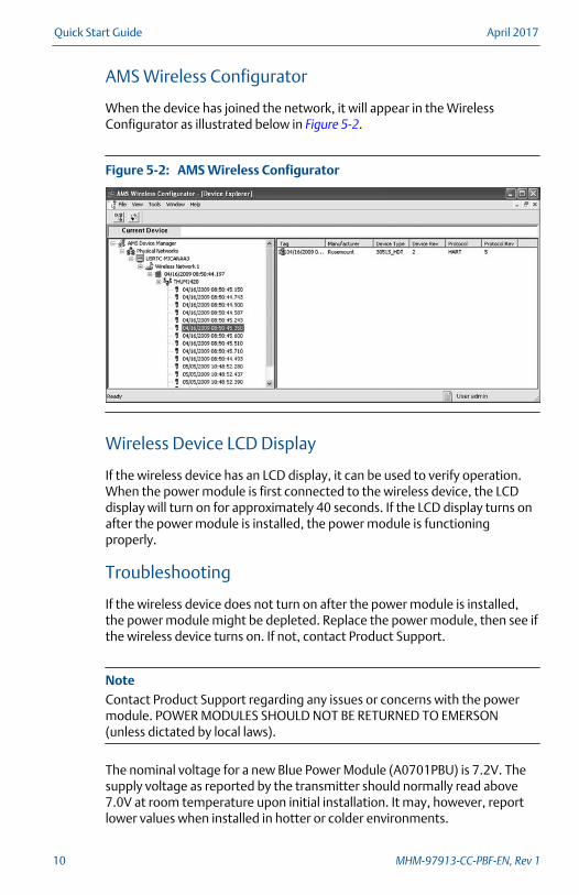
When the device has joined the network, it will appear in the WirelessConfigurator as illustrated below in Figure 5-2.
AMS Wireless ConfiguratorFigure 5-2:
Wireless Device LCD Display
If the wireless device has an LCD display, it can be used to verify operation.When the power module is first connected to the wireless device, the LCDdisplay will turn on for approximately 40 seconds. If the LCD display turns onafter the power module is installed, the power module is functioningproperly.
Troubleshooting
If the wireless device does not turn on after the power module is installed,the power module might be depleted. Replace the power module, then see ifthe wireless device turns on. If not, contact Product Support.
NoteContact Product Support regarding any issues or concerns with the powermodule. POWER MODULES SHOULD NOT BE RETURNED TO EMERSON(unless dictated by local laws).
The nominal voltage for a new Blue Power Module (A0701PBU) is 7.2V. Thesupply voltage as reported by the transmitter should normally read above7.0V at room temperature upon initial installation. It may, however, reportlower values when installed in hotter or colder environments.
Quick Start Guide April 2017
10 MHM-97913-CC-PBF-EN, Rev 1

Each Emerson transmitter has a unique minimum supply voltagerequirement for sustained operation. If the supply voltage drops below itsminimum supply voltage, the device will report the operational error bygenerating the alert message: "CRITICAL_POWER_FAILURE". When thisoccurs, the power module should be replaced as soon as possible. Refer to Chapter 6 for disposal or recycling of the depleted module.
April 2017 Quick Start Guide
MHM-97913-CC-PBF-EN, Rev 1 11
6 Disposal or recycling of depleted powermodules
1. Dispose in accordance with applicable laws and regulations in yourcountry and state.
2. Disposal should only be performed by authorized professionals inaccordance with applicable requirements for hazardous wastetransportation and disposal.
3. Incineration should only be performed by trained professionals inauthorized facilities.
Shipping regulations
Primary lithium batteries are regulated in transportation by the U.S.Department of Transportation and are also covered by IATA (International AirTransport Association), ICAO (International Civil Aviation Organization), andARD (European Ground Transportation of Dangerous Goods). It is theresponsibility of the shipper to ensure compliance with these or any otherlocal requirements. Please consult current regulations and requirementsbefore shipping.
Handling considerations
Each blue power module (A0701PBU) contains two “D” size primary lithiumbatteries. Under normal conditions, the battery materials are self-containedand are not reactive as long as the batteries and the battery pack integrity aremaintained. Care should be taken to prevent thermal, electrical, ormechanical damage. Contacts should be protected to prevent prematuredischarge. Use caution when handling the power module. It may bedamaged if dropped onto a hard surface. Battery hazards remain when cellsare discharged.
Environmental considerations
As with any battery, local environmental rules and regulations should beconsulted for proper management of spent batteries. If no specificrequirements exist, recycling through a qualified recycler is encouraged.Consult the materials safety data sheet for battery specific information.
Quick Start Guide April 2017
12 MHM-97913-CC-PBF-EN, Rev 1
7 Product certifications
European directive information
A copy of the EC Declaration of Conformity can be found at the end of theQuick Start Guide. The most recent revision of the EC Declaration ofConformity can be found at www.emerson.com.
ATEX directive (2014/34/EU)
Emerson Process Management complies with the ATEX Directive.
Electro Magnetic Compatibility (EMC) (2014/30/EU)
Emerson Process Management complies with the EMC Directive.
Ordinary location certification
The transmitter has been examined and tested to determine that the designmeets the basic electrical, mechanical, and fire protection requirements.
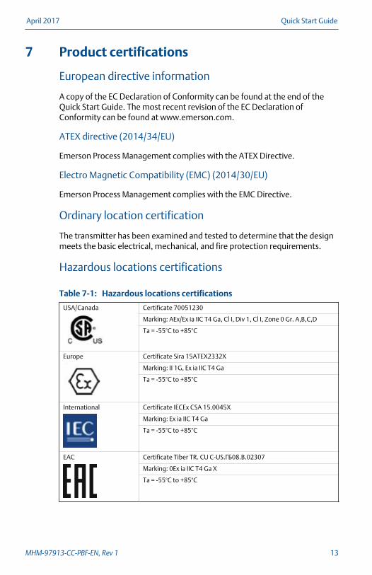
Hazardous locations certifications
Hazardous locations certificationsTable 7-1:
USA/Canada Certificate 70051230
Marking: AEx/Ex ia IIC T4 Ga, Cl I, Div 1, Cl I, Zone 0 Gr. A,B,C,D
Ta = -55°C to +85°C
Europe Certificate Sira 15ATEX2332X
Marking: II 1G, Ex ia IIC T4 Ga
Ta = -55°C to +85°C
International Certificate IECEx CSA 15.0045X
Marking: Ex ia IIC T4 Ga
Ta = -55°C to +85°C
EAC Certificate Tiber TR. CU C-US.ГБ08.B.02307
Marking: 0Ex ia IIC T4 Ga X
Ta = -55°C to +85°C
April 2017 Quick Start Guide
MHM-97913-CC-PBF-EN, Rev 1 13
Safety Parameters
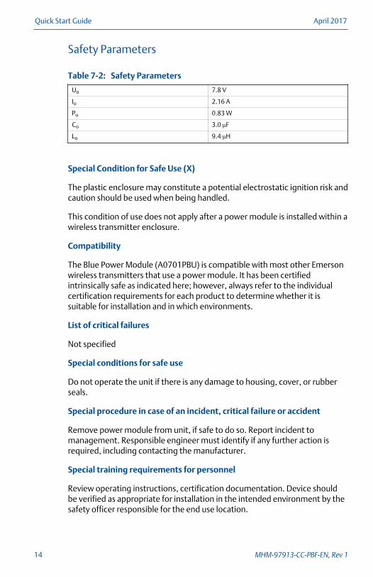
Safety ParametersTable 7-2:
Uo 7.8 V
Io 2.16 A
Po 0.83 W
Co 3.0 µF
Lo 9.4 µH
Special Condition for Safe Use (X)
The plastic enclosure may constitute a potential electrostatic ignition risk andcaution should be used when being handled.
This condition of use does not apply after a power module is installed within awireless transmitter enclosure.
Compatibility
The Blue Power Module (A0701PBU) is compatible with most other Emersonwireless transmitters that use a power module. It has been certifiedintrinsically safe as indicated here; however, always refer to the individualcertification requirements for each product to determine whether it issuitable for installation and in which environments.
List of critical failures
Not specified
Special conditions for safe use
Do not operate the unit if there is any damage to housing, cover, or rubberseals.
Special procedure in case of an incident, critical failure or accident
Remove power module from unit, if safe to do so. Report incident tomanagement. Responsible engineer must identify if any further action isrequired, including contacting the manufacturer.
Special training requirements for personnel
Review operating instructions, certification documentation. Device shouldbe verified as appropriate for installation in the intended environment by thesafety officer responsible for the end use location.
Quick Start Guide April 2017
14 MHM-97913-CC-PBF-EN, Rev 1

Shelf Life
10 years
NoteShelf life can be maximized by storing the power module in a dry locationwith an ambient temperature between 60 and 80 ⁰ F (16 to 26 ⁰ C).
Storage Temperature
-40 to +185⁰F (-40 to +85⁰C)
Service Life
Power module life is mainly a function of the wireless update rate. Fasterwireless update rates, as well as acquisition of specialized data such asvibration spectra and waveforms, will decrease power module life. Powermodule life is further affected by extreme temperature service and wirelessnetwork conditions.
April 2017 Quick Start Guide
MHM-97913-CC-PBF-EN, Rev 1 15

Declaration of Conformity
Quick Start Guide April 2017
16 MHM-97913-CC-PBF-EN, Rev 1

April 2017 Quick Start Guide
MHM-97913-CC-PBF-EN, Rev 1 17

Quick Start Guide April 2017
18 MHM-97913-CC-PBF-EN, Rev 1

April 2017 Quick Start Guide
MHM-97913-CC-PBF-EN, Rev 1 19

Quick Start GuideMHM-97913-CC-PBF-EN, rev. 1
April 2017
Emerson835 Innovation DriveKnoxville, TN 37932 USAT +1 865-675-2400F +1 865-218-1401www.Emerson.com
©2017, Emerson.All rights reserved. The Emerson logo is atrademark and service mark of Emerson Electric Co.All other marks are property of their respectiveowners.The contents of this publication are presented forinformational purposes only, and while every efforthas been made to ensure their accuracy, they arenot to be construed as warranties or guarantees,express or implied, regarding the products orservices described herein or their use orapplicability. All sales are governed by our termsand conditions, which are available on request. Wereserve the right to modify or improve the designsor specifications of our products at any timewithout notice.