emerson smart wireless field link - spartan controls/media/resources/rosemount/quick start... ·...
TRANSCRIPT
Quick Start Guide00825-0100-4421, Rev CA
June 2016
00825-0100-4421_RevCA.fm Page 1 Tuesday, June 21, 2016 5:16 PM
Emerson™ Smart Wireless Field Link
June 2016Quick Start Guide
00825-0100-4421_RevCA.fm Page 2 Tuesday, June 21, 2016 5:16 PM
NOTICEThis guide provides basic guidelines for the Smart Wireless Field Link. It does not provide instructions for diagnostics, maintenance, service, or troubleshooting. This guide is also available electronically on www.emersonprocess.com.
Failure to follow these installation guidelines could result in death or serious injury.
Make sure only qualified personnel perform the installation.
Explosions could result in death or serious injury.
Installation of this transmitter in an explosive environment must be in accordance with the appropriate local, national, and international standards, codes, and practices. Review the Product Certifications section for any restrictions associated with a safe installation.
Electrical shock can result in death or serious injury.
Avoid contact with the leads and terminals. High voltage may be present on leads can cause electrical shock.
This device complies with Part 15 of the FCC Rules. Operation is subject to the following conditions:
This device may not cause harmful interference.
This device must accept any interference received, including interference that may cause undesired operation.
This device must be installed to ensure a minimum antenna separation distance of 8-in. (20 cm) from all persons.
ContentsWireless considerations . . . . . . . . . . . . . . . . . . . 3Physical installation . . . . . . . . . . . . . . . . . . . . . . . 5Verify operation . . . . . . . . . . . . . . . . . . . . . . . . . . 6
Reference information . . . . . . . . . . . . . . . . . . 7Ordering information . . . . . . . . . . . . . . . . . . . . . 9Product Certifications . . . . . . . . . . . . . . . . . . . . 10
2
Quick Start GuideJune 2016
00825-0100-4421_RevCA.fm Page 3 Tuesday, June 21, 2016 5:16 PM
1.0 Wireless considerations
1.1 Power up sequenceThe Smart Wireless Field Link and wireless I/O should be installed and functioning properly before the power modules are installed in any wireless field devices. Wireless field devices should also be powered up in order of proximity from the Field Link beginning with the closest. This will result in a simpler and faster network installation.
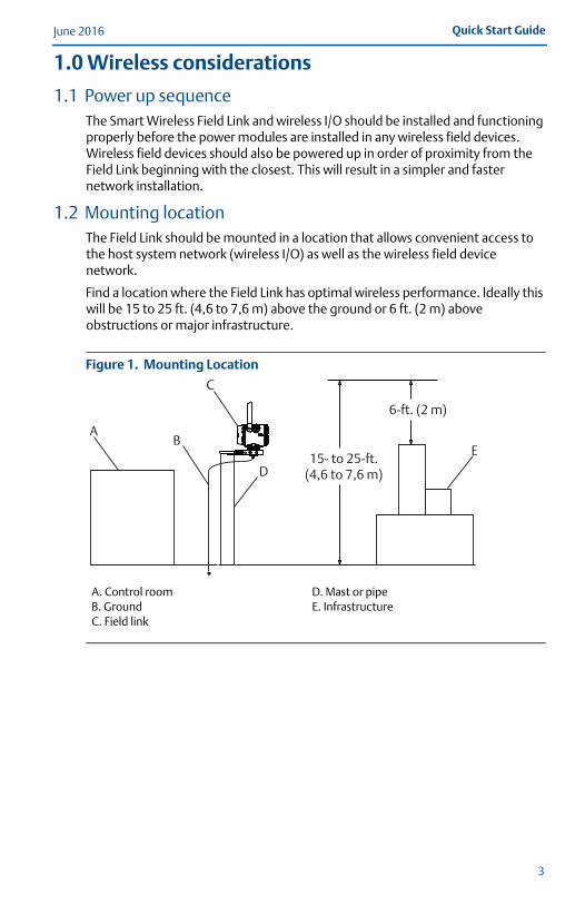
1.2 Mounting locationThe Field Link should be mounted in a location that allows convenient access to the host system network (wireless I/O) as well as the wireless field device network.
Find a location where the Field Link has optimal wireless performance. Ideally this will be 15 to 25 ft. (4,6 to 7,6 m) above the ground or 6 ft. (2 m) above obstructions or major infrastructure.
Figure 1. Mounting Location
A. Control roomB. GroundC. Field link
D. Mast or pipeE. Infrastructure
AB
C
D
E15- to 25-ft.
(4,6 to 7,6 m)
6-ft. (2 m)
3
June 2016Quick Start Guide
00825-0100-4421_RevCA.fm Page 4 Tuesday, June 21, 2016 5:16 PM
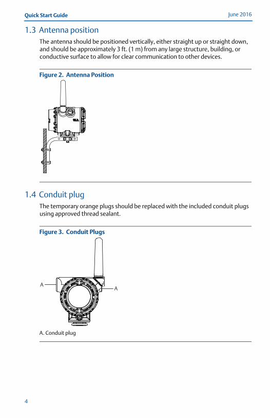
1.3 Antenna positionThe antenna should be positioned vertically, either straight up or straight down, and should be approximately 3 ft. (1 m) from any large structure, building, or conductive surface to allow for clear communication to other devices.
Figure 2. Antenna Position
1.4 Conduit plugThe temporary orange plugs should be replaced with the included conduit plugs using approved thread sealant.
Figure 3. Conduit Plugs
A. Conduit plug
AA
4

Quick Start GuideJune 2016
00825-0100-4421_RevCA.fm Page 5 Tuesday, June 21, 2016 5:16 PM
5
1.5 Intended useThe Field Link must be used in conjunction with a network manager or network Gateway. The Field Link then functions as a translator between the wired network and a wireless field network.
Figure 4. Example System Architecture
2.0 Physical installation
2.1 Pipe mounting1. Insert larger U-bolt around 2 in. pipe/mast, through the saddle, through the
L-shaped bracket, and through the washer plate.
2. Use a 1/2-in. socket-head wrench to fasten the nuts to the U-bolt.
3. Insert smaller U-bolt around base the Field Link and through the L-shaped bracket.
4. Use a 1/2-in. socket-head wrench to fasten the nuts to the U-bolt.
Figure 5. Mounting
A. Host systemB. Control networkC. Network manager
D. Field linkE. Wireless field networkF. Wireless field devices
A
B
C
D
E
F
June 2016Quick Start Guide
00825-0100-4421_RevCA.fm Page 6 Tuesday, June 21, 2016 5:16 PM
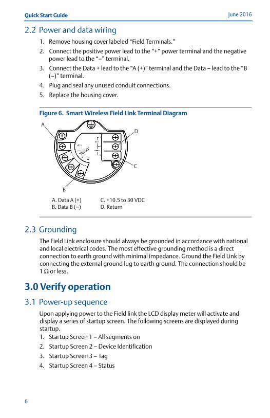
2.2 Power and data wiring1. Remove housing cover labeled “Field Terminals.”
2. Connect the positive power lead to the “+” power terminal and the negative power lead to the “–” terminal.
3. Connect the Data + lead to the “A (+)” terminal and the Data – lead to the “B (–)” terminal.
4. Plug and seal any unused conduit connections.
5. Replace the housing cover.
Figure 6. Smart Wireless Field Link Terminal Diagram
2.3 GroundingThe Field Link enclosure should always be grounded in accordance with national and local electrical codes. The most effective grounding method is a direct connection to earth ground with minimal impedance. Ground the Field Link by connecting the external ground lug to earth ground. The connection should be 1 Ω or less.
3.0 Verify operation
3.1 Power-up sequenceUpon applying power to the Field link the LCD display meter will activate and display a series of startup screen. The following screens are displayed during startup.1. Startup Screen 1 – All segments on
2. Startup Screen 2 – Device Identification
3. Startup Screen 3 – Tag
4. Startup Screen 4 – Status
A. Data A (+)B. Data B (–)
C. +10.5 to 30 VDCD. Return
A
B
C
D
6

Quick Start GuideJune 2016
00825-0100-4421_RevCA.fm Page 7 Tuesday, June 21, 2016 5:16 PM
3.2 Normal operationAfter the initial startup screens the Field Link will cycle through several periodic screens. 1. Electronics Temperature Screen
2. Percent Range Screen
3. Wired Interface Usage
4. Radio Interface Usage
The Field Link will continue to rotate through each periodic screen through the course of normal operation. If any diagnostic or fault condition occurs, a corresponding diagnostics screen will appear.
4.0 Reference information
Figure 7. Smart Wireless Field Link Terminal Diagram
NoteThe Smart Wireless Field Link requires separate twisted shield pairs (four wires) for power and data.
A. Data A (+)B. Data B (–)
C. +10.5 to 30 VDCD. Return
A
B
C
D
7
June 2016Quick Start Guide
00825-0100-4421_RevCA.fm Page 8 Tuesday, June 21, 2016 5:16 PM
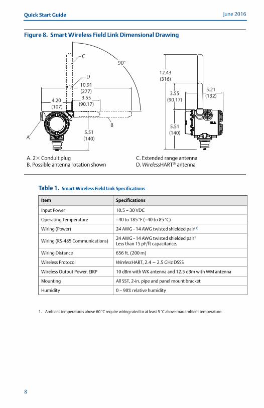
Figure 8. Smart Wireless Field Link Dimensional Drawing
Table 1. Smart Wireless Field Link Specifications
A. 2� Conduit plug B. Possible antenna rotation shown
C. Extended range antennaD. WirelessHART® antenna
Item Specifications
Input Power 10.5 – 30 VDC
Operating Temperature –40 to 185 °F (–40 to 85 °C)
Wiring (Power) 24 AWG - 14 AWG twisted shielded pair(1)
1. Ambient temperatures above 60 °C require wiring rated to at least 5 °C above max ambient temperature.
Wiring (RS-485 Communications) 24 AWG - 14 AWG twisted shielded pair1
Less than 15 pF/ft capacitance.
Wiring Distance 656 ft. (200 m)
Wireless Protocol WirelessHART, 2.4 – 2.5 GHz DSSS
Wireless Output Power, EIRP 10 dBm with WK antenna and 12.5 dBm with WM antenna
Mounting All SST, 2-in. pipe and panel mount bracket
Humidity 0 – 90% relative humidity
A
B
C
D
90°
5.51(140)
4.20 (107)
3.55(90.17)
10.91(277)
12.43(316)
3.55(90.17)
5.51(140)
5.21(132)
8
Quick Start GuideJune 2016
00825-0100-4421_RevCA.fm Page 9 Tuesday, June 21, 2016 5:16 PM
5.0 Ordering information
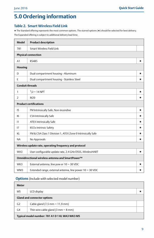
Table 2. Smart Wireless Field Link★ The Standard offering represents the most common options. The starred options (★) should be selected for best delivery.
The Expanded offering is subject to additional delivery lead time.
Model Product description
781 Smart Wireless Field Link
Physical connection
A1 RS485 ★
Housing
D Dual compartment housing - Aluminum ★
E Dual compartment housing - Stainless Steel ★
Conduit threads
1 1/2 – 14 NPT ★
2 M20 ★
Product certifications
I5 FM Intrinsically Safe, Non-incendive ★
I6 CSA Intrinsically Safe ★
I1 ATEX Intrinsically Safe ★
I7 IECEx Intrinsic Safety ★
KL FM & CSA Class 1 Division 1, ATEX Zone 0 Intrinsically Safe ★
NA No Approvals ★
Wireless update rate, operating frequency and protocol
WA3 User configurable update rate, 2.4 GHz DSSS, WirelessHART ★
Omnidirectional wireless antenna and SmartPower™
WK3 External antenna, line pow er 10 – 30 VDC ★
WM3 Extended range, external antenna, line power 10 – 30 VDC ★
Options (Include with selected model number)
Meter
M5 LCD display ★
Gland and connector options
G2 Cable gland (7,5 mm – 11,9 mm)
G4 Thin wire cable gland (3 mm – 8 mm)
Typical model number: 781 A1 D 1 KL WA3 WK3 M5
9
June 2016Quick Start Guide
00825-0100-4421_RevCA.fm Page 10 Tuesday, June 21, 2016 5:16 PM
6.0 Product CertificationsRev 1.1
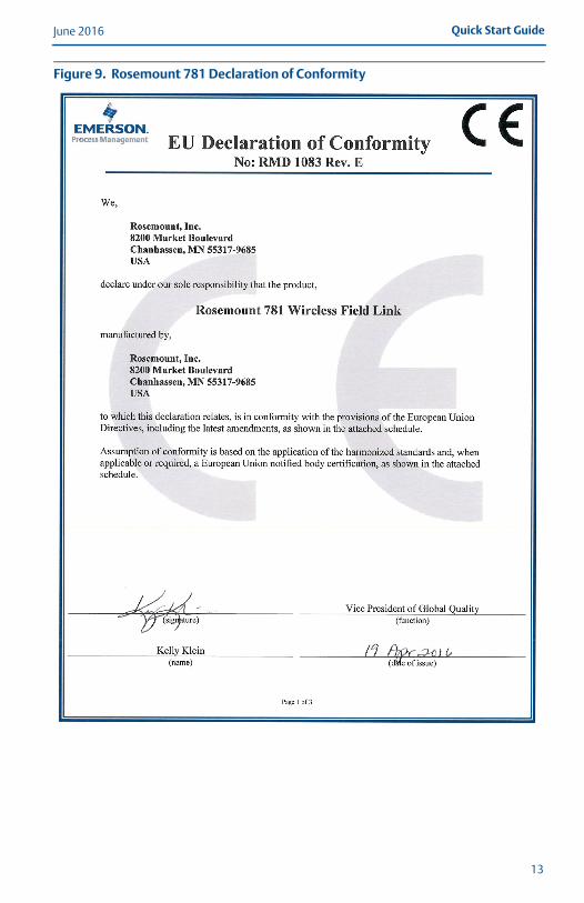
6.1 European Directive InformationA copy of the EC Declaration of Conformity can be found at the end of the Quick Start Guide. The most recent revision of the EC Declaration of Conformity can be found at www.rosemount.com.
6.2 Ordinary Location CertificationAs standard, the transmitter has been examined and tested to determine the design meets the basic electrical, mechanical, and fire protection requirements by a nationally recognized test laboratory (NRTL) as accredited by the Federal Occupational Safety and Health Administration (OSHA).
6.3 Installing in North AmericaThe US National Electrical Code (NEC) and the Canadian Electrical Code (CEC) permit the use of Division marked equipment in Zones and Zone marked equipment in Divisions. The markings must be suitable for the area classification, gas, and temperature class. This information is clearly defined in the respective codes.
USA
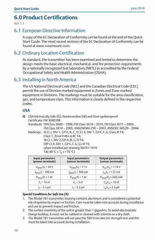
I5 USA Intrinsically Safe (IS), Nonincendive (NI) and Dust-ignitionproofCertificate: FM 3040398Standards: FM Class 3600 – 1998, FM Class 3610 – 2010, FM Class 3611 – 2004,
FM Class 3810 – 2005, ANSI/NEMA 250 – 2003, ANSI/IEC 60529 – 2004;Markings: IS CL I, DIV 1, GP A, B, C, D; CL II, DIV 1, GP E, F, G; Class III T4;
Class 1, Zone 0 AEx ia IIC T4;NI CL I, DIV 2, GP A, B, C, D T4;DIP CL II, DIV 1, GP E, F, G; CL III T4;when installed per drawing 00781-1010T4(-40 °C ≤ Ta ≤ +70 °C)
Special Conditions for Safe Use (X):1. The Model 781 transmitter housing contains aluminum and is considered a potential
risk of ignition by impact or friction. Care must be taken into account during installation and use to prevent impact and friction.
2. The surface resistivity of the unit is greater than 1 gigaohm. To avoid electrostatic charge buildup, it must not be rubbed or cleaned with solvents or a dry cloth.
3. The Model 781 transmitter will not pass the 500 Vrms electric strength test and this must be taken into account during installation.
Input parameters (power terminals)
Input parameters (sensor terminals)
Output parameters (sensor terminals)
VMAX/Ui = 30 V VMAX/Ui = 11 V Voc/Uo = 7.14 V
IMAX/Ii = 200 mA IMAX/Ii = 300 mA Isc/Io = 112 mA
PMAX/Pi = 1 W PMAX/Pi = 1 W PMAX/Po = 640 mW
Ci = 10 nF Ci = 5 nF Ca/Co = 10 nF
Li = 3.3 μH Li = 2.2 μH La/Lo= 3.3 μH
10
Quick Start GuideJune 2016
00825-0100-4421_RevCA.fm Page 11 Tuesday, June 21, 2016 5:16 PM
11
Canada
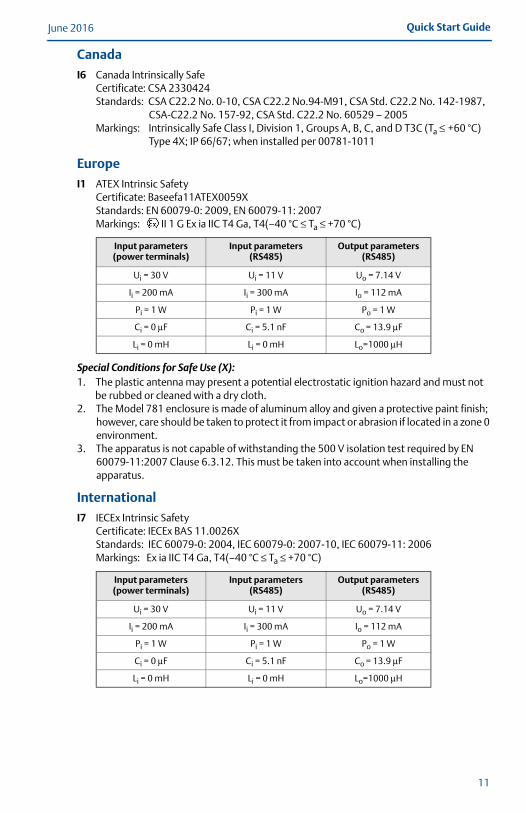
I6 Canada Intrinsically SafeCertificate: CSA 2330424Standards: CSA C22.2 No. 0-10, CSA C22.2 No.94-M91, CSA Std. C22.2 No. 142-1987,
CSA-C22.2 No. 157-92, CSA Std. C22.2 No. 60529 – 2005Markings: Intrinsically Safe Class I, Division 1, Groups A, B, C, and D T3C (Ta ≤ +60 °C)
Type 4X; IP 66/67; when installed per 00781-1011
Europe
I1 ATEX Intrinsic SafetyCertificate: Baseefa11ATEX0059XStandards: EN 60079-0: 2009, EN 60079-11: 2007Markings: II 1 G Ex ia IIC T4 Ga, T4(–40 °C ≤ Ta ≤ +70 °C)
Special Conditions for Safe Use (X):1. The plastic antenna may present a potential electrostatic ignition hazard and must not
be rubbed or cleaned with a dry cloth.2. The Model 781 enclosure is made of aluminum alloy and given a protective paint finish;
however, care should be taken to protect it from impact or abrasion if located in a zone 0 environment.
3. The apparatus is not capable of withstanding the 500 V isolation test required by EN 60079-11:2007 Clause 6.3.12. This must be taken into account when installing the apparatus.
International
I7 IECEx Intrinsic SafetyCertificate: IECEx BAS 11.0026XStandards: IEC 60079-0: 2004, IEC 60079-0: 2007-10, IEC 60079-11: 2006Markings: Ex ia IIC T4 Ga, T4(–40 °C ≤ Ta ≤ +70 °C)
Input parameters (power terminals)
Input parameters (RS485)
Output parameters (RS485)
Ui = 30 V Ui = 11 V Uo = 7.14 V
Ii = 200 mA Ii = 300 mA Io = 112 mA
Pi = 1 W Pi = 1 W Po = 1 W
Ci = 0 μF Ci = 5.1 nF Co = 13.9 μF
Li = 0 mH Li = 0 mH Lo=1000 μH
Input parameters (power terminals)
Input parameters (RS485)
Output parameters (RS485)
Ui = 30 V Ui = 11 V Uo = 7.14 V
Ii = 200 mA Ii = 300 mA Io = 112 mA
Pi = 1 W Pi = 1 W Po = 1 W
Ci = 0 μF Ci = 5.1 nF Co = 13.9 μF
Li = 0 mH Li = 0 mH Lo=1000 μH
June 2016Quick Start Guide
00825-0100-4421_RevCA.fm Page 12 Tuesday, June 21, 2016 5:16 PM
12
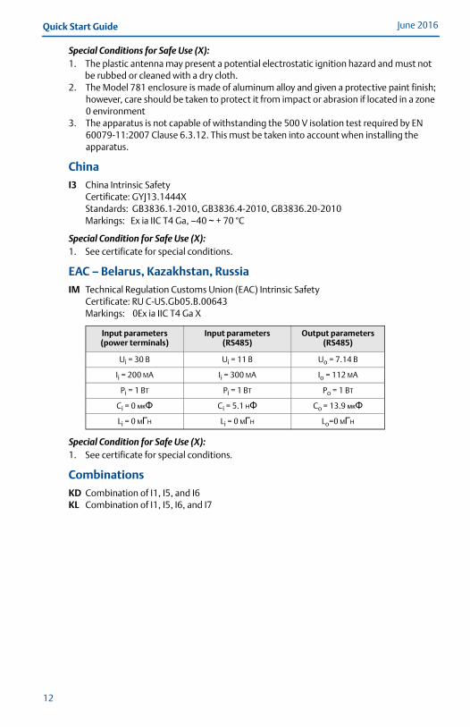
Special Conditions for Safe Use (X):1. The plastic antenna may present a potential electrostatic ignition hazard and must not
be rubbed or cleaned with a dry cloth.2. The Model 781 enclosure is made of aluminum alloy and given a protective paint finish;
however, care should be taken to protect it from impact or abrasion if located in a zone 0 environment
3. The apparatus is not capable of withstanding the 500 V isolation test required by EN 60079-11:2007 Clause 6.3.12. This must be taken into account when installing the apparatus.
China
I3 China Intrinsic SafetyCertificate: GYJ13.1444XStandards: GB3836.1-2010, GB3836.4-2010, GB3836.20-2010Markings: Ex ia IIC T4 Ga, –40 ~ + 70 °C
Special Condition for Safe Use (X):1. See certificate for special conditions.
EAC – Belarus, Kazakhstan, Russia
IM Technical Regulation Customs Union (EAC) Intrinsic SafetyCertificate: RU C-US.Gb05.B.00643Markings: 0Ex ia IIC T4 Ga X
Special Condition for Safe Use (X):1. See certificate for special conditions.
Combinations
KD Combination of I1, I5, and I6KL Combination of I1, I5, I6, and I7
Input parameters (power terminals)
Input parameters (RS485)
Output parameters (RS485)
Ui = 30 B Ui = 11 B Uo = 7.14 B
Ii = 200 MA Ii = 300 MA Io = 112 MA
Pi = 1 BT Pi = 1 BT Po = 1 BT
Ci = 0 мкΦ Ci = 5.1 HΦ Co = 13.9 мкΦLi = 0 MГH Li = 0 MГH Lo=0 MГH
Quick Start GuideJune 2016
00825-0100-4421_RevCA.fm Page 13 Tuesday, June 21, 2016 5:16 PM
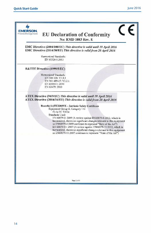
Figure 9. Rosemount 781 Declaration of Conformity
13
June 2016Quick Start Guide
00825-0100-4421_RevCA.fm Page 14 Tuesday, June 21, 2016 5:16 PM
14
Quick Start GuideJune 2016
00825-0100-4421_RevCA.fm Page 15 Tuesday, June 21, 2016 5:16 PM
15
June 2016Quick Start Guide
00825-0100-4421_RevCA.fm Page 16 Tuesday, June 21, 2016 5:16 PM
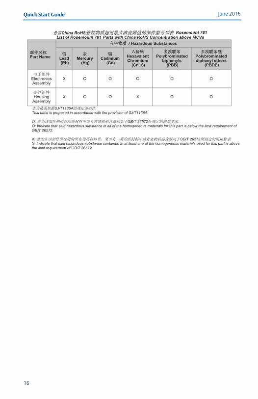
China RoHS
List of Rosemount 781
Rosemount 781 Parts with China RoHS Concentration above MCVs
Part Name
/ Hazardous Substances
Lead (Pb)
Mercury (Hg)
Cadmium (Cd)
Hexavalent Chromium
(Cr +6)
Polybrominated biphenyls
(PBB)
Polybrominated diphenyl ethers
(PBDE)
Electronics Assembly
X O O O O O
Housing Assembly
X O O X O O
SJ/T11364This table is proposed in accordance with the provision of SJ/T11364. O: GB/T 26572 O: Indicate that said hazardous substance in all of the homogeneous materials for this part is below the limit requirement of GB/T 26572. X: GB/T 26572 X: Indicate that said hazardous substance contained in at least one of the homogeneous materials used for this part is above the limit requirement of GB/T 26572.
16

Quick Start GuideJune 2016
00825-0100-4421_RevCA.fm Page 17 Tuesday, June 21, 2016 5:16 PM
17

00825-0100-4421_RevCA.fm Page 18 Tuesday, June 21, 2016 5:16 PM
Global HeadquartersEmerson Process Management 6021 Innovation Blvd.Shakopee, MN 55379, USA
+1 800 999 9307 or +1 952 906 8888+1 952 949 7001 [email protected]
North America Regional OfficeEmerson Process Management 8200 Market Blvd.Chanhassen, MN 55317, USA
+1 800 999 9307 or +1 952 906 8888
+1 952 949 7001
Latin America Regional OfficeEmerson Process Management 1300 Concord Terrace, Suite 400Sunrise, FL 33323, USA
+1 954 846 5030
+1 954 846 5121
[email protected] Linkedin.com/company/Emerson-Process-Management
Twitter.com/Rosemount_News
Facebook.com/Rosemount
Youtube.com/user/RosemountMeasurement
Google.com/+RosemountMeasurement
Standard Terms and Conditions of Sale can be found at www.Emerson.com/en-us/pages/Terms-of-Use.aspxThe Emerson logo is a trademark and service mark of Emerson Electric Co.SmartPower, Rosemount, and Rosemount logotype are trademarks of Emerson Process Management.WirelessHART is a registered trademark of the FieldComm Group.All other marks are the property of their respective owners.© 2016 Emerson Process Management. All rights reserved.
Europe Regional OfficeEmerson Process Management Europe GmbHNeuhofstrasse 19a P.O. Box 1046CH 6340 BaarSwitzerland
+41 (0) 41 768 6111
+41 (0) 41 768 6300
Asia Pacific Regional OfficeEmerson Process Management Asia Pacific Pte Ltd1 Pandan CrescentSingapore 128461
+65 6777 8211
+65 6777 0947 [email protected]
Middle East and Africa Regional OfficeEmerson Process Management Emerson FZE P.O. Box 17033,Jebel Ali Free Zone - South 2Dubai, United Arab Emirates
+971 4 8118100
+971 4 [email protected]
Quick Start Guide00825-0100-4421, Rev CA
June 2016
*00825-0100-4421*