e.m.i. advance all-waver - world radio history
TRANSCRIPT

ON THE THRESHOLD OF AMAZING DEVELOPMENTS
BAIRD AND E.M.I.
COMING TRANSMISSIONS
Official Details and
Simple Explanation
ADVANCE ALL-WAVER
Amateum, Ships, 'Plcmes, Wodd Broadcasters
16-2000 Metres all Visuallytuned. . A.C./D.C.
, Single Aero Dial. A.V.C.
Complete 1936 8-valve SUPer
) ;-
MONTHLY ft NOVEMBER, 1935.
No. tl. Vol. "111.
BIRNARD JONES PUBLICATIONS LTD.. CHANSITOR HOUSE. CHANCERY LANE,
LONDON, W.C:Z..

·r.e~Yl~JON AND
SHORT-WAVE WORLD
Cried a wireless-mechanic named Lane, "These sold' ring jobs give me a pain I" His Dad said-" My son Use FLUXITE, with the GUN. And you'll never have trouble again I "
See that FLUXITE Is alwayo by you-In the house-garace-workohop-wherever speedy soldering is needed, Used for 30 year• In •overnment works and by leading enaineers and manufacturera. Of Ironmongers-in tins, 4~ •• Bd., 1/4 and 1/8. Ask to oee the FLUXITE SMALL-SPACE SOLDERING SETcompact but substantial-complete with full lnotructlons, 7/6. Write for Free Book on the art of 11 soft" solderinl' and ask for Leaflet on CASE-HARDENING, STEEL and TEMPERING TOOLS
with FLUXITE
TO CYCLISTS ! Your wheels will NOT keep round and true unless the spokes are tied with fine wire at the crossings and SOLDERED. This makes a much atronger wheel. lt's simple-with FLUXITE-but IMPORTANT
THE FLUKITE GUN h alwayo ready to put fluxite on the ooldering job lnotantly. A little preuure places the· right quantity on the right opot and one charain1 lasts for aae•
Pri~e 1/6.
ALL MECHANICS
FLUXITE IT SIMPLIFIES ALL SOLDERING FLUXITE LTD. (Dept. T.V.), DRAGON WORKS, BERMONDSEY ST., S.E.l.
NEW BOOKLETS
I I \
·~~
Mention of u Television and Short-wave World ,. will ensure pr~mpt attention.
ii
NOVEMBER, 1935
········ ······
······ ··········
······ I I I I
.......... I

·r ~~YJSJOtJ NOVEMBER, 1935
AND SHORT-WAVE WORLD
LIST No. C.52 & 53.
Bulg~n 4 range SuperhetlJ7j6 Tumng Cml ... . .. Buhrin Oscillator Coil ... pr.pair
IN THIS ISSUE
e ADVANCE ALL-WAVE SUPERHET List No. C.SL Bulgin 4range SuperhetTun·l17J6 List No. S.IIS. Bulgin Double Pole On-Off 2/6
tng Cotl. . . . . . . . . . . . . . .. J Swttch . . . . . . . .. . . . each List No. C.53. Bulgin Oscillator Coil. pair.
List No. C.50 Bulgin Intermediate F re~ quency H.F. Transformer ... each 8/0
List No. S. 112. Bulgin Multi-Switch 8/0 each
List No. C.51. Bulgin Variable Selectivity 9/6 List No. V.T.50. Bulgin Magnetic Visual 7J6 I.F. Transformer . . . each Tuning Meter .. . . . . . . . each
List No. M.R.48. Bulgin Skeleton D.C. and 3/6 List No. K.12. Bulgin Moulded Walnut 41d A.C./D.C. Mains Resistances ... each Knob ... ... ··· ··· each 2 •
LIST No. C.Sl.
BULGil\l QUALITY RADIO COMPONENTS
,--·--·----------------couPoN------------------Piease despatch post free the new 100 page Catalo~ue and Manual No. 155 "M"
I enclose 3d. in stamps. Bulgin Variable Selectivity
l.F.Translormer. 9/6 each. NAME ......................................................... .< •••••••••••••••••••••••••••••••••••••••
ADDRESS ......................................................................................... .
A. LGIN, LTD., Abbey Road, Barking, Essex. Telephone: Grang;w"7.;;d"-n66-&n67------------------;;;;;;;;;;iTs;;;:;
A
·- -----------------------
EVERY ASPECT OF METAL RECTIFICATION
AS APPLIED TO RADIO is dealt with in "The All Metal Way, 1936." Contents include descriptions of the operation of Westinghouse Metal Rectifiers and Westectors, A.C. and Universal Mains Radio, Trickle
Charging of H.T. and LT. Batteries, Energising Moving-Coil Speakers, the use of Westectors for Distortionless Detection, A.V.C. and Battery Economising Circuits, etc., etc.
Metal Rectifiers for High Voltages and for Cathode-Ray operation
are also described.
Send the coupon for your copy to-day, enclosing 3d. stamps.
r--------------------------------l I COUPON. I I Westinghouse Brake & Signal Co., Ltd., j I 82, York Road, King's Cross, London, N.l. J 1 Plase send me a copy of" The All Metal Way, 1936" for which J I
I enclose 3d. in stamps. I I I 1 Name ................................................................................. 1
l_~~e~::_:::.::~::.:_·:.:_·:.:_·:.:_·:.:_·.:_::.:_::.:_::.:_::.:_:·:.::_:.:_::;_::.:_:~:::_::.:_::.:_:.·:.::_:.:_::.:_::.:_·.:J Better service results from mentioning u Television and Short-wave World" when writing to advertisers.
625

·r!!~'IJSJOl'J AND
SHORT-WAVE WORLD
The Solon Electric Soldering Iron has the strongest heating element obtainable. Clamped in contact with the bit, it concentrates all heat. None is wasted. The Solon simplifies soldering. lt is quicker, easier, more economical and more efficient. Plug in-solder in three minutes.
W. T. Henley's Telegraph Works Co. Ltd. Dept. 2.5. YAB. Holborn Viaduct, London,IE.C.I
SPECIFIED for the >c( 0 • ADVANCE ALL-WAVE 6 t-
SUPERHET The Wearite H.F.P.J.
:z 0 0... :l 0 u
Screened H.F. Choke. A compact and small dimen-
;;:i-...:siol~ed fully screened choke with an effective impedance range~ of I 00-2000 metres. Inductance 7 mmfd. D.C. resistance 770 ohms.
Price 2/·
"' :I:. • PRE-AMPLIFIER t- The Wearite Heavy Lever t- Switch Type 1.1. (I) A special low inter-contact capacity 2-way
0 switch of sturdy construction. Price5j6 (also made up to 5-way).
a. --~.-~----~-.a:-.a-=-~&--..IIIIQ.-:11-- ••. 'Ql ... ~ \I To I V WRIGHT & WEAl RE Ltd., I c 0 u P 0 N 740, High Rd. Tottenham,
I Pl~sesendmeacopy N.7. t1f Catalogue T.tG4to
J ðer with construe- Name ·
J ~~~~~. ef(~.~~~~~Ve~~t:; (L.P.) series of r~::- Address .................................... .
J ~=~~:;·sC~i~sN:~:·ll~~~ I N ~,\V . Shor_t-\V_ave ................................................ .
1 Coils (wtth circuits). T, 1 1.35 I I -----~~---~-~~~~~~.-s ~ 7731
626
NOVEMBER, 1935
• Type 4SjMT Mains transformer Price 8Sj-. e Type 4SjOP Output transformer (standard output 10,
20, 40 and 80 ohms). Price 4Sj-. Higher impedances. Price SO/-.
e Type 4S/IV lntervalve transformer. Price 3Sj-.
e Type 4S/F Filter choke. Price 19/-.
e Type 4S/S Smoothing choke. Price 22/-. e Type 4S/C Anode Coupling choke. Price 19/-. e Type CC38 Secondary Smoothing choke. Price 11/-.
Note.-With the exception cf the last item all these components have been specially designed by W. Bryan Savage, in collaboration with Kenneth Jowers, Short Wave Editor of Television, for this new amplifier. The designs are critical and results cannot be guaranteed except with these components.
For the convenience of customers, building the new amplifier, limited stocks of Dubilier 10 mfd., 750 v. D.C. working, oil-filled condensers are now held. The price is 17/-.
vv B R y A N
SAVAGE LIMITED.
S6a, CLERKENWELL ROAD, LONDON, E.C.I. Phone--Cierkenwell 3068.

No. 93 VOL. VIII NOVEMBER, 1935.
---------- ------- ---------
[and SHORT-WAVE WORLD Special Features
!'AGE Demonstration of the Farnsworth
System ... 628 Kerr Cell Light Valve ... 629 High-definition Transmission from
Alexandra Palace . . . . . . 631 Simple Explanation of the Official
Specifications 635 Tlw Advance All-waver ... 637 The Short-wave Radio \Vorld . . . 640 Kerr Cell Design for 240-line Operation 642 A Novel Scanning Circuit 643 Scanning Circuit Troubles 644 A Smooth d.c. Supply Unit .. . 645 Television in the Cinema 647 Recent Developments 649 A Pre-amplifier foc· tlw Short-wave
Receiver 654 The Alexandra Pabce . . . 656 The Goldmark Electron-optical System 661 Short-wave Entertainment 665 Optimum Performance from the Trans-
mitting Antenna 667 What Amateurs are D(,ing 669 The Design of High-definition Ampli-
fiers 672 45-Watt Low-loading Amplifier 676 Experimental s-metre Super ... 68o
TELEVISION AND
SHORT-WAVE WORLD Proprietors :
BERNARD ]ONES PuBLICATIONS, LTD.
Editor-in-Chief : BERNARD E. }ONES.
Editor: H. CORBISHLEY.
Editorial, Advertising and Publishing Offices:
Chansitor House, 38, Chancery Lane, London, w.c.2.
Telephones : Holbom 6158, 6159 Telegrams : Beejapee, Holb., London. Subscription Rates : Post paid to any part of the world--3 months, 3/6 ;
6 months, 6/g; 12 months, 13/6. Published Monthly-r/- net.
(Last Wednesday in every month for following month).
Contnbutions are invited and will be prompdy considered. Correspondence should be addressed according to its nature, to the Editor, the Advertisement Manager, or the Publisher, " Television and Short-wave World," Chansitor House, Chancery Lane, London, W.C.2.
IMPORTANT "Television and Short-wave World" is registilTed at the General Post Office, London,/or transmission to Canada and Newfoundland
by Magazine Post.
COMMENT OF THE MONTH
A Use for 30-line Gear.
AN interesting suggestion is made by a correspondf'nt on another page of this issue relating to the use of existing y•-line apparatus. The
sudden decision of the B.B.C. to discontinue these transmissions left a great number of people with apparatus on their hands which apparently immediately became useless; the B. B. C. absolves itself from any responsibility in the matter by its previous repeated reiterations that the service was experimental and liable to be discontinued at any time, an attitude which certainly did prevent a large number of people purchasing apparatus and at the same time limited the use of the service.
However, as our correspondent points out, there is still a very definite use for this gear for those who wish to become au fait with the many problems that will present them<>elves when the high-definition transmissions become a fact. His sug·ge<>tion is to convert existing receivers into simple transmitters and experiment in amplifier 'lesign, etc.; but there are many more sides to the matter which will occur to the ingenious experimenter. Among these are Kerr cell and light modulation experiments, and by modification of disc or drum, interlacing and other scanning variations can be considered. Also it should not be forgotten that modulation can be obtained on any sound programme and illumination intensities, etc., can be studied. Recorded programmes are also available. After all it was from this simple apparatus that the present possibilities were evolved, and so despite the fact that there are no programmes available it still has many potentialities for the keen experimenter.
Tbe Alexandra Palace
W E ask for your congratulations this month in being able to
present you with what we think will prove a reasonably accurate forecast of the arrangements at Alexandra Palace. Our pictorial layout is the first of its kind published anywhere and while it lacks the endorsement of the magic word '' official,'' we believe readers can accept our pictures as giving them a good working idea of v.:hat the Alexandra Palace transmitting station will look like when completed early next spring. A lot of hard work and the collation of details from many sources have gone to the making of our pictures.
627
Tbe Official Specifications
T HOUGH manufacturers and would-be manufacturers of
high-definition receivers are now in possession of the official data to allmv of the design of apparatus they have no means of carrying out practical tests. It looks therefore as if \vhen the transmissions are ready there. will be practically no receivers available and that the first fe\v month'i \Yill be a period of feverish activity. It is difficult to see any way out of this impasse at the present time, but it appears to be a problem which should have been foreseen by the Advisory Committee and some plans made for test transmissions to be put out.

·r.eLE'JJ~lON AND
SHORTcWAVE WORLD
A DEMONSTRATION OF
THE FARNSWORTH 20-KILOWATT, 7-METRE
NOVEMBER, 1935
SYSTEM TRANSMITTER PLANNED
For the following information on the latest developments of the Farnsworth system we are indebted to ELECTRONICS, the journal published by the McGraw Hill Company of New York.
R ECENTLY, Philo T. Farns,,·orth, of FarnS\YOrth Televtston, Inc., of Philadelphia, de
monstrated to the press the latest advances in his system of television. The demonstrati~m consisted of a half-hour programme of film and direct pick-up subjects, consisting of Mickey Mou~e cartoons, sections of
and a very large cathode-ray tube ( q ins. in diameter).
The fluorescent coating· on this large tube consisted of compounds of calcium, zinc. chlorine, tungsten and silicon, and produced a brilliant image in black and \Yhite, "·ith a verv faint pinkish cast. The pictures· \yere sent at a rate of 2-J. complete images
A photograph of the Farnsu'Orth studio shou·ing the latest elertronir scanner in use.
musical comedv and, for the direct pick-up, an on~hestra and vaudeville performance.
Transmission was accomplished by two means: "·ire and radio. The wire transmission was sent over a short \Yire circuit having a frequency band \Yidth of approximately t\HJ megacycles, \\'bile the radio \\'as sent from a I .)-\\'att transmitter on approximately 40 megacycles over a distance of about so ft., to a standard receiver mounted in a console.
A 14~in. Cathode~ray Tube
This latter receiver contained both sound and sight equipment with a conventional 7-in. cathode-ray tube for producing the image. The receiving end of the wire line transmission consisted of a special receiver
per second, interlaced t\\·o-to-one, i.e., a scanning frequency of -J-8 per second. The picture \\·as transmitted at 240 lines.
The result or the demonstration convinced the observers that a considerable improvement has been made during the past year by Mr. Farns\Yorth in his apparatus. The film pick-up, particularly, \\·as of a very high order of excellence, and was equal to the average home-movie m detail, brilliance and contrast.
Three Stations Planned
In announcing his plans for the futurP, Mr. Farns\\'orth revealed that he has undertaken to build three televtston transmitters. The first, which is no\\· under construction in San Francisco, has a po\\·er of ro kW.,
628
which mav eventuallv be increased to 20 k \V. . :\ 20-k W . station is to be installed in the laboratory ot the Farnsworth Company, in Chestnut Hill, Philadelphia, and a third transmitter will be installed later in New York City. These transmitters are of unusual design, in that they make use of the Farnsworth multipactor tube, a cold cathode electron multiplier (see TELEVISIO:\ AND SHORTWAVE \VoRLD, May, 1935). According to Mr. Farnsworth, a single tube of this type is capable of delivering an output of IO k \V of useful energy in the ultra-high frequency range, and a water-cooled type of this tube is now in development for this purpose. T\vo tubes operating in push-pull ,,-i 11 supply 20 k \\' output fo1· the proposed transmitters.
,\ master-oscillator power-amplifier type of transmitter is to be used. The oscillator is a small electron multiplier tube operating at approximately 20 megacycles, which is follo\\·ed by a fre<juency doubler stage and a final amplifier. Modulation \\'ill be applied to the final amplifier if audio frequency equipment capable of deliYering I k\V of power at television frequencies can be developed, the I k \V being sufficient to completely modulate the 20 k\V output.
\' arious commercial agreements have been undertaken bv the Farnsworth interests in relMi~n to patents held by the company. Philco Radio & Television Co., of Philadelphia, has been licensed under these patents for the manufacture of television receiving equipm~nt. Heintz and Kaufmann have similarlv been licensed for the manufacture • of transmitting equipment, and reciprocal license agreements have been contracted with Baird Television, Ltd.
Readers interested in the formation of a wireless society in the Ealing district are requested to gl"t into communication with H. A. \Villiamson, 22 Camborne Avenue, \Vest Ealing, London, W.IJ.

NOVEMBER, 1935
AN IMPROVED
KERR-CELL LIGHT
·r ili'll~lON AND
SH:::>RT-WAVE WORLD
By T. S. Roberts
VALVE Details of an improved Kerr cell light valve suitable for experimental work and recording.
I N commercial apparatus employing the Kerr cell the source of light is usually a 1 2-volt 100-watt lamp.
If the television experimenter is not
Meccano Sprocket Wheel----
B--- ·-
condenser lens \Yas found to have a focus of 1 5/16 ins. from which the 1oo-watt filament was 2 15/16 ins. distant. This state of atTairs pro-
--Lamp House
- -"In11ge' Let;s
I I I I A C Kerr Cell Analyser Mount
Fig. z.-Ciose-up showing construdion of the Kerr cell unit.
on A.C. mains it is rather a problem to supply the necessary current, especially if one has to depend on batteries. In the usual Kerr cell system a great deal of light is lost, firstly because it is not easy to get an intense light into such a small area as the necessary aperture must be, secondly, the optical design could be improved, and this the writer has accomplished.
In the first place it was decided to draw out the optical arrangement of the commercial job. Fig. 1A is this arrangement, drawn to scale. The
duces a converging beam which has to pass through a relatively long and narrow tunnel, especially that part consisting of the Kerr cell section, which has been shO\vn in the diagram as having 5 plaks; actually it has 9·
As will be seen in the figure a considerable amount of light is lost owing to the convergence of the beam. (The light rays in the cell are shown as a dotted line so as not to cause confusion.)
Now the two obvious Improve-
ments, given the same Nicol prisms and cell would be for the light ray to be parallel, with the filament nearer the condenser so as to have a better angle of collection. To produce a parallel light beam the filament must be at the principal focus of the condenser lens; also the shorter the focal length of the condenser obviously the better will be the collection. In the wo-watt lamps the bulb is so shaped that it is impossible to get nearer than It ins. from the filament, so the original condenser is hardly suitable. \Vl1en this was discovered it was decided to rebuild the apparatus completely. Fig. 1 B shows the optical <lrrangement decided upon, both the nmdenser and image lens being of 1 in. locus.
As it was ,!esirable to be able to run the lamp off batteries, a much smaller lamp was decided upon, namelv, a Pathescope C lamp rated at 12- volts ·5 ampere. It must be aJmitted that the high efficiency in the design of home-cine projectors considerably influenced the choice of lamp. As in the lamp chosen there is well under ! in. from its filament to bulb, it would obviously be better to shorten the focal length of the condenser; this was done by the use of an additional lens so that the focal length was reduced to ! in. Figs. 2
:t11d .3 show the completed apparatus, while Fig. 4 gives constructional details.
The fnst things made were the two lens qnd prism mounts. These were prepared from 'f-in. brass rod, which was drill~d and bored to the required size, followed by cutting the neces-sary threads; these should be not less
Polar15e.r Pnsm Condenser Len~
I lpronopa.l Foc.u:;.
I~ I \.,.,¥"•• I-' '° K~rr -~~~:J . Polartser
"Jma.-se'' Prtsm (B Prtsm
Lens Conde'lser•Lens
Fi~. 1.-Tu•o optical layouts showing (a) the usual commercial arrangement and (b) the metbo4 adopted in. the unit described.
629

·t~LE'JJSJO!'J AND
SHORT-WAVE WORLD
Tobacco TinLamp House
Tin Cut Away_ HP'e
Lamp Bracke
-Copper Shee
Fig. 3.-Gcneral vie>v !bowing lamp house open and lamp in.ride.
than 30 to the inch. Thirty-two were actually used, this number being convenient on an 8-thread lead screw lathe.
The Nicol prisms are each wedged in with four thin pieces of cork, while the lenses are held with a springy wire washer, win the diagram.
self evident. The lamp holder can be raised or lowered by screwing it in the bracket, while a slit in the bracket allows of further adjustment. A side to side motion is obtained by swinging the lamp bracket on its locking screw. The lamp, being centre contact type contact is made by the
The square cell chamber was made of If I6-in. thick brass strip I! ins. wide, which was considered too thin to cut a thread in, so two brass blanks Ii ins. diameter i in. thick, were first bolted on to the two · pieces, and after being drilled :a~n:~d~~~~~~~~~~ bored, the necessary threads w-ere cut. The four brass sides were then
firmly clamped and soldered up. One ;l~~~~~i~~ side was left open, while the other e was partly closed by a sheet of copper, which, however, had a round hole in it, so as to allow the Kerr cell to be fitted and be bolted in.
As this method fixed the position of the cells relative to the prisms, and z 3 4 therefore could not be lined up very-r-r ---'~ __ ___,1~ _ __._1 __ __,1 Cms.
well, it was decided to make the cell adjustable. Turning to Fig. 2, this was done by bolting two rods on to the cell mount AA which were brought out to a disc (a Meccano sprocket wheel) and bolted on. This disc can slide along or rotate on a fixed rod B, the rod being fixed to a brass cross-piece C, which in turn is fixed to the sheet copper side.
The lamp holder consists of another piece of the same strip brass similarly bushed with a brass blank and provided with a thread. The lamp bracket and lamp holder are
Fig. 4.-Sectional elevationlof the complete improved Kerr cell light
valve.
630
NOVEMBER, 1935
spri.ng pushing the centre stud up agamst the lamp terminal. The lamp-house was made from a tobacco tin, the design being taken from a home-cinema projector. The stand was made from i in. rod, screwed top and bottom.
To line up, first centre the lamp filament with the lens. To do this it is not necessary to have the polariser screwed into the cell chamber. When the light is centred, screw the mount in or away from the lamp until the light is parallel, then lock in this position with the lock screw. Screw the lamp and mount in the chamber, open the analiser and adjust the cell for best position by looking through the assembly at the light. When satisfied, cross the analyser, by rotating its mount, which extinguishes the light. It must not be forgotten that the polariser must be in the proper position for the polarised light to be rotated by the cell.

NOVEMBER, 1935
·r~~YJ~JO~J. AND
SHORT-WAVE WORLD
HIGH-DEFINITION TELEVISION FROM THE ALEXANDRA PALACE
DETAILS OF THE SIGNALS RADIATED BY THE COMPANY'S APPARATUS
BAIRD
This information is given in accordance with the contract between the B.B.C. and Baird Television, Ltd., to enable manufacturers to design receivers suitable for receiving the high-definition television trans
missions from the Alexandra Palace.
Waveform
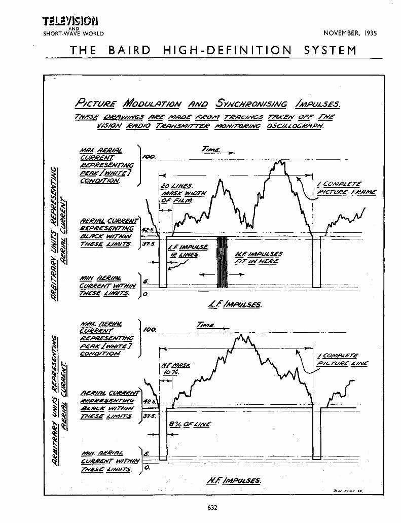
THE accompanying drawing gives complet~ details of the waveform for picture modula
tion aud synchronising impulses. From this it ·will be seen that, using the arbitrary aerial current units of zero to Ioo, the total modulation for synchronising (black) extends between the tolerance limits of zero to 5 and 37·5 to 42.5, while the picture modulation (black to white) extends between the tolerance limits of 37·5 to 42.5 and IOO.
It will be noted that the high-frequency synchronising impulse is rectangular in shape and is maintained for 8 per cent. of the total time taken in tracing the line, and occurs between the line traversals. The lowfrequency synchronising impulse, which is also rectangular in shape, is
maintained during the time that I2 lines are traced, and occurs between the frame traversals. These traversals, as seen by an observer looking at the received image from the front, scan from left to right (line), and from top to bottom (frame).
The diagram also shows that, in addition to the above 8 per cent. of the line traversal time occupied by the high-frequency synchronising impulse, a further 2 per cent. is masked off to form a black edging. Similarly, an additional8lines are masked off in the case of the low-frequency ~ynchronising impulse for the same purpose.
Additional Details
The total number of lines in the complete picture is 240, scanned sequentially and horizontally at 25 pie-
ture traversals per second and 25 complete frames per second. The line-frequency is thus 6,ooo impulses per second and the frame-frequency 25 impulses per second. The dimensions of the observed picture have the ratio of 4 horizontal to 3 vertical.
Amplitude modulation is employed, which results in light intensity modulation in the observed picture, the transmitter carrier increasing towards the white. The line synchronising signals and the frame synchronising signals are in the sense opposite to increasing picture modulation. The ma:>-imum frequency band involved in the transmission is 2 megacycles and the average component of light in the picture is transmitted, a black in the picture being transmitted as black and a white transmitted as white, in accordance with the modulation percentages referred to above.
SPECIFICATION OF THE RADIATED WAVEFORM OF THE MARCONI-E.M.I. SYSTEM
The following information is also given in accordance with the conditions of contract outlined above and relates to the Marconi-E.M.I. high-definition television system.
T HE Marconi-E.M.I. television system transmits 25 complete pictures per second each of 405
total lines. These lines are interlaced so that the frame and flicker frequency is so per second. The transmitter will radiate signals with sidebands extending to about 2 megacycles either side of the carrier-frequency. Good pictures can be received utilising only a fraction of the radiated band, but naturally the quality of the received picture will depend upon the degree to which the receiver makes use of the transmitted band width. The transmitted waveform is shown on Fig. 1.
(I) Line Frequency. I01 I25 lines per second, scanned
from left to right when looking at the received picture.
(2) Frame Frequency. so frames per second, scanned from
top to bottom of the received picture. (3) Type of Scanning.
The scanning is interlaced. Two frames, each of 202.s lines, are interlaced to give a total of 405 lines with a complete picture speed of 2S per second. The line component and the frame component of scanning are regularly recurrent, the interlace being derived from the fractional relationship between line and frame frequencies. An explanation of the method of interlacing is given at the end of this specification. (4) Interval Between Lines.
There will be intervals between the vision signals of successive lines, which intervals provide time for the
631
transmission of a line synchronising signal and also provide time for the return of the cathode-ray beam to the beginning of the next line. The minimum interval between the vision signal of successive lines will be IS per cent. of the total line period (I/ 10,125 second), the first IO per cent. of this interval between lines being occupied by the line synchronising signal and the remaining 5 per cent. by a signal corresponding to " black " in intensity. The remaining Bs per cent. of the total line period is available for transmitting vision signals. {S) Interval Between Frames.
There will be intervals between the vision signals of successive frames. The minimum interval between frames will be IO lines, leaving a
(Continued on page 634)
l!!UYlSlOtJ AND
SHORT-WAVE WORLD NOVEMBER, 1935
THE BAIRD HIGH-DEFINITION SYSTEM
P!crv~E AfoDvt..~rloN RNLJ SYNCHRONISING IMPVJ.SES.
TNES£ .o..e.-9}1(/NC'S t/&!" M-44)£' ,c"RO/t? TR/9C//VCS T..4K.£N Orr TNE
Y/SION .R/9bl0 TR-4/V.s.+?lrTE.R ~NITO.RINC OSC/.I..t.OC-e..4PN.
MN.X. ..9£-RIR..! Ct/R~ENT.
#EP,eE.SENT/NC PERK/ fl'HITE} CON.OITION.
RE.E»IR& ~~'!JI REPAESENTING BL.RCK WITHIN TNES£ ,1./MIT.S:
A-~ESENTING
8.t.RCK W/TN/IV
TNGSE .t./M//..S.
N.F./MPU~S~S
fiT/NH£Al£
LE IMAV..!S£5.
632

·r ~J.aYJSlOtJ NOVEMBER, 1935
AND SHORT-WAVE WORLD
B
'TYPICAL LJN E SIGNALS
DURING FRAMES
SIGNALS AT END OF EVEN FRAMES
SIGNALS AT END OF
ODD FRAMES
I
WHITE t· . I
BLACK--
SYNCH- -!-....._------!-J-
~"" ,.~J., ~~·+ "" ~ .. ~
PEAK Of . CARRIER IOOto
TOLERANCES
__ 30
./ j !3% Dl.IRIN(j ONE ~SMISSION ~•? AND FUI?THER:!:3% ~Vlb~Y
ZERO CARRIER
-------7\ I'OR AT L!AST 10 LINES ---(
I --lr--11'--- jJ__ _u_ ---
1 I 1- UI'IE l'f0?12--j
MARCONI E.M.I. TELEVISION SYSTEM TRANSMITTED WAVE FORM . FIG.I.
A N~----------------~~~------------------~r--=~M -------.. __ _ c --------- 8 -------- _ _.., ------- -------p 0 -·--E ----- ----- --- ----------0 ·----
T
·---------- ----------------
-------------·--------------
-----. -------------
----- -----
633
·------- Q
---- F
·---------------
H -----------s FIG.2.

·ti!LJ!YJSJOIJ AND
SHORT-WAVE WORLD
maximum of I92·S active lines per frame, or 38s active lines per complete picture. (6) Picture Ratio.
The picture ratio will be s : 4, that is to say, the distance scanned during the active 8s per cent. of the total line period will be s/ 4 times the distance scanned during the I92·S active lines of the frame. (7) D.C. Modulation.
The picture brightness component (or the D.C. modulation component) is transmitted as an amplitude modulation so that a definite carrier value is associated with a definite brightness. This has been called " D.C. working," and results in there being n.o fixed value of average carrier, smce the average carrier varies with picture brightness. The radio frequency transmitter output is specified in what follows as a percentage ?f ~he peak output. This percentage 1s m terms of current (or voltage) and not in terms of power. (8) Vision M adulation.
The vision modulation is applied in such a direction that an increase in carrier represents an increase in picture brightness. Vision signals occupy values between 30 per cent. and 100 per cent. of peak carrier. The amount by which the transmitted carrier exceeds 30 per cent. represents the brightness of the point being scanned. (9) Synchronising Modulation.
Si.gnals below 30 per cent. of peak earner represent synchronising signals. All synchronising signals are rectangular in shape and extend dow~wards froi? 30 per cent. peak earner to effective zero carrier. ( 10) Li17;e Synchronising Signals.
The lme synchronising signals are of one-tenth of a line duration, and are followed by a minimum of onetwentieth of a line of black (30 per cent. peak) signal. (I I) Frame Synchronising Signals.
The. frame ~ynchronising signals <:ompnse a tram of two pulses per !me, each occupying four-tenths of a ~ine and having one-tenth of a line 1~terval of black (3o per cent. peak) s1gnal between them. At the end of even frames, the first frame pulse starts coincident with what would have been a line signal. At the end of odd frame~ the first frame pulse s.tarts. half a !me after the preceding !me s1&"nal. At least six frame signals wdl be transmitted at the end of each frame, but the number may be increased to any number up to I2 pulses (6 lines). During the remain-
der of the intervals between frames, normal line synchronising signals will be transmitted with black (30 per cent. peak) signals during the remaining nine-tenths of the line.
It will be noted that throughout the interval between frames (as during the whole transmission) the carrier falls from 30 per cent. to zero regularly at line frequency and in phase with the beginning of the normal line synchronising pulses. (I 2) Variations in Transmitted Wave
form. The IS per cent. interval between
vision signals of successive lines, and the IO lines interval between successive frames ::1re minimum intervals used at the transmitter. During the initial development of the transmitter, certain transmissions may have longer intervals between lines and between frames, which lengthened intervals correspond to the transmission of a black border round the picture.
The 30 per cent. carrier is the " black level " below which no vision signals exist and above which no synchronising signals extend. The mean black level of any transmission will be 30 per cent. ± 3 per cent. of peak carrier. The black level during any one transmission will not vary by more than 3 per cent. of peak carrier from the mean value of that transmission.
The residual carrier during the transmission of a synchronising pulse will be less than s per cent. of the peak carrier.
The line frequency and the frame frequency will be locked to the socycle mains, and therefore will be subject to the frequency variations of the mains. ·
Explanation of Method of Interlacing
The method of interlacing is shown in the drawing in Fig. 2, which r~presents the top and bottom portwns on the scanned area with the distance between the lines very much enlarged. The lines show the track of the scanning spot which moves under the influence of a regular downward motion (frame scan) with quick return and a regular left to right motion (line scan) with very quick
A Simple Explanation of
The Official Specifications appears
on the next page.
634
NOVEMBER, 1935
return (not shown on drawing). The combination of these motions produce the slightly sloping scanning lines. Starting at A, not necessarily at the beginning of a line, the spot completes the line A B, returns to the left and traverses line C D, then E F and so on down the '' dotted '' lines on the drawing. At the bottom of the frame the spot travels along line G H and then starts at J and travels to K. At this point the return stroke of the frame motion begins and returns the spot to L at the top of the frame. A complete frame scan has now been made since leaving A, so that 202t lines have been completed, and the point L is half a line away from A. The downward frame motion now starts again causing the spot to travel along L M completing a single line motion J K L M. The spot then returns to the left and traces out line N 0, which due to L being half a line ahead of A, will lie between lines AB and CD. Similarly the next line P Q will lie halfway between C D and E F. The spot now traces down the chain dotted lines to R S and finally traces out T U, at which latter point the frame return causes the spot to rise again to the top. VVhen the spot reaches the top it will have completed two frames, since leaving A, and, as two frames occupy the time of exactly 40S complete lines, the spot will return exactly to A, after which the cycle begins again.
From the foregoing, it will be seen that the complete picture is scanned in two frames, but as each frame contains an integer number of lines, plus a half, the two frames will interlace. The system does not rerequire the short return times shown for the line and frame scans, nor need the lines begin in the positions shown. Provided the line and frame traversals are regularly recurrent and have the correct frequency ratio (two frames = odd number of lines), an interlaced picture will be obtained.
South London and District Radio Transmitrers Society.
On W~dnesday, November 6, Mr. J. G. Ch1sholm-G2DX-is to deliver a lect~re. entitled the " History and Orgamsat10n of Amateur Radio." On ~o.vember 15 the Society is paying a viSit to the B.B.C. station at Droitwich.
Visitors and prospective members are welcomed to the Society meetings held on the first Wednesday o.f every month at the Brotherhood Hall, Knights Hill, \Vest Norwood, S.E.27. The lectures commence at 8 p.m.

NOVEMBER, 1935
·r ~L!!Yl~lOtJ AND
SHORT-WAVE WORLD
A SIMPLE EXPLANATION OF THE OFFICIAL SPECIFICATIONS
T HE specifications given on the preceding pages may at first sight appear rather complicated and confusing to the amateur, but then no one is
used to these things-indeed they may be said to be the first complete specifications of a television transmission. Neither when the old 30-line system was first broadcast in I929 nor at any period during the six years of its life was there published by those responsible for it any such detailed particulars. Had there been we might now be more prepared for these just issued. However, let us examine and try to interpret them to the extent to which they will affect the average amateur and home-constructor. Where possible we will make appropriate comparisons with the 30-line system with which everyone is familiar.
The Marconi~E.M.I. System
Taking the Marconi-E.M.I. system first as being the more complicated, it is stated that this system transmits 2S complete pictures per second, each of 40S lines. This, of course, is perfectly straightforward and replaces the I2i pictures per second, 30-lines specification of the old system. " These lines arc interlaced so that the frame and flicker frequency is so per second.'' Articles have already appeared in this journal explaining what is meant by interlacing and how it works,* and readers who are unaware of its nature are advised to refer to the issues in which these appeared, while there is also an extra explanation at the end of the specification. Then we are told that there will be 2
megacycle sidebands, i.e., 2,ooo kilocycles. The 30-line system provided side bands of approximately I 3 kilocycles, which is about I/I5oth of the new figure, but as the new wavelength to be used is 6.6 metres, the proportion is quite reasonable, and we shall soon get used to a sideband which itself is a high enough frequency to be a carrier wavelength for sound !
With a lesser maximum side band frequency, which might easily be the case with an improperly designed receiver, it is still possible to receive good pictures. This will be evident because our experience with 30 lines has taught us that there is some entertainment value even with a maximum frequency of I3 kilocycles. The definition of the picture is directly proportional to the frequency, so, for example, a maximum receiver response of I megacycle would give just one-half the detail obtainable with 2 megacycles. The latter is, presumably, the frequency which gives equal definition in both directions, and is about ·4 of the " zero frequency.''
The line-frequency (para. I) of 10,12s is easily derived by multiplying the total number of lines by the pictures per second-4os x 2S = 10, I2S. (It used to be 30 x 12! = 375).
Sl~:r·:_i,~~:la~~rl~~~aJ~\~~·;~3~~ J. McPherson, "Television and
" Time Bases and Interlaced Scanning," by J. McPherson, " Television and Short-Wave World," September, 1935·
635
The frame-frequency (para. 2) becomes double the picture-frequency by the interlacing process. Then follows in para. 3 a brief explanation of the " Type of Scanning,'' viz., interlacing. Obviously, each frame will have half the total number of lines, i.e., 202.s lines.
Intervals between lines are necessary for the transmission of synchronising impulses. This was also the case in the 30-line system when about 10 per cent. of each line was cut off, forming a synchronising pulse and making a black band across the top of the image. In the present case it is stated (para. 4) that the interval will be IS per cent., so that the " remaining Ss per cent. of the total line period is available for transmitting vision signals."
Those who are not yet '' cathode-ray minded '' have got to get used to the idea of two synchronising frequencies, line and frame. The old mechanical systems needed only one, the line frequency (37S cycles with the 30-line system) because, being mechanically coupled, the picture or frame could not help being in synchronism provided the lines were. The frame-frequency was determined by the rate of rotatiJn of the mirror-drum, and so was the line-frequency which the number of mirrors on the drum automatically arranged. The worst that could be wrong when the motor was running at synchronous speed was an out-of-phase (out-of-frame) effect easily remedied by rotating the carcase of the motor. Thus it was only necessary to transmit one synchronising frequency, the line-frequency.
But we find a different state of affairs when we consider the cathode-ray tube. We have two pairs of deflector plates, one pair for making the lines and the other for the frames. But there is no mechanical or electrical coupling between them and it would be quite possible to have one pair working without the other. To make them provide a line screen we have to apply separate frequencies to each pair and in order to ensure that these two frequencies are both of exactly the correct value each has to be controlled or synchronised by special impulses sent from the transmitting end along with the image signal.
The Two Synchronising Impulses
If we tried to adhere to the old method of using only one kind of synchronising impulse we might easily find the tube scanning at the right ~peed with the wrong number of lines !-an impossible condition, of course, with mechanical scanners. Thus in order to ensure that televiewers with cathode-ray receivers will be able to operate them satisfactorily both systems have made provision for the two required synchronising frequencies. In the case of the line-frequency this is achieved, as already pointed out, by sacrificing a certain percentage (I 5) of each line.
Similarly, the frame frequency necessitates encroaching on a portion of each frame, a minimum (para. S) of nearly 5 per cent. This corresponds to 10 lines per

·ri!UYJ$JOtJ AND
SHORT-WAVE WORLD
frame, or 20 per complete picture. In order, therefore, to ensure correct synchronisation, we have lost 20 lines out of 405, and 15 per cent. of each line; in other words, about 20 per cent. of the image size is cut.
Passing on to the other details of the specification, we find in para. 6 that the picture ratio is to be 5: 4· The scanning is horizontal and the observed image will be five units in width by four in height. This contrasts with the very different shape of the 30-line image which used to be one unit wide by just over two in height.
Para. 7 is an important one and introduces another new conception compared with the old technique, viz., " D.C. working." This was foreshadowed in a previous article to which the reader is referred.* What it means, briefly, is that the ayerage brightness of an image is transmitted, so that at the receiving end pictures having different average brightnesses at the studio end will not all appear to have the same, which used to be the case with the old 30-line system.
NOVEMBER, 1935
transmitting the sychronising impulses, and so it is arranged (para. 8) that the minimum vision carrier strength, corresponding to a black, be 30 per cent. of the maximum xoo per cent. The remainder of the carrier strength (para. g) from zero to 30 per cent. is used for fitting in the synchronising pulses, clearly shown in the diagrams. Incidentally, this is an ideal arrangement because there is no confusion whatever between vision and synchronising pulses which •vas always a trouble with the 30-line system when the synchronising pulses and " black " vision strength was exactly the same, the synchronising in consequence being sadly impaired.
Paragraphs 10, II and 12 are more technical elaborations of paragraphs 4 and 5, and for the present the reader will probably have had enough information to digest. There follows an explanation of the method of interlacing which should be studied.
vVe come now to details of the Baird wave-form, which are found to be remarkably similar to the Mar-
SUMMARISED INFORMATION. -----
SYSTEM. PARTICULARS.
BAIRD. MARCONI-E.:\LI.
Number of lines (nominal) ... . .. ... 240 405 -
;";"urn ber of lines (effective) ... . .. ... 220 385
Type of Scanning ... ... . .. . .. Sequential Interlaced
Ratio-Width: height ... ... ... 4:3
I
5:4
Frame and flicker frequency ... ... 25 50
Picture frequency ... ... ... . .. 25 25
Line frequency ... ... ... . .. 6,000 10,125
?liethod of modulation ... ... ... Amplitude, with carrier. value prop. to D.C. Amplitude, with carrier. value prop. to D.C . component component
Carrier limits for vision ... ... ... Approx. 40 to lOO% of carrier value Approx. 30 to lOO% of carrier value
Carrier limits for synch. ... ... . .. Approx. 0 to 40% of carrier value Approx. 0 to 30% of carrier value
Number of line synch. impulses ... ... l between each line I between each line
Portion of line occupied hy sync h. impulse ... 10% 15% I
Number of frame synch. impulses ... . .. 1 between each frame
I
6-12 between each fram<'
Portion of frame occupied hy sync h. impulses 8.3% approx. 5~0 -I
:\faximum f1eqnencv hrmd ... . .. . .. 2 megacycles ', 2 IPC&Ul cveles
A convenient way of transmitting a component proportional to the average brightness, which, of course, varies continually from picture to picture, is to make the strength of the carrier current so proportional. It is quite a new idea, because with sound or the 30-line broadcasting the carrier would still go on radiating even if no modulation at all were being applied; now when the modulation ceases the carrier drops to a low value, though not to zero as the next paragraph explains. A bright picture will send up the carrier strength more than a dull one, and if at the receiving end we make the rectified carrier current operate the bia-;ing potential of the cathode-ray tube or other modulating device we can secure the proper contrasts.
Some of the carrier, however, has to be reserved for
* " There is ~omething Lacking in Television," by J .McPherson, " Television :1nd Short-\V:we World," August, 1935·
636
coni-E.M.I., and we need not go into further explanations but rather compare the one with the other. \Ve first see that the synchronising impulses are tr8.nsmitted in the same way and that approximately 40 per cent. instead of 30 per cent. of the carrier strength corresponds to no vision modulation, i.e., black.
Then it is stated that 10 per cent. of each line is curtailed in order to fit in the line synchronising impulses (as compared with I 5 per cent. in the case d E.M.I.), while 20 lines, i.e., 8.3 per cent. of a frame, are lost while the frame synchronising takes place (as compared with 20 and 5 per cent. respectively). Thc;-efore, 18.3 per cent. (compared with approximc~tely ::o per cent.) of the image space is sacrificed for accommodating the synchronising pulses. The tote'~! ll\Imb('r of lines is z_~o, non-interlac('d, so that hoth pictun' anrl
(Continued on page 6 8 8)

NOVEMBER, 1935
All waves * * *
A.C.-D.C.
* * * uo-250 volts
* * * Any frequency
A.C. mains * * *
Single-dial control
16-2,ooo m. * * *
Four Bands
* * * Aero Dial
Vtsual T;mn6 ,.
·r~UYl~lO!'l AND
SHORT-WAVE WORLD
Diode detector 5-9 Kc. Selectivity
* * * Visual Tuning
* * * Gramo Pick-up
* * * No Transform
ers * * *
3 Watts Output
* * * R.C. Coupling
* * * Five Valves
The Advance All-waver This receiver for the home-constructor has been designed on commercial lines. It has all the features to be found in advanced commercial all-wave sets and can be built quite
cheaply. No special components are required.
ONE of the most important developments in commercial set design this year has been the
introduction of all-wave receivers of an ambitious type. Every would-be buyer of a new set has inquired as to the possibilities of an all-waver so that American and other interesting programmes could be received.
Constructors who like to build their own receivers have complained that no set design was available to cover a receiver having all the features embodied in commercial sets.
We have been experimenting for some considerable time on a receiver on these lines which would not cause the constructor any difficulty in building. At the same time, all the very necessary features, such as variable selectivity, visual tuning, automatic volume control and so on, would have to be included. Special components make a receiver expensive to build. All of these points had to be carefully considered before the receiver was designed. Finally we evolved a circuit which has been well tried and is reason-
ably flexible, so that small variations in component characteristics do not upset the performance.
The Advance All-waver uses five 13-volt A.C.JD.C. valves. The aerial feeds into a coupling and grid coil which are across the grid cathode circuit of an X3o heptode. This valve combines the functions of oscillator and first detector in the most efficient manner. Once and for all it completely overcomes the need of voltage adjustment in the detecctor-oscillator circuit as with other types of valve.
The circuit dearly emphasi.se.s the numerou.r outstanding features of thi.s all-wave .superhet.
637

I .21! 'I J~JO!'J AND
SHORT-WAVE WORLD
The circuit actually is the feature of the receiver. Four coils connected across a four-section switch, each section with ten contacts, enable the receiver to be switched from 15 to 2,000
metres in four wavebands. From the anode of the X30 the sig
nal is fed into an I.F. transformer wound with Litz. wire, which, by virtue of its construction, is far more efficient than the ordinary type of transformer wound with solid wire. The transformer i5 suitable for frequencies of between 450 and 465 kc. and can be adjusted by simply balancing up the trimmers mounted m the coil can.
The second valve is a W31 high-frequency pentode, which is A.V.C. controlled with the X3o. This gives automatic-volume control on two stages and accounts for the fact that as far as A. V. C. is concerned the receiver is almost 90 per cent. effective on medium and long waves, and about 75 per cent. effective on short waves. This is a very high degree of efficiency.
In the anode circuit of the I.F. amplifier is the visual tuning meter. It consists of a special type of lowreading milliamp meter, swinging from zero towards maximum as the station is tuned in. By means of this meter it is impossible wrongly to adjust the set, so that quality is always of a high order.
The second I. F. transformer calls for special attention. Normally, the receiver has a band width of 9 kilocycles, sufficient to deal with the present congested state of the ether, and enables all stations which adhere
to the Lucerne Plan to be tuned in I without interference.
With the variable selectivity device
NOVEMBER, 1935
Components for the Advance All-waver CHASSIS. r-aluminium 16 x 10 X 3 (Peto-Scott). CABINET. r_,;pecial console (Peto·Scott) CHOKE, H.F. r-H.F.P.J. (Wearite) CHOKE, L.F. 1-3o-henry 6o-mfa. (Bryan Savage). COILS. I-CS2lBulgin). r-Cs3 Bulgin). CONDENSERS, FIXED. 2-.ooo2-m!d. type M ~T.C.C.). 2-.ooor·mfd. type M T.C.C.C.). r-.oor·mfd. type M. (T.C.C.). r-.ooo3·mfd. type M (T.C.C.). 3-.or·mfd. type tubular (T.C.C.). I-Io·mfd. type C (T.C.C.). ro-.I·mfd. type 300 (T.C.C.). r-.or-mfd. type 300 (T.C.C.). r-.o2·mfd. type 300 (T.C.C.). 2-8-mfd. type 502 (T.C.C.). CONDENSERS, PADDlNG. I-.0002·mfd. (J.B.). r-.ooos·m!d. (J.B.). CONDENSERS, VARIABLE. r-.ooos·mfd. 2-gang type 2121 (J.B.). DIAL, SLOW -MOTION. 1-Aero type with trimmer (J.B.). HOLDERS, FUSE. r-t·amp. (Micro!use). Holders, Valve. 5-7-pin chassis mounting type V2 (Clix). KNOBS. r-set of five matched knobs type K40 (Bulgin). LOUD-SPEAKER. r-Stentorian Baby (W.B.).
brought into operation, the selectivity can be increased up to 5 kilocycles, so that when two stations are too close together they can be separated without much difficulty. We do not like the manual control of selectivity where a secondary coil is rotated so that the coupling between it and the primary is decreased. This only gives a very rough control. The coils we have used have a third winding which is shunted by a fairly low resistance potentia-
meter, and by varying this resistance I the selectivity can be adjusted between 5 and 9 kc. in fine steps.
638
METER, TUNING. r-magnetic tuning meter type VTso (Bulgin). PLUGS, TERMINALS, ETC. 8-insulated sockets type n, and plugs type u RESISTANCES, FIXED, (Clix). 3-ro,ooo·ohm r-watt (Erie). 3-.s-megohm r-watt (Eric). 2-5o,ooo·ohm I·watt (Erie). I-250·ohm I·Watt (Ene). 1-2oo·ohm r-watt (Erie). I-350-ohm I·watt (Erie). 1-750·ohm I·watt (Erie). r-2o,ooo-ohm I·watt (Erie). 2-.25-megohm 1-watt (Erie). I-IOO,OOO·ohm I·Watt (Erie). r -soo-ohm r-watt (Erie). RESIST ANCES, VARIABLE. r-s,ooo-ohm potentiometer (Varlev). r-.s-megohm (Reliance). · r-mains resistance to specification (Bulgin). SUNDRIES. r-insulated coupling piece (J.B.). 3--<ihielded anode connectors (Belling Lee). 3-coils Quickwire (Bulgin). Quantity 6 B.A. nuts and bolts (Peto·Scott). SWITCHES. 1-SL22 (Bulgin). r-S88 (Bulgin). TRANSFORMERS, I.F. r-Cso (Bulgin). 1-C51 (Bulgin). VALVES. r-X30 (Osram). r-W31 (Osram). r-DH3o (Osram). r-N30 (Osram). r-U30 (Osram).
Double-diode-triode valves are rather inclined to be viewed with suspicion, but the modern valve of this type when used with the correct circuit is absolutely fool-proof, and, as it has three electrode systems in one bulb, it would be the ideal valve for the purpose.
The output from the second I.F. transformer is fed into one diode used as a speech detector. It is common knowledge that to obtain perfect rectification in a modern high-gain set,
A full-size Blueprint of
the Adl!anceAll-Waver
is available, price 2/6
Neat construction and com
mercial set appearance are hw
of the mtijor points in thi r
receiver.
diode detection has to be used. The second diode is used to supply automatic volume control bias to the grins

NOVEMBER, 1935
of the W3r and X3o, while the triode section of the valve is a normal resistance-coupled low-frequenccy amplifier.
A gramophone pick-up can be connected in the grid circuit of this DH3o, while the volume control across it operates on both radio and gramophone without alteration. The anode of the DH3o is then R.C. coupled to an N3o steep slope pentode giving an output of over 3 watts.
Finally, comes the full-wave U3o rectifier. This valve is so coupled that
it acts as a half-wave rectifier on A. C. mains and will provide up to 120 milliamperes of D.C. current. When on D. C. mains it is more or less a passenfer and fulfills no useful purpose.
Although only five valves are used, as the X3o is a triode and a screened grid combined, and a DH3o is three valves in one, the receiver has the performance of what would normally be a conventional eight-valve super-het.
We have already been asked how it is that with all these undoubted refinements the receiver is so much cheaper than the nearest commercial equivalent. The reason is that by the use of A.C.fD.C. valves and valves of certain characteristics, we have been able to omit the use of a mains transformera very expensive component, a lowfrequency transformer and sundry other components such as various resistances and H.F. chokes. The number of resistances has been kept down to a very low number, while only one high-frequency choke has been used in the entire receiver. The output transformer has also been omited for this is embodied in the loud-speaker we specially chose to match up with the N 30 output valve.
All wave changing is accomplished by means of one calibrated switch which is also used to cut out the radio side of the receiver and link up the gramophone pick-up. Providing the pick-up has an output of more than . 5 volt R.M.S. it is suflcient to load the DH3o so as to obtain over 3 watts output from the N 30. If a needle armature type pick-up is used an input transformer for voltage step-up will be requirf'd.
It is most important with an A.C.f
·r.eliYJ$JON AND
SHORT-WAVE WORLD
can be out of line. As the receiver is so completely flexible in every way valve or coil variations can be taken up quite easily.
A fuse is in one side of the mains supply and this must be of a special type. It is a gold leaf Microfuse which is very sensitive to overloads, so that in case of errors in construction no damage to components can result. The mains voltage dropping resistance which is mounted parallel with the chassis has to be adjusted to either r 10
ThiJ plan view .rhow.r how the
components are laid out and the neatne.r.r of the vi.rihle
wiring.
fa ~~e\ L.F. ehoke ~ctfY!'
D.C. set of this kind that both aerial and earth be isolated from the receiver, and for this reason a .or-mfd. condenser is in series with the lead-in and a . r-mfd. in series with the earth lead.
As would be expected, it is almost impossible to obtain complicated coils of the type used to match up without some difficulty. So as to make quite sure that even a non-technical constructor will not have any difficulty-for ganging is always a problem-we have embodied one or two features to counteract even this possible difficulty to the constructor. First of all, the main tuning condensers do not require ganging. A small variable trimmer is fitted to the aero tuning dial and, if at any wavelength the condensers go out of step,. they can be balanced externally by means of this small trimmer. As the trimmer knob is concentric with the master tuner the extra control is not noticeable.
In addition to this, a .0002 mfd. and a .0005 mfd. trimmer are connected in series with certain sections of the oscillater coils, so that these can be adjusted before the receiver is put permanently into use thus making absolutely sure that throughout the whole set nothing
639
or between 200 and 250 volts, after which it need not be touched.
We cannot see where any difficulties will be encountered in the construction. The photographs show quite clearly the layout of the components, while a full-sized wiring blueprint can be obtained from our Blueprint Department at Chansitor House, 37/8 Chancery Lane, London, vV. C. 2, price 2s. 6d. The number is SW2o6.
Construction First of all mount the valve holders.
A r-in. centre bit will cut out the holes in the aluminium quite easily. The coil units are fixed by nuts and bolts, but small holes have to be drilled underneath so as to enable the tag contacts to go through the chassis without touching. An oblong strip, one inch long by a quarter-inch wide, has to be cut out of the chassis beneath the tuning drive so that the trimming condenser does not foul. Controls are arranged symmetrically along the front of the chassis, but the holes for these are of the normal size and can be cut with a twist drill. Neither of the potentiometers need be isolated from
(Continued at foot of p:zge 64 I)

·raLi!YISJOIJ AND
SHORT-WAVE WORLD NOVEMBER, 1935
The Short-wave Radio World Over Modulation Indicator
W E were particularly interested in the linear rectifier used for determining the limit of modu
lation to which a phone transmitter can be operated described in Radio for September. In America the F.C.C. regulations call for some means of measuring the depth of modulation which must be in continual use. A well designed and adjusted phone will allow up to 100 per cent. modulation, although many amateur stations overmodulate before reaching 100 per cent.
r.--- Lea.d n..ea.r ACrl<;:\.l
~0005
Over modulation can be checkd immediately with this simple meter.
This causes needless interference and is in the same category as bad keying.
The linear rectifier shown in Fig. 1
indicates the slightest amount of carrier shift or over-modulation. It uses a small variable condenser for adjustment of the meter deflection, while a so-mfd. fixed condenser and TOO-rr!fd. variable condenser form a variable attenuator for R.F. voltage. Capacity coupling is used for the aerial by simply running the lead from the unit close to the feeder.
Any type of diode or strapped gridplate triode can be used, while the actual connections and supply are selfexplanatory. The R.F. choke has an inductance of 2.5 mh. This type of over-modulation indicator must not be
{ I
A Review of the most Impor·
tant Features of the W orld'e
Short-wave Literaturr.
used with controlled carrier modulation transmitters.
A Sensitive Receiver
The Sydney Bulletin (which is not actually a radio paper) published in their August 21 issue a simple twovalve receiver that can be constructed from English components.
It consists of a high-frequency pentode detector, such as a Mullard SP4, choke-capacity coupled to a triode output valve such as an ACJP. As the heaters are run from A. C. a filament transformer will be required giving 4 volts 2 amperes. High-tension can be obtained from batteries or a standard B.C.L. mains unit. The reaction coil is connected between cathode and chassis, while regeneration is controlled by means of a so,ooo-ohms potentiometer which adjusts the voltage to the screen of the pentode. The L. F. choke in the anode of the detector is of the high-inductance type, such as the Varley DP16, which has an inductance of 300 henries at 10 milliamperes.
Although the coils can be purchased from Bulgin, Eddystone, or B.T.S., and are quite suitable without alteration, the following coil data shou!d be of intP.reot to constructors.
For wavelengths of between 15 and 32 metres, the grid coil is 5 turns, the cathode coil 4 turns, with a k-in. gap between coils. 30 to 55 metres, grid coil 12 turns, cathode coil 4 turns, space between coils i in. 50 to 90 metres, grid coil 24 turns, cathode coil 5 turns, with a i in. gap between coils. 8o to 200 metres, grid coil 40 turns, cathode coil 7 turns, !-in. gap between coils. 26 gauge d.s.c. wire is used throughout, while the formers are of
T so,ooon
English made components can be used in this Australian two valve receiver.
640
the standard four-pin variety. Provided that the receiver is built on a metal or metallised chassis hum will be entirely absent. We can recommend this type of receiver for the use
• of the beginner or for ham band use.
Duplex Phone Working
W9CPW has a neat idea to improve duplex phone working. At the present time there seems more interest in this end of amateur radio than ever before. \Vhen listening to a long report very often details are forgotten which could not happen with duplex phone working. A shielded input tuning circuit does help very considerably to overcome grid blocking, and in view of the fact that the circuit is so simple it is well worth a trial.
Amongst the components required are two .00025 or .00035 mfd. BCL type tuning condensers, two dials anrl a plug-in coil former. This system is applicable to all bands and here are the details for x6o metres which is ideal for duplex working. Two turns of No. 20 rubber covered wire are used for the pick-up L2, placed xf3rd of the way down from the aerial on LI. Connections from L2 run through a shielded two-wire cable in the aerial coil in the receiver. Natura 11 y this aerial coil should be disconnected on its earthy side.
Good shielding of both receive:- and duplex system is essential, the shielded cable connecting the common earth.
r------,
I ['
I I L I
s·~---~ ------=~ 8 : Lt j : I
1 ....------Screen..__________..... R..eceJvE-r I L----~---l L ______ J
Duplex phone working is the centre of interest at th. moment.
Length of aerial is more or less optional depending on the amount of grid blocking and sensitivity of the receiver. In the case of W9CPW a five-foot vertical wire is used, giving, of course, excellent selectivity with a reasonable signal level, but up to 20 feet could be used without any trace of grid blocking. The system is tuned by using a regular long receiving aerial connected directly to one side of the open aerial coil of the receiver. After a station has been tuned in, the volume control on the receiver is slightly advanced and the long aerial disconnected, so leaving the duplex system in operation. Cr across Lx is adjusted until maximum signal strength is obtained, C2 being set to about half capacity and tuned for sharpest signal

NOVEMBER, 1935
after the required frequency has been turn spiral with adjustable coupling to obtained. ' L1. Cr is s-mmfd., C2 so-mmfd., C3
.oo2f.oo6 mfd., C4 ro-mfd., Lr 8 turns of r8-gauge wire ~-in. diameter, turns spaced the diameter of the wire. The H. F. choke consists of 45 turns, 2'6 gauge d.c.c. wire wound on a :i-in. rod, after which the rod is removed. Rr as high as possible up to ro megohms, R2 so,ooo ohms potentiometer, R3 so,ooo ohms fixed resistance, R4 2,000 ohms fixed resistance.
A 56-MC Super Regen
Five metres in America seem to be progressing very favourably, although we in this country appear to have superior receivers. Dwight Hill, \V diU V uses a very simple super-
H.T.+ 250V.
This i.r 011 of tLe simplest two vatve 5 metre receiv.1r s 1ve have .reen so f•r.
~·egen. which is used pretty generally m Boston. The circuit is almost selfexplanatory. The detector valve is a Hartley oscillator, transformer coupled to a conventional L. F. pentode. Selectivity is claimed to be higher than with a normal super-regen. but there are several points which must be remembered.
All earth connections must be brought to a single point on the chassis. The detector valve must be mounted horizontally with the anode pin soldered to the junction of the condenser and coil with just enough space between the grid pin and the other end of the coil to accommodate a midget grid condenser. The receiver should be considered unsatisfactory unless the detector operates with 25 volts or less on its anode. The aerial coil is a five-
"The Advance All-Waver" (Continued from page 6 3 9)
the panels or bushed in any way, for we have taken the precaution of using components having dead spindles.
A most important component is the dial light. This is a 6-volt .3-amp. Osram bulb which is in series with the heaters of the five valves and comes between the rectifier and N 30 heaters. This bulb is most reliable in use and it is folly to use a cheap bulb or one of the wrong amperage in this position.
Although none of the components are actually special types, no alternatives can be used in any position. The circuit, an intricate one, has been designed around the components used so that an unusually high degree of efficiency has been used.
Readers have asked for sets built on commercial lines, and we have obliged with this set which will be free from
c
A Five-metre Pre-Selector
Radio frequency amplification on 5 metres does, at first, seem rather ridiculous, but R. F. gain at that frequency really is possible and naturally is very useful in front of either a superhet or super-regenerative receiver. W5XM, of Dallas, Texas, is using a 954 Acorn valve with which he obtains an audible increase in amplification on weak signals. The valve in use is one of the new Acorns which can be obtained from Claude Lyons, so removing any difllculty in construction.
R. F. amplification can be obtained down to 5 metres with circuit U'hich uses, an "Acorn
valve.
t.T.-The circuit is sufficiently self-ex
planatory for the average amateur but construction requires a few comments. Grid and plate circuits must be care-
the usual constructor troubles providing it is built to specification. We have anticipated as far as possible the usual mistakes made by constructors and have designed the set so flexibly that the usual alterations in layout, etc., can be tolerated.
Sensitivity with 9 kilocycles separation is in the order of I~ micro-volts per metre at 300 metres, but to obtain this sensitivity the receiver must be built exactly as the original model.
In case it has not been realised just what this receiver will do, commercial short-wave stations between I 5 and 5 I metres can be received on the loudspeaker, the American broadcasters on 16-, 19-, 25-, 31- and 49-metre bands can, according to our tests, and from outside tests, be received loud enough to be of entertainment value, while many amusing hours can be whiled away by listening to amateurs on the 20- and 40-metre band.
641
"I2Jj'JJ~lOtJ AND
SHORT-WAVE WORLD
fully screened from one another otherwise the receiver will tend to oscillate due to feed-back. This screening is obtained by placing a metal " floor " or chassis half way up the cabinet and utilising the space beneath for the grid circuit and the space above for the anode circuit.
The valve is mounted on this floor with the grid terminal going down through a hole. R. F. chokes are wound on :i-in. rods using 20 turns of 30-gauge single cotton-covered wire with slight spacing between turns. The rods are tapped at one end and screwed to the baseplate.
Under normal conditions anode current is between r and 2 milliamps, but if battery bias is used and the valve goes into oscillation this current rises to 20 milliamps. In the circumstances it is advisable always to include auto bias to prevent injury to the valve.
During tests with a rSo-volt anode supply and. 90 volt screen supply, a cathode resrstance of r,soo ohms was required. The Acorn valve has to be handled very carefully; input and out-
put terminals must be well separated while all earth returns must be kept short and taken to a common point on the chassis.
These stations are, of course, in addition to the usual run of mediumand long-wave broadcasters between 200 and 2,000 metres.
'' A Guide to Amateur Radio," third edition, is now available, price 6d., from the Radio Society of Great Britain, 53 Victoria Street. It is the most comprehensive book dealing with short-wave technique published in this country, and those interested in short waves should make a point of obtaining a copy.
A very full explanation on all branches of short-wave radio is given, plus many other articles such as modern valves and their application, aerial systems, power supplies for short-wave transmitters, artificial aerials and frequency measurement. There are almost a hundred pages, all of which are of particular interest to short-wave fans.
"I!!UY~JOJ'J AND
SHORT-WAVE WORLD NOVEMBER, 1935
KERR CELL DESIGN FOR By L. M. Myers
240-LINE OPERATION In view of the importance of the subject at the present stage we publish below the lecture given by L. M. Myers before the Television Society on April wth, I935, on the necessary modifications in Kerr cell design for high definition practice. This lecture is also published in the June issue of the
journal of the Television Society.
UP to the present time it has been considered most expedient to employ tbe Karolus multi
plate electrode cc for television pictures up to roo lir, The limitations in the use of such Kerr cells are im-
microfarads to r ,ooo micro-microfarads; thus the capacity reactance is too low for a frequency exceeding roo kilocycles, which represents the maximum frequency of roo-line picture. \Vhen we come to 24o-line pictures
-'14 Plale
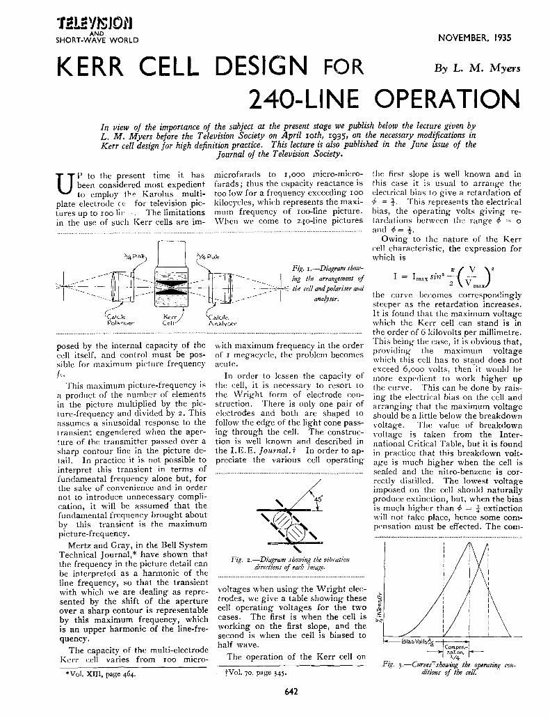
posed by the internal capacity of the cell itself, and control must be possible for maximum picture frequency fc.
This maximum picture-frequency is a product of the number of elements in the picture multiplied by the picture-frequency and divided by 2. This assumes a sinusoidal response to the transient engendered when the aperture of the transmitter passed over a sharp contour line in the picture detail. In practice it is not possible to interpret this transient in terms of fundamental frequency alone but, for the sake of convenience and in order not to introduce unnecessary complication, it will be assumed that the fundamental frequency brought about by this transient is the maximum picture-frequency.
Mertz and Gray, in the Bell System Technical Journal,* have shown that the frequency in the picture detail can be interpreted as a harmonic of the line frequency, so that the transient with which we are dealing as represented by the shift of the aperture over a sharp contour is representable by this maximum frequency, which is an upper harmonic of the line-frequency.
The capacity of the multi-electrode Kerr cell varies from roo micro-
*vol. XIII, page 464.
Fig. r.-Diagram show
-------- I _ ing the arrangem_ent of ___ ~ __ _;_-~~,-- the cell and po/artser and
_ - anafyser.
with maximum frequency in the order of r megacycle, the problem becomes acute.
In order to lessen the capacity of the cell, it is necessary to resort to the \Vright form of electrode construction. There is only one pair of electrodes and both are shaped to follow the edge of the light cone passing through the cell. The construction is well known and described in the I.E. E. Journal. t In order to appreciate the various cell operating
Fig. z.-Diagram showing the vibration directions of Mch image.
voltages when using the Wright electrodes, we give a table showing these cell operating voltages for the two cases. The first is when the cell is working on the first slope, and the second is when the cell is biased to half wave.
The operation of the Kerr cell on
tVol. 70, page 345·
642
the first slope is well known and in this case it is usual to arrange the electrical bias to give a retardation of cf> = f. This represents the electrical bias, the operating volts giving re!ardations between the range cp = o and cf>= !-
Owing to the nature of the Kerr cell characteristic, the expression for which is
I = I sin2 ..!:._(5_)2
max 2 V max
the curve becomes correspondingly steeper as the retardation increases. It is found that the maximum voltage which the Kerr cell can stand is in the order of 6 kilovolts per millimetre. This being the case, it is obvious that, providing the maximum voltage which this cell has to stand does not exceed 6,ooo volts, then "it would be more expedient to work higher up the curve. This can be done by raising the electrical bias on the cell and arranging that the maximum voltage should be a little below the breakdown voltage. The value of breakdown ,-oltage is taken from the International Critical Table, but it is found in practice that this breakdown voltage is much higher when the cell is sealed and the nitro-benzene is correctly distilled. The lowest voltage imposed on the cell should naturally produce extinction, but, when the bias is much higher than cf> = t extinction will not take place, hence some compensation must be effected. The corn-
Com.pen.-,
5~~n. r-Fig. 3.-Curves-.rhowing the operarin.f!_ con
ditions of the cell.

NOVEMBER, 1935 "l !!Li!YlSJOl'J
AND SHORT-WAVE WORLD
pensation resorted to is in the form of a retardation plate of mica. This material possesses roughly the same polarisation disposition as the nitrobenzene. Referring to Fig. 1, such an example is given in which the bias volts give a retardation of r/> = i and the compensation is equal to rf> = i· This being the case, a new operating
polariscope, a description of which is given by the writer in TELEVISION AND SHORT-WAVE WoRLD, Vol. VIII, pp. 277-279, May, 1935.
If a circular polariscope is not used, it 11·i1! be necessary to increase the distance between the electrodes as in Fig. 2, in order that the direction of the field is disposed 45° to the direc-
out of the circular polariscope but does not include the quarter wave plate to effect the necessary compensation essential to the operation of the cell as set out in Fig. 1. The quarter wave plates shown in Fig. 3 are introduced to produce the circular polariscope and the vibrating directions of these two plates will be mu tu-
VOL TAGES FOR KERR DIVERGING ELECTRODES
Electrode Electrode length in gap in mm.
No. cm. a b
Peak Voltage for <P=
1 1 4 2
Control Volts for <P=
t ! I 4 I 2 2,500 3,IOO Boo I,OOO 2 4 ·75 2 2,000 2,6oo 750 6oo 3 4 I 3 3,300 4,150 I,OOO 85o 4 4 ·75 ")
,) 2,400 3,IOO 900 700 5 5 I 3 3,000 3,900 900 900 6 5 ·75 3 2,150 2,700 65o 550 7 5 I 4 3,400 4,400 I,020 I,OOO 8 5 ·75 4 2,500 3,200 740 700 9 6 I 4 3,000 3,900 900 900
IO 6 ·75 4 2,300 3,000 68o 700 II 6 I 5 3,400 4,400 I,ooo I,OOO 12 6 ·75 5 2,6oo 3,400 760 8oo
curve will be produced which is shown in the full line; This new operating curve is much steeper than the first slope curve. The second table gives roughly the operating speed and bias voltages for Kerr cells with diverging electrodes. The possibility of using double image arrangements with this cell is effected by employing a circular
tion of vibration of the two beams. Such electrodes are given in full lines. On the other hand, if we use a circular polariscope, the electrodes can be arranged in accordance with the dotted line. In this case the vibration of the two beams is circular, one being left-handed and the other righthanded. Fig. 3 shows the whole lay-
A NOVEL SCANNING CIRCUIT
ANEW form of sweep circuit for cathode-ray tubes, which can be adapted for television scanning
has been designed by Goldsmith and Richards.* It is well known that cir-
I OocillaTor
---~--------~~--------~~Hi
S canning circuit employing hard valves.
cuits using hard valves instead of the conventional gasfilled relay for discharging the sweep circuit condenser are more stable and are not affected by temperature changes. The disadvantage of such circuits is in the mul-
* Proc. I.R.E. Vol. 23, p. 653. 1935
tiplicity of valves required, since it is not practicable to obtain the discharge action of the relay by the use of a single valve.
In the circuit described the charging condenser is fed through a screened pentode acting as a constant-current charging device in the usual way. This is shown as V, in the diagram. Across the condenser is a discharge valve, V,, which in the original circuit is a type 59 American valve. The anode of this valve is connected to the charging condenser, while the grid is directly connected to the output of an audio-frequency oscillator, which can be of the Hartley type.
The grid of the discharge valve is normally biased several volts negative by a battery inserted in the oscillator coil. By adjusting the bias of the valve, no current flows in the anode circuit until a minimum peak value of oscillatory voltage is reached. At this value the grid of the valve
643
Bias Voltage Cell for <P = capacity
t 1 in m.mfds. 2
I,9oo 2,500 I)
I,400 2,000 9 2,450 3,300 7 I,700 2,400 8 2,IOO 3,000 8 I,6oo 2,I50 9 2,400 3,400 7 I,8oo 2,500 8 2,IOO 3,000 8 I,6oo 2,300 9 2,400 3,400 7 I,8oo 2,6oo 8
·~~~~
ally at right angles and disposed at i 5° to the principal plane of the polariser and analyser. The compensation plate may be introduced anywhere between the two quarter wave plates and the vibration direction of this compensation plate must be disposed at +5° to either of the quarter wave plates.
swings positive and a sudden release of anode current takes place which discharges the condenser. The grid must necessarily stay positive for a sufficient length of time to discharge the condenser completely. It appears from the foregoing that the waveform of the oscillation should be a single highly damped pulse of voltage, since if two peaks occur of the same amplitude the condenser will be discharged again on the start of the charging cycle.
The authors point out the necessity of shielding the driving oscillator from the output circuit. Synchronising to a given frequency is accomplished by a small coupling into the oscillator circuit.
If driven from a controlled frequency this circuit would seem to be an interesting alternative to the various types of scanning circuit de,·eloped using hard valves, and as such is worthy of note.
Reference is also made to Zworykin's paper on the " Kinescope " (Proc. I.R.E., Vol. 21, p. 165s, 1933)·
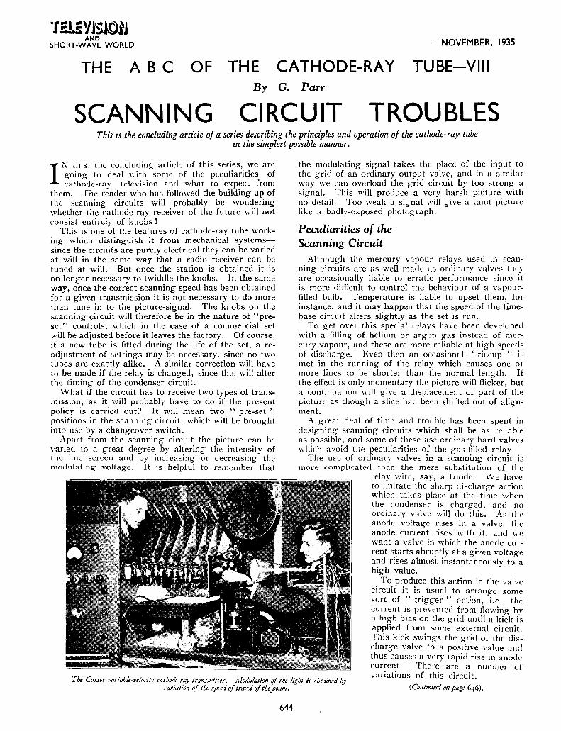
·r 2U Y JSJOIJ AND
SHORT-WAVE WORLD
THE ABC OF
NOVEMBER, 1935
THE CATHODE-RAY TUBE-VIII By G. Parr
SCANNING CIRCUIT TROUBLES This is the concluding article of a series describing the principles and operation of the cathode-ray tube
in the simplest possible manner.
IN this, the concluding article of this series, we are going to deal with some of the peculiarities of cathode-ray television &nd what to expect from
them. fhe reader who has followed the building up of the scanning circuits will probably be wondering whether the cathode-ray receiver of the future will not consist entirdv of knobs !
This is one ~f the features of cathode-ray tube working which distinguish it from mechanical systems-since the circuits are purely electrical they can be varied at will in the same way that a radio receiver can be tuned at will. But once the station is obtained it is no longer necessary to twiddle the knobs. In the same way, once the correct scanning speed has been obtained for a given transmission it is not necessary to do more than tune in to the picture-signal. The knobs on the scanning circuit will therefore be in the nature of "preset" controls, which in the case of a commercial set will be adjusted before it leaves the factory. Of course, if a new tube is fitted during the life of the set, a readjustment of settings may be necessary, since no two tubes are exactly alike. A similar correction will have to be made if the relay is changed, since this will alter the timing of the condenser circuit.
What if the circuit has to receive two types of transmission, as it will probably have to do if the present policy is carried out? It will mean two " pre-set " positions in the scanning circuit, which will be brought into use by a changeover switch.
Apart from the scanning circuit the picture can be varied to a great degree by altering the intensity of the line screen and by increasi:1g or decreasing the modulating voltage. It is helpful to remember that
the modulating signal takes the place of the input to the grid of an ordinary output valve, and in a similar way we can overload the grid circuit by too strong a signal. This will produce a very harsh picture with no detail. Too weak a signal will give a faint picture like a badly-exposed photograph.
Peculiarities of the Scanning Circuit
Although the mercury vapour relays used in scanning circuits are as well made as ordinary valvPs they arc occasionally liable to erratic performance since it is more difficult to control the behaviour of a vapourfilled bulb. Temperature is liable to upset them, for instance, and it may happen that the speed of the timebase circuit alters slightly as the set is run.
To get over this special relays have been developed with a filling of helium or argon gas instead of mercury vapour, and these are more reliable at high speeds of discharge. Even then an occasional " riccup " is met in the running of the relay which causes one or more lines to be shorter than the normal length. If the effect is only momentary the picture will flicker, but a continuation will give a displacement of part of the IJicturc as though a slice had been shifted out of alignment.
A great deal of time and trouble has been spent in designing scanning circuits which shall be as reliable as possible, and some of these l!Se ordinary hard valves which avoid the peculiarities of the gas-filled relay.
The use of ordinary valves in a scanning circuit is more complicated than the mere substitution of the
relay with, say, a triode. We have to imitate the sharp discharge action which takes place at the time \vht'n the condenser is charged, and no ordinary valve will do this. As the anode voltage rises in a valve, the anode current rises with it, and we want a valve in which the anode current starts abruptly at a given voltage and rises almost instantaneously to a high value.
The Cossor variable-velocity cathode-ray transmitter. Modulation of the light is obtained ~y l'ariation qf the speed of travel of the _beam.
To produce this action in the valve circuit it is usual to arrange some sort of " trigger " action, i.e., the current is prevented from flowing bv :1 high bias on the grid until a kick i-s applied from some external circuit. This kick swings the grid of the discharge valve to a positive value and thus causes a very rapid rise in anode current. There are a number of variations of this circuit.
(Continued on page 646).
644

NOVEMBER, 1935
A
·r~~Y~JOtJ AND
SHORT-WAVE WORLD
SMOOTH D.C.
SUPPLY UNIT The unit described below will provide practically smooth D.C. so essential for serious television experimental work.
FiJ!,. 4.-View lookinl!, from th~ transformer- end of the baseboard. The two decoupling resistances are seen at the top of the assembly. The second
decoupling condenser fits alongside the one shown.
FOR experimental work with amplifie_rs an H. T. b~tter?' is usually considered essential 1f absolute
freedom from noise is required. The television experimenter who has A.C. mains available is naturally resentful at having to spend money on batteries in addition, but realises that the average commercial eliminator is not always up to his requirements for a smooth H.T. supply.
The unit described below is intended for all-round testing work on R. C.-coupled amplifiers and will be found a very useful accessory to the laboratory. It has the advantage that the output is considerably in excess of the large H.T. battery type, and the extra smoothing choke and condenser reduce the A.C. ripple to a minimum.
The layout has been made as compact as possible, and is designed to fit in a Ferranti No. 2 screening box, the dimensions of which are 8 in. long by 6i in. wide by 7i in. deep. These useful boxes are not so widely known as they deserve to be, and they will be found useful for all kinds of ·H.T. equipment and amplifiers. They are made in two sizes, the one quoted above, and a larger one measuring 13 in. by 10 in. Each box is fitted with a safety switch which disconnects the mains when the lid is lifted. This occupies a space at the left front of the box and allowance has to be made for it in fitting any tall object in this part of the baseboard. In the case of the unit, the valve fits well clear of the switch box,
and the baseboard is easily lowered to the bottom of the box by a sideways movement.
The Circuit
The circuit diagram of Fig. 1 gives the general arrangement of the unit. The components required are as follows:
Extra terminals for the L.T. A.C., if brought out.
Before screwing down the components, two extra pieces will be required as shown in Fig. 2. The electrolytic condensers are all mounted on a bracket which can be cut from 18 gauge aluminium sheet to the dimensions shown in the top of Fig. 2. After the holes have been drilled to
··························································································-···········································-·································--
Fig. r.-The circuit diagram of the D.C. unit. Decoupling condensers are included on each
H.T. tap.
Transformer, 25o-o-25o, 2-o-2 (Sound Sales). The stock type has two extra 4-volt windings which can be disregarded or brought out to separate terminals as required.
2 Chokes, rype 40 SS (Sound Sales). 2 8-mfd. electrolytic condensers
(Dubilier). 4-mfd. ditto.
2 4-mfd. paper condensers (T.M.C. Hydra).
I 51000-0hm 2-Watt resistance (Dubilier or Erie).
so,ooo-ohm ditto. 4-pin valve holder (Bulgin).
4 Belling-Lee large terminals, marked H.T.-, H.T.+r, +2, +J.
645
take the condensers it is bent up to the marking shown.
At the bottom of Fig. 2 is shown an ebonite strip for mounting the decoupling condensers. These are carried on the top of the chokes, the strip being held in place by four Meccano angle-brackets.
In the photograph of Fig. 3 one of the 4-mfd. paper condensers has been omitted to show the strip in place and the method of securing it. The transformer, chokes and condensers are screwed on to a baseboard measming 8 in. by 6~ in., care being taken to see that no component overlaps the edge of the board. The valve holder is also fastened down and the wiring commenced.

·tiL~YJSJOtJ AND
SHORT-WAVE WORLD
fhe connection to the negative end of the smoothing condensers is made by means of a soldering tag fastened under one of the holding-down screws of the cond.;nser bracket. The two chokes an~ wired in series and a tapping is carried from the connection between them to the middle 8-mfd. condenser. The outermost choke terminal (top of Fig. 3 photograph) ts the H.T. + connection, and is later connected to H.T. + 3 for maximum voltage. After the preliminary wiring is finished, the strip for the T.M.C. condensers is fastened to the anglebrackets with four 4-B.A. screws, the brackets themselves being gripped under the holding bolts of the choke castings.
If alternative makes of condenser are used in the position, the height should be checked to make sure that they fit in the screening box. The H.T. tappings are then made as follows: To the end of the choke the Is,ooo-ohm resistance is soldered, the other end being soldered to the tag on the fixed condenser. The photograph in the heading makes this clear, the resistance being shown upright at the edge of the board. A flexible lead is then connected to the same tag on the condenser, for joining to the H. T. + 2 terminal. The
NOVEMBER, 1935
ing tags of the condensers are joined and taken to H.T. negative.
to allow of self-bias on clirectly-heated valves if needed.
After the baseboard has been lowered into the screening box and screwed down, the Belling-Lee terminals are fitted through the ventilation holes in the front of the box, insulating bushes being used where they pass through and where the nut is secured on the inside. The flexible connections to the terminals are
The mains terminals on the transformer are taken to the terminals on the safety switch. The mounting of the Sound Sales transformer will render the fuses inaccessible on the terminal board, and it may be advisable to short-circuit these and rely on the twin fuses in the switch-box itself.
The following test figures show the
Fig. 2. - Top: Aluminium bracht for the electrolytic condensers. Bottom : Ebonite strip for the tkcoupling condensers to be mounted on top of the chohs.
then made, an extra length of flex being soldered to the H.T.-, either on the condenser bracket or on the centre tap of the 250-volt winding itself. If the 4-volt windings are taken to terminals it is a good plan to bring out the centre-tap separately
high output voltage obtained:-H.T.+2 Load. Volts.
tap. 2.5 mA 270 s.o mA 240
IO mA I70 IS mA I20
H.T. +I 1.5 mA wo tap. 2.5 mA 65
"Scanning Circuit Troubles" (Continued from page 644)
LT nfortunately nearly all hard valve circuits require more than one valve for their successful operation, and \\'hen the circuit is duplicated, as it is in the case of a scanning system, the cost of the valves is a considerable item. On the other hand the hard valve scanning circuit is free from some of the defects of the gas-filled relay type and it is probable that we shall see some examples of it in commercial receivers for high-defini· t ion.
There is a system of television reproduction by a cathode-ray tube which is quite different from the conYentional scanning systems which we have considered belore. This is known as the " variable velocity " system and is made possible by the property of the <'athode-ray itself. The action can be quite easily understood by remembering that the amount of light produced by the passage of the beam across the fluorescent screen depends on the rate at which it moves. The faster it moves, the less is the amount of illumina· tion.
Fig. 3.-Pian of the unit showing the layout of the components. The second decoupling condenser has been removed to shou• the 1trip on which they are
mounted.
We have already met this in the passage of the beam across the screen on its return at the end of the line or picture (last month's issue, p. 589) and this principle has been applied to the reproduction of varying light and shade by altering the speed of travel of the beam as it sweeps across the screen (hence " variable velocity ").
so, ooo-ohm point, the decoupling-
resistance other end
condenser
is also being
on the
connected taken to strip. The
to thi:-; its own
remam-
646

NOVEMBER, 1935
PKT<.!N 4ArH;
'I!!L2YJSJOtJ AND
SHORT-WAVE WORLD
Pn;ruJIM' Htr&:t>NC>IN6 (;RrHOCilf•.R.VY TVI$4.
NIW ''~NI .:sroc,;.:.
~~x:::· ~ ::;_:,::::~:.::::::::::::::~~~
The problem of providing large screen pictures which can be viewed by cinema audiences is one that is engaging the attention of all television research workers. The chief difficulty is an adequate amount of modulated light, and the
f 1,
1
various methods so far employed are outlined in this article which is actually compiled from two recent lectures given by Capt. A. G. D. West, B.Sc., A.M.I.E.E., Technical Director of Baird Television, Ltd.
Baird intermediate fi!m.jcanner, showing the path of the filw.
TELEVISION IN THE
T HERE are various methods of producing large screen pictures, the three most important
methods being the mechanical, the intermediate film, and the high-power cathode-ray projection tube.
Television has been projected on to a large size screen by means of mechanical methods, using large mirror-drums rotating at high speeds. This is the way in which the televising of the Derby from Epsom was carried out and reproduced on a screen in the Metropole Cinema, Victoria, three years ago.
Mr. Baird has now developed a high-definition method of projecting large pictures, limited, however, at the moment, to close-ups only. In this mechanical method he uses an interlacing system where lines are
not scanned sequentially in order, but out of turn, which has the effect of reducing flicker. Another method uses a large screen of lamps, which gives a brilliant picture, iJut one lacking in detail.
A Promising Scheme
The method for which I have the most hope, at the moment, is the intermediate film method, which gets over the great difficulty, experienced with mechanical and cathode-ray systems, of insufficient light. It is possible to provide a complete equipment which projects full-size pictures on to the cinema screen having ample light and definition.
There are two forms in which it
Jr InpuT
l
647
A schematic diagram, .rhowing how the current is fed to the lamps in correct sequence to produce a picture. A screen of this type J/Jas recently demonstratfd i11
Germany.
CINEMA can be made: -Firstly, an arrangement which has been developed and constructed by the Baird Associated Company in Germany, Fernseh A.G., in which a continuous loop of celluloid film passes through the machine again and again. The film, with the unexposed emulsion on it, passes through a continuous motion camera, on which is projected a television image, received by radio, by means of a rotating disc, the modulation of the light from black to white being carried out by means of the Kerr cell. This film is then developed, fixed, washed and dried and is seen at this point as a finished positive print, which is then immediately projected on to the cinema screen.
After leaving the projector the film passes through tanks where the emulsion is scraped off, and the remaining clear celluloid is dried, and then it runs through a chamber where new emulsion is applied and dried, before running into the camera again.
I have seen this system working in Berlin, giving quite excellent results, but I think that the quality is not as good as that obtained by the following method.
In this case, which is a development of the Baird Company, a television picture is picked up by radio and transferred to a cathode-ray tube. The picture is then photographed on to a continuously moving film using a special form of camera. The camera has two rotating drums inside it, both moving at a constant speed. One is

·r .etaYl~Joj'J AND
SHORT-WAVE WORLD
PROJECTING CATHODE-RAY in the pos1t1on where the picture is recorded, the other is for the recording of sound. The film, after being exposed, to both vision and sound, runs straight into a developing bath, where it is developed for 20 seconds, washed for llve seconds, f]xed in 20
seconds, \Yashed for a further 15 seconds and dri<>d in less than a minute. After a total period of under two minutes it then passes immediately into the projector and after leaving· the sound gate is taken up on the pick-up spool.
TEI.E.VIEWER
GROUND GLASS
SCREEN
development, is called the projection tube. This is a special form of cathode-ray tube having an intensely brilliant picture, something between 3 ins. and 6 ins. square, so bright and well-defined, in fact, that it can be projected by means of a lens on to a screen with good brilliancy and detail.
At the present moment, only small screens, about three or four feet square, can be fllled in this manner. A brighter picture can be obtained on the tube, but there is then so much
LENS CATHODE RAY TUBE
Thi.r is an outline'; of' a scheme for larL~e picture presentation employing a cathode-ray tube, the ima.Re from 1rhich is Jrojerted on to a screen by m~ans of a lens .rystem.
l he method has one disadvantage, nanwh-, that the cost of film is rather high. · This is, or course, saved in the c·o;lt inuous-loop process. On the utlwr hand, better quality is obtained and the event having been televised and reproduced, is in a recorded form, and the spool can be removed, re\I"<>UJHI, and projected on any subsequent occasion. For instance, if the Derby \\·ere televised in this way and thrown on to the screen at 3 p.m. the same film could he used again at 4 p.m., .s p.m. and 6 p.m. on the same day, until replaced by the standard ne\YS reels.
Cathode,ray Projection
Detail and quality vvith this process are very good for a moving picture which has been divided up into 8o,ooo parts, transmitted by radio at a rate of 25 pictures per se"cond, put together again and impressed on a film which has been processed and dried in less than two minutes.
A third method, now in process of
power put into the screen that it disintegrates. In any case, a voltage of up to Io,ooo volts is necessary to produce enough brilliance to be able to project pictures of the small size mentioned, but it is a form of development which the cinema industry must certainly keep an eye on, because when it does become practicable, as it will do in the course of the next five years, it will possibly do away with the standard projector mechanism itself.
The projectionist will become the electron engineer, ami, instead of cleaning his gate and spooling his films, he will be adjusting his voltages and watching his modulation meters. In this case, of course, the television is instantaneous, there is no delay whatsoever, but, on the other hand, no record whatever is made of any event which passes over its screen. Its application can well be compared with the effect of broadcasting where, like sound, it is transmitted once and for all, projected and sent out, and is never seen again, whereas the intermediate film can
648
NOVEMBER, 1935
IMAGES well be compared with sound recording, where events are shown and recorded and tiled for future reference.
Linking Up Cinemas
It seems clear that the first cmemas to receive their programmes by means of television will do so by radio links, from large high-power central transmitting apparatus on ultrashort wavelengths sending out signals which cannot be resolved bv ;n' v home receiver, and which will tlwr~fore be secret, picked up by radio receiver and projected on a screen.
Later on, a big central wdio tnlllsmitter may, quite easily, with the future development of tl1e concentric cable, be replaced by a central disiributing exchange point, say, in the centre of London, and the s'tme method will also be of use in connt·,~T-
The Baird micro-n•atJe tran.rmitter u·hich n•i/1 probably be suitable for linking up cinemas or
transmitting from a central station.
ing up a distant programme item \\·ith the central distributing radio ((;1!1,;
mitter or the central programme distributing exchange. In this latter case, however, it is possible that micro-waves, with wavelengths of the order of one metre or less, will also be used for relay purposes. A microwave transmitter c-an be built, which will operate over a distance of pt-r-
( Continued at foot of page 6 53)

NOVEMBER, 1935 ·r i!!J!YI$JOl'l
AND SHORT-WAVE WORLD
A RECORD OF
RECENT TELEVISION DEVELOPMENTS
PATENTS AND PROGRESS Specially Compiled for this Journal
Patentees:-}. L. Baird and Baird Television Ltd. .. Marconi's Wireless Telegraph Co. Ltd. Radio Akt. D. S. Loewe and K. Schlesinger. ·· Compagnie Compteurs :: G. W. Walton,
Automatic Electric Co. Ltd. and L. M. Simpson. Interleaved Scanning tent motion, so as to overcome this (Patent No. 431,339.) difficulty, but without success.
The line scanning-impulses A are The inventors tackle the problem divided into three interleaved "sets" in another way. The film is fed by the lower-frequency saw-toothed through the gate intermittently and -.oltage impulses B, which are ap- at the normal speed. As soon as the plied to deflect the electron stream of film becomes stationary, a rotating a cathode-ray receiver rhythmically shutter !lashes an image of it on to ................................................................................................ the mosaic-cell electrode of
~ '<le
"' ' f: : " ' ~
: : nME ' '
the Iconoscope tube. During this time the scanning ray is shut off. For the rest, and by far the greater part of the total scanning time, the shutter obscures the picture, whilst the electron stream through the tube is brought into play to scan and discharge the stored-up cells of the " mosaic " electrode. In this way the brilliancy of the
1 f I f kt)j ! ~ . ·~ TINE .
Interleaved scanning. Patent No. 43l,H9
but at varying periodicity. The receiver co-opeNtes with a transmitter in which interleaving is produced by a rotating disc or mirror-drum. The synchronising impulses for A are derived by interr'lpting the light falling on a photo-elec:tric cell by an obturator disc having the same number of apertures as there are mirrors on the scanning drum, whilst those for B are produced by an obturator disc with correspondingly-spaced apertures.(]. L. Baird and Baird Television, Ltd.)
Film Television (Patent No. 431,207.)
televised picture is greatly increased.-(Marconi's Wire
less Telegraph Co., Ltd.)
Cathode-ray Receivers (Patent No. 431,773.)
Cathode-ray television receivers are liable to a fault known as "crosscurrent error '' which arises from a variable deflection of the ray superposed on the normal scanning deflection. Another defect is a more or less uncontrollable displacement of the image point on the screen, caused by the so-called " spray " electrons, which are deflected from the main stream towards the scanning-electrode carrying the positive control voltage.
Acconling to the invention the main electron stream, after leaving the anode A, is caused to enter the scanning-electrodes B, B1 at an angle, as sbown in the drawing, whilst the control voltage is applied from the source 0 to one onlv of the electrodes, the other being ·earthed through a condenser C. The fact that the first part of the track of the electrons is at a greater distance than usual from the biased plate B corrects the undesirable effects referred to.-(Radio-Akt. D.S. Lnewe and K. Schlesinger.)
Scanning Systems (Patent No. 431,827.)
The picture is reconstituted at the receiving end by a scanning system which combines the use of a cathoderay tube with a rotating mirror. The rapid or line-scanning component is produced in the cathode-ray tube, and is picked up and reflected by a rotating mirror-drum, which adds the slower '' frame '' movement. The arrangement permits of a better control of modulation, by preventing the
~c
\Vhen pictures are transmitted from a film which is scanned by means of a rotating disc, the film is fed continuously through the "gate" of the projector. But when using a cathode-ray transmitter of the '' Iconoscope '' type, it is usual to feed the film intermittently through the gate, as is the case in the ordinary kinema theatre. It is found, however, that the " stop " motion then leads to a loss of approximately 25 per cent. of the total scanning time. Attempts have accordingly been made to speed up the intermit- A,1ethod of preventing cross-current error. Patent No. 431,773·
D 649

·r .e~Yl~lO!'J AND
SHORT-WAVE WORLD
'' spreading-out '' of the darker parts of the picture, and thereby increasing the definition of the high lights.-( Compagnie "Compteu rs. '')
" Light " Valves (Patent No. 431,958.)
In an optical valve, of the Kerr-cell type, suitable for use in television, the crossed Nicols N, NI arc wholly immersed in the refracting liquid, such as nitrobenzine. The upper ends of the stack of light-control plates P
Kerr cell construction. Patmt No. 431,95 8.
contact with a soft-metal liner L, whilst the lmYer ends re5t on a tension plate T ,,·hich can be tightenedup by means of scre\\ s.
A second set of light-control plates is interlea vecl with the first and supported in similar manner. The arrangement reduces loss of light due to reflection. The cell may be mounted inside a glass bulb wh.ich is filled \\·ith the \\Orking fluid.-(G. rv. TVaiton.)
" Delayed " Television (Patent :\To. 432,199-)
Relates to a system of television in which a delay of an hour or more is contemplated between the actual event and the representation of it. Though not sufficient to rob it of its " topical " interest, this eliminates most of the difficulties associated with instantaneous transmission.
The scene :s first recorded on a photographic strip as usual and an " elongated " facsimile is then prepared from which low-speed signals are transmitted, on a long carrierwave if necessary, and received on
simplified apparatus. The record, as first received, is then run at a higher speed than us•Jal through a projecting apparatus, so as to restore the normal cinematograph effect.(Automatic Electric Co., Ltd., and L. M. Simpson.)
" Sparking " Screens (Patent No. 432,455·)
Instead of using ordinary cathoderay or rotating-disc scanning, the picture to be reproduced is divided up into small " unit areas," which form minute electrodes of the order of pinpoints, so as to give a definition comparable with what is called half-tone in printing. Spark or corona discharges are produced across these points in rapid sequence, and at an intensity corresponding to the varying light-and-shade values of the picture.
As shown in the figure, the sparking-points P consist of small projections set at uniform intervals along a pair of continuous " rail " electrodes R, "'hich are connected across a source S of altern<tting voltage in series with a Tcsla coil. The magnetic field from a winding V/, surrounding the electrodes forces the discharges to travel along the
Arc scanning. Patent No. 432,45 5.
" rails " from top to bottom of the screen, therebv producing a scanning effect. .A plate G of glass sputtered with finely-divided metal, and backed by a second plate which is earthed, serves to facilitate the formation of the discharges.(Communications Patents Inc.)
Summary of other Television Patents
(Patent No. 431,057·) Electro-optical system for focusing
650
NOVEMBER, 1935
the electron stream m cathode-ray tubes.-((;. Hert;:;.)
(Patent Xo. 431,246.) Cathode-raY tube in \vhich all the
electrodes ar~ carried on a separate insulating member inserted inside the glass bulb.-(M. 1•on 1lrdenr1e.)
(Patent No. 431,258.) Means for balancing-out sudden
changes in 1 he illumination of the mosaic screen in a television transmitter of the lconoscope type.-(M arconi's TVire/ess Telegraph Co., Ltd.)
(Patent No. 431,_127.) Improvements in the control and
focusing electrodes of a cathode-ray tube of the " hard " type.-(Electric and A1usical I11dustries, Ltd., I. .'-)izoenberg and vV. F. Tedham.)
(Patent No. 431 ,458.) (ienerating synchronising impulses
for " interleaved " scanning.-(]. L. Baird and Baird Tele<•ision, Ltd.)
(Patent No. 431,521.) Generating synchronising impulses
of constant form, amplitude, and frequency from a glow-discharge tube. -(Radio-.4kt. D.S. Loe?J.'e and K. S'chlesinge r.)
(Patent ~..;(). -t.v . .=;6;.) Biasing means for the sa\Y-toother
oscillators used in scanning.-(1'. J1.
R
C. Lance and Baird Television, Ud.)
(Patent :\To. -J.3I ,77+-) Modulating electrode,.;
for cathode-rav tubes. -(Hadio-.1 ht . D . . '-). Locwe and /\ . . '>'chlcsin-
(Patent Xo. +.F .//S·) Screen arrangements
for cathode-ray tubes. -(Hadio-!lkt. · D .. ','. Lne<t•e and /\. Schlcsiu,L;cr.)
(Patent No. -J.JI,go+) , Scanning S\ stem 111
,,·hich a ca.thode-r;l\· !ube is used in combin;;t ion \\·ith a m 1 rror-d r u m.-(Te!efunluu ( 'o.)
(Patent No. 431,959·) Means for renewing the light-sen
sitive film on a " continuous " cinema record used for transmitting television programmes.-(Fer11seh /! kt.)
(Patent No. 432,017.) Television system utilising one
dimensional scanning, together with means for ensuring a proper phaserelation of the resulting signals.(G. W. TVa/ton.)

·r.eliYJ~JOtl AND
NOVEMBER, 1935 SHORT-WAVE WORLD
Paying for Television
WHAT share of the broadcast licence fee will the Ullswater Committee on Broadcasting,
whose Report is now anxiously a\vaited, recommend to be passed on to the B.B.C.? Under the existing method, which appears ditlicult to improve upon, the Post OHice issues the licence to the public, but, of course, the Government stops a proportion of the licence money, partly as expenses of collection and partly as a contribution to imperial revenue. The question we raise is a burning one. The B. B.C. has always been discontented with the 6s. \\·hich is all it gds of the 10s. fee and at the delay in passing the moiety over; for years it has agitated for a bigger share and, let us say, a tightening up of th~" terms of credit." .'\Tow comes television \Yith its heavy but, as yet, unknmn1 liabilitv of cost, which certainly in the pr~liminary stages the B.B.C. has to shoulder, still further increasing its financial burden but adding weight to its argument for more generous treatment. Television may well be the lever that will open the Government's tight fist.
A Bigger Licence Fee? In vie\v of the comfortable showing
made by the B.B.C.'s published accounts, the general public will not willingiy pay an mcreased licence fee, wJ1jlst the argument that the fee should be raised to allow of the B. B.C. 's getting· the wherewithal to pay for television will be most unpopular as, naturally, the proportion of licencees " looking-in " is certain!; to be in a considerable minority for a long period. Nor will the looker be prepared to pay for a separate television reception licence. \Vhv should he, in view of the ultimate identity of all broadcasting services, whether sound or vision, and of the fact that television is simply a perfectly natural and expected outcom~ of the sound broadcast? And in any -:::ase a television reception licence would not be a source of appreciable revenue during the first two or three vears.
By THE LOOKER
More Costly Programmes The financing of television, it will
therefore be obvious, is perhaps the thorniest of the business problems that 11ave confronted the British Broackasting authorities and will be lound closely related to the difficulties inherent in providing a television programme of live and regular entertainment value. \Ve can hear the Londonderry Air, for example, umpteen times an(\ still take pleasure in it, but ho\\. manv times can we see a "movie" ,~·ithout boredom? I ndividual programme items in a television service may easily cost more than any sound broadcasting, owing to the necessity of more lengthy periods of production before presentation, special dressing·, etc., and because, as 1 have said, they will not stand much repetition from the same station.
The Battle of the Lines Thl' confustion created bv the
decision that Baird \\·ill o-perate at a scanning frequency of 205 lines and E. M. I. at +2o lines will be added to if our continental neighhours succeed in sending their television transmissions into this countrv. It is now expected that Germ~my \\·ill decide on 320 lines. \Vhat a pity the lessons taught by engineering during the last forty or fifty years are not being applied as they ought to be to television. Sooner or later \\·e shall have one frequency.
Coverage of the New Station \iVhat \\ill be the coverage of the
experimental television sen·ice? \Ve believe it is one of the many things about the new high-definitiot~ service which nobodv knO\\·s. Our German corresponden-t tells us that the German Post-Office's mobile television unit, which was placed on the summit of the Bracken mountain in July has not quite completed its tests yet, although it is rumoured that excellent results have been obtained. Further, and this is the point to which \Ye draw particul'lr attention, he says that reception of this transmitter has been possible even in Berlin, a distance nf m•er 120 miles.
651
Propaganda If progress continues in this coun
try at the rate of the last nine months, w~ shall have to take a page from the book of the German Listeners' Association, which has started propaganda for television throughout Germany. Reference is made to a passage of Adolf Hitler's speech at ~ urnberg, and the _-\ssociation, \\·hich is the onlv official association of its kind in G~rmany, and has powerful and influential members, has decided to make Germanv television-minded as soon as possibl~ in preparation for the institution of a nation-\vide service. In Great Britain the demand for a television service has not been made sufficientlv articulate and the authorities have' been tempted to let things slide just as long as the public will let them.
A 700-line Picture It is quite possible to use a scan
ning frequency as high as 7oo, the elfect of a picture at that extremely high definition being that of a perfect photograph, complete ,,·ith every half-tone detail.
At Portsmouth During :'>: ovem ber demonstrations
of I 20-line television ;trc to be given in Portsmouth. The apparatus to be used ts that \\·hich ,,·as described in our October issue and \\·hich ,,·as recently demonstrated at !\Icssrs. Bentall's, of Kingston-on-Thames.
Plans for Next Spring Disclosures of the B.B.C.'s plans
for the coming television service have recently been made in the Press, but it is impossible to obtain anv confirmation of them. Cietting ini"ormation on television out of the B.B.C. is very much like getting blood out of a stone.. vVe have reason to believe that manv of the statements made, although t;either confirmed nor denied, are true or ven· nearlv so. The expectation is that the Baird and Marconi-E.M.I. systems shall be used in altemate weeks and that there shall be thre~ separate one-hour programmes each day-one hour in the

·ri!l!YJ$JOtJ AND
SHORT-WAVE WORLD
MORE SCANNINGS
afternoon for the benefit of the trade (probably between three and four o'clock) and two separate hours during the evening. A time signal will be sent both by sound and vision. The possibility of appointing a woman announcer is being discussed. It is suggested that there will be a televiewing room open to the public, and readers will remember that during the period of the old 30-line transmission the B.B.C. had an excellent viewing room available to all who were interested. Programme items will be short and, where the item depends as much on sound as on vision, it is proposed to flash a picture on a screen for a moment or so only and then fade it out. It is suggested that this technique will apply particularly to orchestral concerts where the interest is in the music and not particularly in the personality of the orchestra itself. A hint is given that the programmes will depend to some extent on the enterprise of commercial firms which, in other words, means that in television, at all events, the B.B.C. will not frown upon the sponsored programme. To all the above the B.B.C. will say neither " yea " nor " nay."
Televiewing in Germany The German Post Office has opened
a second public televiewing room at the Schoneberg Post Office, which is within the range of the small 2o-watt transmitter.
American Ideas One of the most enthusiastic
American observers of British television developments is Mr. Andrew Vv. Cruse, chief of the Department of Commerce Electrical Equipment Division, who spent a month during the summer in studying television in England, France, and Germany. Mr. Cruse is convinced that television is a technical reality, but he believes the problems of cost and programme Lechnique are so great that the American industry is pursuing the better part of discretion in adopting its present policy.
" In my opinion," said Mr. Cruse, recently, '' alter having seen both the Baird and Electric and Music Industries' systems in operation, I feel that the future of British television depends entirely upon the ability of the British Broadcasting Corporation to present programmes which will be enthusiastically received by the pub-
lie. Technically, both the transmitting and receiving equipment is adequately satisfactory to introduce this service at this time, but the unknown factors are programme material and programme presentation.''
The Cinema There will be great interest in our
article on other pages in this issue entitled " Television in the Cinema." The article is the substance of lectures given by Captain West and points out that the chief trouble of large-scale television pictures is the difficulty in providing adequate light. But like most other difficulties, it will be met and overcome in due course and the cinema screen will then acquire greater importance and a new meaning.
The Farnsworth System \Ve reproduce this month from a
well-known American journal a short article describing a demonstration of the Farnsworth system. The particular interest of the system to us in Great Britain lies in the fact that the Baird Company have entered into contracts by which the Farnsworth system will be available as a regular part of their system. The article states that Mr. Farnsworth has been entrusted with the building of three television transmitting stations in the U.S.A.-one in San Francisco, one in Philadelphia and the third in New York City.
Greek! The official information relating to
the Baird and Marconi-E.l\1.1. systems respectively given on other pages in this issue is issued in such highly technical form that it carries but little information to the average reader and we have therefore thought it desirable to accompany the official spe.cifications with a simple explanation.
The Telephonoscope This is not the name of a new mar
vel closely guarded within the portals of Hayes, Middlesex, or of the Crystal Palace, Sydenham. It is the name given to a purely imaginary sound-vision transmitter and receiver described by Robida in a book published in r884.
The Hungarian Method The Hungarian radio authorities
came to the conclusion that a radio exhibition in I935 would be entirely
652
NOVEMBER, 1935
out of date without a good television exhibit and as they were not able to ensure such an exhibit they have decided to postpone their show until some time early in I936. It is believed that Hungary will be one of the first of the smaller countries of Europe to start a public television service, in spite of the fact that very little money is forthcoming for the financing of experiments.
Austria and Television The first television station in Aus
tria has been established by Professor Friedrich Benz in the experimental Institute for Radio Technology in Vienna. The installation has cost about £2,ooo. This was the site of the first experimental wireless station in Austria.
From Abyssinia The Addis Ababa station on 39
metres is now being heard quite regularly in this country. Floyd Gibbons and Bob Martin, two American journalists, broadcast on alternate evenings directly to New York. The latest events are re-broadcast throughout the whole of America at 6 p.m. American time, or I I p.m. British time. These broadcasts are worth hearing.
10~metre Record A world record has just been
created by Miss N ellie Corry, G2 YL, She has transmitted to Australia on a wavelength of ro metres. This waveband was given to the amateurs for it had no commercial value, but it seems as if the ID-metre band will be prominent for communication over 8,ooo miles. It might also affect the outlook on television for no one knows just how far the s-metre band will travel. It may even beat the IDmetre band and provide world-wide reception.
W2XAD W 2XAD, the General Electric sta
tion in New York, is now putting out special programmes for English listeners. At 7 p.m. most evenings these transmissions can be heard at great strength, for a special aerial, beamed on Great Britain, is in use. It is suggested in trade quarters that it is just another scheme to assist in selling all-wave sets. It will be remembered that WGY had a special aerial beamed on South America while a sales push was taking place for R.C.A. receivers.

NOVEMBER, 1935
War and the Amateur In Italy all of the amateur radio
stations have been confiscated to prevent leakage of information. Germany tried the same idea, but gave it up for leakage via radio was negligible as compared with other sources. However, at the moment in Italy anybody found with a radio transmitter is liable to sentence of death.
The Amateur Helps During the recent storms when
telephone communication was suspended between London and \Vhitehaven, messages to the radio station there were carried on bv local amateur stations. This ha:ppens fairly regularly, for only the previous week a trawler in difficulties off Northumberland, was only able to make contact with the local coastguard station by a message being picked up by a listener and carried by hand.
Car Transmitters Pocket transmitters are now being
fitted to American cars. These transmitters have a range of about 20 miles and in America link up with the nearest telephone exchange. In this way travellers can keep in touch, no matter in what part of the continent they may be. It seems possible that this idea may spread to Europe, for it would be very convenient to be able to make a 'phone call without having to hunt for the nearest box.
Quoting with Qualms I note the Shakespearean refer
ences to television in vour October '' Scannings and Reflections,'' writes a Cambridge correspondent. It certainly appears that television was a commonplace four hundred years ago, he continues, and judging from Hamlet's " You go not till I set you up a glass,'' the bore of Shakespeare's time insisted on your '' looking '' in his home-made televisor just as the bore of to-day isn't really happy till you have listened to his new loudspeaker. And perhaps then as now it was in spite of the quality, for there is Shakespeare's own evidence on record-this '' wicked and dissembling glass of mine.'' Our correspondent threatens more of this, but we have discouraged him.
Public T eleviewing Rooms in Berlin
F allowing the destruction of the two ultra-short-wave transmitters bv the fire at the Berlin Radio Exhibf-
·r~t.e'IJ~JOtJ AND
SHORT-WAVE WORLD
AND M 0 RE: REFLECTIONS
tion in .-\ug·ust, the Post-Office took a small 2o-watt transmitter into service to provide for the continuance of one or t\vo of the dozen public televiewing rooms in Berlin. At the time of writing t\YO of these rooms are in operation and demonstrations take place daily from 8.30 to IO.oo p.m. local time. Sight is received by wireless and sound is supplied along special cables. A third public deman~tration of television is arranged nightly at the Broadcasting House.
The new ultra-short-wave transmitters which were ordered to take the place of those burnt in the Berlin Radio Exhibition, will be completed before Christmas. Definition will be 18o lines and 25 frames per second as hitherto. The speed with which these transmitter have to be built, so as not to leave Berlin too long without a service, did not permit of the construction of transmitters suitable for still higher definition although it 1s
"Television in the Cinema" (Continued from page 648.)
haps roo miles or more, on very low po"-er on a highly directional basis, that is to say, transmitting its pO\ver in the form of a beam or searchlight from the outside point to the distributing centre.
Good television pictures, in one form or another, wi]] be shown in London cinemas before the end of the year. Not only will they show scenes specially pmduced at a distance, but also news items of topical value and of public interest. They will show results of fair entertainment value and should attract the public from this point of view, rather than from the point of view of novelty or from the fact that television is a matter of the moment. I think I am right in saying that in two years from now, several London cinemas will be taking 1 egularly television items in their programmes. Perhaps within three to four years from now provincial cinemas will have their own distribution stations to cover local areas only, but it will take many years before everv cinema in the country is equipped to give full screen television
READ TELEVISION
&SHORT-WAVE WORLD
REGULARLY
653
generally supposed that Germany intends striking out for a picture in the neighbourhood of 320 lines.
Photography and Television At the exhibition held by the
Royal Photographic Society at their galleries in Russell Square, there was shown a series of films relating to television. An interesting exhibit showed the development of the intermediate film, the chief problems of which were the extremely rapid processing and development which have now been reduced to a matter of seconds only. There were also some interesting exhibits of cine films which had been produced from television signals, and one of these was the film used by Baird Television, Ltd., which was televised on the occasion of their demonstrations in June of the "present year.
of programme value. This \vill depend entirely on the technical progress which is made with regard to cable and radio relay links.
The apparatus will not take up Yery much more room in the cinema than the ordinary projector; the same width and height but possibly another three or four feet more from back to front lens. It is, of course, very difficult to say at this stage what will be the cost of providing a television programme to cinemas and \vhat will be the cost of expenditure in the rental or purchase of such apparatus. Neither can I say definitely that teleYision will be applied only to the field now covered by news reels. \Yith an entirely new science, new technique, art and presentation follows.
I am convinced that even if programmes for the home were made really attractive, the average member of the family will still want to go out to his local cinema or theatre, and laugh and cry and enjoy himself in common with many hundreds of others. One cannot get away from the fact of the influence of mass psychology and its unconscious attraction. Therefore, I see no reason why television in the home should have any effect on cinema box office receipts. Rather will it tend to evolve new technique in presentation and entertainment, which will develop along different lines for the home and for the cinema.

·r~ti!'lJ~JOl'J AND
SHORT-WAVE WORLD NOVEMBER, 1935
Pre·aJD plifi er for the
Short-wave Receiver
By G. Brown (G5BJ) and E. N. Adcock (G2DV)
bent clown 3:! ins. at the back to form ' a sub-chassis space. Examination of
the photographs should give a clear idea of the lavout.
Above the cl1assis, situated centrally,
The .rpecial Gmcral Radio t1111i11g dial permits of IIJry accurate station sdection.
A glance at the circuit diagram will show that the pre-amplifier consists of two stages of H.F. amplification, 1
the first of which uses electron-coupled reoeneration, verv smooth ~antral of ,{·hich is obtained by \'ariation of the screening grid ,-oltage. The reason for the employment of regeneration on the first,
is the two-gang .oooi6-mfcl. condenser, \Vith vah e sod:~:b and ,;creens on either side. :-'letallising on valve envelopes, it should he noted, does not form an effective screen for short-wave work. Further to the rear the coilholders are pbced symctrically, \\ith a live-inch high metal screen bet\\·een the coil-holders, running from the rear of the t\\·o-gang condenser to the back oi the chassis. The 40-mfd. microdcll'l'l', \\·hich 'l1lht lw carefully lm,lwd, is secul"ccl to the left-band side of the cabinet to fit cloq~ to the chassis in the -,;pace bet1veen the valve and coil socket,; o[ tloe fir,t H. F. 'tage. .\part from 1he ,;lwrt leads to this condenser, brought through the cha:3sis from the coil socket, no \Vires, other than the valve grid leads from the two-gang condenser, appear above chassis, giving a very clean and commercial appearance to the unit.
U S f·:D on a first-class commercial super-het receiver which, in common "·ith most designed pre
vious to this year, possessed no H. F. stages ahead of the first detector, this pre-amplifier brought R4 signals up to consistent full loud-sp~:aker strength, and produced R;-b signals where otherwise none "·ere to be ht>ard-and with practical!}· no increase in noise level.
The reason for this is that the selfbiased anode-bend first detector in a mains-operated super-het is non-linear in action, and gi,·es poor output for low input voltages. Very weak signals are swamped out by grid circuit losses, so that for very weak dx such a receiver without pre-conversion am pi ification (i.e., H. F. stages ahead of the first detector) is inferior to the much-maligned straight regenerative type of set. Efficient pre-con version amplification, however, gives a totally different aspect to the situation, and, apart from the well-known advantages of selectivity, stability and ease of handling, such a receiver is much more sensitive than any simple straight set could possibly be. The absence of any appreciable increase in noise level is due firstly to the narrowed admittance band width (in other words, to the increased selectivity of the signal frequency tuning) occasioned by the preamplifier, and also to the fact that the greater proportion of what noise level is present in a well-designed super-het is due to oscillator no·ise, the cause of which is still only vaguely understood
The signal frequency selectivit_Y improvement given by the pre-amphfier completely removes the annoy.ing "image interference" that is so troublesome with super-het receivers below about thirty metres.
rather than the second ' stage, is that the sharpness of the tuning
of its grid circuit, without regeneration, I is broadened by the loading effect of
the aerial. The s\vitching arrange-1 ment connects the aerial either to the . pre-amplifier or thc> receiver itself,
"·ithout disturbing any of the connections. In addition, \vhen the unit is not in use the H.T. supply is automatically disconnectt>d ]),- the same s\\·itch.
Construction I
The unit is housed in an Eddvstone 1033 welded steel cabinet. The chassis, a piece of .o8 in. tin-plate 13~ ins. by 7 3/5 ins., is bent down half an inch at the front for attachment to the front panel by two 6 B.A. bolts, and also
Particular stress IS placed on adherence to the valves selected, on
, \vhich the grid is brought out to the i top cap, in contrast to the conventional 1
1
construction of English valves, where the anode is connected to this position.
~~VV~~--------~--~-------------.-HT+
s_L, ~~·------------~~~----~
~~--~~----------~~HT+
I ~~:------------~~~----------~
i 0: L ___ _J
cs
A filament transformer provides heater 11oltage for the H.F. valves. tuning arrangement in the first stage.
654
To Receiver Aerial Termin~l
Note the

NOVEMBER, 1935
Components for Pre-selectors CABINET r-Welded steel type 1033 (Eddystone). CONDENSERS, FIXED 3-.r-type 25o·tubular (T.C.C.). r-.oor·mfd. type 340 (T.C.C.). CONDENSERS, VARIABLE r-2-gang .ooor6·mfd. type g67 (Eddystone). r-4o·m.mfd. type goo (Eddystone). COIL FORMERS 8-s·pin plain (B.T.S.). COIL SCREENS 2-type VS (Colvern). CHOKE H.F. r-screened all-wave type g82 (Eddystone). DIAL 1-type 703 A General Radio (Claude Lyons). HOLDER, FUSE r-!·amp. (Microfuse). HOLDERS, VALVE 2-7-pin type 985 (Eddystonc). r-s-pin type 954 (Eddystone). PLUGS, TERMINALS, ETC. 2-Plugs and Sockets marked "Aenal" (Clix). r-Socket marked "Output" (Ciix) 4-\'alve pins (Clix). RESISTANCES, FIXED z-zoo-ohm type r-watt (Amplion). r-zo,ooo-ohm type r-watt (Amplion). RESISTANCE, VARIABLE r-Potentiorneter so,ooo-ohms (Reliance). SWITCHES 1-Lever type lr (Wearitc). r-Toggle tvpe Sgi (Bulgin). TRANSFORMER, MAINS x-Filament with 4-volt r..::-amp. -..rrondary
(Eddvstone). VALVES 2-VP4B met (Mullard).
~~mployment of these valve:;. considerablv reduced the length of Important leads, which, had other 'ahes been utilised \\·ould have necessitated considerable screening, thus reducing ,;tage gain and (bv the increase .of residual capacities) the frequenCies covered bv each coil range. The only lead screened in the final model was that from the grid of the second H. F. stage to the corresponding sectior: of the two-gang condenser. A. httle ingenuity "·ill have to be exerosecl I!l fitting the valve screens under the c01l sockets, as the screen mountmg brackets turn inwards and are rather long; a little from the ends of the_se should be filed away, when there w1ll be just sufficient room to secure each screen with 6B.A. nuts and bolts.
The front panel controls are .three. in number. The template supphed with the G. R. dial used will preclude any .cJifficulty in mounting this. Sub-chassis on the left of the front panel, is loc~ted the variable wire-wound potentiometer controlling the S. G .. voltage to the regenerative stage, whil~ to the right is a rotary type on-off switch -controlling the mains input to the filament transformer.
former is the output terminal for connection to the aerial terminal of the receiver. The positioning of the lever switch n e a r these terminals was essential to reduce the length of leads to it : had the switch been placed on the front panel the efJiciency of the unit might easily have been reduced fifty per cent.
Sub-chassis directly behind the valvesocket of the second stage, is the all-wave H. F. choke. Inclusion of thi:;, in preference to a shortwave type, allows the unit to be used on any wavelength, though coil details are only given up to one hundred metres. Im-mediate! y to the rear of the choke may be
"J!!l~VJ$JON AND
SHORT-WAVE WORLD
: seen the .oar mfd. , . 1
1 r mica condenser in A screen betn•mz toe two stages 1s essentia to pn•.cen•e .rta !I zty.
line with the output terminal to which diagram mrncspond to those shown it is connected. Resistances and by- against the coil ends and t:Jp in the pass condensers are supported from the pre-amplificr circuit. stiff \\'iring, which is carried out in rG Primary and seconcl;nT \\·inclings are S.vV.C~. wire \\'Ouncl in. the same direction. All grid
A hole should be drilled in the back \Yindings are of 22 gauge en:Jmelled end of the chassis to correspond with ''l·ire sp<1ce-\1·ound in the former ..... ............. ................. ..................... grooves. ,\erial <1ncl anode windings
2 z 3 are of 30 gauge clouble-,ilk-cO\·ered ( i \\·ire. The primary \l·indings of the
! rs-3r m. ancl 2()-.f!J m. ranges are also space-wound, :Jnd ..;paced ± in. from the grid windings at the ground encl. The primaries of the -t)-()8 m. coils are wound in slot5 at the bottom of the
For those who make their own coils this method of connection will keep wiring short.
1 formers, ;. in. from the grid winding. \\"hen the unit ha' been assembled
and carefully checked over, the mains leads should be connected and the H. T. leads to the receiver H.T. supply. \Vith the corresponding coils in posi
.................................................. tion in the pre-amplifier, the lever that in the hack of the cabinet, and switch should first be thrown to the up tapped 4 B.A. so that the chassis may position, which connects the aerial be firmly secured to the back of the straight through to the receiver. cabinet with a bolt. Alternatively, if the constructor has no taps, after the A weak station having been tuned hole has been drilled a 4 B.A. nut may in, the lever switch should first be be soldered behind it. thrown down, bringing the pre-ampli
fier into circuit, and, with the regenera-COIL TURN DETAILS. tion control well backed off, the pre-
---------~-------- Cathode tap, turns from ----~---- selector dial should be rotated until I L L the signal is again heard. The pad-
Range in Metres. L, L2 gro~~~----_.:_---~- ding condenser control of the left-hanj
15_ 31 ~--4- 4 . ---- ~ 4 I 5 side of the cabinet should then be 29-46 6 8~ l! 6 , 9* rotated until the signal is at maximum 45-9R 10 231. :l- 10 241. strength, and the regeneration control
__ _"':_..':".:. ___ ___::_:__ ___ ..c.___ then advanced until the signal peaks
The back end of the chassis carries the filament transformer, which is located centrally; to the left. of this is the anti-capacity lever sw1tch, and further left the aerial and earth terminals. To the right of the trans-
Coils Great care should be taken in posi
tioning the coil sockets as shown in the sub-chassis photograph, and in wiring the coil formers and sockets as in the diagram. The numbers in the socket
655
sharply at greatly increased volume. If this control is advanced too far, selfoscillation will take place, and the signal will be reduced in volume. The control of regeneration, however, is particularly smooth.

·r.ejjYJ~lON AND
SHORT-WAVE WORLD NOVEMBER, 1935
r-----------------------------------------------~~~·Q·~·4X~~~~~x?~~~·K?·~·~·~·~·~· ~~~~
THE NEW HIG
THE Fl RST PICTORIAL LAYOUT PUBLISHED
SHOWING THE STUD I OS AND TRANS
MITTING ROOMS WITH EQUIPMENT IN APPROXIMATE
POSITIONS
TELEVISION s-rt
The Alexandra Palace
as it is and as it will he. By " The Looker "
!SURVEYED Alexandra Palace with fresh interest from my carriage window as the train approached :Wood
Green station. The Palace lies on the left-hand side of the main L.N.E.R. line north from King's Cross; it is situated on a high piece of ground some 100 feet above the railroad and is a distinctive landmark from the south-east side. From Wood Green station a single deck er tram runs up the hill, through the park and to the building, the distance being about half a mile.
One of the towers, I observed, had been decapitated. I decided to look at it from the outside. There was little to see. I walked along the great stone verandah and peered in through large and dirty windows into large low ugly looking rooms some of which I knew
1:.
would be the future television studios. I went back to the entrance. Passing
the commissionaire at the door, "·ho took no notice of me, I decided not to ask any questions as my Press instincts suggested I might learn more by wandering about on my own.
I immediately found myself in an
men were hard at work. For a moment I thought they had lied, those enormous hall, in which countless work- ~~~~~~~~~~~~~~~~~~~~~~~~~~~~~ persons responsible for the report that --------the B.B.C. were entirely inactive at the • T\S\ON r>-~o $ov.~ Palace. Unfortunately, I quickly real- 'l ised that it was not so. All the activity around me were preparations for some minor exhibition.
I wandered through various large
References: 1 .-Baird intermediate-film scanner with self-contained developing tanks; note the boom microphone and the portable stage sets at X. 2 .-Baird Control Room and ordinary film scanner.
656
3.-E.M, studios lA

NOVEMBER, 1935
KANDRA PALACE H-DEFINITION TRANSMITTING ~TION
6. M .I. c5 TUD/0
·r.eU'Il$JOtl AND
SHORT-WAVE WORLD
5.-Special high-frequency cablu connecting to aerials. The vision and sound transmitters and generators are on the ground floor and the Baird spotlight studio between the two control rooms.
'·control room and ordinary film scanner. 4.-E.M./. ith four /conoscope scanners and portable stage sets.
657

·t!!l2YJ$JOIJ AND
SHORT-WAVE WORLD NOVEMBER, 1935
·0~0~000000000-0-0-000~~0000000-0-0-0-000--0-000<!>000-0--0-0--0-0--0-<:>' t Studio and Control Room Layout i
I. J~ t
FILM ' FILM ';> P"
0 SCANNER ~~
SCANNER_~ 111~ f/;e t!!UJtraltons on thu <)> • page shon (/ejt) the 0 : transnllsswn arrange- ~ : • 0 ments; (be/m~·) a vzew ~
i f I : : •" of' the ton·er on whicb ~ INTERMEDIATE • RADIO CONTROL oool : ihe an·ial mast is to be 0
FILM :_ • CONTROL RADIO ,.. Q ••••••• 0 erected and (bottom) ~
•r 11 •-
1 • • • • • • • • • plans o'· the studio and
0v_
POINT TRANSM11TE 0 TRANSMITTER POINT o ~
i SCANNER : -" • n•••• conlrol rooms and the 0 : LO arrangement of the 0 : transJJJission J!,ear. 0 SPOT· : ICONOSCOPE 0
~ ·LIGHT 11 j CAMERAS $ 0 CONTROL 0 sruo1o To BAIRD SouND •··· ... ._ TO E.M.I cSouND
1? 0 POINT '.'l
~· t hall• and courtyard gardL:ns, all rather' 0 the '"ohc for wear and dirty, the whole
t betng rather depresstng. 1 feel pretty sure that on a wet day the rain comPs tlnough the glass roof rather profusely.
0 Before le:wing the oftice the Editor 1 t bad given me a roug:1 sketch of the sec- 1
thts I now cleClded to locate. :'tfter
RADIO
TRAN:;MITTER
t twn "·htch the B.B.C. have leased, and
1
•
constderable .wandenngs along many it out. Some of the rooms dark and cluo.;tv corridors I found mv \1 ere enormuuo. The up,taii
t way, afte.r try(ng various doors which rooms l1ad apparently bccu refw;ecl to open, mto that sectwn "·here used as ballrooms. One ap-in the future B.B.C. television histon· pearerl to ha1·e been a !Jar; ;ld-
0 11·ill be recommenced. - ,·crtisemenb of well-known Except for footprints in the dust, drinks still orn:nnented the
there 11·as no sign of human life. It walls. I hardly imaginP tlwsc dicl not require the assiotance of a Sher- will remain! lock Holmes' mind to observe from the I am glad to say I was '"earfootprints that at least more than one I ing rubber-soled footwear, a.; person had measured out various clis- the echo (or should I s:1\· reranee- bv the -;imple method of pacing j verberation ?) '"as a(mo-t
f......__.·· {iiAIRO BA!RD E. M 1.
0 IJAIRD STUDIO CoNTROL SPoTLIGHT CONTROL
~ RooM $ru010 0 RooM
F.M.I 5TuOIO
I~--~~--~--~--------------~L--F-IR~5-T ____ F_L_OD~R----~------------------~-------~~---------.--~~~~.---------~~
D <:>
t BA1RD TRANSMITTER E.M .I TRANSMITTER.
658

NOVEMBER, 1935
·r~t.eYl$JON AND
SHORT-WAVE WORLD
• ~?'"'-.___...-; __ /~:!>~~'><._o~~<y<?;~--~-~?<8><£><£>~~~--8>0<!><!><!>~-<!>--~<Y-~<!><~-!>·<~>-<Y·<!><!><~<~><S><~><Y<Y~<?-<-;><"'y<-i><.;-~0<~<2.><3>.
t Scanning Arrangements :~~ ·7. clear day, for perhaps thrice that .
l rival Crystal Palace nearly due . y ~~ rhstance. I could clearly see the .
·~ south some twelve miles away. · ·:; Stretching- belo11· one, as you ~
look over the balcony, clown a ;; fairly steep slope are the gardens % of the park, then the race course ~ some 700 yards away, followed by 0 endless roofs of houses as far as ~
Here are three plans shou•ing the layouts of the studios; at the top is the Baird main studio and at the bottom the E.M.I. studio with Iconoscope scanners. The photograph shows that part of the Alexandra Palace which has
been taken over by the B.B.C.
frightening. Every sound seemed to continue for many seconds after the original cause had stopped. The effects of whistling 11·ere most f'tartling.
11
®
one's eye could clearly see- 0 houses of every type and kind- 0 I wondered how many of the in- ~ habitants of which wou 1 d be <:>
lookers-in to the fare to be pro- 0 viclecl inside the great building t behmd me, built <b far back as ~;1 Il:l7J. This great :;tone b:Ilcony, J, with its hig-h lnick arches, 11·ill /;> no doubt make a plea:;ant resting 0 plac<' for artio;t and technician (.; ;dike, and as I looked over T.on- ~
® t (:; /~
l
f i' !I
0 l ~ f
0 ~ % t 0 <-
Downstairs the windows opened out into the stone verandah while upstairs one could go out on to a great stone balcony, from which a superb view of London could be obtained. East, South and West a good fomteen miles were -generally visible, and if you knew where to look, no doubt landmarks could be picked up on a
.,.<?<i><i>~~-000~~~~0~0<?>00<?>0~ 659

"f!!JJYl$10~1 AND
SHORT-WAVE WORLD
The Aerial Tower
NOVEMBER, 1935
and Aerials '!
----------------------------------------A-LE_X_A_N~OR~A~P~A~R~K---------------------------------------------------~ 1:
These illustrations show a plan of the Alsxandra Palace with the part to be used for television indicated, a general idea of the construction of the aerial tower 1vith its two aerials and a view showing the approach to
the Palace.
~tl ~~ LI___.-!-~J
STATION X ~.
I ~~ I % ! I (;
,_g '1, i· I L__j. 1/.
WOOD ~·I, i' 1, ··-,~l~~~r=·~~ ~ GREEN (. -- ~-~ STATION ~f
··~ I;., ~·-#':, l
A L E X A N 0 R A P A R K ~· 1j'll·f.
660
:// 11
'1 • •/ I /.
don I rather envied the future staff who will be responsible for the running of the great scheme.
Returning indoors I worked my \\·ay to the tower, the top of which, as I ha\ e already mentioned, has been removed. Here a sorry sight confronted me. The recent heavy rains had poured in, bringing large qu:mtities of plaster from the unprotected ceiling with it, on to what was once a good parquet floor. The dampness and general dilapidated appearance made it hard to believe that within the next six months or so it will house the offices of those controlling the destiny of the latest means of communication.
Retracing my steps, I tried to visualise what the place will be like, say, six months hence, when those bright fellows
~ /..
z f f f i t· l
I z
l

NOVEMBER, 1935
THE GOLDMARK
·r iLi!'/JSlOII AND
SHORT-WAVE WORLD
By Dr. Peter C. Goldmark
ELECTRON-OPTICAL SYSTEM Details of a new projection system which combines mechanical principles with the cathode-ray tube in a novel manner and which it is claimed makes use of all the advantages of both systems without the disadvantages which are ordinarily
associated with them.
The writer of this article and inventor of the system described is Dr. Peter C. Goldmark, Consulting Engineer, of Garden Place, Brooklyn, New York, and he is desirous of getting into touch with manufacturers with a view to the commercial
development of the system which is the subject of U.S.A. patents.
ONE of the most difficult problems of television to-day is the projection of pictures to a reasonable size at smallest possible loss of brilliance.
The methods known so far for the projection of tele\·ision images can be grouped into two general classes:
Z, Zz. ! Z, :
Fig. r.-Sbowittg how the picture is composed of
five vertical zones.
two positions of these elements which represent the maximum del1ection on the screen. The inherent limitatiom of most mechanical systems for high-definition pictures are well known, the two most outstanding being extremely low light efficiency and complicated mechanical construction.
Class B group allows enlargement of complete television pictures almost exclusively by means of lenses. In the case of B, the dirtctiy enlarged and viewed image does not lose its brilliance (glass absorption and other minor losses not taken into consideration), yet with increasing enlargement the observing angle becomes rapidly restricted, and in addition the size of the enlarged image is limited by the dimensions of the lens or lens-system.
Group H, is optically identical with the projection of moving-picture films and makes it possible to produce pictures unlimited in size, yet the images must have great brilliance to start with in order to allow large enough projection.
································ ····· ················· ········································· ····················· How the brilliance of projected pictures in general A, Images directly produced on a screen by a moving can be mathematically defined is shown hereunder. light beam, the size of image being limited only by the When a light source of g candles per cm. square is loss of brilliance; B, optical enlargement of images of projected through an optical system of S cm. square limited size-( 1) by directly ...................................................................................................................................................................................... . viewing through a lens, or lens-system, or (2) by projection through lenses on to a screen.
I I
I I I I
Class A comprises most of the so-called mechanical scanning systems, working with rotating or oscillating optical elements such as lenses, mirrors, prisms, etc. Class B includes all moving shutter systems such as Nipkow discs, drums, slotted discs and drums, etc., and especially cathode-ray images.
I I I I n-~.J.._--::1:.:
.SCRfEN
The brilliance and size of pictures produced under class A group, assuming constant intensity of the light source and constant area of the
I I
,I I I I
I 1 I I I I I I I I
I I I
I I I
optical elements, depend -·······- ··········-······· upon the distance between the screen and the moving optical elements, and also upon the angle between those
661
Fig. 2.-Schematic drawing of the electron-optical
projection system.
aperture over a distance of d cm. (measured from the plane of aperture to the projection screen), the intrinsic

·r EliYJSJOl'l AND
SHORT-WAVE WORLD NOVEMBER, 1935
EFFICIENCIES OF MECHANICAL SYSTEMS
brilliance (candles per cm 2) of the projected image (;
will be :
G er ,..,. s
(r) cF
In order to simply further calculations it is assumed for the time being that the picture ratio (height to width) will be I : r and that Talbot's law is not taken into consideration. According to Talbot's law the intrinsic brilliance of a picture (G) produced by a scanning light spot is inversely proportional to the square of the number of picture elements (n).
I
G = k.- ...... (2) n2
Since this rule has to be applied to ~~~~ television systems, for the following comparative calculations it can be omitted. -
Fer the systems under class B, the formula I can be transformed as follows: If D is the useful di~nneter of
" the projecting lens or lens-system, then S is -D'.
+ From the lens equation I/q- r/p ~ 1/f it can bL: found that the distance between lens and image is:
p = f (p/q + I) ........ ··· ······ ··· ··· ··· ··· ··· (3) Thl~ magnification of the optical system is g = p/q hy substituting d for p d = f ( g + I) and the intrinsic brilliance on the screen 11·ill be:
G = "/+· (D/f)'.g.[Ii( g + r)'] (+) \Vhen, for instm1ce, a picture is projected on to a
screen and magnified 20 times through a lens-system 11·ith d/f = I r~ and the intrinsic brilliance of the light source is roo (candles per cm'), the resulting intrinsic brilliance of the scanning light spot on tlw screen will he:
G = "/4.1/4.rooj2I' = .044 c/cm'. This value is extremely small and shows hcl\\· ineffi
cient a direct optical e1;largement is. The speed of the projecting lens was purposely not chosen larger than I: 2, because this aperture-to-focus ratio will not make the price of the lens system prohibitive. In all further calculations the same " speed " \\·ill be used in order to obtain comparable results.
Formula I, when applied for rotating or oscillating optical elements, is used as follows: The distance between projector and screen will be:
d = Hj2.tan oc ............................... (_:-;)
where H is the height of the projected picture and the angk of maximum deflection. S from formula 1, in the case of mirror-drums (to be considered here specially) is represented by the useful area of one mirror, and in oscillating· mirror systems by the area of the vibrating mirror. Opticallv the lens and mirror-drum can be dealt 11·ith simulta"neouslv. For class .\ the intrinsic brilliance on the screen is then:
G = (4.g.S. tan 2a)/H' ........................ ((>) For t!1e mirror-drum: oc = 36o/m or 2rrjm, where m is the number of mirrors along the circumference of the drum.
For rotating or vibrating mirrors formula 6 sho\\·s that for constant light source intensity and mirror size, the screen brilliance is proportional to the square of the ratio (tan a)/H or
662
c; = k,.(tana/H)' ............................ (/1 For high-definition pictures tan2 for mirror-drums and· S for Yibrating mirrors will have to take such Jo,,values that those t\HJ systems have hardly any commercial merit. Combinations of stationarv and rotat-ing mirror-drums, or the latter with drw;1 segments, show :;ome improvement in light efficiency, yet are still far from acceptable projection standards.
A new television projection system has been created by combining groups :\ and B in a new principle \\·hich I claim possesses all the advantages but none of the disadvantages of the two previous classes.
The picture in this new system is scanned in t\H>·
directions, from top to bottom (or vice versa) and from left to right (or vice versa). For instance, the top to bottom scanning consists of ordinary scanning lines, their length being equal to the width of one zone, while the left to right scanning is achieved by joining a sufficient number of zones next to each other in order to obtain the correct picture width.
The number of lines and zones are independent from each other, and the picture can be broken up into Yertical lines and horizontal zones instead of vertical zones. and horizontal lim~s. Fig. r shows how a picture scanned in 5 vertical zones actually consists of 5 separate narrow pictures each of "·hich is scanned bv the same amount of lines. The nun~ber of pictur~ elements of such a picture is, of conrse, the same as that of an ordinary television picture, with the same number of lines as in one zone, since the length of one lineis as many times smaller as there arc zones.
The horizontal lines in the zones are produced by an extremeh· small cathode-ray tube where the fluorescent spot is ;letlected only in .one direction, as indicated on Fig. I. The intensity of the fluorescent spot is modulated in the usual way. A lens projects the moYing· spot (for instance, horizontally deflected) through a rotating mirror-drum on to a screen. The mirrordrum has at least as manv mirrors as there arc zones in the picture. Each mir;or is tilted differently so that the rotating drum spreads the moving spot it;to zone;.; joining each other, thereby forming the picture shm1·n in Fig. I. Fig. 2 sho\\·s the schematic dr;l\\·ing of th'-' projection.
1\ ::;-zone picture can be produced by a drum "ith r::; mirrors so that three complete pictures result from one revolution of the drum. At a rate of 24 complete pictures per second the drum, therefore, has to make eight revolutions per second or 480 r.p.m. \\'ith mirrors 20 centimetres square in area, the drum \\·i!I have a diameter of about st ins. The physical dimensions and speed of rotation of the moving part of this system are, therefore, very small. The cathode-ray projector tube is extremely small in size producing a light spot of reasonable size. For a picture composed of 250 lines, built up of five zones, I ,250 deflections are necessary to complete one frame. At 24 frames per second, Jo,ooo deflections per second are needed in order to prodvce a continuous effect on the screen. The cathode-ray tube being practically inertialess, easily provides such a scanning frequency while the projecting drum enlarges the images to any desirable size at comparatively small loss of light, as shmn1 in the fol-

NOVEMBER, 1935
PROJECTED PICTURES WITH !owing: The equation () will be used here, Yet instead of a it is necessary to write:
a= 2rr/'''·P ............ ___ ----- ... (i:l) where ,,, is the num·ber of zones and p the number of complete pictures s.canned during one revolution of the drum. For the ne1\· system the intrinsic brilliance of the light spot on the screen will be:
G 3 = -J-.g.S (tan 2 2rrjw.p)/H' ............... (g) At constant picture size H, light source brilliance g, the brilliance of the projected picture is:
G3 = k,.S.tan 2 (2rr/<•>.pJ ---·---------- ....... (10) Formula IO is the typical mathematical representa
tion of the ne\\· zone projection system; the system acts as a cylindrical lens. It enlarges more in one direction than at right angles to that direction. The enlargement in the direction a = 2rrjw.p is w times greater than in the horizontal direction (referring to Figure 1). Since the enlargement in the a or yertical direction is a spreading of the lines, the light spot on the Huorescent
d--
A
Til!YJSJOtJ AND
SHORT-WAVE WORLD
CATHODE-RAY TUBE In both syst<:ms pictures 11·ith 250 lines at 2-J- frames
per second so cm. by so cm. (about 20 ins. by .20 ins.) in size, u<.;ing a cathode-ray tube of 25 mm. (r in.) diamett:r and maximum deflection 11·ith an intrinsic brilliance of r oo candles per cm' are produced. The lenses used \\ill have d/f 1:2 in both cases.
Direct Eulargement. Zone Projector S'ysfem. Formula 4· Fumwla 9·
G~=rr/4·(d/fJ'.g/( +I)'; G,=4.g.S.tan'(36o/"'·PJ/H'; d/f:4; g:Ioo; :2o; g:wo, H:socm. G, = .oHcfm' S: 20 S: -J-O
(t): 5 (•):,::;
p: 3 p: 2
{;,=.6-J- cjcm' {;,=3·-l- <cm' It can be ~een that the intrinsic screen brilliance of
the new zone projector system \\-hen using I.) mirrors or 20 cm' area each is I-J-·5 tim(~S greater, and \\·hen using ro mirrors of 40 cm' area each is 77·3 times larger than with the ordinary direct projection of cathode-ray pictures under equivalent conditions of tube size, intrinsic brilliance, picture size, and lenses. (The same ratio in brilliance is obtained 1vhen comparing tubes of larger size.) or course, a complete 250-line picture cannot lw produced on a cathode-ray tube screen of I in. in diameter, since the light spot has to be slightly over . I mm. in diameter. Yet the new zone projector does use a small tulJe of r in. diameter, since the screen deHection does not have to be any larger, using a light
-~~----1 spot or slightly under ·5 mm., a size which is easily
bg. 3.-Diagram shon·ing ho11• the spreading is applied to reduce t!'e neassary deflection angle.
achievabl•: in modern cathode-ray tubes. The cost of a small tube of ~nly I in. diameter is,
of course, extremclv low; as a matter of fact, like the new all-metal radi~ tubes, these projector tubes can be made out of metal "·ith only a narrcl\\- glass or quartz \\ indo11 in front.
!'he picture ratio \Yas assumed so far to be I : I. The more customary size also used in motion picture films is .'i :() (heig-ht to width). In order to obtain this ratio it is either possible to tilt the mirrors of the rotating drum in stwh a fashion that the desired ratio results
--- ----------- - --------- --- --- - ----- -- -- - -- - - - - ---- -----or, as appears to be more satisfactory, to introduce the screen is only enlarged as many times a~ permitted so-called '' spreading,'' 11·hich means that the deflec-by the projection lens. The picture in horizontal dinT- lions on the screen of the projector tube are spread in lion, on the other hand, is a result of multiplying the a direction at right angles to the original deflections vertical zone by "'• so that the lig·ht spot on the cathoderay tube screen is many times larger than it II"!JUld be if a picture of the same size \\·ere pro.Juced by ordinary scanning. The fluorescent spot for the zone projector system is exactly ,,, times larger.
The brilliance of the projected picture can be increased in several ways. From formula 10 it can be seen that the surface c;f the mirrors, "·hen enlarged, \\-ill proportionally raise the amount of light projected on to the screen. On the other hand, tan' a will increase 11·ith decreasing number of pictures per revolution of the drum: (p). When, ror instance, the mirror surface in the example cited before is increased to double (4o cm'), the number of mirrors at s zones can be reduced to 10, the diameter of the mirror drum IHmld be even smaller than before, namely, 5 inches .
. \ numerical comparison between the fight efficiency of the direct projection of cathode-ray pictures (formula 4) and the zone-projector system (the latter varied for two different values or ,,, and p) is shown here.
663
z.~.f"'-z,l -~ z)l ~2 ~ "-...
~::-·f.- t--"-., ~2 ;,./
:. ! ~11 ~'c!i· -f.-A top riew of the deflectal z" ~ rays n·hicb form the ;:ones and the com-
plete ptcture.
by means ol an additional pair of electrodes or rather detlecting plates. The necessary deflecting- potential is obtained from sa\1·-tooth shape oscillators, the same ll"ay as generated for the line-frequenc.v deHections.

·r!!LeYJ~JON AND
SHORT-WAVE WORLD NOVEMBER, 1935
OPTICAL ENLARGEMENT The amount of spreading depends upon the required
picture ratio primarily, and is ~ontrolled by the amplitude of the deflecting potential as well as by the magnification of the optical projection system. The frequency of the deflecting voltage, producing '' spreading," is equal to zone frequency which is equal to the number of complete frames per second divided by the number of zones. How the line frequency and zone
Fig. 5.-Actua/ shape of a spread scanning pattern and (5a) scanning along one .line only.
frequency are kept in step with each other will be shown later under Synchronisation.
The angle between adjacent mirrors on the drum according to formula 8 was :
= zrrjw.p. In order to compensate for the necessary spreading,
angle a has to be reduced to a,. The amount of spreading on the fluorescent screen is v; this means the original beam trace is deflected at right angles to its length, the amount of this deflection being v times the width of the original traee. Fig. 3 shows a schematic diagram of how the "spreading" is applied to reduce the necessary deflection angle; it correspondingly increases the existing one.
It is (H- e;.v)jzd =tan a,; and H/zd =tan a ; therefore (H -a .v)/H = tan a,ftan a; and tan a, = [tan(2rrjw.p)] .(H - e:.v)JH ............................. II
Instead of compensating the increase of zrr / w. p by increasing the number of mirrors, the light efficiency can still be raised by obtaining the adequate picture width (according to the correct ratio) through increasing the tilting angle (3 of the mirrors. The tilting angle (producing the zones) without considering " spreading " effect is derived in th~ following way: Fig. 4 gives the top view of the deflected rays, forming the zones and the complete picture. The number of zones was w and z is their width. From Fig. 4 it can be seen that the maximum deflection to each side from the centre line is:
W jz = (z.,., - r)/2 ........................... (r2) Accordingly, the maximum deflecting angles + (3 and
- fJ are calculated as follows: tan (±(3) = (z.w-r)j2cl ....................... (r3)
The total width of the picture is \V = z. and the height was H. The picture ratio u is therefore:
u = Hjz.w ....................................... (r4) Now if spreading of the trace on the fluorescent
screen is introduced, v being the amount of spreading, the angle (3 has to be increased, if 21rjw.p should remain unchanged; the latter is desirable as explained before, in order to obtain a larger image without loss of brilliance, compared with the size and brilliance of the
664
picture before spreading. The increased height of the picture will be:
lL = H+ e: .v ................................. (rs) Since the picture ratio was u = Hjz.w according to
formula (r4) and should remain unchanged, it is also u = H,z,.w, where z, is the increased width of the zones.
It follows that Hfz,,,, = H,fz,.; therefore z, = z.H,/H and combining it with formula (rs) the new width of the zones will be:
z, = z(r + e:.vjH) .............................. (r6) In formula (r6) (r + e:.vfH) is called q and is the
spreading coefficient. It remains to find the new deflection angle (3, which will produce the increased width when vertical spreading is introduced.
Formula (r3) was tan (±(3) = (z.w-r)j2d; according to formula (S) :d = Hj2. tan a; therefore: tan (±(3) = [(z.o•- r)/H .tan (2rrjw.p. When introducing (Jr:
tan (±/3r) = [(z.w.q-r)/H] .tan (2rrjw.p) ... (r7) Obviously the diameter of the fluorescent spot on the
screen of the projector tube has to be increased according to the amount of spreading.
The increased height of the projected picture was according to formula (rs) H, = H + e: .v. When using k number of lines the original spot diameter was (overlapping omitted):
X,= Hjk. e: ..................................... (r8) After spreading, the increased spot diameter will be:
X,.= (H+ e:.v)fk ........................ + ... (rg)
I l'ig. 6.-Scbematic drawing of optical enlargement and projection.
From r8 and 19 the new spot diameter, expressed with q from the spreading coefficient, will be:
X, 1= X(r + e:.v /H) or X, = q.X ......... (2o) In practice the great advantage of " spreading " is
that the fluorescent spot is not produced across one single line only, but is distributed on a larger area of the screen. Thereby the life of the fluorescent screen is greatly increased and undue overheating of the tube by electron bombardment on a relatively small space is prevented. Fig. 5 shows the actual size and shape of a spread scanning pattern, while sa shows scanning along one line only.
Fig. 5 pattern produces a 5-zone picture at 250 lines, the spot diameter on the fluorescent screen being
(Continued on page 675).

NOVEMBER, 1935
·r ~jjYJ$lOIJ AND
SHORT-WAVE WORLD
Short Waves for the Beginner
T \\'() or three years ago a short-wave receiver would only bring in commercial stations,
amateurs, and occasionally two or three erratic programme broadcasters, so the beginner could well be excused for becoming sceptical about the value of a short-wave receiver. The fact that manufacturers are now'1 building allwa v'~ receivers is, in itself, proof that the short-wave end is of use, for manufacturers are not philanthropists and never do they build a special receiver until there is a definite demand.
There arc several comprehensive lists available showing the wavelengths of some 400 active short-wave stations. Although programme sheets are available, these are not much use to the man in the street who has just bought a short- or all-wave receiver, and who wants to hear the best programmes.
Out of these 400 stations not all are of interest to the beginner, though after a time when the art of tuning a shortwave set has been mastered there are many out-of-the-way stations that can be heard from time to time.
We can assume that readers wish to listen between the hours of six and midnight, so for that reason we are devotting much more space to the stations receivable during those hours, but for those short-wave readers who can listen during the afternoon here is a list of the stations most likely to be heard.
Short· wave EntertainDtent This article gives an outline of the wonderful amount of light entertainment that can be obtained by short-wave listening. There are now over two hundred stations which provide really excellent programmes.
JVzXAD on 19'56 metres wes an aerial directed on hurope. It is a partim!arly easy station to hear.
\V a velength. Time. Station. Location. 15.93 2.40 p.nl. Bandoeng Java
(onwards) 1G.S7 2 p.m.
until 4 p.m. J(J.S<) 1-7 p.m. I<). 52 1-4 p.m.
W3XAL New Jersey
Zeesen Berlin HAS3 Budapest
I<). 56 6-<) p.m. \V zXAD Schenec-tady N.Y.
H).C'3 2-S p.m. DJQ Berlin The periods for which these stations
transmit may vary, but they are never less than mentioned above. Bandoeng, in Java, is a most reliable station. Actually it was erected about ten years ago and is a commercial station, but at the moment excellent records are sent out during tht> afternoon. It really is great fun listening to a station like this from the other side of the world.
All short-wave fans when they want to demonstrate the efficiency of their receiver invite friends to listen to \V3XAL, in Boundbrook, New Jersey. During the week-day afternoons it relays the normal N.B.C. programmes. \Vhen vou hear this station on the loudspeaker of a simple set, do not for a moment imagine that the set is anything extraordinary. This station is so loud and 'io reliable that almost any receiver will bring it in during the times quoted. There is a whole host of stations in Berlin, all on different wavelengths, of course, but during daytime, the 16.89 wavelength is most re-
665
liable. Programme,; mav not be am·Lhing out of the ordinar)•. They ;u~e usuallv relayed from a nH"dium-wave l~erm;;n station, but very few receivl'l' 11·ill bring in, say, Hamburg, during the afternoon without a fair amount of noise level.
\\'2XAD is in the same building as \\'zXAF, in Schenectady, I\ew York. lt relays programmes from \VCY a station often relayed by the B.B.C. a few }Cars back. This, perhaps, is the mm;t popular of the American short-IYaverc;, for it is available in the evening as well as during the late afternoon. WzXAD usually radiates from 6 p.m., but sometimes it is a little earlier than this.
Next time the B. B. C. start their '' Five-hours Back" series, listen to the broadcast direct from \Y2XAD and don't be surprised if your re,ults are almo~t as good as that obtained by the B.B.C. This station is easy to get, particularly as their aerial i:; directed to Europe.
There are far too many stations broadcasting during the evening for us to give a complete list, but make a note of these specially selected stations which anyone can hear under rca:;onable conditions. \\'avelength. Time. Station.
23.39 12.30-3 p.m. CNR Sundays only
25.00 7-rop.m. l~Nl~
l.ocation. Rabat,
Morocco J\1 O>'CO\\'
25.25 S-miclnigl1t FYA Paris onwards.
25.26 <) p.m. -4 a.m. \\'SXK Pitts-burgh
25·4 5 p.m. IzRO Rome 30·43 10.30 p.m. EAQ Madrid
onwards. 30.67 5 p.m. IzRO Rome
onwards. 31.25 9.30 p.m. CTu\A Lisbon
onwards. 31.28 6-9 a.m. and VK2ME Sydney
3-6 p.m. Sundays
31.36 4 p.m.- VUB Bombay 5·30 p.m.
31.48 11.15 p.m.- WzXAF New 4 a.m. York
All of these stations are being heard regularly on small and large sets with equal ease. The two-valve receiver in the October issue recei vcd all of the abovf' stations with the exception of

Tl!L!YJ~JOtl AND
SHORT-WAVE WORLD
Bombay, in two days, so expense is not really an important item.
Some readers query the use of hearing these international stations. International ic the correct term, for the programmes radiated are picked up throughout almost the entire world. A good example is 1W8XK. This station is permanently linked with KDKA, a station known all over the world. The programmes are the same as those heard by Americans every evening. The thousands of people who listen to Radio Luxembourg wi!J appreciate these programmes. Contrary to general belief, more advertising matter is ln oadcast from the E mopean commercial stations than from the better-class American transmitters. The only way to eliminate the idea that an American broadcast is like an EdJie Pola burlesque is to listen to America during one of the normal transmissions.
I2RO in Rome is of special interest at the moment. An English announcer broadcasts news bulletins for our special benefit so that we get quite a different angle on present affairs. VK2ME, Sydney, has no programme value as it only broadcasts on Sundays at awkward times and then only English records. Very few, however, can resist the thrill of listening to an Australian station. The best American station for late night reception is W 2XAF, which is linked to W2XAD. Try this station some time.
Typical American
Programmes
T o give readers an idea of what entertainment can be heard from America from W 2XAD and
W zXAF, here are some actual programmes. Times are Eastern Standard, but to convert to Greenwich time simply add five hours.
W2XAD, 19.56 metres, 15,330 kc. Schenectady, New York.
Wednesday, October 30. (E.S. T.) 2.oo p.m.-Helene Mae, soprano. 2.15 p.m.-Household Chats. 2.30 p.m.-NBC Music Guild. 3.00 p.m.-Sign off.
Thursday, October 31. (E.S.T.) 2.00 p.m.-Household Musical Revue. 2.30 p.m.-Louise Florea, soprano. 2.45 p.m.-Pete Mack's Moosikers. 3.oo p.m.-Sign Off.
Friday, November 1. (E.S.T.) 2.oo p.m.-Helen Hathaway, soprano. 2.15 p.m.-Household Chats. 2.30 p.m.-Musical Program. 2.45 p.m.-Musical Program. 3.00 p.m.-Sign Off.
Saturday, November 2. (E.S.T.) Saturdays during October and Novem
ber, W2XAD and W2XAF will carry intercollegiate football games, starting generally at r p.m.
W'ben the B.B.C. bai'e closed down listen to New York via W2XAF on 31·48 metres. It relcrysWGY.
After midnight there are also some 30 or 40 stations radiating continuously. For example, Johannesburg, on 49 metres. W2XE, Atlantic City, 49.02 metres, W9XF, 49· 18 metre~, VE9DW, in Ontario, 49.26 metres, and so on.
·w2XAF, 31.48 metres. 9,530 kc. Schenectady, New York.
Wednesday, October 30. (E.S.T.) 4.oo p.m.-Betty and Bob, sketch. 4-IS p.m.-Woman's Radio Review. 4·30 p.m.--Stock Market Quotations. 4·45 p.m.-Musical Program. 5.00 p.m.-AI Pearce and his Gang. 5·30 p.m.-Adventures of Tom Mix. 5·45 p.m.-Clara Lu 'n 'Em. 6.oo p.m.-Flying Time. 6.15 p.m.-Joe LaTour, comedy sketch. 6.30 p.m.-News Items-English. 6.35 p.m.-Talk by Stanley High. 6.45 p.m.-News Reports. 6.50 p.m.-Musical Program. 6.55 p.m.-Marty McDonagh, sports
comments. 7-00 p.m.-Amos 'n' Andy. 7.15 p.m.-Uncle Ezra's Radio Station
E-Z-R-A. 7·30 p.m.--Stock Market Reports. 7-50 p.m.-News ltems-Spanish. 8.oo p.m.-LATIN AMERICAN CON
CERT-Ortiz Ensemble.
Thursday, October 3r. (E.S.T.) 4.oo p.m.-Betty and Bob, sketch. 4·'5 p.m.-Women's Radio Review. 4·30 p.m.-Book News, Levere Fuller. 4-45 p.m.-Stock Market Quotations. s.oo p.m.-Musical Program. 5·30 p.m.-Matinee Musicale. 5·45 p.m.-Clara Lu 'n' Em. 6.oo p.m.-Flying Time. 6. rs p.m.-Bart Dunn & Studio Orchestra 6.30 p.m.-News ltems-English. 6.35 p.m.-Talk by Stanley High. 6.45 p.m.-News Reports.
666
NOVEMBER, 1935
vVhen tuning the short-wave receiver remember that it is quite a waste of time going from one end of the tuning dial to the other. Listen for some particular station or on a certain waveband, then programmes will be heard.
6.50 p.m.-Musical Program. 6.55 p.m.-Marty McDonagh,
comments.
7.oo p.m.-Amos 'n' Andy. 7.15 p.m.-Popeye the Sailor. 7-30 p.m.-Stock Market Reports. 7-SO p.m.-News Items-Spanish.
sports
il.oo p.m.-Vrtriety Hour, Rudy Vallec & his Orchestra.
lJ.Oo p.m.-Crtpt. Henry's Maxwell House Show Boat.
Jo.oo p.m.-Paul Whiteman's Music Hall. Friday, November r. (E.S.T.)
4.00 p.m.-Betty and Bob, sketch. 4.15 p.m.-Woman's Radio Review. 4.30 p.m.-Stock Market Reports. 4·45 p.m.-Musical Program. 5.oo p.m.-AI Pearce and his Gang. 5.30 p.m.-Adventures of Tom Mix. 5·45 p.m.-Clara Lu 'n' Em. 6.oo p.m.-Flying Time. 6.r5 p.m.-Joe LaTour, comedy sketch. 6.30 p.m.-·News Items-English. 6.35 p.m.-Talk by Stanley High. 6.45 p.m.-News Reports. 6.50 p.m.-Musical Program. 6.55 p.m.-Marty McDonagh, sports
comments. ;.oo p.m.-Spanish Home Program. 7-:JO p.m.·-Stock Market Reports. 7-SO p.m.-News ltems-Spanish. il.oo p.m. ·-Cities Service Concert-Jessint
Dragonetle, soprano. S.:JO p.m.-Farm Forum. 'J-~O p.m.-Waltz Time-Concert.
11.30 p.m.-Glen Lee & his Orchestra. 11.45 p.m.-Jesse Crawford, organist. 12.00 mid.-Progr"m Resume.

NOVEMBER, 1935 ·r~~Y~JOtJ
AND SHORT-WAVE WORLD
OptiUJDDI Perfor01anee from the TransJDittin;: Antenna By Rienzi B. Parker, Ph.D., WlAJZ, Harwichport, Cape Cod, Massachusetts
T H.E object of experiments made at the writer's station was, to obtain the best performance possible
from an antenna operated in the 14 me. amateur band. Careful study had con\·inced me that for my particular location the antenna best suited to this band of frequencies was a horizontal wire of such length as to be operated
+ C;; .,.
VT (wom.,f) I I I
45V. I I I I
_L_
R1 ;;on
Fig. 1.-This field meter embodies quite a conventional circuit which is self-explanatory.
at a harmonic rather than at the fundamental wavelength. Accordingly, as a practical compromise with the limitations imposed by available space and expense of the supports, a wire was put up which, in terms of 14 me., was two wavelengths long and 0.9 wavelength above ground.
O-!IV A. .scale x 'OO
) vo I ~
a .!0 1\
1/ \
/j.(
li:J
10.
7,5
0 V 1.19/.'i 0 I
Certain other practical considerations made it desirable to use a single-wire feeder. This feed system, like other non-resonant lines, should be terminated at both transmitter and antenna so that standing wave on the line is reduced to a minimum. Termination at the transmitter was accomplished through a conventional antenna matching network.
In order to effect proper termination at the antenna, two r.f. ammeters were placed in the feeder at points onequarter wavelength apart. Then, starting at the point on the antenna which calculation had shown to be the proper place of attachment, the feeder was moved along the antenna until the two ammeters r:ead alike thus indicating reduction of the standing wave.
As a check upon this method of adjustment, the field meter shown by Fig. 1 was used. This was set up at some distance from the antenna and as remote from the feeder as possible. With constant input it was found that maximum reading on the field meter coincided with equal readings of the r.f. ammeters in the feeder. Therefore, it was concluded that the feeder termination at the antenna had been properly made.
For an antenna two wavelengths long, calculations based on 14.2 me. show the point of feeder attachment to be 18ft. 9 ins. one side of the centre. With the particular antenna studied, it was found that the proper point for feeder attachment was 22 ft. one side of the centre.
c_;cafe ~~:o
45/)
37.5
JQ()
r~ 1.5/J a I
I ~re3
3.9Mc. C uf /8 tn». Jhorfer fAon fOrmula J(LJ:.OJ:. tf.c.. 75 f.--- -- Tw~re,;rpa;J-;:;,-ed.Y. lengfh to peal< ot 1,'1.:JU tiC.
~ Anfe~no Jl I f Kr
~~ r;!f,~'~lonl'el~ 0 j 10 ;,5 < o z Jo 33 :tu 4.5 .)0
IJ I--·
1(,
zoo Ll.J i5.0 0
vVhile the divergence is interesting, the value of 22 ft. certainly should not be considered to hold true for other twowavelength antennas because, among many other factors, physical configuration of the feeder and height of the antenna abcJVe ground tend to alter the point of attachment considerably.
The usual amateur practice had been
-400V. C.·5V. C4
(!Oommf.)
Fig. 2.-An oscillator of this kind can be constructed from standard components as indicated. The valve, although of American design, can be an
AC HL with a 4-volt heater.
followed in cutting the antenna to a length calculated by the following formula:
468,ooo Length (feet) F
Freq. (kc.) In order to determine if the calcu
lated length were correct for the antenna selected for 14 me. the following
I I I / ~ I
lJ"• 1\ I I
I \ I/ 1\ !
Ftqure4 -~ 14Mr.
:}- Tuned Feeder \
I ~Antenna LengTh cur by rormuta
(
fa Jal( alll4LOJc S,f:af O~f::fd'::'.ff: Z.J 30D Jl.S 35.0 31.:5 40[) 41:.J 4.5.0
Fig. 3.-This is the resonant curve of an aerial designed for 3·9 megacycles on the So-metre band.
Fig. 4.-The constants are_given for this 14-mc aerial. The length is exact!J to formula.
667

·r~l~YJ~JON AND
SHORT-WAVE WORLD
method was employed. A small oscillator was constructed with the constants shown in Fig. 2. This was coupled to the antenna under test. The field meter was placed near the antenna and the frequency of the oscillator, or driver, was varied. For each setting of the driver two readings were taken on the field meter, the milliammeter and the dial of C" and thus a series of values were obtained which were plotted to give a curve showing the resonance of the antenna.
Unfortunately, such procedure requires a driver of good regulation, and this "·as not available. In order to minimise the false results arising from
0-!MA. Jco/e x too
+-------y V ~ l.O
V ; __
f-- / V
10 r-- I 14:! ~/(c.
ris_ure ..5
that the reference point of 3,9I s kc. inclicated in Fig. 3 and similarly shown in the other curves, was obtained by using the regular transmitter. After measurements were completed on an antenna, the transmitter was coupled to it under reduced input. Resonance was found on the field meter and the reading of the condenser dial noted. This gave one reference point in terms of kc. as indicated by the maker's calibration of the transmitting crystal, a point sufficitly accurate for measurements of this nature.
Also by using the main transmitter, it was possible to determine the difference in field meter indication, as be-
0-1 ,JA . 30
.Jcole 1(/0o
f-·-. -- / V
l/o 2.5
\ j_ zo
1.5 0
~ 10
NOVEMBER, 1935
cies on I4 me. The considerably broader response, as compared to the fundamental antennas shown in Figs. 3 and 4, is a characteristic of harmonic operation.
The resonance curve of the same antenna for the 3·9 me. band is shown in Fig. 6. This curve is not symmetrical like the others. The asymmetry, it is believed, is due partly to the offset position of the feeder which, having been adjusted for 14 me. operation, is far removed hom the proper point for operation on 3·9 me.; and partly to the fact that the antenna is cut much too long for 3·9 me. The fact remains that the desired range of phone frequencieo;,
r-0 fl"-o r--... ~
~.
--t--- t---- t-~
39/.5 Kc.
..!_tgure.!_ I v long~ 14Mc Cut J!rt.? ;ns 5
3.9Mc c u.f l r" 2 ln,j_ longer I!Jan rort-n<.-Jia
5mgle W1re Feeder~ len9fh fo peaK of 35 50 Kc---t-/o j'"gle 'Nm2 tecdcr than rarrnu.la length ~.
fa 4eaK al3550 IKc C1 dta!
---- r--~ A,.1fenna I Ll_Sfl~o;;f,d~~ ..<A JAnfe.nna
j ~'~ I uiJl.~...nrufa'eld':'f[ () 10 1.5 .:o <5 JO .}5 40 45 ,ji}
K Ll 0 c 10 /J 1:0 ;:.; 30 .},) 40 4..5 .50
Fig. j .-A double wavelength 14-Mc. antenna gives this curve.
Fig. 6.-A two-wavelength 3.9-Mc. aerial gives this un.rymmetrical curve.
poor regulation the following precautions were taken. First, the grid coil L 2 was adjusted carefully to secure as nearly uniform performance of the driver as possible. For these coils No. 26 d.c.c. wire was used wound on a I
in. former and adjusted by half turns if necessary. Second, coupling bet\Yeen antenna and driver was made very loose. Third, two sets of readings were taken in each series of measurements, approaching antenna resonance first from the low-frequency and then from the high-frequency side. As a result of this last step each curve shown for antenna resonance has two ~ets of reference points, circles and crosses, according to whether resonance was approached and passed through from one side or the other.
Three different antennas were measured by this method, one antenna at both I4 and 3·9 me., thus obtaining four resonance curves. These are reproduced herewith.
In Fig. 3 is shown the resonance curve of an antenna designed for the 3·9 me. phone band. The antenna was cut IS ins. shorter than the length calculated by formula for 3,9so kc., and it is evident from the curve that agreement between formula length and proper frequency response is close.
At this point it should be mentioned
tween ro and IS in Fig. 3, represented in terms of r. f. power output. The transmitter input was first reduced until the indicator read I 5 and then reduced further until a reading of ro was obtained. For both cases the feeder currents were noted, and by comparing their squares it was found that a decrease 1n field meter reading from 15 to ro represented a decrease of Ss per cent. r. f. power output. While it was not possible to conclude positively from this data that the doublet antenna of Fig. 3, if operated at such frequency either above or below its resonance peak as to correspond with indicator values of ro on the curve, would cause a loss of Ss per cent. of the r.f. output power, it appeared that the evidence was sufficient to believe the loss would be considerable.
Fig. 4 shows the resonance curve of a I4 me. antenna, constants as noted, and here it is evident that resonance is far removed from the desired point of r 4-2 me. if the antenna is to be used in the I4 me. amateur band. The length was cut exactly according to formula.
The resonance curve of the two wavelength 14 me. antenna is shown in Fig. S· As noted, the antenna is cut slightly longer than calculated by formula. This curve showed the antenna did peak over the desired range of operating frequen-
668
3·9 to 4.0 me., falls quite high on the curve.
\Vith particular reference to 14 me., it would appear that the study given the ar.tenna system has been well worth while. \Vith such limited means as were available it was possible to determine with reasonable certainty that the feeder was properly terminated and the system properly resonant. The results obtained with the antenna operated m this band have been excellent.
The Yorkshire Television Association
An association which is afli.liated to the Television Societv has been formed in Leeds. •
The objects of the Association arc the study of television and allied subjects by lectures, discussions, demonstrations and experimental work in the Association's club room or elsewhere. Application for membership is invited, the entrance fee being ss. and the subscription 2s. per month, or in the case of country members IOS. per annum. Full particulars may be had on application to the Hon. Sec., A. Buckley, 52 Vicarage Avenue, Gildersome, Leeds.

NOVEMBER, 1935 ·r!!UY~JOIJ
AND' SHORT-WAVE WORLD
What A10atenrs are Do in~: During his visits to amateur short-wave stations our Short-Wave Editor comes across numerous ideas
that should be of interest.
A Super-het
Conversion
M OST amateurs who have not been able to afford a real fullsized single-signal super-?et
envy all those stations who are usmg crystal-gate supers. One idea that I thought rather ingenious was being I
I.F:Tran,&.
Old BfL Coil/~
circuit are not always required, but this is a matter for experiment. The suppressor grid of the intermediate frequency pentode should be earthed as this enables it to act as an internal H. F. screen.
Too fierce oscillation can be cured by removing some of the turns from the B.C.L. coil. The interesting feature of this arrangement is that the
10,ooon. +lOO V.
vents th'e transmitter from loading the A.V.C. circuit of the receiver.
The circuit operates whenever a stage in the transmitter receives enough R.F. grid drive to make it draw grid current. The resultant negative bias is applied to the grids of the receiving valves preventing them from amplifying.
In a receiver in which no A.V.C. is
H.T.+ Fig. I.-A simple idea that can be added to almost any super-het. Fig. 3.-This is the well-known Col/ins coupler so popular in the States.
used in conjunction with a very antiquated super-het constructed in breadboard fashion, which on its own was comparatively flatly tuned. The idea has been tried and it appears that any short-wave super-het can be arranged in a simple way so that regeneration can be added to the L F. amplifier. A small B.C.L. coil and variable resistance in the L F. circuit are all that are required. The addition of this regeneration circuit, if sufficient regeneration is used, gives the receiver a single signal etiect approaching that of a quartz crystal super. The arrangement is shown in Fig. 1.
It requires the minimum amount of eflort and knowledge to effect the alter-
cathode coil does not have to be inductively coupled to the transformer winding, while the coil can be wound very simply if a B.C.L. coil is not available. Generally, a IOO turns of 32-gauge enamel-covered wire on a standard coil former will do excellently.
Break-in Break-in is occupying the thoughts of
many at the moment. It is customary ~o use a black contact on a relay in order automatically to cut off the receiver while transmitting. This black contact usually causes a bad click in J
the phones or loud-speaker. The cir-\ cuit of Fig. 2 uses 100 volts negative
used, 100 volts negative bias can be used to block out the R.C. coupled L.F. amplifying stage or even a transformer coupled stage if the D.C. grid return to earth is made through the transmitter grid leak, by-passed by a 1-mfd. in order to complete the L F. to earth.
A convenient way to introduce the blocking bias into a receiver is to use a closed circuit jack, mounted at the rear of the receiver by the circuit in which the blocking bias is to be applied.
Universal Couplers
All the controversy about universal aerial couplers does not seem to ha\·c produced any concrete evidence. For
Fig. 2.-A lightning change-oz•er can be made if this arrangement is used. It can be used with a stra~~ht set as JJJe/1 as in the I.F. stage of a super-het.
Fig. 4.-With a single feeder the Col/ins coupler has to be adapted in this n•ay.
ations. A coil taken from an old B. C. L receiver is used for cathode reaction and controlled by a tapered w,ooo-ohms potentiometer or volume control. The isolating resistance and by-pass condenser in the screen-grid
bias from a grid leak in the transmitter in order to lock up the A.V.C. system in the receiver. The slight Jag introduced by the filtering action of the o. I condenser and the . I megohm isolating resistance eliminates the clicks and pre-
669
my point of view I would not operate any transmitter on the 20-, 40-, So- and 16o-metre bands without my Collins couplers. On 20 and 40 metres there is a decided increase in QRK, while on
(Continued on page 671)

·rauvl~lOtl AND
SHORT-WAVE WORLD
Heard on
Short
the
By Kenneth lowers.
A MONG the bright spots of the month are the results of the A.R.R.L.'s 1935 DX Contest held
during March of this year. It is getting quite a habit for G5BY to put up a good showing in these contests and this year he obtained 14,86o points and worked 12 countries on four wavebands. The next best G was 6NJ with a total of 10,097 points from 1 1 countries on two wavebands. The best GI was 6TK with 4,65o points from 10 countries on three wavebands.
Other European stations were ON4AU 24,030 points, EA4AO 23,504, D4BAR t8,87o, FSFC 18,o8o, CT2BK 17,236, OK2AK 7,044, HB9J 6,220, PAOUV 6,o8o, LAtG 4,058, SM6SS 576. The station with the highest number of points was W 3SI with 40,808 points from s6 countries on three wavebands. A large number of other W's went over 35,000 points.
Irish Competitions
At the time of wntmg, the Radio Society of Northern Ireland are competing for the Leonard Trophy. The contest started on October 26 at midnight and carried on until October 27 at midnight. The second half of the contest is from Saturday, November 2, at midnight, to Sunday, November 3, at midnight. The contest is open to all amateurs in Ireland. In conjunction with this contest will be held a further competition for British and foreign stations working Irish stations, for which a gold and silver medal is being awarded.
G6QI wants to arrange schedules for 56-mc. working. He is using ten watts phone on Tuesdays between 20.00 and 22.30 G.M.T., but is open to operate at other times for the purpose of tests. A multi-wave A.O.G. aerial is used with a single-ended Colpitts of special design. The oscillator is a PV625X. The QRA of G6QI is Potters Lane, New Barnet.
For those in South London, GsZB is putting out a good signal on 56.72 me. The QRA of 5ZB is 45 Moniven Road, Beckenham, Kent. His usual working hours are 22.30 to 23.30 on weekdays, and 11.30 to 13·30, J4.oo to 15.45 on Sundays. Reports will be welcomed. To make these reports of interest,
F 3AC is one ol the most prominent 40-tmtre F renrh .rtations on the band. Phone quality is 1•ery fine.
please give details as to the aerial, receiver, strength of signals carrier 5tability, and modulation. '
The transmitter in use is a threevalve four-stage rig, with 7,ogo kc. crystal oscillator with harmonic output on 14,180 kc. driving the fir,;t frequency doubler, which, in turn, drives the final valve for doubling down to 56.72 me. During these test transmissions the radiator is a 70-foot multi-wave arrangement directly coupled to the transmitter.
Short-wave Broadcasters
Conditions on short waves for commercial broadcasters have been extraordinarily good during October. I have not been able to spend very much time in listening before 6 p. m., but at that hour WSXK and W2XAD have been varying between R7 and R9 plus. One evening in particular I was able to put four American transmitters on the loud-speaker at 7 p.m. using only a two-valve receiver. W2XAF on 31.48 metres and WzXAD on 19.56 now issue programmes in advance, which are really worth obtaining. Some of the American programmes have been shuffled round a little so that it is now possible to hear what we would consider to be evening programmes that are actually being broadcast during the afternoon in America.
As a good example, on Sunday evenings I have been listening to Jesse Crawford's Musical Diary which is broadcast at 4· 15 Eastern Standard
670
NOVEMBER, 1935
Time. It has been coming over at 9· 15 p.m. G.M. T. regularly and makes a distinct change from the normal afternoon programmes, such as how to bake cakes and other domestic talks. The Lang Sisters, who are now almost as famous as the Boswell Sisters, broadcast at 6.45 most evenings, that is, a quarter-to-twelve British time.
Those who buy gramophone records will be well acquainted with the Dorsey Brothers and their Orchestra. They broadcast about three times a week, usually at 7.30 p.m. G. M. T. or half an hour after midnight. On October 21 Grace Moo re broadcast from W 2XAF, while during the last two weeks in October other prominent items included Amos 'n Andy, Wayne King's Orchestra, Ben Bernie and his Orchestra, Eddie Duchin, and a programme conducted by the American Agricultural Board. It may not sound very interesting, but actually it consisted of genuine hill-billy singers and came over very well indeed.
B.R.S. 1295 sends me some interesting information about doings in Scotland. J. Wyllie, G5YG, who for the last eleven years has been Scottish Manager for the R.S.G.B., has just resigned, but before doing so has organised a very comprehensive Scottish Society, divided into four districts. All the information can be obtained from James Hunter, G6ZV.
G6CT worked an LU on 40 metres and got an R6 report which is pretty good going. Talking about 40 metres, I managed to get R7 on phone from

NOVEMBER, 1935
Bombay which also pleased me. Drstrict 14 is still very active. The monthly meeting was held at G6CT, where a lot of interesting information came to light. zBNR is working on r 12 me. while zBWP is now rebuilding. fie hopes to be in time for the VK-ZL contest for which GsVQ, G6CT and
fine signal on 40-metre phone. He is contacting very regularly with G's who comment on the exceedingly fine quality. His station is a business-like ;dt'air as the illw.;tration shows.
F:-;DR is getting good R9 reports on plwne from Amrrica and, according to many report,; 1 have received, is one of
-Voila se Dividirv~ Re515tan.c.e
A.C. Bo.tlery Elim.1n.aTor Deliverin."\! 250V. GOmA.
Where cost is important this circuit used by Gl5MZ should be used. One pack does the work of two.
G6IF entered. G6NW, now on A.C., will be able to exceed his present input of 3 watts, and, finally, zKT has received R8fRg from New York.
the best European stations heard over the other side. K. M. Spiller, of Wimborne, sent me some information on \V3CZE which is being well heard at the moment. The Tx. consists of 47 F 3AC, in N antes, is putting out a
When to Listen for Short-wave Stations during NOVEMBER
By C. ]. Greenaway,-2BWP.
G.M.T. 3.5 m.c. 7 m.c. 14 m.c.
---------------------1------------1-----------
0400 0500 0600 0700 0800 0900 1000 llOO 1200 1300 1400 1500
1600
1700 1800 1900 2000
2100 2200 2300 2400
VEl; Wl, 2 VEl; Wl, 2 VEl; Wl, 2, 8 Wl, 2, 3, 8
Wl, 2
W4,5 W4,5 LU; PY; ZL VK ; W3, 4, 5 ; ZL W1, 3, 4-, 5 ; ZL Wl, 3
su PK; XU; YI SU; FA8 FA8; SU; VK ON; FA8; VK; Wl, 2;
YI ON; VK CT3; K5 K5; LU; NY; W3 CM; W4
LU; SU; YI ex; su; ZL FA8; VK FA8; VK FA8; VK; Wl, 2, 3 RU; VEl; W8 .T ; SU ; VBl, 3 ; Wl,
2, 8, 9 VEl, 2, 3 ; Wl, 2, 3, 5,
6, 8, 9 CN ; Wl, 2, 3, 6, 8 Wl, 2, 3, 8 VEl; Wl, 3, 8 VEl ; Wl, 2, 3, 8, 9
W3, 9
671
·r ~l~YJ~JOl'J AND
SHORT-WAVE WORLD
C.O., 802 doubler, 802 buffer, 86o buffer, and a pair of 832's in pushpull with 2,100 volts H.T. The speech amplifier modulator consists of the following line-up, s6, 59> two 46's driving a pair of 203B's with 1,250 volts H.T. The aerial is halfway zo-metre doublet with an EO 1
transmitter line of 72 ohms. GisMZ has an interesting station
and, as far as I am concerned, is the only Irish amateur who is doing very much on 40 metres. He has sent me the circuit of his power pack which delivers H. T. from his receiver, and by means of a multi-contact switch can be converted to supply bias for the transmitter. This is a fine way of saving money and is certainly more reliable than bias batteries.
Many readers have asked about FA and FT prefixes. FA is the new call for Algeria and FT for Tunis. QSL cards should be sent to Reseau des Emitteurs Francais, 17 Rue Mayet, Paris, 6•.
Birmingham amateurs are starting a radio society of their own and have already obtained the support of so active transmitters. As the Birmingham Society is one of the most go-ahead in the country I strongly advise anybody in that area interested in short waves to write to GzDV or sBJ for further information. Another big Society is being formed in Croydon, but information will not be available for a week or so. If anv South London readers wish to knO\v" more about this society, please drop me a card and I will forward it to the proper quarter.
" What Amateurs are Doing"
(Continued from page 669) all bands the BCL's report less interference. This, in itself, merits the use of a coupler.
In the case of two-wire feed systems Fig. 3 should be used. The tank circuit of the P.A. is tuned for minimum feed with the coupler disconnected. The transmitter should then be switched and the coupler tacked on at either end of the plate coil. The parallel condenser at the aerial end of the coupler should be set to midway position, and then with the transmrtter running normally Cr is adjusted for minimum feed. If the input is low, or high, alter C2 and readjust 01.
C1 and Cz can be .0003 or .0005 mfd., while coils Lr and Lz are 10 turns for 7 Me., 5 turns for 14 Me. A small point-always use minimum capacity and maximum number of turns.
Fig. 4 should only be used with a Marconi aerial, so is limited more or less to 1.7 working. The circuit is itself explanatory, while the coil values are 30 turns for LI and Lz on a 2!-in. former. The fixed condensers in each case are merely for H.T. blocking and should be of high test value.

·r .;!!iYJ~JOtJ AND
SHORT-WAVE WORLD
THE. TE.LE.V/S/ON E.NGINE.E.R
NOVEMBER, 1935
THE DESIGN OF
HIGH-DEFINITION By L. E. Q. Walker
AMPLIFIERS This article is the third of a short series on the theoretical considerations of the design of high-definition television amplifiers. The articles are of special importance at the present time in view of the attention that is being devoted
to the)ubject. The first two articles appeared in the August and SeptemberJssues.
IN the preceding parts of this article we have investigated the nature of transient signals of the type generated in television systems and we have seen
that, under certain ideal conditions, amplifiers could
Fig. r6. - Typical stage of resistancecapaci~y amplification.
theoretically be designed which would cope with such signals and produce amplified and undistorted outputs. \Ve must next see what limitations are imposed on
p
R
c Fig. r6a.-Equiv• alent circuit of Fig.
r6.
amplifier design by practical considerations and in what ways these limitations react on the performance of the amplifiers.
70 :1 60 §
8 50 1::
40 ~ 30~
~ 20 tf
"' tO 1•0
~ 0 ·9
~ ~tO ·B
~ ~0 •7
" 30 ·6
40 •5
50 •4
-I'
...... ~
t'-..
""" "'-... ......
~L
~MPLifiCA"TION
-1-___ ,., ....
I ,/
).-
I 1
Let us first recapitulate briefly the general principle~ underlying amplifier design. We shall ronfine ourselves to the consideration of amplifiers of the re"istance-capacity type as it is in modifications of this type that we shall find the best conditions for television signal amplification. The. transformer-coupled amplifier, the choke-coupled amplifier, and the more involved types of amplifier which employ reactance elements between stages are not suitable as it is found that phase and amplitude response cannot be made satisfactory.
Indeed, as we shall see later, theoretically perfect
Fig. I7.-Equi110-lent circuit of Fig. r6 with by-pass capaci~y represented
l!.Y c.
p
amplification can be obtained without correction only if the elements between stages are purely resistive and entirely devoid of reactance.
A single resistance-capacity coupled stage can be represented most simply as in Fig. 16, or by the equivalent Fig. 16A. In these figures p represents the internal plate-cathode resistance of the valve, which generates a signal voltage ,uEgt (E g1 being the voltage applied to its grid), R the external anode resistance, C the coupling condenser to the grid of the second valve, and R g the grid leak of the second valve.
Such a circuit as shown in Fig. 16a can easily be
I -j I
I I
I
]---... - --;...... I
I '' :I
i ............ ..... ,
I
i 3 4 .5 (.?. 7 B 9 to 20 30 40 50 200 :!>OO 500 1000 2000 5000 10,000 20,000 too,ooo zoo,ooo "' fREQUENCY CYCLES/ SEC.
Fig. r8.-Curve showing how stage amplification and phase angle vary with frequency.
672

NOVEMBER, 1935
THE. TE.LE.VISION E.NGINE.E.R
analysed from the point of view of determining the
. Eg• . I . I' ratiO --- or the stage gam and the ang e ol ~g• ,uEg,
relative to Eg1 or the phase angle change per stage. As we shall see later, it exhibits a frequency characteristic which shmvs a drop in stage amplification at the low frequencies due to the capacity of the condenser C. The circuit, however, does not correspond to the practical case as it does not allow for the distributed capacity existing between the various components (i.e., valve, resistances, condensers) to earth. To allow for this we must add a capacity C, in parallel with R and obtain such a circuit as is shown in Fig. 17.
This circuit corresponds as nearly as possible to a practical stage in a resistance-capacity amplifier. \Ve can easily obtain an expression for E g• in terms of Eg1 • It is
t A
r:-- f
·ri~YJ~JOtJ AND
SHORT-WAVE WORLD
p I p (I +-)-j (--+--)
R wCRg wCRRg
Fig. 19.-Method of determ.;ning necessar_y g form of equaliser alien- ~ uation curve for a given 2 amplifier characteris- {!!.
tic. !i
(xo) p I
(r +-) (r ---) R wCRg
Hence, the absolute Eg, can be written
magnitude of
fLEg,
I Eg, I = -------::=======--(! + :'_) Jr + _r_
R w'C2R 2g
(xoa)
the phase angle Eg. being pcsitive with respect to Eg, and given by e where
I e = tan-1 -- (rob)
wCRg
(b) When w is large, the effect of C may be neglected, i.e., C may be put equal to infiinity. Hence, for high frequencies
Eg, Ego=------ (II)
Fzg. zo.-Thret rypes of constant resist'Jnce lattice equalisers with their approximate attenuation characteristics.
p I+-+ jwC1p
R
and the absolute magnitude of E , is clearly
(9) p p Cl I p
I+-+- +-+j (wC1p-------) R Rg CR wCRg wCRRg
where j represents the usual imaginary operator. It must be remembered that both E &> and E., are
vectors, i.e., they possess directions as well as ~agnitudes.
~--·---0 R C
Fig. zi.-The form of impedance arm whi&h should be substituted for R in Fig. I6a to provide correction at low frequencies.
We may consider (9) under two headings: (a) When the frequency is low and w is small. (b) When the frequency is high and w is large.
(a) When w is small, the effect of C, on the result will be negligible. Thus C, may be written equal to zero and we have
673
I Eg,l (na)
J(I + ~)• + w2C21 p2
The phase angle of Eg, is now negative with respect to Eg1 , and is given by
C1 pw e = tan-1 --- (ub)
p I+-
R
From g, obviously 8 will be zero (Eg1 will be in phase with Eg,) for a frequency f given by
p w 2 = 4 7T
2f" = (r + -) C1pCRg R
Thus, given the value of the various constants p, R, R , and C, and if we are able to estimate or measure the value of C, w·~ can easily predict the frequency performance of an amplifier both as regards stage gain and phase angle. A curve showing the frequency response curve of such a stage of resistance-capacity

·r.eJJYJSJOl'J AND
SHORT-WAVE WORLD
THE. TE.LE.VISION E.NGINE.E.R
coupled amplification where p = 3 x w• w, R = 6 x I0
4 w, Rg = I06w, C = .01 J-lfds. and C = .0001 J-lfds.,
is shown in Fig. 18. In this figure the ordinates of the curve marked
"' amplification " are to be multiplied throughout by /A the amplification factor of the valve to obtain the stage gain. It will be observed that it never rises
above a value
expected.
N
7 N + " .. "';;-'
9~ 8 ............
,.
7
Eo
5
4
I
f• which is, of course, to be p
I + R
~ ...... ~ -"' a
' .....
~"---. ............. ....._ -
.........
0
NOVEMBER, 1935
Similarly, although by careful construction and design C, may be made very small, a limit must be reached here also. Hence it is generally necessary to resort to correction in some form or other. Such correction must provide for the requisite degree of linearity both as regards phase and amplitude. This former condition is one which arises in television technique only, as phase linearity is not essential in sound amplification.
Correction may be applied either stage by stage, i.e., each stage of the amplifier may be individually corrected, or it may be applied at one point in such a way that the combined distortion produced by the com-
plete amplifier is corrected by a single correcting network.
In the latter case, resort to the method known as equalisation is generally adopted. Let us suppose that the curve connecting attenuation with frequency in an amplifier is as shown in A, Fig. 19, where the attenuation at any particular frequency, say, f,, is At,. Now if we desire to eq:Jalise this amplifier response over, say, a frequency range of f, to f2, we must arrange the attenuation curve of an equaliser to be as shown in C, Fig. 19, where at the frequency f,, the additional attenuation introduced by the equaliser is A't, given by
A'to = K - Ar. where K is some constant usually taken as equal
2 3 ...
5 ..
7 s
910 20 30 40 ~· .,. 7o•o•o ,
00 to, or slightly greater than the maximum Yalue of
FreQuencv Cvcteo/sec. Aro over the frequency range of f, to L . .Fig. 22.-Curves showing correction factor introduced E!J substitut;on of t7a arm It will be obvious that A'ro + A re or the combined
of Fig. 21 for a pure resistance. .:J attenuation of amplifier plus equaliser is now con-......................................................................................................................................... stant. Clearly the value of K is in general greater
The drop in amplification at the lower end of the than the average attenuation produced by the amplifier spectrum is due to the fact that the reactance of C without equaliser, and so allowance must be made for increases as the frequency decreases and so reduces the this by first raising the gain of the amplifier. available voltage acro•" r~ G, and the drop at the high Various types of equaliser networks are shown in .end of the spectrum is due to the capacity of the corn- Fig. 20 with their corresponding attenuation curves. ponents down to earth providing a path to earth for The design of such networks is not easy. For those currents of high frequency. wishing to pursue the matter further, reference may be
As we have seen in Parts I and II, the frequency made to two articles, the first entitled " Distortion response of the stage is of the great-
•est importance in obtaining distortionless amplification of the television ·signals. We must endeavour to keep the response as linear as possible, from a frequency as near zero as possible to a frequency depending both on the detail desired and on the .available side band spread in the radio-frequency spectrum.
vVe can achieve linearity, at least from the theoretical point of view, in two ways. We can either make C very large and C, very small, or we can resort to artificial correction .
w ... ~
a. -..-~~--V v
1- b
----V
~~
4 5 <"=o 7 6910 a,o 30 40 50 G070BO 00100 200 :300 400
FreqUPt'\CY Cyc.le-5/Sec...
Fig. 23. Result of applying correction indicated in Fig. 22 to curve of Fig. 18.
... t\. practical limit is set on tl1e ·······························································································································-········································
magnitude of C as if it is made too large the time con- Correction in Electrical Circuits with Constant Resist-·stant CRg will also become large and, if the grid poten- ance Recurrent Networks," 0. F. Zobel, B.S.T. Jour-tial of the second. valve swings positive under the nal, July, 1928, p. 438 et seq., and the second which application of a particularly large signal so that grid deals with a different form of equaliser entitled " An current flows, the grid will not be able to lose the re- Application of the Circle Diagram to the Design of ,sultant negative potential in time to receive following Attenuation and Phase Equalisers," N. M. Rust, ·signals. Marconi Review, No. 33· It is uot proposed to deal
674

NOVEMBER, 1935
THE TELEVISION ENGINEER
further with this type of correction, but rather to pass at once to the question of stage by stage correction of television amplifiers.
Let us consider the possibility, first, of raising the amplification at the low-frequency end of the spectrum and hence of making the amplifier more nearly linear in this region. Obviously, what we have to do is to seek some method of making the effective value of R in (wa) decrease with frequency, or alternatively, making Rg decrease with frequency. This follows from the fact that
I
p
I+R
12
Hence, as R becomes smaller, keeping p constant, I Ego I de!'reases. Similarly,
I Egs I oc ------
JI + w'C'R•g
and obviously, the same condition applies for R~ as for R to provide linear amplification.
We may apply correction for low-frequency response then in either the anode or grid circuit by placing a condenser in series either with R or Rg, for the effective impedance of a network shown in Fig. 2I decreases with frequency, tending to infinity at zero frequency and to R at infinite frequency.
The effect, therefore, of replacing the anode resistance by a resistance and capacity in series is to convert the constant multiplier
in (I oa) to an operator
j)
I +R
p
1 +---I
R+--ju•C,
where C, is the added capacity, which may be written
JI +w2C:,'R' .ei</>
I +w'C,' ( p + R) 2
where the first factor influences the amplification and the second the phase angle. Neglecting the effect of this latter, we may plot the first against frequency. This is done in Fig. 22 for two cases; (a) in which R = 6 x ro' ohms, p = 3 x Io' ohms, and C = r [tfd., and (b) in which R = 104 ohms, p = 3 x w• ohms, and C = I ,ufd.
The effect of this variation on the amplification curve of Fig. I8 is shown in Fig. 23 for the two cases. It will be observed that linearity is improved and is almost achieved in the case of (b) from IO cycles per second onwards. The stage amplification is, however, reduced
675
·r~~YJ~JOtJ AND
SHORT-WAVE WORLD
owing to the drop in load impedance at the higher frequencies. Allowance will, therefore, have to be made for this.
It will, of course, be necessary to provide some bypass resistance in parallel with C, in order to provide the D.C. feed to the valve. This will modify the results somewhat. For a more detailed discussion of these methods of low frequency amplifier correction, the reader is referred to an article by 0. E. Keall in Marconi Review, No. 54, entitled " Correction Circuits for Amplifiers " on which article the general analysis given here is based.
"The Gold mark Electron-optical System " (Continued from page 664.)
·75 mm. when figuring 25 per cent. overlapping between adjacent lines on the projection screen.
The schematic drawing of the optical enlargement and projection is shown in Fig. 6. In order to use the largest possible part of the light beam collected by the projector lens L, the latter is placed nearly at its focal length from the fluorescent screen and the deflecting mirrors of the drum, therefore, are in the path of an almost parallel beam of light, its diameter D being practically identical with that of lens L.
The image of the moving fluorescer;t spot is reproduced on the screen thus: first by the lens L, then either by the mirrors M these being concave, representing a positive lens, or by a second lens placed after the mirrors, in which case these are plane. The first alternative using concave mirrors (of small curvature, large focal length) is more favourable, giving a greater light efficiency and eliminating a second lens which, due to the large angle between mirrors, is bound to introduce distortion. In Fig. 6 the mirrors are used as concave projectors having a focal length f,, while the focus of lens L is fl. The distance between flourescent screen and lens L is a,, while the distance between concave mirror M and screen S is b,.
The diameter of the fluorescent spot is x,, and the diameter of its image on the projection screen S is Y•· The ratio x,jx,, therefore, is the magnification of the system, called previously e: .
Following relations can be obtained from the lens equations which for the present case are: I j a,- I jb, = Ijf, and Ija, + rjb, = rjf,, further x,jy, = a,jb,, and x,jy, ;= a,jb, where b2 -a2 = s, distance between lens L and mirror M.
The magnification of the entire system then is: y,fx, =e:f,.b,j[a,f,-s(a,-f,)] ................ 21)
and the distance between projecting mirrors and screen S is:
b, = f,[a,f,-ft)] j[a,f,-(s+f2 ).(a,f,)J .... (22) For instance, lens Lhasa diameter D= Io cm., focal
length f, ·= 20 cm., s = IO cm., a, = 20.5 cm. Focal length of mirrors f, = so cm.
From formulce 22 and 2I it follows that b, = 77.0 cm., and the magnification e: = 3.8 times.
The lens L in the above example was d: f o= If 2, while the mirrors, when having an area of 4 x 8= 32 cm' have an average aperture ratio of I : 6.
Details of the synchronising arrangements and transmitter will be published in the next issue.

"liUYl~lO!'l AND
SHORT-WAVE WORLD
We publish below the first constructional details of an amplifier designed on entirely new principles. Credit for the original design)s due to Marconiphone en-
.411 t/;e components are mounted on a plate.
NOVEMBER, 1935
gineers but several zmportant features originated by W. Bryan Savage have been incorporated which makes it par-
ticularly efficient.
A 45-watt Low-loadin;: ADiplifier I N the early part of August we were
interested in the design of a new MjO valve designated the DA3o.
This valve, a power triode of unusually low impedance, was specially designed for use in push-pull circuits with anode voltages up to 500. This was very good for it enabled slightly increased output to be obtained over the PX25 type of valve.
According to information received in letters and in our contacts with transmitting amateurs and engineers in· terested in public-address equipment we found that the ordinary type of Class-A amplifier did not give sufficient wattage for the cost.
The transmitting amateur was buying American valves of the 46 and 59 class and using them in special circuits so as to get high output with reasonable quality. It has been ad-
:5o,ooo.n. ~o,ooo.n
·:;o,ooon ~~~--~~------~~
cl 0
8 ci 11')
G g 0
"'
mitted in several quarters that although this arrangement was satisfactory for speech when the output was pushed to optimum limits, quality from records deteriorated. This may or may not be the case, but we did know that some reliable means of obtaining high output was really necessary.
By high output we meant something really high, not 12 watts or even 20 watts, but with an A.C. output sufficient for P.A. work to load half a dozen big speakers and for modulation enough to load up a roo-watt carrier with anode modulation.
Our own station which many readers saw at the Exhibition originally had a modulator giving an output of 45 watts. This was obtained by using a pair of 75-watt triode valves driven by a pair of low-impedance triodes following the speech amplifier. This cir-
+!O COM. 200 220 240
A Mint i.r t(,e second vaive, an A.C.PI, is choke coupled 1vhich partially accounts for the absence of hum. Notice th~ patented bias circuit.
676
cuit was very satisfactory, quality being of a very high order, but the output valves cost about eight guineas each, the mains transformer had to give a thousand volts at 200 milliamps, smoothing chokes were all of the heavy-duty type, while the fixed condensers had to be r ,soo-volt working to stand surges.
That sort of amplifier was not altogether suitable for every amateur, while the cost was very high. Ultimately we modified it to what was almost a Q.P.P. circuit and this gave almost So watts of audio but still did not remove the original defects. We then became interested in the DA3o's. The fundamental circuit used for these valves was designed by M/0 engineers and gave approximately 45 watts of audio output with only 3.8 per cent. third harmonic distortion. The really important feature, however, was that the cost was so low as compared with Class-A. The mains transformer had an output of 500 volts, while the chokes and condensers, etc., were all of a comparatively normal type.
By obtaining the collaboration of MfO and Bryan Savage, we have finallv arrived at a design which still furth~r reduces the cost by making use of a patented Savage bias circuit, eliminating the use of a separate transformer, as is usual in low-loading circuits or in circuits where the anode current fluctuates.
Here then are the actual details of this final design. First of all the two DA3o's around which the circuit was moulded. These valves cost 30s. each, which ir a very low price considering the h:gh power output and other advantages. The following are the actual characteristics under normal conditions. Filament volts-4.0 A.C. Filament current-2.0 amps. approx. Grid-anode capacity (filament earthed)
-13 micro-microfarad.

NOVEMBER, 1935
·r:eL:e'/J~JON AND
SHORT-WAVE WORLD
ALL-WAVE RADIO for
EVERYBODY AND AT
NO EXTRA COST!
Giving you-in addition to ordinary programmes-
AMERICAN PROGRAMMES DIRECT
* * * EXCLUSIVE SHORT-WAVE NEWS OF THE EUROPEAN CRISIS
* * * Political Propaganda Broadcasts, in English, from the Dict~tors of Europe C/':::'-0-DA Y there is crisis in Europe , .. and the -0 air is alive with the broadcast news and views of Hitler, Stalin, Mussolini ! But the dictators of Europe use the SHORT WAVES for their p10-paganda, and you cannot he..1r them on an ordinary radio set.
SOME OTHERr BURNDEPT RECEIVERS
At this critical moment Burndept have produced an ALL-Wave Radio Receiver for everybody-and at NO extra cost ! For £8 Ss. you can buy the Burndept All-Wave Battery Receiver which not only gives you all your favourite home and Continental programmes as usual, but receives as well the world-wide Short Wave stations on which you get the dance-bands of New York direct, the politics of Europe, the last-minute news of all the world. The Burndept All-Electric All-Wave Receiver costs £10 lOs. It requires no extra skill to receive the Short Wave stations on this Burndept All-We.ve Radio. You tune them in like any distant "foreigner"-and you have at your fingertips a new and never-failing source of radio interest and entertainment. Ask your nearest Burndept Accredited Dealer or POST COUPON BELOW for full details.
To Advtg. Dept.,
BURNDEPT LIMITED, ERITH, KENT. Please send details of Burn:lept Recci\'ers.
The BATTERY RECEIVER
Complete with Batteries
THE MAINS RECEIVER
Any Mains, Any Voltage
'10 •lOs.
Name ............................................... .
Address ..•...........................................
The new BURNDEP.T MOBILE RADIO A receiver requiring neither aerial nor earth, yet equal in station range, in \'olumc and m quality of tone to any aerial·energiscd set of similar type. The first successful superheterodyne portable rcce1ver. For battery operation. Cam. plate with batteries, Price 11 gns.
For All~Mains operi;~i~~ 13! gns.
THE BURNDEPT ETHODYNE The famous receiver in which is incorporated the special Burndept system of reproduction known as "The Flood lighting of Sound." A music-lover's instrument. In Walnut cabinet of
~.s8~c~:in~.esign. ~~ice 15 gns. (STOOL to match, 2 gns)
THE BURNDEPT A.C. MAINS SUPERHETERODYNE A most Jelsonably priced rece·verincorporating every latest tested development of the more expensive super heterodynes -including visual tuning, automatic volume control, variable tone control and high-fidelity loudspeaker. 121 For A.C. Mains, Price z gns.
All Burndept Receivers are m·ailaMe at : Army & Navy Stores, Darkers, Civil Service Supply Assn., Drucc & Co. Ltd., Gamages, Holdrons Ltd., Alfred Hays Ltd., Hastings Ltd., Alfred lmhof Ltd., Jones Bros. (Hallo~ way) Ltd., Keith Prowse Ltd., Maples Ltd., Russell & Russell Ltd., Selfridges, Waring & Gil!ow, and alL the best music and radio dealers in London and the Provinces.
BURNDEPT PIONEERS OF ALL-WAVE RADIO SINCE 1922
Advertisers like to know you saw it in u Televi~>ion and Short·wave World ...
677

'ti!LiYJSJOIJ AND
SHORT-WAVE WORLD
Anode-filament capacity (grid earthed) --{). S micro-microfarad.
Grid-filament capacity (anode earthed) -Io micro-microfarad.
Anode volts-soo. Control grid volts- - I34· Anode currcnt-6o ma. Anode impedance-gw ohms. Amplification factor 3·S· Mutual conductance-3.8s majvolt.
These valves used in push-pull with soo volts H. T. should be biased I4S volts negative, so giving an anode current of so milliamperes. Full load conditions with an anode voltage of
47S are as follows: Combined anode current-220 ma. Grid bias voltage- - 14S· Power output-4S watts. Percentage 3rd harmonic distortion-
3·8. Grid input volts (peak value)-14S· Load resistance (anode to anode)
(equivalent to Sso ohms for each val ve)-.3,400.
Maximum anode dissipation-3o watts. Under these conditions the combined
feed current at full load should not exceed 220 milliamperes, while on no load the anode voltage must not rise above soo volts. Also to obtain maximum output the anode-to-anode load resistance must be 3,400 ohms. A lower value increases the anode dissipation beyond the rated figure of 30 watts.
In a design of a low-loading amplifier of this kind many features have to be taken into account. First to prevent resonant effects of high audio frequencies the secondary of the intervalve transformer must be resistance damped, the value of resistance used being a compromise between damping and sensitivity.
Second, to obtain best results when the valves are imperfectly matched it is recommended that the input voltage to each DA3o be adjusted so as to be proportional to its grid bias so that each valve works at full capacity.
This can be done automatically by
NOVEMBER, 1935
The valve guard can be removed without undoing any screws while the base of the valve rack can be removed by undoing three terminals.
adjusting the bias by means of a pair of ganged input and bias potentiameters, but the secondary of the transformers must be electrically similar. Variation, of course, can be taken up by additional loading resistances across whichever half of the secondary gives the higher output.
Third, stopper resistances of r,ooo ohms are required in each grid lead to prevent self-oscillation near full load.
Fourth, automatic bias is not advisable owing to the difficulty in decoupling the bias resistances at low frequencies. It can be seen from the circuit how we have ingeniously overcome this defect.
Bias to each valve has to be adjusted on no load until each DA3o passes the required so milliamperes. Two jacks are provided in the cathode circuit for measurement of anode current. The jacks in the anode circuit are not recommended owing to the possibility of oscillation.
Fifth, H. T. voltage calls for special attention as the unit must be capable of giving a current varying between 100 and 220 milliamperes with a maximum voltage variation of between soo-47S· This corresponds to an internal resistance for the unit of about 210 ohms so that rectifying valves of the gaseous type are essential. Naturally the H. T. transformer has to have exceptionally good regulation, so to this end Bryan Savage have designed one special! y for this type of low-loading circuit.
Sixth, the load condenser which normally follows the rectifying valve has to be separated from the rectifier by a choke. The condenser in the smoothing circuit has to have a capacity of at least IO microfarads to ensure that the sudden current surges do not cause any serious voltage drop.
Seventh, a time delay switch has to be embodied so as to prevent H. T. being switched on until the G U I heater is completely warm.
Compon ents for 45-watt Low-loading Amplifier. None of these points will cause the
constructor any concern. Bryan Savage can supply the necessary chokes and transformers. Dubilier are making special 9S I type oil-immersed condensers 10-mfd. 750-volt working. These are comparatively inexpensive. The gaseous rectifiers are Marconi GU1's, while the time delay switch is a standard Ediswan DLS1.
CHASSIS. I Special with rack and guard to specification
(Bryan Savage).
CONDENSERS, FIXED. 7-2-mfd. type L.E.G. 650-volt working (Dubilier). r-.r·mfd. type L.E.G. 65o-volt working (Dugilier). 2-ro-mfd. type q5r, 750 volt working (Dubilier). r-25-mfd. rs-volt working electrolytic (Dubilier). 1-25-mfd. 50·volt working (Dubilier).
CHOKES, L.F. r-type 45/C (Bryan Savage). r-type 45/S (Bryan Savage). r-type 45/F (Bryan Savage). r-type CC38M (Bryan Savage).
HOLDER, FUSE. r-type Fr4 twin fuse holder (Bulgin).
HOLDERS, VALVE. 2-5-pin less terminals type standard (Clix). 6---4·pin less terminals type standard (Ciix).
METER. r-type E66M 300 m/a (Sifam).
PLUGS. 2-type Pr5 plugs with 2 ]6 jacks (Bulgin).
RESISTANCES, FIXED. 6---5o,ooo-ohm type r-watt (Erie).
2-3o-ooo-ohm type r-watt (Erie). r-6oo-ohm type r-watt (Erie). r-r,2oo-ohm type 2-watt (Erie). r-roo,ooo-ohm type r-watt (Erie). r-ro,ooo-ohm type 3-watt (Erie). r-ro,ooo-ohm type 2-watt (Erie).
RESISTANCES, VARIABLE. z-z-gang so,ooo~ohm potentiometers (Reliance).
SUNDRIES. 3-dozen 2BA round head nickel-plated bolts, with
nuts and washers. 32 4BA round head brass bolts, with nuts and
washers.
TRANSFORMERS. 1-45/IV (Bryan Savage). 1-45/0P (Bryan Savage). 1-45/MT (Bryan Savaf'e).
VALVES. rMH4 met. (Marconi). r-ACPr (Mazda). 2-DA3o (Marconi). r-UIO (Marconi). 2-GUr (Marconi). r-DSLr (Ediswan).
678
The circuit chosen consists of an MH4, resistance coupled to an ACJPI driving two DA3o's. A Uw full-wave rectifier supplies bias to DA3o's but no additional bias transformer is required. Actuallv this is the first time that this type o( bias circuit has been published as it is of patented design.
To understand the Savage bias supply circuit, sight must not be lost
(Continued on p:-g' 686;'.

NOVEMBER, 1935 ·I!!la'll$JOlJ
AND SHORT-WAVE WORLD
IT PAYS TO BUY THE BEST ADJUSTABLE
BRACKET. A strong baseboard bracket for mounting components controlled bv an extension rod Has adjustable (2!" ~ 3l"lslideofDL-9 H.F insulation. • No. 1007. Price 1/6.
EXTENSION CONTROL OUTFIT. Ample length adjustment is obtainable with the 4• non-warp precision-drawn insulating tube and 3' b~ass rod provided in this outfit. Complete With panel-bush and nut. No. 1008. Price 1/3.
. ~ -~'
Invaluable for mounting corn- . J
BAR INSULATOR. An ultra high frequency insulator for strain or spacer purposes, made from Frequentite. Slotted ends for feeders with Z' spacing.
No. 1017. Price 4id. each •
=: ~ illiiif!iii"l '=
ULTRA SHORT-WAVE H.F. CHOKES. These chokes are single layer space wound on DL-9 formers, and have an exceedingly low self-capacity. 2!-10 metres. No. 1011. D. C. Resistance 1.3 obms. Price 1/3. No. 1021. D.C. Resistance 0.4 ohms. Price 1/3.
INSULATING PILLARS. ~· ponents in ultra short-wave re-- . . }lt-ceivers, White DL-10 insula- Jl UNIVERSAL S.W. VALVEHOLDER.
EDDYSTONE NUCRODENSER tions 7/16" diameter. Long i • 6BA ad.iustable screw shank at l
A low loss holder for above or below baseboard use. The MIDGET INSULA TOR. valve enters the contacts from either side. There is no (No. 900).
top. N.P. M"l,81 f?"t. I · No. 1028. 21 h1gh 6d. eecb. -.3 .... .L_ ·
Made from F requentite for high measurable increase of self-capacity to that already in the frequency work, with N.P. valve base. DL. 9. H. F. dielectric, one-piece noiseless metal parts. ln overall height. contacts.
For Ultra Short Wave• from 5-10 metres D.L.9 insulation. Low series resistance at high frequencies. Noiseless operation. No. 1029. W high 4!d. each. =-=
No. 1019. Price 4!d. each. No. 10!5. 4-pin, 1/3. No. 1016. 5-pin, 1/5.
EDDYSTONE PARTS SPECIFIED FOR THE TWO R. F. PRESELECfOR UNIT:
• --~ No. 1024. 7-pin, 1/8.
(','.\."~';;-,. ULTRA SHORT-WAVE COILS.
'·'":-·" .. \ The coils are wound with' 14g. copper wire, ~t-1 heavily silver plated. The mean diameter is ;:!:c-;J !". A Frequentite base is used for moun-
15 m.mfd. 3/9. 40 m.mfd. 4/3 • 100 m. mld. 5/-.
1 1 I
~ 1 1 I
Welded Steel Cabinet No. 1033 16/6. 2-eang Condenser , 967 17/6. 40 m.mfd. Microdenser ; 900 4/3 Screened H.F. Choke ' 982 5/' 7-pin Valveholders " 985 1/4-each 5-pin Valveholder " 954 1/-4-f.in .. 953 10d Fi ament Transformer " F.T.4 8/G.
, 1 ting purpose&. No. 1020. 3-turns,1/6. J 4-turns, 1/6.
·, '" ·' f~ 5-tum&,1/7. .>· I'~ 6-turns, 1/8,
POINTER KNOB AND DIAL 8-turns, 1/10. A direct control comprising satin \ finish aluminium dial engraved 0-100", with elegant shaped bakelite pointer knob. For in spindle& only.
No. 1027. Price 1/3.
WIDE VISION VERNIER DIAL
A precision dial for all purposes where accur .. acy and smoothness of tuning are required. 22 : 1 ratio entirely free from back-lash. Black bakelite escut• cheon. 0-180" dial with travelling pointer. No. 973. Price 10/6.
SHORT WAVE COMPONENTS
Price each 17/6
ANEW VALVE
-for increased
effective H.F. & I.F.
amplification.
The
OS RAM VMP4G
More stable amplification, greater frequency range and increased gain.
WRITE FOR FULL PARTICULARS
osraga =~ValVes
TO STABILISE VOLTAGE OF SUPPLIES
An efficient and convenient method of dispensing with storage batteries or mechanical current supply stabilisers is now available in the Stabilovolt glow gap divider. Stabilovolt systems capable of stabilising voltages up to 600 with a maximum current drain of 200 milliamperes are avail· able. A fluctuation of only I or 2 per cent. at any condition between full and no load is ensured, and only ± 0.1 per cent. on supply voltage variations of ± 10 per cent.
STEADY SUPPLY
STABILDVDLT Stabilovolt Glow Gap Dividers are available from ll • 16-0 to £6~ (and
Miif(fQ N"i's Advt. of The General Electric Co., Ltd., Magnet House, Kingsway, London, W.C.2
WIRELESS TELEGRAPH COMPANY LIMITED, Electra House, Victoria Embankment, London,W.C.2
It helps us if you mention "Television and Short-wave World."
679

·r !!Le Y J$JO J'J AND
SHORT-WAVE WORLD
Various opini-ons have been expressed as to the efficiency of triode-heptodes on five metres. Here~ are some details of a
NOVEMBER, 1935
hook-up used during the past summer by A. C. Weston, which has proved satis-+actory.
An ExperiUJental 5 · utetre Super
ALL my original experiments on wavelengths below 10 metres were made with super-regenera
tive receivers until a little over twelve months ago. Of course, I am not counting my first misguided effort way back in 1930 in building a two-valve straight receiver for seven-metre reception. This contraption worked, but it was absolutely no use for anything over ten miles away.
The super-regen. receivers worked just like super-regens. Noise level was reasonably high and, although it quietened down very considerably on strong stations, they were of little use for DX. vVhen a weak station was in the offing the signal strength was never sufficient to damp down the quench noise.
\Vith the introduction of the triode hexode in the early part of this year, I hastily assumed that this would be the solution to all five-metre problems, for the few experiments made with a screened-grid detector and triode oscillator indicated that I was on the right track towards getting at an efficient five-metre circuit. The first triode-hexode that came along ·was a factory sample, and it was hastily rigged up into a conventional super-het circuit. Instrument tests showed that it was quite satisfactory, docile to use, and that the total noise level was of a \'ery low order. Some practical tests were then made in conjunction with a small five-metre transmitter and these signals were received up to a distance of ten miles. Unfortunately, I did not
Two l.F. stages appear to give ample stage g:~in.
680
go beyond ten miles, otherwise I might have been saved a considerable amount of trouble, but, as signal strength was R8fq at that distance, I assumed the receiver to be satisfactory.
For a period of two months, schedules were arranged and tests carried out but no signals of any kind were received. Various check tests were made from time to time, but these only showed the receiver to be working satisfactorily.
Apparatus was finally erected to check the comparative stage gain of the receiver. This showed that the X4 r would only operate satisfactorily with an oscillator grid input of over zo volts; weak signals were inaudible.
Se\·eral more tests then proved con(Continued on pagg 682)

NOVEMBER, 1935
11 ,c~ \ tlo1' "Sound News''
N.B. If unable to call don't fail to send for literature of ~ our products.
We should like to take this opportunity of thanking our numerous customers for the kind letters we have received, not only expressing appreciation of our products, our business methods and incidentally our advertising, but wishing us
success in our new factory at Marlborough Road, which is over six times the size of the old Tremlett Grove Works.
We did not realise that we had so many friends, and so many people privately interested in the growth of our Company. lt is extremely encouraging to know that so many people wish us to attain our main objective-BETTER REPRODUCTION, or, if we may make use of a double meaning, BETTER "SOUND" IN EVERY SENSE. We do not like to add that our apparatus "Sounds" better, but we offer you a cordial invitation to visit our works and find out for yourself.
Again thanking you all, we remain,
SOUND SALES LIMITED Marlborough Road, Upper Holloway,
London, N.l9. 'Phone: ARCHWAY 1661-2-3.
(Contractor to the G.P.O., etc.}
THIS IS THE DIAL
Airplane dial with trimmer. A choice of three finisheschrome, oxidised silver and bronze. Price 6/6.
AND THIS THE CONDENSER Baby two Gang ·0005 mfd.
Which complete the success of the "ADVANCE ALL-WAVE
SUPERHET"
JACKSON BROS. (LONDON) LTD., 72, St. Thomas Street, 'i.E.1.
Telephone : Hop 1837.
Price - - I Oj6.
·r~UYJSJOtl AND
SHORT-WAVE WORLD
DUBIL.IER oiJ.-iJDJDersed paper dieleetrio
condensers The technique of design of radio apparatus has been advanced by the introduction of this range of Oi !-Immersed Condensers. •.
The requirements of high fidelity amplifiers and television apparatus are adequately catered for by types 950 and 951 Dubilier Oil-Immersed Condensers.
These Condensers are the smallest and most compact on the market in relation to the capacities and working voltages. Write for a copy of the Dubilier illustrated Catalogue.
I Capacity I r .c. l D.C. List Price Type. mfd. Working i Test Each.
Volts. Volts. 950 --0-.02--1 1,500 I 3,000 10/-950 0.1 1,500
I 3,000 10/9
950 0.5 1,500 3,000 11/-950 1.0 1,000 2,000 11/6 950 1.0 1,500 I 3,000 13/-951 1.0 2,000 4,000 15/-951 1.0 3,000 6,000 20/-951 1.0 3,500 7,000 25/-951 1.0 4,000 8,000 30/-950 2.0
I
1,000 2,000 13/-951
I
2.0 2,000 I
4,000 17/6 951 4.0 1,000
' 2,000 17/6
951 4.0 2,000 4,000 21/-951 10.0 750 i 1,500 17/-
Capacity Tolerance ±.._I 5%
DUCON WORKS, VICTORIA ROAD, N. ACTON, W.l
0.1.2
"'-fention of "Television and Short·wave 'Vor1d •• will ensure prompt attention.
681

·riJJ!YJ$JOtJ AND
SHORT-WAVE WORLD
"An Experimental 5-metre Super" (Continued from pag( 68o)
elusively that the valve was not suitable for five-metre work in its present condition. Apparently the makers discovered this at the same time, for another valve came along which was infinitely more satisfactory. With this new valve a conversion conductance of approximately 550 microhmos was obtained with only an oscillator input of 12 volts peak. And, at the same time, this conversion conductance did not drop below 520 microhmos with an oscillator input of only six volts. Another point was that even down to 58 Me. there was no appreciable " pulling " between the oscillator and signal frequencies, while the valve was very insensitive to variations in oscillator voltage.
In practice, a variation of plus or minus so per cent. in oscillator peak voltage only gives about the same order of change in conversion conductance as is normally obtained with a plus or minus 20 per cent. difference in other types of valves. The oscillator voltage is most easily measured by connecting a microammeter in series with the so,ooo-ohm leak in the oscillator grid circuit.
It was not found necessary to tune the input circuit of the X41 as selectivity was not required and no extra gain was experienced, while it was a drawback having to tune two circuits.
Ultimately a doublet aerial was used with rather an interesting input circuit. The grid coil (an H.F. choke) and mat<;hing coil were wound on small half-inch paxolin tube. The grid coil consisted of two sections, each section being 32 turns of 36-gauge enamelcovered wire wound as a solenoid with a *-in. gap between the end of one coil and the beginning of the other. The doublet aerial was then fed into a small coupling coil made up of 20 turns of 36-gauge enamel-covered wire which almost occupied the entire 1-in. gap.
The remainder of the circuit was more or less conventional. I.F. transformers were wound to resonate at five megacycles and to have identical primaries and secondaries. The first I.F. transformer, however, has a semituned primary, as against semi-tuned secondaries with the second and third transformers. The reason for this variation was that unless the primary of the first transformer was tuned, a very bad break-in from the loc~l regional station was obtained. This point also occurred with standard shortwave superhets.
The screens of the I. F. valvesACfVP's-were linked toget!1er and connected to 250 volts H.T. via IO,ooo ohms. A w,ooo-ohm potentiometer in the common cathode return was used as the volume control, while a reaction winding with preset condenser and a make-and-break switch were included
to _form a rough and ready beat-note oscillator for C. W. reception.
No L.F. amplifier was found necessary, for with headphone work it was 1 ather difficult completely to eliminate hum, unless the output was taken 1
directly from the second detector. This hook-up as it stands operates
most successfully on five or seven metres; for amateur band use it is ideal, owing to the low noise level while by simply rewinding the trans~
A rough idea of how the coil should be constructed can be obtained from this illustration. The
frequency is 5 Me.
formers to between 10 and 12 megacycles, with, of course, the correct frequency response, it would be suitable for television experiments. Singledial control is very useful and incidentally the oscillator circuit also proves satisfactory on 20 and 40 metres.
Those interested in the construction of the I.F. transformers will gain a good idea from Fig. 2. This shows the basic construction of the coil and the connections from the two windings. The first I.F. transformer, however, has the trimmer connected in parallel with H. T. positive and A, instead of in parallel with G and E; the third transformer has an additional reaction winding between the anode and grid coils. The paxolin former is 2 ins. high by ! in. diameter, coils being wound as follows : primary 35 turns of 36-gauge enamel-covered wire, secondary 55 turns of the same gauge wire, regeneration winding 20 turns, all coils wound in simple solenoid fashion.
During my experiments I found that the Hivac ACfVP valves gave particularly high gain as I.F. amplifiers. The Osram triode hexode is essential. Experimenters would be well advised to consider the Amplion resistances for the wire ends are unusually flexible and do not break off unless they are roughly handled.
Finally, a word about the potentio-
682
NOVEMBER, 1935
meter. . A noisy one is absolutely useless, while, should the voltage flicker owing to intermittent contact reception will be made difficult.' The Reliance potentiometers seem to do their job very efficiently.
Calls Heard B.R.S. 1784, M. G. Bourke, jersey,
Channel Islands. (14-mc. Phone.) VP2KM, VP6YB, HH1W, C08YB,
PY2BA, LU4BL, OK2HM, K4DDH, HI60, PY2GJ, HI7G, C02RA, C02HY, VP9R, TI2RC.
(7-mc. Phone·) GI5MZ, VP6YB, HI7G, C08YB
PAOWJ, G6GO, G5VS, G6LU, G5TP: G6IF, G5QB, GsZJ, G2IL.
R. Everard, Sandy, Beds. (14-mc. Phone.)
K4DDH, CX2AK, PY2GI, VP2KM, SU1CH, VP6YB, C060M, COSYB, OE1CM, HB9U, LA1G, and 90 W1-9.
(7-mc. Phone).
PY2DA, HH2W, LU6AP,
LX1AI, EA4K, HI7G, EAsBE, EA4BM, EASAB, FSZA.
2BAI, K. Howell, Acton, W.3. (7-mc. Phone.) Receiver o-v-1.
PAOLJ, G6XQ, G6US, G5VD, GsDM.
(7-mc. C. W.) ON4LA, OZSZ, G5ZP.
(14-mc. Phone.) VP6YB, W1CHT, VE2BG, W10NL,
WICJD, VP9R, W3EOZ, W3BOF. B.R.S. r847, ]. A. ]agger, Guildford, Surrey.(28-mc. C. W.) Receiver r8-valve
Mid-west. G2HG, GsWP, G6NA, ZS1H,
W9NY, WICCZ. (1.7 me. Phone.)
G2XC, JU, DQ, GG, LZP, UW, KT, PL, ]G, NV, PK, QF, OG, VO, UJ, G5KJ, OC, RD, KG, IN, ZJ, JW, AR, VT, JV, IL, WL, ZQ, OD, BI, \VW, BC, OP, BG, FJ, CD, G6FF, QM, QB, DO, KD, NF, PA, GO, SO, F~ AJ, NU, PL, SR, IF, LW.
(14-mc. Phone.) (September 2, I7.35-23.05)-W3EOZ,
VE2CA, W 4B]S, W 4KH, VE3GS, VE1CA, W2MB, VE2CA, VE2EE, W2AH, W5BMZ, W3EBC, W2CLS, W4C], VE1FE, HI7G, W2CGK, W6DCQ, WSJK, W 4ABG, VE5EH, \V2HMD, W2FLO, W2HFS, W3BDI, W5AOP, W 3ERK, W 5AEB, W 3EDK; (September 3, 20. I5-23·38)-HI7G, W2GED, W2BY, W2BSD, W2JJ, W9BPK, W2CMJ, W4ABG, W4BTR, W5ALT, W 3ABN, VP6YB, W 3CRG, W2DYR, VE9CNE, COSYB, W2HFS, WSJV, W6KSE, W7AOF, W3DMI, W9BHU, WrWK, COzHY, W6BWE; (September 4, 18.3o-22.45)-W2ABN, WSJV, VE2CA, W3HN, W4ZF, W 3CC, W6PQY, W4BTR, WSIV; (September 5, 22.25-23. 15)-W3CRG, W4DLH, HH2W, W2BSD, W2KR, W2AMD, W2EVG; (September 6, 22.35-23. 14)-K4DBE, W 4 A H 0.

NOVEMBER, 1935
Recent Books Television, by M. G. Scroggie,
B.Sc., A.M.I.E.E. (Blackie and Son, Ltd.). This is a small handbook in the " Technique " series and the aim of the author has been to present a brief survey of the principles of television in an easily understandable form. The book contains 68 pages and the contents include a survey of the principles, equipment, mechanical systems, cathode-ray systems and a chapter on special devices which have come to the fore of late. The treatment is necessarily brief, but it will provide an excellent introduction to the subject for those who wish to make a start with the new science.
Photo-electric and Selenium Cells, by L. 1. Fielding (Chapman & Hall, 6s. net). The object of this book is the survey of photo-electricity in a manner which can be readily understood by the not too technical person. It is a practical treatise and provides information on the construction of apparatus within the ability of the
0 to 300 VOLTS Three ranges of volt-
raadings are
obtained with poslttve
plug in the pos tive
0 to 600
VOLTS
RADIO SERVICING SIMPLIFIED New Enlarged
Edition This Invaluable book ex pial ns
every phase of fault-tracing and testing in non-technical language. Multitudinous tests are so set forth as to be a matter of straightforward procedure. The comprehensive information and numerous diagrams enable everyone ~ to test sets and apparatus with 2/6 ease and success.
Post free '1/9
amateur. Included are constructional details of selenium cells and photo-cell amplifiers and the latter part of the book is devoted to suggested and industrial applications of light cells of various types. The amateur will find a wealth of information in this book.
Popular Television, by H. 1. Barton Chapple (Pitman & Sons, 109 pp., 46 figs. Price 2s. 6d.). The recently aroused interest in the developments in television has brought forth a crop of books on the subject intended to give non-technical readers an insight into the problems and methods involved.
This book is the latest addition to the number and should appeal to those who have adequate knowledge of radio terms but who have not had an opportunity of studying the newest branch of the science. The necessity for the apparently complicated apparatus used in television is explained together with brief descriptions of the most recent types of scanning apparatus-the Iconoscope, Farnsworth's image dissector, etc.
·r :e1!YI$JOtJ AND
SHORT-WAVE WORLD
The author is not always happy in his choice of words-" eschew " is surely better replaced by " avoid " each time that it occurs; and " those who administer the law " are judges, althongh from the context " police " is the word meant.
These are details, however, and the subject is covered in a concise and informative manner which will give the book a wide circulation among those who wish to obtain an acquaintance with television.
Television Society. New Memhel'8o
The Secretary of the Television Society point<> out that payment of subscriptions by new members for September-December, 1935, will be carried over to cover their subscription to the end of December, 1936. The Business Secretary is always glad to answer inquiries from members and non-members regarding the introduction of new members into the Society.
~mpD'rlanl to 32,000 users of the
llCAvoM I NOR Do·you know that the valueo of the three voltage rangeo provided on the D.C. AvoMinor can be doubled if the pooitlve plug is inserted in the 6Ma socket instead or in the pooitive socket ? This means that actually six different ranges of reading• from 0-600 volts can be obtained. Thus the testing facilities provided by thio famous instrument are virtually unlimited. The AvoMinor reveal• the TRUE condition of circuits, valves, components, batteries and power units. You can test with an expert's precision, for the AvoMinor provides
* Actually the D.C. AvoMinor is 13 instruments
In one, giving six different voltage ranges.
VOLTAGE: 0-6 volts 0-12 volts 0-120 .. 0-240 .. 0-300 .. 0-600 ..
CURRENT 0-6 m/amps. 0-30 0-120 I
RESISTANCE 0-10,000 ohms. 0-60,000 .. 0-1,200,000 .. 0-3 megohms.
a standard of accuracy unobtainable in any in1trument at anywhere near it1 price.
In case, with leads, 40! ~nterchangeable test-Ing prods and croco- • dile clips and in-struction booklet.
Deferred Terms if desired.
Send for fully deocriptlve folder.
AUTOMATIC COIL WINDER & ELECTRICAL EQUIPMENT CO. LTD., Winder House, Douglao Street, London, S.W.I. Tel. : Victoria 3404-7
683

·rcL!YJSlOtJ AND
SHORT-WAVE WORLD NOVEMBER, 1935
WHEREVER YOU ARE-WHATEVER YOU DO-
~rt -tSS THIS!
BOOK ON RADIO STARS AND RADIO - ENTERTAINMENT EVER PUBLISHED
LOOK FOR THE. FINE. COVER
HERE'S a splendid opportunity to really know about the brilliant men and women who entertain you over the air-you'll find everything you want to
know in the " Radio Pictorial " ANNUAL. Never before has anything like it been offered to listeners-its 84 big pages, printed throughout in beautiful photogravure, reveal in pictures and words all the secrets of the "stars " of the microphone. lt tells you of their homes, their private lives, their fads and fanciestold to you by those who know them intimately. Each page abounds in wonderful pictures-of the "stars "whom you hear in your home, but never see -announcers, singers, crooners, dance bands, famous people who talk to you-over 360 lifelike shots of men and women whose names are household words in every town and hamlet of this country.
And that's not all ! Famous writers like A. J. Alan and the Reverend Dick Sheppard have contributed some remarkable features to ·thrill you .... amuse you . . . . hold you.
Look at the list below-it will give you some idea of the remarkable contents of the " Radio Pictorial " ANNUAL.
HERE ARE SOME OF THE AMAZING CONTENTS
360 Radio Star Photographs A. J. Alan Short Story Jane Carr on Fashion How to Make the B.B.C.'s Christmas Pudding Rev. Dick Sheppard on Christmas Britain's Broadcasting Centre-a pictorial peep
into Broadcasting House Dance Music's Amazing Story, by Charlie Kunz I Look after Harry Roy-by His Brother All about B.B.C. Music Halls 200 Radio Star Who's Who
Remember, there are nearly 8,000,000 listeners in the country-everyone will be eager to get a copy of this grand ANNUAL-so make sure of your copy quickly-otherwise you'll be told "Sold Out."
lt is on sale on November 7th, price 6d., of all newsagents and bookstalls throughout the country.
On Sale- November 7
ON THE. BOOKSTALLS It helps us if you mention, "Television and Short·wave World."
684

NOVEMBER, 1935
·r~U'/J'SJOtJ AND
SHORT-WAY E WORLD
USING THIRTY-LINE APPARATUS I No. I NOW ON SALE!
Outt R~ad~tts' Views Correspondence is invited. The Editor does not necessarily agree with views
expressed by readers which are published on this page.
Reception in the ProtJinces SIR,
I agree with" Looker '\To. 2." Although I am about 140 miles from London, the pictures received on my disc television receiver were clear and distinct, also the names and desig-ns on the caption machine were easily readable.
I was verv interested in the description of .. ·Skyline " given in your journal, I have no sound receiver, and so it was very interesting to check what I sa\\·.
The panorama \Yas very clear that night and I recognised it immediately on seeing it in your journal.
I cannot understand why the B.B.C. did not have a census ·of the television receivers then in use, I am sure that the number must have mcreased since the last census.
Silence is
Golden Not only is it golden, but it is essential where
Control is
You get silent operation with " Reliance " Potentiometers.
The "Wireless World " said :-
" Specimens tested have been found to be particularly smooth and quite noiseless in action."
In " Reliance " products it is achieved by an exceptionally springy contact exerting a light but firm pressure over a very small area of resistance element.
Reliance are specified for all the following apparatus :
•• THE ADVANCE ALL-WAVER." ··THE TWO H.F. PRE-AMPLIFIER." A 45-WATT CLASS A-B AMPLIFIER.
"1i E PRODUCT OF )P£(1AU5ED RESEARCH
British Made
Reliance wire~wound potentiometers 4/6 .5 to I 00,000 ohms. each.
Folder '' T.S.'' free.
I am looking- fom·ard to the highdefinition transmission. I am onlv 22
miles from Birming-ham and so ;hall be able to receive transmissions from that town.
I do not agre" \\·ith the double transmissions from the Alexandra Palace, part of the money supplied to pay for the double apparatus could be used to start the station at Birmingham, also the double transmissions \\·ill onlv complicate receivers at a time \\·!{en thev should be as simple as is possible; ~~ high munber of lines also reduces the range, \\·hich is quite 1
small enoug-h. T. SP.\RR:J;-.; (Bridgnorth). I
Don't Scrap Your 30-line Gear SIR,
No doubt manv of vour readers are • • I
feeling at a loose end and wondering · what to do now that the 3o-line transmission has ceased. They are also I
probablv bemoaning the \\·aste of money ~n the equipment \\·hich is nm\· \\·orth a few pence as scrap. May I through vour columns oifer them mv sincere l:ondolences ;md a fe\V sufigcstions to put it to use \\·hilc they are \\·aiting- for the next move on the part of the B.B.C.
I am in the fortunate position of having very little to scrap as I was bitten by the television bug- when the cathocle-rav tube \\·as first introduced as a comn~ercial article. -~fter playing \\·ith it for some time, I made up the '' Simplest Cathode-ray Vie\Yer '' in last year's TELEVISION, and got excellent results. Since then I have been continually experimenting \\·ith fresh scanning circuits and have g·ained a great deal of invaluable experience which \\·ill help when highdefinition becomes an accomplished fact.
I found very quickly what most of i
us have found---:that two half-hours I
a week were uscle'is for experimental I
work, particularly as I had one or two visitors most evenings. So I made up a very crude scanner from a 30-line disc and a small transparency, and immediately discovered that I had let myself in fo~ a whole host of fresh things to interest me. The design
685
. . . packed full with short • wave articles of absorbing interest. Describes in detail3 entirely new Short and ~ ltraShort-Wave Circuits etr., etc., .. the very latest in short-wave technique. Obtainable through all branches of W. H. Smith and Sons, Radio deale<s,
'-------' or 'curl 3d. direct to the l'ublishers:
B.T.S.-THE ACKNOWLEDGED LEADERS IN SHORT WAVES
SPECIFIED 2 H.F. PRE-SELECTOR B.T.S. COMPONENTS, again chosen for their reliability and undoubted superiority. Produced by specialists -preferred by experts.
s. d. 2 B.T.S. Padding Condensers Type GPC 6 6
The pair rB.T.S.TrimmingCondenserType UTC 2 9
FROM ALL DEALERS
BRITISH TELEVISION SUPPLIES, L TD BUSH HOUSE, Dept. T., LONDON, W.C.l
Specified for the
ADVANCE ALL-WAVER
One I amp, Microfu and
Holder. TWO-H.F.
PRE-SELECTOR One! amp. Microfu and
Holder.
MICROFU GOLD FILM
FUSES 20 Stock Ratings
Type F.l, suitable for Mains sets. 500 m/A blows at I amp. Resistance ll ohms, 260 volts D.C. Now available 2 m/A,~/-, I m/A, 4/6. Type F.l, suitable for Battery sets. ISO m/ A blows at 300 m/ A. Resistance 7t ohms. Voltage 260 Volts D.C. FUSES 6d. HOLDERS 6d.
MICROFUSES LTD • .alff~ 4, Charterhouse Buildings, Goswell Road, ~ London, E.C.I. 'Phone : CLE o4049 - -

·r.i!!iYI~JO!'J AND
SHORT-WAVE WORLD
1PILOT AUTHOR KITS are only obtainable direct from Peto-Scott. Any item supplied separately. Orders over 10/- sent C.O.D.-carr. and post free
A 0 V A N C E ALL WAVER Described in this issue
KIT "A" CASH _oR c._o.o. £9 • 0 . 0 Carriage Pa1d • •
or 12 monthly payments of 16/6. AuthorS Kit of first specified parts less Valves, Cabinet and
Speaker. Set of 5 Specified Valves £4 6s. 6d.
Peto-Scott Adaptagram Cabinet £3 3a. Od.
B.T.S. BANDSPREAD :.,'J,.~:~ The latest B.T.S. Short Wave Kit for the beginner. Simple to build, simple to operate. Incorporates efficient Band Spreading system, enabling
you to tune in long distance Short Wave Stations nearly as easily as London. Every kit supplied complete with Blueprint and copy of " The Short Wave Constructor."
eTriode detector, amJ>Iifier valves ea.T.S.
eNo Coil
Cash or Carriage Paid
Complete Kit of Components including ready drilled Aluminium Chassis and • panel less valves and cabinet. Deposit S/·
down. Balance in 12 monthly payments of S/. KIT cc B " As for Kit '"A" but in-
cluding set of 3 valves. • • less Cabinet. Cash or C.O.D. Carriage Paid. £3:8s. or Si-deposit and 12 monthly payments of 6/-.
KIT u C " As for Kit "A" but including valves and cabinet. Cash or C.O.D. Carriaae
Paid, £318s. 6d., or 6/- deposit, and 12 monthly payments of 6/9. FINISHED INSTRUMENT, Ready wired and assembled with valves and cabinet. For immediate use. Cash or C.O.D.
Carriage Paid, £4 : 10 : 0 or 10/- down and 10 monthly payments of 9/-,
Send 3d. in stamps for your copy of " The S hon Wave Constructor," giving full particulars and circuit diagrams
of above and other new shon wavers.
P£TO-..,COTI Gu., LTD. 77 {T7) CITY ROAD, LONDON, E.C.I.
West End Showrooms: 62 {T7) High Holborn, W.C.r.
''"''"'""'"''- CONTROLLED. D.C. ONLY. and finished, these meters are widely
general purposes. Semi-flush panel fitting. 2! in. ; 2 in. hole in panel. Voltmeters. Available up to 20 volts at ..•
Ammeten. In all ranges from 1-0-1 to 30-0-30at
Or up to 10 amps at .. , Milliamm.eters. In all useful capacities from 10 to
500 m.a. ... ... ... ... ... . ..
1/6 7/6 1/6 10/-
Post this Coupon to·day. Please send your fully illustrated list No. T.l. Name ••..................................................................• Address .................•...................................•...........•
{Use Block Letters) SIFAM ELECTRICAL INSTRUMENT CO., LTD.
Hollydale Road, London, S.E.I5. 'Phone : Now Cross 2168.
A SIFAM TEST"S A SAFE 'TEST
Carew W ilson
and adjusting of the amplifier and the synchronising were quite enough to keep me occupied for a long time.
Now I am playing with a highdefinition scanning circuit and am seriously thinking of making my own high-definition scanner as I want to try out an amplifier with a wide frequency range !
So I suggest to those who want to keep their hands in-don't scrap the mechanical scanner: make it into a transmitter of your own. If you cannot afford a cathode-ray tube yet, link up the scanner with a similar mechanical reproducer and try and get the best out of your amplifier.
It is surprising how difficult it is to get really good reproduction of the standard B.B.C. patterns (see TELEVISION Al'<D SHORT-WAVE WoRLD for February, rgJs.-Ed.). You will be in a better position to deal with some of the snags in high-definition when you have got a perfect response on the cruder stuff.
Don't hibernate this winter-there are lots of things to be done.
J. W. STEEVENS (Highbury, N.).
Guide to Amateur Radio SIR,
In one of our recent advertisements describing the contents of our Third Edition of '' A Guide to Amateur Radio," it was stated that a onevalve pentode crystal controlled r6ometre transmitter was described.
I regret· that this information was incorrect. The article in question was, however, published in the August issue of the Society's Journal, a copy of which will be sent to any reader on receipt of 6d. in stamps.
J. CLARRICOATS (Secretary, Radio Society of Great
Britain).
A Mystery Transmission SrR,
Recently I have been receiving a television transmission on the 40-metre amateur band. The station is working quite regularly every afternoon between about 3 and 6 B.S.T. and is transmitting 30-line television (Baird system).
The vision is coming in with QRK varying between R3 and RS. On Thursday (September rg) the pictures
Your personal opinions and experi
ences are helpful to other readers.
We pay half-a guinea for the letter
puelished on this page which is of
the most general interest.
686
NOVEMBER, 1935
were very good at times and I saw very definitely a picture of the head of a nigger.
The operator also appeared. He had spectacles on and nodded his head a few times.
I heard it rumoured that this station is situated in England (Birmingham). Actually I did not hear his call-sign. Can you tell me which station I have been looking-in at or can any reader of TELEVISION AND SHORT-WAVE \VoRLD help? My receiver is a 6-valve superhet, type ACR-r36 R.C.A. Victor. For amplification I used a 25-watt power amplifier which feeds the neon lamp of the disc televisor.
J. H. ADAMA (PAoFB), (Den Haag, Holland).
(We shall be ghd to know if any reader can assist in the location of this station.-Ed.]
"A 45-Watt Low-loading Amplifier" (Continued fronm page 678).
of the fact that while current will flow through a valve while the anode is positive and the cathode earthed, it will flow equally well if the anode be earthed and the cathode made negative to earth. Reference to the diagram will show that the cathode of the bias rectifier is connected to a tapping on the H. T. winding of the mains transformer-in this case zoo volts from the centre tap-while the anode i:; effectively joined to earth.
This tap accordingly become,; alternately positive and negative with regard to the anode. During the positive half cycle as the cathode is positive to the anode, no current can flow through the bias rectifier although at the same time current actuallv flows through the adjacent half of th~ mains li. T. rectifier. During the negative half cycle, however, in fact, while this half of the H. T. winding is idle, in so far as the main H. T. rectifiers are concerned, current flows through it from the main H. T. negative and in so doing passes through the potentiometer and resistance network, causing the voltage drop necessary for biasing the output valve.
The output transformer has to be carefully made so as to load up to 3,400 ohms, while with the particular Savage transformer we have used, the secondary· is tapped so as to give So, 40, 20 or ro ohms. This is suitable for all types of P.A. work. Transmitters wishing to modulate must obtain a modulation transformer with a secondary wound to match up with the final P.A. This type of transformer is also available.
We cannot stress too highly the system of construction. It is another feature which has not before been published for the benefit of the home constructor. The use of a chassis or baseboard is eliminated, for all the com-
(Concluded on page 688).

NOVEMBER, 1935
7 SOUND REASONS for * HYVOLTSTAR RADIO
Supremacy! Consider these points-then you will know why HYVOLTSTAR UNIVERSAL All-Wave All-Mains A.C./D.C. RECEIVERS have been alven the name of • Revolutionary Radio. •
I. The only set which incorporates the well-known
l'll'·~~;itJ.:z .. J.;U 2. Every set is Individually built by Technical
Experts, and not by mass-produced methods. 3. There are no main• transformers or drop
ping resistances to fall, as these are not incorporated In Hyvoltstar construction. 4. HYVOL TSTAR has the hl1hest sensitivity and selectivity. 5. Reception at full loudspeaker otren,th with perfect quality of reproduction over wavebands from 13 to 2,000 metres. 6. All components are of the finest British Manufacture. 7. Built to withstand all the extremes of tropical climate. Available In Chassis form If required. This enables intending purchasers to utilise their existing cabinets and speakers, or use a cabinet adapted to their present furnishings. OBTAINABLE "ON APPROVAL." * A selection of HYVOL TSTAR CHASSIS Prices
(complete with valves.) HYVOLTSTAR All-Wave four
five
Send to-day for complete details of HYVOLTSTAR A/1-WaveA/1-MainsAC/DC RECEIVERS, RA D I 0-GRAMS& AMPLIFIERS from Dept. "T," Hyvoltstar Universal Hl1h VoltaJe Radio, Limited, 28-29, Southampton St., Strand, W.C.2. Telephone : TEMple Bar
8608 and 4985.
six seven ten
13! gns. 17 18 24t .. 29
41AJO~ RESISTANCES Television and Radio journals are consistently specifying Amplion products. In this issue the
designer of the 2-H.F. PRE-SELECTOR
chooses the well-known Amplion 1-WattWire-wound .... •J..ResiStaiiCes.r;:::... -' c... PRICE 1/- EACH
(All Values).
Obtainable from all Radio Dealers.
Send P.C. for Leaflets "T.S." on all Amp
lion products.
Amplion Cartridge Fuses from 60 m/A to 3 Amp. for Battery or Mains sets 6d. each. Amplion Fixed Condensers. A complete range, from 6d. each. Tested and guaranteed.
AMPLION (1932) L TO, 82·84, ROSOMAN ST., LONDON. E.C.1
DEVELOPMENT Four-pin, Five-pin-then Seven-pin and now Nine-pin valves are utilised in modern radio apparatus.
The question of efficient contact becomes more important as the number of pins increases.
Only by the use of the "Ciix" patented features can perfect contact be guaranteedcontact which unbiased laboratory:tests have proved to be more than four times as efficient as any other.
79a, Rochester
All the following Clix contacts are specified for apparatus described in this issue.
VALVE HOLDERS 7 pin- 11- each
SOCKETS lid. and 2d. each
SOLID PLUGS ld. each
VALVE-PINS 2d. each
TWO NEW FOLDERS "T .s." NOW READY
Free on request
LIMITED London, S.W.I.
*Genuine Er/e Resistors are hall-marked with the Erie label. Look for this guarantee of I 00% safety.
Hivac Valve Guide uy"
Fref': on request
·r.eLaYJSlOtl AND
SHORT-WAVE WORLD
~'!Ac THI §C:IENTIFIC:
'-'ALVE
BRITISH ~ MADE
For high efficiency
in operation, low
current consump· tion and tr:ue economy in price
choose the
HIVAC 8230
(or your
ALL-WAVE RECEIVER
This excellent valve costs only 10/6
Ask your dealer for a HIVAC B 230
HIGH VACUUM VALVE Co. Ltd. 113-117, Farringdon Rd., London, E.C.I
No climatic conditions or changes In temperature affect Erie Resistors; They are made of a combination of carbon and rare earth, and are specially impregnated to withstand heat and damp. Erie engineers have marched ahead in perfecting the dependable resistance. That's why the leading radio manufacturers all
use Eries.
1/- R WATT Each resllcor PE eo/our coded, Illin all values. be/led and Guru··
anteed.
ERIE RESISTORS
ERIE VOLUME CONTROL Erie have produced a Volume Control that does not develop faults. The bonahard Erie element and nickel sliver contact ensure smooth and noiseless effi .. clency. Widely specified by designers.
3/6 or wllh built-In mains
switch. 5/-.
THE RADIO RESISTOR Co., LTD. I Golden Sq., Piccadilly Circus, London, W .IJ
When replyin• to advertisements, please mention "Television and .Short-wave World!'
687

·r!!ta'IJ~JO~J AND
SHORT-WAVE WORLD
"A Simple Explanation of the Offical Specification (Continued from page 636.)
frame frequency is the same. The line frequency, 6,ooo, is, of course, derived by multiplying :40 >- 2.)
= 6,ooo (compared with 10, 125). The picture ratio is 4 unite; width by 3 in height
(instead of 5 x +) which is exactly the ratio of modern talking films, so that there should be no waste when transmitting these.
We find that the D.C. component is similarly transmitted and, finally, that 2 megacycles is also the maximum sideband required.
This is a little difficult to understand without further information as the first " zero frequency " is approxi-
NOVEMBER, 1935
mately I ,9oo,ooo and for equal definition m either direction ,,·e should expect a response of only about I megacycle to be necessary. vVhile with a maximum of I megacycle modulation applied to either system we would expect the same amount of detail (though not distributed in the same ·,yay) it is difficult to judge the improvement which 2 megacycles would effect in the Baird system. HO\\·ever, as 2 megacycles is also recommended for the E. M. I. reception and receivers will have to be designed to accommodate such a modulation frequency, experience will soon show what the advantages are.
The comparative details of the t\\'o systems in tabulated forms are given in the panel on page 636.
"A 45-watt Low-loading Amplifier" (Continuedfrom pagr 686.)
practice this amplifier with maximum drive gave an output of 62 watts, more than enough for all normal purposes. 1
are 1- and 2-\\·att type, conden,;ers <tandard stock, similarly the gang-ed potentiometers; the valve holders are Clix chassis mounting type •vhic.h have :t large gap bet1,·een the anode pin and chac;sts and are suitable for high voltage. The input and output transfonners, the choke, and transformers in the H.T. circuit are all of a special type. For example, the c;moothing choke has a resistance of only 10 ohms.
ponents are mounted on the front steel panel. A valve platform is bolted to this panel so that all Yalves are easily get-at-able for replacement, while heat is more easily dissipated. H urn is also kept down to a low level.
vVith reg-ard to the valve sequence, the most important valve, other than , the D.-\3o's, is the ACPr in the second I
stage. Unless this valve is used we cannot be sure that the rated output of
1
+5 "·atts ,,·ill be obtained. Actually 111
The valve makers tell us that they have not life tested the DA3o's for thic; colossal output so they cannot be responsible if the valves should fail. \Ve, however, have found that the DA3o's will stand up quite well to this output, but those readers who do not wish to take the risk can rest assured ' that the amplifier will gin between +3 and 50 watts, the vahe then having an indefinite life.
In our opinion the low-loading circuit will in moo-t cases supersede normal push-pull, for the output is so greatly incrt>ased "·ith only a slight increa;oe in constructional costs.
The majority of the components are 1
of a straightforward type. Resistances i
MAKE AMATEUR YOUR HOBBY
RADIO
THIS WINTER-But begin right
A dozen of the leading Radio Amateurs in Great Britain have contributed articles to the Third and Greatly Enlarged Edition of
"A GUIDE TO AMATEUR RADIO."
Written in clear and concise language-the information contained within its 100 pages-will solve every major problem likely to arise.
Transmitters-Receivers-Aerials-Power SuppliesValves-Morse Code-International Abbreviations-56 mcjs Gear-an All Bands Receiver-a 7 me TransIT'itter-Frequency Meters-are but a few of the subjects dealt with.
8d. Post Free
from
The Secretary,
OVER 5000 COPIES SOLD TO DATE. HAVE YOU BOUGHT YOURS 1
RADIO SOCIETY OF GREAT BRITAIN, (Dept. S.W.9)
53 Victoria Street, London, S.W.I.
THE
TELEVISION SOCIETY President: Sir AMBROSE FLEMING, M.A., D.Sc., F.R.S.
Founded in 1927 for the furtherance of Study and Research in elevi si on and allied Photo-electric Problems.
Ordinary Fellows are elected on a Certificate of Recommendation signed by Two Ordinary Fellows, the Proposer certifying his personal knowledge of the Candidate. The Admission Fee for Fellows Is half-aguinea, payable at the time of election, the Annual Subscription Is £1, payable on election, and subsequently in advance on January 1st In each year, but the Annual Subscription may be compounded at any time by
the payment of Ten Guineas. Any person over 21 w Interested in Television, may be eligible for the Associate Membership without technical qualifications, but must give some evidence of interest In the subject as shall satisfy the Committee. For Associate Members the Entrance Fee is 5/-, payable at the time of election, with Annual Subscription 15/-, payable in advance on January 1st
in each year. Student Members.-The Council has arranged for the entrance of persons under the age of 21 as Student Members, with Entrance Fee 2/6
and Annual Subscription 10/-, payable as above. The Ordinary Meetings are held In London on the second Wednesday of the month (October to May inclusive) at 7 p.m. The business of the meetings includes the reading and discussion of papers. A Summer Meeting Is usually held, and affords Members the opportunity of Inspecting laboratories, works, etc. A Research Committee and the preparation of An Index of Current Literature are active brancheo
of the Society's work.
The Journal of the Television Society is published three times a year. All members are entitled to a copy ; and it is also sold to Non-Members, at an
annual subscription of 15/- post free.
Forms of proposal for Membership, and further information regarding the Society, may be obtained on application to the Business Secretary, ). ). Denton, 25, Lisburne Road, Hampstead,
London, N.W.3.
There is news in the "Television and Short-wave World " advertisements.
688

NOVEMBER, 1935
MAKE YOUR PRESENT SET
ALL-WAVE FOR 30/-sHoRT-wAvE CONVERTERLADAPTOR
UsE-WIT.H'ANY MAINS OR BATTERY SETo COMPLETE in METAL CABINET 13/52 Metres. -.- Price 30/·. Descriptive leaflet free,;
"Practical Television'" Handbook, 1/-B EN NE TT TELEVISION CO., REDHILL.
"ADVANCE ALL-WAVER"
We can supply the COMPLETE KIT OF PARTS VALVES AND SPEAKER
for this excellent Receiver
£9 I 0 0 Cash or C.O.D. • • Carriage Paid
Send for our Complete List T.S. of Radio Apporotus
CHAS. F. WARD, 46 Farringdon Street, London, E.C.4
Telephone: Holborn 9703
The Mazda Valve Mannual We have received from the Edison
Swan Co. a copy of their latest valve book, of which the full title is " The Mazda Valve Manual for Radio Engineers and Service Men.'' There is, however, a great deal to interest the ordinary user of receiving valves and there is sure to be a brisk demand for copies.
The contents include detailed particulars of all the range of Mazda receiving valves and Ediswan transmitters, together with operating notes and suggestions for obtaining the best results, together with data on cathode-ray tubes and their associated valves. This latter feature makes the book of particular interest to our readers.
At the end a series of typical circuit diagrams is given, one of which is of a high-fidelity push-pull amplifier.
Copies of the manual can be obtained by recognised radio dealers free of charge on application to the Edison Swan Co., 155 Charing Cross Road, and mention of this journal. Non-trade readers can obtain one on forwarding P.O. or stamps for 6d. to the same address.
CATHODE RAY TUBES. We have two only, Type B.H., quite new at REDUCED PRICE £6-6-0. LABORATORY METERS. A large and varied selection Weston, Ferranti, etc., Micro, Milli and Voltmeters, mostly nearly new at Reduced Prices, send us your require· ments. ULTRA SHORTWAVE RECEIV· ER 3 valve 4'5 to 10 metres, nearly new, with valves, £5·0·0. Popular Television Hand· book, 2/10 post free.
H. E. SANDERS & CO. 4, Grays Inn Road, London, W.C.I
Phone: Chancery ana
THE CONSTRUCTORS' ORCLE
Application for Membership
To be filled in and sent with a stamped envelope for reply to the
1 Editor, "Television and Short-wave World," Chansitor House, Chancery Lane, London, W.C.z.
•
(I) I already subscribe to your journal at the address below.
~z) I have placed a regular order for TELEVISION and SHORT WAVE WORLD with my book-sellers, Messrs ................ .
and desire to be enrolled as a member of the TELEVISION and SHORT WAVE WoRLD. " Constructors' Circle."
Please send membership badge
fnl Dj ~hargt to
Name (in block letters)
Address
*Strike out lines not applicable.
.:...'1!!*-~l~tt, ... COUPON FOR FREE INQUIRY SERVICE
N•me
AJ··~------------------November, 1935
FOTLES Bookseller• to the World
New and secondhand books on e~y subject. Catalocues free oa mentioning your interests.
119·135 Cbariall Cross Rd.,Londo.ll, w.c.2. Tmpllotu: G'"•'d 566o (ro U-)
·r~~YJ$JOtJ AND
SHORT-WAVE WORLD
MISCELLANEOUS ADVERTISEMENTS The charge for advftl'tioements in theae columns is r2 words or leu 2/-, and 2d. for every additional word, All advertisements must be accompanied by remittance. Cheques and P05tal Orden~ should be made payable to B~mard ]ones Publications Ltd., and crooaed, and should reach this office not later than the I Stb of the month previous to date of iooue,
FOR SALE. Complete Set of "Television" from No. r. to date, clean, £z.o.o. .:--Jichols, Bank Place, Ryde, I.O.W.
AUTUMN CALLBOOKS. Many pages of new DX caJs-6/- post free-GsKA, 41 Kinfauns Road, Goodmayes, Essex.
PATENT AND TRADE MARK AGENTS
A. MATHISEN, Chartered Patent Agent, F.Tel.S. Patents, Designs and Trade Marks.-First A venue House, High Holborn, W.C.I. Holborn 8950. Telegrams : " Patam " Holb., London.
PATENTS. Trade Marks Advice. Handbook and Consultations free.-B. T. King, Patent Agents, G.B., U .S.A. and Canada, 1 46a, Queen Victoria Street, London, 49 years' references. City 6161.
GEE & CO. (Estab. 1905), patents and trade marks throughout the world (H. T. P. Gee, Mem.R.S.G.B., A.M.I.R.E., etc.), 51 52, Chancery Lane, London, W.C.2 (2 doors from Government Patent Office.) 'Phone: Holborn 1525. Handbook free.
INDEX TO ADVERTISERS Amplion ( 1932), Ltd. . .. 687 Automatic Coil \Vinder & Electrical
Equipment Co., Ltd. Belling & Lee, Ltd. Bennett Television Co., Ltd. British Television Supplies, Ltd. Bulgin, A. F., & Co., Ltd .... Burndept ... Dubilier Co., Ltd.
683 Cover ii
Cover iii 685 625 677 681
Edison Swan Electric Co., Ltd. Cover iv Eugen J. For bat .. . .. . 687 F'erranti, Ltd. Fluxite, Ltd. Foyles General Electric Co., Ltd. Hartley, J.
Cover ii Con'r ii
Cover iii 679 681
Henley's, \Y. T., Telegraph Works Co., Ltd. 626
High Vacuum Valve Co., Ltd. 687 J ackson Bros. 681 Lectro Linx, Ltd. 687 Marconi Co., Ltd. 679 Microfuses, Ltd. 685 Peto Scott 686 Radio Pictorial .. . 684
-Radio Resistor Co., Ltd. 687 Radio Society of Great Britain 688 Reliance Manufacturing Co., Ltd. ... 685 Sanders, H. E., & Co. ... ... Cover iii Savage, Bryan, Ltd. 626 Sifam Electrical Co., Ltd., The 686 Sound Sales, Ltd. 681 Stratton & Co., Ltd. 679 Television Society 688 Ward, Chas. F. ... Cover iii Westinghouse Brake & Signal Co.,
Ltd. 625 \\
7 right & \Veaire, Ltd. 626
Ueuer service results .from mentionin• ''Television and Short-wave: \\'orld •• when writinl! to adv~nu~en. iii

·r~~'ll~JON AND
SHORT-WAVE WORLD
EDISWAN ~AY TUBE TYPE BH StRIA\. Ng
NOVEMBER, 1935
Television developments Here is the Cathode Ray Tube specially developed for televibion reception. Ediswan have been associated with the application of Cathode Ray Tubes to television from the commencement and have kept to the front with the most recent improvements.
Ediswan lligh Vacuum Cathode Ray Tubes are made in two sizes:
Prices Type AH - £10.10.0 Type BR - £8.8.0 All have special screens giving a black-and -white image. Green or Blue screens can be supplied
without extra charge.
We also manufacture : e Mercury Vapour Rectifiers e High Vu.cuumDiodes e Transmitting Valves for ultra- short waves e Grid controlled discharge tubes for time bases
These have been S('ecially developed for 1inc-scanning circuits.
Full information on the tube and its associated circuits can be obtained on application to the Technical Service
D<>partment , at the address below.
ENTIRE L Y B RITISH M A D E
EDI SWAN. RADIO VALVE S EDISON SWAN EUCTRIC CO. l TO 155 CHARING CROSS RD., LONDON, W.C. l
USED BY ALL GOVERNMENT DEPARTMENTS IU.24S
C) 2/ ··rlll lt•.l in Urent llrilalo rnr the l'roprletnrt ••td Publl5bert. llltRSAI\D JOSI! l'l ~· lt"lfiUS~. t.ro., l"haosUor lloll'te, ("lia•l!·ery lllDt, l.nUII<ID, W.t·.~. '" n .. / t'ltl'• u coo\lurusos I. m., \ tl•lleltnne, Surrey. !<ol& Aaente tor ~o11th ''"''": !'t\rK" tll ~ ,\t;r~n, l.ro. ~ule \gt•nts tor .~u•tralin atul :!\c"
/en land: UOUDON ASD \IOTCII ( \UiTMUStA), LTl) ,
'