emi shielding effectiveness of composites based on...
TRANSCRIPT

Progress In Electromagnetics Research M, Vol. 52, 79–87, 2016
EMI Shielding Effectiveness of Composites Based on Barium Ferrite,PANI, and MWCNT
Muhammad H. Zahari1, Beh H. Guan1, *, Cheng E. Meng2,Muhammad F. C. Mansor3, and Lee K. Chuan1
Abstract—An electromagnetic interference (EMI) shielding material based on the composite ofBaFe12O19, polyaniline (PANI) and multi-walled carbon nanotube (MWCNT) was proposed. Theconstituents of the composite were brought together through mechanical mixing and the in-situpolymerization of aniline on the BaFe12O19 and MWCNT surfaces. A series of composite with differentMWCNT wt% loadings (0, 5, 10, 15, 20 and 25wt%) was prepared, and its effect on the EMI shieldingperformance was investigated. X-ray diffraction analysis was performed on all synthesized compositesto confirm the phase formations. FESEM micrographs reveal the PANI particle formation on bothBaFe12O19 and MWCNT surfaces. Electromagnetic measurements were done by using a rectangularwaveguide connected to a network analyser to obtain the permeability, μr, permittivity, εr, and shieldingeffectiveness (SEA and SER). The increase in the MWCNT loading results in the enhancement of thecomposite’s shielding performance to a certain limit. Optimum EMI shielding performance is shownby sample PBM4 (20wt% MWCNT) with SER and SEA values of 5.14 dB at 8.2 GHz and 36.41 dB at12.4 GHz, respectively. The influence of different MWCNT loadings (0, 5, 10, 15, 20 and 25wt%) on theEMI shielding performance of a composite consisting of BaFe12O19, polyaniline (PANI) and multi-walledcarbon nanotube (MWCNT) were investigated.
1. INTRODUCTION
Electromagnetic interference (EMI) is a type of modern day pollution which has become a major concernespecially with the rapid development of communication technology. The phenomenon, whose initialconcerns were only among military technology, has become very prominent to the public as more digitaldevices are made available to the mass consumer market [1]. Due to the higher number of electronicdevices existing in close proximity to each other, there is a higher chance for the electronic componentsto be susceptible to unwanted electromagnetic emissions. The effects of these unwanted emissions canbe noises interfering with signal transmissions to total data loss and device failure. It is thus importantto introduce a shielding mechanism that is able to limit unwanted emission towards susceptible devicesas well as to limit any potential interference that may originate from the device itself. Dependingon the desired practical application, there is a very wide variety of shielding materials that are ableto be utilized. For example, hexagonal ferrites have long been known to possess salient propertiessuch as good chemical stability [2], large crystal anisotropy [3, 4], and big values of permeability [5, 6],enabling it to exhibit good electromagnetic wave absorbing properties. The discovery of its high electricalconductivity have renewed interests in the intrinsically conducting polymer (ICP), polyaniline (PANI),and its possible applications for microwave absorption [7–9]. Carbon based shielding materials haveseen widespread adoption in various fields of application due to their light weight and are known to
Received 7 August 2016, Accepted 4 November 2016, Scheduled 21 November 2016* Corresponding author: Beh Hoe Guan ([email protected]).1 Fundamental and Applied Sciences Department, Universiti Teknologi Petronas, 32610, Seri Iskandar, Perak Darul Ridzuan,Malaysia. 2 School of Mechatronic Engineering, Universiti Malaysia Perlis (UniMAP), 02600 Arau, Perlis, Malaysia. 3 Schoolof Material Engineering, Universiti Malaysia Perlis (UniMAP), 02600 Arau, Perlis, Malaysia.
80 Zahari et al.
show good electrical properties [10]. Among the allotropes of carbon, MWCNT has shown promisingEMI shielding capabilities through synergistic effects when being paired with other types of shieldingmaterials [11, 12].
All these materials have individually shown potential for electromagnetic shielding applications.However, their practical application is severely limited due to several impeding factors. Ferrites, whilehaving shown considerable magnetic loss and absorbing capabilities, are limited to static and permanentapplications due their high density and difficulty in forming them into complex structures [13]. Theapplication of ICPs is hindered by their poor magnetic loss and narrow absorption bandwidth [14] whilecarbon-based shielding materials suffer from relatively complex and costly fabrication process [15]. Toovercome the aforementioned problems, researchers have since developed hybrid materials that combineseveral shielding materials to offset respective limitation of the materials while still retaining its enhancedshielding properties. Various combinations of materials with optimum shielding capabilities have sincebeen developed [7, 9, 16–18].
In this research work, a ternary composite shielding material based on the M-type hexagonalferrite, BaFe12O19, intrinsically conducting polymer, polyaniline (PANI) and multi-walled carbonnanotubes (MWCNT) is prepared through in-situ polymerization. The effect of the MWCNT additionin each synthesized composite on the composite material’s shielding capability is determined throughelectromagnetic measurements.
2. METHODS
The main constituents of the composite were brought together through mechanical mixing and thesubsequent polymerization of aniline. The multi-walled carbon nanotubes (MWCNT) were readilyobtained from a reputable supplier (Sigma-Aldrich). The ferrite component of the composite wassynthesized through the wet gel combustion method as described in the following subsection.
2.1. Ferrite Synthesis
Stoichiometric amounts of the nitrate salts of barium, (Ba(NO3)2), and iron, (Fe(NO3)3.9H2O), wereused in this synthesis with citric acid as the chelating agent (Citric acid to metal ion ratio, 2 : 1). Theprecursors were mixed together and the pH of the mixture was brought up to 7 by using ammoniasolution. The dark green mixture was allowed to stir overnight with heating until it thickened into agel. The gel was then directly combusted in a box furnace at 300◦C for 10–20 minutes to produce araised, porous compound. The compound was calcined to 950◦C to obtain the desired ferrite phase withthe chemical formula, BaFe12O19, and was ready to be used in the composite synthesis.
2.2. Composite Synthesis
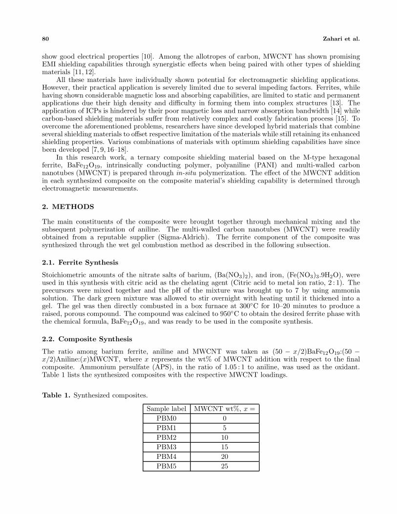
The ratio among barium ferrite, aniline and MWCNT was taken as (50 − x/2)BaFe12O19:(50 −x/2)Aniline:(x)MWCNT, where x represents the wt% of MWCNT addition with respect to the finalcomposite. Ammonium persulfate (APS), in the ratio of 1.05 : 1 to aniline, was used as the oxidant.Table 1 lists the synthesized composites with the respective MWCNT loadings.
Table 1. Synthesized composites.
Sample label MWCNT wt%, x =PBM0 0PBM1 5PBM2 10PBM3 15PBM4 20PBM5 25

Progress In Electromagnetics Research M, Vol. 52, 2016 81
Suitable amounts of BaFe12O19 and MWCNT were dispersed in 50 ml distilled water, which wasmechanically stirred for 30 minutes in an ice bath. Simultaneously, aniline, in 0.1 M of HCl, and APS,in 50 ml of distilled water, were cooled to ±3◦C in a separate ice bath. The aniline mixture was thenadded to the ferrite-CNT mixture and allowed to stir further for 30 minutes. The polymerization processwas initiated by the drop-wise addition of the APS solution to the mixture. The mixture was left tostir and reacted completely for 6 hours, while still maintaining the temperature at ±3◦C. The darkgreenish-brown compound obtained was filtered and repeatedly washed with distilled water and ethanoluntil the filtrate became colorless. It was dried in a drying oven at 80◦C overnight. The compositesynthesis was then complete and ready for characterization.
2.3. Characterization
Structural analysis was performed through x-ray diffraction (XRD) analysis by using an x-raydiffractometer (Bruker: D8 Advance XRD). The morphological aspects of the synthesized sampleswere observed through the micrographs taken by an FESEM LEO 1525, field-emission scanningelectron microscope (FESEM). The room-temperature conductivity was measured by using a 4-pointresistivity measurement system. For electromagnetic measurement purposes, the composite was mixedparaffin wax in the wt% ratio of 70 : 30 and was pressed into rectangular solids with the dimensions,22.86mm × 10.16mm × 4.5 mm. Electromagnetic parameters were measured by utilizing an AgilentTechnologies E8362B PNA Network Analyzer at the frequency range 8.2–12.4 GHz. The setup is asshown in Figure 1.
Figure 1. Electromagnetic measurement setup.
3. RESULTS AND DISCUSSION
3.1. Structural Characterization
Figure 2 shows the XRD patterns of the prepared composite samples with different MWCNT loadings.It can be easily discerned that the composite synthesis process does not result in any structural changetowards the magnetoplumbite structure of BaFe12O19 as the main characteristic peaks of the ferritematerial is still evident albeit with a decrease in its intensity. The main characteristic peaks of thesynthesized composite with the hkl indexes of (110), (017), (114), (023), (025), (026), (0 2 11) and(220), present at 2θ = 30.35◦, 32.17◦, 34.14◦, 37.11◦, 40.31◦, 42.45◦, 56.50◦ and 63.11◦, respectively,matches well to that of the BaFe12O19 standard sample (ICSD98-010-6617).
It is apparent that the increased presence of MWCNT would indirectly lead to the decreasedintensity of the main peaks attribute to the BaFe12O19. Sample PBM0 retained the intensity of theprominent peaks of the ferrite while a significant decrease in the intensity of the same characteristic

82 Zahari et al.
Figure 2. XRD analysis of composite synthesized with different MWCNT loadings and of pure PANIand MWCNT.
(a) (b)
(c) (d)
Figure 3. Micrographs of samples: (a) PBM4, (b) BaFe12O19, (c) polyaniline and (d) MWCNT takenat 50 k magnification.

Progress In Electromagnetics Research M, Vol. 52, 2016 83
peaks was seen as the MWCNT loading reaches 25wt% (PBM5). The decreasing amount of ferritecompound within the composite led to the peak intensity reduction.
Micrographs of the sample were taken through FESEM to investigate the surface morphology of thesynthesized samples. Figure 3(a) shows the micrograph of sample PBM4 alongside that of BaFe12O19
(Figure 3(b)), PANI (Figure 3(c)), and MWCNT (Figure 3(d)). Due to the nature of the ferrite synthesismethod used, BaFe12O19 particles observed in both Figures 3(a) and 3(b) are in agglomerated form withparticle sizes ranging between 60.52 nm and 457.60 nm [19]. The PANI particles are seen to form on bothBaFe12O19 and MWCNT surfaces. This is in contrast with the tubular structure normally associatedwith pure PANI when the polymerization process does not involve contact with foreign particles asshown by the structure in Figure 3(c).
3.2. Electrical Property
The conductivity, σ, of the synthesized composites was measured at room temperature by using the4-point probe technique, and the results are as shown in Table 2.
Table 2. Conductivity measurements.
Composite σ, S/mPBM0 0.1454PBM1 1.2492PBM2 1.6049PBM3 1.5839PBM4 1.8787PBM5 2.0320
The samples showed a generally increasing trend of the electrical conductivity as the MWCNTcontent within the composite was increased. The largest value of σ was observed for the sample withMWCNT wt% loading of 25% with a value of 2.0320 S/m. The good conducting nature of MWCNTresults in the improvement the overall electrical conductivity of the composite material [20].
3.3. Electromagnetic Characterization
As implied by the term, the shielding effectiveness (SE) of a material is a suitable constant to gaugethe performance of a material to shield against electromagnetic interference. SE, normally expressedin dB, is defined as the ratio between the transmitted power, Pt, and the original incident power, P0,and is given by SE (dB) = −10 log(Pt/Pi). The shielding effective can then be further expressed as thecombined effect of the shielding due to absorption, SEA, reflection, SER, and multiple reflections, SEM,which results in SE = SEA + SER + SEM. In this study, electromagnetic measurements were performedon the composites by using a two-port network analyzer and expressed in terms of the S-parameters, S11,S21, S12, and S21 which represent the reflection coefficient, R, through R = |Er/Ei|2 = |S11|2 = |S22|2,and transmission coefficient, T , through T = |Et/Ei|2 = |S21|2 = |S12|2. The absorption coefficient,A, is thus able to be defined as A = 1 − R − T. The value of A at this stage is defined with respectto the initial incident EM energy. After taking into account the reflection at the air-material interfaceand the negligible effect of multiple reflections on both material interfaces, the intensity of the EMwave propagating within the material can be defined as 1 − R which then enables the calculation ofthe effective absorbance (Aeff ), where Aeff = (1 − R − T )/(1 − R) [21, 22]. Therefore, it is possible toexpress SER and SEA as SER = −10 log(1 − R) and SEA = −10 log(1 − Aeff ) = −10 log(T/(1 − R)).
The shielding effectiveness of the different synthesized samples are illustrated in Figures 4 and 5.The values of SER for all composites show an overall decreasing trend with respect to the increasingfrequency of the electromagnetic wave. In contrast, the value of SEA is seen to increase with eachincrease in frequency. The biggest values for both shielding effectiveness constants are shown by thesample with 20wt% loading of MWCNT, PBM4, with the SER and SEA values of 5.14 dB at 8.2 GHz

84 Zahari et al.
Figure 4. Reflection loss of synthesizedcomposites.
Figure 5. Absorption loss of synthesizedcomposites.
Figure 6. Effect of different MWCNT loading towards the shielding effectiveness.
and 36.41 dB at 12.4 GHz, respectively. The lowest EMI SE values are seen in the composite without anypresence of MWCNT. The values of SER and SEA measured for sample PBM0 are 1.11 dB at 10.1 GHzand 7.72 dB at 8.2 GHz, respectively.
The effect on the different MWCNT loadings can be best summarized in Figure 6. The shieldingeffectiveness shows a similar trend for both parameters where EMI values increase with each increasein the MWCNT content with the exception of the SEA for sample PBM5 (25wt% MWCNT). Theshielding effectiveness due to absorption is lower at all measured frequency than that of sample PBM4(20wt% MWCNT). With respect to the classical electromagnetic theory, the shielding effectiveness dueto absorption can be expressed as [23]:
SEA(dB) = 20(d/δ)loge = 20d(ωμrσac/2)1/2loge (1)
where d, δ, ω, μr, σac are the shield thickness, skin depth, angular frequency, relative magneticpermeability and frequency dependent conductivity (σac = ωεoε
′′), respectively. Equation (1) showsthe dependence of the SEA on the intrinsic parameters of the material including its conductivity. Basedon the equation it was indicated that apart from the permeability, by increasing the conductivity,the shielding performance would be improved. However, it is also important to note that impedanceof materials possessing very high conductivities tends to be relatively small compared to that of air,causing a relative mismatch which results in more electromagnetic wave to be reflected back [14]. Thisexplains the slight drop of SEA and the simultaneous increase of the SER after increasing the MWCNT

Progress In Electromagnetics Research M, Vol. 52, 2016 85
loading to 25wt% from 20wt%.As the composite samples consist of materials either magnetic or dielectric in nature, it is thus
useful to determine the contribution of each constituent of the composite material in terms of anotherelectromagnetic parameter called the loss angle tangent, tan δ [24]. The magnetic loss angle tangent isdefined as tan δμ = μ′′/μ′ and the dielectric loss tangent as tan δε = ε′′/ε′. As the loss mechanism in amaterial is closely related to both imaginary components of relative permeability (μ′′) and permittivity(ε′′), a big value of loss angle tangent would imply a better electromagnetic absorption performance.The variations of the magnetic and dielectric tangential losses in each MWCNT loading with respect tofrequency are shown in Figures 7 and 8, respectively.
The initial addition of MWCNT resulted in a slight drop in the magnetic loss as observed when theMWCNT content was increased from 0 (PBM0) to 5 (PBM1) wt%. However, this trend changed withfurther increase in the MWCNT loading. Samples PBM2, PBM3, PBM4 and PBM5 showed an upwardtrend with the magnitude of the magnetic tangential loss increasing for each sample. The biggest valueof magnetic loss angle is 6.65, observed in sample PBM5 at 8.2 GHz which suggests a value of ε′′ sixtimes larger than the value of ε′.
The decreasing magnetic ferrite component alongside the simultaneous increase in the non-magneticMWCNT and PANI points towards a decrease in the magnetic tangential loss. However, the oppositehappens which can again be attributed to the increasing conductive nature of the composite as theMWCNT loading increases. A conductive material subjected to an alternating magnetic field wouldproduce an induced current that was able to dissipate energy within the material [25, 26]. The inducedcurrent is known as the eddy current loss and is one of the magnetic loss mechanisms, other than thehysteresis and residual loss.
In Figure 7, it can be seen that there exist fluctuations in the value dielectric tangential loss whenbeing taken as a function of either the MWCNT loading or the frequency especially between samples with5wt%, 10wt%, and 15wt% MWCNT loading. However, the magnitude of the losses is still significantlyhigher than that of the sample with 0wt% MWCNT. A further 5wt%-step increase in the MWCNTcontent results in a drastic increase in the magnitude of dielectric loss angle tangent. Sample PBM4shows a 4-fold increase in losses compared to the previous samples with values of dielectric loss angletangent ranging between 3 to 5, along the frequency range. It is also important to note that there existsa resonance peak at 9.36 GHz with the magnitude of loss angle reaching the value of 24.91. With theexception for loss angle tangent values recorded at frequencies lower than 9 GHz, the magnitudes of lossangle tangent for the sample with 20wt% MWCNT loading are larger than that of the other synthesizedsamples for the rest of the frequency range. Sample PBM5 with 25wt% MWCNT loading shows a slightdecrease in the tangential loss at frequencies between 9 GHz and 12.4 GHz compared to sample PBM4.
Figure 7. Magnetic loss angle tangent variationwith different MWCNT loadings with respect tofrequency.
Figure 8. Dielectric loss angle tangent variationwith different MWCNT loadings with respect tofrequency.

86 Zahari et al.
However, the existence of a resonance peak at 8.61 GHz results in the largest value of dielectric lossangle tangent recorded with the value reaching 43.24. This can be attributed to the significantly largevalue of the imaginary component of permittivity, ε′′, compared to its real counterpart, ε′.
As the electromagnetic energy loss due to absorption is the combined effects of both the dielectricand magnetic components of the synthesized composites, the algebraic sum of both tangential lossesis equal to the gross loss angle tangent [27]. The significantly big difference between the magnitudeof the dielectric and magnitude loss angle tangent observed for all synthesized samples suggests thatthe main mechanism of absorption is the dielectric losses. The introduction of MWCNT leads to theoverall increase in the electrical conductance of the material, which, combined with the conductivenature of PANI, will lead to the enhancement of loss mechanisms such as conductance and dielectriclosses [14]. However, the drop in the SEA values after the MWCNT loading reaches 25wt% suggeststhat there exists a certain threshold for the MWCNT loading which will help to enhance the absorptioncapability of the shielding material before the electromagnetic energy is reflected back. This involvesthe complex interplay between the ratio between the constituents of the composite and the intrinsicproperties (magnetic and dielectric) of said constituents.
4. CONCLUSION
The composite material consisting of BaFe12O19, MWCNT and PANI is successfully synthesized througha simple in-situ polymerization technique. XRD analysis reveals that the increasing addition ofMWCNT in the composite will result in the slight decrease in the relative intensity due to the reducedamount of crystalline ferrite in the composite. FESEM micrographs reveal that the PANI particles formon the BaFe12O19 and MWCNT surfaces and differ from their usual tubular form. Electromagneticmeasurement reveals promising values EMI shielding effectiveness especially through absorption. Theincrease in the MWCNT results in the enhanced performance of the shielding effectiveness throughabsorption. However, there exists a threshold for the MWCNT incorporation before the electromagneticwaves are reflected back resulting in decreased absorbing performance.
ACKNOWLEDGMENT
The author would like to express their gratitude toward Universiti Teknologi Petronas (UTP) andUniversiti Malaysia Perlis (UniMAP) for providing the facilities and technical support leading to thecompletion of this research work.
REFERENCES
1. Tong, X. C., Advanced Materials and Design for Electromagnetic Interference Shielding, Taylor &Francis, 2008.
2. Hibst, H., “Hexagonal ferrites from melts and aqueous solutions, magnetic recording materials,”Angewandte Chemie International Edition in English, Vol. 21, 270–282, 1982.
3. Lotgering, F. K., P. R. Locher, and R. P. van Stapele, “Anisotropy of hexagonal ferrites with M, Wand Y structures containing Fe3+ and Fe2+ as magnetic ions,” Journal of Physics and Chemistryof Solids, Vol. 41, 481–487, 1980.
4. Albanese, G., A. Deriu, and S. Rinaldi, “Sublattice magnetization and anisotropy properties ofBa3Co2Fe24O41 hexagonal ferrite,” Journal of Physics C: Solid State Physics, Vol. 9, 1313, 1976.
5. Xu, P., X. Han, and M. Wang, “Synthesis and magnetic properties of BaFe12O19 hexaferritenanoparticles by a reverse microemulsion technique,” The Journal of Physical Chemistry C,Vol. 111, 5866–5870, 2007.
6. Liu, J., P. Liu, X. Zhang, D. Pan, P. Zhang, and M. Zhang, “Synthesis and properties of singledomain sphere-shaped barium hexa-ferrite nano powders via an ultrasonic-assisted co-precipitationroute,” Ultrasonics Sonochemistry, Vol. 23, 46–52, March 2015.
7. Saini, P., V. Choudhary, B. P. Singh, R. B. Mathur, and S. K. Dhawan, “Polyaniline-MWCNTnanocomposites for microwave absorption and EMI shielding,” Materials Chemistry and Physics,Vol. 113, 919–926, 2009.

Progress In Electromagnetics Research M, Vol. 52, 2016 87
8. Duan, Y., L. Shunhua, and G. Hongtao, “Investigation of electrical conductivity andelectromagnetic shielding effectiveness of polyaniline composite,” Science and Technology ofAdvanced Materials, Vol. 6, 513–518, 2005.
9. Singh, K., A. Ohlan, V. H. Pham, B. R, S. Varshney, J. Jang, S. H. Hur, W. M. Choi, M. Kumar,S. K. Dhawan, B.-S. Kong, and J. S. Chung, “Nanostructured graphene/Fe3O4 incorporatedpolyaniline as a high performance shield against electromagnetic pollution,” Nanoscale, Vol. 5,2411–2420, 2013.
10. Sharma, B. K., N. Khare, R. Sharma, S. K. Dhawan, V. D. Vankar, and H. C. Gupta, “Dielectricbehavior of polyaniline–CNTs composite in microwave region,” Composites Science and Technology,Vol. 69, 1932–1935, 2009.
11. Han, M. and L. Deng, High Frequency Properties of Carbon Nanotubes and Their ElectromagneticWave Absorption Properties, J. M. Marulanda, Ed., Carbon Nanotubes Applications on ElectronDevices, InTech, 2011.
12. Qin, F. and C. Brosseau, “A review and analysis of microwave absorption in polymer compositesfilled with carbonaceous particles,” Journal of Applied Physics, Vol. 111, 061301, 2012.
13. Pullar, R. C., “Hexagonal ferrites: A review of the synthesis, properties and applications ofhexaferrite ceramics,” Progress in Materials Science, Vol. 57, 1191–1334, 2012.
14. Huo, J., L. Wang, and H. Yu, “Polymeric nanocomposites for electromagnetic wave absorption,”Journal of Materials Science, Vol. 44, 3917–3927, 2009.
15. Wang, Y., “Research progress on nanostructured radar absorbing materials,” Energy and PowerEngineering, Vol. 03, 580–584, 2011.
16. Tadjarodi, A., H. Kerdari, and M. Imani, “Ba0.69Sr0.17Cd0.07Zn0.07Fe12O19 nanos-trucutres/conducting polyaniline nanocomposites; synthesis, characterization and microwaveabsorption performance,” Journal of Alloys and Compounds, Vol. 554, 284–292, 2013.
17. Fan, Z., G. Luo, Z. Zhang, L. Zhou, and F. Wei, “Electromagnetic and microwave absorbingproperties of multi-walled carbon nanotubes/polymer composites,” Materials Science andEngineering: B, Vol. 132, 85–89, 2006.
18. Dhawan, S. K., K. Singh, A. K. Bakhshi, and A. Ohlan, “Conducting polymer embeddedwith nanoferrite and titanium dioxide nanoparticles for microwave absorption,” Synthetic Metals,Vol. 159, 2259–2262, 2009.
19. Goldman, A., Modern Ferrite Technology, Springer Science & Business Media, 2006.20. Bandaru, P. R., “Electrical properties and applications of carbon nanotube structures,” Journal of
Nanoscience and Nanotechnology, Vol. 7, 1239–1267, 2007.21. Phan, C. H., M. Mariatti, and Y. H. Koh, “Electromagnetic interference shielding performance of
epoxy composites filled with multiwalled carbon nanotubes/manganese zinc ferrite hybrid fillers,”Journal of Magnetism and Magnetic Materials, Vol. 401, 472–478, 2016.
22. Wang, Z., G. Wei, and G. L. Zhao, “Enhanced electromagnetic wave shielding effectiveness of Fedoped carbon nanotubes/epoxy composites,” Applied Physics Letters, Vol. 103, 183109, 2013.
23. Verma, V., J. Kapil, and N. Singh, “Structural, magnetic properties of soft and hard ferrites andtheir emi shielding application in X-band frequency range,” International Journal of EngineeringResearch & Technology (IJERT), 557–560, 2014.
24. Malek, M. F. B. A., E. M. Cheng, O. Nadiah, H. Nornikman, M. Ahmed, M. Z. A. Abdul Aziz,A. R. Othman, P. J. Soh, A. A. A.-H. Azremi, A. Hasnain, and M. N. Taib, “Rubber tire dust-ricehusk pyramidal microwave absorber,” Progress In Electromagnetics Research, Vol. 117, 449–477,2011.
25. Stoll, R. L., The Analysis of Eddy Currents, Oxford University Press, 1974.26. Pry, R. H. and C. P. Bean, “Calculation of the energy loss in magnetic sheet materials using a
domain model,” Journal of Applied Physics, Vol. 29, 532–533, 1958.27. Li, Y., Y. Huang, S. Qi, L. Niu, Y. Zhang, and Y. Wu, “Preparation, magnetic and electromagnetic
properties of polyaniline/strontium ferrite/multiwalled carbon nanotubes composite,” AppliedSurface Science, Vol. 258, 3659–3666, 2012.