emir of the state of qatar instal… · contacts: qatar general electricity & water corporation...
TRANSCRIPT

WA
TE
R IN
ST
AL
LA
TIO
NS
CO
DE
Water Installations Code CS-CSI-P1/C2
Issue : 0 16-10-2016 Unclassified
Page 03 of 67
CONTENT
Message from KAHRAMAA01 Regulation Purpose02 Building Permit03 Scope- Contacts04 Application Categories- The Law- Villas, Compounded Villas.- Multistory Buildings (Towers).- Any premises betterment. - Villa, Raw House - Malls, Commercial Centers (offices, retails, shops, Industries, etc.)- Individual villa, industrial Sector.- Commercial Sector.05 Definitions06 General- General Information for obtaining water supply.- Water Service Works / plumbing Requiring a Professional Engineer (consultant)- Water Ground Storage Capacity07 Villa, Raw House & House requirements- Water meter cabinet- Ground water tank-The water booster pumps08 Residential Compound requirements- Water Meter Service Cabinet AMR compatible- Compound Water Tanks (break tanks, each villa ground tank)- Roof plumbing- Compound internal water network- The Residential compound water booster pumps- Individual Branch water meter for flats or offices apartments09 Towers, Residential flats, Offices (High) Buildings- Main Water Meter Cabinet- Branch Water Meter Cabinet (AMR) compatible is required- Tower water demand & Multi stories building- Towers & Multi stories Buildings lifting Pumps10 Malls, Commercial Centrers (offices, retails, shops, Industries, etc.)- Main Water Meter Cabinet- Branch Water Meter Cabinet AMR compatible is required- Malls & commercial Centres total water demand required11 Fire System & Fire Meter Requirements12 Specification of Pipes and fittings Material for water network13. Specification of pipes and fitting Material for internal plumbing14. World Wide Known Quality Certification Bodies15. Customer Number Plate16. Appendix17. Water Conservation Regulations 18. Drawings & Forms19. Transport Stations20. Others
03040506
07
0811
15
17
20
22
2425263637384044
His HighnessSheikh Tameem Bin Hamad Al-Thani
Emir of the State of Qatar
WA
TE
R I
NS
TA
LL
AT
ION
S C
OD
EW
AT
ER
INS
TA
LL
AT
ION
S C
OD
EWater Installations Code CS-CSI-P1/C2Water Installations Code CS-CSI-P1/C2
Issue : 0 16-10-2016 UnclassifiedIssue : 0 16-10-2016 Unclassified
Page 05 of 67Page 04 of 67
The regulation presented in this document form part of the requirements for water services connection and installation. The purpose of this regulation is to prevent misuses, waste, undue consumption or erroneous measurement of water and most importantly, to prevent leakage of potable water. These regulations would replace the former Rules and Regulation Guide Plumbing works, the previous additions 2006, 2007 and May 2009.
General Guidelines for Updating KM “Regulations of Internal Water Installations and Connection Works”
1. Review and update the existing regulations in compliance with the up-to-date international standards such as IEC, BS, ASHARE, etc. and the industry best practices.
2. Recommend new regulations where applicable or necessary for high-rise buildings for internal
water installations.
3. Develop water connection works (internal installations, risers, internal water networks, etc.) guidelines for large scale developments such as malls, residential buildings, high-rise towers, etc.
4. Revise existing regulations wherever necessary and/or include new clauses in applicable sectors to accommodate conservation of electricity and water.
5. Revise existing regulations to include water quality standards in customer premises, and corrective/ preventive measures.
6. Recommend new specifications for remote metering reading, relevant to smart meter technical specifications, operation systems, installations, and/or all other aspects that are related to the concept of remote meter reading and control.
7. Provide recommendations regarding relation of internal water installations works and Qatar Civil Defence requirements based on the latest international / particular standards in this regard.
1. Regulation PurposeMessage from KAHRAMAA
Dear Consultants, Contractors and Valuable Customers,
Qatar General Electricity and Water Corporation “KAHRAMAA” is committed as per its mission “To provide our customers with high quality electricity and water services, whilst creating value of our shareholders”, based on customer services Department mission to provide customers with high safe and secure water installation.
The Customer Services Department (CSD) would like to present the book of (Regulation of Internal Water Installations and Connection Works).
As part of the Customer Services Department effort to facilitate communications, the book can be downloaded from KAHRAMAA website http://www.km.com.qa.
The book is the only approved reference book approved by KAHRAMAA and from now on all updates and upgrades of the installation regulations book will be available on KAHRAMAA website.
In this case, KAHRAMAA reserves its right to update and upgrade the book of Regulation of Internal Water Installation and Connections Works without prior notice.
Kind Regards,
Engineer Yousef Ahmed Al Jaidah Manager of Customer Services Department Qatar General Electricity and Water Corporation “KAHRAMAA”
KAHRAMAACustomer Services Department Customer Installation Section Tel +974 4462 8559Fax +974 4462 8294http:// www.km.com.qa

WA
TE
R I
NS
TA
LL
AT
ION
S C
OD
EW
AT
ER
INS
TA
LL
AT
ION
S C
OD
EWater Installations Code CS-CSI-P1/C2Water Installations Code CS-CSI-P1/C2
Issue : 0 16-10-2016 UnclassifiedIssue : 0 16-10-2016 Unclassified
Page 07 of 67Page 06 of 67
The scope of KAHRAMAA water Regulation for Consultants, Contractors and Valuable customers.
Qatar General Electricity and Water Corporation “KAHRAMAA” is committed as per its mission “To provide our customers with high quality electricity and water services, whilst creating value of our shareholders”, based on Customer Services Department mission to provide customers with high safe and secure water installation.
Scope for KAHRAMAA Consultant:
• Experiment this regulation with positive vetting with SI standard.
• Benchmarking jurisdiction with British Standards relevant to the State of Qatar or GCC standards avoiding inveterate.
• Cognate jurisdiction with SI standard resemblance, further with the American Standard with GCC particular standard.
• KAHRAMAA particular jurisdiction blossom and consolidate enhancement and expectation via AMR system.
• Objectives are enhancement, accreditation with all relevant expectation to hire proper water service decontamination, conservative, dumping, decreasing water loss via KAHRAMAA target proper continuous water supply.
Contacts:
Qatar General Electricity & Water Corporation (KAHRAMAA). Customer Services Department, Tel: 44628282 / 44628559 Building Permit Complex - Doha, Tel: 49505050 Website: www.kahramaa.com.qa
3. Scope2. Building Permit
“All Building Permit Applications are Electronically Applied through BP Application System. In order to be reviewed by KM Engineers in accordance to KM regulation and specifications.”
In order to be reviewed by Installation Section Engineers due to KAHRAMAA regulation and specifications.
WA
TE
R I
NS
TA
LL
AT
ION
S C
OD
EW
AT
ER
INS
TA
LL
AT
ION
S C
OD
EWater Installations Code CS-CSI-P1/C2Water Installations Code CS-CSI-P1/C2
Issue : 0 16-10-2016 UnclassifiedIssue : 0 16-10-2016 Unclassified
Page 09 of 67Page 08 of 67
In this by laws booklet, the following words and expressions shall have the meanings defined as follows:
Applicant: A person who is of a communal service.
Approval or Approved: Approval in writing or stamp by KAHRAMAA.
AMI: Advance Meter Infrastructure for the AMR.
AMR: Automatic Meter Reading system for remote reading.
Back Flow: The flow in a direction contrary to the intended normal direction of flow.
Branch meters: All sub meters that supply different apartments in the residential buildings, villa compounds, retails, shops inside malls or commercial centres.
Bulk Customer: The customer who has demand exceeding 600m3 per day.
Customer: Any person, persons or corporate body supplied with, or applying to be supplied with water by KAHRAMAA. Reference to “Customer” in these by laws shall include applicant as previously defined.
Customer Premises: Property land which the owner has a deed for such as villa, house, building, etc.
Corrosion Resisting Material: Any material which is highly resistant to any corrosive action to which it is likely to be subjected in the circumstances in which it is to be used.
Cylinder: Cylindrical closed vessel capable of containing water under pressure greater than atmospheric pressure.
Capacity in relation to Storage Water Tank or Tank: The capacity of the Water Tank or tank measured to the highest level that water can reach when the float valve or other approved device for controlling the inflow of water is fitted.
Charge: Any charge for water, any deposit or fees payable to the KAHRAMAA, the actual cost or other works carried out by the KAHRAMAA, and any other charge including any surcharge which is payable under these by laws.
Water Tank: A fixed container for holding water at atmospheric pressure such as tanks, sectional panel GRP tank or concrete tank.
Closed Loop: Any system of pipes and water fittings through which water circulates in the internal network (in Residential Complex) and from which water is drawn for use, that feeds or supplies water to the Water Tank.
Distributing Pipe: Any pipe (other than an overflow or a flushing pipe) conveying water from a storage
Water Tank or from a hot water apparatus supplied from a feed Water Tank, or under pressure from that Water Tank.
5. Definitions
The Law Prior to starting any installation activities related to services connection or installation to the following
development, the applicant must submit preliminary design drawings attached with the building permit application to KAHRAMAA, Customer Services Department for review and subsequent approval.
• Villa, Raw House
• Towers, Residential flats, Offices (High) Buildings
• Any premises betterment.
• Residential Compound
• Malls, Retails & Commercial Centres.
• Individual villa & Industrial sector.
• Commercial sector.
4.1 Document Required for Water Service Connection
Contractor should submit their request online KMSP• Submit a photo copy of installed service cabinet.
• Submit a photo copy of owning-ship document.
• Submit Photo Copy of Service Site Plan with Proper Coordinates of Meter & Connection Location requiring New Connection, Re-location and Etc.
• Submit a photo copy of the State of Qatar ID card.
• Submit a photo copy of Company Registration Number.
• Submit electricity number.
• Submit building permit approval.
• Submit Valid Holding Certificate and No Objection Certificate from Agricultural Affairs for Water Supply to Farms.
4.2 Document Required for Temporary Water Supply
Contractor should submit their request online KMSP• Submit building permit approval.
• Submit a photo copy of site plan.
• Complete all installation requirements and coordinate with Customer Services Department Installation Engineer.
4.3 Upgrading of Water Supply:• Daily Demand.
• Tank Capacity.
• WEMS Report.
• Existing Service Connection Size.
4. Application Categories
WA
TE
R I
NS
TA
LL
AT
ION
S C
OD
EW
AT
ER
INS
TA
LL
AT
ION
S C
OD
EWater Installations Code CS-CSI-P1/C2Water Installations Code CS-CSI-P1/C2
Issue : 0 16-10-2016 UnclassifiedIssue : 0 16-10-2016 Unclassified
Page 11 of 67Page 10 of 67
PRV: Pressure Reducing Valve that regulates the flow of the appropriate pressure.
NRV: Non Return Valve to avoid backflow from pressurized source.
FCV: Flow Control Valve to regulate the flow and pressure the pipe system/customer.
Riser: The pipe that conveys water from downstream of a booster pump up to the roof tanks on the roof floor of the building.
Registered Plumbing Contractor: A person authorized by the KAHRAMAA, to carry out plumbing work of the grade indicated.
Sub Main: Water meters inside the compound (complex), through which water is conveyed to the buildings from the internal network inside the complex, in case of complex composed of villa and buildings.
Sub Meters: Individual meters downstream of the main meter or sub main through which water is conveyed to flats or villas in a building or complex. Service Pipe: Any pipe / arrangement of pipes for supplying water from a distribution main to any premises as it is subject to water pressure from that main and ends at the water meter at the customer’s boundary provided that only one pipe can be connected to the water meter.
Service Connection: The part of pipes and fittings between the distribution mains up to and including the water meter at the customer’s boundary.
Spill Over Level: The level at which the water in a Water Tank or vessel will first spill over if the inflow exceeds the outflow through any outlet and any overflow pipe.
Stop Valve: Any device other than a draw off tap for stopping the flow of water in a pipe. Sub Main meter: Meter install for each building inside the residential compound as tapping from compound’s internal water network.
Swimming Pool Plant Room: The mechanical room for a swimming pool in which filtration, dosing and circulation of water is done through the surge or balance tank.
Stoppage Tank: Any tank other than a flushing Water Tank having a free water surface under atmospheric pressure, but does not include a drinking trough or drinking bowl for animals including poultry.
Water Booster Pumps: A set of pumps that boosts water from the main Water Tank to the villa or flat utilities. It is very important to detect the pump’s total head and the height of the premises and relevant losses.
Warning Pipe: An overflow fixed to its outlet, whether inside or outside the building, so it is in a conspicuous position where the discharge of water can be readily seen.
Water Installation Works: all plumbing works within the owner premises.
Distributing Main: A pipeline that conveys water to the premises by means of service connection.
Domestic Water System: The water system which includes the distributing pipe and all associated apparatus within premises, up to the point where water is drawn for use.
Fire Service: The pipes, tanks, pumps, fittings and apparatus in any premises installed for the purpose of firefighting.
Flot Valve: A valve for controlling the flow of water into a Water Tank, the valve being operated by the vertical movement of a float riding on the surface of the water.
Flushing Water Tank: A Water Tank provided with its discharging apparatus for discharging the stored water rapidly into a water closet pan, urinal, drain or sewer.
Header: The pipe conveying water from the downstream tank or roof tank in building through OTS (Open To Sky) supplying the corresponding floor.
Inside Service: The pipes and fittings in premises after the ground storage tank and any pipes and fittings between the storage tanks and the termination of the water network service connection, which shall normally be at the meter.
Insulating tubes: All roof plumbing tubes / pipes and fittings should be heat insulated using materials which are poor conductors of heat (Fibrous material or Cellular material) with Aluminium cladding that protects thermal block tubes from direct sun radiation.
ISO: The International Organization for Standardization.
Internal Network: A pipeline that conveys water from the main Water Tank to the individual villa or buildings and other utilities inside the residential complex by the set of water pumps.
Meter: Any appliance or device owned and maintained by KAHRAMAA for the purpose of measuring consumption.
Main Meter: A meter where the water is conveyed from the distribution network to the premises through it to the adjacent ground tanks.
Meter Cabinet: The Meter Cabinet will be as per KAHRAMA Standards and Specifications.
Meter Chamber: The manhole underground in which the electronic sensor will be installed and connected to the GRP bulk meter cabinet by 2 inches conducted to the sensor cord to the EDU (Electronic Display Unit).
Over Flow Level: The lowest level at which water can flow in to the overflow pipe of a Water Tank or tank.
Potable Water: Water supplied by KAHRAMAA which is suitable for drinking and culinary purposes.
Premises: Any land, house, building, possessed or reverted to the owner. A house, building, apartment or part of a house and the cartilage thereof in respect of which water is supplied or applied for.
WA
TE
R I
NS
TA
LL
AT
ION
S C
OD
EW
AT
ER
INS
TA
LL
AT
ION
S C
OD
EWater Installations Code CS-CSI-P1/C2Water Installations Code CS-CSI-P1/C2
Issue : 0 16-10-2016 UnclassifiedIssue : 0 16-10-2016 Unclassified
Page 13 of 67Page 12 of 67
6.2.3 Inspections by KAHRAMAA Inspectors The KAHRAMAA inspector will carry out checks on completed water service installation on a
premises. Where the water service installation is found not to be in compliance with the requirements specified, KAHRAMAA will require the water service owner, developer or customer to alter, repair or rectify the water service installation.
6.2.4 Developers / customers applying for water service supply to their private property / project development need a completion certificate and will pay a connection fee, depending on the size of connection to the development. The connecting pipe will then be laid from KAHRAMAA water mains to the meter service cabinet after the payment is made.
6.2.5 Annual Inspection and Cleaning of Water Storage Tanks
For any part of a water service installation having any water storage tank from which water for human consumption is drawn in residential premises, the customer has to do the necessary maintenance and clean the storage tanks annually. The water service installation is required to ensure that:
1. The storage tank (including any tap fitted to the storage tank) and its ancillary equipment.
2. The premises where the storage tank and its ancillary equipment are located and are kept properly locked at all times.
3. Checks are conducted regularly for the purpose of ascertaining (including any tap fitted to the storage tank) or its ancillary equipment which comes to his knowledge.
6.3 Water Ground 6.3.1 Water Ground Tank / Break Tank Capacity
Considerations affect the storage capacity:
1. The number of customers.
2. The type of building.
3. The fitting size to be served.
The ground storage tank capacity should be sufficient for 2 days of water demand.
Each case should be judged based on its properties, but for general guidance, the following table should be used in calculating the water demand during the design.
6.3.2 Water Ground Tank Type
• the Ground Water Tank should not exceed a distance of 5 meters from the Flow Meter Cabinet/Chamber, otherwise a break is required.
• All tanks should be provided with an overflow pipe connected to the discharge line.
• The ground water tank/ break tank could be above or under the ground. For the above ground tank, the inlet height should not exceed 3 m. for the underground tank, the inlet should be with FCV (float control valve)
6.4 Buffer/Break Tank (See the word file for this point and the above)The compound main break should be implemented in case the distance between ground tank and
6.1 General Information for Obtaining Water Supply
6.1.1 Simplified Procedure
Under the simplified procedure introduced for the design and installation of water service installations within the customers premises, water service workers have full control over the water
service works under their charge and due to KAHRAMAA jurisdiction.
In brief, the procedure requires the water service to notify KAHRAMAA before commencement of water service works by submitting all plumbing drawings like site plans and schematic drawings of the water service installation. Upon completion of the water service works, the service work certifies that the water service installation is completed in accordance with KAHRAMAA Water Supply Regulations.
6.1.2 Water Service Work
Water service work plumbing shall only be carried out due to KAHRAMAA water service jurisdiction of an appropriate class as prescribed by the latest edition of this KAHRAMAA Water Supply Regulations. The developer / customer shall engage an appropriate water service works by consultant to design, construct, alter or repair at his own cost the water service installation within his premises to convey the supply of water from KAHRAMAA water networks.
6.2 Water Service Works / Plumbing Requires a Professional Engineer (Consultant) 6.2.1 KAHRAMAA Customers Services Department decisions are mandatory requirements for
implementation in the above mentioned project during execution. The applicant at this stage is exposed to these obligations for the implementation of the project.
All materials for services connection such as pipes & fittings, electronic water meter, water meter cabinet, etc. shall be subject to and comply with the latest edition of KAHRAMAA general specification of main lying of materials.
Materials used in direct connection with potable water services connection must comply with the International Standards (ISO, BS, EN, DIN). These standards have a set of specifications for the materials usage.
Any material used in direct contact with potable water, that cause or are likely to cause contamination to potable water in service renewal, repair or replacement, which conveys or receives water supplied for domestic or food production purposes, should be disinfected and sterilized prior to such connection. Moreover, all materials to be used in contact with potable water must have a health certificate issued by credited and approved by kahramaa world wide known quality body certifier (such as one of the following listed in this Regulation).
6.2.2 Seeking Water Service
When all water service works are completed, the customer / owner will need to apply for water supply at the Customer Services Department for the installation of water service to the premises.
6. General
WA
TE
R I
NS
TA
LL
AT
ION
S C
OD
EW
AT
ER
INS
TA
LL
AT
ION
S C
OD
EWater Installations Code CS-CSI-P1/C2Water Installations Code CS-CSI-P1/C2
Issue : 0 16-10-2016 UnclassifiedIssue : 0 16-10-2016 Unclassified
Page 15 of 67Page 14 of 67
6.5 Roof Tank
• The roof tank should be under shade or shelter for conservation, and protected for direct sun radiation.
• the compound main break should be implemented in case the distance between ground tank and meter cabinet/ chamber more than 5 m
• the capacity of the main break tank should be ¼ of the total ground tanks
6.6 Roof Plumbing
• All pipes and fittings materials as per Kahramaa aproval list should be thermal heat insulated by insulating materials. Materials used should be non conductive of heat (Fibrous material or Cellular material) with Aluminium cladding to protect and thermal block from direct sun radiation.
Note: The above two points will be applied to all application categories.
6.7 Water Meter Cabinet
• The Water Meter Cabinet is required for Water Meter with size ranging from Ø22mm to Ø54mm and should be compatible with the AMR System.
• Service cabinet must be installed on the boundary wall to the nearest point to KAHRAMAA water networks either in front of the premises or at the back of it.
• The service pipe internal diameter size must be refer to drawings NDS-SD-220A, NDS-SD-220B, NDS-SD-220C.
• The service pipe line must be embedded and installed at height 1.1 m. from the ground level (road level). (220 drawings to be add)
• Bottom of the embedded water service cabinet must be 80 mm PVC duct embedded in the wall until 0.3 m of the road level ending with 45 degrees, 80 mm PVC elbow.
• The gate valve must be installed indoors between the cabinet and the ground tank ball valve, and all fittings should be soldered.
• Water service cabinet design and specification figure No. (CSD-CSI-01-2011)
• Break tank “: Water meter cabinet should be adjacent to the plot boundary and ground water tank / break water tank should not exceed a distance of 5 meters from the Meter Cabinet
6.8 Legislation
Each building or facility could be supplied by one connection to the water network. Additional connections if necessary and deemed required for technical reasons are possible subject to concerned department approval
Land Use Category Unit Daily Water Consumption (Litres)
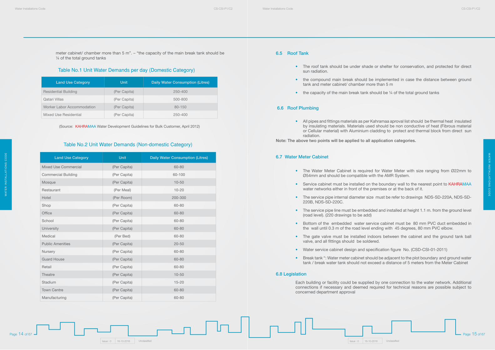
Mixed Use Commercial (Per Capita) 60-80
Commercial Building (Per Capita) 60-100
Mosque (Per Capita) 10-50
Restaurant (Per Meal) 10-20
Hotel (Per Room) 200-300
Shop (Per Capita) 60-80
Office (Per Capita) 60-80
School (Per Capita) 60-80
University (Per Capita) 60-80
Medical (Per Bed) 60-80
Public Amenities (Per Capita) 20-50
Nursery (Per Capita) 60-80
Guard House (Per Capita) 60-80
Retail (Per Capita) 60-80
Theatre (Per Capita) 10-50
Stadium (Per Capita) 15-20
Town Centre (Per Capita) 60-80
Manufacturing (Per Capita) 60-80
Table No.2 Unit Water Demands (Non-domestic Category)
Table No.1 Unit Water Demands per day (Domestic Category)
Land Use Category Unit Daily Water Consumption (Litres)
Residential Building (Per Capita) 250-400
Qatari Villas (Per Capita) 500-800
Worker Labor Accommodation (Per Capita) 80-150
Mixed Use Residential (Per Capita) 250-400
(Source: KAHRAMAA Water Development Guidelines for Bulk Customer, April 2012)
meter cabinet/ chamber more than 5 m”. – “the capacity of the main break tank should be ¼ of the total ground tanks
WA
TE
R I
NS
TA
LL
AT
ION
S C
OD
EW
AT
ER
INS
TA
LL
AT
ION
S C
OD
EWater Installations Code CS-CSI-P1/C2Water Installations Code CS-CSI-P1/C2
Issue : 0 16-10-2016 UnclassifiedIssue : 0 16-10-2016 Unclassified
Page 17 of 67Page 16 of 67
Roof Tank Should be minimum (600 US gal or 2.3 m3) for public house or villa and other utilities building
(guard room).
7.2 The Water Booster Pumps
• Water pump is required for boosting and conveying the water from the ground water tank to the roof water.
• All the pumps must be automatic with floating switch on (low level or high level switch).
• Water pump must be set under the maximum pressure not exceeding 3 bar or 43 PSI.
• Water pump total head should be more than 20m per head for two story buildings. Others should be decided by the designer.
7.1 Ground Water Tank:
The Water Tank that holds the ultimate demand - including domestic or others.
• For Villa, Row House, Public House, Ground Water Tank is required and its capacity should be minimum 2000 US gal or 7.6 m³.
• In case of more than 7 persons, additional capacity of 85 US gallons (320 Litres) x no. of persons is required.
• The ground water capacity should be sufficient for 2 days of water demand.
• In case of villa or public house, that uses pressurized system, the ground tanks must be sufficient for relevant high consumption.
• In case of public house or villa they may have ground tanks and roof tanks.
• In case of villa with slope roof floor or gable, and workshops, the roof tank must be installed in steel stand to elevate the tank. See figure (CSD – CSI – 09 -01) will emanate the installation.
• In case of agricultural surfaces and swimming pools, it is recommended to require an extra ground storage tank which will be utilized as a separate tank for domestic ground reservoir.
• In case of mixed commercial / residential properties, separate ground / roof tanks should be provided for residential and commercials and each ground tank capacity should be sufficient for 2 days of water demand.
• The water booster pump must be installed in a legal position downstream (outlet discharge point from that tank) with a non-return valve (one directional valve) then conveyance water towards roof tank.
• Ground Water Tank should not exceed a distance of 5 meters from the Flow Meter Cabinet/Chamber, otherwise a break is required.
• Service duct should be laid for M-Bus cabling from the water meter to the electrical meter. Service duct should be HDPE with the inner diameter of 32mm.
7. Villa, Raw House & House Requirements

WA
TE
R I
NS
TA
LL
AT
ION
S C
OD
EW
AT
ER
INS
TA
LL
AT
ION
S C
OD
EWater Installations Code CS-CSI-P1/C2Water Installations Code CS-CSI-P1/C2
Issue : 0 16-10-2016 UnclassifiedIssue : 0 16-10-2016 Unclassified
Page 19 of 67Page 18 of 67
• The compound main break tanks will be 1/4 of the total compound ground tanks demand if each separate villa in the compound has its ground tank. See figure (House Complex Drawing. no. 2) will emanate the installation
• Sectional Panel GRP Tank: Must be as per KAHRAMAA specifications. This tank must hold the design proposal water demand as shown table No.1 and 2. This tank should submit with all the relevant requirements in drawings at the building permit stage in the location and capacity on the appropriate 0.30m concrete plinth.
• Concreter Tank either underground or above the ground: Must be constructed due to “QCS” latest edition. The utilization of epoxy coated reinforce steel bar, in accordance with the specification, with commensurate water demand, requires the ventilation, GRP ladder and manhole cover exposed 0.10m above the floor level. To avoid the surface water entries. See figure (NDS – SD – 217A) will emanate the installation.
8.3 Compound Internal Water Network:
The internal water network inside the compound:
• Internal water network should be laid in only one side of the service road inside the compound.
• Pipes should be as per Kahramaa aproval material list with the inner diameter (80mm,100 or 150mm).
• Pipes should be laid in 0.90m as per kahramma standard drawings (221). 0.20m sand dune is required as base for the network pipes. Further, 0.30m backfill of the sand dune over the network pipes.
• Internal water network pipe should be on the other side of the sewerage network pipes to avoid the contamination.
• All tapping for branch service connection inside the compound should be from the internal water network, by using gunmetal ferrule (gunmetal refer to BS 1400 - LG2), for each service connection. See (DRG.no. NDS/SD/220B).
• Network controle valves should be gate vales, For 100-300mm-dia. pipes, use Sluice Valves; for 400-mm dia. & above: use Butterfly Valves. For 100-300mm Sluice valves: use Valve boxes (KM drawing NDS-SD- 230 Rev-01) and for 400mm- dia. & Above Butterfly Valves: use chambers
• At the service connection stage, the internal network should be inspected before the embankment of the compound internal network.
• The hydro test: The pressure test should reach 6 bar.
• Trench marker tape for all material approved by KM pipes should be laid in 0.5 m on top of water pipes
• Pipes should be laid in 0.90m depth of the road level. 0.20m sand dune is required as base of the network pipes. Further, 0.30m backfill of the sand dune over the network pipes: As per KM standards & Specifications, please refer to KM Standard drawing, NDS-SD-221
• All road crossing SC is to be provided with 150 upvc service duct as per the drawing number NDS-SD-17B- reinstatement- Rev- f
Residential compound could be one of two types:
• Pure villa compound. See figure (Housing Complex Drawing. Nos. 1 And 2)
• Combined villa & building compounds. See figure (Building Complex) or of villa and buildings, this will emanate the installation.
8.1 Water Meter Service Cabinet AMR compatible:
• Meter chamber is required in case of tie in point to the residential compound, its internal diameter should be 80mm or more, the water meter chamber is required. See figure (NDS / SD / 133).
• All tapping for branch service connection inside the compound should be from the internal water network, by using gun metal ferrule for each service connection. See (DRG.no. NDS/SD/220B).
• Villa, Raw House & House Requirements:
Service duct should be laid for M-Bus cabling from the water meter to the electrical meter. Service duct should be HDPE with the inner diameter of 32mm.
• Towers, Residential flats requirements:
Service duct should be laid for M-Bus cabling from the water meter to Main Electric (LV) Room. Service duct should be HDPE with the inner diameter of 32mm.
8.2 Compound Water Tanks (break tanks, individual villa ground tanks):
8.2.1 The villa compound water tanks requirements:
Individual villas in a compound:
• The main ground reservoir capacity should be minimum (2000 US gal).
• In case of more than 7 persons, additional capacity of 85 US gallons (320 Litres) x no. of persons is required.
• Water tank must be on concrete base 0.2m thick.
• The supply inlet point to water tank must be on top of the water tank with ball valve. See figure (House Complex Drawing. no. 1) will emanate the installation.
• The water booster pumps should be fixed legally on the downstream discharge points from water tank.
• Each villa should have a roof tank with minimum capacity (600 US gal or 2.3 m3) using the gravity as power conservation system.
• Ground Water Tank should not exceed a distance of 5 meters from the Flow Meter Cabinet/Chamber, otherwise a break is required.
8. Residential Compound Requirements
WA
TE
R I
NS
TA
LL
AT
ION
S C
OD
EW
AT
ER
INS
TA
LL
AT
ION
S C
OD
EWater Installations Code CS-CSI-P1/C2Water Installations Code CS-CSI-P1/C2
Issue : 0 16-10-2016 UnclassifiedIssue : 0 16-10-2016 Unclassified
Page 21 of 67Page 20 of 67
For residential multi stories buildings, tenement and towers requirements:
• All individual apartments, flats, offices and retail, should have a separate water meter installed on the same floor in an approved branch meter cabinet, AMR compatible.
• Citation in all relevant drawings submitted by consultant e.g. Schematic Diagram for over all buildings showing the 22mm branch water meters should be in each floor.
• All branch water meters should be installed in the approved branch meters cabinet AMR compatible. See fig. (CSD - CSI - 2 - 2012) will emanate the installation.
• The consultant must determine the location of sub meter to be closer to OTS duct (Open To Sky) through which the 100mm discharge header is pass through.
• Allusion by consultant must consider the individual meter cabinets to be in suitable location e.g. corridor for easy monitoring and handling (at 100mm from the finish floor level).
• Clear citation of the pressure reducing valve in each floor taping before the corresponding individual sub meters must be set less or equal to 3 Bar or 42 PSI for meter accuracy. See figure (CSD - CSI - 2 - 2012) will emanate the installation.
• Non Return Valve is required downstream of the proposed meter to be installed. See figure (CSD – CSI – 2 – 2012) will emanate the installation.
• Drain is required at the bottom of the cabinet conveying water to OTS Duct.
9.1 Main Water Meter Cabinet:
• Approved water meter cabinet (AMR compatible) is required for the service connection (54mm).
• It must be installed and embedded in the boundary wall of the plot or premises adjacent to KAHRAMAA water main. This should be mentioned in the drawing Service Site Plan (SSP) water layout in building permit stage.
• In case of large diameter water service connection required, the meter chamber must be constructed at the approved drawings BP (Building Permit) stage. See figure (NDS / SD / 133) will emanate the installation.
• Service duct should be laid for M-Bus cabling from the water meter to Main Electric (LV) Room. Service duct should be HDPE with the inner diameter of 32mm.
9.2 Branch Water Meter Cabinet (AMR) compatible is required:
• Branch meters orientation should be installed in each floor with 32mm PVC conduit with nylon robe from the branch meter cabinet AMR compatible. See figure (CSD - CSI - 2 - 2012) will emanate the installation.
• The pipe inside cabinet should be brass to install meter (sizes: 22mm-42mm)
9. High Buildings: Towers, Residential flats and Offices Requirements
8.4 The residential compound water booster pumps:• Set of 3 water pumps are required for boosting and conveying the water from the main
water tanks into the internal water network.
• All the pumps must be automatic with the pressurized system to switch on.
• All pumps must be set under the maximum pressure not exceeding 3 bar or 43 PSI.
• Selection of water pumps should be with the sufficient total head.
8.5 Individual branch water meter for flats, offices or apartments:• Water meters can be installed in each floor for all flats or apartments in dwelling buildings,
moreover inside the combined residential compound.
• Branch water meters can be installed on the roof under the below conditions:
1. Should offer 24 hours accessibility to enter the roof for monitoring maintenance meters.
2. Minimum 2 roof tanks should be above the stair case. The downstream discharge header should be minimum 80mm tube.
3. Those meters should be installed vertically and embedded on a small wall 2.0m in height.
4. The bottom of the cabinets should be steel trench that protects all plumbing.
• Each villa, club house, guard house and any other utilities buildings inside the compound should have a separate meter in an approved service cabinet. See figure (CSD – CSI – 1 – 2012) and (CSD – CSI – 2 – 2012) will emanate the installation. At 1.0m bottom edges high form the compound road level.
• Flats or apartment should have a separate water meter in an approved branch water cabinet. See fig. ( CSD – CSI – 2 – 2012) will emanate the installation.
• Sub main meter required for each building inside the combined compound meter should be in the approved meter cabinet compatible with the AMR system.
WA
TE
R I
NS
TA
LL
AT
ION
S C
OD
EW
AT
ER
INS
TA
LL
AT
ION
S C
OD
EWater Installations Code CS-CSI-P1/C2Water Installations Code CS-CSI-P1/C2
Issue : 0 16-10-2016 UnclassifiedIssue : 0 16-10-2016 Unclassified
Page 23 of 67Page 22 of 67
10.1 Main Water Meter Cabinet:
• Approved water meter cabinet (AMR compatible) is required for the main service connection.
• It must be installed and embedded in the boundary wall of the plot or premises adjacent to KAHRAMAA water main. This should be mentioned in the drawing Service Site Plan (SSP) water layout at the building permit stage.
• In case of large diameter water service connection required, the meter chamber must be constructed at the approved drawings BP (Building Permit) stage. as in figure (GIS / STD / 52 - 06A) will emanate the installation.
• Service duct should be laid for M-Bus cabling from the water meter to Main Electric (LV) Room. Service duct should be HDPE with the inner diameter of 32mm.
10.2 Branch Water Meter Cabinet AMR compatible is required:
• Branch meters orientation can be installed in each floor with 32mm PVC conduit with nylon robe from the branch meter cabinet AMR compatible. See fig. (CSD - CSI - 2 - 2012) will emanate the installation.
• Branch water meters could be install on the roof under the below conditions:
1. Should offer 24 hours accessibility to enter the roof for monitoring maintenance meters.
2. Minimum 2 roof tanks should be above the stair case with header minimum 80mm.
3. Those meters should be installed vertically and embedded on a small wall 2.0m in height.
4. The bottom of the cabinets should be steel trench that protects all plumbing.
• Required water in the Mall (each shop, retail, office... etc.) should have a separate water meter installed in on each floor inside the approved branch meter cabinet, AMR compatible See fig. (CSD – CSI – 2 – 2012).
• The branch meter cabinet (AMR compatible) should be installed 1.0m above the floor level. The branch meter cabinet should be embedded in the wall.
10.3 Malls & commercial centres total water demand required:
• The total demand for total number of retails, shops, offices is 400 US gal or (1.5 m3) each. There should be sufficient tank for 2 days.
• The total demand should be calculated as table 1,2 (page) should be in the ground tank capacity.
• 400 US gal or 1.5m3 x total number of retails, shops, offices…etc.
• The ground tank or reservoir that holds the total demand is calculated as mentioned above. See table 1,2 (page) .
• This ground tank could be in the ground floor or basement.
• This reservoir or tank that holds the total demand can be regular PE water tanks, sectional panel GRP, concrete tanks or tanks. See figure (NDS - SD – 217A).
10. Malls, Commercial centres (offices, retails, shops, Industrials,etc.)
Requirements.
• Each flat, apartment, retail and office should have separate water meters installed on each floor, inside the approved branch meter cabinet, AMR compatible. See figure. (CSD – CSI – 2 – 2012)
• The branch meter cabinet should be installed 1.0m above the floor level. The branch meter cabinet should be embedded in the wall.
• Branch water meters can be installed on the roof under the below conditions:
1. Should offer 24 hours accessibility to enter the roof for monitoring maintenance meters.
2. Minimum 2 roof tanks should be above the stair case with header minimum 80mm.
3. Those meters should be installed vertically and embedded on a small wall 2.0m in height.
4. The bottom of the cabinets should be steel trench that protects all plumbing.
9.3 Towers & multi story buildings water demand:
• The total demand for all flats and apartments is 500 US gal or 1.9 cubic meter and should be sufficient for 2 days.
• The total demand should be calculated and should be in the ground tank capacity.
• 500 US gal or (1.9m3) x total number of flats or apartments.
• The ground tank or reservoir that holds this total demand is calculated as mentioned above -this ground tank can be in the ground floor or basement.
• This reservoir or tank that holds the total demand can be a regular PE tank, a concrete tank or a sectional panel GRP tank.
• Water ground reservoir can be an approved tank, a sectional panel GRP tank or underground concrete tank. See figure (NDS-SD-217A), citation of this total demand should be made clear at the BP stage to be revised by CSD engineer.
9.4 Towers & multi stories buildings lifting pumps:
• Determine the proposal pump total head, foregoing your set of pumps total head that requires conveying the domestic water via the roof tanks.
• Determine the lifting pump total head that exceeds the tower’s height, otherwise the break tanks at suitable floor is required, until it reaches the tower roof floor and conveys water by gravity to all apartments / fats / offices.
• This to be allusive clearly in water schematic diagram submitted at the BP stage.
WA
TE
R I
NS
TA
LL
AT
ION
S C
OD
EW
AT
ER
INS
TA
LL
AT
ION
S C
OD
EWater Installations Code CS-CSI-P1/C2Water Installations Code CS-CSI-P1/C2
Issue : 0 16-10-2016 UnclassifiedIssue : 0 16-10-2016 Unclassified
Page 25 of 67Page 24 of 67
Fire systems used in buildings are usually either a sprinkler system type or a hose reel type - this will be authorized by CDD.
• A water meter is required for a fire system, upstream of the fire, if there is a separate water tank.
• A fire system inside a residential complex will be approved by CDD, but if there is a separate fire water tank, the water meter is required upstream of the tank.
• Water tanks and water demand required for fire, must be considered in calculation with the domestic demand.
• In case of separate fire tanks for the fire system in the building, the fire water meter will be installed upstream of the tanks.
• Fire system supply from the combined water reservoir; In case of combined water tanks, the fire meter should be installed down steam, within 1.5m spool pipe far from the fire water pumps.
• This should be clearly mentioned in the submitted drawings, and mentioned clearly in the water schematic diagram at the Building Permit stage, in order to be revised by CSD authorized engineers.
11. Fire system & Fire meter Requirements
• we propose to add: Ground Water Tank should not exceed a distance of 5 meters from the Flow Meter Cabinet/Chamber, otherwise a break is required.
• Water ground reservoir can be PE tanks, a sectional panel GRP tank or underground concrete tanks. See figure (CSD-09-04) / (NDS - SD – 217A) The citation of this total demand with all relevant drawings should be submitted at the BP stage to be revised by CSD engineer.
WA
TE
R I
NS
TA
LL
AT
ION
S C
OD
EW
AT
ER
INS
TA
LL
AT
ION
S C
OD
EWater Installations Code CS-CSI-P1/C2Water Installations Code CS-CSI-P1/C2
Issue : 0 16-10-2016 UnclassifiedIssue : 0 16-10-2016 Unclassified
Page 27 of 67Page 26 of 67
13.1 Suitability of materials:
• All materials must have a health certificate in contact with potable water up to 50 ºC as per requirement of BS 6920 “Suitability of Non Metallic Products for use in contact with Water Intended for Human Consumption with regards to their effect on the quality of Water” issued by an accredited international worldwide known quality body certifier.
• All pipe and fittings materials should be suitable for use with the range of chemical characteristics of the water, and should comply with the W.H.O. Guidelines as detailed in General Specification of Main Laying Materials For Waterworks WP-P5/ S1
• All materials should be suitable for using and storing in the environmental conditions detailed in section 7.3 and normal working water temperature of 50 ºC. (Site enviromental conditions as detailed in General Specification of Main Laying Materials For Waterworks)
The material used for internal plumbing such as:
- Copper pipes and fittings.- Polypropylene pipes & fittings.- CPVC pipe and fittings.- HDPE pipe and fittings.
13.2 Copper pipes and fittings:
• The copper pipes should be manufactured to BS-2871, Part 1, table ‘Y’ & table ‘X’/ EN 1057
• Tube samples and test results including ‘drift test’ results shall be provided at the client’s request.
• The coiled tubing should be secured against uncoiling during transit, the straight lengths should be supplied in wooden boxes, and fitted with end caps to prevent damage during transit.
• All tubes should be new and factory fresh, tubes which have developed thick ‘patina’ through standing in stockyards etc. will not be accepted.
Sheathing (for underground pipe only):
• The copper tubes should be externally coated over their entire length with continuous seamless polyethylene sheathing as per BS 13349. The colour of this sheathing should be green / blue.
13. Specification of Pipe Material for Internal Plumbing:
12.1 All materials must have a health certificate in contact with potable water up to 50 ºC as per requirement of BS 6920 “Suitability of Non Metallic Products for use in contact with Water Intended for Human Consumption with regards to their effect on the quality of Water” issued by an accredited international worldwide known quality body certifier. All materials related to the water network inside premises or privet project shall be follow General Specification of Main Laying Materials for Water Works. (WP- P5/ S1) such as:
1. Ductile Pipes & Fittings.2. Coupling & Flange adaptors.3. Wrapping Tape, Putty & Primer.4. Polythene sleeving, Trench Marker Tape & Black Adhesive Tape.5. Heat Shrink Sleeve, Putty.6. Gate Valve.7. Butterfly Valve.8. Air Valve.9. Fire Hydrants.10. Check Valve.11. Surface Box.12. Marker Post & Indicator Plate.13. Copper Tubes & copper fittings.14. Stop cocks.15. Electronic Flow meter.16. Stainless steel Repair clamps.17. Precast concrete Chamber Units.18. UPVC Duct for road crossing.19. EPDM Rubber.20. Bolts, Washers & Nuts.
12. Specification of Pipes and fittings Material for water network
WA
TE
R I
NS
TA
LL
AT
ION
S C
OD
EW
AT
ER
INS
TA
LL
AT
ION
S C
OD
EWater Installations Code CS-CSI-P1/C2Water Installations Code CS-CSI-P1/C2
Issue : 0 16-10-2016 UnclassifiedIssue : 0 16-10-2016 Unclassified
Page 29 of 67Page 28 of 67
13.3 Polypropylene pipes & fittings:
• Polypropylene Pipes & Fittings used for conveyance of potable water shall be manufactured in accordance with DIN 8077, ISO 4065, ISO 15874 or equivalent and shall be manufactured by ISO Certified Company.
• Polypropylene Pipes shall be PP-R type 3, PN16.
• Polypropylene Pipes shall be white or blue color.
• Hydrostatic Test Pressure shall be 1.5 times the working pressure.
• Polypropylene Pipes & fittings shall be Kite Marked certifying it complies with ISO 15874 or equivalent DIN, BS Standard.
• Polypropylene Pipe shall be protected with GRP duct (PVC DUCT) when laid aboveground along customer wall premises. Two sizes are allowed; 2” duct for 20mm (1/2”), 25mm (3/4”) & 32mm (1”) and 3”duct for 50mm (11/2”) & 63mm (2”). The GRP duct shall be of semi-circular shape and be firmly fixed to the wall with brackets.
• Polypropylene Pipe shall have detectable warning tape of 150mm wide, 250 microns thickness to detect the pipe through metal detector.
• Polypropylene Pipes (Material): All materials coating shall be WRC, DVGW, SGS, and DWI, KIWA, NSF 61 or other worldwide known quality body certifiers in contact with potable water at +50 degrees centigrade.
• The pipes & fittings used for conveying potable water or likely to come into contact with potable water shall not constitute a toxic hazard, shall not support microbial growth and shall not give rise to unpleasant taste, or odor, cloudiness or discoloration of water.
• Polypropylene pipe and fittings shall be manufactured from natural virgin copolymer polypropylene material of a single or bi-modal process of manufacture with no added plasticizers, pigments or re-grind.
Fittings
• All fitting and valve shall be compression type (Gunmetal).
• For underground installation fitting and valve shall be made of Gunmetal BS 5433 crutch head with gunmetal ended compression couplings to fit PPR pipe both sides for all size range from 20mm up to 63mm.
• For aboveground installation inside/outside service cabinet before water meter – fitting and valve shall be of Brass tamper proof lockable type as per discretion of the concerned Engineer. Suitable size of gunmetal compression couplings at both sides shall be used in connecting PPR Pipe of all size range from 20mm up to 63mm.
• Saddle straps for service connections shall be flat boss type suitable for tapping from ½” up to 2” diameter ferrule. The strap shall be suitable for making service connections under pressure or dry using approved tapping machine into DI, AC Steel or PVC pipes. The saddle shall be of two parts fitted with EPDM sealing gasket in a groove on the underside of the flat boss.
• The flat boss shall be cast with a hole or marking through the boss to facilitate the drilling and tapping process. The straps shall be supplied un-drilled.
Fittings:
• The compression fittings should be manufactured to BS - 864, Part 2, type ‘B’, and should be the ‘manipulative’ type with 2 locking rings and marked as BS 864.2.
• The capillary fittings should be manufactured to BS - 864, Part 2, and should be of the ‘integral’ solder ring type and marked as BS 864.
• All the above fittings as referred in Clause 3.1.1 & 3.1.2, should be suitable for use with copper tube to BS - 2871, Part 1, table ‘Y’ & ‘X’ / EN 1057, should also be suitable for underground use with potable water and should be wrapped by lubricated tape.
• All poly fittings should be compression type and shall be manufactured to BS 864, Part 3, type ‘A’ marked as BS 864.3 and should also be suitable for use with potable water.
• All nuts on these fittings should be hexagonal or octagonal.
• All fittings must be new, clean and recently manufactured.
Marking:
All fittings should have engraved and/or cast the following:
a. The manufacturer’s name and identification mark.
b. British standard number.
c. Compression Fittings - BS - 864.2 or BS - 864.3
d. Capillary Fittings - BS - 864
e. Poly adapters - BS - 864.5
f. The size of the fitting in mm.
Materials:
• All fittings including nuts and bolts, unions, etc., are to be manufactured from ‘gunmetal’ to BS-1400 LG2 or DZR Brass, unless other materials are specified elsewhere in the specifications. Gaskets to be supplied with fittings in this section must be suitable for use with potable water.
WA
TE
R I
NS
TA
LL
AT
ION
S C
OD
EW
AT
ER
INS
TA
LL
AT
ION
S C
OD
EWater Installations Code CS-CSI-P1/C2Water Installations Code CS-CSI-P1/C2
Issue : 0 16-10-2016 UnclassifiedIssue : 0 16-10-2016 Unclassified
Page 31 of 67Page 30 of 67
• Solvent cement for CPVC shall conform to the requirements of EN ISO 15877 or equivalent.
• CPVC material shall withstand 1 ppm of Chlorine (Cl2) or chlorine dioxide (ClO2) at a water temperature + 50 ºC.
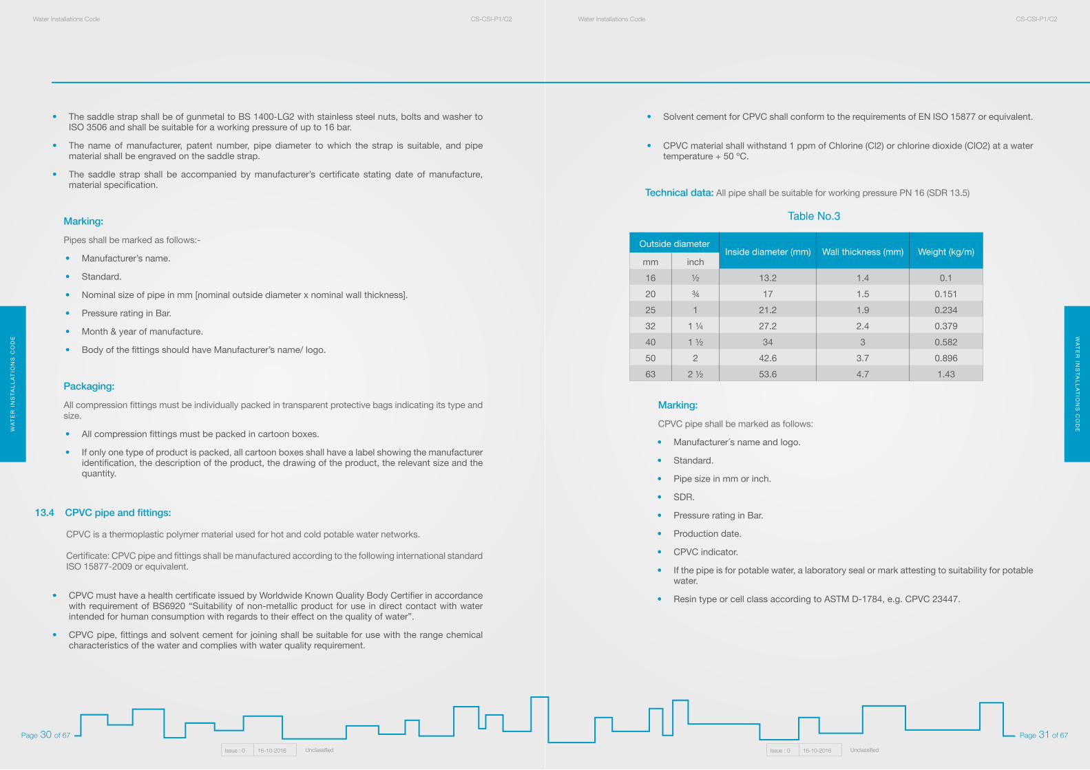
Technical data: All pipe shall be suitable for working pressure PN 16 (SDR 13.5)
Marking:
CPVC pipe shall be marked as follows:
• Manufacturer´s name and logo.
• Standard.
• Pipe size in mm or inch.
• SDR.
• Pressure rating in Bar.
• Production date.
• CPVC indicator.
• If the pipe is for potable water, a laboratory seal or mark attesting to suitability for potable water.
• Resin type or cell class according to ASTM D-1784, e.g. CPVC 23447.
Outside diameter Inside diameter (mm) Wall thickness (mm) Weight (kg/m)
mm inch
16 ½ 13.2 1.4 0.1
20 ¾ 17 1.5 0.151
25 1 21.2 1.9 0.234
32 1 ¼ 27.2 2.4 0.379
40 1 ½ 34 3 0.582
50 2 42.6 3.7 0.896
63 2 ½ 53.6 4.7 1.43
Table No.3
• The saddle strap shall be of gunmetal to BS 1400-LG2 with stainless steel nuts, bolts and washer to ISO 3506 and shall be suitable for a working pressure of up to 16 bar.
• The name of manufacturer, patent number, pipe diameter to which the strap is suitable, and pipe material shall be engraved on the saddle strap.
• The saddle strap shall be accompanied by manufacturer’s certificate stating date of manufacture, material specification.
Marking:
Pipes shall be marked as follows:-
• Manufacturer’s name.
• Standard.
• Nominal size of pipe in mm [nominal outside diameter x nominal wall thickness].
• Pressure rating in Bar.
• Month & year of manufacture.
• Body of the fittings should have Manufacturer’s name/ logo.
Packaging:
All compression fittings must be individually packed in transparent protective bags indicating its type and size.
• All compression fittings must be packed in cartoon boxes.
• If only one type of product is packed, all cartoon boxes shall have a label showing the manufacturer identification, the description of the product, the drawing of the product, the relevant size and the quantity.
13.4 CPVC pipe and fittings:
CPVC is a thermoplastic polymer material used for hot and cold potable water networks.
Certificate: CPVC pipe and fittings shall be manufactured according to the following international standard ISO 15877-2009 or equivalent.
• CPVC must have a health certificate issued by Worldwide Known Quality Body Certifier in accordance with requirement of BS6920 “Suitability of non-metallic product for use in direct contact with water intended for human consumption with regards to their effect on the quality of water”.
• CPVC pipe, fittings and solvent cement for joining shall be suitable for use with the range chemical characteristics of the water and complies with water quality requirement.
WA
TE
R I
NS
TA
LL
AT
ION
S C
OD
EW
AT
ER
INS
TA
LL
AT
ION
S C
OD
EWater Installations Code CS-CSI-P1/C2Water Installations Code CS-CSI-P1/C2
Issue : 0 16-10-2016 UnclassifiedIssue : 0 16-10-2016 Unclassified
Page 33 of 67Page 32 of 67
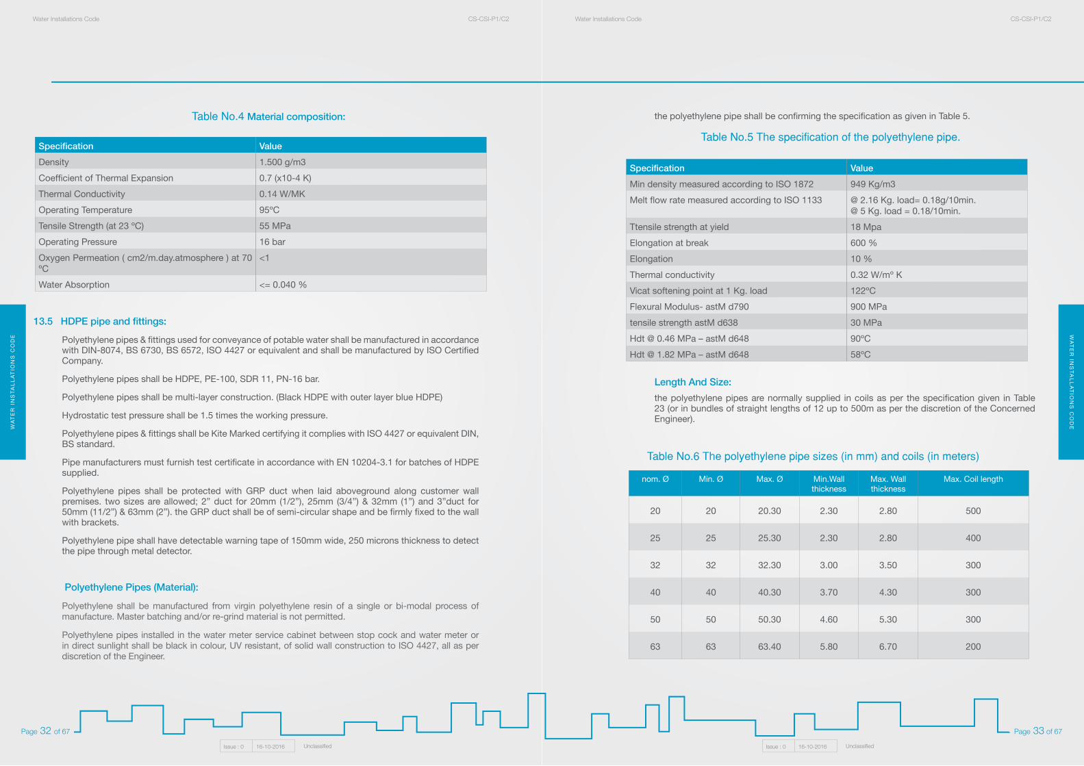
the polyethylene pipe shall be confirming the specification as given in Table 5.
Table No.5 The specification of the polyethylene pipe.
Length And Size:the polyethylene pipes are normally supplied in coils as per the specification given in Table 23 (or in bundles of straight lengths of 12 up to 500m as per the discretion of the Concerned Engineer).
Specification ValueMin density measured according to ISO 1872 949 Kg/m3
Melt flow rate measured according to ISO 1133 @ 2.16 Kg. load= 0.18g/10min.@ 5 Kg. load = 0.18/10min.
Ttensile strength at yield 18 Mpa
Elongation at break 600 %
Elongation 10 %
Thermal conductivity 0.32 W/mº K
Vicat softening point at 1 Kg. load 122ºC
Flexural Modulus- astM d790 900 MPa
tensile strength astM d638 30 MPa
Hdt @ 0.46 MPa – astM d648 90ºC
Hdt @ 1.82 MPa – astM d648 58ºC
nom. Ø Min. Ø Max. Ø Min.Wall thickness
Max. Wall thickness
Max. Coil length
20 20 20.30 2.30 2.80 500
25 25 25.30 2.30 2.80 400
32 32 32.30 3.00 3.50 300
40 40 40.30 3.70 4.30 300
50 50 50.30 4.60 5.30 300
63 63 63.40 5.80 6.70 200
Table No.6 The polyethylene pipe sizes (in mm) and coils (in meters)
13.5 HDPE pipe and fittings:
Polyethylene pipes & fittings used for conveyance of potable water shall be manufactured in accordance with DIN-8074, BS 6730, BS 6572, ISO 4427 or equivalent and shall be manufactured by ISO Certified Company.
Polyethylene pipes shall be HDPE, PE-100, SDR 11, PN-16 bar.
Polyethylene pipes shall be multi-layer construction. (Black HDPE with outer layer blue HDPE)
Hydrostatic test pressure shall be 1.5 times the working pressure.
Polyethylene pipes & fittings shall be Kite Marked certifying it complies with ISO 4427 or equivalent DIN, BS standard.
Pipe manufacturers must furnish test certificate in accordance with EN 10204-3.1 for batches of HDPE supplied.
Polyethylene pipes shall be protected with GRP duct when laid aboveground along customer wall premises. two sizes are allowed; 2” duct for 20mm (1/2”), 25mm (3/4”) & 32mm (1”) and 3”duct for 50mm (11/2”) & 63mm (2”). the GRP duct shall be of semi-circular shape and be firmly fixed to the wall with brackets.
Polyethylene pipe shall have detectable warning tape of 150mm wide, 250 microns thickness to detect the pipe through metal detector.
Polyethylene Pipes (Material):
Polyethylene shall be manufactured from virgin polyethylene resin of a single or bi-modal process of manufacture. Master batching and/or re-grind material is not permitted.
Polyethylene pipes installed in the water meter service cabinet between stop cock and water meter or in direct sunlight shall be black in colour, UV resistant, of solid wall construction to ISO 4427, all as per discretion of the Engineer.
Specification ValueDensity 1.500 g/m3
Coefficient of Thermal Expansion 0.7 (x10-4 K)
Thermal Conductivity 0.14 W/MK
Operating Temperature 95ºC
Tensile Strength (at 23 ºC) 55 MPa
Operating Pressure 16 bar
Oxygen Permeation ( cm2/m.day.atmosphere ) at 70 ºC
<1
Water Absorption <= 0.040 %
Table No.4 Material composition:
WA
TE
R I
NS
TA
LL
AT
ION
S C
OD
EW
AT
ER
INS
TA
LL
AT
ION
S C
OD
EWater Installations Code CS-CSI-P1/C2Water Installations Code CS-CSI-P1/C2
Issue : 0 16-10-2016 UnclassifiedIssue : 0 16-10-2016 Unclassified
Page 35 of 67Page 34 of 67
Ferrule:
Ferrule shall be of gunmetal BS1400-LG2 body with gunmetal compression coupling outlet suitable to fit directly with HDPE service pipe of all size from 20mm to 63mm, for underground application. Gunmetal with PE compression coupling outlet is unacceptable.
Ferrules shall be the screw down valve type allowing for the shut off of the flow by means of “Ω” square head spindle extending from the top cap for opening and closing. The valve shall close clockwise.
The ferrule stern, banjo, spindle, inner plug and top cap shall be of gunmetal to BS1400-LG2. the washers shall be of EPDM and shall provide the sealing between the outer body and the ferrule stem. A polyethylene top plug shall prohibit the ingression of dirt.
The ferrule shall be designed as a main stem with a 360º swivel outlet at 90º with control of water flow via the threaded inner plug. the inlet shall be male taper thread to BS 21.
The ferrule shall be suitable for drinking water at a temperature of up to 50ºC and capable to sustain a working pressure of up to 16 bar without leakage.
The ferrule shall permit the installation of service connection using under pressure tapping through flat boss saddle straps.
Joints:
Fittings shall be of the slide and tighten type using a dynamic sealing method and positive grip.
Marking:
Pipes shall be marked as follows:
• Manufacturer’s name.
• Standard.
• Nominal size of pipe in mm [ nominal outside diameter x nominal wall thickness].
• SDR.
• Pressure rating in Bar.
• Month & year of manufacture.
• Body of the fittings should have Manufacturer’s name / logo.
Packaging:
All compression fittings must be individually packed in transparent protective bags indicating its type and size.
all compression fittings must be packed in cartoon boxes.
If only one type of product is packed, all cartoon boxes shall have a label showing the manufacturer identification, the description of the product, the drawing of the product, the relevant size and the quantity.
the ovality of the pipe in coils as manufactured shall not exceed the value of 0.06 of the nominal size of the pipe.
the ovality of the pipe in coils after relaxation and straight pipe shall not exceed the value of “1
+ (0.008 of the nominal size of the pipe).
Fittings:
all fitting for polyethylene pipes (HDPE) shall be compression type (Gunmetal) and all details are given in Section 15.
Stop Valve:
For underground installation - stop valve shall be made of gunmetal BS 5433 crutch head with gunmetal ended compression couplings to fit HDPE pipe both sides for all size range from 20mm up to 63mm.
For aboveground installation inside/outside service cabinet before water meter stop valve shall be of brass tamper proof lockable type as per discretion of the concerned engineer. Suitable size of gunmetal compression couplings at both sides shall be used in connecting HDPE pipe of all size range from 20mm up to 63mm.
Flanged Fittings:
Flange adaptor to join HDPE pipe to flanged equipments (63mm od HDPE pipe to 2” Ø flange to BS 4504 / ISO 7005, BS EN 1092-2 with PN 16 rating). Material: black coated steel or SG Iron to BS EN 1563:1997 Grade EN-GJS-450-10, Gasket: EDPM compound Grade ‘E’.
Saddle Straps:
Saddle straps for service connections shall be flat boss type suitable for tapping from ½” up to 2” diameter ferrule. The strap shall be suitable for making service connections under pressure or dry using approved tapping machine into DI, AC steel or PVC pipes. The saddle shall be of two parts fitted with EPDM sealing gasket in a groove on the underside of the flat boss.
The flat boss shall be cast with a hole or marking through the boss to facilitate the drilling and tapping process. the straps shall be supplied un-drilled.
The saddle strap shall be of gunmetal to BS 1400-lG2 with stainless steel nuts, bolts and washer to ISO 3506 and shall be suitable for a working pressure of up to 16 bar.
The name of manufacturer, patent number, pipe diameter to which the strap is suitable, and pipe material shall be engraved on the saddle strap.
The saddle strap shall be accompanied by manufacturer’s certificate stating date of manufacture, material specification.
WA
TE
R I
NS
TA
LL
AT
ION
S C
OD
EW
AT
ER
INS
TA
LL
AT
ION
S C
OD
EWater Installations Code CS-CSI-P1/C2Water Installations Code CS-CSI-P1/C2
Issue : 0 16-10-2016 UnclassifiedIssue : 0 16-10-2016 Unclassified
Page 37 of 67Page 36 of 67
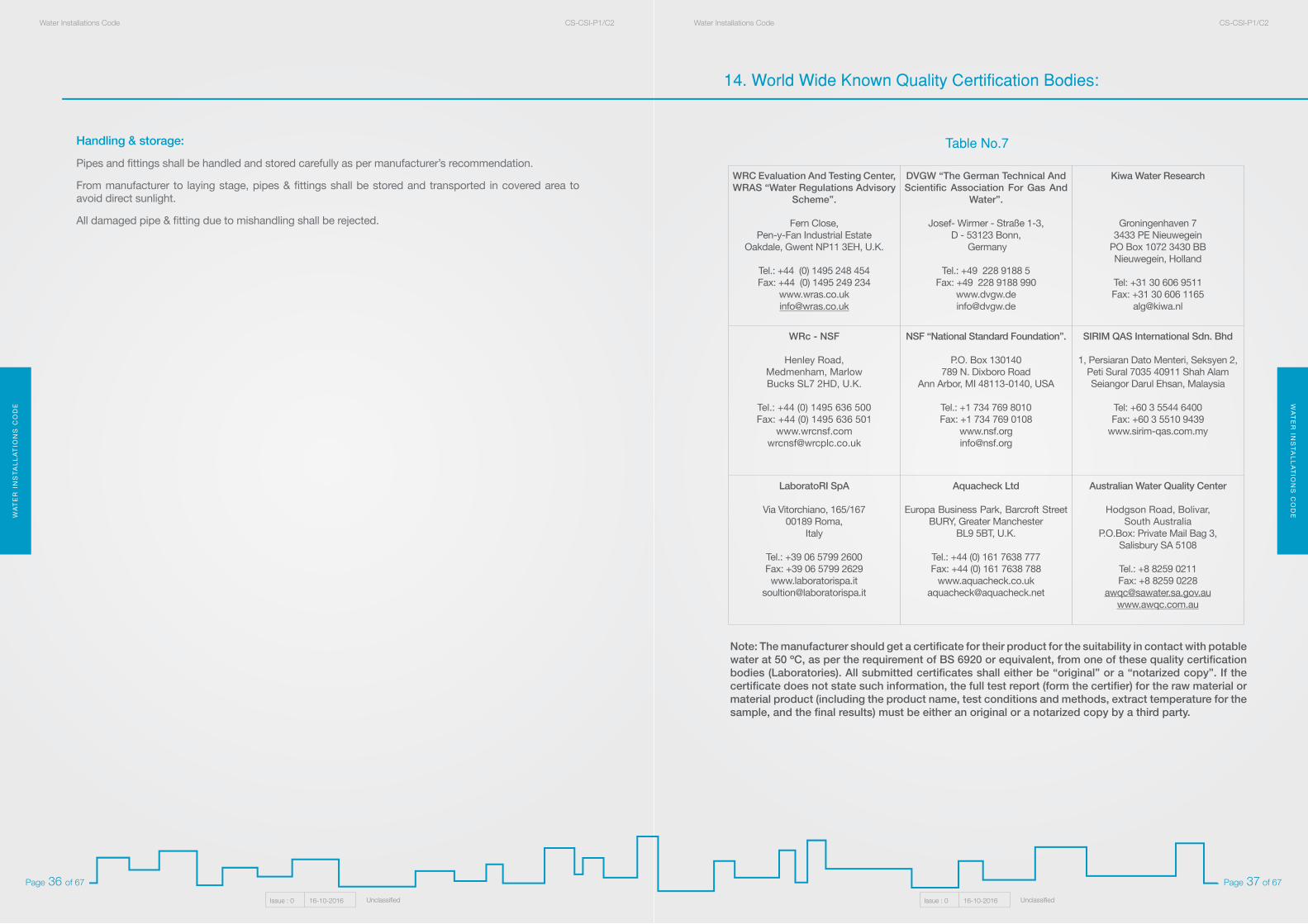
Note: The manufacturer should get a certificate for their product for the suitability in contact with potable water at 50 ºC, as per the requirement of BS 6920 or equivalent, from one of these quality certification bodies (Laboratories). All submitted certificates shall either be “original” or a “notarized copy”. If the certificate does not state such information, the full test report (form the certifier) for the raw material or material product (including the product name, test conditions and methods, extract temperature for the sample, and the final results) must be either an original or a notarized copy by a third party.
WRC Evaluation And Testing Center,WRAS “Water Regulations Advisory
Scheme”.
Fern Close, Pen-y-Fan Industrial Estate
Oakdale, Gwent NP11 3EH, U.K.
Tel.: +44 (0) 1495 248 454Fax: +44 (0) 1495 249 234
DVGW “The German Technical AndScientific Association For Gas And
Water”.
Josef- Wirmer - Straße 1-3,D - 53123 Bonn,
Germany
Tel.: +49 228 9188 5Fax: +49 228 9188 990
www.dvgw.de [email protected]
Kiwa Water Research
Groningenhaven 7
3433 PE NieuwegeinPO Box 1072 3430 BB Nieuwegein, Holland
Tel: +31 30 606 9511Fax: +31 30 606 1165
WRc - NSF
Henley Road,Medmenham, MarlowBucks SL7 2HD, U.K.
Tel.: +44 (0) 1495 636 500Fax: +44 (0) 1495 636 501
NSF “National Standard Foundation”.
P.O. Box 130140789 N. Dixboro Road
Ann Arbor, MI 48113-0140, USA
Tel.: +1 734 769 8010Fax: +1 734 769 0108
www.nsf.org [email protected]
SIRIM QAS International Sdn. Bhd
1, Persiaran Dato Menteri, Seksyen 2, Peti Sural 7035 40911 Shah AlamSeiangor Darul Ehsan, Malaysia
Tel: +60 3 5544 6400Fax: +60 3 5510 9439
www.sirim-qas.com.my
LaboratoRI SpA
Via Vitorchiano, 165/16700189 Roma,
Italy
Tel.: +39 06 5799 2600Fax: +39 06 5799 2629www.laboratorispa.it
Aquacheck Ltd
Europa Business Park, Barcroft Street BURY, Greater Manchester
BL9 5BT, U.K.
Tel.: +44 (0) 161 7638 777Fax: +44 (0) 161 7638 788
Australian Water Quality Center
Hodgson Road, Bolivar, South Australia
P.O.Box: Private Mail Bag 3,Salisbury SA 5108
Tel.: +8 8259 0211Fax: +8 8259 0228
14. World Wide Known Quality Certification Bodies:
Table No.7Handling & storage:
Pipes and fittings shall be handled and stored carefully as per manufacturer’s recommendation.
From manufacturer to laying stage, pipes & fittings shall be stored and transported in covered area to avoid direct sunlight.
All damaged pipe & fitting due to mishandling shall be rejected.
WA
TE
R I
NS
TA
LL
AT
ION
S C
OD
EW
AT
ER
INS
TA
LL
AT
ION
S C
OD
EWater Installations Code CS-CSI-P1/C2Water Installations Code CS-CSI-P1/C2
Issue : 0 16-10-2016 UnclassifiedIssue : 0 16-10-2016 Unclassified
Page 39 of 67Page 38 of 67
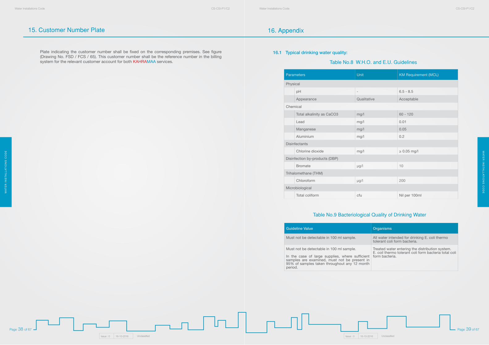
16.1 Typical drinking water quality:
Table No.8 W.H.O. and E.U. Guidelines
Table No.9 Bacteriological Quality of Drinking Water
Parameters Unit KM Requirement (MCL)
Physical
pH - 6.5 - 8.5
Appearance Qualitative Acceptable
Chemical
Total alkalinity as CaCO3 mg/l 60 - 120
Lead mg/l 0.01
Manganese mg/l 0.05
Aluminium mg/l 0.2
Disinfectants
Chlorine dioxide mg/l ≥ 0.05 mg/l
Disinfection by-products (DBP)
Bromate µg/l 10
Trihalomethane (THM)
Chloroform µg/l 200
Microbiological
Total coliform cfu Nil per 100ml
Guideline Value Organisms
Must not be detectable in 100 ml sample. All water intended for drinking E. coli thermo tolerant coli form bacteria.
Must not be detectable in 100 ml sample.
In the case of large supplies, where sufficient samples are examined, must not be present in 95% of samples taken throughout any 12 month period.
Treated water entering the distribution system.E. coil thermo tolerant coli form bacteria total coli form bacteria.
16. Appendix
Plate indicating the customer number shall be fixed on the corresponding premises. See figure (Drawing No. FSD / FCS / 65). This customer number shall be the reference number in the billing system for the relevant customer account for both KAHRAMAA services.
15. Customer Number Plate
WA
TE
R I
NS
TA
LL
AT
ION
S C
OD
EW
AT
ER
INS
TA
LL
AT
ION
S C
OD
EWater Installations Code CS-CSI-P1/C2Water Installations Code CS-CSI-P1/C2
Issue : 0 16-10-2016 UnclassifiedIssue : 0 16-10-2016 Unclassified
Page 41 of 67Page 40 of 67
17. Water Conservation Regulations
Relevant forms for the water services application are available in the appendix:
• Residential Complex Internal Water Network Hydro Test.
• Temporary Supply, Diversion and Increase Meter Diameter.
• Building Permit Form.
• Building Permit Form for Bulk Customer.
• Water Inspection Check List.
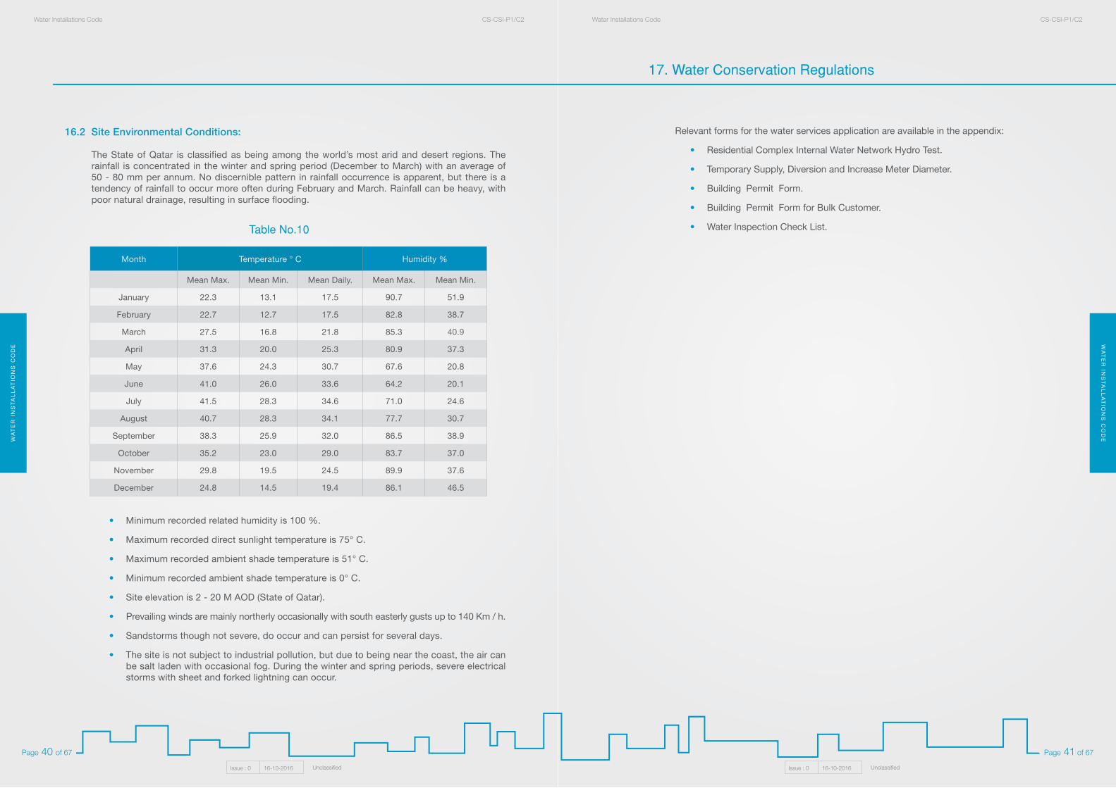
Humidity %Temperature ° CMonth
Mean Min.Mean Max.Mean Daily.Mean Min.Mean Max.
51.990.717.513.122.3January
38.782.817.512.722.7February
40.985.321.816.827.5March
37.380.925.320.031.3April
20.867.630.724.337.6May
20.164.233.626.041.0June
24.671.034.628.341.5July
30.777.734.128.340.7August
38.986.532.025.938.3September
37.083.729.023.035.2October
37.689.924.519.529.8November
46.586.119.414.524.8December
16.2 Site Environmental Conditions:
The State of Qatar is classified as being among the world’s most arid and desert regions. The rainfall is concentrated in the winter and spring period (December to March) with an average of 50 - 80 mm per annum. No discernible pattern in rainfall occurrence is apparent, but there is a tendency of rainfall to occur more often during February and March. Rainfall can be heavy, with poor natural drainage, resulting in surface flooding.
• Minimum recorded related humidity is 100 %.
• Maximum recorded direct sunlight temperature is 75° C.
• Maximum recorded ambient shade temperature is 51° C.
• Minimum recorded ambient shade temperature is 0° C.
• Site elevation is 2 - 20 M AOD (State of Qatar).
• Prevailing winds are mainly northerly occasionally with south easterly gusts up to 140 Km / h.
• Sandstorms though not severe, do occur and can persist for several days.
• The site is not subject to industrial pollution, but due to being near the coast, the air can be salt laden with occasional fog. During the winter and spring periods, severe electrical storms with sheet and forked lightning can occur.
Table No.10
WA
TE
R I
NS
TA
LL
AT
ION
S C
OD
EW
AT
ER
INS
TA
LL
AT
ION
S C
OD
EWater Installations Code CS-CSI-P1/C2Water Installations Code CS-CSI-P1/C2
Issue : 0 16-10-2016 UnclassifiedIssue : 0 16-10-2016 Unclassified
Page 43 of 67Page 42 of 67
Lavatories & Sinks shall conform to the applicable requirements of Section 416 and Section 418, International Plumbing Code 2006. The conformity shall be verified by laboratories accredited by International Institutions.
4. Showers:The flow rate of shower head or hand held showers shall not exceed 9.5 L/min (or 2.5 gpm) at an operating pressure of 5.5 bar (80 psi). Showers shall conform to the applicable requirements of Section 417, International Plumbing Code 2006. The conformity shall be verified by laboratories accredited by International Institutions.
01.1 B) Irrigation:
1. Type of Irrigation System
Consumers with irrigation water requirement exceeding 1 m3 per day and/or the irrigated area is greater than or equal to 100 m2 shall comply with the following requirements:
• Flood irrigation is not allowed. Projects shall use irrigation systems such as drip irrigation or sprinkler systems or bubbles along with timers or weather based controllers.
• Separate irrigation tanks to be used.
2. Restricted potable Water Usage for Irrigation
• Consumers shall not use potable water if the irrigation water requirements exceed 85 m3 per day and/or the irrigated area is greater than or equal to 7000 m2.
• Consumers shall use Treated Water and/or Treated Grey water and/or condensate recovery or any other non-potable water resources to meet the requirements. Treated water used for irrigation should meet applicable health and safety standards of the state of Qatar prescribed by competent authority.
3. Metering of water use for irrigation Consumers with irrigation water demand of more than 25 m3 per day • Shall submit irrigation plan detailing species type and irrigation system.
• Provide a separate meter for Irrigation water consumption.
• Track the consumption on monthly basis.
• Submit water consumption data to KAHRAMAA when requested.
01.1 C) Water Conservation Plumbing GuidelinesIn addition to plumbing practices stipulated in other sections of this regulation the following practices are recommended.
• Water tanks exposed to direct sun shall be insulated or shaded to reduce the heat gain.
• Water supply pipes exposed to direct sun shall be insulated.
• Minimize the length of pipes from water heaters to tap/faucets and showers in order to reduce the heat loss from the pipes.
01.1 D) Non-Conventional Energy for Plumbing Applications: Non-conventional energy sources for plumbing applications like solar water heater are encouraged. The best practices stipulated in this section are demonstrated in the drawing CN-CNC-WA 01.
1.0 Water Conservation:Considerable amount of energy is consumed to deliver and treat the water we are using every day. By reducing the water use by efficient means will reduce the water consumption and the energy required in distribution network and treatment plants. In designing plumbing systems, utilize new techniques and options that can lead to maximum water efficiency and water savings. The plumbing system for new and addition to existing buildings by all consultants, customers and developers shall comply with the requirements of section 1.1 A & B of this chapter.
01.1 A) Maximum allowable flow rates for plumbing fixtures:
1. Water Closets:
The flush rates of single flush Water Closets either flush tank, flushometer tank or flushometer valve operated shall not exceed 4.9 L/flush (or 1.28 gpf). In case of dual flush toilets the flush rate shall not exceed 6 L/flush (or 1.6 gpf) for full flush and 4.2 L/flush (or 1.1 gpf) for reduced flush.
Control valve shall be installed on the inlet line to the flush tank/flush valve in order to shutoff them in case of leakage.
Water Closets shall conform to the applicable requirements of Section 420, International Plumbing Code 2006. The conformity shall be verified by laboratories accredited by International Institutions.
2. Urinals:
The flush rates for all type of Urinals shall not exceed 1.9 L/flush (or 0.5 gpf). The urinal system shall be flushed only after usage.
Urinals shall conform to the applicable requirements of Section 419, International Plumbing Code 2006. The conformity shall be verified by laboratories accredited by International Institutions.
3. Faucets:
The flow rates of faucets shall not exceed the flow rates stipulated in Table 1.1
Table No.11 Maximum allowable flow rate for faucets# Plumbing Fixtures/Fixture fittings Maximum allowable flow rate
1Lavatory Faucet – Residential Occupancy (Residential, Hotel-Guest rooms only, Hospital-patient rooms only)
5.7 L/min (or 1.5 gpm) at an operating pressure of 4 bar (60 PSI)
2Lavatory Faucet – Nonresidential occupancy
3.8 l/min (or 1 gpm) at an operating pressure of 4 bar (60 PSI)
3 Kitchen Sinks 8.3 L/min (or 2.2 gpm) at an operating pressure of 4 bar (60 PSI)
Exclusion: Bath tub taps or any other taps where a pre-quantified amount of water need to be filled are excluded from requirements of Table 1.1
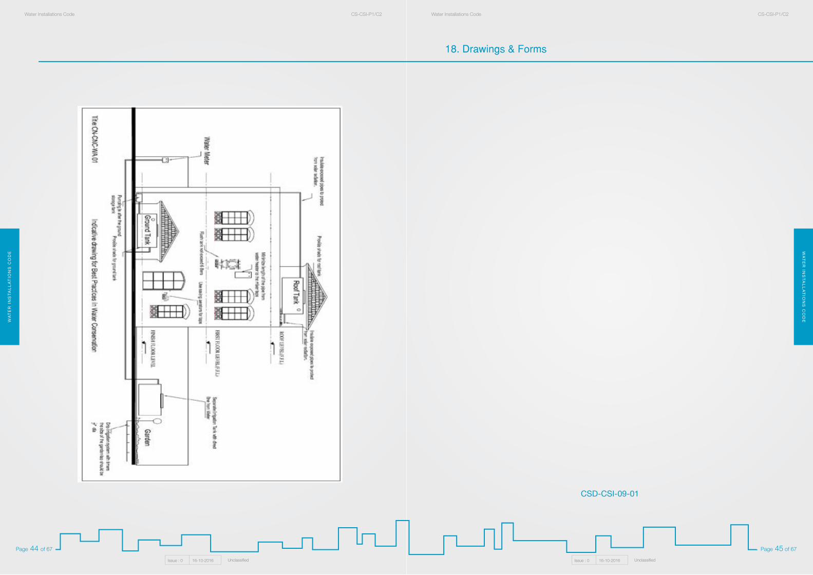
WA
TE
R I
NS
TA
LL
AT
ION
S C
OD
EW
AT
ER
INS
TA
LL
AT
ION
S C
OD
EWater Installations Code CS-CSI-P1/C2Water Installations Code CS-CSI-P1/C2
Issue : 0 16-10-2016 UnclassifiedIssue : 0 16-10-2016 Unclassified
Page 45 of 67Page 44 of 67
18. Drawings & Forms
CSD-CSI-09-01
WA
TE
R I
NS
TA
LL
AT
ION
S C
OD
EW
AT
ER
INS
TA
LL
AT
ION
S C
OD
EWater Installations Code CS-CSI-P1/C2Water Installations Code CS-CSI-P1/C2
Issue : 0 16-10-2016 UnclassifiedIssue : 0 16-10-2016 Unclassified
Page 47 of 67Page 46 of 67
WA
TE
R I
NS
TA
LL
AT
ION
S C
OD
EW
AT
ER
INS
TA
LL
AT
ION
S C
OD
EWater Installations Code CS-CSI-P1/C2Water Installations Code CS-CSI-P1/C2
Issue : 0 16-10-2016 UnclassifiedIssue : 0 16-10-2016 Unclassified
Page 49 of 67Page 48 of 67
CSD-CSI-09-05
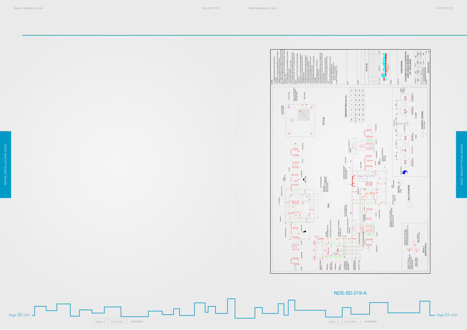
WA
TE
R I
NS
TA
LL
AT
ION
S C
OD
EW
AT
ER
INS
TA
LL
AT
ION
S C
OD
EWater Installations Code CS-CSI-P1/C2Water Installations Code CS-CSI-P1/C2
Issue : 0 16-10-2016 UnclassifiedIssue : 0 16-10-2016 Unclassified
Page 51 of 67Page 50 of 67
Draw
ing N
o.
Cons
ultan
t
Draw
ing T
itle
Rev.
DRAW
NDE
SIGN
EDCH
ECKE
DAP
PROV
ED
REV.
DESC
RIPT
ION
DATE
APPR
'D
ACTU
AL S
IZE
A1DA
TE
CONT
RACT
No:
STAT
US
G.I.S
. SEC
TION
WAT
ER N
ETW
ORK
AFFA
IRS
Proje
ct No
.
Proje
ct
B
A
SUMP
500X
500X
300M
M
SEE
NOTE
3 375
600
375
500
GRP
LADD
ER
(NOT
TO
SCAL
E)
DN
DN
CONC
RETE
SUP
PORT
COLL
AR
IN R
OAD
FLOW
MET
ER
DISM
ANTL
ING
JOIN
T
PLAN
NDS-
SD-2
30FO
R DE
TAILS
PLE
ASE
REFE
R TO
WAT
ER P
ROOF
ING
TO G
RP C
ABIN
ET
TOP
PLAN
LIFTI
NG H
OOCK
S
CONC
RETE
STR
UCTU
RE IS
SHO
WN
DIAG
RAMM
ATIC
ALLY
FOR
REQ
UIRE
MENT
SEE
STRU
CTUR
AL N
OTES
SUMP
500X
500X
300M
M
FOR
SLAB
DIM
ENSI
ONS
SEE
STRU
CTUR
AL N
OTES
SVSV
ROCK
ER P
IPE
ROCK
ER P
IPE
A -
NDS
NDS
NDS
NDS
1:20
1:40
24-S
EP-2
017
NDS
NDS
NDS-
SD-2
19-A
CUST
OMER
'S B
ULK
FLOW
MET
ER F
ORUN
DER
GROU
ND R
ESER
VOIR
(100
- 30
0mm
MAIN
S)
NOTE
S:
ROCK
ER P
IPE
ROCK
ER P
IPE
COLL
ARRO
CKER
PIP
E
ROCK
ER P
IPE
ROCK
ER P
IPE
ROCK
ER P
IPE
GUNM
ETAL
FIT
TING
S TO
CONN
ECT
G.V
WIT
H PR
ESSU
RETR
ANSD
UCER
WIT
H QU
ICK
RELE
ASE
COUP
LING
PRES
SURE
TRA
NSDU
CER
CABL
ESU
PPOR
TED
ON G
.I TRU
CKIN
G OR
GRP/
PLAS
TIC
RECT
ANGU
LAR
DUCT
(TYP
.)
Ø50m
m GU
NMET
ALIN
SERT
ION
NIPP
LEØ5
0mm
GUNM
ETAL
GATE
VAL
VE (1
6 BAR
)
DETA
IL-A
INS
ERTI
ON N
IPPL
E
GRP
LADD
ERFO
R DE
PTH
OF C
HAMB
ER M
ORE
THAN
2.50
0m U
SE LA
DDER
WIT
HPR
OTEC
TION
CAG
E.
FOR
DETA
ILS S
EE D
RAW
ING
NDS-
SD-2
01DE
TAIL
NO.2
SEE
DETA
IL- A
SECT
ION
BULK
FLO
W M
ETER
-A
SCHE
MATI
C D
IAGR
AM
750x
750m
m CL
EAR
OPEN
ING
WIT
H DO
UBLE
TRI
ANGL
ECO
VER
AND
FRAM
E
750x
750m
m CL
EAR
OPEN
ING
WIT
H DO
UBLE
TRI
ANGL
ECO
VER
AND
FRAM
E
PUDD
LEFL
ANGE
(TYP
)
PUDD
LEFL
ANGE
(TYP
)
SEE
NOTE
15
FPL
FPL
F
EE 20
0MM
x DIA
WAT
ER P
ROOF
ING
COLL
AR
EE
C
C
G
600
1.5 x
D (T
YP)
COLL
AR
COLL
ARCO
LLAR
600
1.5 x
D60
01.5
x D
1.5 x
D
COLL
AR
COLL
AR
1.5 x
D
1.5 x
D1.5
x D
200X
150 C
HAMB
ERIN
DICA
TION
PLA
TE
DIA
AB
CE
FG
100 -
150
1500
1700
250
250
500
200
200
1600
1800
250
250
500
200
300
1700
1900
250
300
500
200
DIME
NSIO
N TA
BLE
(mm)
min.
1.ALL
DIM
ENSI
ONS
ARE
IN M
ILLIM
ETER
S UN
LESS
STA
TED
OTH
ERW
ISE.
2.ALL
EXT
ERNA
L CON
CRET
E CH
AMBE
R SU
RFAC
E TO
HAV
E TA
NKIN
G M
EMBR
ANE
IN A
CCOR
DANC
E W
ITH
SPEC
IFIC
ATIO
NS.
3.ALL
INTE
RNAL
SUR
FACE
S TO
BE
PAIN
TED
ON A
WAT
ER P
ROOF
NON
TOXI
C BA
SED
ON C
EMEN
TITI
OUS
MATE
RIAL
WHI
CH A
LSO
HAS
THE
PROP
ERTY
OF
SEAL
ING
VOID
S IN
PRO
TECT
ING
CONC
RET
FROM
ANY
CORR
OSIV
E AC
T ON
.4.P
OLYT
HENE
SHE
ETIN
G TO
BE
PLAC
ED B
ETW
EEN
ALL V
ALVE
S AN
D C
ONCR
ETE
SUPP
ORT
PLIN
THS.
5.SLO
PE F
LOOR
OF
CHAM
BER
AT 1:
100 T
O SU
MP6.A
LL G
RP LA
DDER
TO
BE IN
ACC
ORDA
NCE
WIT
H SP
ECIF
ICAT
IONS
.GR
P LA
DDER
WIT
H CA
GE IF
DEP
TH O
F CH
AMBE
R IS
MOR
E TH
AN25
00mm
.7.P
IPE
AND
VALV
E IN
FO T
O BE
CLE
ARLY
MAR
KED
ON T
HE S
LAB
AS
SPEC
IFIE
D.8.D
IMEN
SION
S OF
ALL
REI
NFOR
CED
CONC
RETE
CHA
MBER
S TO
BE
DESI
GNED
BY
THE
CONT
RACT
OR A
ND S
UBMI
TTED
FOR
ENG
INEE
R'S
APPR
OVAL
.9.T
HE C
ONTR
ACTO
R TO
CON
FIRM
, WHE
RE A
PPLIC
ABLE
THE
PIP
E SC
HEDU
LE O
F FI
TTIN
GS F
OR C
HAMB
ERS
PRIO
R TO
PLA
CEME
NT O
F OR
DERS
AND
CON
STRU
CTIO
N.10
.ALL
PIP
ING
INSI
DE C
HAMB
ERS
TO B
E DU
CTILE
IRON
IN A
CCOR
DANC
E W
ITH
SPEC
IFIC
ATIO
NS.
11.A
LL F
LANG
ES A
RE T
O BS
4504
TAB
LE 16
UNL
ESS
NOTE
D O
THER
WIS
E.12
.PIP
E W
ORK
DIME
NSIO
NS A
RE T
O CE
NTER
LINE
S P
IPE
ENDS
OR
FLAN
GE F
ACE.
13.A
LL F
LANG
ES A
ND C
OUPL
INGS
OUT
SIDE
OF
CHAM
BERS
TO
BE P
ROTE
CTED
BY
HEAT
SHR
INKA
BLE
SLEE
VING
IN A
CCOR
DANC
E W
ITH
SPEC
IFIC
ATIO
N.14
.THI
S DR
AWIN
G RE
PLAC
ES K
AHRA
MAA
DRAW
ING
NO.
NDS
-SD-
101A
BV
400-
700 R
EV &
NDS-
SD-1
01B
BV 80
0-14
00 R
EV.
15. R
EFER
TO
DRAW
ING
NUMB
ER N
DS-S
D-20
1 (Re
v:A) F
OR
MI
SCEL
LANE
OUS
CHAM
BER
DETA
ILS F
OR ,
15a.
DETA
IL - 5
FOR
CAR
RIAG
EWAY
etc..
15b.
DETA
IL - 6
FOR
VER
GE et
c..16
. LEN
GTH
OF R
OCKE
R PI
PE =
1.5 x
D
300500
100
1200
1000
1000
300
100
100
100
100
SV
FM
BOUN
DARY
WAL
L
FCV
SV
SERV
ICE
PIPE
ROAD
CUST
OMER
SV
KM W
ATER
MAI
N
1 mete
r5x
DN3x
DN1 m
eter
3xDN
DWG.
NO:
NDS
-SD-
230
PLEA
SE R
EFER
TO
DWG.
NO:
NDS
-SD-
230
PLEA
SE R
EFER
TO
DWG.
NO:
NDS
-SD-
230
PLEA
SE R
EFER
TO
DWG.
NO:
NDS
-SD-
208
PLEA
SE R
EFER
TO
BULK
FLO
W M
ETER
TO U
NDER
GROU
NDRE
SERV
OIR
A
NDS-SD-219-A
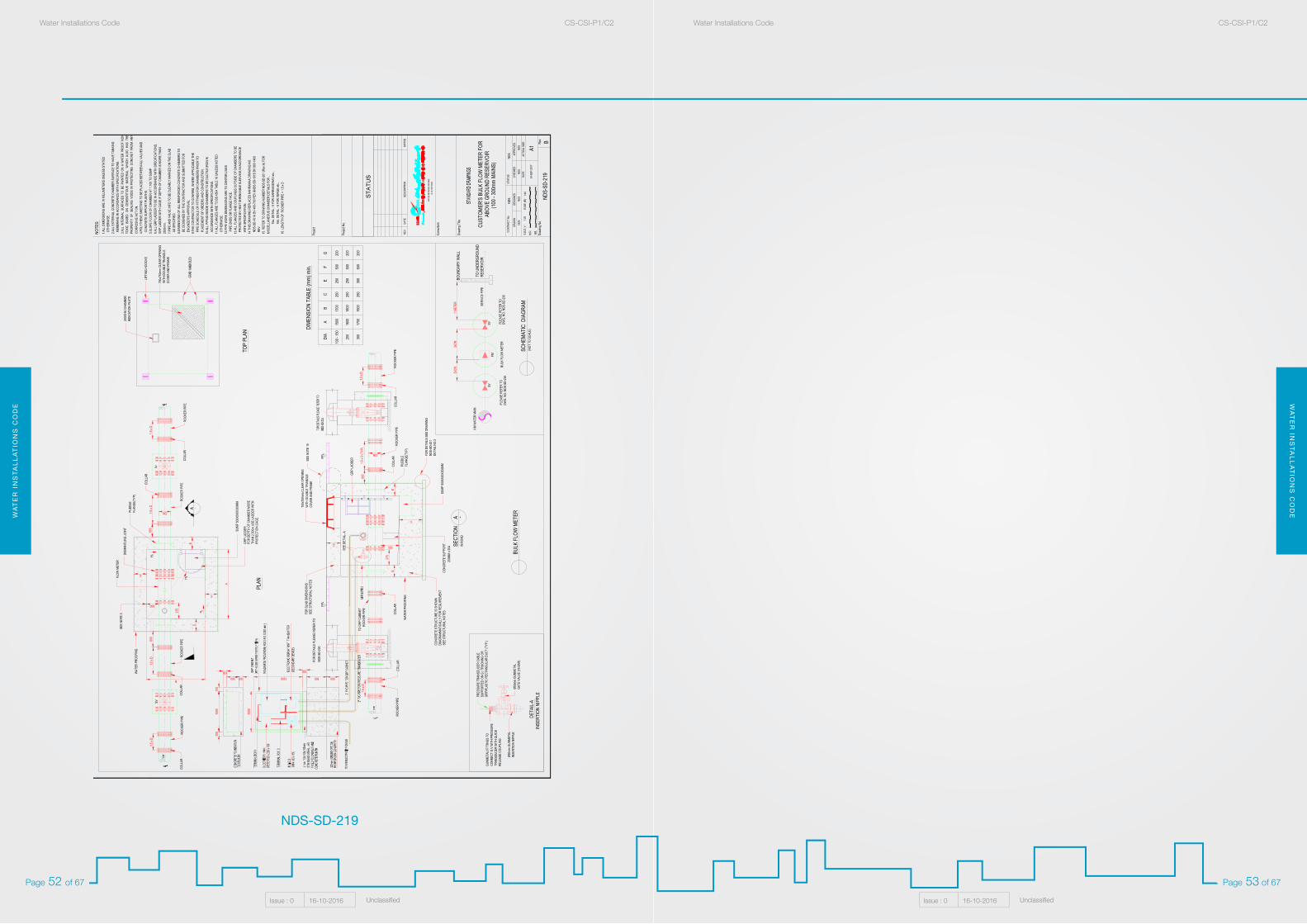
WA
TE
R I
NS
TA
LL
AT
ION
S C
OD
EW
AT
ER
INS
TA
LL
AT
ION
S C
OD
EWater Installations Code CS-CSI-P1/C2Water Installations Code CS-CSI-P1/C2
Issue : 0 16-10-2016 UnclassifiedIssue : 0 16-10-2016 Unclassified
Page 53 of 67Page 52 of 67
NDS-SD-219
Draw
ing N
o.
Cons
ultan
t
Draw
ing T
itle
Rev.
DRAW
NDE
SIGN
EDCH
ECKE
DAP
PROV
ED
REV.
DESC
RIPT
ION
DATE
APPR
'D
ACTU
AL S
IZE
A1DA
TE
CONT
RACT
No:
STAT
US
G.I.S
. SEC
TION
WAT
ER N
ETW
ORK
AFFA
IRS
Proje
ct No
.
Proje
ct
SVFM
BOUN
DARY
WAL
L
SERV
ICE
PIPE
BULK
FLO
W M
ETER
B
A
SUMP
500X
500X
300M
M
SEE
NOTE
3
375
600
375
500
SV
KM W
ATER
MAI
N
GRP
LADD
ER
(NOT
TO
SCAL
E)
DWG.
NO:
NDS
-SD-
230
PLEA
SE R
EFER
TO
DWG.
NO:
NDS
-SD-
230
PLEA
SE R
EFER
TO
DN
DN
1 MET
ER
RESE
RVOI
R
5xDN
3xDN
CONC
RETE
SUP
PORT
COLL
AR
IN R
OAD
FLOW
MET
ER
DISM
ANTL
ING
JOIN
T
PLAN
NDS-
SD-2
30FO
R DE
TAILS
PLE
ASE
REFE
R TO
WAT
ER P
ROOF
ING
TO G
RP C
ABIN
ET
TOP
PLAN
LIFTI
NG H
OOCK
S
CONC
RETE
STR
UCTU
RE IS
SHO
WN
DIAG
RAMM
ATIC
ALLY
FOR
REQ
UIRE
MENT
SEE
STRU
CTUR
AL N
OTES
SUMP
500X
500X
300M
M
FOR
SLAB
DIM
ENSI
ONS
SEE
STRU
CTUR
AL N
OTES
SVSV
TO U
NDER
GROU
ND
ROCK
ER P
IPE
ROCK
ER P
IPE
A -
NDS
NDS
NDS
NDS
1:20
1:40
24-S
EP-2
017
NDS
NDS
NDS-
SD-2
19
CUST
OMER
'S B
ULK
FLOW
MET
ER F
ORAB
OVE
GROU
ND R
ESER
VOIR
(100
- 30
0mm
MAIN
S)
NOTE
S:
ROCK
ER P
IPE
ROCK
ER P
IPE
COLL
ARRO
CKER
PIP
E
ROCK
ER P
IPE
ROCK
ER P
IPE
ROCK
ER P
IPE
GUNM
ETAL
FIT
TING
S TO
CONN
ECT
G.V
WIT
H PR
ESSU
RETR
ANSD
UCER
WIT
H QU
ICK
RELE
ASE
COUP
LING
PRES
SURE
TRA
NSDU
CER
CABL
ESU
PPOR
TED
ON G
.I TRU
CKIN
G OR
GRP/
PLAS
TIC
RECT
ANGU
LAR
DUCT
(TYP
.)
Ø50m
m GU
NMET
ALIN
SERT
ION
NIPP
LEØ5
0mm
GUNM
ETAL
GATE
VAL
VE (1
6 BAR
)
DETA
IL-A
INS
ERTI
ON N
IPPL
E
GRP
LADD
ERFO
R DE
PTH
OF C
HAMB
ER M
ORE
THAN
2.50
0m U
SE LA
DDER
WIT
HPR
OTEC
TION
CAG
E.
FOR
DETA
ILS S
EE D
RAW
ING
NDS-
SD-2
01DE
TAIL
NO.2
SEE
DETA
IL- A
SECT
ION
BULK
FLO
W M
ETER-A
SCHE
MATI
C D
IAGR
AM
750x
750m
m CL
EAR
OPEN
ING
WIT
H DO
UBLE
TRI
ANGL
ECO
VER
AND
FRAM
E
750x
750m
m CL
EAR
OPEN
ING
WIT
H DO
UBLE
TRI
ANGL
ECO
VER
AND
FRAM
E
PUDD
LEFL
ANGE
(TYP
)
PUDD
LEFL
ANGE
(TYP
)
SEE
NOTE
15
FPL
FPL
F
EE
200M
M x D
IA
WAT
ER P
ROOF
ING
COLL
AR
EE
C
C
G
600
1.5 x
D (T
YP)
COLL
AR
COLL
ARCO
LLAR
600
1.5 x
D60
01.5
x D
1.5 x
D
COLL
AR
COLL
AR
1.5 x
D
1.5 x
D1.5
x D
200X
150 C
HAMB
ERIN
DICA
TION
PLA
TE
DIA
AB
CE
FG
100 -
150
1500
1700
250
250
500
200
200
1600
1800
250
250
500
200
300
1700
1900
250
300
500
200
DIME
NSIO
N TA
BLE
(mm)
min.
1.ALL
DIM
ENSI
ONS
ARE
IN M
ILLIM
ETER
S UN
LESS
STA
TED
OTH
ERW
ISE.
2.ALL
EXT
ERNA
L CON
CRET
E CH
AMBE
R SU
RFAC
E TO
HAV
E TA
NKIN
G M
EMBR
ANE
IN A
CCOR
DANC
E W
ITH
SPEC
IFIC
ATIO
NS.
3.ALL
INTE
RNAL
SUR
FACE
S TO
BE
PAIN
TED
ON A
WAT
ER P
ROOF
NON
TOXI
C BA
SED
ON C
EMEN
TITI
OUS
MATE
RIAL
WHI
CH A
LSO
HAS
THE
PROP
ERTY
OF
SEAL
ING
VOI
DS IN
PRO
TECT
ING
CON
CRET
FRO
M A
NYCO
RROS
IVE
ACT
ON.
4.POL
YTHE
NE S
HEET
ING
TO B
E PL
ACED
BET
WEE
N AL
L VAL
VES
AND
CON
CRET
E SU
PPOR
T PL
INTH
S.5.S
LOPE
FLO
OR O
F CH
AMBE
R AT
1:10
0 TO
SUMP
6.ALL
GRP
LADD
ER T
O BE
IN A
CCOR
DANC
E W
ITH
SPEC
IFIC
ATIO
NS.
GRP
LADD
ER W
ITH
CAGE
IF D
EPTH
OF
CHAM
BER
IS M
ORE
THAN
2500
mm.
7.PIP
E AN
D VA
LVE
INFO
TO
BE C
LEAR
LY M
ARKE
D ON
THE
SLA
B A
S SP
ECIF
IED.
8.DIM
ENSI
ONS
OF A
LL R
EINF
ORCE
D CO
NCRE
TE C
HAMB
ERS
TO B
E DE
SIGN
ED B
Y TH
E CO
NTRA
CTOR
AND
SUB
MITT
ED F
OR E
NGIN
EER'
S AP
PROV
AL.
9.THE
CON
TRAC
TOR
TO C
ONFI
RM, W
HERE
APP
LICAB
LE T
HE P
IPE
SCHE
DULE
OF
FITT
INGS
FOR
CHA
MBER
S PR
IOR
TO P
LACE
MENT
OF
ORDE
RS A
ND C
ONST
RUCT
ION.
10.A
LL P
IPIN
G IN
SIDE
CHA
MBER
S TO
BE
DUCT
ILE IR
ON IN
ACC
ORDA
NCE
WIT
H SP
ECIF
ICAT
IONS
.11
.ALL
FLA
NGES
ARE
TO
BS 45
04 T
ABLE
16 U
NLES
S NO
TED
OTH
ERW
ISE.
12.P
IPE
WOR
K DI
MENS
IONS
ARE
TO
CENT
ER LI
NES
PIP
E EN
DS O
R FL
ANGE
FAC
E.13
.ALL
FLA
NGES
AND
COU
PLIN
GS O
UTSI
DE O
F CH
AMBE
RS T
O BE
PRO
TECT
ED B
Y HE
AT S
HRIN
KABL
E SL
EEVI
NG IN
ACC
ORDA
NCE
WIT
H SP
ECIF
ICAT
ION.
14.T
HIS
DRAW
ING
REPL
ACES
KAH
RAMA
A DR
AWIN
G NO
. N
DS-S
D-10
1A B
V 40
0-70
0 REV
&ND
S-SD
-101
B BV
800-
1400
REV
.15
. REF
ER T
O DR
AWIN
G NU
MBER
NDS
-SD-
201 (
Rev:A
) FOR
MISC
ELLA
NEOU
S CH
AMBE
R DE
TAILS
FOR
,15
a. DE
TAIL
- 5 F
OR C
ARRI
AGEW
AY et
c..15
b. DE
TAIL
- 6 F
OR V
ERGE
etc..
16. L
ENGT
H OF
ROC
KER
PIPE
= 1.
5 x D
300500
100
120010
00
1000
300
100
100
100
100
B
WA
TE
R I
NS
TA
LL
AT
ION
S C
OD
EW
AT
ER
INS
TA
LL
AT
ION
S C
OD
EWater Installations Code CS-CSI-P1/C2Water Installations Code CS-CSI-P1/C2
Issue : 0 16-10-2016 UnclassifiedIssue : 0 16-10-2016 Unclassified
Page 55 of 67Page 54 of 67
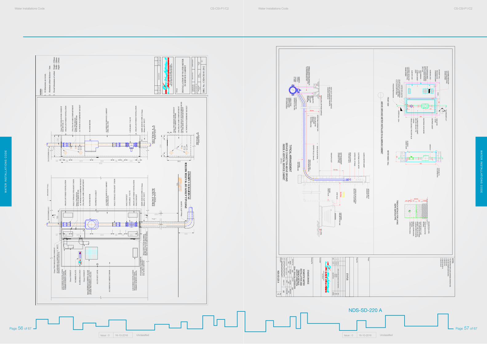
WA
TE
R I
NS
TA
LL
AT
ION
S C
OD
EW
AT
ER
INS
TA
LL
AT
ION
S C
OD
EWater Installations Code CS-CSI-P1/C2Water Installations Code CS-CSI-P1/C2
Issue : 0 16-10-2016 UnclassifiedIssue : 0 16-10-2016 Unclassified
Page 57 of 67Page 56 of 67
NDS-SD-220 A
HEA
D O
F FC
S
DA
TED
RA
WN
BY
12/1
2/20
12
AU
TOC
AD
REF
. No.
:
DES
IGN
ED B
YM
ETER
TEA
M
SCA
LE
REV
.
N.T
.S
APP
RO
VED
BY
DES
CR
IPTI
ON
WA
TER
NET
WO
RK
AFF
AIR
S
TITL
E
REV
.D
ATE
DR
AW
NEN
G.
NEO
PREN
E G
ASK
ET
ALU
MIN
UM
CA
BIN
ET D
OO
R
KA
HR
AM
AA
LO
GO
(830
x300
x230
)A
LUM
INU
M S
ERV
ICE
CA
BIN
ET
BO
UN
DA
RY
WA
LL
WA
TER
MET
ER
LOC
KA
BLE
VA
LVE
NO
TE
S:
MD
PE S
ERV
ICE
PIPE
22-
54m
m
WIT
H S
TAIN
LESS
STE
ELV
ERM
IN S
CR
EEN
(200
x80)
LOU
VER
ED V
ENTI
LATI
ON
80m
m H
OLE
WIT
H R
UB
BER
B
USH
TO
ALL
OW
SM
ALL
ER S
IZE
PIPE
S 2
2-54
(BO
TH S
IDES
)
DR
G. N
o.: C
SD-C
SI-0
1-20
12
INST
AL
LA
TIO
N O
F W
AT
ER
ME
TE
RIN
SE
RV
ICE
CA
BIN
ET
NU
MB
ER P
LATE
MA
LE S
OC
KET
MA
LE S
OC
KET
MA
LE /F
EMA
LE S
TRA
IGH
T U
NIO
N
MA
LE /F
EMA
LE S
TRA
IGH
T U
NIO
N
100x
50 L
OU
VER
ED V
ENTI
LATI
ON
WIT
H S
TAIN
LESS
STE
ELV
ERM
IN S
CR
EEN
(100
x50)
LOU
VER
ED V
ENTI
LATI
ON
250x
100x
230
AM
R C
OM
PAR
TMEN
T
WA
TER
MET
ER
(900
x 30
0x 2
30)
ALU
MIN
UM
SER
VIC
E C
AB
INET
LOC
KA
BLE
VA
LVE
80m
m u
PVC
DU
CT
80m
m u
PVC
DU
CT
MD
PE S
ERV
ICE
PIPE
22-
54m
m
TO C
UST
OM
ER G
.S.T
.TO
CU
STO
MER
G.S
.T.
80m
m u
PVC
ELB
OW
G.L
.
32m
m T
WO
HO
LES
FOR
CO
ND
UIT
32m
m C
ON
DU
IT
ALL
EN K
EY L
OC
K
SEE
DET
AIL
-A
100x
50 L
OU
VER
ED V
ENTI
LATI
ON
100x
50 L
OU
VER
ED V
ENTI
LATI
ON
INST
ALL
ATI
ON
OF
WA
TER
MET
ERIN
SER
VIC
E C
AB
INET
AC
PO
WER
WA
TER
PRO
OF
SOC
KET
NA
M
STA
ND
AR
D A
LUM
INU
M 2
-1½
''B
UTT
HIN
GES
FIX
WIT
H 4
RIV
ETS
STA
ND
AR
D A
LUM
INU
M2-
1½''
BU
TT H
ING
ESFI
X W
ITH
4 R
IVET
S
32m
m T
WO
HO
LES
FOR
CO
ND
UIT
AC
PO
WER
WA
TER
PRO
OF
SOC
KET
16m
m T
WO
HO
LES
WIT
H R
UB
BER
BU
SH
250x
230x
100
AM
R C
OM
PAR
TMEN
T16
mm
TW
O H
OLE
SW
ITH
RU
BB
ER B
USH
250x
100x
230
AM
R C
OM
PAR
TMEN
T16
mm
TW
O H
OLE
S W
ITH
RU
BB
ER B
USH
ON
TH
E SI
DE
OF
CO
MPA
RTM
ENT
100x
50 L
OU
VER
ED V
ENTI
LATI
ON
6mm
GEO
RG
IAN
WIR
ED G
LASS
TO M
ETER
REA
DIN
G F
AC
ILIT
Y(I
NSI
DE
PRO
VID
ED) (
130x
130)
32m
m T
WO
HO
LES
FOR
CO
ND
UIT
ON
TH
E C
AB
INET
FR
AM
E
AC
PO
WER
WA
TER
PRO
OF
SOC
KET
FIEL
D S
ERV
ICES
DEP
AR
TMEN
T
32m
m C
ON
DU
IT
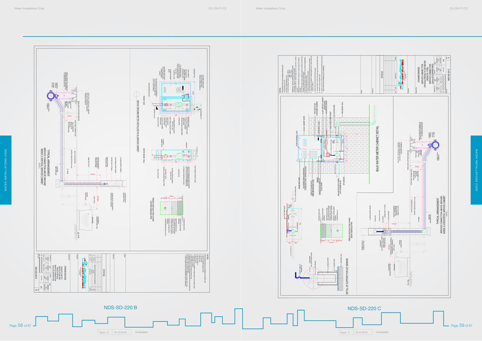
WA
TE
R I
NS
TA
LL
AT
ION
S C
OD
EW
AT
ER
INS
TA
LL
AT
ION
S C
OD
EWater Installations Code CS-CSI-P1/C2Water Installations Code CS-CSI-P1/C2
Issue : 0 16-10-2016 UnclassifiedIssue : 0 16-10-2016 Unclassified
Page 59 of 67Page 58 of 67
NDS-SD-220 CNDS-SD-220 B
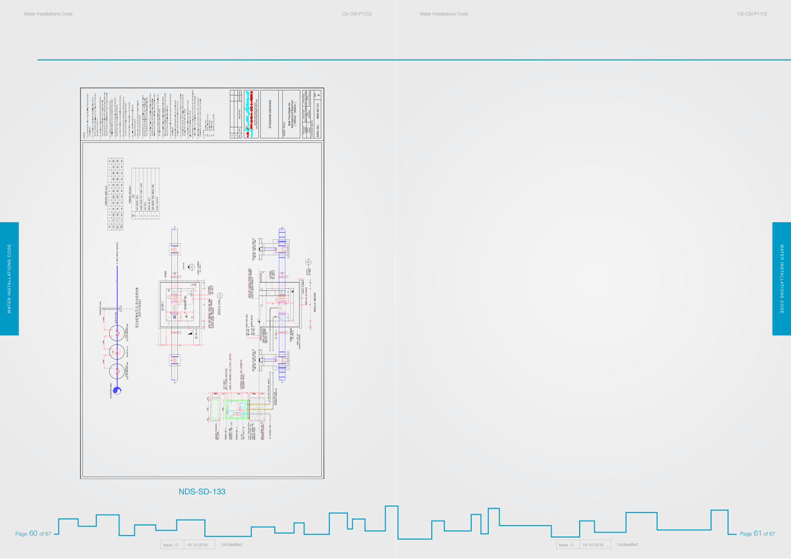
WA
TE
R I
NS
TA
LL
AT
ION
S C
OD
EW
AT
ER
INS
TA
LL
AT
ION
S C
OD
EWater Installations Code CS-CSI-P1/C2Water Installations Code CS-CSI-P1/C2
Issue : 0 16-10-2016 UnclassifiedIssue : 0 16-10-2016 Unclassified
Page 61 of 67Page 60 of 67
NDS-SD-133
WA
TE
R I
NS
TA
LL
AT
ION
S C
OD
EW
AT
ER
INS
TA
LL
AT
ION
S C
OD
EWater Installations Code CS-CSI-P1/C2Water Installations Code CS-CSI-P1/C2
Issue : 0 16-10-2016 UnclassifiedIssue : 0 16-10-2016 Unclassified
Page 63 of 67Page 62 of 67
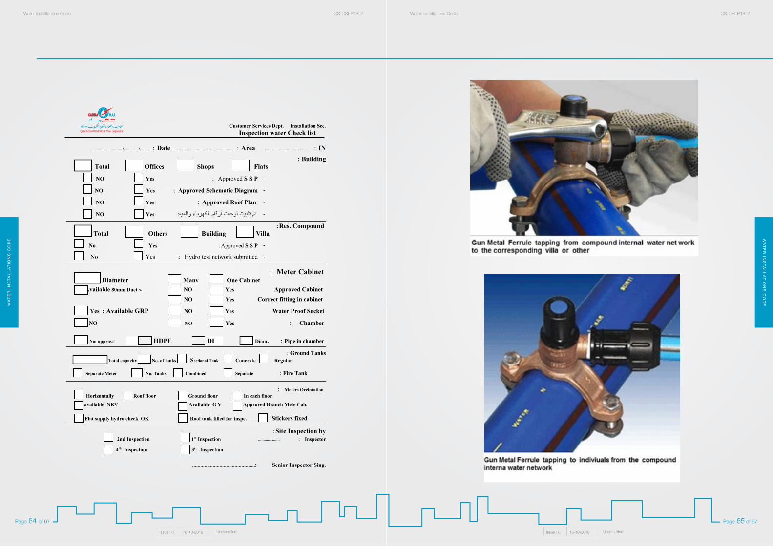
WA
TE
R I
NS
TA
LL
AT
ION
S C
OD
EW
AT
ER
INS
TA
LL
AT
ION
S C
OD
EWater Installations Code CS-CSI-P1/C2Water Installations Code CS-CSI-P1/C2
Issue : 0 16-10-2016 UnclassifiedIssue : 0 16-10-2016 Unclassified
Page 65 of 67Page 64 of 67
Customer Services Dept. Installation Sec. Inspection water Check list
IN :............................................. Area : ........................................................... Date :........../.............../............................
Building : Flats Shops Offices Total
- Approved S S P : Yes NO
- Approved Schematic Diagram : Yes NO
- Approved Roof Plan : Yes NO
Yes NO تم تثبيت لوحات أرقام الكهرباء والمياه -
Res. Compound: Villa Building Others Total
- Approved S S P: Yes No
- Hydro test network submitted : Yes No
Meter Cabinet : One Cabinet Many Diameter
Approved Cabinet Yes NO --Available 80mm Duct .
Correct fitting in cabinet Yes NO
Water Proof Socket Yes NO : Available GRP Yes
Chamber : Yes NO NO
Pipe in chamber : HDPE Not approve
Ground Tanks: Regular Concrete No. of tanks Sectional Tank Total capacity
Fire Tank : Separate Combined No. Tanks Separate Meter
Meters Oreintation : In each floor Ground floor Roof floor Horizontally
Approved Branch Mete Cab. Available G V NRV available
Stickers fixed Roof tank filled for inspc. Flat supply hydro check OK
Site Inspection by: Inspector : .................... Inspection st1 2nd Inspection
Inspection rd3 Inspection th4
Senior Inspector Sing. ..............................................:
DI Diam.
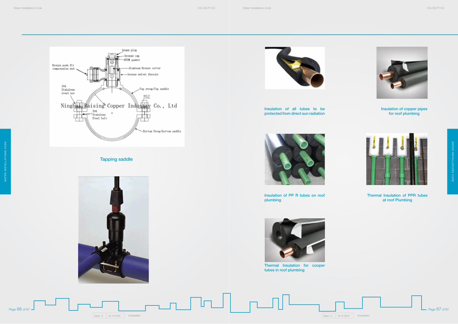
WA
TE
R I
NS
TA
LL
AT
ION
S C
OD
EW
AT
ER
INS
TA
LL
AT
ION
S C
OD
EWater Installations Code CS-CSI-P1/C2Water Installations Code CS-CSI-P1/C2
Issue : 0 16-10-2016 UnclassifiedIssue : 0 16-10-2016 Unclassified
Page 67 of 67Page 66 of 67
Insulation of all tubes to be protected from direct sun radiation
Insulation of PP R tubes on roof plumbing
Thermal Insulation for cooper tubes in roof plumbing
Insulation of copper pipes for roof plumbing
Thermal Insulation of PPR tubes at roof Plumbing
Tapping saddle