emission factor documentation for ap-42 section 4.12 ... · process emissions information. ... amtb...
TRANSCRIPT

Emission

I. Introduction
The EPA's Air Management Technology Branch (AMTB), Research Triangle
Park, North Carolina, is responsible for maintaining the document Compi-
lation of Air Pollutant Emission Factors, AP-42. This document is
supplemented or updated periodically to present the most up-to-date
process emissions information. Subsequent to receiving inquiries about
VOC emissions from processes using polyester resins in the fabrication
of plastics products, AMTB became aware of the report of a study per-
formed in California to develop VOC emission factors for these processes.
Pacific Environmental Services, Inc. (PES) was contracted to review the
available information on this industry and prepare a new AP-42 section
reporting process emission factors (EPA Contract No. 68-02-3887,
Assignment 58, February 1987, and Contract No. 68-02-4393, Assignment
10, October 1987). This report documents the source of the emission
factors that are presented in Section 4.12, Polyester Resin Plastics
Product Fabrication.
II. Fiberglass Fabrication Processes and Emissions
Products made of fiber-reinforced plastics are becoming increas-
ingly prevalent ldue to their favorable strength-to-weight characteris-
tics, corrosion resistance, and ease of molding into a great variety
of shapes and sizes. While general1.y referred to as "fiberglass," some
of these plastics products do not contain fibers (but instead some sort
of powdered or granulated fillers) and many contain fibers other than
glass (carbon and aramid fibers are growing in use). The manufacture
of all of these types of products, h'owever, utilizes unsaturated poly-
ester resin, whiich contains a vinyl-type monomer ingredient (almost
always styrene), and so all of them can be considered under a single
product category. For convenience, the term "fiberglass" can be used
to refer to all types of polyester rlesin plastics products. When these
liquid resins are mixed with a polymerization initiator, or catalyst
(methyl ethyl ketone peroxide and besnzoyl peroxide are common), a
curing
During
state,
volati
resins
process
mixing,
styrene
begins which solidifies the resin/fiber composite.
application and curing, while the resin is in a liquid
evaporates from the surface and constitutes a source of
le organic compound (VOC) emissions. The VOC emissions from some
(vapor-suppressed resins) are reduced due to a lowered styrene
content or through the addition of vapor suppressing additives. While
many facilities rely completely on manual production steps, others are
highly automated, assembly line type operations. The principal
fabrication processes include hand layup, spray layup (or sprayup),
continuous lamination, pultrusion, filament winding, and various closed
molding operations. These processes are briefly described below.
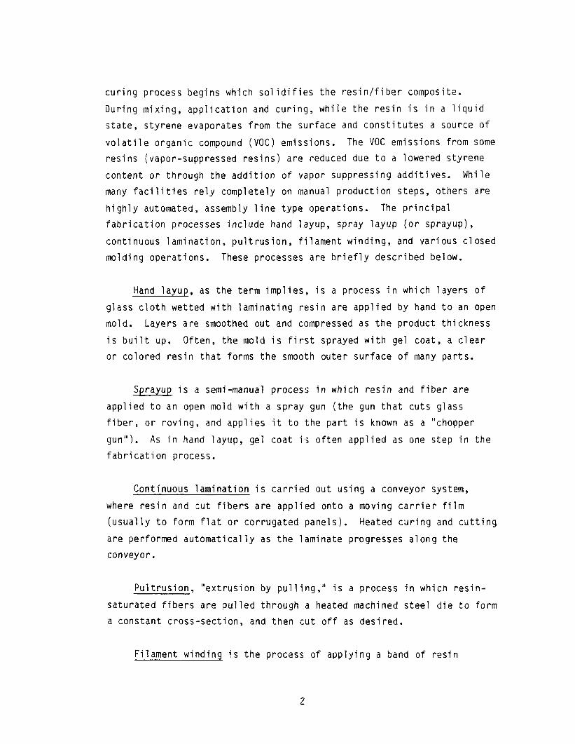
Hand layup, as the term implies,, is a process in which layers of
glass cloth wetted with laminating resin are applied by hand to an open
mold. Layers are smoothed out and compressed as the product thickness
is built up, Often, the mold is first sprayed with gel coat, a clear
or colored resin that forms the smooth outer surface of many parts.
proces. Sprayup is a semi-manual s in which resin and fiber are
applied to an open mold with a spray gun (the gun that cuts glass
fiber, or roving, and applies it to the part is known as a "chopper
gun"). As in hand layup, gel coat is often applied as one step in the
fabrication process.
Continuous lamination is carrield out using a conveyor system,
where resin and Icut fibers are applied onto a moving carrier film
(usually to form flat or corrugated panels). Heated curing and cutting
are performed automatically as the laminate progresses along the
conveyor.
Pultrusion, "extrusion by pulling," is a process in which resin-
saturated fibers are pulled through a heated machined steel die to form
a constant cross-section, and then cut off as desired.
Filament winding is the process of applying a band of resin

impregnated fibers to a rotating mandrel surface in a precise geometric
pattern to form cylindrically shaped parts.
Closed molding operations utilize a completely enclosed mold to
fully define the contours of a part. Synthetic marble for sinks,
countertops, and the like is often produced by a "semi-closed" molding
process, using a resin mix containing fillers, but no reinforcing
fibers. A translucent gel coat is sprayed onto the mold or the
cast product to produce a smooth, glossy surface that simulates natural
marble.
III. Sources of Process and Emission Information
Industry information was collected through a literature search and
through telephone contacts with industry and control agency experts.
The following subsections summarize the principal references and
contacts consulted.
A. Literature Survey
As mentioned in the Introduction, a study was performed in
California in 1981, to survey the industry and develop VOC emission
factors for the key fabrication operations. This study was sponsored
by the California Air Resources Board (CARB), and carried out by Science
Applications, Inc. (SAI). In this study, SAI utilized both previous
emission measurement studies and its own test results from three fabri-
cation plants. The final report on the study, Control Techniques for
Organic Gas Emissions from Fiberglass Impregnation and Fabrication
Processes,I provided useful process information and was the only
significant source of emission factors in the literature survey. Section
IV of this documentation report summarizes the origin of and rationale for
the emission factors presented in the 1981 CARB/SAI report. It should
be noted at this point that most of these factors were not used in
AP-42 Section 4.12 because they were superceded by suggested factors
received in industry comments on the draft section sent out for external
review. (See Section VI for a discussion of these comments and the
3
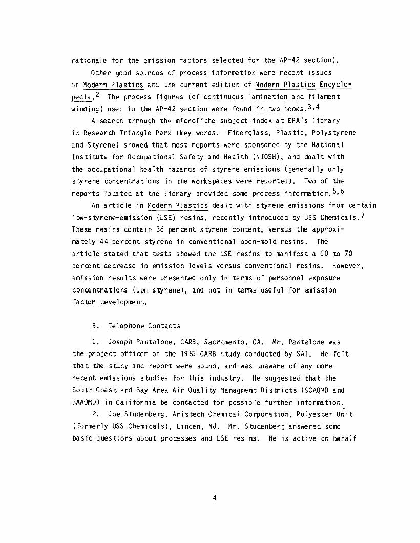
rationale for the emission factors selected for the AP-42 section).
Other good sources of process information were recent issues
of Modern Plastics and the current edition of Modern Plastics Encyclo-
yedia.2 The process figures (of continuous lamination and filament
winding) used in the AP-42 section were found in two books.3*4
A search through the microfiche subject index at EPA's library
in Research Triangle Park (key words: Fiberglass, Plastic, Polystyrene
and Styrene) showed that most reports were sponsored by the National
IInstitute for Occupational Safety and Health (NIOSH), and dealt with
the occupational health hazards of styrene emissions (generally only
:styrene concentrations in the workspaces were reported). Two of the
reports located at the library provided some process information.5s6
An article in Modern Plastics dealt with styrene emissions from certain
low-styrene-emission (LSE) resins, recently introduced by USS Chemical~.~
These resins contain 36 percent styrene content, versus the approxi-
mately 44 percent styrene in conventional open-mold resins. The
(article stated that tests showed the LSE resins to manifest a 60 to 70
percent decrease in emission levels versus conventional resins. However,
'emission results were presented only in terms of personnel exposure
concentrations (ppm styrene), and not in terms useful for emission
factor development.
B. Telephone Contacts
1. Joseph Pantalone, CARB, Sacramento, CA. Mr. Pantalone was
the project officer on the 1981 CARB study conducted by SAI. He felt
that the study and report were sound, and was unaware of any more
recent emissions studies for this industry. He suggested that the
South Coast and Bay Area Air Quality Managment Districts (SCAQMD and
BAAQMD) in California be contacted for possible further information.
2. Joe Studenberg, Aristech Chemical Corporation, Polyester Unit
(formerly USS Chemicals), Linden, NJ. Mr. Studenberg answered some
basic questions about processes and LSE resins. He is active on behalf
4
1
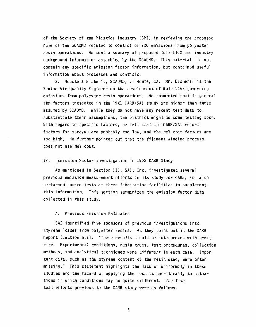
of the Society of the Plastics Industry (SPI) in reviewing the proposed
rule of the SCAQMD related to control of VOC emissions from polyester
resin operations. He sent a summary of proposed Rule 1162 and industry
background information assembled by the SCAQMD. This material did not
contain any specific emission factor information, but contained useful
information about processes and controls.
3. Moustafa Elsherif, SCAQMD, El Monte, CA. Mr. Elsherif is the
Senior Air Quality Engineer on the development of Rule 1162 governing
emissions from polyester resin operatilons. He commented that in genera
the factors presented in the 1981 CARB/SAI study are higher than those
assumed by SCAQMD. While they do not have any recent test data to
substantiate their assumptions, the Di.strict might do some testing soon
With regard to specific factors, he felt that the CARB/SAI report
factors for sprayup are probably too low, and the gel coat factors are
too high. He further pointed out that the filament winding process
does not use gel coat.
IV. Emission Factor Investigation in 1982 CARB Study
As mentioned in Section III, SAI, Inc. investigated several
plrevious emission measurement efforts in its study for CARB, and also
performed source tests at three fabrication facilities to supplement
this information. This section summarizes the emission factor data
collected in this study.
A. Previous Emission Estimates
SAI identified five sponsors of previous investigations into
styrene losses from polyester resins. As they point out in the CARB
report (Section 5.1): "These results should be interpreted with great
care. Experimental conditions, resin @pes, test procedures, collection
methods, and analytical techniques were different in each case. Impor-
tant data, such as the styrene content of the resin used, were often
missing." This statement highlights the lack of uniformity in these
studies and the hazard of applying the results uncritically to situa-
tions in which conditions may be quite different. The five
test efforts previous to the CARB study were as follows.
5

1. Dade County, Florida. These studies, reported in 1968, involved
a hand layup procedure performed in the lab (vapor-suppressed resin)
and a set of tests at a fabrication pl,ant. The resin styrene percentage
i'n the lab tests was not reported, but could be inferred with only
small uncertainty from the brand name of the resin. Only one field
test, on a gel coat spray gun operation, was considered complete enough
I;0 use.
2. Bay Area AQMD, California. Reports on emission tests at six
fabrication facilities between 1974 and 1978 were reviewed. As SAI
plaints out, "the purpose of these tests was to verify compliance with
hourly and daily emission standards, not to develop emission factors."
For most tests, the styrene percentage in the resin had to be assumed.
All operations in these tests involved spray gun and/or chopper gun
application of resin and gel coat.
3. Ashland Chemical Company, Columbus, Ohio. Ashland Chemical
performed lab tests (undated) to measure weight loss from various
resin/glass formulations, including laminating, casting, and filament
winding resins. Several of the resins tested contained vapor suppres-
sants. The CARB report cautions, "As with the other experiments
reported here, these data should be interpreted with care. Informa-
tion on experimental conditions is inadequate to permit repetition,
alnd the extent to which they simulate actual operations is unknown."
4. Shasta County, California. In these lab tests, performed in
1!378, the weight loss due to organic vapor emissions was measured for
glass plates covered with various layers of gel coat, resin, and glass
fibers. The styrene percentage in the resins was assumed by SAI with
a fairly high degree of confidence.
5. Kingston Polytechnic Studies, England. These were rather
thorough lab tests in which the styrene losses from hand layup lami-
nates were measured gravimetrically. The investigators controlled
and noted the ambient temperature, wind speed, amount of hand rolling,
6

glass reinforcement type, and styrene and wax (suppressant) concentra-
tions.
Table 1, adapted from CARB/SAI report Table 5.1-1, shows the
emission factors calculated by SAI from these studies. Note that the
studies cover only the hand layup and sprayup processes. Emission
factor estimates for the remaining fabrication processes are derived
from source tests performed by SAI during the course of the CARB/SAI
study.
B. SAI Source Tests
To complement previous studies, which covered only the manual
hand layup and sprayup processes, SAI Iundertook a field sampling program
at three fabrication facilities.
Facility 1 - Continuous lamination plant, 3/I8-19/81. This plant
makes fiberglass panels on a production assembly line consisting of
an impregnation table, a gas-fired curing oven, and a product cutting
zone. Emissions from the impregnation table are ducted to an incinerator
control device, and an ESP removes particulate matter from air collected
at several points in the production line. Several ventilation exhaust
ducts were sampled, including the incirierator exhaust, to produce both
uncontrolled and controlled emission factors. Tests were run during
t,he use of two different resins, one containing 40 percent styrene and
the other containing a mix of 35 percent styrene and 5 percent methyl
methacrylate (MMA).
Styrene sampling was performed using a Foxboro Instruments Model
128 OVA organic vapor analyzer in combination with charcoal tube traps.
An HP Model 5730A gas chromatograph was used to analyze the contents of
the charcoal traps. Individual emission factors were added together to
produce ranges for both uncontrolled and controlled situations. It
should be noted that SAI considered results from both the straight
styrene resin and the styrene/MMA blend resin when selecting the final
emission factor range for this process. The uncontrolled emission
7

TABLE 1. EMISSION FACTORS ESTIMATED BY SAI FROM PREVIOUS STYRENE LOSS STUDIES
Test Test Emission Factor, Sourcea Processb Resin TypeC Locationd percente
H H H H H H H H H H H H
L L 8.5 - 10.5 L L 15.6 - 35.4 L L 8 L* L 5.6 - 6.3 L* L 1.9 - 2.6 L* L 13.6 - 19.6 G L 47 FW L 71 - 82 FW* L 16 FR L 6.6 C L 3.8 - 4.1 C* L 1.0 - 1.4
L L
F 27 F >12g
8 - 18 16 - 25
13 26 - 28
7 - 12f 24 - 38
"Test source: 1 = Dade County, 2 = Bay Area, 3 = Ashland Chemical, 4= Shasta County, 5 = Kingston Polytechnic.
*'Process: H = hand layup, S = sprayup, C = chopper gun.
(:Resin type: L = laminating, G = gel coat, FW = filament winding, FR = fire retardant, C = casting. Asterisk indicates a vapor-suppressing type resin.
('Test location: L = laboratory, F = field.
eEmission factor = 100 x (styrene emissions/styrene input).
fThese emission factors are for laminating resin and gel coat combined.
gExhaust air in this test was diluted to an unknown extent, so this factor represents a lower bound.
8
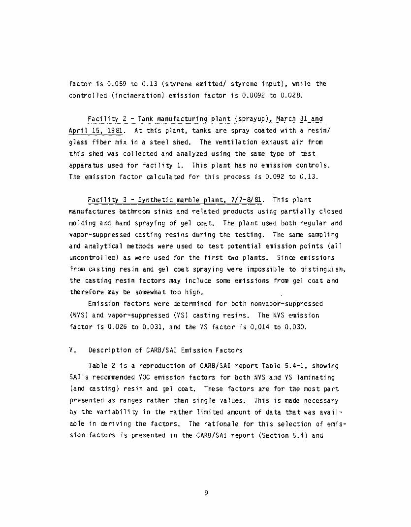
factor is 0.059 to 0.13 (styrene emitted/ styrene input), while the
controlled (incineration) emission factor is 0.0092 to 0.028.
Facility 2 - Tank manufacturing plant (sprayup), March 31 and
April 15, 1981. At this plant, tanks are spray coated with a resin/
glass fiber mix in a steel shed. The ventilation exhaust air from
this shed was collected and analyzed using the same type of test
apparatus used for facility 1. This plant has no emission controls.
The emission factor calculated for thi:s process is 0.092 to 0.13.
Facility 3 - Synthetic marble plant, 7/7-8/81. This plant
manufactures bathroom sinks and related products using partially closed
molding and hand spraying of gel coat. The plant used both regular and
vapor-suppressed casting resins during the testing. The same sampling
and analytical methods were used to test potential emission points (all
uncontrolled) as were used for the first two plants. Since emissions
from casting resin and gel coat spraying were impossible to distinguish,
the casting resin factors may include some emissions from gel coat and
therefore may be somewhat too high.
Emission factors were determined for both nonvapor-suppressed
(NVS) and vapor-suppressed (VS) casting resins. The NVS emission
factor is 0.026 to 0.031, and the VS factor is 0.014 to 0.030.
v ., Description of CARB/SAI Emission Factors
Table 2 is a reproduction of CARB/SAI report Table 5.4-1, showing
SAI’s recommended VOC emission factors for both NVS a;id VS laminating
(and casting) resin and gel coat. These factors are for the most part
presented as ranges rather than single values. This is made necessary
by the variability in the rather limited amount of data that was avail-
able in deriving the factors. The rationale for this selection of emis-
sion factors is presented in the CARB/SAI report (Section 5.4) and
9
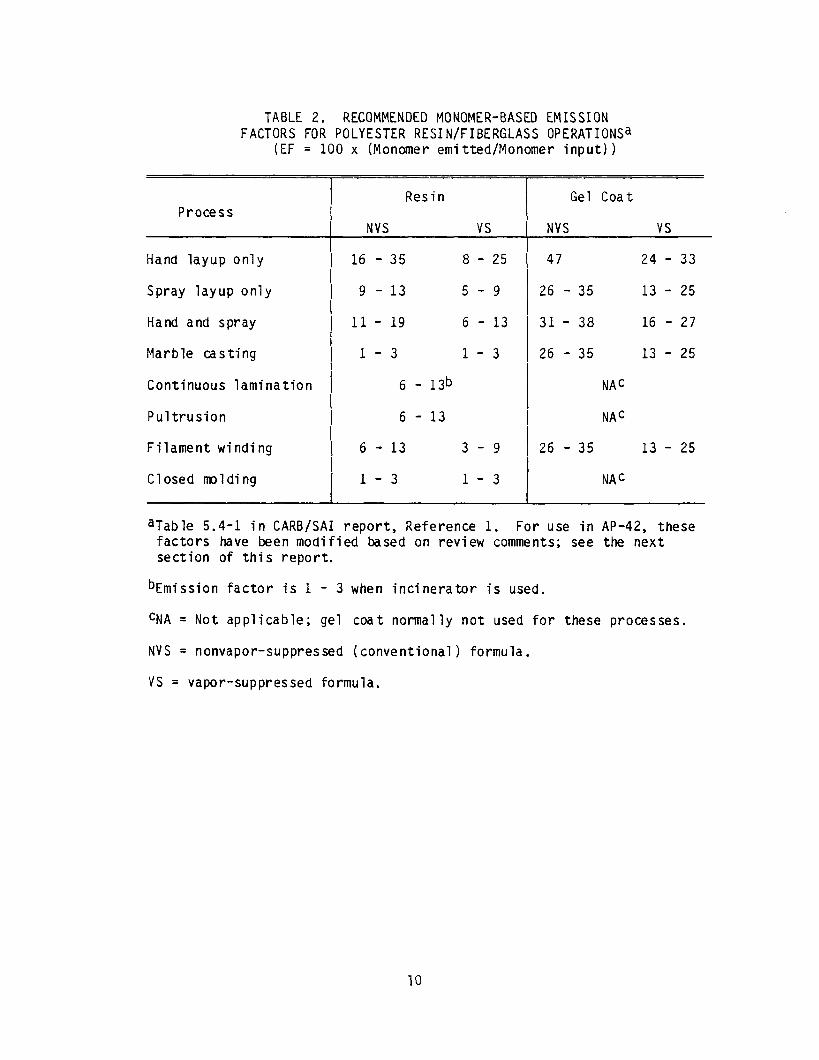
TABLE 2. RECOMMENDED MONOMER-BASED EMISSION FACTORS FOR POLYESTER RESIN/FIBERGLASS OPERATIONSa
(EF = 100 x (Monomer emitted/Monomer input))
Process
Hand layup only
Spray layup only
Hand and spray
Marble casting
Continuous lamination
Pultrusion
Filament winding
Closed molding
Resin Gel Coat
NVS vs NVS vs
16 - 35 8 - 25 47 24 - 33
9 - 13 5-9 26 - 35 13 - 25
ll- 19 6 - 13 31- 38 16 - 27
l-3 l-3 26 - 35 13 - 25
6 - 13b NAC
6 - 13 NAC
6 - 13 3-9 26 - 35 13 - 25
1-3 l-3 NAc
aTable 5.4-l in CARB/SAI report, Reference 1. For use in AP-42, these factors have been modified based on review comments; see the next section of this report.
bEmission factor is 1 - 3 when incinerator is used.
CNA = Not applicable; gel coat normally not used for these processes.
NVS = nonvapor-suppressed (conventional) formula.
vs = vapor-suppressed formula.
10
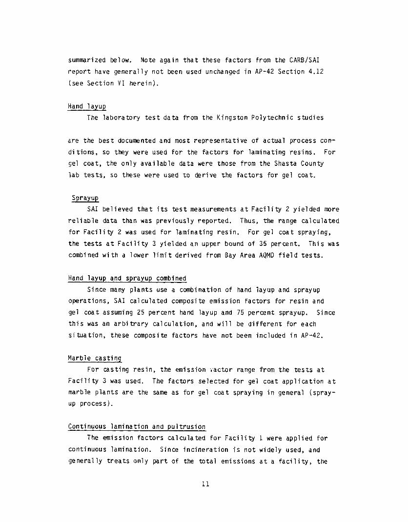
.summarized below. Note again that these factors from the CARB/SAI
report have generally not been used unchanged in AP-42 Section 4.12
(see Section VI herein).
Hand layup
The laboratory test data from the Kingston Polytechnic studies
are the best documented and most representative of actual process con-
ditions, so they were used for the factors for laminating resins. For
gel coat, the only available data were those from the Shasta County
lab tests, so these were used to derive the factors for gel coat.
Sprayup
SAI believed that its test measurements
reliable data than was previously reported.
at Facility 2 yielded more
Thus, the range calculated
for Facility 2 was used for laminating resin. For gel coat spraying,
the tests at Facility 3 yielded an upper bound of 35 percent. This was
combined with a lower limit derived from Bay Area AQMD field tests.
Hand layup and sprayup combined
Since many plants use a combination of hand layup and sprayup
operations, SAI calculated composite emission factors for resin and
gel coat assuming 25 percent hand layup and 75 percent sprayup. Since
this was an arbitrary calculation, and 'will be different for each
situation, these composite factors have not been included in AP-42.
Marble casting
For casting resin, the emission Factor range from the tests at
Facility 3 was used. The factors selected for gel coat application at
marble plants are the same as for gel coat spraying in general (spray-
up process).
Continuous lamination and pultrusion
The emission factors calculated for Facility 1 were applied for
continuous lamination. Since incineration is not widely used, and
generally treats only part of the total emissions at a facility, the
11

controlled emission factor referred to in the table footnote has not
been included in AP-42. Since continuous lamination and pultrusion are
:somewhat similar processes, and specific test data for pultrusion were
unavailable, SAI assigned the same emission factor ranges to pultrusion.
IEmission factors for gel coat were not assigned because gel coat is not
normally used in these two operations.
IFilament winding
While laboratory tests with filament winding resins have been
performed (Ashland Chemical), no actual process data from this operation
'are available. Therefore, SAI assigned the emission factors for the
most similar process, continuous lamination, to filament winding.
[Closed molding processes
As with filament winding, no specific emission test data were
(available for bag molding, matched metal molding, and other closed
molding operations. Therefore, the emission factors for marble casting
(a semi-closed process) were applied to closed molding. Emission
factors for gel coat were not assigned because gel coat is not normally
used in these operations.
VI. Selection of Final Emission Factors
On August 13, 1987, a draft of the new AP-42 Section 4.12 was sent
to several technical experts at State and local agencies, an environmental
group, the ASTM, and a resin producer, for their comments on the draft
(emission factors. The draft Factors reflected those presented in the
1981 CARB/SAI report discussed in Sectons IV and V of this documentation
'report. The resin producer (Aristech) circulated the draft to the
Polyester Resin Technical Committee of the Society for the Plastics
Industry (SPI), and as a result comments were collected from several
other companies, including Ashland Chemicals, Freeman Chemicals,
Interplastics, Koppers Company, Norac, Owens Corning Fiberglas, Reichhold
~Chem icals, and S ilmar. The comments received addressed several areas
12
of technical content in the descriptive text, as well as the emission
factors themselves.
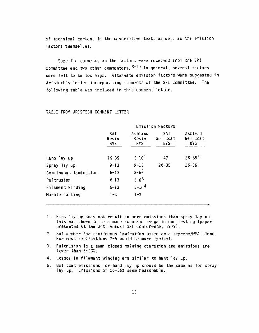
Specific comments on the factors were received from the SPI
Committee and two other comrnenters. 8-10 In general, several factors
were felt to be too high. Alternate emission factors were suggested in
Aristech's letter incorporating comments of the SPI Committee. The
following table was included in this clomment letter.
TABLE FROM ARISTECH COMMENT LETTER
Emission Factors
SAI Resin
NVS
Ashland SAI Ashland Resin Gel Coat Gel Coat
NVS NVS NVS --
Hand lay up 16-35 s-101 47 26-355
Spray lay up 9-13 9-13 26-35 26-35
Continuous lamination 6-13 2-62
Pultrusion 6-13 2-63
Filament Winding 6-13 S-104
Marble Casting l-3 1 ,-3
1. Hand lay up does not result in more emissions than spray lay up. This was shown to be a more accurate range in our testing (paper presented at the 34th Annual SPI Conference, 1979).
2. SAI number for continuous lamination based on a styrene/MMA blend. For most applications 2-6 would be more typical.
3. Pultrusion is a semi closed molding operation and emissions are lower than 6-13%.
4. Losses in filament winding are similar to hand lay up.
5. Gel coat emissions for hand lay up should be the same as for spray lay up. Emissions of 26-35% seem reasonable.
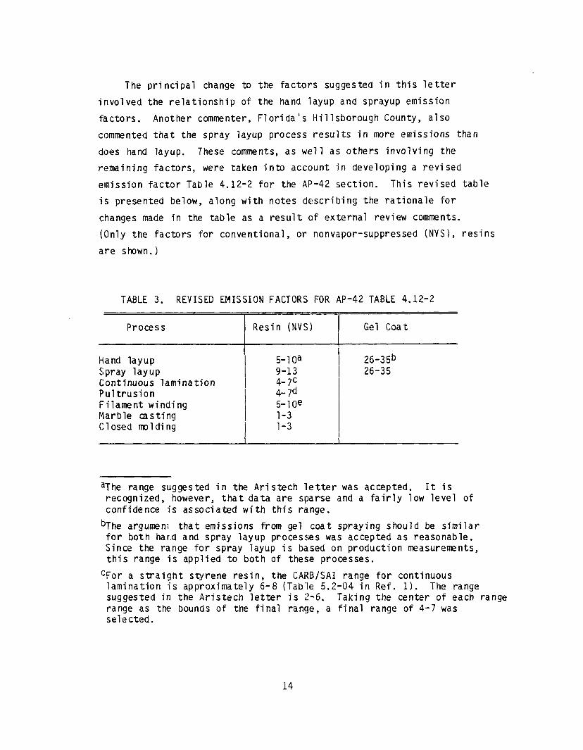
The principal change to the factors suggested in this letter
involved the relationship of the hand layup and sprayup emission
factors. Another commenter, Florida's Hillsborough County, also
commented that the spray layup process results in more emissions than
does hand layup. These comments, as well as others involving the
remaining factors, were taken into accolunt in developing a revised
emission factor Table 4.12-2 for the AP-42 section. This revised table
is presented below, along with notes defscribing the rationale for
changes made in the table as a result of external review comments.
(Only the factors for conventional, or nonvapor-suppressed (NVS), resins
are shown.)
TABLE 3. REVISED EMISSION FACTORS FOR AP-42 TABLE 4.12-2
Process
Hand layup Spray layup Continuous lamination Pultrusion Filament winding Marble casting Closed molding
r t I I L
Resin (NVS)
s-10a 9-13 4-7c 4-7d s-10e l-3 l-3
T- t
L
Gel Coat
26-35b 26-35
aThe range suggested in the Aristech letter was accepted. It is recognized, however, that data are sparse and a fairly low level of confidence is associated with this range.
bThe argument that emissions from gel coat spraying should be similar for both har.d and spray layup processes was accepted as reasonable. Since the range for spray layup is based on production measurements, this range is applied to both of these processes.
CFor a straight styrene resin, the CARB/SAI range for continuous lamination is approximately 6-8 (Table 5.2-04 in Ref. 1). The range suggested in the Aristech letter is 2-6. Taking the center of each range range as the bounds of the final range, a final range of 4-7 was selected.
14

dThe range for continuous lamination is assumed to apply to pultrusion. eThe suggestion in the Aristech letter that filament winding emissions
are similar to emissions from hand layup was accepted.
VII. References*
1.
2.
3.
4.
5.
6.
7.
;3 .
9 .
1 0 .
M.B. Rogozen, Control Techniques for Organic Gas Emissions from Fiberglass Impregnation and Fabrication Processes, Science Appli- cations, Inc., Los Angeles, CA. Prepared for California Air Resources Board (GARB), Sacramento, CA, June 1982.
r/r;E,~. - PB 82 -ca-m9 Modern Plastics Encyclopedia, 1986-1987, Vol. 63, No. lOA, October 1986.
R.N. Shreve and J.A. Brink, Jr., Chemical Process Industries, Fourth Ed., McGraw-Hill, 1977.
C.A. Brighton, G. Pritchard and G.A. Skinner, Technology and Environmental Aspects, Applied Ltd., London, 1979.
Styrene Polymers: Science Publishers,
M.S. Crandall, Extent of Exposure to Styrene in the Reinforced Plastic Boat Making Industry, National Institute for Occupational Safety and Health (NIOSH) , P ublication No. 82-110, Cincinnati, OH, March 1982.
Criteria for a Recommended Standard . . . Occupational Exposure to St rene, National Institute for Occupational Safety and Health .7-&iiL Publication No. 83-119, September 1983.
L. Walewski and S. Stockton, "Low-Styrene-Emission Laminating Resins Prove It in the Workplace," Modern Plastics, Vol. 62, No. 8, p. 78-80, August 1985.
Written communication with enclosure from R.C. Lepple, Aristech Chemical Corporation, Linden, NJ, to A.A. MacQueen, U.S. Environmental Protection Agency, Research Triangle Park, NC, September 16, 1987. (Cover letter from J .E. Studenberg, Aristech, to A.A. MacQueen, September 16, 1987.)
Written communication with attachment from E.G. McCune, North Carolina Department of Natural Resources and Community Development, Raleigh, NC, to A.A. MacQueen, U..S. Environmental Protection Agency, Research Triangle Park, NC, September 1, 1987.
Written communication from H.R. Lue, Hillsborough County (Florida) Environmental Protection Commission, Tampa, FL, to A.A. MacQueen, U.S. Environmental Protection Agency, Research Triangle Park, NC, September 16, 1987.
*Note: All of these references have been placed in the Section 4.12, AP-42 files of AMTB, 1J.S. EPA, Research Triangle Park, NC.
15
APPENDIX A
AP-42 SECTION 4.12: POLYESTER RESIN
PLASTICS PRODUCT FABRICATION

4.12 POLYESTER RESIN PLASTICS PRODUCT FABRICATION
4.12.1 General Descriptionls2
A growing number of products are fabricated from liquid polyester resin reinforced with glass fibers and extended with various inorganic filler materials such as calcium carbonate, talc, mica or small glass spheres. These composite materials are often referr(ed to as fiberglass reinforced plastic (FRP), or simply "fiberglass". The Society Of The Plastics Industry designates these materials as "reinforced plastics/composites" (Rl?/C). Also, advanced reinforced plastics products are 'now formulated with fibers other than glass, such as carbon, aramid and aramid/carbon hybrids. In some processes, resin products are fabricated without fibers. One major product usin,g resins with fillers but no reinforcing fibers is the synthetic marble used in manufacturing bathroom countertops, sinks and related items. Other applications of nonreinforced resin plastics include automobile body filler, bowling balls and coatings.
Fiber reinforced plastics products have a wide range of application in industry, transportation, home and recreation. Industrial uses include stor- age tanks, skylights, electrical equipment, ducting, pipes, machine compo- nents, and corrosion resistant structural (and process equipment. In transportation, automobile and aircraft ap,plications are increasing rapidly. Home and recreational Items include bathroom tubs and showers, boats (build- ing .and repair), surfboards and skis, helmets, swimming pools and hot tubs, and a variety of sporting goods.
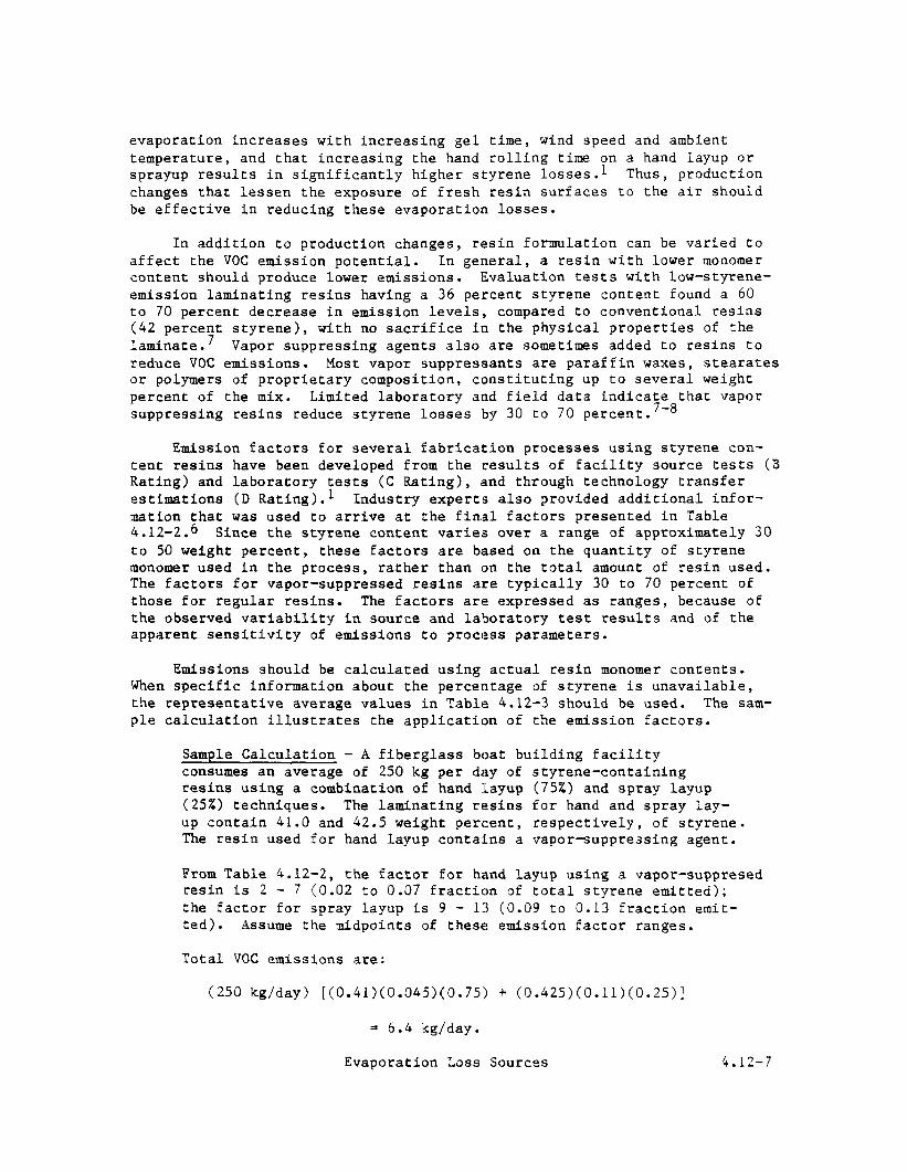
The thermosetting polyester resins considered here are complex polymers resulting from the cross-linking reaction 'of a liquid unsaturated polyester with a vinyl type monomer, most often styrlene. The unsaturated polyester is formed from the condensation reaction of an unsaturated dibasic acid or anhyldride, a saturated dibasic acid or anhydride, and a polyfunctional alcohol. Table 4.12-1 lists the most common compounds used for each compo- nent of the polyester "backbone", as well *as the principal cross-linking mono'mers. The chemical reactions that form both the unsaturated polyester and the cross-linked polyester resin are s:hown in Figure 4.12-l. The emis- sion factors presented here apply to fabrication processes that use the finished liquid resins (as received by fabricators from chemical manufac- turers), and not to the chemical processes used to produce these resins. (See Chapter 5, Chemical Process Industry.)
In order to be used in the fabrication of products, the liquid resin must be mixed with a catalyst to initiate polymerization into a solid thermo- set. Catalyst concentrations generally range from 1 to 2 percent by original weight of resin; within certain limits, the higher the catalyst concentration, the faster the cross-linking reaction proceeds. Common catalysts are organic peroxides, typically methyl ethyl ketone peroxide or benzoyl peroxide. Resins may contain inhibitors, to avoid se.Lf curing during resin storage, and promoters, to allow polymerization to (occur at lower temperatures.
Evaporation Loss Sources 4.12-1

TABLE 4.12-1. TYPICAL COMPONENTS OF RESINS
-5-- To Form the Unsaturated Polyester
Unsaturated Acids -
Maleic anhydride Fumaric acid
Saturated Acids
Phthalic anhydride Isophthalic ac:id Adipic acid
Polyfunctional Alcohols
Propylene glycol Ethylene glycol Diethylene glycol Dipropylene glycol Neopentyl glycol Pentaerythritol
Cross-linking Agents (Monomers)
Styrene Methyl methacrylate Vinyl toluene Vinyl acetate Diallyl phthalate Acrylamide 2-ethyl hexylacrylate
The polyester resin/fiberglass industry consists of many small faci- lities (such as boat repair and small contract firms) and relatively few large firms that consume the major fraction of the total resin. Resin usage at these operations ranges from less than 5,000 kilograms per year to over 3 million kilograms per year.
Reinforced plastics products are fabricated using any of several processes, depending on their size, shape and other desired physical characteristics. The principal processes include hand layup, spray layup (sprayup), continuous lamination, pultrusi.on, filament winding and various closed molding operations.
Hand layup, using primarily manual techniques combined with open molds, is the simplest of the fabrication processes. Here, the reinforce- ment is manually fitted to a mold wetted with catalyzed resin mix, after which it is saturated with more resin. The reinforcement is in the form of either a chopped strand mat, a woven fabric or often both. Layers of reinforcement and resin are added to build the desired laminate thickness. Squeegees, brushes and rollers are used to smooth and compact each layer as it is applied. A release agent is usually first applied to the mold to facilitate removal of the composite. This is often a wax, which can be treated with a water soluble barrier coat such as polyvinyl alcohol to promote paint adhesion on parts that are to be painted. In many operations,
4.12-2 EMISSION FACTORS

0 0 B C-O-C@ I 0 P
ne”C = kH + 2nsHOH2C - CH2OH t n%;o;E ---C
0 \
Maleic anhydride
Ethylene ~IVCOI
Phthalic anhydride
I I
0 0 0 0 0 0 0 0 E E E-0-CH2-CH2-04 E-0-CH2-CH2-04
Y Y \ I \ I
C-0-CH2-CH2-O- C-0-CH2-CH2-O- - -
0 0 \/ \/ HL = LH HL = LH I n
Unsaturated polyester
REACTION 2
0 II 0 0
Cll2 = CH - 0 + “pn;ytyred 0 - I-c*,-EH2-0-~-c*-~*-~- 0-1~-~“2-0-k Q-!-~-jn I
Styrene H-C-H
0
,-o-c-(-J t:
H-k-0
-C-0-CH2-CH2-0-$H-CH- -O-CH2-CH2-)n t
O HA”
H-i ,-0 Cross-linked polyester resin
Figure 4.12-I. Typical reactions for unsaturated polyester and polyester resin formation.
the mold is first sprayed with gel coat, a clear or pigmented resin mix that forms the smooth outer surface of many products. Gel coat spray systems consist of separate sources of resin and catalyst, with an airless hand spray gun that mixes them together into an atomized resin/catalyst stre,am. Typical products are boat hulls and decks, swimming pools, bathtubs and showers, electrical consoles and automobile components.
Spray layup, or *sprayup", is another open mold process, differing from hand layup in that it uses mechanical spraying and chopping equipment for depositing the resin and glass reinforcement. This process allows a greater production rate and more uniform parts than does hand layup, and often uses more complex molds. As in hand layup, gel coat is frequently applied to the mold before fabrication to produce the desired surface qualities. It is common practice to combine hand layup and sprayup operations.
For the reinforced layers, a device is attached to the sprayer system to chop glass fiber "roving" (uncut fiber) into predetermined lengths and pro- ject it to merge with the resin mix stream. The stream precoats the chop, and both are deposited simultaneously to the desired layer thickness on the mold surface (or on the gel coat that was applied to the mold). Layers are built up and rolled out on the mold as necessary to form the part. Products manufactured by sprayup are similar to those made by hand layup, except that more uniform and complex parts can generall:y be produced more efficiently with sprayup techniques. However, compared to hand layup, more resin generally is used to produce similar parts by spray layup because of the inevitable over- spray of resin during application.
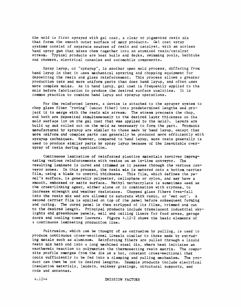
Continuous lamination of reinforced plastics materials involves impreg- nating various reinforcements with resins on an in-line conveyor. The resulting laminate is cured and trimmed as it passes through the various con- veyor zones. In this process, the resin mix is metered onto a bottom carrier film, using a blade to control thickness. This film, which defines the pa- nel's surface, is generally polyester, cellophane or nylon, and may have a smooth, embossed or matte surface. Methyl methacrylate is sometimes used as the cross-linking agent, either alone or in combination with styrene, to increase strength and weather resistance. Chopped glass fibers free-fall into the resin mix and are allowed to saturate with resin, or "wet out". A second carrier film is applied on top of the panel before subsequent forming and curing. The cured panel is then stripped of its films, trimmed and cut to the desired length. Principal products include translucent industrial sky- lights and greenhouse panels, wall and ceiling liners for food areas, garage doors and cooling tower louvers. Figure 4.12-2 shows the basic elements of a cont:Lnuous laminating production line.
Pultrusion, which can be thought of as extrusion by pulling, is used to produce continuous cross-sectional lineals similar to those made by extrud- ing metals such as aluminum. Reinforcing fibers are pulled through a liquid resin mix bath and into a long machined steel die, where heat initiates an exothermic reaction to polymerize the thermosetting resin matrix. The compo- site profile emerges from the die as a hot, constant cross-sectional that cools sufficiently to be fed into a clamping and pulling mechanism. The pro- duct can then be cut to desired lengths. Example products include electrical insulation materials, ladders, walkway gratings, structural supports, and rods and antennas.
4.12-4 EMISSION FACTORS
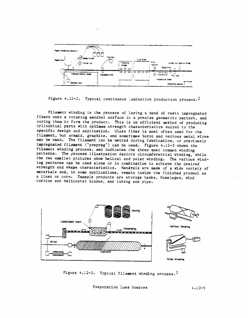
Figure 4.12-2. Typical continuous lamination production proce~s.~
Filament winding is the process of Laying a band of resin impregnated fibers onto a rotating mandrel surface in a precise geometric pattern, and curing them to form the product. This is an efficient method of producing cylindrical parts with optimum strength characteristics suited to the specific design and application. Glass fiber is most often used for the filament, but aramid, graphite, and sometimes boron and various metal wires may be used. The filament can be wetted during fabrication, or previously impregnated filament ("prepreg") can be used. filament winding process,
Figure 4.12-3 shows the
patterns. and indicates the three most common winding
The process illustration depicts circumferential winding, while the two smaller pictures show helical and polar winding. The various wind- ing patterns can be used alone or in combination to achieve the desired strength and shape characteristics. materials and, in some applications,
Mandrels are made of a wide variety of
a liner or core. remain inside the finished product as
Example products are storage tanks, fuselages, wind turbine and helicopter blades, and tubing and pipe.
rovtng
/
Catsbed rem
Polar YIndin
Figure 4.12-3. Typical filament winding process.3
Evaporation Loss Sources 4.12-5

Closed, such as compression or injection, molding operations involve the use of two matched dies to define the entire outer surface of the part. When closed and filled with a resin mix, the matched die mold is subjected to heat and pressure to cure the plastic. For the most durable production configuration, hardened metal dies are used (matched metal molding). Another closed molding process is vacuum or pressure bag molding. In bag molding, a hand layup or sprayup is covered with a plastic film, and vacuum or pressure is applied to rigidly define the part and improve surface quality. The range of closed molded parts includes tool and appliance housings, cookware, brackets and other small parts, and automobile body and electrical components.
Synthetic marble casting, a large segment of the resin products indus- try, involves production of bathroom sinks, vanity tops, bathtubs and accessories using filled resins that have the look of natural marble. No reinforcing fibers are used in these products. Pigmented or clear gel coat can either be applied to the mold itself or sprayed onto the product after casting to simulate the look of natural polished marble. Harble casting can be an open mold process, or it may be considered a semiclosed process if cast parts are removed from a closed mold for subsequent gel coat spray- ing.
4.12.2 Emissions And Controls
Organic vapors consisting of volati18e organic compounds (VOC) are emit- ted from fresh resin surfaces during the fabrication process and from the use of solvents (usually acetone) for cle,anup of hands, tools, molds and spr,aying equipment. Cleaning solvent emilssions can account for over 36 percent of the total plant VOC emissions.4 There also may be some release of particulate emissions from automatic fiber chopping equipment, but these emissions have not been quantified.
Organic vapor emissions from polyester resin/fiberglass fabrication processes occur when the cross-linking agent (monomer> contained in the liquid resin evaporates into the air during resin application and curing. Styrene, methyl methacrylate and vinyl toiluene are three of the principal monomers used as cross-linking agents. Styrene is by far the most common. Other chemical components of resins are emitted only at trace levels, because they not only have low vapor pressures but also are substantially converted to polymers.5'6
Since emissions result from evaporation of monomer from the uncured resin, they depend upon the amount of resin surface exposed to the air and the time of exposure. Thus, the potential for emissions varies with the manner in which the resin is mixed, applied, handled and cured. These fac- tors vary among the different fabrication processes. For example, the spray layup process has the highest potential for VOC emissions because the atomization of resin into a spray creates an extremely large surface area from which volatile monomer can evaporate. By contrast, the emission potential in synthetic marble casting and closed molding operations is considerably lower, because of the lower monomer content in the casting resins (30 to 38 percent, versus about 43 percent) and of the enclosed nature of these molding operations. It has been found that styrene
A.12-6 EMISSION FACTORS
evaporation increases with increasing gel time, wind speed and ambient temperature, and that increasing the hand rolling time on a hand layup or sprayup results in significantly higher styrene losses.1 Thus, production changes that lessen the exposure of fresh resin surfaces to the air should be effective in reducing these evaporation losses.
In addition to production changes, resin formulation can be varied to affect the VOC emission potential. In general, a resin with lower monomer content should produce lower emissions. Evaluation tests with low-styrene- emission laminating resins having a 36 percent styrene content found a 60 to 70 percent decrease in emission levels, compared to conventional resins (42 percent styrene), laminate.7
with no sacrifice in the physical properties of the Vapor suppressing agents also are sometimes added to resins to
reduce VOC emissions. Most vapor suppressants are paraffin waxes, stearates or polymers of proprietary composition, constituting up to several weight percent of the mix. Limited laboratory and field data indica$e*that vapor suppressing resins reduce styrene losses by 30 to 70 percent. -
Emission factors for several fabrication processes using styrene con- tent resins have been developed from the results of facility source tests (B Rat.ing) and laboratory tests (C Rating), estimations (D Rating).l
#and through technology transfer Industry expert,s also provided additional infor-
mation that was used to arrive at the final factors presented in Table 4.12-2.6 Since the styrene content varies over a range of approximately 30 to 50 weight percent, these factors are based on the quantity of styrene monomer used in the process, rather than on the total amount of resin used. The factors for vapor-suppressed resins are typically 30 to 70 percent of those for regular resins. The factors are expressed as ranges, because of the observed variability in source and laboratory test results and of the apparent sensitivity of emissions to process parameters.
Emissions should be calculated using actual resin monomer contents. When specific information about the percentage of styrene is unavailable, the representative average values in Table 4.12-3 should be used. The sam- ple calculation illustrates the application of the emission factors.
Sample Calculation - A fiberglass boat building facility consumes an average of 250 kg per day of styrene-containing resins using a combination of hand layup (75%) and spray layup (25%) techniques. The laminating resins for hand and spray lay- up contain 41.0 and 42.5 weight percent, respectively, of styrene. The resin used for hand layup contains a vapor-suppressing agent.
From Table 4.12-2, the factor for hand layup using a vapor-suppresed resin is 2 - 7 (0.02 to 0.07 fraction of total styrene emitted); the factor for spray layup is 9 - 13 (0.09 to 0.13 fraction emit- ted). Assume the midpoints of these emission factor ranges.
Total VOC emissions are:
(250 kg/day) [(0.41)(0.045)(0.75) + (0.425)(0.11)(0.25)]
= 6.4 kg/day.
Evaporation Loss Sources 4.12-7
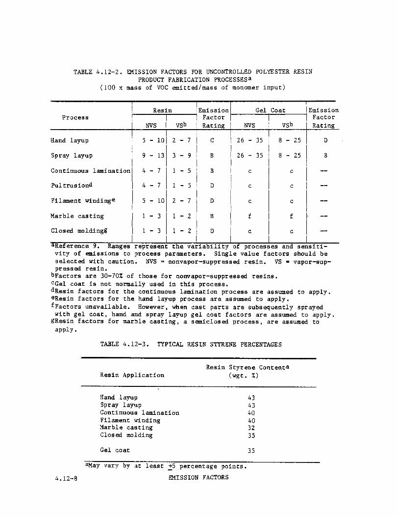
TABLE 4.12-2. EMISSION FACTORS FOR UNCONTROLLED POLYESTER RESIN PRODUCT FABRICATION PROCESSESa
(100 x mass of VOC emitted/mass of monomer input)
Process I Resin
I NVS I vsb
Hand layup I
5 -1012-7
Spray layup 9 - 13 3-9
Continuous lamination 4-7 l-5
Pultrusiond 4-7 1-5
Filament windinge 5- 10 2-7
Marble casting 1 -3 l-2
Closed moldingg 1 -3 1-2 I i
aReference 9. Ranges represent the variability of processes and sensiti- vity of emissions to process parameters. Single value factors should be selected with caution. NVS = nonvapor-suppressed resin. VS = vapor-sup- pressed resin.
I1
I1
I)
I)
I1
I)
Gel
NVS
26 - 35
26 - 35
emission Factor Rating
D
B
soat
vsb
8 - 25
8 - 25
C
C
C
f
C
-
--
--
--
-
emission Factor Rat:ing --
C
bFactors are 30-70X of those for nonvapor-suppressed resins. cGe1 coat is not normally used in this process. dResin factors for the continuous lamination process are assumed to apply. eResin factors for the hand layup process are assumed to apply. fFactors unavailable. However, when cast parts are subsequently sprayed with gel coat, hand and spray layup gel coat factors are assumed to apply.
gResin factors for marble casting, a semiclosed process, are assumed to wJ-y.
T’ =I=
TABLE 4.12-3. TYPICAL RESIN STYRENE PERCENTAGES
II 1
t
Resin Application Resin Styrene Contenta
(wgt. 4)
Hand layup 43 Spray layup 43 Continuous lamination 40 Filament winding 40 Marble casting 32 Closed molding 35
Gel coat 35
aMay vary by at least +5 percentage points.
4.12-8 EMISSION FACTORS

Emissions from use of gel coat would be calculated in the same manner. If the monomer content of the resins were unknown, a representative value of 43 percent could be selected from Table 4.12-3 for this process combina- tion. It should be noted that these emissions represent evaporation of styrene monomer only, and not of acetone OK other solvents used for clean- up*
In addition to process changes and materials substitution, add-on con- trol equipment can be used to reduce vapor emissions from styrene resins. However, control equipment is infrequently used at RP/C fabrication facili- ties, due to low exhaust VOC concentrations and the potential for contami- nation of adsorbent materials. Most plants use forced ventilation techni- ques to reduce worker exposure to styrene vapors, but vent the vapors directly to the atmosphere with no attempt at collection. At one contin- uous lamination facility where incineration was applied to vapors vented from the impregnation table, a 98.6 percent control efficiency was mea- sured.1 Carbon adsorption, absorption and condensation also have been considered for recovering styrene and other organic vapors, but these tech- niques have not been applied to any significant extent in this industry.
Emissions from.cleanup solvents can be controlled through good house- keeping and use practices, reclamation of spent solvent, and substitution with water based solvent substitutes.
References for Section 4.12
1.
2.
3.
4.
5.
6.
7.
M. B. Rogozen, Control Techniques for Qrganic Gas Emissions from Fiber- glass Impregnation and Fabrication Processes, ARB/R-82/165, California Air Resources Board, Sacramento, CA, (NTIS PB82-2511091, June 1982.
Modern Plastics Encyclopedia, 1986-1987,, 63 (lOA), October 1986. -
C. A. Brighton, G. Pritchard and G. A. Skinner, Styrene Polymers: Technology and Environmental Aspects, Applied Science Publishers, Ltd., London, 1979.
M. Elsherif, Staff Report, Proposed Rule 1162 - Polyester Resin Operations, South Coast Air Quality Management District, Rule Develop- ment Division, El Monte, CA, January 23, 1987.
M. S. Crandall, Extent of Exposure to Sltyrene in the Reinforced Plastic Boat Making Industry, Publication No. 8X-110, National Institute For Occupational Safety And Health, Cincinnati, OH, March 1982.
Written communication from R. C. Lepple, Aristech Chemical Corporation, Polyester Unit, Linden, NJ, to A. A. Mac-Queen, U.S. Environmental Pro- t'ection Agency, Research Triangle Park, NC, September 16, 1987.
L. Walewski and S. Stockton, "Low-Styrene-Emission Laminating Resins Prove It in the Workplace", Modern Plastics -, %(8);78-80, August 1985.
Evaporation Loss Sources 4.12-9

8. M. J. Duffy, "Styrene Emissions - How Effective Are Suppressed Polyester Resins?", Ashland Chemical Company, Dublin, OH, presented at 34th Annual Technical Conference, Reinforced Plastics/Composites Institute, The Society Of The Plastics Industry, 1979.
9. G. A. LaFlam, Emission Factor Documentation for AP-42 Section 4.12: Polyester Resin Plastics Product Fabrication, Pacific Environmental Services, Inc., Durham, NC, November 1987.
4.12-10 EMISSION FACTORS