emrc: efficient miss ratio approximation for multi-tier
TRANSCRIPT

This paper is included in the Proceedings of the 19th USENIX Conference on File and Storage Technologies.
February 23–25, 2021978-1-939133-20-5
Open access to the Proceedings of the 19th USENIX Conference on
File and Storage Technologies is sponsored by USENIX.
eMRC: Efficient Miss Ratio Approximation for Multi-Tier Caching
Zhang Liu, University of Colorado Boulder; Hee Won Lee, Samsung Electronics; Yu Xiang, AT&T Labs Research; Dirk Grunwald and Sangtae Ha,
University of Colorado Boulderhttps://www.usenix.org/conference/fast21/presentation/liu

eMRC: Efficient Miss Ratio Approximation for Multi-Tier Caching
Zhang LiuUniversity of Colorado Boulder
Hee Won Lee∗
Samsung ElectronicsYu Xiang
AT&T Labs Research
Dirk GrunwaldUniversity of Colorado Boulder
Sangtae HaUniversity of Colorado Boulder
Abstract
Many storage cache allocation methods use the miss ratio
curve (MRC) to improve cache efficiency. However, they havefocused only on single-tier cache architectures and requirethe whole MRC as input for cache management, while mod-ern datacenters embrace hierarchical caching architectures tomaximize resource utilization. Generating the MRC for multi-tier caches – we call it the miss ratio function – is far morechallenging due to different eviction policies and capacitiesin each cache tier. We introduce eMRC, a multi-dimensionalmiss ratio approximation technique, to enable efficient MRCgeneration for multi-tier caching. Our approach uses a novelmulti-dimensional performance cliff removal method and con-vex hull approximation technique to efficiently generate amulti-dimensional MRC without cliffs using a small numberof sampling points. To demonstrate the benefits of eMRC,we designed ORCA, a multi-tier cache management frame-work that orchestrates caches residing in different hierarchiesthrough eMRC and provides efficient multi-tier cache config-urations to cloud tenants with diverse service level objectives.We evaluate the performance of our eMRC approximationtechnique and ORCA with real-world datacenter traces.
1 Introduction
Caching is often provisioned on multiple tiers in cloud storagesystems. When client applications running in virtual machines(VMs) generate block IOs to remote storage media, the re-quests pass through a series of intermediate layers, such asuser-space libraries, hypervisors, and actual storage nodes.Each layer presents a caching opportunity, and thus mostcloud providers adopt multi-tier caching architectures to max-imize the utilization of scattered resources in the system [11].
Multi-tier caching necessitates an effective, low overheadcache management scheme as arbitrary cache configurations
∗Hee Won Lee conducted this project when he was at AT&T Labs Re-search.
for multiple tiers may not benefit tenants due to their side ef-fects such as double caching effects [27]. Configuring cachesfor tenants with diverse service level objectives (SLOs) re-quires efficient and accurate cache performance analysis foreach tier of the cache.
It is well known that effective cache management requiresa good understanding of IO workload characteristics. Withoutunderstanding the workload, systems usually rely on trial-and-error tuning methods that can be very inefficient. Themiss ratio curve (MRC) is a useful tool to capture workloadcharacteristics and tune system behavior. The MRC representsthe relationship between cache size and the correspondingcache miss ratio. Assuming workloads are relatively stableover time, the MRC derived from observed IO traces is knownto work effectively for single-tier caches [13].
The general workflow of utilizing miss ratio informationfor cache management is as follows: 1) the IO streams oftenants are analyzed, and a miss ratio function is generated torepresent the miss ratio for any given cache configurations foreach tenant; 2) based on tenants’ SLOs, a cache managementframework allocates the optimal cache size for each tenant. Inthis workflow, the performance primarily depends upon howquickly it estimates the miss ratio of a particular sized cachefor each tenant, given that the cache management frameworkneeds to handle multiple tenants, each with a different IOpattern in a datacenter.
Evaluating the miss ratios for all possible cache sizes isa very time-consuming task. SHARDS [25] and MiniatureSimulation [24] allow rapid MRC construction with reducedoverhead, and other efficient techniques have also been pro-posed [7, 10, 26].
These previous techniques are either specific to single-tiercaches or are inefficient for multi-tier caches. As shown inFigure 1, there are performance cliffs on the miss ratio surfacewhere miss ratios change dramatically with small changes incache size. The miss ratio surface is a multi-dimensional func-tion representing the relationship between cache size in eachtier of the cache hierarchy and the corresponding cache missratios. While evaluating cache configurations using multi-tier
USENIX Association 19th USENIX Conference on File and Storage Technologies 293

Figure 1: Miss ratio surface of MSR web_2 trace.
cache simulators such as PyMimircache [8, 30] is possible,and MRC cliff removal techniques [4, 6] are available forsingle-tier caching, to the best of our knowledge, there areno known algorithms that can remove performance cliffs inmiss ratio functions for multi-tier caches, or that can generatecontinuous miss ratio functions efficiently.
In this paper, we present our eMRC approach to achiev-ing the efficient, rapid generation of multi-dimensional missratio functions for multi-tier caching. eMRC is enabled byour convex hull algorithm and cache partitioning algorithm.The convex hull algorithm efficiently divides the whole multi-dimensional space into multiple regions without full knowl-edge of the multi-dimensional MRC. This convex hull al-gorithm only requires a small number of sampling pointsthat significantly reduces the computation time. The cachepartitioning algorithm then removes performance cliffs formulti-tier caching within any region bounded by data pointswith known miss ratio values; the resulting miss ratio func-tion is always equal to or better than the original miss ratiofunction without eMRC’s cache partitioning.
We also developed the ORCA cache orchestration frame-work for multi-tenant, multi-tier caching that leverages eMRC.We evaluate both eMRC and ORCA using real-world IOtraces released by Microsoft [1].
Our key contributions can be summarized as follows:
• We are the first to provide an algorithm, eMRC, thatremoves performance cliffs in multi-dimensional missratio functions for multi-tier caching.
• For eMRC, we develop a technique called Convex Hull
Approximation. In terms of the number of samplingpoints required, it speeds up MRC generation by 14times for two-tier caching and 4,527 times for four-tiercaching.
• ORCA uses eMRC to efficiently provide effective cacheconfigurations for tenants with diverse SLOs by selectingoptimal cache sizes and replacement policies.
• We evaluate our eMRC approximation method with realdatacenter traces and validate that ORCA provides ef-fective multi-tier cache configurations and boosts theperformance for various types of mixed workloads.
2 Background
In this section, we will review three concepts upon which oureMRC approximation is built.
2.1 Sampling and Statistical Similarity
Statistical similarity means a smaller sampled IO trace can beused to estimate the miss ratio of the original IO trace. Kessleret al. [12] defined the “10% sampling goal” for statistical
similarity: “A method meets the 10% sampling goal if, atleast 90% of the time, it estimates the trace’s true misses perinstruction with ≤ 10% relative error using ≤ 10% of thetrace”, and showed that constant-bits sampling satisfies sucha goal. Constant-bits sampling means selecting the IO entriesthat have the same value in some address bits.
Spatial sampling is a recently proposed technique to sampleIO traces with statistical similarity. It means taking the hashvalues of IO addresses A and then using modulus P and athreshold T on the hash value to determine what fraction ofIO operations to sample, hash(A)mod P < T . The resultingsampling rate is R = T/P.
Statistical similarity has been used in various MRC basedstudies, e.g., accelerating trace-driven simulations [24, 25]and altering cache behaviors by using shadow partitions [4].
2.2 Talus Cache Partitioning
Talus [4] is a recently proposed cache partitioning algo-rithm that can remove MRC performance cliffs for single-tiercaching. Talus utilizes statistical similarity of spatial sam-pled IO streams. Assuming the original miss ratio is m(x) forcache size x, passing a fraction1 ρ of an original IO streaminto a proportionally smaller cache partition of size x′ = ρx
will result in a statistically similar miss ratio:
m′(x′) = m(x′
ρ), where 0 ≤ ρ ≤ 1 (1)
The Talus algorithm divides a single cache into two par-titions so that the cache has a miss ratio that interpolatesbetween two points on the MRC of an original unpartitionedcache. To demonstrate the Talus algorithm, we use an MRCexample shown in Figure 2. A performance cliff exists be-tween cache sizes α and β, which are two convex hull points.If their cache miss ratios are m(α) and m(β), respectively,Talus partitioning technique can provide cache miss ratio m(x)whose value is between m(α) and m(β). The small-dottedMRC is the miss ratio after applying the Talus algorithm. TheTalus MRC curve is convex and lower than the MRC of theunpartitioned cache.
Now let us assume we want to configure cache partitions sothat the overall miss ratio is lowered from 66% to 53% with acache size of x= 0.99 GB that falls between α= 0.23 GB and
1The fraction means the sampling rate of spatial sampling.
294 19th USENIX Conference on File and Storage Technologies USENIX Association

Figure 2: Talus miss ratio cliff removal.
β = 1.60 GB. We can determine the miss ratio using the Talus
equation: mtalus(x) =β−xβ−α m(α)+ x−α
β−α m(β). Hence, for the
example of Figure 2, we can obtain:
mtalus(0.99) =1.60−0.99
1.60−0.23m(0.23)+
0.99−0.23
1.60−0.23m(1.60)
= 0.45×0.76+0.55×0.35
= 0.53.
To achieve this miss ratio, Talus method allocates two cachepartitions of size x1 and x2 such that x = x1 +x2. A fraction ρof the IOs will pass through the first cache partition of size
x1 = ρα where ρ = β−xβ−α , and the remaining fraction (1−ρ)
of the IOs will pass through the second cache partition of sizex2 = x− x1.
The resulting miss ratio for the first partition is m1(x1),which equals m(x1/ρ) by Equation 1. And the miss ratio forthe second partition, m2(x2), equals m( x−x1
1−ρ ).The resulting Talus miss ratio is:
mtalus(x) = ρm1(x1)+(1−ρ)m2(x2)
= ρm(x1
ρ)+(1−ρ)m(
x− x1
1−ρ)
=β− x
β−αm(α)+
x−α
β−αm(β)
In sum, we want to have the Talus cache behave like a mixof cache sizes α and β. The sample point x = 0.99 GB results
in ρ= β−xβ−α = (1.60−0.99)/(1.60−0.23) = 0.45. Thus, 45%
of the IOs will use a cache partition of x1 = ρα = 0.45×0.23 = 0.10 GB and they will have a miss ratio of m(x1/ρ) =m(α) = 0.76. The remaining 55% of the references will usea cache size of x− x1 = 0.99−0.10 = 0.89 GB with a missratio of m( x−x1
1−ρ ) = m(β) = 0.35. Across all the IOs, the missratio will be 0.45×0.76+0.55×0.35 = 0.53.
As this process is repeated for different points x between αand β, the resulting miss ratio curve will be a linear interpola-tion between the miss ratios at α and β.
2.3 Rapid MRC Generation
Existing research has mainly focused on using a subset of theoriginal trace to accelerate MRC generation. Some of them
focused on stack-based eviction policies, while others canapply to all eviction policies.
Stack-based cache eviction policies have the inclusion prop-
erty, meaning that for the same input IO, the cache of a largersize always contains all cached items in the cache of a smallersize. Simple cache eviction policies such as LRU and LFU arestack-based policies, but more complex eviction policies suchas ARC [17] or MQ [32] are not stack-based. SHARDS [25]is based on the stack distance algorithm of Mattson et al. [16],which generates the MRC with a single pass of the work-load trace. With the help of spatial downsampling, SHARDScan significantly reduce the computation time and memoryfootprint for long traces while generating relatively accurateMRCs.
Miniature-Simulation [24] is another recent advance inMRC generation for both stack and non-stack based evictionpolicies. It shows that heavy spatial downsampling can beused to generate a relatively accurate MRC by running aseparate scaled-down simulation for each cache size.
3 eMRC: Miss Ratio Approximation forMulti-Tier Caching
We will begin with an illustrative example to intuitively showhow eMRC works. After that, we will demonstrate that spa-tial sampling also works for more than one cache tier inSection 3.2. We will show how eMRC can remove multi-dimensional performance cliffs in a cliff region bounded bydata points with known miss ratios in Section 3.3. We explainhow to partition the whole multi-dimensional MRC into mul-tiple regions efficiently to apply eMRC for the entire space inSection 3.4. To simplify explanation, we first address two-tiercaching and then generalize our algorithm for three or moretier caching in Section 3.5.
3.1 Illustrative Example for eMRC
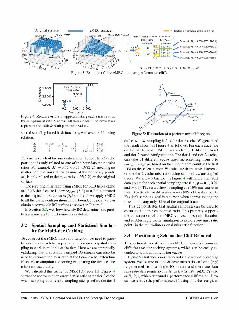
In single-tier caching, Talus achieves a convex MRC by par-titioning the cache into two partitions and letting the missratio of each partition be related to one of the boundary pointmiss ratios. In two-tier caching, as the example in Figure 3illustrates, there are four boundary points. eMRC partitionedthe last tier cache (2nd tier) into four partitions, with eachpartition related to one of the boundary point miss ratios.
In the particular example in Figure 3, there is a cliff regionin the MRC of a workload using two-tier caching. The fourboundary point miss ratios are: M(2,2) = 0.9, M(2,6) = 0.5,M(6,2) = 0.5 and M(6,6) = 0.5. If we use the two tiers ofcaches without partitioning, the miss ratio for 3GB of tier-1cache and 3GB of tier-2 cache is M(3,3) = 0.9.
eMRC ensures that if we partition the tier-1 cache intotwo partitions of [1.5GB, 1.5GB] and the tier-2 cache intofour partitions of [1.125GB, 1.125GB, 0.375GB, 0.375GB],and then divide the IOs into the different partitions using
USENIX Association 19th USENIX Conference on File and Storage Technologies 295
1.5 GB
0.375 GB1.5 GB
1.125 GB1.125 GB
0.375 GB
0.75
0.25
Tier-1 cachepartitions
Tier-2 cachepartitions
Miss ratio !! = 0.75×0.75×!(2,2)Miss ratio !" = 0.75×0.25×!(2,6)Miss ratio !# = 0.25×0.75×!(6,2)
Miss ratio !$ = 0.25×0.25×!(6,6)
0.75
0.250.75
0.25
IOs
eMRC Config
!!"#$ 3,3 = !1+!2+!3+!4 = 0.725
Original surface eMRC surface IO fractioning based on spatial sampling
M(2,2)=0.9
M(6,2)=0.5M(6,6)=0.5
M(2,6)=0.5
M(3,3) = 0.9 MeMRC(2,2)=0.9
MeMRC(6,2)=0.5 MeMRC (6,6)=0.5
MeMRC (2,6)=0.5
MeMRC (3,3) = 0.725
Figure 3: Example of how eMRC removes performance cliffs.
Figure 4: Relative errors in approximating cache miss ratiosby sampling at rate ρ across all workloads. The error barsrepresent the 10th & 90th percentile values.
spatial sampling based hash functions, we have the followingrelation:
[
M1M2M3M4
]
=
[
0.75×0.75 0 0 00 0.75×0.25 0 00 0 0.25×0.75 00 0 0 0.25×0.25
][
M(2,2)M(2,6)M(6,2)M(6,6)
]
This means each of the miss ratios after the four tier-2 cachepartitions is only related to one of the boundary point missratios. For example, M1 = 0.75×0.75×M(2,2), meaning nomatter how the miss ratios change at the boundary points,M1 is only related to the miss ratio at M(2,2) on the originalsurface.
The resulting miss ratio using eMRC for 3GB tier-1 cacheand 3GB tier-2 cache is now MeMRC(3,3) = 0.725 comparedto the original miss ratio at M(3,3) = 0.9. If we apply eMRCto all the cache configurations in the bounded region, we canobtain a convex eMRC surface as shown in Figure 3.
In Section 3.3, we show how eMRC determines the parti-tion parameters for cliff removals in detail.
3.2 Spatial Sampling and Statistical Similar-ity for Multi-tier Caching
To construct the eMRC miss ratio function, we need to parti-tion caches in each tier repeatedly; this requires spatial sam-pling to work in multiple cache tiers. Here we are empiricallyvalidating that a spatially sampled IO stream can also beused to estimate the miss ratio at the tier-2 cache, extendingKessler’s assumption concerning calculating the tier-1 cachemiss ratio accurately.
We validated this using the MSR IO traces [1]. Figure 4shows the approximation error in miss ratio at the tier-2 cachewhen sampling at different sampling rates ρ before the tier-1
Y1
m(X1, Y1)
Tier-1 Cache Size
Tier-2 Cach
e Size
X1
m(X2, Y1)
Y2
Miss
Rat
io
m(X1, 0)
m(X2, 0)
m(X1, Y2)
m(X2, Y2)
X2
Figure 5: Illustration of a performance cliff region.
cache, with no sampling before the tier-2 cache. We generatedthe result shown in Figure 4 as follows. For each trace, weevaluated the first 10M entries with 2,601 different tier-1and tier-2 cache configurations. The tier-1 and tier-2 cachescan take 51 different cache sizes incrementing from 0 tomax_cache_size, based on the unique item count in the first10M entries of each trace. We calculate the relative differenceon the tier-2 cache miss ratio using sampled vs. unsampledtraces. We show a bar plot in Figure 4 with more than 70Kdata points for each spatial sampling rate (i.e., ρ = 0.1, 0.01,and 0.001). The result shows sampling at a 10% rate causes atmost 0.62% relative difference across 90% of the data points.Kessler’s sampling goal is met even when approximating themiss ratio using only 0.1% of the original trace.
This demonstrates that spatial sampling can be used toestimate the tier-2 cache miss ratio. This property supportsthe construction of the eMRC convex miss ratio functionand enables rapid cache simulation to explore key miss ratiopoints in the multi-dimensional miss ratio function.
3.3 Partitioning Scheme for Cliff Removal
This section demonstrates how eMRC removes performancecliffs for two-tier caching systems, which can be easily ex-tended to work with multi-tier caches.
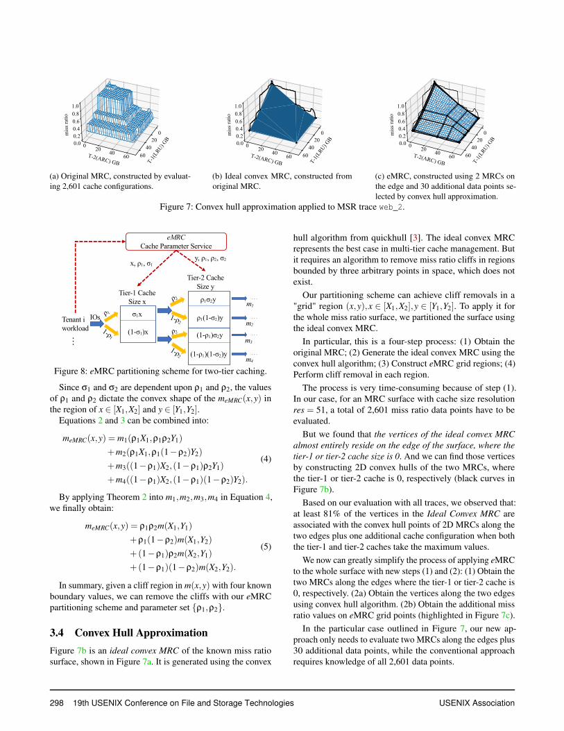
Figure 5 illustrates a miss ratio surface in a two-tier cachingsystem. We assume that the discrete miss ratio surface m(x,y)is generated from a single IO stream and there are fourmiss ratio data points, i.e., m(X1,Y1), m(X1,Y2), m(X2,Y1) andm(X2,Y2), which surround a performance cliff region. Howcan we remove the performance cliff using only the four given
296 19th USENIX Conference on File and Storage Technologies USENIX Association

Size xMiss ratio m1(x)
Size yMiss ratio m2(y)
Scenario 1No sampling
Scenario 2Sampling only before
Tier-1 cache
Scenario 3Sampling before bothTier-1 & Tier-2 caches
Size x’Miss ratio m1’(x’)
Size y’Miss ratio m2’(y’)
Size x’Miss ratio m1’(x’)
Size y’’Miss ratio m2’’ (y’’)
fraction ρ1
fraction ρ1
fraction ρ2
Miss Ratiom(x,y) = m1(x) m2(y)
Fractional Miss Ratiom’(x’,y’) = ρ1m1
’(x’) m2’(y’)Fractional Miss Ratio
m’’(x’,y’’) = ρ1m1’(x’) ρ2m2’’(y’’)
Missed IOsOUT(x,0)
Missed IOsOUT(x, y)
Missed IOsOUT ’(x’, 0)
Missed IOsOUT ’(x’, y’)
Missed IOsOUT ’(x’, 0)
Missed IOsOUT ’’ (x’, y’’)
Tier-1cache
Tier-2cache
Input IOsIN
Input IOsIN
Input IOsIN
Figure 6: IO sampling scenarios in two-tier cache system.
data points? The Talus algorithm only works for a single-tiercache because it needs two data points using the same inputIO stream. For example, in Figure 5, Talus cannot apply be-tween m(X1,Y1) and m(X2,Y1) because these two data pointsuse different input IO streams; one is the missed IOs whenthe tier-1 cache size is X1, and the other is when the tier-1cache size is X2.
The eMRC algorithm removes performance cliffs for two(or more) tier cache systems using the partitioning schemeoutlined in Figure 8.
We present our assumption and theorems that lead to theconstruction of a miss ratio surface meMRC(x,y) without per-formance cliffs. Figure 6 shows three scenarios that cover allpossible IO sampling cases in two-tier cache systems. Sce-narios 1 and 2 are used in the proof of Theorem 1. All threescenarios are used in the proof of Theorem 2.
• Scenario 1: No sampling. Let m1(x) and m2(y) denotethe cache miss ratios observed at the tier-1 and tier-2caches, respectively. OUT (x,0) is the missed IO streamafter the tier-1 cache, and OUT (x,y) is the one after thetier-2 cache. Then the miss ratio after the tier-1 cachem(x,0) equals m1(x), and the miss ratio after the tier-2cache m(x,y) equals m1(x)m2(y).
• Scenario 2: Sampling only before the tier-1 cache.When a fraction ρ1 of an IO stream is processed by twocache tiers, m′
1(x′) and m′
2(y′) denote the cache miss ra-
tios observed at the tier-1 and tier-2 caches, respectively.The miss ratio after the tier-1 cache m′(x′,0) will becomeρ1m′
1(x′) due to a fraction ρ1 of an input IO stream. Then
the fractional miss ratio is m′(x′,y′) = ρ1m′1(x
′)m′2(y
′).The fractional miss ratio is the miss ratio when a fractionof an IO stream is used.
• Scenario 3: Sampling before both tier-1 & tier-2caches. We sample the missed IO stream after the tier-1cache of size x′ (which is denoted by OUT ′(x′,0)) againwith fraction ρ2, and feed that into another tier-2 cache ofsize y′′. Then the fractional miss ratio m′′(x′,y′′) equalsρ1m′
1(x′)ρ2m′′
2(y′′).
With these three scenarios described, we introduce ourassumptions and theorems.
Assumption 1 If x′ = ρ1x and y′ = ρ1y, then the miss ratio
at the tier-2 cache m′2(y
′) and m2(y) are statistically similar.
This was shown empirically in §3.2. With this assumptionwe can now find the relationship between the fractional missratios m′(x′,y′), m′′(x′,y′′) in Scenarios 2 & 3 and the missratio m(x,y) in Scenario 1 for a two-tier cache system.
Theorem 1 For an input IO stream that is processed by two
tiers of caches with the resulting miss ratio surface m(x,y), a
fraction ρ1 of spatial sampled IO stream will have a fractional
miss ratio surface:
m′(x′,y′) = ρ1m(x′
ρ1,
y′
ρ1)
Proof: In a two-tier caching setup, when a fraction ρ1 ofan input IO stream passes through the tier-1 cache of sizex′ and then the tier-2 cache of size y′, the fractional missratio is m′(x′,y′) = ρ1m′
1(x′)m′
2(y′). From the Talus theorem,
we find m′1(x
′) = m1(x′/ρ1). Under Assumption 1, m′2(y
′) =m2(y′/ρ1). Putting them all together, we obtain:
m′(x′,y′) = ρ1m1(x′
ρ1)m2(
y′
ρ1) = ρ1m(
x′
ρ1,
y′
ρ1).
Theorem 2 For a given IO stream that is processed by two
tiers of the caches with resulting miss ratio surface m(x,y),downsampling with fraction ρ1 before the tier-1 cache of size
x′ and again downsampling with fraction ρ2 before the tier-2
cache of size y′′ results in new fractional miss ratio surface:
m′′(x′,y′′) = ρ1ρ2m(x′
ρ1,
y′′
ρ1ρ2)
Proof: From the Talus theorem, we find m′′2(y
′′) = m′2(y
′′/ρ2).
Hence, m′′(x′,y′′) = ρ1m′1(x
′)ρ2m′2(
y′′
ρ2). As m′(x′,y′) =
ρ1m′1(x
′)m′2(y
′), m′′(x′,y′′) = m′(x′, y′′
ρ2)ρ2. Applying Theo-
rem 1, we obtain:
m′′(x′,y′′) = ρ1ρ2m(x′
ρ1,
y′′
ρ1ρ2).
We now use Theorem 2 to remove cliffs in the miss ratiosurface. Let m(x,y) denote a region of the miss ratio sur-face of a two-tier caching system without any partitioning, forx ∈ [X1,X2],y ∈ [Y1,Y2], where m(X1,Y1),m(X1,Y2),m(X2,Y1)and m(X2,Y2) are known values. The meMRC(x,y) can be im-plemented by partitioning both cache tiers.
Figure 8 illustrates the partitioning scheme. The final missratio consists of four different fractional miss ratios after thetier-2 cache. Hence, meMRC(x,y) is the summation of all thefour miss ratios:
meMRC(x,y) = m1(σ1x,ρ1σ2y)
+m2(σ1x,ρ1(1−σ2)y)
+m3((1−σ1)x,(1−ρ1)σ2y)
+m4((1−σ1)x,(1−ρ1)(1−σ2)y).
(2)
where
ρ1 =X2−x
X2−X1,σ1 = ρ1
X1x ,ρ2 =
Y2−yY2−Y1
,σ2 = ρ2Y1y . (3)
USENIX Association 19th USENIX Conference on File and Storage Technologies 297
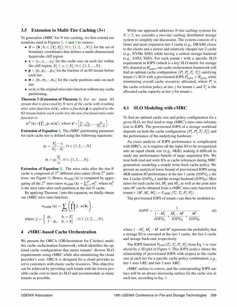
(a) Original MRC, constructed by evaluat-
ing 2,601 cache configurations.
(b) Ideal convex MRC, constructed from
original MRC.
(c) eMRC, constructed using 2 MRCs on
the edge and 30 additional data points se-
lected by convex hull approximation.
Figure 7: Convex hull approximation applied to MSR trace web_2.
Tenant iworkload
σ1xIOs
Tier-1 CacheSize x ρ1σ2y
Tier-2 CacheSize y
ρ1
1-ρ1(1-σ1)x
ρ2
1-ρ2
ρ2
1-ρ2
ρ1(1-σ2)y
(1-ρ1)σ2y
(1-ρ1)(1-σ2)y
. . .
. . .
. . .
. . .
. . .
eMRCCache Parameter Service
x, ρ1, σ1y, ρ1, ρ2, σ2
m1
m2
m3
m4Figure 8: eMRC partitioning scheme for two-tier caching.
Since σ1 and σ2 are dependent upon ρ1 and ρ2, the valuesof ρ1 and ρ2 dictate the convex shape of the meMRC(x,y) inthe region of x ∈ [X1,X2] and y ∈ [Y1,Y2].
Equations 2 and 3 can be combined into:
meMRC(x,y) = m1(ρ1X1,ρ1ρ2Y1)
+m2(ρ1X1,ρ1(1−ρ2)Y2)
+m3((1−ρ1)X2,(1−ρ1)ρ2Y1)
+m4((1−ρ1)X2,(1−ρ1)(1−ρ2)Y2).
(4)
By applying Theorem 2 into m1,m2,m3,m4 in Equation 4,we finally obtain:
meMRC(x,y) = ρ1ρ2m(X1,Y1)
+ρ1(1−ρ2)m(X1,Y2)
+(1−ρ1)ρ2m(X2,Y1)
+(1−ρ1)(1−ρ2)m(X2,Y2).
(5)
In summary, given a cliff region in m(x,y) with four knownboundary values, we can remove the cliffs with our eMRCpartitioning scheme and parameter set {ρ1,ρ2}.
3.4 Convex Hull Approximation
Figure 7b is an ideal convex MRC of the known miss ratiosurface, shown in Figure 7a. It is generated using the convex
hull algorithm from quickhull [3]. The ideal convex MRCrepresents the best case in multi-tier cache management. Butit requires an algorithm to remove miss ratio cliffs in regionsbounded by three arbitrary points in space, which does notexist.
Our partitioning scheme can achieve cliff removals in a"grid" region (x,y),x ∈ [X1,X2],y ∈ [Y1,Y2]. To apply it forthe whole miss ratio surface, we partitioned the surface usingthe ideal convex MRC.
In particular, this is a four-step process: (1) Obtain theoriginal MRC; (2) Generate the ideal convex MRC using theconvex hull algorithm; (3) Construct eMRC grid regions; (4)Perform cliff removal in each region.
The process is very time-consuming because of step (1).In our case, for an MRC surface with cache size resolutionres = 51, a total of 2,601 miss ratio data points have to beevaluated.
But we found that the vertices of the ideal convex MRC
almost entirely reside on the edge of the surface, where the
tier-1 or tier-2 cache size is 0. And we can find those verticesby constructing 2D convex hulls of the two MRCs, wherethe tier-1 or tier-2 cache is 0, respectively (black curves inFigure 7b).
Based on our evaluation with all traces, we observed that:at least 81% of the vertices in the Ideal Convex MRC areassociated with the convex hull points of 2D MRCs along thetwo edges plus one additional cache configuration when boththe tier-1 and tier-2 caches take the maximum values.
We now can greatly simplify the process of applying eMRCto the whole surface with new steps (1) and (2): (1) Obtain thetwo MRCs along the edges where the tier-1 or tier-2 cache is0, respectively. (2a) Obtain the vertices along the two edgesusing convex hull algorithm. (2b) Obtain the additional missratio values on eMRC grid points (highlighted in Figure 7c).
In the particular case outlined in Figure 7, our new ap-proach only needs to evaluate two MRCs along the edges plus30 additional data points, while the conventional approachrequires knowledge of all 2,601 data points.
298 19th USENIX Conference on File and Storage Technologies USENIX Association
3.5 Extension to Multi-Tier Caching (3+)
To generalize eMRC for N-tier caching, we first extend ournotations used in Figures 5, 6 and 8 to vectors:
• B = {b | bi ∈ {Xi1,X
i2},∀i ∈ {1,2, ...,N}} for the set of
boundary coordinates that defines a multi-dimensionalhypercube cliff region.
• x = [x1,x2, ...xN ] for the cache size on each tier withinthe cliff region, Xi
1 ≤ xi ≤ Xi2,∀i ∈ {1,2, ...,N}.
• ρρρ = [ρ1,ρ2, ...ρN ] for the fraction of an IO stream beforeeach tier.
• σσσ = [σ1,σ2, ...σN ] for the cache partition ratio on eachtier.
• m(x) is the original miss ratio function without any cachepartitioning.
Theorem 3 (Extension of Theorem 2) For an input IO
stream that is processed by N tiers of the cache with resulting
miss ratio function m(x), when a fraction ρρρ is applied to the
IO stream before each cache tier, the new fractional miss ratio
function is:
mN(x)=∏Ni=1ρi·m(x′), where x′=
[
x1ρ1, x2
ρ1ρ2,..., xN
∏Ni=1ρi
]
.
Extension of Equation 3. The eMRC partitioning parameterfor each cache tier is defined using the following equations:
ρi =Xi
2 − xi
Xi2 −Xi
1
,∀i ∈ {1,2, ...,N}
σi = ρiX i
1
xi,∀i ∈ {1,2, ...,N}.
Extension of Equation 5. The miss ratio after the tier-Ncache is composed of 2N different miss ratios (from 2N parti-tions; see Figure 8). Hence, meMRC(x) is computed by aggre-
gating all the 2N miss ratios meMRC(x) = ∑2N
i=1 mNi , where mN
i
is the miss ratio after each partition at the tier-N cache.By applying Theorem 3 into this equation, we finally obtain
our eMRC miss ratio function:
meMRC(x) = ∑b∈B
(
N
∏i=1
fi ·m(b)
)
,
where fi =
{
ρi, bi = Xi1
1−ρi, bi = Xi2
,∀i ∈ {1,2, ...,N}.
4 eMRC-based Cache Orchestration
We present the ORCA (ORchestration for CAches) multi-tier cache orchestration framework, which identifies the op-timal cache configuration that meets tenants’ diverse SLOrequirements using eMRC while also minimizing the cloudprovider’s cost. ORCA is designed for a cloud provider toserve customers with elastic cache resources. This objectivecan be achieved by providing each tenant with the lowest pos-sible cache cost to meet its SLO and accommodate as manytenants as possible.
While our approach addresses N-tier caching systems forN ≥ 2, we consider a two-tier caching distributed storagesystem to simplify our discussion. The system consists of afaster and more expensive tier-1 cache (e.g., DRAM) closerto the clients and a slower and relatively cheaper tier-2 cache(e.g., NVMe SSD) while having a central storage backend(e.g., SATA SSD). For each tenant i with a specific SLOrequirement in IOPS (which is a key SLO metric for storageIO), denoted as Ri
IOPS, our cache orchestration framework willfind an optimal cache configuration {Pi
1,Pi2,T
i1 ,T
i2} satisfying
tenant i’s SLO with a provisioned IOPS PiIOPS ≥ Ri
IOPS whileminimizing overall cache resources allocated, where Pi
j is
the cache eviction policy at tier- j for tenant i, and T ij is the
allocated cache capacity at tier- j for tenant i.
4.1 SLO Modeling with eMRC
To find an optimal cache size and policy configuration for agiven SLO, we first need to map eMRC’s miss ratio informa-tion to IOPS. The provisioned IOPS of a storage workloaddepends on both the cache configuration {Pi
1,Pi2,T
i1 ,T
i2} and
the performance of the underlying hardware.
An exact analysis of IOPS performance is complicatedwith MRCs, as it requires all the input IO to be reorganizedinto an equal chunk size (e.g., 4KB), making it difficult tostudy any performance benefit of large sequential IOs. Wetreat both read and write IOs as cache references during MRCgeneration, modeling a simple write-back cache policy. Wepresent an analytical lower bound of provisioned IOPS using4KB random IO performance at the tier-1 cache (IOPST1
), thetier-2 cache (IOPST2
), and the storage backend (IOPSB). Missratios for each cache tier, Mi
1 and Mi2, as well as the joint miss
ratio Mi can be obtained from a eMRC miss ratio function fortenant i: (Mi,Mi
1,Mi2) = FeMRCi(T
i1 ,T
i2 ,P
i1,P
i2).
The provisioned IOPS of tenant i can then be modeled as:
IOPSi =1
1−Mi1
IOPST1
+Mi
1 −Mi
IOPST2
+Mi
IOPSB
(6)
where 1−Mi1, Mi
1 −Mi and Mi represents the probability thata storage IO is executed at the tier-1 cache, the tier-2 cacheand storage back-end, respectively.
The IOPS function FIOPS(T i1 ,T
i2 ,P
i1,P
i2) from Eq. 6 is visu-
alized by a 3D plot in Figure 9. This IOPS surface shows therelationship of provisioned IOPS with respect to the cachesize at each tier for a specific cache policy combination, e.g.,tier-1 uses LRU and tier-2 uses ARC.
eMRC surface is convex, and the corresponding IOPS sur-face will be an always increasing surface for the cache size ineach tier, according to Eq. 6.
USENIX Association 19th USENIX Conference on File and Storage Technologies 299

Figure 9: IOPS surface translated from eMRC surface forMSR proj_3 trace.
4.2 Cache Orchestration with eMRC
ORCA provides an optimal cache configuration {T i1, T i
2, Pi1,
Pi2} that minimizes the overall cost of cache resources while
meeting each tenant’s SLO requirements. The cost on cacheresource of tenant i with capacity configuration {T i
1, T i2} can
be denoted as Ci = C1 ×T i1 +C2 ×T i
2, where C1 and C2 arethe unit costs for the tier-1 and tier-2 caches, respectively.
For M tenants, the problem can be formulated as follows:
minimizeM
∑i=1
Ci (7a)
subject to Ci =C1T i1 +C2T i
2 (7b)
IOPSi = FIOPS(Ti
1 ,Ti
2 ,Pi1,P
i2) (7c)
IOPSi ≥ RiIOPS,∀i ∈ {1, ...,M} (7d)
var. {T i1 ,T
i2 ,P
i1,P
i2} (7e)
The unit cost of the tier-1 and tier-2 caches (C1 and C2)are adjustable by the cloud provider. By adjusting the ratioof C1/C2, the cloud provider will be able to shift utilizationbetween the tier-1 and tier-2 caches.
4.3 Two-Stage ORCA Optimization
The cache orchestration problem is challenging even witheMRC. We need to search through tons of configuration can-didates for each tenant’s optimal multi-tier cache configura-tion, with all the SLO and cache capacity constraints, whichwould incur a heavy computation overhead. Because an onlinecache orchestration system requires an efficient and yet accu-rate algorithm to adapt to large-scale, dynamic workloads, wepropose an efficient Two-stage ORCA optimization algorithm.The ORCA optimization splits the optimization over its ob-jective (minimizing cache resource cost) and its constraints(required IOPS and cache sizes), significantly reducing thesearch space for the optimization problem.
We propose Algorithm 1 to construct the set Bi, whichcontains cache configurations that are just enough to satisfyRi
IOPS +Di for tenant i, where RiIOPS is the requested IOPS
from tenant i and Di is an additional margin added to accountfor the prediction error caused by spatial downsampling andworkload dynamics. We define the tier-1 cache size x1, algo-rithm step m as a function of cache size resolution res and
Algorithm 1: ORCA-Space Search
Input: TMAX ,FIOPS,res,RiIOPS,D
i
tier-1 cache size x1[m] = mres−1 ·TMAX ,m ∈ range(res)
tier-2 cache size x2[n] =n
res−1 ·TMAX ,n ∈ range(res)
RiIOPS = Ri
IOPS +Di
for each cache policy combination (Pi1,P
i2) do
Do binary search to find m such that
FIOPS(x1[m−1],x2[0])< RiIOPS and
FIOPS(x1[m],x2[0])>= RiIOPS
Add (x1[m],x2[0],Pi1,P
i2,) to Bi
for n in [1, ..., res−1]) dom′ = m
use (x1[m′],x2[n]) as starting point to find m such
that
FIOPS(x1[m−1],x2[n])< RiIOPS and
FIOPS(x1[m],x2[n])>= RiIOPS
Add (x1[m],x2[n],Pi1,P
i2) to Bi
end
end
Output: Bi, a reduced set of cache configurations
TMAX2. We define x2 as the tier-2 cache size and the algo-
rithm step as n in a similar way. Then, for each cache policyconfiguration {Pi
1, Pi2}, we first find the first cache configura-
tion (via binary search) that satisfies the IOPS SLO when thetier-2 cache size is zero x2[0] = 0. Then we search among itsnearest neighbor points where x2[1] =
1res−1 ·TMAX to find the
next candidate cache configuration.
The algorithm will complete when the search reaches TMAX
for the tier-2 cache size; at this point, Bi will be constructedfor a given cache policy configuration. We do this for allcache policy configurations to construct a complete set of Bi
for each tenant i; such a set of Bi includes all cache config-urations that are just enough to satisfy tenant i’s SLO plusa margin. We then apply Algorithm 2 to perform optimiza-tion over cache configuration set Bi for each tenant i, whichwill provide the cache configuration with minimum cacheresource cost, defined in Eq. (7a) and Eq. (7b). Accordingto Eq. (7a), ∑M
i=1 Ci gets minimized when each Ci gets mini-mized; thus Algorithm 2 aims at minimizing the cost for eachtenant i over cache configurations that already meet the SLOrequirements from Algorithm 1.
5 Performance Evaluation
We evaluated our eMRC approximation technique and ORCAon a server with two Xeon Gold 6142 CPUs at 2.6GHz with384GB of memory, with a subset of Microsoft’s MSR IOtraces obtained from SNIA [1, 18]. We treat both read andwrite IOs as cache references during MRC generation, mod-eling a simple write-back cache policy. We break any largeIOs into 4KB blocks. For IOs smaller than 4KB, we treatthem as a full 4KB access. The traces we use all have more
2The unique IO entries in the trace.
300 19th USENIX Conference on File and Storage Technologies USENIX Association
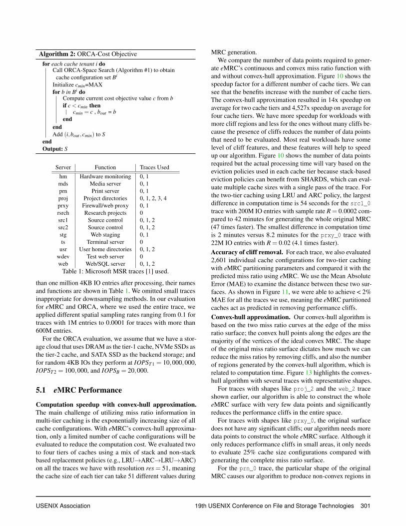
Algorithm 2: ORCA-Cost Objective
for each cache tenant i doCall ORCA-Space Search (Algorithm #1) to obtain
cache configuration set Bi
Initialize cmin=MAX
for b in Bi doCompute current cost objective value c from b
if c < cmin thencmin = c , bout = b
end
end
Add (i,bout ,cmin) to S
end
Output: S
Server Function Traces Used
hm Hardware monitoring 0, 1
mds Media server 0, 1
prn Print server 0, 1
proj Project directories 0, 1, 2, 3, 4
prxy Firewall/web proxy 0, 1
rsrch Research projects 0
src1 Source control 0, 1, 2
src2 Source control 0, 1, 2
stg Web staging 0, 1
ts Terminal server 0
usr User home directories 0, 1, 2
wdev Test web server 0
web Web/SQL server 0, 1, 2
Table 1: Microsoft MSR traces [1] used.
than one million 4KB IO entries after processing, their namesand functions are shown in Table 1. We omitted small tracesinappropriate for downsampling methods. In our evaluationfor eMRC and ORCA, where we used the entire trace, weapplied different spatial sampling rates ranging from 0.1 fortraces with 1M entries to 0.0001 for traces with more than600M entries.
For the ORCA evaluation, we assume that we have a stor-age cloud that uses DRAM as the tier-1 cache, NVMe SSDs asthe tier-2 cache, and SATA SSD as the backend storage; andfor random 4KB IOs they perform at IOPST 1 = 10,000,000,IOPST 2 = 100,000, and IOPSB = 20,000.
5.1 eMRC Performance
Computation speedup with convex-hull approximation.The main challenge of utilizing miss ratio information inmulti-tier caching is the exponentially increasing size of allcache configurations. With eMRC’s convex-hull approxima-tion, only a limited number of cache configurations will beevaluated to reduce the computation cost. We evaluated twoto four tiers of caches using a mix of stack and non-stackbased replacement policies (e.g., LRU→ARC→LRU→ARC)on all the traces we have with resolution res = 51, meaningthe cache size of each tier can take 51 different values during
MRC generation.We compare the number of data points required to gener-
ate eMRC’s continuous and convex miss ratio function withand without convex-hull approximation. Figure 10 shows thespeedup factor for a different number of cache tiers. We cansee that the benefits increase with the number of cache tiers.The convex-hull approximation resulted in 14x speedup onaverage for two cache tiers and 4,527x speedup on average forfour cache tiers. We have more speedup for workloads withmore cliff regions and less for the ones without many cliffs be-cause the presence of cliffs reduces the number of data pointsthat need to be evaluated. Most real workloads have somelevel of cliff features, and these features will help to speedup our algorithm. Figure 10 shows the number of data pointsrequired but the actual processing time will vary based on theeviction policies used in each cache tier because stack-basedeviction policies can benefit from SHARDS, which can eval-uate multiple cache sizes with a single pass of the trace. Forthe two-tier caching using LRU and ARC policy, the largestdifference in computation time is 54 seconds for the src1_0trace with 200M IO entries with sample rate R = 0.0002 com-pared to 42 minutes for generating the whole original MRC(47 times faster). The smallest difference in computation timeis 2 minutes versus 8.2 minutes for the prxy_0 trace with22M IO entries with R = 0.02 (4.1 times faster).
Accuracy of cliff removal. For each trace, we also evaluated2,601 individual cache configurations for two-tier cachingwith eMRC partitioning parameters and compared it with thepredicted miss ratio using eMRC. We use the Mean AbsoluteError (MAE) to examine the distance between these two sur-faces. As shown in Figure 11, we were able to achieve < 2%MAE for all the traces we use, meaning the eMRC partitionedcaches act as predicted in removing performance cliffs.
Convex-hull approximation. Our convex-hull algorithm isbased on the two miss ratio curves at the edge of the missratio surface; the convex hull points along the edges are themajority of the vertices of the ideal convex MRC. The shapeof the original miss ratio surface dictates how much we canreduce the miss ratios by removing cliffs, and also the numberof regions generated by the convex-hull algorithm, which isrelated to computation time. Figure 13 highlights the convex-hull algorithm with several traces with representative shapes.
For traces with shapes like proj_2 and the web_2 traceshown earlier, our algorithm is able to construct the wholeeMRC surface with very few data points and significantlyreduces the performance cliffs in the entire space.
For traces with shapes like prxy_0, the original surfacedoes not have any significant cliffs; our algorithm needs moredata points to construct the whole eMRC surface. Although itonly reduces performance cliffs in small areas, it only needsto evaluate 25% cache size configurations compared withgenerating the complete miss ratio surface.
For the prn_0 trace, the particular shape of the originalMRC causes our algorithm to produce non-convex regions in
USENIX Association 19th USENIX Conference on File and Storage Technologies 301
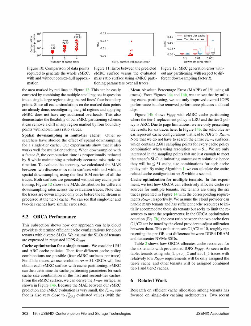
Figure 10: Comparison of data pointsrequired to generate the whole eMRC,with and without convex-hull approxi-mation.
Figure 11: Error between the predictedeMRC surface versus the evaluatedmiss ratio surface using eMRC parti-tioning parameters over all traces.
Figure 12: MRC generation error with-out any partitioning, with respect to dif-ferent down-sampling factor R.
the area marked by red lines in Figure 13. This can be easilycorrected by combining the multiple small regions in questioninto a single large region using the red lines’ four boundarypoints. Since all cache simulations on the marked data pointsare already done, reconfiguring the grid regions and applyingeMRC does not have any additional overheads. This alsodemonstrates the flexibility of our eMRC partitioning scheme;it can remove a cliff in any region marked by four boundarypoints with known miss ratio values.
Spatial downsampling in multi-tier cache. Other re-searchers have studied the effect of spatial downsamplingfor a single-tier cache. Our experiments show that it alsoworks well for multi-tier caching. When downsampled witha factor R, the computation time is proportionally reducedby R while maintaining a relatively accurate miss ratio es-timation. To evaluate the accuracy, we calculated the MAEbetween two discrete miss ratio surfaces with and withoutspatial downsampling using the first 10M entries of all thetraces. Both surfaces are generated without any cache parti-tioning. Figure 12 shows the MAE distribution for differentdownsampling rates across the evaluation traces. Note thatthe traces are downsampled only once before the IO stream isprocessed at the tier-1 cache. We can see that single-tier andtwo-tier caches have similar error rates.
5.2 ORCA Performance
This subsection shows how our approach can help cloudproviders determine efficient cache configurations for cloudtenants with diverse SLOs. We assume the SLOs of tenantsare expressed in requested IOPS RIOPS.
Cache optimization for a single tenant. We consider LRUand ARC cache policies. Then four different cache policycombinations are possible (four eMRC surfaces per trace).For all the traces, we use resolution res = 51. ORCA will firstobtain each eMRC surface with cache partitioning. eMRCcan then determine the cache partitioning parameters for eachcache size combination in the first and second-tier caches.From the eMRC surface, we can derive the FIOPS surface, asshown in Figure 14b. Because the MAE between our eMRCprediction and eMRC evaluation is very small, the FIOPS sur-face is also very close to F ′
IOPS evaluated values (with the
Mean Absolute Percentage Error (MAPE) of 1% using alltraces). From Figures 14a and 14b, we can see that by utiliz-ing cache partitioning, we not only improved overall IOPSperformance but also removed performance plateaus and localdips.
Figure 14b shows FIOPS with eMRC cache partitioningwhere the tier-1 replacement policy is LRU and the tier-2 pol-icy is ARC. Due to page limitations, we are only presentingthe results for six traces here. In Figure 14b, the solid blue ar-eas represent cache configurations that lead to IOPS > RIOPS.Note that we do not have to search the entire FIOPS surfaces,which contains 2,601 sampling points for every cache policycombination when using resolution res = 51. We are onlyinterested in the sampling points that are just enough to meetthe tenant’s SLO, eliminating unnecessary solutions; hencethey will be ≤ 51 cache size combinations for each cachepolicy pair. By using Algorithm 1, we can calculate the entirerelated cache configuration set B within a second.
Cache optimization for multiple tenants. In this experi-ment, we test how ORCA can effectively allocate cache re-sources for multiple tenants. Six tenants are using the sixtraces presented in Figure 14 with the corresponding require-ments RIOPS, respectively. We assume the cloud provider canhandle many tenants and has sufficient cache resources to ini-tially accommodate these six tenants but seeks to limit the re-sources to meet the requirements. In the ORCA optimizationequation (Eq. 7b), the cost ratio between the two cache tiersC1/C2 can be tuned by the cloud provider to adjust utilizationbetween them. This evaluation sets C1/C2 = 10, roughly rep-resenting the per-GB cost difference between DDR4 DRAMand datacenter NVMe SSDs.
Table 2 shows how ORCA allocates cache resources forthe six tenants with provisioned IOPS PIOPS. As seen in thetable, tenants using mds_1, proj_2 and src1_0 traces withrelatively low RIOPS requirements will be only assigned thetier-2 cache, and other tenants will be assigned combinedtier-1 and tier-2 caches.
6 Related Work
Research on efficient cache allocation among tenants hasfocused on single-tier caching architectures. Two recent
302 19th USENIX Conference on File and Storage Technologies USENIX Association
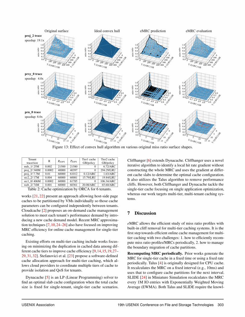
Figure 13: Effect of convex hull algorithm on various original miss ratio surface shapes.
Tenanttrace/size
R RIOPS PIOPSTier1 cacheGB/policy
Tier2 cacheGB/policy
mds_1/ 25M 0.002 21500 21580 0 6.72/ARC
proj_2/ 340M 0.0002 40000 40397 0 294.29/LRU
proj_3/ 7.7M 0.01 60000 61012 0.12/ARC 1.63/ARC
src2_2/ 17M 0.004 60000 60081 15.79/LRU 19.84/LRU
src1_0/ 406M 0.0002 60000 61785 0 106.34/ARC
web_2/ 74M 0.001 60000 60361 20.08/ARC 65.60/ARC
Table 2: Cache optimization by ORCA for 6 tenants.
works [21, 22] present an approach allowing host-side pagecaches to be partitioned by VMs individually so those cacheparameters can be configured independently between tenants.Cloudcache [2] proposes an on-demand cache managementsolution to meet each tenant’s performance demand by intro-ducing a new cache demand model. Recent MRC approxima-tion techniques [7,10,24–26] also have focused on improvingMRC efficiency for online cache management for single-tiercaching.
Existing efforts on multi-tier caching include works focus-ing on minimizing the duplication in cached data among dif-ferent cache tiers to improve cache efficiency [9,14,15,19,27–29, 31, 32]. Stefanovici et al. [23] propose a software-definedcache allocation approach for multi-tier caching, which al-lows cloud providers to coordinate multiple tiers of cache toprovide isolation and QoS for tenants.
Dynacache [5] is an LP (Linear Programming) solver tofind an optimal slab cache configuration when the total cachesize is fixed for single-tenant, single-tier cache scenarios.
Cliffhanger [6] extends Dynacache. Cliffhanger uses a noveliterative algorithm to identify a local hit rate gradient withoutconstructing the whole MRC and uses the gradient at differ-ent cache slabs to determine the optimal cache configuration.It also utilizes the Talus algorithm to remove performancecliffs. However, both Cliffhanger and Dynacache tackle thesingle-tier cache focusing on single application optimization,whereas our work targets multi-tier, multi-tenant caching sys-tems.
7 Discussion
eMRC allows the efficient study of miss ratio profiles withbuilt-in cliff removal for multi-tier caching systems. It is thefirst step towards efficient online cache management for multi-tier caching with two challenges: 1. how to efficiently recom-pute miss ratio profiles/MRCs periodically, 2. how to managethe boundary migration of cache partitions.
Recomputing MRC periodically. Prior works generate theMRC for single-tier cache in a fixed time or using a fixed rateperiodically. Talus [4] is originally designed for CPU cache.It recalculates the MRC on a fixed interval (e.g., 10ms) anduses that to configure cache partitions for the next interval.SLIDE [24] in Miniature Simulation recalculates the MRCevery 1M IO entries with Exponentially Weighted MovingAverage (EWMA). Both Talus and SLIDE require the knowl-
USENIX Association 19th USENIX Conference on File and Storage Technologies 303
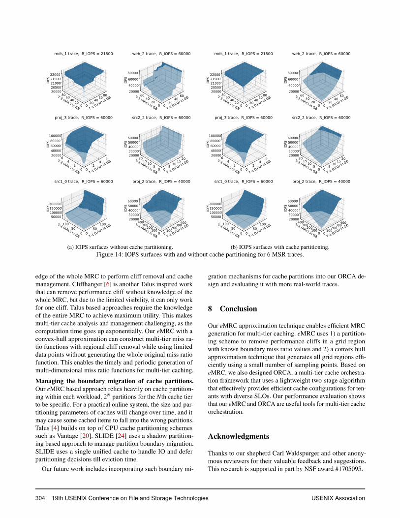
(a) IOPS surfaces without cache partitioning. (b) IOPS surfaces with cache partitioning.
Figure 14: IOPS surfaces with and without cache partitioning for 6 MSR traces.
edge of the whole MRC to perform cliff removal and cachemanagement. Cliffhanger [6] is another Talus inspired workthat can remove performance cliff without knowledge of thewhole MRC, but due to the limited visibility, it can only workfor one cliff. Talus based approaches require the knowledgeof the entire MRC to achieve maximum utility. This makesmulti-tier cache analysis and management challenging, as thecomputation time goes up exponentially. Our eMRC with aconvex-hull approximation can construct multi-tier miss ra-tio functions with regional cliff removal while using limiteddata points without generating the whole original miss ratiofunction. This enables the timely and periodic generation ofmulti-dimensional miss ratio functions for multi-tier caching.
Managing the boundary migration of cache partitions.Our eMRC based approach relies heavily on cache partition-ing within each workload, 2N partitions for the Nth cache tierto be specific. For a practical online system, the size and par-titioning parameters of caches will change over time, and itmay cause some cached items to fall into the wrong partitions.Talus [4] builds on top of CPU cache partitioning schemessuch as Vantage [20]. SLIDE [24] uses a shadow partition-ing based approach to manage partition boundary migration.SLIDE uses a single unified cache to handle IO and deferpartitioning decisions till eviction time.
Our future work includes incorporating such boundary mi-
gration mechanisms for cache partitions into our ORCA de-sign and evaluating it with more real-world traces.
8 Conclusion
Our eMRC approximation technique enables efficient MRCgeneration for multi-tier caching. eMRC uses 1) a partition-ing scheme to remove performance cliffs in a grid regionwith known boundary miss ratio values and 2) a convex hullapproximation technique that generates all grid regions effi-ciently using a small number of sampling points. Based oneMRC, we also designed ORCA, a multi-tier cache orchestra-tion framework that uses a lightweight two-stage algorithmthat effectively provides efficient cache configurations for ten-ants with diverse SLOs. Our performance evaluation showsthat our eMRC and ORCA are useful tools for multi-tier cacheorchestration.
Acknowledgments
Thanks to our shepherd Carl Waldspurger and other anony-mous reviewers for their valuable feedback and suggestions.This research is supported in part by NSF award #1705095.
304 19th USENIX Conference on File and Storage Technologies USENIX Association

References
[1] SNIA IOTTA repository. http://iotta.snia.org.
[2] Dulcardo Arteaga, Jorge Cabrera, Jing Xu, SwaminathanSundararaman, and Ming Zhao. Cloudcache: On-demand flash cache management for cloud computing.In 14th USENIX Conference on File and Storage Tech-
nologies (FAST 16), pages 355–369, Santa Clara, CA,2016. USENIX Association.
[3] C Bradford Barber, David P Dobkin, David P Dobkin,and Hannu Huhdanpaa. The quickhull algorithm for con-vex hulls. ACM Transactions on Mathematical Software
(TOMS), 22(4):469–483, 1996.
[4] Nathan Beckmann and Daniel Sanchez. Talus: A simpleway to remove cliffs in cache performance. In 2015
IEEE 21st International Symposium on High Perfor-
mance Computer Architecture (HPCA), pages 64–75.IEEE, 2015.
[5] Asaf Cidon, Assaf Eisenman, Mohammad Alizadeh, andSachin Katti. Dynacache: Dynamic cloud caching. In7th USENIX Workshop on Hot Topics in Cloud Comput-
ing (HotCloud 15), 2015.
[6] Asaf Cidon, Assaf Eisenman, Mohammad Alizadeh, andSachin Katti. Cliffhanger: Scaling performance cliffs inweb memory caches. In 13th USENIX Symposium on
Networked Systems Design and Implementation NSDI
16), pages 379–392, 2016.
[7] D. Eklov and E. Hagersten. Statstack: Efficient mod-eling of lru caches. In 2010 IEEE International Sym-
posium on Performance Analysis of Systems Software
(ISPASS), pages 55–65, March 2010.
[8] Tyler Estro, Pranav Bhandari, Avani Wildani, and ErezZadok. Desperately seeking... optimal multi-tier cacheconfigurations. In 12th USENIX Workshop on Hot Top-
ics in Storage and File Systems (HotStorage 20), 2020.
[9] Binny S. Gill. On multi-level exclusive caching: Offlineoptimality and why promotions are better than demo-tions. In 6th USENIX Conference on File and Storage
Technologies (FAST 08), San Jose, CA, 2008. USENIXAssociation.
[10] Xiameng Hu, Xiaolin Wang, Lan Zhou, Yingwei Luo,Chen Ding, and Zhenlin Wang. Kinetic modeling of dataeviction in cache. In 2016 USENIX Annual Technical
Conference (USENIX ATC 16), pages 351–364, Denver,CO, 2016. USENIX Association.
[11] Dejun Jiang, Yukun Che, Jin Xiong, and Xiaosong Ma.ucache: A utility-aware multilevel ssd cache manage-ment policy. In 2013 IEEE 10th International Con-
ference on High Performance Computing and Commu-
nications & 2013 IEEE International Conference on
Embedded and Ubiquitous Computing, pages 391–398.IEEE, 2013.
[12] Richard E. Kessler, Mark D Hill, and David A Wood.A comparison of trace-sampling techniques for multi-megabyte caches. IEEE Transactions on Computers,43(6):664–675, 1994.
[13] R. Koller, A. J. Mashtizadeh, and R. Rangaswami. Cen-taur: Host-side ssd caching for storage performancecontrol. In 2015 IEEE International Conference on
Autonomic Computing, pages 51–60, July 2015.
[14] Wenji Li, Gregory Jean-Baptise, Juan Riveros, GiriNarasimhan, Tony Zhang, and Ming Zhao. Cachededup:In-line deduplication for flash caching. In 14th USENIX
Conference on File and Storage Technologies (FAST
16), pages 301–314, Santa Clara, CA, 2016. USENIXAssociation.
[15] Xuhui Li, Ashraf Aboulnaga, Kenneth Salem, AamerSachedina, and Shaobo Gao. Second-tier cache man-agement using write hints. In Proceedings of the 4th
Conference on USENIX Conference on File and Storage
Technologies - Volume 4, FAST’05, pages 9–9, Berkeley,CA, USA, 2005. USENIX Association.
[16] R. L. Mattson, J. Gecsei, D. R. Slutz, and I. L. Traiger.Evaluation techniques for storage hierarchies. IBM Syst.
J., 9(2):78–117, June 1970.
[17] Nimrod Megiddo and Dharmendra S. Modha. Arc: Aself-tuning, low overhead replacement cache. In Pro-
ceedings of the 2Nd USENIX Conference on File and
Storage Technologies, FAST ’03, pages 115–130, Berke-ley, CA, USA, 2003. USENIX Association.
[18] Dushyanth Narayanan, Austin Donnelly, and AntonyRowstron. Write off-loading: Practical power manage-ment for enterprise storage. ACM Transactions on Stor-
age (TOS), 4(3):10, 2008.
[19] L. Ou, X. He, M. J. Kosa, and S. L. Scott. A unifiedmultiple-level cache for high performance storage sys-tems. In 13th IEEE International Symposium on Model-
ing, Analysis, and Simulation of Computer and Telecom-
munication Systems, pages 143–150, Sept 2005.
[20] Daniel Sanchez and Christos Kozyrakis. Vantage: scal-able and efficient fine-grain cache partitioning. In Pro-
ceedings of the 38th annual international symposium on
Computer architecture, pages 57–68, 2011.
USENIX Association 19th USENIX Conference on File and Storage Technologies 305

[21] P. Sharma, P. Kulkarni, and P. Shenoy. Per-vm pagecache partitioning for cloud computing platforms. In2016 8th International Conference on Communication
Systems and Networks (COMSNETS), pages 1–8, Jan2016.
[22] Prateek Sharma and Purushottam Kulkarni. Singleton:System-wide page deduplication in virtual environments.In Proceedings of the 21st International Symposium on
High-Performance Parallel and Distributed Computing,HPDC ’12, pages 15–26, New York, NY, USA, 2012.ACM.
[23] Ioan Stefanovici, Eno Thereska, Greg O’Shea, BiancaSchroeder, Hitesh Ballani, Thomas Karagiannis, AntonyRowstron, and Tom Talpey. Software-defined caching:Managing caches in multi-tenant data centers. In Pro-
ceedings of the Sixth ACM Symposium on Cloud Com-
puting, SoCC ’15, pages 174–181, New York, NY, USA,2015. ACM.
[24] Carl Waldspurger, Trausti Saemundsson, Irfan Ahmad,and Nohhyun Park. Cache modeling and optimizationusing miniature simulations. In 2017 USENIX Annual
Technical Conference (USENIX ATC 17), pages 487–498, Santa Clara, CA, 2017. USENIX Association.
[25] Carl A. Waldspurger, Nohhyun Park, Alexander Garth-waite, and Irfan Ahmad. Efficient MRC constructionwith SHARDS. In 13th USENIX Conference on File and
Storage Technologies (FAST 15), pages 95–110, SantaClara, CA, 2015. USENIX Association.
[26] Jake Wires, Stephen Ingram, Zachary Drudi, NicholasJ. A. Harvey, and Andrew Warfield. Characterizing stor-age workloads with counter stacks. In 11th USENIX
Symposium on Operating Systems Design and Imple-
mentation (OSDI 14), pages 335–349, Broomfield, CO,2014. USENIX Association.
[27] Theodore M. Wong and John Wilkes. My cache oryours? making storage more exclusive. In Proceed-
ings of the General Track of the Annual Conference on
USENIX Annual Technical Conference, ATC ’02, pages161–175, Berkeley, CA, USA, 2002. USENIX Associa-tion.
[28] C. Wu, X. He, Q. Cao, and C. Xie. Hint-k: An efficientmulti-level cache using k-step hints. In 2010 39th In-
ternational Conference on Parallel Processing, pages624–633, Sept 2010.
[29] Gala Yadgar, Michael Factor, and Assaf Schuster.Karma: Know-it-all replacement for a multilevel cache.In Proceedings of the 5th USENIX Conference on File
and Storage Technologies, FAST ’07, pages 25–25,Berkeley, CA, USA, 2007. USENIX Association.
[30] Juncheng Yang. Pymimircache. https://github.
com/1a1a11a/. Retrieved Dec. 2020.
[31] Yuanyuan Zhou, Zhifeng Chen, and Kai Li. Second-level buffer cache management. IEEE Trans. Parallel
Distrib. Syst., 15(6):505–519, June 2004.
[32] Yuanyuan Zhou, James Philbin, and Kai Li. The multi-queue replacement algorithm for second level buffercaches. In Proceedings of the General Track: 2001
USENIX Annual Technical Conference, pages 91–104,Berkeley, CA, USA, 2001. USENIX Association.
306 19th USENIX Conference on File and Storage Technologies USENIX Association