emseal dsm-fp installation instructions · installation instructions . dsm-fp (dsm, for plaza decks...
TRANSCRIPT
EMSEAL, LLC 111 Royal Group Crescent Woodbridge, ON L4H 1X9 Canada PH : 416-740-2090, FX : 416-740-0233
EMSEAL JOINT SYSTEMS, LTD 25 Bridle Lane
Westborough, MA 01581 USA PH: 508-836-0280, FX: 508-836-0281
www.emseal.com
EMSEAL DSM-FP (DSM For Plaza Decks and Split Slabs)…Install Data January 2019, Page 1 of 21
EMSEAL JOINT SYSTEMS, LTD. 25 Bridle Lane, Westborough, MA 01581 PH: 508-836-0280 FX: 508-836-0281 EMSEAL, LLC. 111 Royal Group Crescent, Woodbridge, O L4H 1X9 Canada or Toll Free: 800-526-8365 EMSEAL_DSM-FP_ID_01-09-2019_3A Copyright 2019, by EMSEAL Joint Systems Ltd, All Rights Reserved
Installation Instructions
DSM-FP (DSM, For Plaza Decks and Split Slabs)
IMPORTANT! Do not install this material until all members of your crew have read and understand these instructions.
If any of the crew do not understand any part of these instructions call EMSEAL: USA & Canada: 1-800-526-8365 or 508-836-0280
This product can only fulfill its design function if it has been correctly selected and correctly installed. This means that joint width (after allowance for concrete shrinkage and post-tensioning shortening where applicable), total joint movement and expected loads must have been considered and accounted for.
These installation instructions are generic and may need adapting to suit specific project requirements and unique conditions. Consult EMSEAL if necessary.
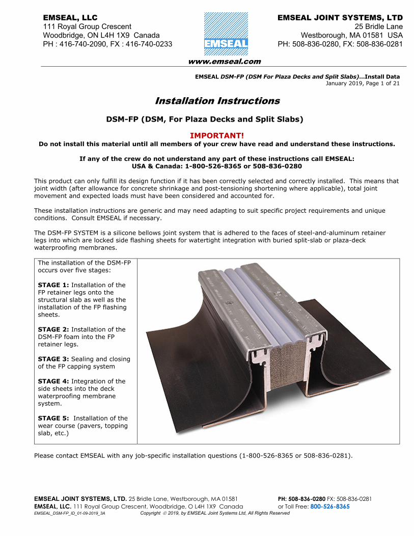
The DSM-FP SYSTEM is a silicone bellows joint system that is adhered to the faces of steel-and-aluminum retainer legs into which are locked side flashing sheets for watertight integration with buried split-slab or plaza-deck waterproofing membranes.
The installation of the DSM-FP occurs over five stages:
STAGE 1: Installation of the FP retainer legs onto the structural slab as well as the installation of the FP flashing sheets.
STAGE 2: Installation of the DSM-FP foam into the FP retainer legs.
STAGE 3: Sealing and closing of the FP capping system
STAGE 4: Integration of the side sheets into the deck waterproofing membrane system.
STAGE 5: Installation of the wear course (pavers, topping slab, etc.)
Please contact EMSEAL with any job-specific installation questions (1-800-526-8365 or 508-836-0281).
EMSEAL DSM-FP (DSM For Plaza Decks and Split Slabs)…Install Data JANUARY 2019, Page 2 of 21
EMSEAL JOINT SYSTEMS, LTD. 25 Bridle Lane, Westborough, MA 01581 PH: 508-836-0280 FX: 508-836-0281 EMSEAL, LLC. 111 Royal Group Crescent, Woodbridge, O L4H 1X9 Canada or Toll Free: 800-526-8365 EMSEAL_DSM-FP_ID_01-09-2019_3A Copyright 2019, by EMSEAL Joint Systems Ltd, All Rights Reserved
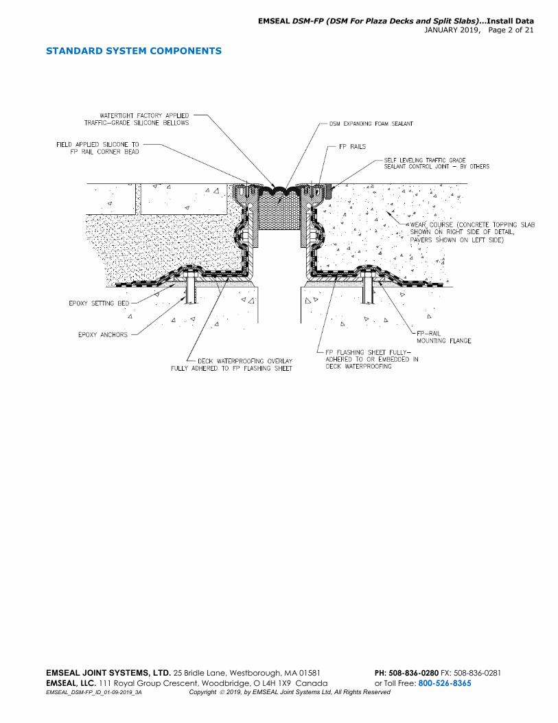
STANDARD SYSTEM COMPONENTS
EMSEAL DSM-FP (DSM For Plaza Decks and Split Slabs)…Install Data JANUARY 2019, Page 3 of 21
EMSEAL JOINT SYSTEMS, LTD. 25 Bridle Lane, Westborough, MA 01581 PH: 508-836-0280 FX: 508-836-0281 EMSEAL, LLC. 111 Royal Group Crescent, Woodbridge, O L4H 1X9 Canada or Toll Free: 800-526-8365 EMSEAL_DSM-FP_ID_01-09-2019_3A Copyright 2019, by EMSEAL Joint Systems Ltd, All Rights Reserved
EQUIPMENT LIST: In addition to a reliable power source, normal tools of the trade and safety equipment as required by the installing contractor’s internal safety program and in compliance with industry standards and local, state and federal safety requirements, the following material and equipment must be on-site before the EMSEAL Technician arrives or before installation can begin:
Crew A crew of 4 is typical when installing this system but could vary with the size and complexity of the job. For Welding Rubber: IMPORTANT: If you are planning to, or will need to, field-weld any of the rubber components, be sure to order an on-loan weld-kit from EMSEAL. On-loan weld kit from EMSEAL For Cutting, Drilling, Screwing, Fastening: 4-inch angle grinder(s) Diamond cup blade(s) for concrete thin “cut-off” blade(s) for metal “Sawz-All” long and short metal cutting blades for sawz all min. 2 ea - Hammer Drills with depth guides min. 6 ea - Hammer drill bits, 3/8-inch diameter,
suitable for masonry/concrete compressed air blower with small gauge extension tube
(for blowing out anchor holes) standard commercial-grade high-speed cordless drills
with adjustable torque settings drill index with sizes 1/32-inch to 1/2-inch minimum high-speed, 3/4-inch, metal countersink bits 5mm (13/64”) and 8mm (5/16”) high speed drill bits
(for preparing new holes in rails and caps at cuts) 6mm taps (for re-tapping the capping-strip screw
holes after you cross-thread a few of them) min. 6 ea – 7/32-inch hex bit socket drill drivers (3/8-
inch drive) 3/8-inch socket adapters (for use in drills) small hand-held metal (fine-toothed) file (for removing
metal burrs after cutting) minimum 6 ea - #3 screw-gun bits Torque-Wrench--long-handled 3/8-inch socket with
adapter to accept #3 screw-gun tip Note: torque wrench must accurately read as low as 60 in-lbs (5.2 ft-lbs; 7 Nm) and as much as 240 in-lbs (20 ft-lbs; 27Nm)--(for final torque setting on capping strip screws).
1/4” diameter Awl
For Mixing and Spreading: heavy duty electric, plug-in, low speed, high
torque drill for mixing thick epoxy min. 2 ea - 3-inch diameter paddle mixers min. 2 ea - 1 ½” diameter “jiffy mixers” minimum 6 ea - 2” margin trowels Clean or unused, 5-gal or larger, plaster/paint
pails to mix epoxy, hold cleaning solvents, etc. For Gunning and Tooling: 20-oz sausage caulk guns (for silicone) Sausage-gun nozzles (cones) 10-oz cartridge caulk guns (for anchor epoxy) min. 3 ea. - ¾” caulk knives Utility knives For Cutting Foam: long-bladed, serrated, chef’s knife (or bread
knife), or hack saw miter box or block Other Miscellaneous Tools and Materials: 2 - plastic spray bottles, (1 bottle with solvent),
and (1 bottle with clean water) Duct tape levels, 2-foot, 4-foot and torpedo-level 100-foot tape measure combination square chalk box with chalk flat bar and small pry bar rubber mallet 5-gal pail of (Acetone* or effective alternative
solvent) box of clean, dry, lint-free, cloth rags vise grips (2-pair) shop Vac extension cords with 4-way box 2 - 9/16” open-end wrenches and/or 9/16”
deep drive sockets & ratchets *Solvents mentioned or referred to are toxic and flammable. Observe solvent manufacturer’s precautions and refer to MSDS, as well as local and federal requirements for handling and use.
EMSEAL DSM-FP (DSM For Plaza Decks and Split Slabs)…Install Data JANUARY 2019, Page 4 of 21
EMSEAL JOINT SYSTEMS, LTD. 25 Bridle Lane, Westborough, MA 01581 PH: 508-836-0280 FX: 508-836-0281 EMSEAL, LLC. 111 Royal Group Crescent, Woodbridge, O L4H 1X9 Canada or Toll Free: 800-526-8365 EMSEAL_DSM-FP_ID_01-09-2019_3A Copyright 2019, by EMSEAL Joint Systems Ltd, All Rights Reserved
STAGE 1: Installation of FP Retainer Legs (rails) and Flashing Sheets The principle used in this installation method for setting the height of the FP System is to tap the mounting flanges of the FP rails down into a wet epoxy-mortar setting bed until the top surface of the joint is at the desired elevation relative to the finished wear-course level. Check that sufficient height between the top of the structural slab (or curb cast onto and pinned into the structural slab) and finished elevation of the topping exists to accommodate the specific FP model being installed. There should be enough room to accommodate the height of the FP System ordered plus at least 1/4 - 3/8-inch (6-9mm) of setting bed.
STEP 1: Prepare Deck Surface Using a grinder or blaster, clean and prepare a 6" wide strip on either side of the joint gap (or if a curb is being cast on which to seat the DSM-FP, similarly prepare the top surface of the curb). The resulting concrete surface must be clean, dry, and free of all dirt and contaminants and must be the correct depth below the finished wear course level. Thoroughly blow clean the deck surface and at least 5-feet of the adjacent work area along the entire joint length. Any significant unevenness in the deck surface or spalling at the joint edge must be repaired with a suitable patching material using proper shelf geometry for spall repair.
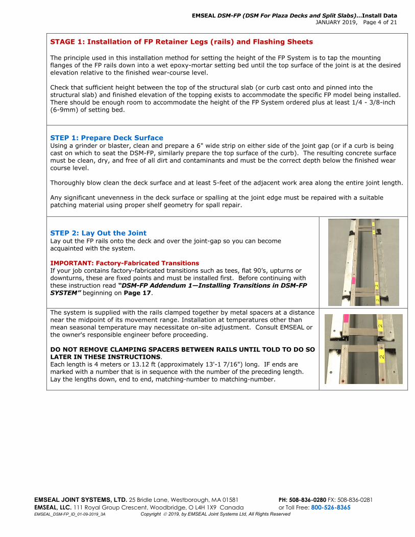
STEP 2: Lay Out the Joint Lay out the FP rails onto the deck and over the joint-gap so you can become acquainted with the system. IMPORTANT: Factory-Fabricated Transitions If your job contains factory-fabricated transitions such as tees, flat 90’s, upturns or downturns, these are fixed points and must be installed first. Before continuing with these instruction read “DSM-FP Addendum 1—Installing Transitions in DSM-FP SYSTEM” beginning on Page 17.
The system is supplied with the rails clamped together by metal spacers at a distance near the midpoint of its movement range. Installation at temperatures other than mean seasonal temperature may necessitate on-site adjustment. Consult EMSEAL or the owner's responsible engineer before proceeding. DO NOT REMOVE CLAMPING SPACERS BETWEEN RAILS UNTIL TOLD TO DO SO LATER IN THESE INSTRUCTIONS. Each length is 4 meters or 13.12 ft (approximately 13'-1 7/16") long. IF ends are marked with a number that is in sequence with the number of the preceding length. Lay the lengths down, end to end, matching-number to matching-number.
EMSEAL DSM-FP (DSM For Plaza Decks and Split Slabs)…Install Data JANUARY 2019, Page 5 of 21
EMSEAL JOINT SYSTEMS, LTD. 25 Bridle Lane, Westborough, MA 01581 PH: 508-836-0280 FX: 508-836-0281 EMSEAL, LLC. 111 Royal Group Crescent, Woodbridge, O L4H 1X9 Canada or Toll Free: 800-526-8365 EMSEAL_DSM-FP_ID_01-09-2019_3A Copyright 2019, by EMSEAL Joint Systems Ltd, All Rights Reserved
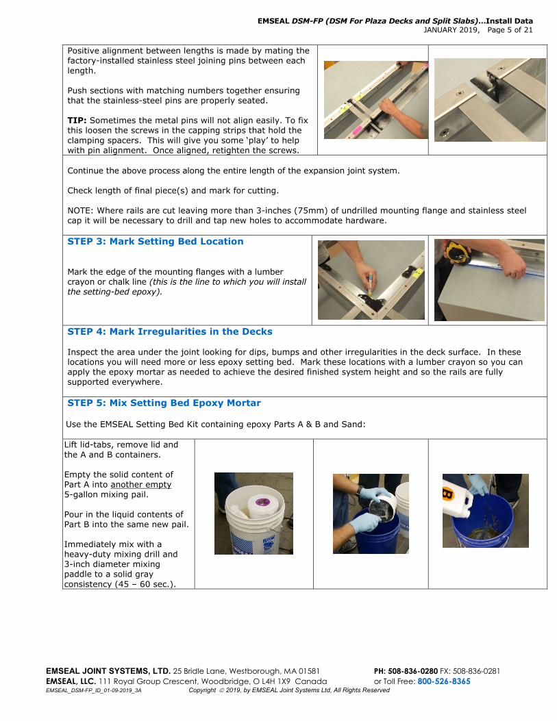
Positive alignment between lengths is made by mating the factory-installed stainless steel joining pins between each length. Push sections with matching numbers together ensuring that the stainless-steel pins are properly seated. TIP: Sometimes the metal pins will not align easily. To fix this loosen the screws in the capping strips that hold the clamping spacers. This will give you some ‘play’ to help with pin alignment. Once aligned, retighten the screws.
Continue the above process along the entire length of the expansion joint system. Check length of final piece(s) and mark for cutting.
NOTE: Where rails are cut leaving more than 3-inches (75mm) of undrilled mounting flange and stainless steel cap it will be necessary to drill and tap new holes to accommodate hardware. STEP 3: Mark Setting Bed Location Mark the edge of the mounting flanges with a lumber crayon or chalk line (this is the line to which you will install the setting-bed epoxy).
STEP 4: Mark Irregularities in the Decks Inspect the area under the joint looking for dips, bumps and other irregularities in the deck surface. In these locations you will need more or less epoxy setting bed. Mark these locations with a lumber crayon so you can apply the epoxy mortar as needed to achieve the desired finished system height and so the rails are fully supported everywhere. STEP 5: Mix Setting Bed Epoxy Mortar Use the EMSEAL Setting Bed Kit containing epoxy Parts A & B and Sand: Lift lid-tabs, remove lid and the A and B containers. Empty the solid content of Part A into another empty 5-gallon mixing pail. Pour in the liquid contents of Part B into the same new pail. Immediately mix with a heavy-duty mixing drill and 3-inch diameter mixing paddle to a solid gray consistency (45 – 60 sec.).
EMSEAL DSM-FP (DSM For Plaza Decks and Split Slabs)…Install Data JANUARY 2019, Page 6 of 21
EMSEAL JOINT SYSTEMS, LTD. 25 Bridle Lane, Westborough, MA 01581 PH: 508-836-0280 FX: 508-836-0281 EMSEAL, LLC. 111 Royal Group Crescent, Woodbridge, O L4H 1X9 Canada or Toll Free: 800-526-8365 EMSEAL_DSM-FP_ID_01-09-2019_3A Copyright 2019, by EMSEAL Joint Systems Ltd, All Rights Reserved
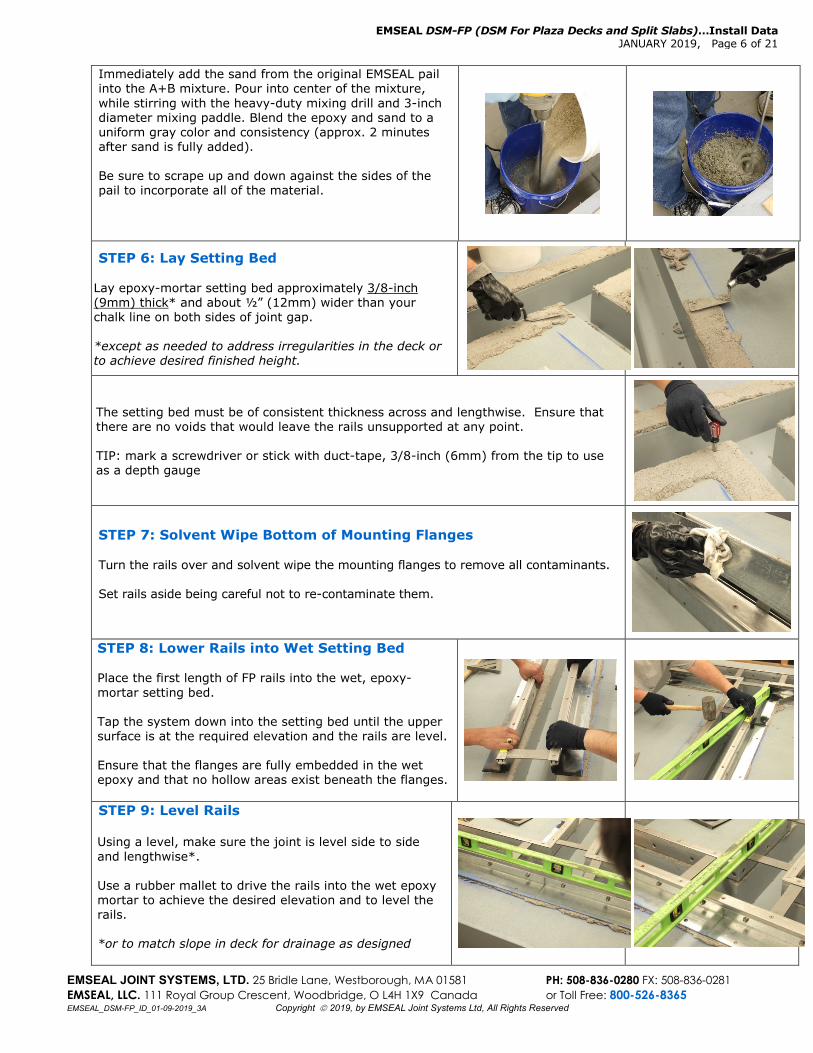
Immediately add the sand from the original EMSEAL pail into the A+B mixture. Pour into center of the mixture, while stirring with the heavy-duty mixing drill and 3-inch diameter mixing paddle. Blend the epoxy and sand to a uniform gray color and consistency (approx. 2 minutes after sand is fully added). Be sure to scrape up and down against the sides of the pail to incorporate all of the material.
STEP 6: Lay Setting Bed Lay epoxy-mortar setting bed approximately 3/8-inch (9mm) thick* and about ½” (12mm) wider than your chalk line on both sides of joint gap. *except as needed to address irregularities in the deck or to achieve desired finished height.
The setting bed must be of consistent thickness across and lengthwise. Ensure that there are no voids that would leave the rails unsupported at any point. TIP: mark a screwdriver or stick with duct-tape, 3/8-inch (6mm) from the tip to use as a depth gauge
STEP 7: Solvent Wipe Bottom of Mounting Flanges Turn the rails over and solvent wipe the mounting flanges to remove all contaminants. Set rails aside being careful not to re-contaminate them.
STEP 8: Lower Rails into Wet Setting Bed Place the first length of FP rails into the wet, epoxy-mortar setting bed. Tap the system down into the setting bed until the upper surface is at the required elevation and the rails are level. Ensure that the flanges are fully embedded in the wet epoxy and that no hollow areas exist beneath the flanges.
STEP 9: Level Rails Using a level, make sure the joint is level side to side and lengthwise*. Use a rubber mallet to drive the rails into the wet epoxy mortar to achieve the desired elevation and to level the rails. *or to match slope in deck for drainage as designed
EMSEAL DSM-FP (DSM For Plaza Decks and Split Slabs)…Install Data JANUARY 2019, Page 7 of 21
EMSEAL JOINT SYSTEMS, LTD. 25 Bridle Lane, Westborough, MA 01581 PH: 508-836-0280 FX: 508-836-0281 EMSEAL, LLC. 111 Royal Group Crescent, Woodbridge, O L4H 1X9 Canada or Toll Free: 800-526-8365 EMSEAL_DSM-FP_ID_01-09-2019_3A Copyright 2019, by EMSEAL Joint Systems Ltd, All Rights Reserved
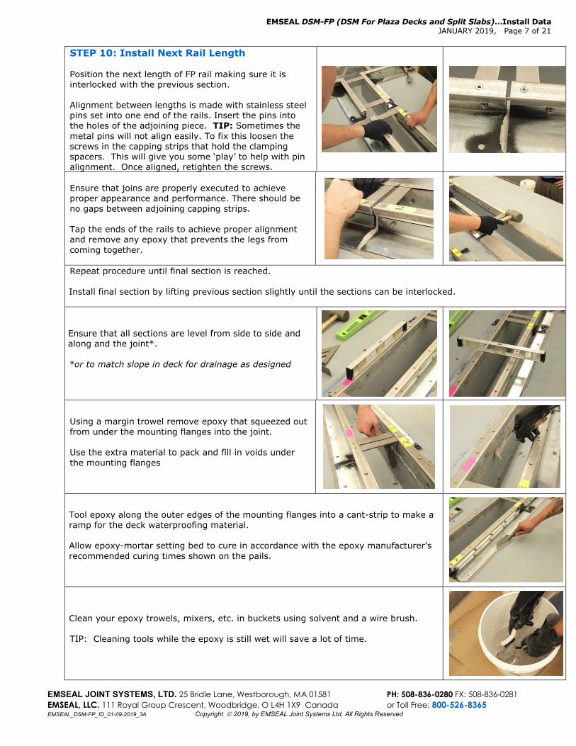
STEP 10: Install Next Rail Length Position the next length of FP rail making sure it is interlocked with the previous section. Alignment between lengths is made with stainless steel pins set into one end of the rails. Insert the pins into the holes of the adjoining piece. TIP: Sometimes the metal pins will not align easily. To fix this loosen the screws in the capping strips that hold the clamping spacers. This will give you some ‘play’ to help with pin alignment. Once aligned, retighten the screws.
Ensure that joins are properly executed to achieve proper appearance and performance. There should be no gaps between adjoining capping strips. Tap the ends of the rails to achieve proper alignment and remove any epoxy that prevents the legs from coming together.
Repeat procedure until final section is reached. Install final section by lifting previous section slightly until the sections can be interlocked.
Ensure that all sections are level from side to side and along and the joint*. *or to match slope in deck for drainage as designed
Using a margin trowel remove epoxy that squeezed out from under the mounting flanges into the joint. Use the extra material to pack and fill in voids under the mounting flanges
Tool epoxy along the outer edges of the mounting flanges into a cant-strip to make a ramp for the deck waterproofing material. Allow epoxy-mortar setting bed to cure in accordance with the epoxy manufacturer's recommended curing times shown on the pails.
Clean your epoxy trowels, mixers, etc. in buckets using solvent and a wire brush. TIP: Cleaning tools while the epoxy is still wet will save a lot of time.
EMSEAL DSM-FP (DSM For Plaza Decks and Split Slabs)…Install Data JANUARY 2019, Page 8 of 21
EMSEAL JOINT SYSTEMS, LTD. 25 Bridle Lane, Westborough, MA 01581 PH: 508-836-0280 FX: 508-836-0281 EMSEAL, LLC. 111 Royal Group Crescent, Woodbridge, O L4H 1X9 Canada or Toll Free: 800-526-8365 EMSEAL_DSM-FP_ID_01-09-2019_3A Copyright 2019, by EMSEAL Joint Systems Ltd, All Rights Reserved
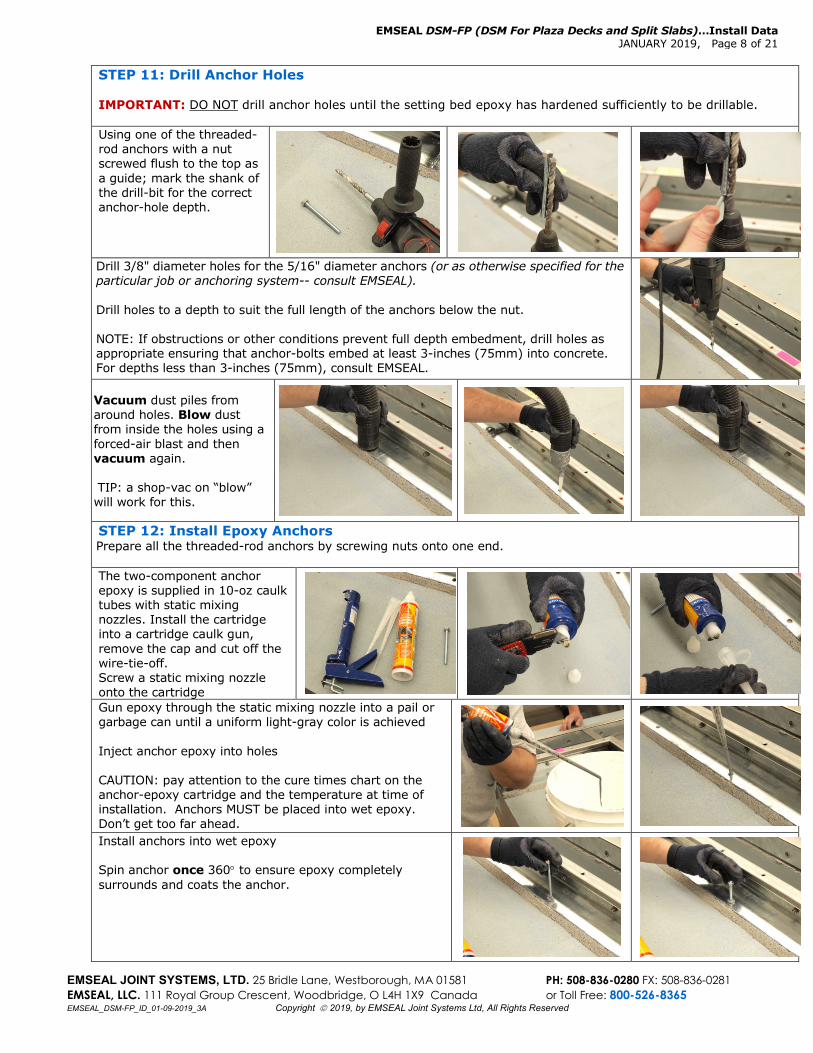
STEP 11: Drill Anchor Holes IMPORTANT: DO NOT drill anchor holes until the setting bed epoxy has hardened sufficiently to be drillable. Using one of the threaded-rod anchors with a nut screwed flush to the top as a guide; mark the shank of the drill-bit for the correct anchor-hole depth.
Drill 3/8" diameter holes for the 5/16" diameter anchors (or as otherwise specified for the particular job or anchoring system-- consult EMSEAL). Drill holes to a depth to suit the full length of the anchors below the nut. NOTE: If obstructions or other conditions prevent full depth embedment, drill holes as appropriate ensuring that anchor-bolts embed at least 3-inches (75mm) into concrete. For depths less than 3-inches (75mm), consult EMSEAL.
Vacuum dust piles from around holes. Blow dust from inside the holes using a forced-air blast and then vacuum again. TIP: a shop-vac on “blow” will work for this.
STEP 12: Install Epoxy Anchors Prepare all the threaded-rod anchors by screwing nuts onto one end. The two-component anchor epoxy is supplied in 10-oz caulk tubes with static mixing nozzles. Install the cartridge into a cartridge caulk gun, remove the cap and cut off the wire-tie-off. Screw a static mixing nozzle onto the cartridge Gun epoxy through the static mixing nozzle into a pail or garbage can until a uniform light-gray color is achieved Inject anchor epoxy into holes CAUTION: pay attention to the cure times chart on the anchor-epoxy cartridge and the temperature at time of installation. Anchors MUST be placed into wet epoxy. Don’t get too far ahead. Install anchors into wet epoxy Spin anchor once 360° to ensure epoxy completely surrounds and coats the anchor.
EMSEAL DSM-FP (DSM For Plaza Decks and Split Slabs)…Install Data JANUARY 2019, Page 9 of 21
EMSEAL JOINT SYSTEMS, LTD. 25 Bridle Lane, Westborough, MA 01581 PH: 508-836-0280 FX: 508-836-0281 EMSEAL, LLC. 111 Royal Group Crescent, Woodbridge, O L4H 1X9 Canada or Toll Free: 800-526-8365 EMSEAL_DSM-FP_ID_01-09-2019_3A Copyright 2019, by EMSEAL Joint Systems Ltd, All Rights Reserved
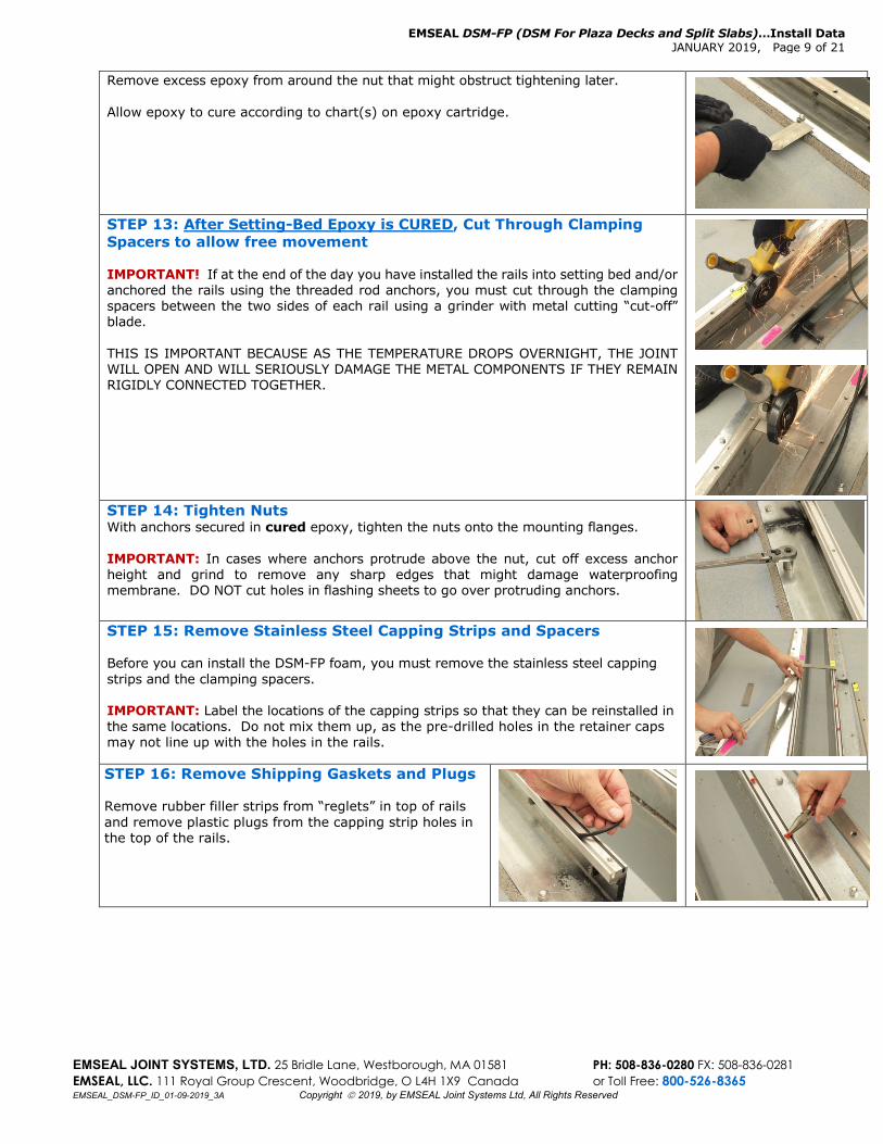
Remove excess epoxy from around the nut that might obstruct tightening later.
Allow epoxy to cure according to chart(s) on epoxy cartridge.
STEP 13: After Setting-Bed Epoxy is CURED, Cut Through Clamping Spacers to allow free movement
IMPORTANT! If at the end of the day you have installed the rails into setting bed and/or anchored the rails using the threaded rod anchors, you must cut through the clamping spacers between the two sides of each rail using a grinder with metal cutting “cut-off” blade. THIS IS IMPORTANT BECAUSE AS THE TEMPERATURE DROPS OVERNIGHT, THE JOINT WILL OPEN AND WILL SERIOUSLY DAMAGE THE METAL COMPONENTS IF THEY REMAIN RIGIDLY CONNECTED TOGETHER.
STEP 14: Tighten Nuts With anchors secured in cured epoxy, tighten the nuts onto the mounting flanges. IMPORTANT: In cases where anchors protrude above the nut, cut off excess anchor height and grind to remove any sharp edges that might damage waterproofing membrane. DO NOT cut holes in flashing sheets to go over protruding anchors.
STEP 15: Remove Stainless Steel Capping Strips and Spacers Before you can install the DSM-FP foam, you must remove the stainless steel capping strips and the clamping spacers. IMPORTANT: Label the locations of the capping strips so that they can be reinstalled in the same locations. Do not mix them up, as the pre-drilled holes in the retainer caps may not line up with the holes in the rails.
STEP 16: Remove Shipping Gaskets and Plugs Remove rubber filler strips from “reglets” in top of rails and remove plastic plugs from the capping strip holes in the top of the rails.
EMSEAL DSM-FP (DSM For Plaza Decks and Split Slabs)…Install Data JANUARY 2019, Page 10 of 21
EMSEAL JOINT SYSTEMS, LTD. 25 Bridle Lane, Westborough, MA 01581 PH: 508-836-0280 FX: 508-836-0281 EMSEAL, LLC. 111 Royal Group Crescent, Woodbridge, O L4H 1X9 Canada or Toll Free: 800-526-8365 EMSEAL_DSM-FP_ID_01-09-2019_3A Copyright 2019, by EMSEAL Joint Systems Ltd, All Rights Reserved
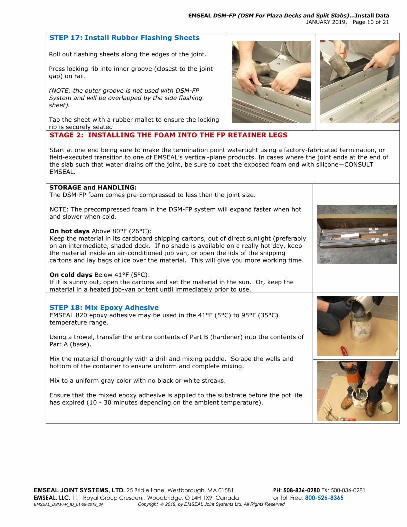
STEP 17: Install Rubber Flashing Sheets Roll out flashing sheets along the edges of the joint. Press locking rib into inner groove (closest to the joint-gap) on rail. (NOTE: the outer groove is not used with DSM-FP System and will be overlapped by the side flashing sheet).
Tap the sheet with a rubber mallet to ensure the locking rib is securely seated
STAGE 2: INSTALLING THE FOAM INTO THE FP RETAINER LEGS Start at one end being sure to make the termination point watertight using a factory-fabricated termination, or field-executed transition to one of EMSEAL’s vertical-plane products. In cases where the joint ends at the end of the slab such that water drains off the joint, be sure to coat the exposed foam end with silicone—CONSULT EMSEAL. STORAGE and HANDLING: The DSM-FP foam comes pre-compressed to less than the joint size. NOTE: The precompressed foam in the DSM-FP system will expand faster when hot and slower when cold. On hot days Above 80°F (26°C): Keep the material in its cardboard shipping cartons, out of direct sunlight (preferably on an intermediate, shaded deck. If no shade is available on a really hot day, keep the material inside an air-conditioned job van, or open the lids of the shipping cartons and lay bags of ice over the material. This will give you more working time. On cold days Below 41°F (5°C): If it is sunny out, open the cartons and set the material in the sun. Or, keep the material in a heated job-van or tent until immediately prior to use.
STEP 18: Mix Epoxy Adhesive EMSEAL 820 epoxy adhesive may be used in the 41°F (5°C) to 95°F (35°C) temperature range.
Using a trowel, transfer the entire contents of Part B (hardener) into the contents of Part A (base). Mix the material thoroughly with a drill and mixing paddle. Scrape the walls and bottom of the container to ensure uniform and complete mixing. Mix to a uniform gray color with no black or white streaks. Ensure that the mixed epoxy adhesive is applied to the substrate before the pot life has expired (10 - 30 minutes depending on the ambient temperature).
EMSEAL DSM-FP (DSM For Plaza Decks and Split Slabs)…Install Data JANUARY 2019, Page 11 of 21
EMSEAL JOINT SYSTEMS, LTD. 25 Bridle Lane, Westborough, MA 01581 PH: 508-836-0280 FX: 508-836-0281 EMSEAL, LLC. 111 Royal Group Crescent, Woodbridge, O L4H 1X9 Canada or Toll Free: 800-526-8365 EMSEAL_DSM-FP_ID_01-09-2019_3A Copyright 2019, by EMSEAL Joint Systems Ltd, All Rights Reserved
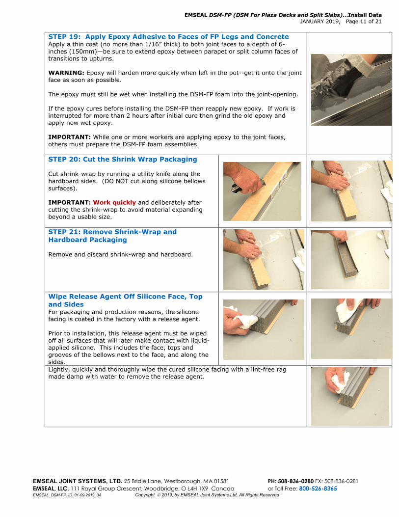
STEP 19: Apply Epoxy Adhesive to Faces of FP Legs and Concrete Apply a thin coat (no more than 1/16” thick) to both joint faces to a depth of 6-inches (150mm)—be sure to extend epoxy between parapet or split column faces of transitions to upturns. WARNING: Epoxy will harden more quickly when left in the pot--get it onto the joint face as soon as possible. The epoxy must still be wet when installing the DSM-FP foam into the joint-opening. If the epoxy cures before installing the DSM-FP then reapply new epoxy. If work is interrupted for more than 2 hours after initial cure then grind the old epoxy and apply new wet epoxy. IMPORTANT: While one or more workers are applying epoxy to the joint faces, others must prepare the DSM-FP foam assemblies.
STEP 20: Cut the Shrink Wrap Packaging Cut shrink-wrap by running a utility knife along the hardboard sides. (DO NOT cut along silicone bellows surfaces). IMPORTANT: Work quickly and deliberately after cutting the shrink-wrap to avoid material expanding beyond a usable size.
STEP 21: Remove Shrink-Wrap and Hardboard Packaging Remove and discard shrink-wrap and hardboard.
Wipe Release Agent Off Silicone Face, Top and Sides For packaging and production reasons, the silicone facing is coated in the factory with a release agent. Prior to installation, this release agent must be wiped off all surfaces that will later make contact with liquid-applied silicone. This includes the face, tops and grooves of the bellows next to the face, and along the sides.
Lightly, quickly and thoroughly wipe the cured silicone facing with a lint-free rag made damp with water to remove the release agent.
EMSEAL DSM-FP (DSM For Plaza Decks and Split Slabs)…Install Data JANUARY 2019, Page 12 of 21
EMSEAL JOINT SYSTEMS, LTD. 25 Bridle Lane, Westborough, MA 01581 PH: 508-836-0280 FX: 508-836-0281 EMSEAL, LLC. 111 Royal Group Crescent, Woodbridge, O L4H 1X9 Canada or Toll Free: 800-526-8365 EMSEAL_DSM-FP_ID_01-09-2019_3A Copyright 2019, by EMSEAL Joint Systems Ltd, All Rights Reserved
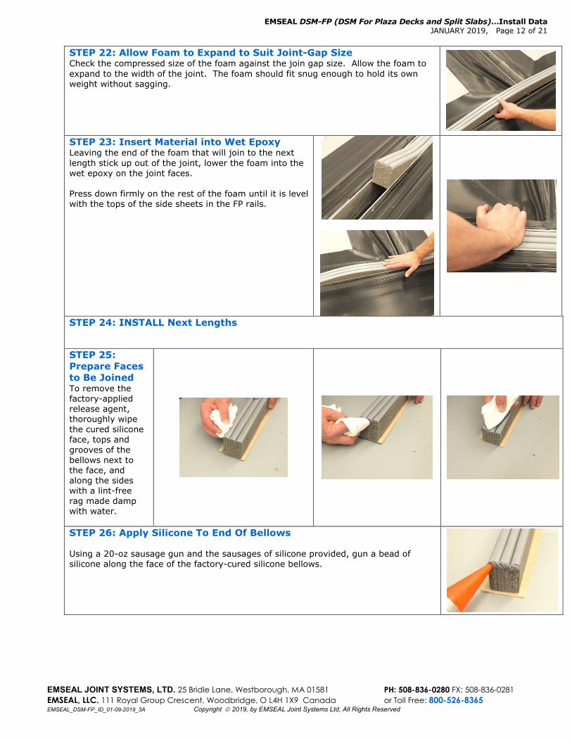
STEP 22: Allow Foam to Expand to Suit Joint-Gap Size Check the compressed size of the foam against the join gap size. Allow the foam to expand to the width of the joint. The foam should fit snug enough to hold its own weight without sagging.
STEP 23: Insert Material into Wet Epoxy Leaving the end of the foam that will join to the next length stick up out of the joint, lower the foam into the wet epoxy on the joint faces. Press down firmly on the rest of the foam until it is level with the tops of the side sheets in the FP rails.
STEP 24: INSTALL Next Lengths STEP 25: Prepare Faces to Be Joined To remove the factory-applied release agent, thoroughly wipe the cured silicone face, tops and grooves of the bellows next to the face, and along the sides with a lint-free rag made damp with water.
STEP 26: Apply Silicone To End Of Bellows Using a 20-oz sausage gun and the sausages of silicone provided, gun a bead of silicone along the face of the factory-cured silicone bellows.
EMSEAL DSM-FP (DSM For Plaza Decks and Split Slabs)…Install Data JANUARY 2019, Page 13 of 21
EMSEAL JOINT SYSTEMS, LTD. 25 Bridle Lane, Westborough, MA 01581 PH: 508-836-0280 FX: 508-836-0281 EMSEAL, LLC. 111 Royal Group Crescent, Woodbridge, O L4H 1X9 Canada or Toll Free: 800-526-8365 EMSEAL_DSM-FP_ID_01-09-2019_3A Copyright 2019, by EMSEAL Joint Systems Ltd, All Rights Reserved
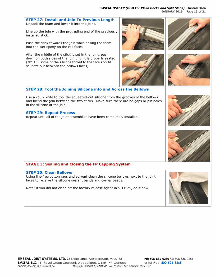
STEP 27: Install and Join To Previous Length Unpack the foam and lower it into the joint. Line up the join with the protruding end of the previously installed stick. Push the stick towards the join while easing the foam into the wet epoxy on the rail faces. After the middle of the stick is set in the joint, push down on both sides of the join until it is properly seated. (NOTE: Some of the silicone tooled to the face should squeeze out between the bellows faces).
STEP 28: Tool the Joining Silicone into and Across the Bellows Use a caulk knife to tool the squeezed-out silicone from the grooves of the bellows and blend the join between the two sticks. Make sure there are no gaps or pin holes in the silicone at the join. STEP 29: Repeat Process Repeat until all of the joint assemblies have been completely installed.
STAGE 3: Sealing and Closing the FP Capping System STEP 30: Clean Bellows Using lint-free cotton rags and solvent clean the silicone bellows next to the joint faces to receive the silicone sealant bands and corner beads. Note: if you did not clean off the factory release agent in STEP 25, do it now.
EMSEAL DSM-FP (DSM For Plaza Decks and Split Slabs)…Install Data JANUARY 2019, Page 14 of 21
EMSEAL JOINT SYSTEMS, LTD. 25 Bridle Lane, Westborough, MA 01581 PH: 508-836-0280 FX: 508-836-0281 EMSEAL, LLC. 111 Royal Group Crescent, Woodbridge, O L4H 1X9 Canada or Toll Free: 800-526-8365 EMSEAL_DSM-FP_ID_01-09-2019_3A Copyright 2019, by EMSEAL Joint Systems Ltd, All Rights Reserved
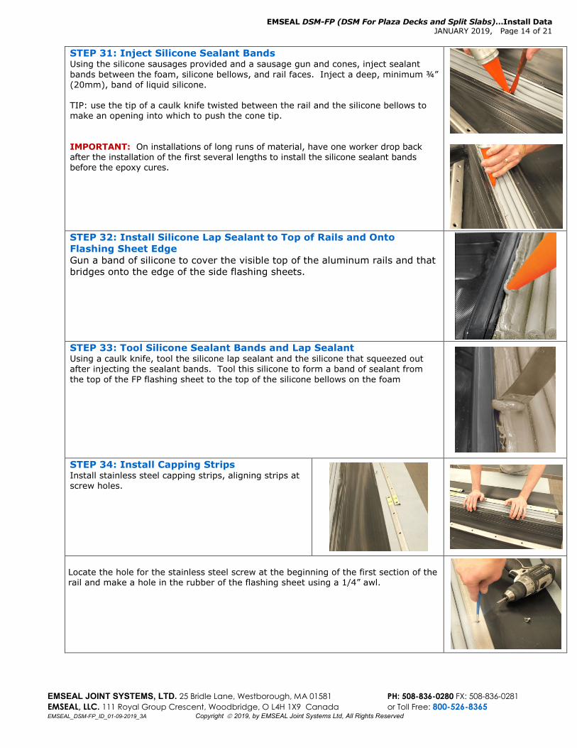
STEP 31: Inject Silicone Sealant Bands Using the silicone sausages provided and a sausage gun and cones, inject sealant bands between the foam, silicone bellows, and rail faces. Inject a deep, minimum ¾” (20mm), band of liquid silicone. TIP: use the tip of a caulk knife twisted between the rail and the silicone bellows to make an opening into which to push the cone tip. IMPORTANT: On installations of long runs of material, have one worker drop back after the installation of the first several lengths to install the silicone sealant bands before the epoxy cures.
STEP 32: Install Silicone Lap Sealant to Top of Rails and Onto Flashing Sheet Edge Gun a band of silicone to cover the visible top of the aluminum rails and that bridges onto the edge of the side flashing sheets.
STEP 33: Tool Silicone Sealant Bands and Lap Sealant Using a caulk knife, tool the silicone lap sealant and the silicone that squeezed out after injecting the sealant bands. Tool this silicone to form a band of sealant from the top of the FP flashing sheet to the top of the silicone bellows on the foam
STEP 34: Install Capping Strips Install stainless steel capping strips, aligning strips at screw holes.
Locate the hole for the stainless steel screw at the beginning of the first section of the rail and make a hole in the rubber of the flashing sheet using a 1/4” awl.
EMSEAL DSM-FP (DSM For Plaza Decks and Split Slabs)…Install Data JANUARY 2019, Page 15 of 21
EMSEAL JOINT SYSTEMS, LTD. 25 Bridle Lane, Westborough, MA 01581 PH: 508-836-0280 FX: 508-836-0281 EMSEAL, LLC. 111 Royal Group Crescent, Woodbridge, O L4H 1X9 Canada or Toll Free: 800-526-8365 EMSEAL_DSM-FP_ID_01-09-2019_3A Copyright 2019, by EMSEAL Joint Systems Ltd, All Rights Reserved
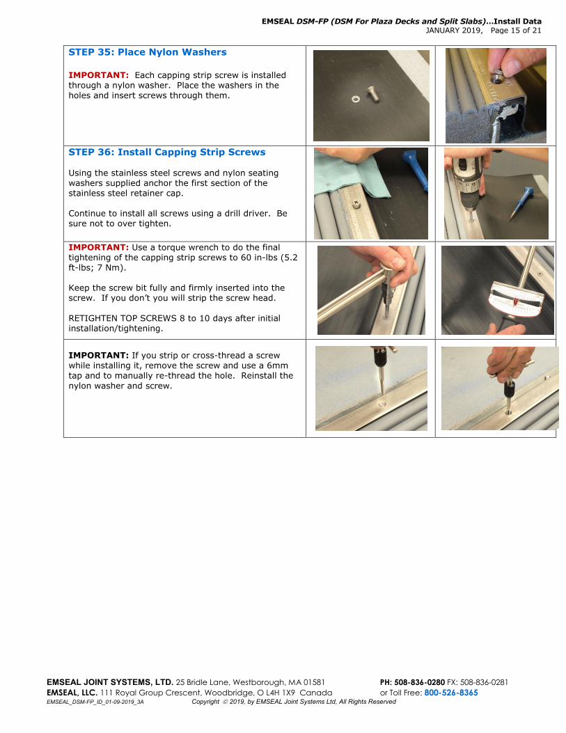
STEP 35: Place Nylon Washers IMPORTANT: Each capping strip screw is installed through a nylon washer. Place the washers in the holes and insert screws through them.
STEP 36: Install Capping Strip Screws Using the stainless steel screws and nylon seating washers supplied anchor the first section of the stainless steel retainer cap. Continue to install all screws using a drill driver. Be sure not to over tighten.
IMPORTANT: Use a torque wrench to do the final tightening of the capping strip screws to 60 in-lbs (5.2 ft-lbs; 7 Nm). Keep the screw bit fully and firmly inserted into the screw. If you don’t you will strip the screw head. RETIGHTEN TOP SCREWS 8 to 10 days after initial installation/tightening. IMPORTANT: If you strip or cross-thread a screw while installing it, remove the screw and use a 6mm tap and to manually re-thread the hole. Reinstall the nylon washer and screw.
EMSEAL DSM-FP (DSM For Plaza Decks and Split Slabs)…Install Data JANUARY 2019, Page 16 of 21
EMSEAL JOINT SYSTEMS, LTD. 25 Bridle Lane, Westborough, MA 01581 PH: 508-836-0280 FX: 508-836-0281 EMSEAL, LLC. 111 Royal Group Crescent, Woodbridge, O L4H 1X9 Canada or Toll Free: 800-526-8365 EMSEAL_DSM-FP_ID_01-09-2019_3A Copyright 2019, by EMSEAL Joint Systems Ltd, All Rights Reserved
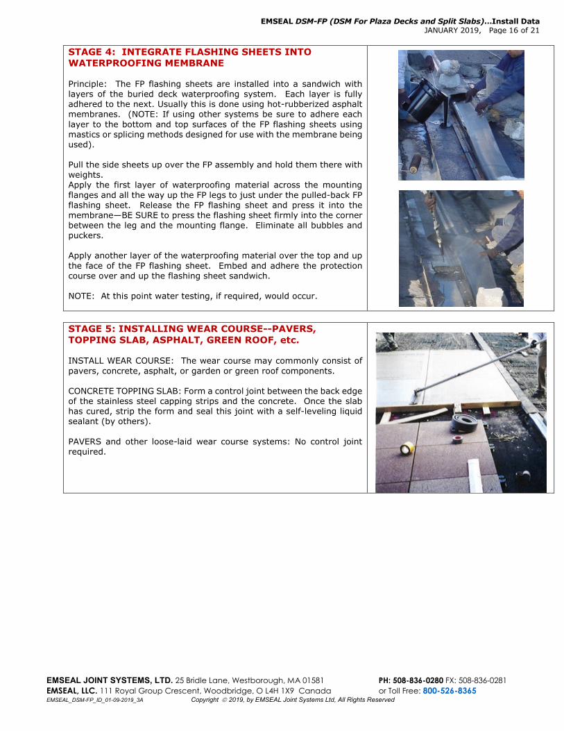
STAGE 4: INTEGRATE FLASHING SHEETS INTO WATERPROOFING MEMBRANE Principle: The FP flashing sheets are installed into a sandwich with layers of the buried deck waterproofing system. Each layer is fully adhered to the next. Usually this is done using hot-rubberized asphalt membranes. (NOTE: If using other systems be sure to adhere each layer to the bottom and top surfaces of the FP flashing sheets using mastics or splicing methods designed for use with the membrane being used). Pull the side sheets up over the FP assembly and hold them there with weights. Apply the first layer of waterproofing material across the mounting flanges and all the way up the FP legs to just under the pulled-back FP flashing sheet. Release the FP flashing sheet and press it into the membrane—BE SURE to press the flashing sheet firmly into the corner between the leg and the mounting flange. Eliminate all bubbles and puckers. Apply another layer of the waterproofing material over the top and up the face of the FP flashing sheet. Embed and adhere the protection course over and up the flashing sheet sandwich. NOTE: At this point water testing, if required, would occur.
STAGE 5: INSTALLING WEAR COURSE--PAVERS, TOPPING SLAB, ASPHALT, GREEN ROOF, etc. INSTALL WEAR COURSE: The wear course may commonly consist of pavers, concrete, asphalt, or garden or green roof components. CONCRETE TOPPING SLAB: Form a control joint between the back edge of the stainless steel capping strips and the concrete. Once the slab has cured, strip the form and seal this joint with a self-leveling liquid sealant (by others). PAVERS and other loose-laid wear course systems: No control joint required.
EMSEAL DSM-FP (DSM For Plaza Decks and Split Slabs)…Install Data JANUARY 2019, Page 17 of 21
EMSEAL JOINT SYSTEMS, LTD. 25 Bridle Lane, Westborough, MA 01581 PH: 508-836-0280 FX: 508-836-0281 EMSEAL, LLC. 111 Royal Group Crescent, Woodbridge, O L4H 1X9 Canada or Toll Free: 800-526-8365 EMSEAL_DSM-FP_ID_01-09-2019_3A Copyright 2019, by EMSEAL Joint Systems Ltd, All Rights Reserved
DSM-FP Addendum 1: Installing Transitions in DSM-FP SYSTEM
IMPORTANT! This is an addendum to “Installation Instructions: DSM-FP (DSM For Plaza Decks and Split Slabs). Do not install this material until all members of your crew have read and understand all instructions. If any of the crew do not understand any part of these instructions call EMSEAL: USA & Canada: 1-800-526-8365 or 508-836-0280 INSTALLING TRANSITIONS AND TERMINATIONS Where expansion joints begin, end and run adjacent to, over, under, or around obstructions such as walls, columns, curbs, sidewalks, planters etc., are typically where leaks persist even after straight runs of joints have been properly sealed. Options exist to properly seal these areas. Transitions and Terminations in Metal Parts: It is usual for the contractor to order factory-fabricated transitions and terminations, as welded assemblies. The components that make up any factory-fabricated item are welded together in the configuration represented by contractor-supplied drawings and dimensions.
Transitions and Terminations in the Side Flashing Sheets: NOTE: It is critical to achieving watertightness that wherever a transition or termination exists, the side flashing sheets be properly welded to follow all contours at the condition so that they may be properly integrated with the deck waterproofing materials. It is possible following proper training from an EMSEAL field technician for the contractor to fabricate transitions and terminations in the heat-weldable side flashing sheets in the field. However, it is more efficient and usual to order transitions and terminations in the side flashing sheets as factory-fabricated, welded items along with the corresponding welded metal parts. The components that make up any factory-fabricated item would be welded together in the configuration represented by contractor-supplied drawings and dimensions. NOTE: It is difficult to accurately represent all substrate contours that the side flashing sheets will come in contact with. For this reason factory-welded side sheets cannot be guaranteed to fit and may require field modification by the contractor. Transitions and Terminations in DSM-FP Foam: Most transitions and terminations in the foam are planned for in consultation with EMSEAL at time of ordering. Some transitions (like curb transitions and treads and risers for example) are factory-fabricated by EMSEAL to the contractors’ field measurements. Other transitions and terminations are field-assembled using custom components ordered as agreed. For most flat changes in direction in the horizontal plane, EMSEAL supplies the DSM-FP SYSTEM assembly configured for field joining at the change in direction. In addition connection of the transition pieces is executed at butt joins to straight lengths using methods represented in principle in these instructions and/or as trained by an EMSEAL field technician.
Welded End-Dam Terminations at Vertical-Plane Terminations: Welded end-dam terminations in flashing sheets at end of joint runs are required wherever the joint ends against a perimeter pour, curb, column or anywhere the deck waterproofing terminates on a vertical surface. An end-dam consists of a folded and welded “boot” in the FP flashing sheet that is embedded and covered in waterproofing membrane materials and is mechanically fixed to the vertical substrate with a termination bar and sealant. The wear-course or topping slab is poured up to and over this termination point and the control joint formed by the pour is sealed with a liquid sealant by others. Welded end-dam terminations can be provided factory made by EMSEAL to field measurements or can be field executed. Instruction for proper field welding is available from the on-site EMSEAL technician. Contact EMSEAL to coordinate instruction.
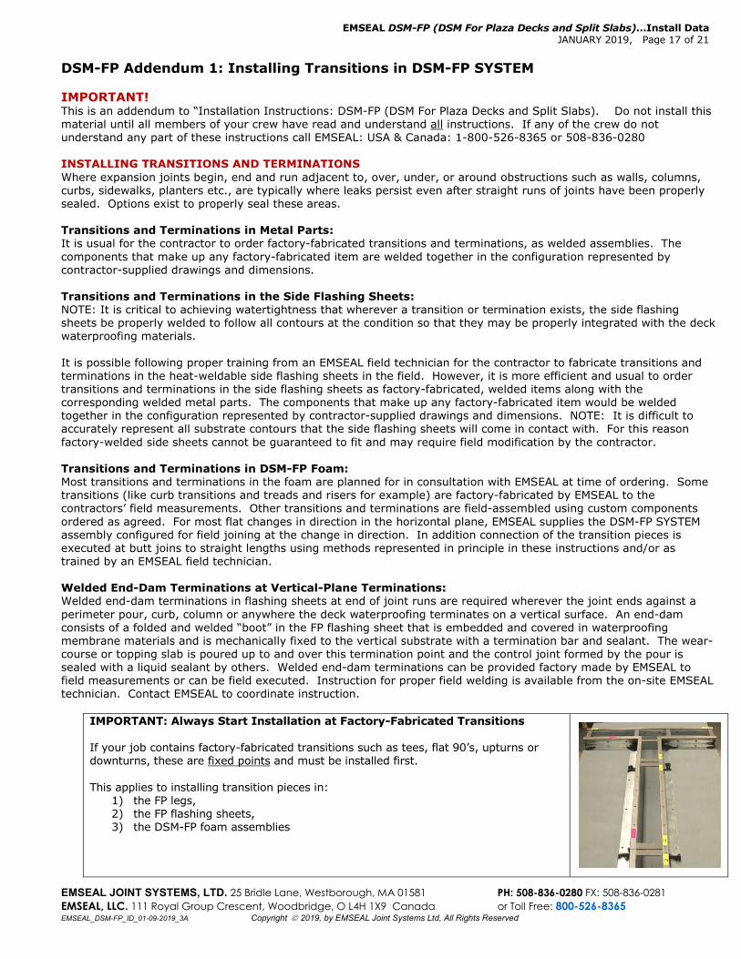
IMPORTANT: Always Start Installation at Factory-Fabricated Transitions If your job contains factory-fabricated transitions such as tees, flat 90’s, upturns or downturns, these are fixed points and must be installed first. This applies to installing transition pieces in:
1) the FP legs, 2) the FP flashing sheets, 3) the DSM-FP foam assemblies
EMSEAL DSM-FP (DSM For Plaza Decks and Split Slabs)…Install Data JANUARY 2019, Page 18 of 21
EMSEAL JOINT SYSTEMS, LTD. 25 Bridle Lane, Westborough, MA 01581 PH: 508-836-0280 FX: 508-836-0281 EMSEAL, LLC. 111 Royal Group Crescent, Woodbridge, O L4H 1X9 Canada or Toll Free: 800-526-8365 EMSEAL_DSM-FP_ID_01-09-2019_3A Copyright 2019, by EMSEAL Joint Systems Ltd, All Rights Reserved
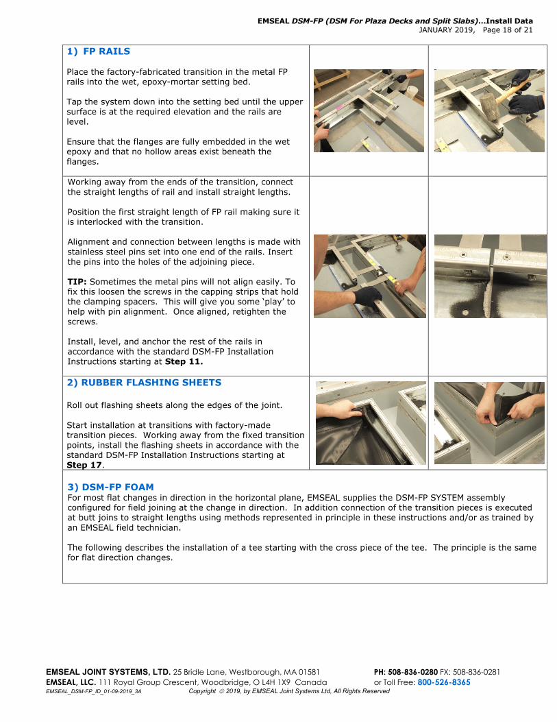
1) FP RAILS Place the factory-fabricated transition in the metal FP rails into the wet, epoxy-mortar setting bed. Tap the system down into the setting bed until the upper surface is at the required elevation and the rails are level. Ensure that the flanges are fully embedded in the wet epoxy and that no hollow areas exist beneath the flanges.
Working away from the ends of the transition, connect the straight lengths of rail and install straight lengths. Position the first straight length of FP rail making sure it is interlocked with the transition. Alignment and connection between lengths is made with stainless steel pins set into one end of the rails. Insert the pins into the holes of the adjoining piece. TIP: Sometimes the metal pins will not align easily. To fix this loosen the screws in the capping strips that hold the clamping spacers. This will give you some ‘play’ to help with pin alignment. Once aligned, retighten the screws. Install, level, and anchor the rest of the rails in accordance with the standard DSM-FP Installation Instructions starting at Step 11.
2) RUBBER FLASHING SHEETS Roll out flashing sheets along the edges of the joint. Start installation at transitions with factory-made transition pieces. Working away from the fixed transition points, install the flashing sheets in accordance with the standard DSM-FP Installation Instructions starting at Step 17.
3) DSM-FP FOAM For most flat changes in direction in the horizontal plane, EMSEAL supplies the DSM-FP SYSTEM assembly configured for field joining at the change in direction. In addition connection of the transition pieces is executed at butt joins to straight lengths using methods represented in principle in these instructions and/or as trained by an EMSEAL field technician. The following describes the installation of a tee starting with the cross piece of the tee. The principle is the same for flat direction changes.
EMSEAL DSM-FP (DSM For Plaza Decks and Split Slabs)…Install Data JANUARY 2019, Page 19 of 21
EMSEAL JOINT SYSTEMS, LTD. 25 Bridle Lane, Westborough, MA 01581 PH: 508-836-0280 FX: 508-836-0281 EMSEAL, LLC. 111 Royal Group Crescent, Woodbridge, O L4H 1X9 Canada or Toll Free: 800-526-8365 EMSEAL_DSM-FP_ID_01-09-2019_3A Copyright 2019, by EMSEAL Joint Systems Ltd, All Rights Reserved
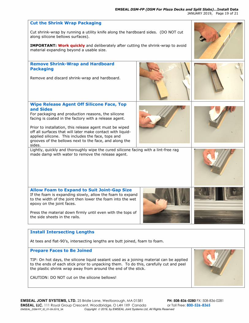
Cut the Shrink Wrap Packaging Cut shrink-wrap by running a utility knife along the hardboard sides. (DO NOT cut along silicone bellows surfaces). IMPORTANT: Work quickly and deliberately after cutting the shrink-wrap to avoid material expanding beyond a usable size.
Remove Shrink-Wrap and Hardboard Packaging Remove and discard shrink-wrap and hardboard.
Wipe Release Agent Off Silicone Face, Top and Sides For packaging and production reasons, the silicone facing is coated in the factory with a release agent. Prior to installation, this release agent must be wiped off all surfaces that will later make contact with liquid-applied silicone. This includes the face, tops and grooves of the bellows next to the face, and along the sides.
Lightly, quickly and thoroughly wipe the cured silicone facing with a lint-free rag made damp with water to remove the release agent.
Allow Foam to Expand to Suit Joint-Gap Size If the foam is expanding slowly, allow the foam to expand to the width of the joint then lower the foam into the wet epoxy on the joint faces. Press the material down firmly until even with the tops of the side sheets in the rails.
Install Intersecting Lengths At tees and flat-90’s, intersecting lengths are butt joined, foam to foam. Prepare Faces to Be Joined TIP: On hot days, the silicone liquid sealant used as a joining material can be applied to the ends of each stick prior to unpacking them. To do this, carefully cut and peel the plastic shrink wrap away from around the end of the stick. CAUTION: DO NOT cut on the silicone bellows!
EMSEAL DSM-FP (DSM For Plaza Decks and Split Slabs)…Install Data JANUARY 2019, Page 20 of 21
EMSEAL JOINT SYSTEMS, LTD. 25 Bridle Lane, Westborough, MA 01581 PH: 508-836-0280 FX: 508-836-0281 EMSEAL, LLC. 111 Royal Group Crescent, Woodbridge, O L4H 1X9 Canada or Toll Free: 800-526-8365 EMSEAL_DSM-FP_ID_01-09-2019_3A Copyright 2019, by EMSEAL Joint Systems Ltd, All Rights Reserved
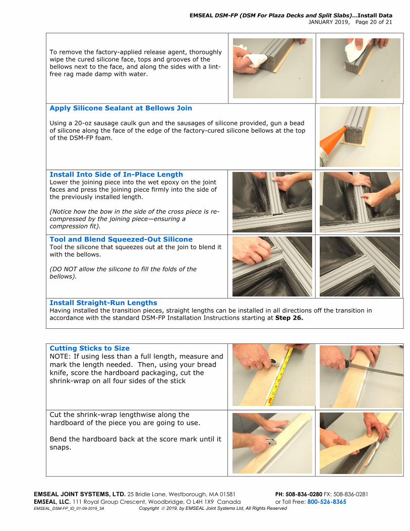
To remove the factory-applied release agent, thoroughly wipe the cured silicone face, tops and grooves of the bellows next to the face, and along the sides with a lint-free rag made damp with water.
Apply Silicone Sealant at Bellows Join Using a 20-oz sausage caulk gun and the sausages of silicone provided, gun a bead of silicone along the face of the edge of the factory-cured silicone bellows at the top of the DSM-FP foam.
Install Into Side of In-Place Length Lower the joining piece into the wet epoxy on the joint faces and press the joining piece firmly into the side of the previously installed length. (Notice how the bow in the side of the cross piece is re-compressed by the joining piece—ensuring a compression fit).
Tool and Blend Squeezed-Out Silicone Tool the silicone that squeezes out at the join to blend it with the bellows. (DO NOT allow the silicone to fill the folds of the bellows).
Install Straight-Run Lengths Having installed the transition pieces, straight lengths can be installed in all directions off the transition in accordance with the standard DSM-FP Installation Instructions starting at Step 26.
Cutting Sticks to Size NOTE: If using less than a full length, measure and mark the length needed. Then, using your bread knife, score the hardboard packaging, cut the shrink-wrap on all four sides of the stick
Cut the shrink-wrap lengthwise along the hardboard of the piece you are going to use. Bend the hardboard back at the score mark until it snaps.
EMSEAL DSM-FP (DSM For Plaza Decks and Split Slabs)…Install Data JANUARY 2019, Page 21 of 21
EMSEAL JOINT SYSTEMS, LTD. 25 Bridle Lane, Westborough, MA 01581 PH: 508-836-0280 FX: 508-836-0281 EMSEAL, LLC. 111 Royal Group Crescent, Woodbridge, O L4H 1X9 Canada or Toll Free: 800-526-8365 EMSEAL_DSM-FP_ID_01-09-2019_3A Copyright 2019, by EMSEAL Joint Systems Ltd, All Rights Reserved
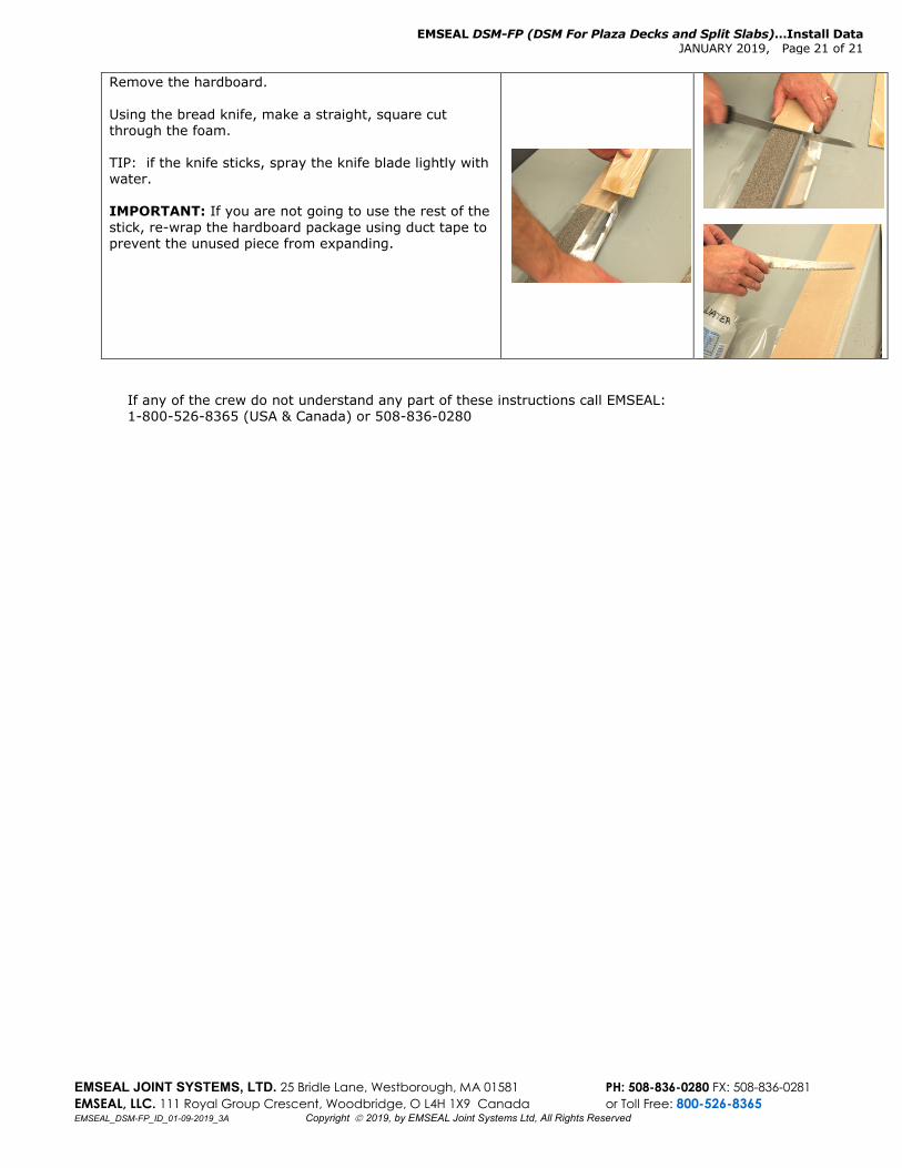
Remove the hardboard. Using the bread knife, make a straight, square cut through the foam. TIP: if the knife sticks, spray the knife blade lightly with water. IMPORTANT: If you are not going to use the rest of the stick, re-wrap the hardboard package using duct tape to prevent the unused piece from expanding.
If any of the crew do not understand any part of these instructions call EMSEAL: 1-800-526-8365 (USA & Canada) or 508-836-0280