emulation of the ip core network for testing of the
TRANSCRIPT

Technical report, IDE0959, November 2009
Emulation of the IP Core Network for Testing of
the Service GPRS Support Node (SGSN)
Routing Application
Master’s Thesis in Computer Network Engineering
Hossein Torkaman
School of Information Science, Computer and Electrical Engineering Halmstad University


Emulation of the IP Core Network for Testing of the Service GPRS Support Node (SGSN) Routing Application
Master’s thesis in Computer Network Engineering
School of Information Science, Computer and Electrical Engineering Halmstad University
Box 823, S-301 18 Halmstad, Sweden
November 2009

Description of cover page picture: IP Core Network picture on GPRS Networks.

Preface The following report is based on the data and information gathered through literature studies, Ericsson’s Intranet documents and other several GPRS standards published by 3rd Generation Partnership Project (3GPP), observations, emulating different IP core network scenarios, meetings and executed experiments during December 2008 - August 2009 at Ericsson AB Lindholmen. The input martial to this thesis formed primarily by Internet Protocols and Drivers section in Product Development Department Packet Core at Ericsson AB, Göteborg, Sweden with leadership of Gunilla Zachrisson, my supervisor, to whom I should give an immense thank you due to her kind guidance on each phase of project and for her valuable supports on the implementation of improvements. I am also thankful to my manager, Matthew Crockett, who also made me feel welcomed at Ericsson AB Lindholmen. A big thanks is also directed to my supervisor at Halmstad University, Tony Larsson, for pointing me in the right direction and for the feedback regarding the performance of the project. I would also like to use this opportunity to thank Colin Taylor and Daniel Nilsson and all other colleagues at Ericsson, for interrupting their busy schedules in order to provide me with their technical feedback and experience. Hossein Torkaman Halmstad University, November 2009
i

ii
Abstract This thesis aims to investigate a method and tool for emulation of the General Packet Radio Service (GPRS) core network needed as an environment to test the routing functionality. GPRS is the most widely adopted mobile packet data delivery technology in the world. It utilizes an Intranet Protocol (IP)-based core network and involves significant changes to the way the Global System for Mobile communications (GSM) air interface is structured. It also forms the basis of the future structure of mobile network transmission and switching. The Serving GPRS Support Node (SGSN) is the most fundamental node in GPRS. Ericsson produces and manages an increasing number of SGSN nodes in the world. One of main functionalities of SGSN node is to forward IP packets according to the destination address in the IP header on IP core network. In each new release of SGSN, or when implementation or upgrades have been done on routing application on SGSN, design and test engineers at Ericsson need to emulate the IP core network. This must be done with use of many routers to generate huge amounts of data that can simulate the real world IP core network. The major goal of this thesis was to analyze and verifying the use of a suitable and economical solution to emulating IP Core Network of the GPRS system for testing of different functionality of the routing application running in SGSN , instead of building up a physical Core Network with different infrastructure and many routers. The method chosen for emulating the IP core network with many routers, and investigated in the thesis, is based on a Cisco simulator called “Dynamips”, which runs many actual Cisco Internetwork Operating Systems (IOS) with many different models of Cisco products in a virtual environment on Windows or Linux platforms. With this simulator, engineers at Ericsson will be able to use this simulator to emulate IP core network easily and efficiently to accomplish system test cases. A conclusion of this work is that Dynamips could be used to emulate many complicated IP core network scenarios, with many routers to generate huge amounts of data to simulate the real world IP core network. The emulated system fulfils its purpose for testing of the routing application of SGSN regarding different functionality and characteristics. This is done to ensure and verify that SGSN routing application meets its functional and technical requirements, and also helps to find undiscovered errors as well as helps to ensure that the individual components of routing application on SGSN are working correctly.
iii
Abbreviations 3GPP 3rd Generation Partnership Project Appl-C Application-control plane Appl-U Application-user plane AS Autonomous System ASE Autonomous System External ATM Asynchronous Transfer Mode BFD Bi-directional Forwarding Detection BGP Border Gateway Protocol BS Billing System BSC Base Station Controller CGF Charging Gateway Function CS Circuit Switching DNS Domain Name System EBGP External Border Gateway Protocol FE Forwarding Engine GGSN Gateway GPRS Support Node: GPRS General Packet Radio Service GRE Generic Routing Encapsulation GSM Global System for Mobile communications GSN GPRS Support Nodes IBGP Internal Border Gateway Protocol ICMP Internet Control Message Protocol IOS Cisco Internetwork Operating Systems IP Internet Protocol IP Intranet Protocol IPSec IP Security Protocol LSA Link state Advertisement MMS Multimedia Messaging Service MS Mobile stations NCB Node Controller Board NGRS Next Generation Routing Application O&M Operation and Maintenance OCS Online Charging System OSPF Open Shortest Path First PCRF Policy and Charging Rules Function PDN Packet Data Network PDP Packet Data Protocol PIU Plug-In Unit PLMN Public Land Mobile Network PM Performance Monitoring PS Packet Switching PSTN Switched Telephone Network PVC Permanent Virtual Circuit QoS Quality of Service
iv

RBS Radio Base Station RIP Routing Information Protocol SACC Service Aware Charging and Control SAU Simultaneously Attached Users SGSN Serving GPRS Support Node SMS Short Message Service SS7 Signalling System 7 UDP User Datagram Protocol VLAN Virtual Local Area Network VPN Virtual Private Networks WAP Wireless Application Protocol WCDMA Wideband Code Division Multiple Access
v
Contents
1 INTRODUCTION ........................................................................................................................................... 1 1.1 BACKGROUND.............................................................................................................................................. 1 1.2 PROBLEM AREA ........................................................................................................................................... 1 1.3 GOALS ......................................................................................................................................................... 2 1.4 METHOD FOR EMULATING IP CORE NETWORK ............................................................................................ 2 2 GPRS SYSTEM OVERVIEW AND ROUTING FUNCTIONALITY IN SGSN........................................................ 4 2.1 INTRODUCTION ............................................................................................................................................ 4 2.2 CIRCUIT SWITCHING AND PACKET SWITCHING ............................................................................................. 4 2.3 GPRS SYSTEM OVERVIEW .......................................................................................................................... 4 2.4 SERVICES WITH GPRS ................................................................................................................................. 5 2.5 PACKET DATA ............................................................................................................................................. 5 2.6 GPRS END-USER SERVICES ........................................................................................................................ 5 2.7 GPRS SYSTEM ARCHITECTURE OVERVIEW................................................................................................. 6 2.8 GPRS CORE NETWORK NODES.................................................................................................................... 7
2.8.1 Serving GPRS Support Node (SGSN).................................................................................................... 7 2.8.2 Gateway GPRS Support Node (GGSN) ................................................................................................. 8
2.9 IP ROUTING ................................................................................................................................................. 8 2.10 GPRS BACKBONE NETWORKS..................................................................................................................... 9 2.11 PACKET ROUTING AND TRANSFER FUNCTIONS.......................................................................................... 10 2.12 ROUTING METHODOLOGY IN SGSN .......................................................................................................... 10 2.13 ROUTING PROTOCOLS................................................................................................................................ 11
2.13.1 Open Shortest Path First version 2 (OSPFv2) ................................................................................. 11 2.13.2 Border Gateway Protocol version 4 (BGPv4) ................................................................................. 12 2.13.3 Routing Information Protocol version 2 (RIPv2) ............................................................................ 12 2.13.4 Bi-directional Forwarding Detection (BFD).................................................................................... 13 2.13.5 Static Routing .................................................................................................................................. 13
2.14 IMPLEMENTATION STRUCTURE OF THE ROUTING APPLICATION IN SGSN ................................................. 13 2.14.1 Root ................................................................................................................................................. 14 2.14.2 Gateway Daemon (GateD) .............................................................................................................. 14 2.14.3 Connectivity Daemon ...................................................................................................................... 14 2.14.4 Forwarding Engine .......................................................................................................................... 15
2.15 NETWORK SEPARATION ............................................................................................................................. 15 2.16 ROUTER PLUG-IN UNIT (ROUTER PIU) ...................................................................................................... 15 2.17 NODE CONTROLLER BOARD (NCB)........................................................................................................... 16 3 EMULATED CORE NETWORK SCENARIOS BY DYNAMIPS ....................................................................... 17 3.1 INTRODUCTION .......................................................................................................................................... 17 3.2 EXPORT/IMPORT TEST ............................................................................................................................... 17
3.2.1 Exporting from RIP to OSPF protocol and vice versa ......................................................................... 18 3.2.2 Exporting from iBGP/eBGP to OSPF protocol and vice versa ............................................................ 22
3.3 ROUTE CAPACITY TEST ............................................................................................................................. 25 3.3.1 OSPF AS External Routes Test ............................................................................................................ 26 3.3.2 Maximum number of Forwarding Entries per VPN and per Router PIU ............................................. 30 3.3.3 Maximum number of RIP, BGP and OSPF routes per VPN ................................................................ 32
4 SUGGESTED ROUTING APPLICATION VERIFICATION TESTS BY DYNAMIPS............................................. 34 4.1 OSPF TESTS .............................................................................................................................................. 35
4.1.1 OSPF Conformance Test...................................................................................................................... 35 4.1.2 OSPF Route Convergence Test ............................................................................................................ 35 4.1.3 OSPF Topology Scalability Test .......................................................................................................... 37 4.1.4 OSPF Equal Cost Path Verification Test.............................................................................................. 38
4.2 BGP TESTS ................................................................................................................................................ 39 4.2.1 BGP Conformance Test........................................................................................................................ 39 4.2.2 BGP Functional Test - Route Dampening............................................................................................ 39 4.2.3 BGP Functional Test - Multi-Homing.................................................................................................. 40 4.2.4 BGP Performance Test - Route Convergence ...................................................................................... 42
vi
4.3 RIP TESTS.................................................................................................................................................. 43 4.3.1 RIP Conformance Test ......................................................................................................................... 43 4.3.2 RIP IP Summary Address Test............................................................................................................. 43
4.4 REDUNDANCY TESTING ............................................................................................................................. 43 4.5 SECURITY AND TUNNELLING TEST ............................................................................................................ 44
4.5.1 IPSec and GRE conformance test......................................................................................................... 44 4.5.2 Tunnel scalability test........................................................................................................................... 45 4.5.3 Tunnel setup rate test............................................................................................................................ 45 4.5.4 Re-key Test .......................................................................................................................................... 45 4.5.5 Data Performance Test ......................................................................................................................... 45
5 RESULTS .................................................................................................................................................... 45 5.1 ACHIEVEMENTS: ........................................................................................................................................ 46 5.2 PROBLEMS AROUSED BY USE OF DYNAMIPS............................................................................................... 46
5.2.1 Traffic Separation per VPN.................................................................................................................. 46 5.2.2 Memory and CPU Consumption problems .......................................................................................... 47 5.2.3 Validating Protocols with RFCs........................................................................................................... 48
6.1 AUTOMATION OF TEST CASES .................................................................................................................... 49 6.2 IPV6 TESTING ............................................................................................................................................ 49
6.2.1 IPv6/IPv4 Forwarding Performance Test ............................................................................................. 49 6.2.2 Tunnelling Functional Test................................................................................................................... 49 6.2.3 Tunnelling Performance Test ............................................................................................................... 49 6.2.4 IPv6 Routing Performance and Scalability Test................................................................................... 50
7 CONCLUSION ............................................................................................................................................ 50 APPENDIX A.............................................................................................................................................. 54
vii


i


Introduction
1 Introduction
1.1 Background General Packet Radio Service (GPRS) provides packet data services to the Global System for Mobile communications (GSM) and Wideband Code Division Multiple Access (WCDMA) Systems. It provides a basic solution for Internet Protocol (IP) communication between Mobile Stations (MSs) and the Internet, corporate Local Area Networks (LAN), or operators' service networks. The Ericsson GPRS solution complies with the Third Generation Partnership Project (3GPP). The Ericsson GPRS solution is integrated with the Circuit-Switched (CS) part of the Ericsson GSM and the WCDMA Systems. The benefits of providing support for IP based communication are among others and provide Simultaneous CS and Packet-Switched (PS) services. GPRS allows services beyond voice communication, for example, Wireless Application Protocol (WAP) browsing and Multimedia Messaging Service (MMS) and the system is very widespread. It is being rolled out in almost every country in the world. Ericsson has high market share on production and management of several different nodes in the General Packet Radio Service (GPRS) system. One of these nodes is the Serving GPRS Support Node (SGSN). The SGSN handles the communication with Mobile stations (MSs) and the establishment of the connection between a Mobile Stations and the Packet Date Network via the Gateway GPRS Support Node (GGSN). And the send important node is GGSN. The GGSN forwards uplink and downlink IP packets between the SGSN and other networks, such as the Internet or private networks. See figure 1.
Figure 1 GPRS IP Core Network
1.2 Problem Area The SGSN system contains different functionalities. One of the functionality is the routing of the IP packets between MSs and GGSNs. The main task of the routing functions in the SGSN is to forward IP packets between Mobile Stations (MSs) and Gateway GPRS Support Nodes (GGSNs). The basic activities involved help to determine the optimal routing paths through the networks. The routing application provides a SGSN node with IP routing functionality, including
1

Emulation of the IP Core Network for Testing of the SGSN Routing Application IP forwarding, IP routing protocols and IP connectivity APIs. From time to time, the functionality and characteristics of this routing application should be tested when some new task developed and SGSN had a new realise, or for testing next generation routing application on SGSN.
1.3 Goals The major goal of this thesis was to analyze and verify the use of a suitable and economical solution to be used for emulation of the IP Core Network of the GPRS system. The emulated network is aimed to provide a realistic environment for testing of different functionality of the routing application running in SGSN, instead of building up a physical Core Network with different infrastructure and many routers In a structured form for reaching this goal from Ericsson perspective it was required to:
Study the requirements (functional, architectural, implementation) placed on the SGSN routing software
Analyze the problem of testing the requirements with consideration taken to the suggested IP core network emulator
Based on the test analysis, propose a design for a test environment using emulator program in order to test the SGSN routing functionality
Implement the test environment, including a number of test cases (10 or so) as a proof of concept for the test environment
1.4 Method for Emulating IP core Network The suggested method for emulating the IP core network by Ericsson was to use GNS3 (Dynamips/Dynagen) to emulate the IP core network. GNS3 is network simulators which allow emulation of complex networks. GNS3 enables to run the Cisco Internetwork Operating Systems (IOS) in a virtual environment on a desktop computer. GNS3 provides a graphical front end to a product called Dynagen that runs on top of Dynamips to create a more user friendly and text based environment. By using Dynamips the GNS3 emulator tool allows the emulation of Cisco IOSs on Windows or Linux based computers and also many other router platforms, switches and PIX firewalls. There are a number of other router simulators on the market, but they are limited to the commands that the developer chooses to include. Almost always, there are commands or parameters that are not supported when working on scenarios resembling the real word scenarios. However, with Dynamips, one can run an actual Cisco IOS, and see exactly what the IOS does and will have access to all commands or parameters supported by the IOS and, more importantly, all protocols which are supported with Cisco. In figure 2 design and implementation of this framework are presenting including how it’s contracting with a SGSN. [41 & 42] Note: In a separate technical document written and handed over to Ericsson there is descriptions of installation and configuration of GNS3 (Dynamips/Dynagen) for windows and Linux workstations, how to define Cisco IOS files, memory and CPU usage, how to using terminal programs and packet capture and how to save and load topologies in GNS3.
2

Introduction
Figure 2 Overview of SGSN test object and emulator with their associated application.
3

Emulation of the IP Core Network for Testing of the SGSN Routing Application
2 GPRS System Overview and Routing Functionality in SGSN
2.1 Introduction To be able to emulate the IP core network for testing the SGSN routing, The GPRS core network nodes and each node’s functionality was studied with focus on IP routing functionality and methodology. In the following pages, the various services and parts of the GPRS system, the GPRS backbone networks, IP connectivity of system and IP routing methodologies are described. The work has been supported by GPRS documents at Ericsson’s Intranet, and GPRS standards published by 3rd Generation Partnership Project (3GPP) which produces technical specifications and technical reports for 3G mobile system, based on evolved GSM core network and the radio access technologies that they are supporting. “The 3GPP was established in December 1998 as an agreement between a number of telecommunications standards bodies, such as the ETSI and the T1 committee of the American National Standards Institute (ANSI). The original goal—to produce global standards for 3G based on evolved GSM core networks, such as those using Universal Terrestrial Radio Access (UTRA)—was extended to develop standards for GPRS and Enhanced Data Rates for GSM Evolution (EDGE). [3]”
2.2 Circuit switching and packet switching In telecommunications systems, primarily networks were design only for voice purposes. And connection always establish thought multiply switching between end points. Even if there is no communication between end points, still resources are in used. And there is not an efficient use of resources. And the term of packet switching refer to moving date across the IP networks. In packet switching capacity is used only when there is something to be sending [2].
2.3 GPRS System Overview The traditional GSM system is circuit switched. It is mainly used for telephony traffic between a mobile stations and the Public Switched Telephone Network (PSTN), but it can also transfer packet data between an MS and anotherMS, or the Intranet, or a corporate LAN. The WCDMA systems is a third generation (3G) mobi le system that supports both packet and circuit switch communication. WCDMA systems increase the packet data transmission speed between an MS and any Packet Data Network (PDN). GPRS is the packet data service in both GSM and WCDMA Systems [4]. With GPRS, a user of GSM end-user services gets fast and effective access to the Intranet, a corporate LAN, or an operator's service network, through the packet switch network. The packet data function does not influence the circuit switch services supported by GSM. The Ericsson solution for the Packet switch (PS) part of the WCDMA Systems provides a solution for IP communication between MSs and the Intranet, a corporate LAN, or an operator's service network. It complies with the 3GPP specifications for the PS part of the WCDMA Systems and supports open interfaces for maximum flexibility. GSM and WCDMA Systems enable coordinate handling of subscriber and terminal data for both CS and PS communication. From now on, in this document, the PS domain of both the GSM and WCDMA Systems will be called GPRS.
4

GPRS System Overview and Routing Functionality in SGSN
5
From an IP point of view, the GPRS network can be divided into the following parts:
The radio network, an access network for mobile stations to connect to the PDNs. Hosts and terminals connected to the radio network are accessible to other hosts and terminals at PDNs, and to other hosts and terminals connected to the radio network
The PDN, e.g. the Intranet, a corporate network or a dedicated service network. Hosts and terminals connected to the PDN are accessible to hosts and terminals connected to the radio network.
The GPRS backbone network, which connects Serving GPRS Support Nodes (SGSNs), and Gateway GPRS Support Nodes (GGSNs).
Hosts connected to the GPRS backbone network, which are only accessible from the GPRS Support Nodes (GSNs) and other hosts connected to the GPRS backbone network.
The Operation and Maintenance (O&M) network, which is the network for O&M systems. Hosts connected to the O&M network are only accessible from other hosts in the O&M network.
The service network, providing Intranet services for the end-user, for example, public Domain Name System (DNS), e-mail, and WWW services. Servers (hosts) connected to the service network are accessible from any Intranet host and from the radio network.
2.4 Services with GPRS GPRS provides the following services:
Efficient transport of packets in the cellular network Efficient use of scarce radio resources Flexible service, with prepaid or postpaid charging based on content, volume, or session
duration Fast setup and access time Simultaneous Circuit switched (CS) and Packet-Switched (PS) services, which means
coexistence without disturbance Connectivity to other external Packet Data Networks (PDNs) using IP
GPRS allows services beyond voice communication, for example, Wireless Application Protocol (WAP), Short Message Service (SMS), Multimedia Messaging Service (MMS), Intranet browsing and IPTV services. [4]
2.5 Packet Data GPRS is IP-based packet delivery service; a message consisting of large quantities of data is divided into several smaller packet fragments. When these packets reach their destination, they are reassembled to form the original message. Packet data transmission from an MS to the PDN is thus handled on an end-to-end basis.
2.6 GPRS End-User Services The following services for the end-user are supported by the GSN

Emulation of the IP Core Network for Testing of the SGSN Routing Application
IP connectivity: GPRS provides IP connectivity between MSs and hosts at PDNs such as Intranet. From an end-user perspective, a connection to the PDN is provided by using an MS as host, connecting to the GPRS network.
Access to Intranet Services: An MS can be connected to IP services obtained from a service provider, Intranet or a corporate LAN.
2.7 GPRS System Architecture Overview From a GSM perspective, the GPRS network is an extension of the CS GSM network providing PS services. From a WCDMA Systems perspective, the GPRS network exists in parallel with the CS network see Figure 3. [1]
Figure 3 GPRS system architecture overview
The CS parts of the core network handles telephony and CS data, while GPRS adds a PS part of the core network for packet data. The SGSN and the GGSN are the main network nodes in the PS part of the core network.
6
GPRS System Overview and Routing Functionality in SGSN
7
The SGSN provides, for example, mobility and session control for the MSs. The GGSN is the gateway to external IP networks. Operation and maintenance of a GSN is typically performed from a management client with the GSN as a server, for example, from the node management terminal. The SGSN is connected to, but is physically separate from, the CS part of the cellular network. An SGSN supporting simultaneous GSM and WCDMA systems radio access within one SGSN is referred to as SGSN. GSM uses the same radio interface for CS and PS communication, both according to the GSM standard. The end-user needs an MS supporting GPRS to be able to use the GPRS services. For GPRS services in the WCDMA Systems, the end-user needs an MS supporting the WCDMA Systems. A WCDMA Systems MS can be dedicated to CS communication, to PS communication, or be used for both. CS and PS services can be used simultaneously, depending on the capabilities of the MS and the radio networks. A GSM MS can be dedicated to PS communication, or be used for both CS and PS communication. CS and PS services can be used either simultaneously, or one at the time, depending on the capabilities of the MS and the radio networks. In GSM, the same Radio Base Station (RBS), and Base Station Controller (BSC), are used for GPRS packet data as for GSM CS traffic. The GPRS partly operates on the same radio frequencies as the CS part of a GSM system. The WCDMA Systems radio network consists of nodes designed for both packet data and CS communication with the MS. New nodes for the WCDMA Systems cellular network are the Radio Base Station (RBS) and the Radio Network Controller (RNC). The charging systems in Figure 1 consist of Charging Gateway Function (CGF), Billing System (BS), Online Charging System (OCS), and Policy and Charging Rules Function (PCRF).
2.8 GPRS Core Network Nodes The following network nodes are GPRS specific:
Serving GPRS Support Node (SGSN ) Gateway GPRS support Node (GGSN)
2.8.1 Serving GPRS Support Node (SGSN) The SGSN handles the communication with mobile stations and the establishment of the connection between a mobile station and the packet data network, via the GGSN. SGSN serves all GSM or WCDMA Systems subscribers physically located within the geographical SGSN area. It forwards IP packets between all GPRS-attached MSs within that SGSN service area and the GGSNs. Connections between the SGSN and the MS, and between the SGSN and the GGSN, are handled through session management, that is, through the activation, modification, and deactivation of Packet Data Protocol (PDP) contexts. Subscriber data management in the SGSN enables the operator to charge, identify, and authorize subscribers. It also enables differentiated services, for example, different Quality of Service (QoS). Charging information for each MS about the packet transfer is generated by the SGSN and sent to the charging system. An SGSN also supports transfer of SMS messages through the GPRS network. An SGSN can be accessed simultaneously from both the GSM and WCDMA Systems radio networks which allocate SAU (Simultaneously Attached Users) and PDP resources between WCDMA and GSM System. [1]
Emulation of the IP Core Network for Testing of the SGSN Routing Application 2.8.2 Gateway GPRS Support Node (GGSN) The GGSN forwards uplink and downlink IP packets between the SGSN and the PDN. It also generates charging information for each MS, for example, usage of GPRS network resources. Service Aware Charging and Control (SACC) enables the GGSN to charge based on the different services used. The GGSN handles session management, that is, activation, modification, and deactivation of PDP contexts for sessions between the GGSN and the SGSN, and between the GGSN and the PDN. Session management also includes dynamic IP address allocation and QoS negotiation. [1]
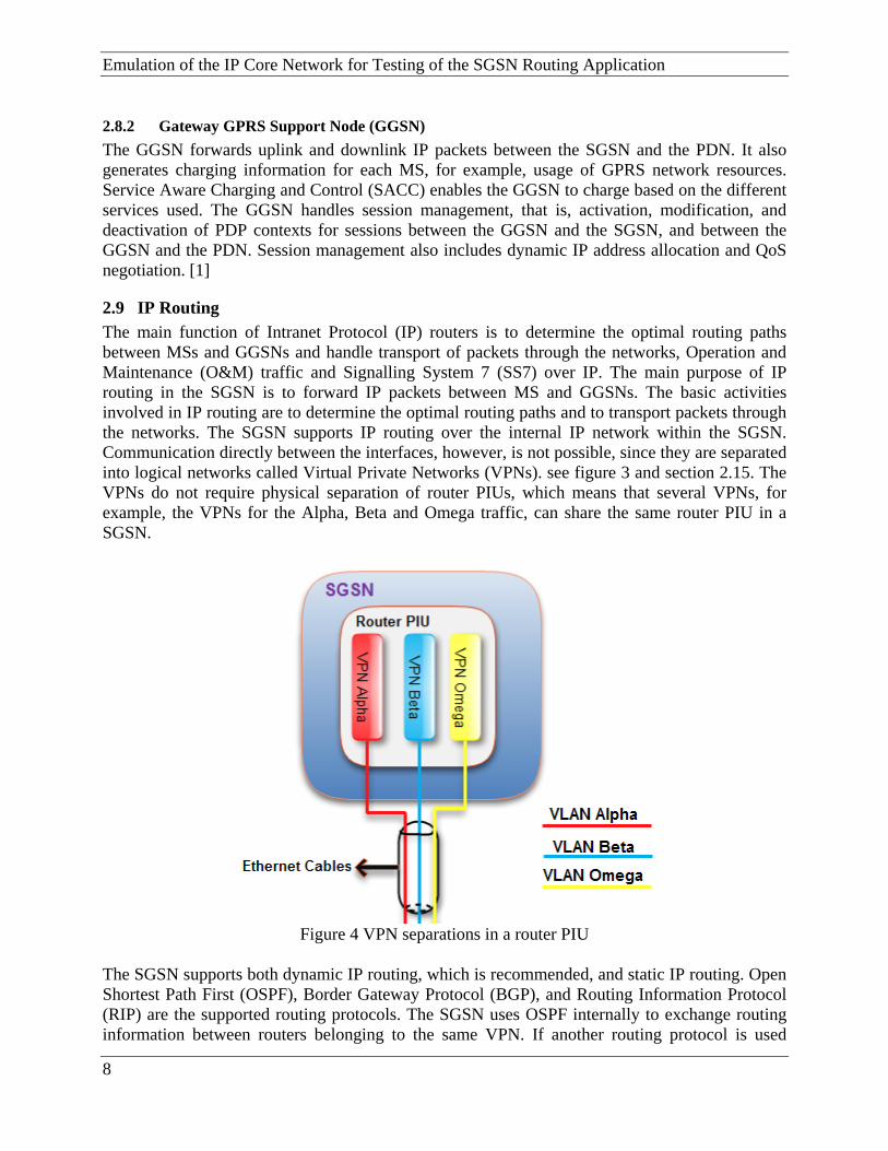
2.9 IP Routing The main function of Intranet Protocol (IP) routers is to determine the optimal routing paths between MSs and GGSNs and handle transport of packets through the networks, Operation and Maintenance (O&M) traffic and Signalling System 7 (SS7) over IP. The main purpose of IP routing in the SGSN is to forward IP packets between MS and GGSNs. The basic activities involved in IP routing are to determine the optimal routing paths and to transport packets through the networks. The SGSN supports IP routing over the internal IP network within the SGSN. Communication directly between the interfaces, however, is not possible, since they are separated into logical networks called Virtual Private Networks (VPNs). see figure 3 and section 2.15. The VPNs do not require physical separation of router PIUs, which means that several VPNs, for example, the VPNs for the Alpha, Beta and Omega traffic, can share the same router PIU in a SGSN.
Figure 4 VPN separations in a router PIU
The SGSN supports both dynamic IP routing, which is recommended, and static IP routing. Open Shortest Path First (OSPF), Border Gateway Protocol (BGP), and Routing Information Protocol (RIP) are the supported routing protocols. The SGSN uses OSPF internally to exchange routing information between routers belonging to the same VPN. If another routing protocol is used
8

GPRS System Overview and Routing Functionality in SGSN externally, the routing information from that routing protocol must be exported to the internal OSPF in order to achieve full redundancy for the SGSN. The Bi-directional Forwarding Detection (BFD) fault detection protocol can be used for monitoring static routes [1 & 11].
2.10 GPRS Backbone Networks GPRS networks are connected through two different IP based backbone networks: [1]
Intra-PLMN backbone network Inter-PLMN backbone network
The intra-PLMN backbone network is the IP network interconnecting GPRS within the same PLMN and connection establish through the Gn interface and always internal routing protocol protocols like OSPF and RIP are running to connecting nodes inside the GPRS system. The inter-PLMN backbone network as it shown on pictures 5 and 6 is the IP network interconnecting GSNs GPRSs intra-PLMN backbone networks via Gp interface in different PLMNs. See figure 5.
Figure 5 GPRS connection thought IP based backbone
9

Emulation of the IP Core Network for Testing of the SGSN Routing Application
Figure 6 GPRS connection between PLMNs
2.11 Packet Routing and Transfer Functions A route is a path which the source node (sender) selects to transfer data packets toward destination node within or between the PLMN(s), the process of selection is based on some policy and rules within and between the PLMN(s).
2.12 Routing Methodology in SGSN The SGSN forwards IP packets according to the destination address in the IP header. Destination IP addresses or subnets are associated with next hop IP addresses. The next hop to which the IP packet should be forwarded can be statically configured, or the information can be retrieved from a dynamic routing protocol. The SGSN supports both dynamic routing and static routing. Since the SGSN uses OSPF internally, any other routing protocol used externally must be exported to OSPF in order to attain redundancy.
10

GPRS System Overview and Routing Functionality in SGSN
Figure 7 Logical Overview of the Routing in SGSN
2.13 Routing Protocols The following dynamic routing protocols are supported by the SGSN Routing Application:
• Open Shortest Path First version 2 (OSPFv2) • Border Gateway Protocol version 4 (BGPv4) • Routing Information Protocol version 2 (RIPv2)
Dynamic routing protocols are used by the SGSN for two primary reasons. Firstly, the IP service addresses are announced to all routing neighbors or peers for each VPN, by exporting the IP address. Secondly, for traffic leaving the SGSN, the SGSN learns routes to other nodes or destinations in the network from its routing neighbors or peers. It is not recommended to configure the external routers to export a large number of IP routes to the SGSN, since this creates unnecessarily large forwarding tables.
2.13.1 Open Shortest Path First version 2 (OSPFv2) OSPF is a link-state routing protocol which interconnects an autonomous system of routers exchanging information. Consequently, if a routing protocol other than OSPF is used externally, exportation rules for the propagation of routes between the internal OSPF and the external protocol must be specified. Since OSPF is an Interior Gateway Protocol (IGP), it is used within an autonomous system. OSPF routers are grouped based on the function they perform in the routing domain:
Internal Routers Backbone Routers Area Border Router Autonomous System boundary Routers
A link-state routing protocol uses link states to describe paths to routers. Every OSPF router in an area in the autonomous system has an identical database, describing the topology of the area or
11

Emulation of the IP Core Network for Testing of the SGSN Routing Application autonomous system. By using this database, each router generates its own open shortest path tree with itself as root, and the routing table is calculated based on that tree. All routers must know the complete architecture before they can construct or verify their respective tree. Adjacent routers maintain synchronized routing tables through Link State Advertisement (LSA) messages. Routing information learned from an external interface, over BGP, for example, appear as branches in the OSPF tree structure. OSPF also supports the configuration of costs (or metrics) to rank the paths to a known router. The cost is just a value to give the routes different priority. The Shortest Path First (SPF) algorithm is used to calculate the best routes to a destination. Consequently, OSPF does not necessarily function as its name implies—open shortest path first. Instead, OSPF routes messages over the path with the lowest cost—open cheapest path first. If the distance and the cost are equal for some routes, the traffic can be equally distributed. During configuration of the OSPF Transport IP address for a point-to-point connection to a remote node, the remote IP address of the interface must be used, that is, the IP address of a PIU in a remote node. During configuration of the OSPF Transport IP address for any other connection to a remote node, the local IP address of the logical interface must be used, that is, the Transport IP address of a router in a VPN in the SGSN. Because of low traffic overhead, fast coverage, larger network metric, area based topology, route summaries, supporting complex address structures and authentication fetcher of OSPF motivates the choice of this routing protocol as the SGSN internal routing protocol. [6, 11 & 44]
2.13.2 Border Gateway Protocol version 4 (BGPv4) The configuration of BGP in the SGSN distinguishes between Internal BGP (IBGP) and External BGP (EBGP). IBGP is used between BGP speakers within the same autonomous system. EBGP is an inter-autonomous system routing protocol that exchanges network reachability information with other EBGP systems. If EBGP is used for routing to another external network, it means that the SGSN network (for example, Gn) is seen as an autonomous system by that network. BGP is transported over the Transport Control Protocol (TCP), and port 179 is used for the connection. A router using BGP establishes TCP connections to its peers and transmits routing information upon detection of a change. BGP does not use any protocol-based mechanism to determine if peers are alive and reachable. Instead, messages, such as keep alive messages, are exchanged between the peers. Configuration of an EBGP session requires the remote autonomous system number. In addition, when using EBGP, a Multi-Exit Discriminator (MED) metric can be configured. It is used as priority parameter to discriminate between multiple exit points to a neighboring autonomous system. The MED metric can be distributed to other BGP routers in the same autonomous system, but never to BGP routers in neighboring autonomous systems. The BGP routing exportation rules must be configured to enable the exportation of BGP sessions into the OSPF database. When running BGP, the SGSN should not be used as a transit router. Consequently, it should not be used as a multi-homed Border Gateway when running EBGP. [4, 11& 44]
2.13.3 Routing Information Protocol version 2 (RIPv2) One of the most widely used interior gateway protocols is the Routing Information Protocol (RIP). RIP is an implementation of a distance-vector algorithm. RIP classifies routers as active and passive. Active routers advertise their routes (reachability information) to others; passive
12
GPRS System Overview and Routing Functionality in SGSN
13
routers listen and update their routes based on advertisements, but do not advertise. Typically, routers run RIP in active mode, while hosts use passive mode. [7, 11 & 44]
2.13.4 Bi-directional Forwarding Detection (BFD) The BFD protocol may be used to monitor any IP addresses. The current SGSN implementation does not, however, support the combined use of BFD and dynamic routing protocols, that is, BFD cannot be used while running OSPF to detect link failures, switch failures, or router failures, faster than the OSPF Hello mechanism. [11]
2.13.5 Static Routing The static statements define the static routes used by SGSN routing application. A single static statement can specify any number of routes. The static statements occur after protocol statements and before control statements in routing application files. Each number containing any number of static route definitions may be specified. These routes can be overridden by routes with better preference values. [11]
2.14 Implementation Structure of the Routing Application in SGSN IP routing functionality, IP forwarding, IP routing protocols and IP connectivity is provided by the routing application in a SGSN node, to provide IP connectivity to GSN IP Services/Application. Execution of the application is controlled by a Root; IP forwarding is performed by an IP stack and a Forwarding Engine (FE), which is dynamically maintained by a Connectivity Daemon (ConnD); IP routing protocols are run by a routing daemon (GateD). All configuration data is provided from the Object Manager through an XML-based API (Resource Object View). Statistics counters are reported to Performance Monitoring (PM), (outside the scope of this thesis). Figure 8 shows the involved components including relevant parts of other delivery packages. All components within the dashed frame are part of application delivery routing package. [36 & 45]

Emulation of the IP Core Network for Testing of the SGSN Routing Application
Figure 8 Module interaction diagram for the Routing Application (VxWorks)
2.14.1 Root The root is responsible for declaration, distribution and execution of the routing application.
2.14.2 Gateway Daemon (GateD) Routing protocols software which is implemented dynamic IP routing protocols, RIP, OSPF and BGP.
2.14.3 Connectivity Daemon Responsibilities for IP forwarding are:
1. Receive and realize configuration data for IP networks. 2. Receive and realize IP configuration data for application IP interfaces. 3. Receive IP configuration data for external IP interfaces (ATM and Ethernet). 4. Receive IP configuration data for IP tunnels (IPSec and GRE). 5. Set up IP connectivity between the application and the external interfaces. Also redundant
forwarding paths should be established. 6. Start, stop and reconfiguration of routing application. 7. Receive and realize configuration data for routing application. 8. Establish routing entries, ARP entries and status of IP interfaces with OBM. 9. Authorization and retrieval of IP, ICMP statistics counters and Interface. 10. To provide information about which IP addresses/interfaces to use for different services. 11. To set up the autofilter (TCP and UDP port filter).
14

GPRS System Overview and Routing Functionality in SGSN
12. Check connectivity with next hops of static routes, which were configured, by using the BFD protocol.
2.14.4 Forwarding Engine FE distributes IP forwarding between router PIUs and application performance monitoring(PM) by caring out instantiated forwarding tables, which support flow-based load-sharing between equal-cost FE routes and variable length IP net masks.
2.15 Network Separation For improving security, capacity, and Quality of Service (QoS) the SGSN traffic is divided into Virtual Private Networks (VPNs). Each VPN corresponds to a logical IP network. VPNs do not require the physical separation of router PIUs; thus, these VPNs can share one or more router PIUs and the corresponding physical interfaces. All VPNs build up on external network, a number of routers with external interfaces, separate routing tables and a number of application PIUs that execute the services which are connected to the VPN. A number of VPNs are using Virtual Local Area Network (VLAN) over Ethernet or ATM, Permanent Virtual Circuits (PVCs) and share the physical interfaces on a router PIU [29, 31 & 9]
Figure 9 Examples of the SGSN VPNs
Each VPN uses separate paths through the SGSN. A path between a router and the application PIUs executing the services connected to the VPN is illustrated with a separately colour line in the figure above.
2.16 Router Plug-In Unit (Router PIU) Each VPN consists of an external network, a set of routers with external interfaces, a set of application PIUs executing the services connected to the VPN, and separate routing tables. Several VPNs can share the physical interfaces on a router PIU by using Virtual Local Area Network (VLAN) over Ethernet or Asynchronous Transfer Mode (ATM) Permanent Virtual
15
Emulation of the IP Core Network for Testing of the SGSN Routing Application Circuits (PVCs). Several types of PIUs are holds in SGSN. Identification of the magazine is established on the Power and Ethernet Boards (PEBs) in the magazine control by all PIUs. A mismatch between the settings in the two PEBs in the magazine generates an alarm. In addition, each PIU handles hardware alarms which, for example, can be raised for excessive temperatures or voltages, or for a power drop-out of one of the redundant branches.
2.17 Node Controller Board (NCB) The active Node Controller Board (NCB) provides central functions, such as disk storage, O&M interfaces, and SGSN supervision. A second PIU serves as a standby by providing a passive NCB replicating all configuration data. If the active NCB fails, or needs replacement, the passive NCB takes over operation.
16
Emulated Core Network Scenarios by Dynamips
3 Emulated Core Network Scenarios by Dynamips
3.1 Introduction The goal in this chapter is to explore the Dynamips created emulation environment as a means or tool to setup different kinds of IP core network scenarios aimed to test the functionality of the routing application in SGSN. In order to verify the emulation ability provided by use of Dynamips, different simulated environments closely resembling the core network on GPRS are considered, studied and then emulated using this tool. To make the results valid it is checked that the routing application of SGSN is meeting the functional and technical requirements in CLI documentation (Ericsson internal technical documents), or not.
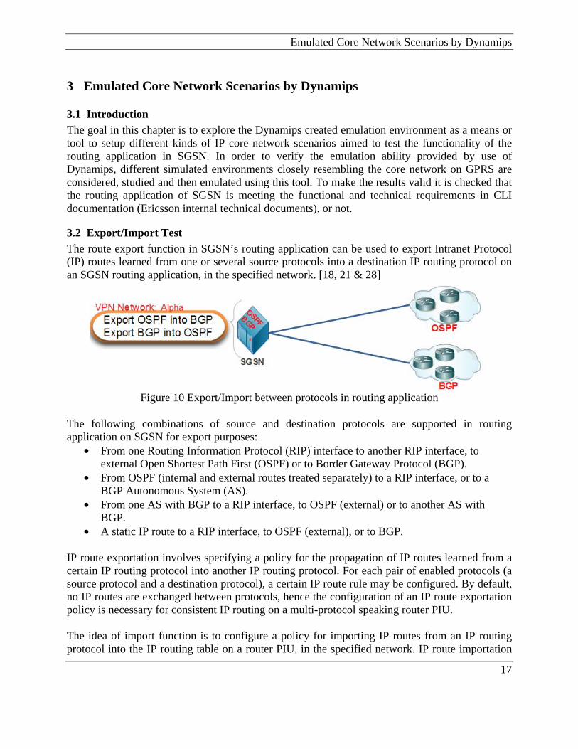
3.2 Export/Import Test The route export function in SGSN’s routing application can be used to export Intranet Protocol (IP) routes learned from one or several source protocols into a destination IP routing protocol on an SGSN routing application, in the specified network. [18, 21 & 28]
Figure 10 Export/Import between protocols in routing application
The following combinations of source and destination protocols are supported in routing application on SGSN for export purposes:
• From one Routing Information Protocol (RIP) interface to another RIP interface, to external Open Shortest Path First (OSPF) or to Border Gateway Protocol (BGP).
• From OSPF (internal and external routes treated separately) to a RIP interface, or to a BGP Autonomous System (AS).
• From one AS with BGP to a RIP interface, to OSPF (external) or to another AS with BGP.
• A static IP route to a RIP interface, to OSPF (external), or to BGP. IP route exportation involves specifying a policy for the propagation of IP routes learned from a certain IP routing protocol into another IP routing protocol. For each pair of enabled protocols (a source protocol and a destination protocol), a certain IP route rule may be configured. By default, no IP routes are exchanged between protocols, hence the configuration of an IP route exportation policy is necessary for consistent IP routing on a multi-protocol speaking router PIU. The idea of import function is to configure a policy for importing IP routes from an IP routing protocol into the IP routing table on a router PIU, in the specified network. IP route importation
17

Emulation of the IP Core Network for Testing of the SGSN Routing Application involves specifying a policy for the inclusion of IP routes learned from an IP routing protocol into the local IP routing table. For each enabled protocol, a certain IP route policy may be configured. By default, all IP routes are imported into the local IP routing table, hence an IP route importation policy provides the ability to restrict the importation of certain IP routes.
3.2.1 Exporting from RIP to OSPF protocol and vice versa Objective The goal with this test setup was to emulate the core network by Dynamips to verify export characteristics of RIP protocol into the OSPF in SGSN routing application, and vice versa. Most OSPF networks also use RIP to communicate with hosts, or to communicate with portions of the Intranetwork that do not use OSPF. SGSN routing application supports both the RIP and OSPF protocols and provides a way to exchange routing information between RIP and OSPF networks. Setup To emulate the IP core network the test requires the setting up of two virtual networks with Dynamips. One of these emulated networks on Dynamips is configured with OSPF protocol to represent the OSPF network topology and routes, while the other emulated network is configured with RIP routing protocol to advertise RIP network topology and routes.
18

Emulated Core Network Scenarios by Dynamips
Figure 11 Hardware setup for Exporting from RIP to OSPF protocol, and vice-versa
Here, in this scenario for testing the redundancy characteristic of routing application at the same time with export characteristics, two router PIUs in SGSN is used. If one of the router PIU fails, traffic is automatically redirected to the other router PIU associated with the same VPNs as the failing PIU. Methodology SGSN:
1. Create and configure VPN network “Beta” on each router PIU in SGSN 2. Configure IP network and subnet for “Beta” VPN network. 3. Configure Ethernet port for “Beta” VPN network 4. Configure IP packet filtering for ethernet ports. 5. Configure a Ethernet VLAN and assign IP interface for Ethernet VLAN 6. Configure routing protocols
a. OSPF: Configure OSPF Configure an OSPF area
19

Emulation of the IP Core Network for Testing of the SGSN Routing Application
Configure an OSPF interface b. RIP:
Create RIP on interface. 7. Configure route exportation
a. Configure route exportation Define the destination protocol to exporting router information Define the source protocol
b. Configure Route Policy Create a route policy Create a route rule
c. Configure route importation Configure the destination for the export information
Emulated IP Core Network by Dynamips and SGSN: A- OSPF: The OSPF virtual network is a complex OSPF environment. It is configured with a multiarea OSPF operation, interarea summarization, and external route summarization. Also, OSPF routing are optimize, which creates the need to design and configure multiarea OSPF. To reduce routing table entries, it was necessary to implement interarea route summarization throughout the Intranetwork. And on router Sanjose1 the network area 1 advertises this summery route to area 0. Also On the router Singapore, it configured with external routes to redistribute routes from Auckland into the OSPF autonomous system. For this purpose Auckland connection simulated by configuring a static route in Singapore. B- RIP: The RIP virtual network is a simple network which includes three routers and all this three routers are configured with the RIP routing protocol. C- SGSN The SGSN is configured with a VPN “Beta”, and this network was created on stack 3 in each one of the routing boards (2.5 and 1.12). Each router board was configured with OSPF and RIP protocols to interact with OSPF and RIP networks in virtual IP core network. OSPF routes from core networks are configured to enter into the SGSN through the VLAN 703, and RIP routes from core networks enter into the SGSN through VLAN 702.
20

Emulated Core Network Scenarios by Dynamips
PIU 2.5 PIU 2.5
Figure 12 Configurations of Router PIUs in SGSN Result After running the emulated routers by Dynamips, expected result was to see that routes from OSPF network export into RIP network and routes from RIP network export into OSPF network. But, by studying the results, routes did not export completely, and the reason was the implementation of export characteristics of routing application in SGSN. For more information about the routing table of each router on each network (OSPF and RIP) and routing table of each router PIU in SGSN, refer to Appendix A, Part 1. Configuration Because of the large amount of configuration in emulated networks and SGSN routing application, only commands configuration relative to exporting routes from RIP into OSPF protocol, and vice versa, only on router PIU 2.5, are given here. Exporting OSPF to RIP gsh create_route_export_destination -edn 2.5_ospf_to_rip -edp rip -dip 10.80.240.12 -eqp 2.5 -nw beta gsh create_route_export_source -edn 2.5_ospf_to_rip -esn ripRoutes -esp ospf -rp 2.5_exportospfTorip_beta gsh create_route_policy -rp 2.5_exportospfTorip_beta gsh create_route_rule -rp 2.5_exportospfTorip_beta -rr 1 -ip 0.0.0.0 -mask 0.0.0.0 -rule accept Exporting RIP to OSPF gsh create_route_export_destination -edn 2.5_rip_to_ospf -edp ospfase1 -eqp 2.5 -nw beta
21

Emulation of the IP Core Network for Testing of the SGSN Routing Application gsh create_route_export_source -edn 2.5_rip_to_ospf -esn ripRoutes -esp rip -sip 10.80.240.12 -rp 2.5_exportRipToOspf_beta gsh create_route_policy -rp 2.5_exportRipToOspf_beta gsh create_route_rule -rp 2.5_exportRipToOspf_beta -rr 1 -ip 0.0.0.0 -mask 0.0.0.0 -rule accept
3.2.2 Exporting from iBGP/eBGP to OSPF protocol and vice versa The goal with this test setup was to emulate the core network by Dynamips to verify the export characteristics of eBGP/iBGP protocol into the OSPF in SGSN routing application, and vice versa. Setup To emulate the IP core network, the test required the setting up of two virtual networks on dynamics. One of these emulated virtual networks on Dynamips is configured with OSPF to represent the OSPF network topology and routes, while another network with BGP routing protocol to advertise iBGP and eBGP network topology and routes.
Figure 13 Hardware setup for exporting from iBGP/eBGP to OSPF protocol and vice versa
22

Emulated Core Network Scenarios by Dynamips
23
Methodology A. SGSN:
1. Create and configure VPN network “Beta” on each router PIU in SGSN 2. Configure IP network and subnet for “Beta” VPN network. 3. Configure Ethernet port for “Beta” VPN network 4. Configure IP packet filtering for ethernet ports. 5. Configure a Ethernet VLAN and assign IP interface for Ethernet VLAN 6. Configure routing protocols
a. OSPF: Configure OSPF Configure an OSPF area Configure an OSPF interface
b. BGP Configure iBGP/eBGP Configure local Autonomous System (AS) for iBGP test purpose Configure external AS for eBGP test purpose Create BGP Peer for eBGP
7. Configure route exportation a. Configure route exportation
Define the destination protocol to exporting router information Define the source protocol
b. Configure route policy Create a route policy Create a route rule
c. Configure route importation Configure the destination for the export information
Emulated IP Core Network by Dynamips: A- OSPF: The OSPF virtual network is a complex OSPF environment. It is configured with a multiarea OSPF operation, interarea summarization, and external route summarization. Also, OSPF routing are optimize, which creates the need to design and configure multiarea OSPF. To reduce routing table entries, it was necessary to implement interarea route summarization throughout the Intranetwork. And on router Sanjose1 the network area 1 advertises this summery route to area 0. Also On the router Singapore, it configured with external routes to redistribute routes from Auckland into the OSPF autonomous system. For this purpose Auckland connection simulated by configuring a static route in Singapore. B- BGP: The BGP virtual networks configure both iBGP and eBGP. In this virtual network, then BGP runs on Frankfort and Hamburg externally with Bonn, AS 200. iBGP ran internally between Frankfort and Hamburg. Once router Bonn and SGSN are configure in a same AS to test iBGP characteristic of routing application, later that SGSN and router Bonn are configure in two separate AS to test eBGP characteristic of routing application on SGSN. C- SGSN The SGSN is configured with a VPN “Beta”, and this network is created on stack 3 in each one of the routing boards (2.5 and 1.12). Each router board is configured with OSPF and BGP protocol

Emulation of the IP Core Network for Testing of the SGSN Routing Application to interact with OSPF and BGP networks in virtual IP core network. OSPF routes from simulated IP core network, configured to enter into the SGSN through the VLAN 703 and BGP routes from IP core network enter into the SGSN through VLAN 702.
PIU 2.5 PIU 1.12
Figure 14 Configurations of Router PIUs in SGSN Result In this scenario, first iBGP is set up to check the redistributing characteristics of routes between BGP and OSPF protocols in SGSN routing application. The result was not as expected to be. Because exported routes from BGP protocol into the OSPF protocol did not show all routes on BGP network. OSPF protocol did not export any routes from OSPF network into iBGP protocol in BGP simulated network. In the second step, eBGP is set up between SGSN and BGP network on Dynamips. After running all routers in Dynamips, some or routes from each network did not export into another one. For more information about the result on routing table of each router in core network, refer to Appendix A, Part 2. In practice, exporting BGP to OSPF in GPRS system, or any other data network, is not a good idea, because one the problems with exporting BGP route to any IGP is that the massive size of the BGP tables may overwhelm the memory and CPU capacity of IGP routes on SGSN or the routers. Exporting in the other direction (IGP to BGP) should be done very carefully, because it is probably that sometimes we will not want all our IGP routes with eBGP neighbors. If individual routes flap up and down, that will increase memory and CPU usage on BGP routes and on eBGP peer. A flapping in the BGP routes can also make the IGP unstable and IGP will always be in the continuous state of recalculation. Configuration
24

Emulated Core Network Scenarios by Dynamips
25
Because of the large amount of configuration in emulated networks and SGSN routing application, only configuration relative to exporting routes from iBGP/eBGP into OSPF protocol and vice versa only on router PIU 2.5 are given here. Exporting OSPF to BGP gsh create_route_export_destination -edn 2.5_ospf_to_bgp -edp bgp -das 500 -eqp 2.5 -nw beta gsh create_route_export_source -edn 2.5_ospf_to_bgp -esn ospfRoutes -esp ospf -sas NULL -sip NULL -rp 2.5_exportOspfToBgp_beta gsh create_route_policy -rp 2.5_exportOspfToBgp_beta gsh create_route_rule -rp 2.5_exportOspfToBgp_beta -rr 1 -ip 0.0.0.0 -mask 0.0.0.0 -rule accept Exporting BGP to OSPF gsh create_route_export_destination -edn 2.5_bgp_to_ospf -edp ospfase1 -eqp 2.5 -nw beta gsh create_route_export_source -edn 2.5_bgp_to_ospf -esn bgpRoutes -esp bgp -sas 200 -rp 2.5_exportBgpToOspf_beta gsh create_route_policy -rp 2.5_exportBgpToOspf_beta gsh create_route_rule -rp 2.5_exportBgpToOspf_beta -rr 1 -ip 0.0.0.0 -mask 0.0.0.0 -rule accept
3.3 Route Capacity Test The goal with this test is to emulate the core network by Dynamips to verify and ensure the ability of routing application on SGSN to handle large quantities of core network’s routes. With the capacity test, we could determine the number of routes that SGSN routing application can contain at a single time. [11 & 28] Following is a list of the main capacity test objectives for SGSN routing application:
• Test the SGSN routing application to its maximum core network route capability • Test the SGSN routing application to its maximum core network link state advertisement
(LSAs) number for OSPF, BGP and RIP protocols • Overload the GPRS IP core network route element to point of failure to determine weak
design on routing application • Verify the system stability over extended periods of time with high and changing
subscriber volumes • Find memory leaks on SGSN routing application • Generate worst-case routing scenarios with Dynamips to simulate IP core network, for
example, mix routing protocols scenarios, IP packet filtering and security and configuring import/export characteristics of routers
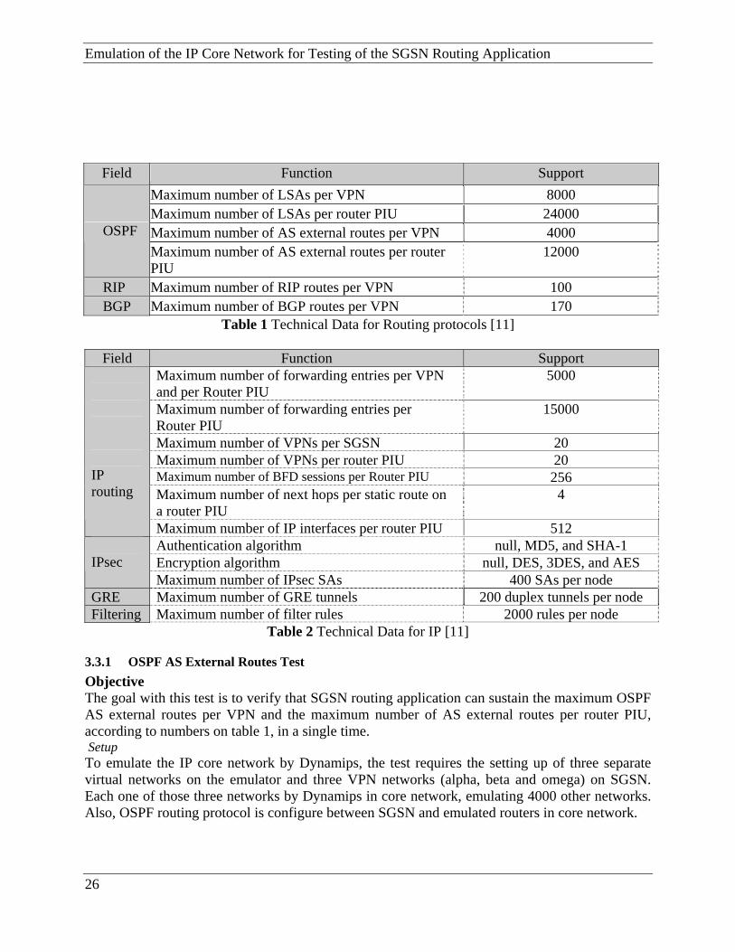
The IP routing forwarding table on routing application on SGSN may be populated with routes learnt from OSPF or RIP neighbors, BGP peers, or with routes configured as static routes on IP core network. The maximum size of the forwarding table (table 1 and 2) on SGSN routing application represents a limit on the sum of all of these routes, and cannot be exceeded even though none of the individual route limits have been exceeded.
Test cases in this part should verify and meet all items in table 1 and table 2 to verify that routing application can handle the maximum amount of LSAs, routes, forwarding entries, IPsec, GRE and filter rules in a single time.
Emulation of the IP Core Network for Testing of the SGSN Routing Application
Field Function Support
Maximum number of LSAs per VPN 8000 Maximum number of LSAs per router PIU 24000 Maximum number of AS external routes per VPN 4000 OSPF Maximum number of AS external routes per router PIU
12000
RIP Maximum number of RIP routes per VPN 100 BGP Maximum number of BGP routes per VPN 170
Table 1 Technical Data for Routing protocols [11]
Field Function Support Maximum number of forwarding entries per VPN and per Router PIU
5000
Maximum number of forwarding entries per Router PIU
15000
Maximum number of VPNs per SGSN 20 Maximum number of VPNs per router PIU 20 Maximum number of BFD sessions per Router PIU 256 Maximum number of next hops per static route on a router PIU
4
IP routing
Maximum number of IP interfaces per router PIU 512 Authentication algorithm null, MD5, and SHA-1 Encryption algorithm null, DES, 3DES, and AES
IPsec
Maximum number of IPsec SAs 400 SAs per node GRE Maximum number of GRE tunnels 200 duplex tunnels per node Filtering Maximum number of filter rules 2000 rules per node
Table 2 Technical Data for IP [11]
3.3.1 OSPF AS External Routes Test Objective The goal with this test is to verify that SGSN routing application can sustain the maximum OSPF AS external routes per VPN and the maximum number of AS external routes per router PIU, according to numbers on table 1, in a single time. Setup To emulate the IP core network by Dynamips, the test requires the setting up of three separate virtual networks on the emulator and three VPN networks (alpha, beta and omega) on SGSN. Each one of those three networks by Dynamips in core network, emulating 4000 other networks. Also, OSPF routing protocol is configure between SGSN and emulated routers in core network.
26
Emulated Core Network Scenarios by Dynamips
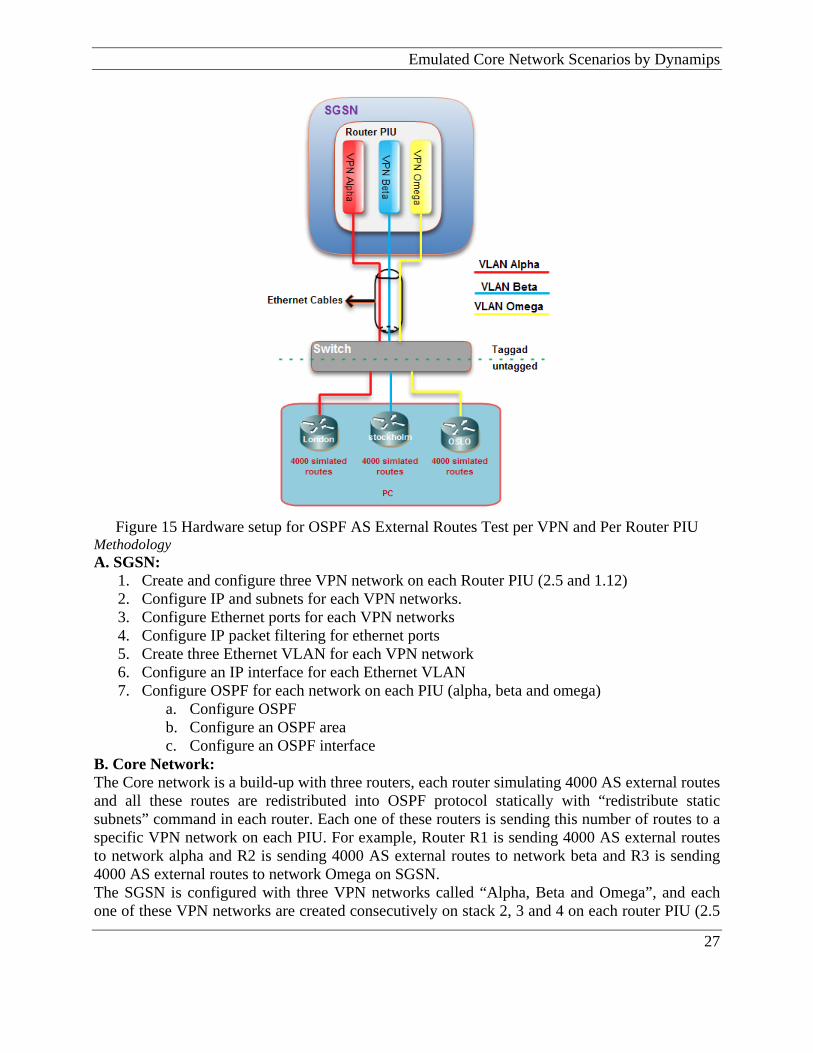
Figure 15 Hardware setup for OSPF AS External Routes Test per VPN and Per Router PIU
Methodology A. SGSN:
1. Create and configure three VPN network on each Router PIU (2.5 and 1.12) 2. Configure IP and subnets for each VPN networks. 3. Configure Ethernet ports for each VPN networks 4. Configure IP packet filtering for ethernet ports 5. Create three Ethernet VLAN for each VPN network 6. Configure an IP interface for each Ethernet VLAN 7. Configure OSPF for each network on each PIU (alpha, beta and omega)
a. Configure OSPF b. Configure an OSPF area c. Configure an OSPF interface
B. Core Network: The Core network is a build-up with three routers, each router simulating 4000 AS external routes and all these routes are redistributed into OSPF protocol statically with “redistribute static subnets” command in each router. Each one of these routers is sending this number of routes to a specific VPN network on each PIU. For example, Router R1 is sending 4000 AS external routes to network alpha and R2 is sending 4000 AS external routes to network beta and R3 is sending 4000 AS external routes to network Omega on SGSN. The SGSN is configured with three VPN networks called “Alpha, Beta and Omega”, and each one of these VPN networks are created consecutively on stack 2, 3 and 4 on each router PIU (2.5
27

Emulation of the IP Core Network for Testing of the SGSN Routing Application & 1.12) in SGSN. Each one of these VPN networks are configured with OSPF protocol to communicate with routers in Dynamips. All 4000 AS external routes from each emulated network on IP core network imports into the SGSN through three spread VLANs. 4000 AS external routes from router Oslo imports into the network Omega through VLAN 703, another 4000 AS external routes from router Stockholm imports into the network Beta through VLAN 702 and 4000 AS external routes from router London imports into the network Alpha through VLAN 701 as well.
Figure 16 Stacks per VPN in router PIU 2.5
Result When the test is completed and the tolerance has been exceeded, the result in figure 14 shows that all 4000 OSPF AS external routes per VPN network and 12000 per router PIU entered into the SGSN successfully.
28

Emulated Core Network Scenarios by Dynamips
Figure 17 OSPF AS external routes per VPN and per router PIU
Configuration Because of the large amount of configuration in emulated networks and SGSN routing application, only configuration relative to network VPN alpha on router PIU 2.5 are given. Configuration for the other two VPN networks is almost identical similar to alpha network. Alpha VPN network configuration:
gsh create_ip_network -nw alpha gsh create_ip_network_subnet -nw alpha -ip 10.77.128.1 -mask 255.255.255.255 gsh create_ospf -eqp 2.5 -nw alpha gsh create_ospf_area -eqp 2.5 -nw alpha -area 0.0.0.0 gsh create_ospf_interface -eqp 2.5 -nw alpha -area 0.0.0.0 -ifn ETH_2_5_0_701 -type bcast -prio 1 -retr 5 gsh create_eth_vlan -eqp 2.5 -ep 0 -vid 701 gsh create_inbound_pf_policy -ifp ETH_2_5_0_701 gsh create_inbound_pf_rule -ifp ETH_2_5_0_701 -fr 1 -r permit -p ip -d NULL -dm NULL -sip 0.0.0.0 -sipm 0.0.0.0 -dip 0.0.0.0 -dipm 0.0.0.0 -p p 0 -ppq gt -ipo true -sp 0 -spq gt -dp 0 -dpq gt -tf NULL -tfm NULL -it 0 -itq gt -sd NULL -lt false gsh create_ip_interface -ifn ETH_2_5_0_701 -ip 10.80.236.12 -mask 255.255.255.0 -rip NULL -eqp 2.5 -ep 0 -vid 701 -ifp ETH_2_5_0_701 -ofp ETH_2_5_0_701 -nw alpha -hello 10 -dead 40 -cost 1 -aualg n ull -auid NULL -aukey NULL gsh create_outbound_pf_policy -ofp ETH_2_5_0_701 gsh create_outbound_pf_rule -ofp ETH_2_5_0_701 -fr 1 -r permit -p ip -d NULL -dm NULL -sip 0.0.0.0 -sipm 0.0.0.0 -dip 0.0.0.0 -dipm 0.0.0.0 -pp 0 -ppq gt -ipo true -sp 0 -spq gt -dp 0 -dpq gt -tf NULL -tfm NULL -it 0 -itq gt -sd NULL -lt false gsh create_router_instance -eqp 2.5 -nw alpha -ip 10.80.236.12 -sn NULL -sc NULL -sl NULL
29
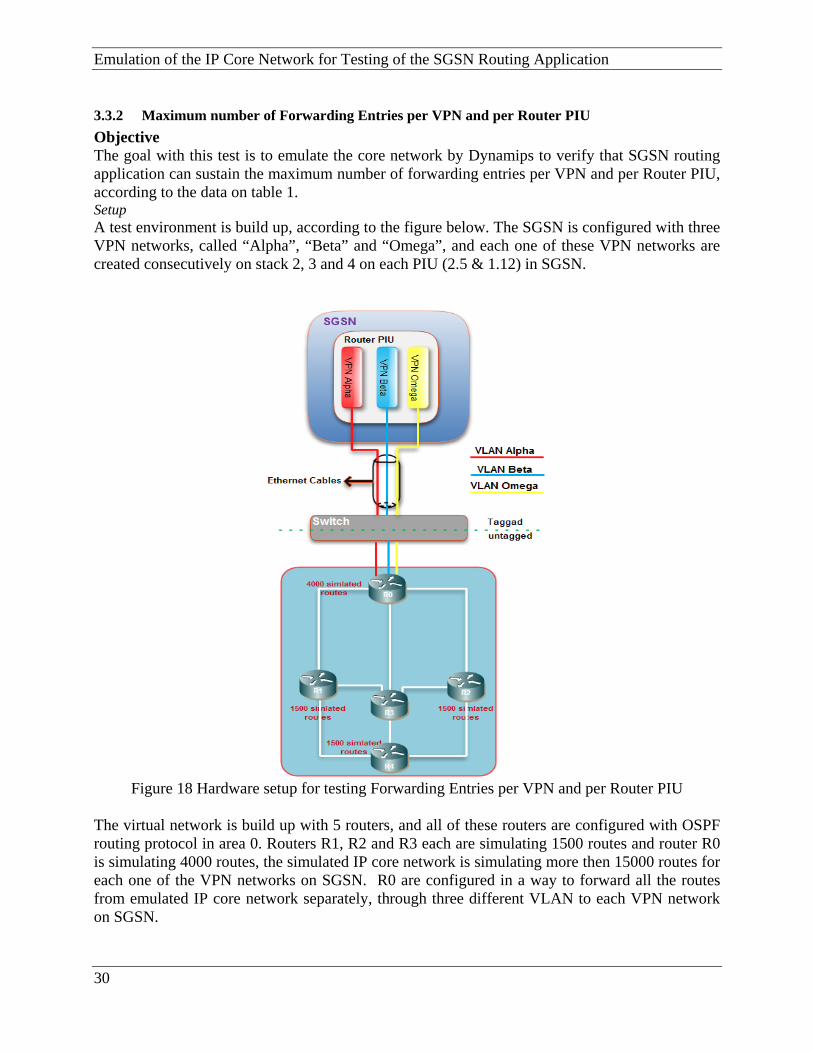
Emulation of the IP Core Network for Testing of the SGSN Routing Application 3.3.2 Maximum number of Forwarding Entries per VPN and per Router PIU Objective The goal with this test is to emulate the core network by Dynamips to verify that SGSN routing application can sustain the maximum number of forwarding entries per VPN and per Router PIU, according to the data on table 1. Setup A test environment is build up, according to the figure below. The SGSN is configured with three VPN networks, called “Alpha”, “Beta” and “Omega”, and each one of these VPN networks are created consecutively on stack 2, 3 and 4 on each PIU (2.5 & 1.12) in SGSN.
Figure 18 Hardware setup for testing Forwarding Entries per VPN and per Router PIU
The virtual network is build up with 5 routers, and all of these routers are configured with OSPF routing protocol in area 0. Routers R1, R2 and R3 each are simulating 1500 routes and router R0 is simulating 4000 routes, the simulated IP core network is simulating more then 15000 routes for each one of the VPN networks on SGSN. R0 are configured in a way to forward all the routes from emulated IP core network separately, through three different VLAN to each VPN network on SGSN.
30
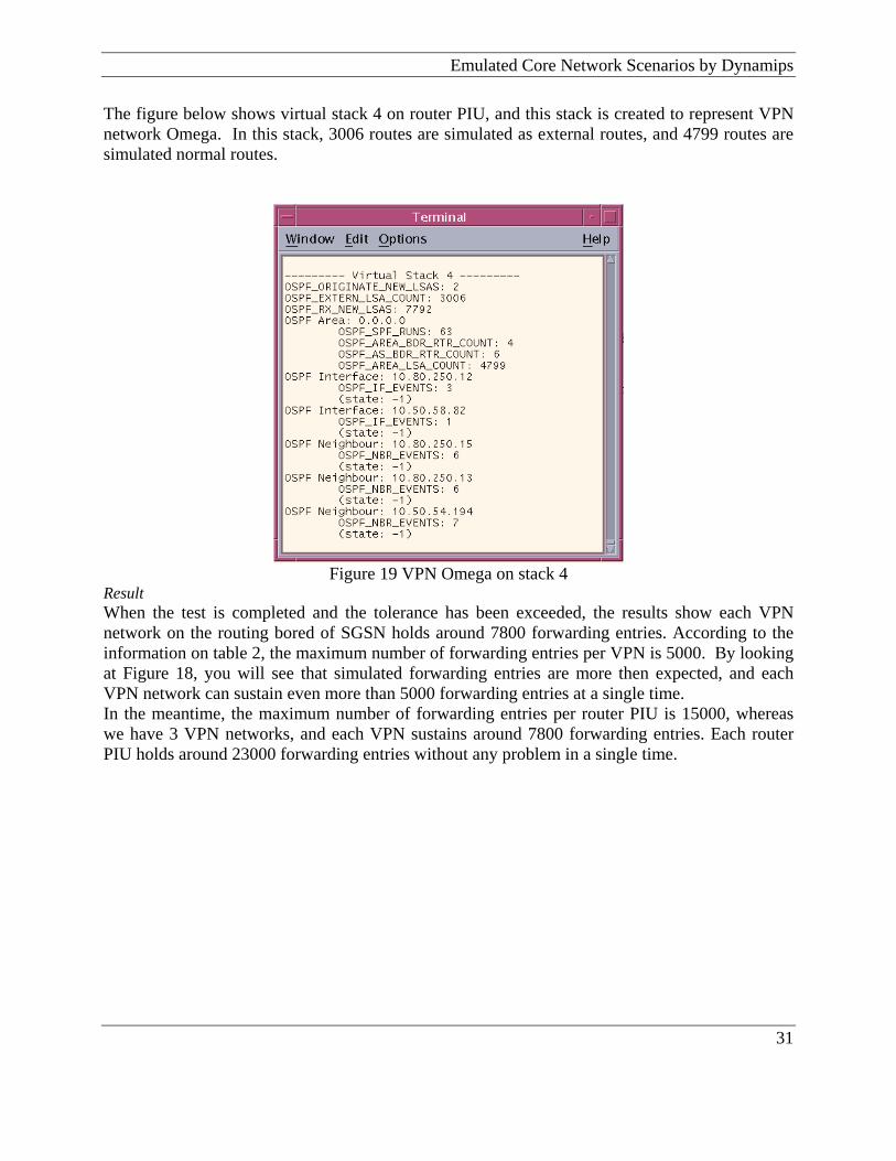
Emulated Core Network Scenarios by Dynamips The figure below shows virtual stack 4 on router PIU, and this stack is created to represent VPN network Omega. In this stack, 3006 routes are simulated as external routes, and 4799 routes are simulated normal routes.
Figure 19 VPN Omega on stack 4
Result When the test is completed and the tolerance has been exceeded, the results show each VPN network on the routing bored of SGSN holds around 7800 forwarding entries. According to the information on table 2, the maximum number of forwarding entries per VPN is 5000. By looking at Figure 18, you will see that simulated forwarding entries are more then expected, and each VPN network can sustain even more than 5000 forwarding entries at a single time. In the meantime, the maximum number of forwarding entries per router PIU is 15000, whereas we have 3 VPN networks, and each VPN sustains around 7800 forwarding entries. Each router PIU holds around 23000 forwarding entries without any problem in a single time.
31

Emulation of the IP Core Network for Testing of the SGSN Routing Application
Figure 20 forwarding entries per VPN and per PIU
Configuration Configurations of VPNs on SGSN are similar to the configuration on section 3.3.14.
3.3.3 Maximum number of RIP, BGP and OSPF routes per VPN Objective The goal with this test is to emulate the core network to verify that SGSN routing application can sustain the maximum number of RIP, BGP and OSPF routes with the combination of these three routing protocols in a VPN network on SGSN. Setup To emulate the IP core network by Dynamips, the test requires to setting up of virtual networks which are able to emulate the combination of BGP, RIP and OSPF for a specific VPN (Beta) at SGSN, in a single time, with the maximum capacity of each routing protocol, as defined by engineers.
32

Emulated Core Network Scenarios by Dynamips
Figure 21 Hardware setup for testing maximum RIP, BGP and OSPF routes per VPN
Methodology A. SGSN
1. Create and configure VPN network “Beta” on each router PIU (2.5 and 1.12) 2. Configure IP network and subnet for “Beta” VPN network. 3. Configure Ethernet port for “Beta” VPN network 4. Configure IP packet filtering for ethernet ports. 5. Configure the three Ethernet VLAN 6. Configure IP interface for each Ethernet VLAN 7. Configure routing protocols for each router PIU
a) OSPF: i. Configure OSPF
ii. Configure an OSPF area iii. Configure an OSPF interface
b) BGP:
i. Configure BGP and specify a local AS number ii. Configure a BGP peer and add the remote IP address of a BGP peer
c) RIP: i. Create and active RIP on an interface.
B. Core Network Emulator
33

Emulation of the IP Core Network for Testing of the SGSN Routing Application IP core network is build up with four routers. Router R1, R3 and R4 emulating, consecutively, RIP, BGP and OSPF routers. Router R0 forwards the routes learned from other three routers on the core network and sends those routes into the VPN Beta on SGSN through three VLANs (701, 702 and 703). Each one of these VLANs carries different routing protocol traffic for routing application on SGSN from emulated IP core network. A- SGSN: The SGSN is configured with a VPN network called “Beta”, and this VPN network is created on stack 3 in SGSN. The RIP, BGP and OSPF traffic, handled by SGSN, and with different IP networks, to improve security, capacity, and Quality of Service. Ttherefore three IP network and subnets creates and configures for IP core network traffic to enter via separate IP networks into the VPN network (Beta). Result The primary goal of this test is to emulate 100 RIP routes, 170 BGP routes, and 4000 OSPF routes, all together in a single time for each VPN network in SGSN. After running the routers on emulated IP core network, by looking at Figure 21, that shows forwarding table value at network beta on SGSN is 4283, that means VPN network beta can sustain combination with maximum number of RIP (100), BGP (170) and OSPF (4000) at a single time.
Figure 22 forwarding entries per VPN and per PIU
Configuration Configurations of VPNs on SGSN are similar to the configuration on section 3.3.15.
34
Suggested Routing Application Verification Tests by Dynamips
35
4 Suggested Routing Application Verification Tests by Dynamips Scope: The goal of this chapter is to study different types of verification tests which Dynamips can utilize when emulating test environments to improve the SGSN routing application. The test scenarios in this chapter are
4.1 OSPF Tests The test suggested here include conformance, functional, and performance tests studied for Design and Test engineers at Ericsson to testing functionality and characteristics of OSPF protocol in routing application on SGSN, and provide a baseline for achieving network quality. [39]
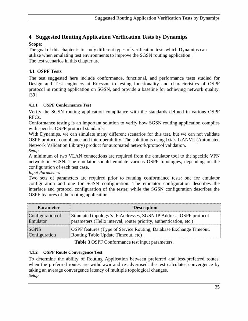
4.1.1 OSPF Conformance Test Verify the SGSN routing application compliance with the standards defined in various OSPF RFCs. Conformance testing is an important solution to verify how SGSN routing application complies with specific OSPF protocol standards. With Dynamips, we can simulate many different scenarios for this test, but we can not validate OSPF protocol compliance and interoperability. The solution is using Ixia's IxANVL (Automated Network Validation Library) product for automated network/protocol validation. Setup A minimum of two VLAN connections are required from the emulator tool to the specific VPN network in SGSN. The emulator should emulate various OSPF topologies, depending on the configuration of each test case. Input Parameters Two sets of parameters are required prior to running conformance tests: one for emulator configuration and one for SGSN configuration. The emulator configuration describes the interface and protocol configuration of the tester, while the SGSN configuration describes the OSPF features of the routing application.
Parameter Description
Configuration of Emulator
Simulated topology’s IP Addresses, SGSN IP Address, OSPF protocol parameters (Hello interval, router priority, authentication, etc.)
SGNS Configuration
OSPF features (Type of Service Routing, Database Exchange Timeout, Routing Table Update Timeout, etc)
Table 3 OSPF Conformance test input parameters.
4.1.2 OSPF Route Convergence Test To determine the ability of Routing Application between preferred and less-preferred routes, when the preferred routes are withdrawn and re-advertised, the test calculates convergence by taking an average convergence latency of multiple topological changes. Setup
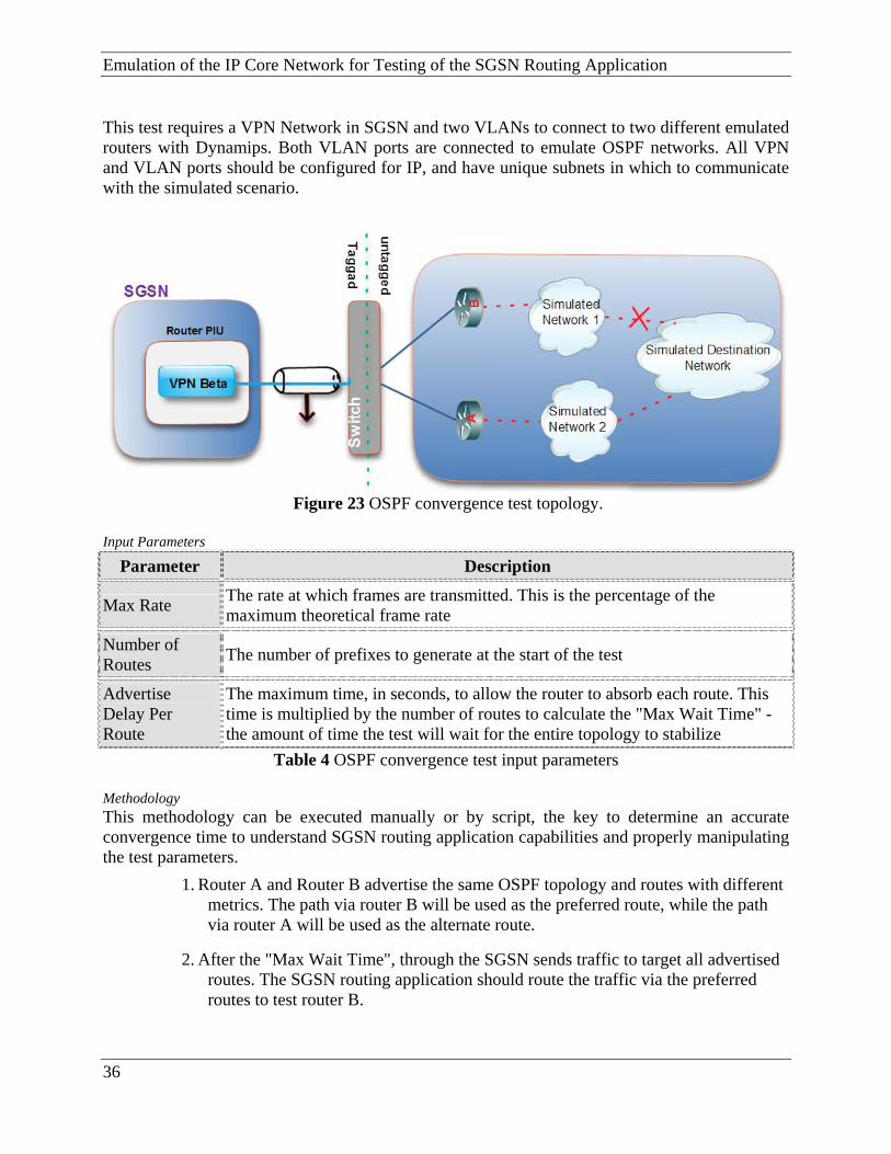
Emulation of the IP Core Network for Testing of the SGSN Routing Application This test requires a VPN Network in SGSN and two VLANs to connect to two different emulated routers with Dynamips. Both VLAN ports are connected to emulate OSPF networks. All VPN and VLAN ports should be configured for IP, and have unique subnets in which to communicate with the simulated scenario.
Figure 23 OSPF convergence test topology.
Input Parameters
Parameter Description
Max Rate The rate at which frames are transmitted. This is the percentage of the maximum theoretical frame rate
Number of Routes The number of prefixes to generate at the start of the test
Advertise Delay Per Route
The maximum time, in seconds, to allow the router to absorb each route. This time is multiplied by the number of routes to calculate the "Max Wait Time" - the amount of time the test will wait for the entire topology to stabilize
Table 4 OSPF convergence test input parameters
Methodology This methodology can be executed manually or by script, the key to determine an accurate convergence time to understand SGSN routing application capabilities and properly manipulating the test parameters.
1. Router A and Router B advertise the same OSPF topology and routes with different metrics. The path via router B will be used as the preferred route, while the path via router A will be used as the alternate route.
2. After the "Max Wait Time", through the SGSN sends traffic to target all advertised routes. The SGSN routing application should route the traffic via the preferred routes to test router B.
36

Suggested Routing Application Verification Tests by Dynamips
3. Routes are withdrawn from router B (the preferred path). Traffic should re-route to arrive through router A (the alternate path).
4. Measure the timestamp T1 of the last packet targeting a specific route delivered on the preferred path. Measure the timestamp T2 of the first packet targeting the same route arriving via the alternate path.
5. Calculate the convergence time for one specific route = T2 - T1.
6. Repeat step 4 and 5 to obtain convergence time for all withdrawn routes. Calculate average convergence for all.
4.1.3 OSPF Topology Scalability Test The purpose with this test is to build an OSPF topology and test the SGSN's routing application capability to learn intra-area LSAs. A given number of LSAs should generate and traffic sent to all routes advertised to verify. Setup The test requires at least two VLAN ports and one VPN in SGSN as shown in Figure 24. The emulator must be able to generate OSPF LSAs.
Figure 24 OSPF topology scalability test.
Inputs Parameters
Parameter Description
Traffic rate Rate at which traffic is sent to the destination routes
Number of routes The number of routes is dependent on the number of emulated routers.
Number of routers
The number of emulated routers dictates the number of routes, depending on whether the configuration is broadcast or point-to-point
Table 5 OSPF topology scalability test input parameters Methodology
1. Configure at least two VLAN ports - one to transmit and one to receive for OSPF.
37
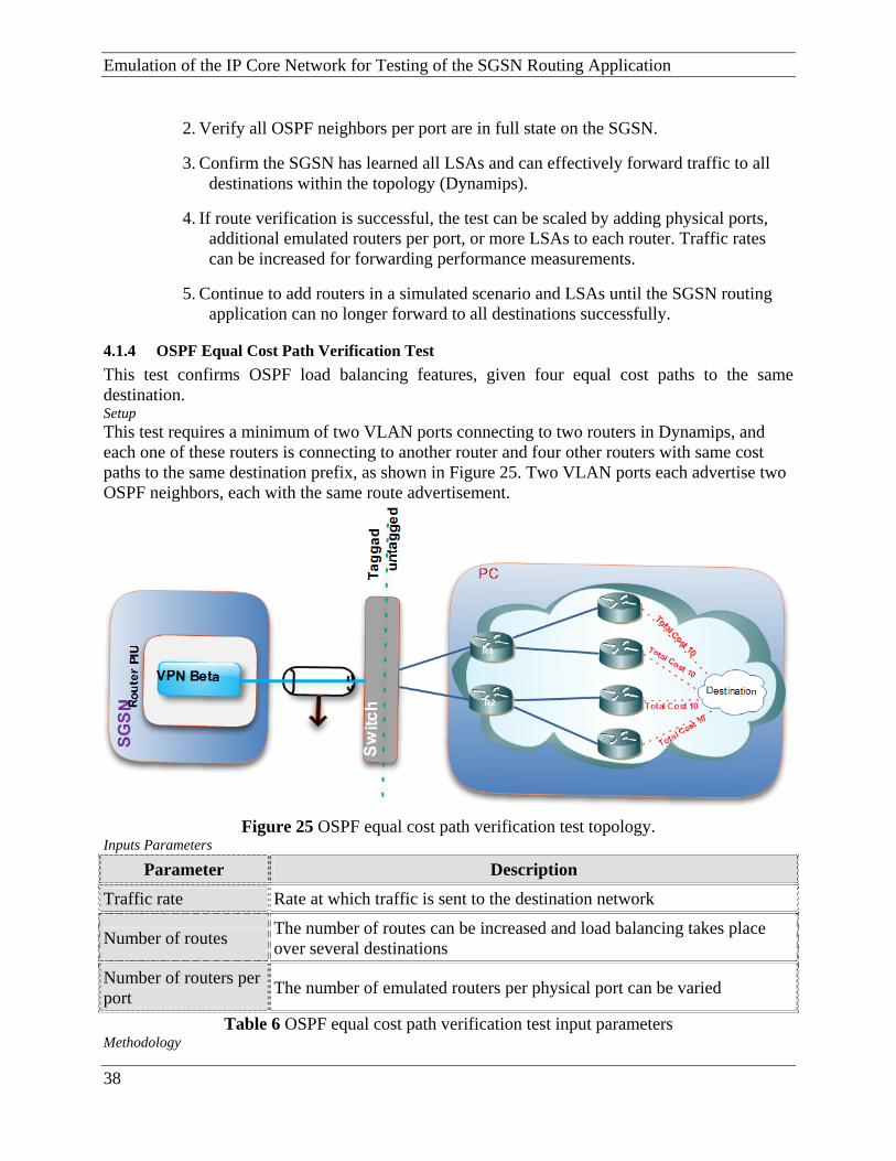
Emulation of the IP Core Network for Testing of the SGSN Routing Application
2. Verify all OSPF neighbors per port are in full state on the SGSN.
3. Confirm the SGSN has learned all LSAs and can effectively forward traffic to all destinations within the topology (Dynamips).
4. If route verification is successful, the test can be scaled by adding physical ports, additional emulated routers per port, or more LSAs to each router. Traffic rates can be increased for forwarding performance measurements.
5. Continue to add routers in a simulated scenario and LSAs until the SGSN routing application can no longer forward to all destinations successfully.
4.1.4 OSPF Equal Cost Path Verification Test This test confirms OSPF load balancing features, given four equal cost paths to the same destination. Setup This test requires a minimum of two VLAN ports connecting to two routers in Dynamips, and each one of these routers is connecting to another router and four other routers with same cost paths to the same destination prefix, as shown in Figure 25. Two VLAN ports each advertise two OSPF neighbors, each with the same route advertisement.
Figure 25 OSPF equal cost path verification test topology.
Inputs Parameters
Parameter Description
Traffic rate Rate at which traffic is sent to the destination network
Number of routes The number of routes can be increased and load balancing takes place over several destinations
Number of routers per port The number of emulated routers per physical port can be varied
Table 6 OSPF equal cost path verification test input parameters Methodology
38
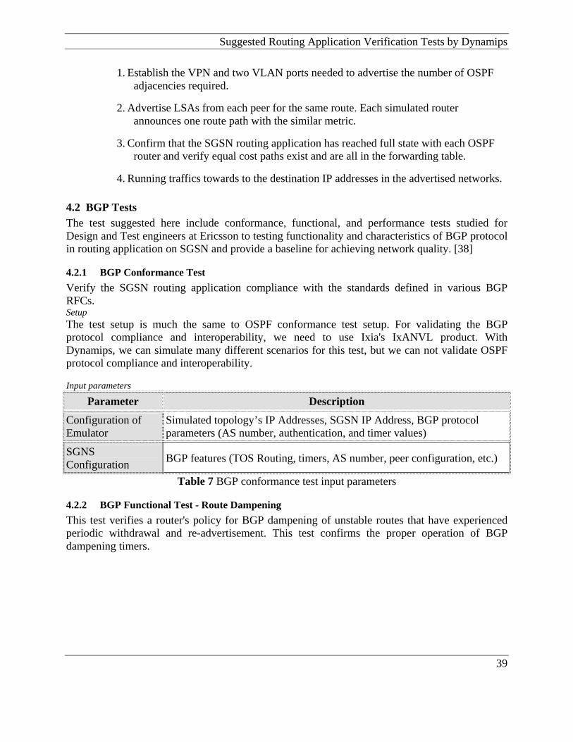
Suggested Routing Application Verification Tests by Dynamips
39
1. Establish the VPN and two VLAN ports needed to advertise the number of OSPF adjacencies required.
2. Advertise LSAs from each peer for the same route. Each simulated router announces one route path with the similar metric.
3. Confirm that the SGSN routing application has reached full state with each OSPF router and verify equal cost paths exist and are all in the forwarding table.
4. Running traffics towards to the destination IP addresses in the advertised networks.
4.2 BGP Tests The test suggested here include conformance, functional, and performance tests studied for Design and Test engineers at Ericsson to testing functionality and characteristics of BGP protocol in routing application on SGSN and provide a baseline for achieving network quality. [38]
4.2.1 BGP Conformance Test Verify the SGSN routing application compliance with the standards defined in various BGP RFCs. Setup The test setup is much the same to OSPF conformance test setup. For validating the BGP protocol compliance and interoperability, we need to use Ixia's IxANVL product. With Dynamips, we can simulate many different scenarios for this test, but we can not validate OSPF protocol compliance and interoperability. Input parameters
Parameter Description
Configuration of Emulator
Simulated topology’s IP Addresses, SGSN IP Address, BGP protocol parameters (AS number, authentication, and timer values)
SGNS Configuration BGP features (TOS Routing, timers, AS number, peer configuration, etc.)
Table 7 BGP conformance test input parameters
4.2.2 BGP Functional Test - Route Dampening This test verifies a router's policy for BGP dampening of unstable routes that have experienced periodic withdrawal and re-advertisement. This test confirms the proper operation of BGP dampening timers.
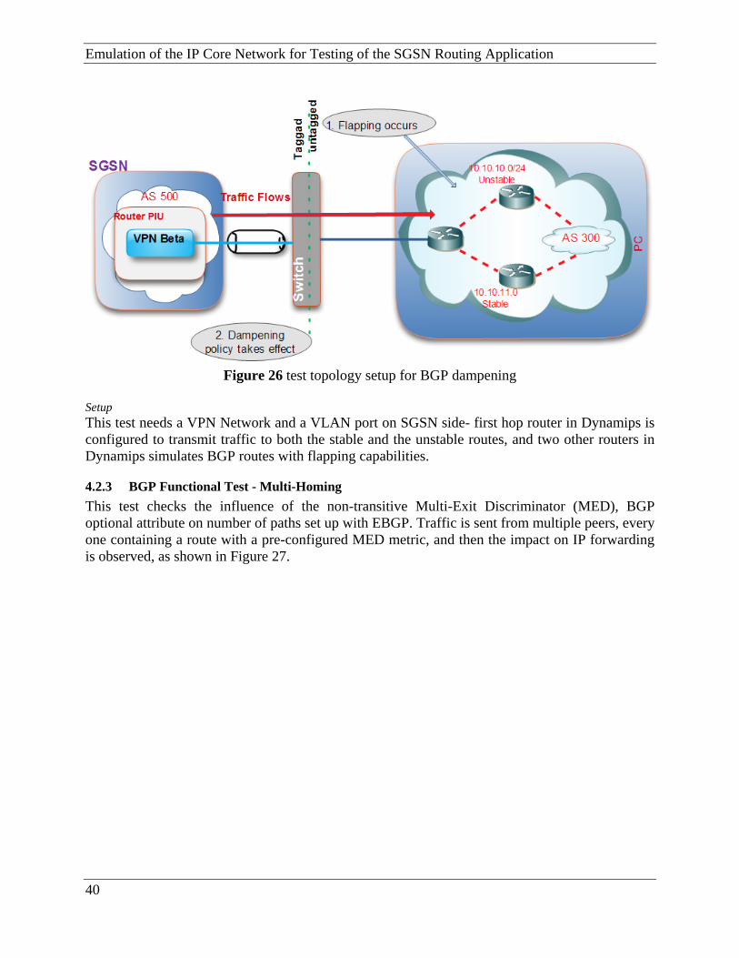
Emulation of the IP Core Network for Testing of the SGSN Routing Application
Figure 26 test topology setup for BGP dampening
Setup This test needs a VPN Network and a VLAN port on SGSN side- first hop router in Dynamips is configured to transmit traffic to both the stable and the unstable routes, and two other routers in Dynamips simulates BGP routes with flapping capabilities.
4.2.3 BGP Functional Test - Multi-Homing This test checks the influence of the non-transitive Multi-Exit Discriminator (MED), BGP optional attribute on number of paths set up with EBGP. Traffic is sent from multiple peers, every one containing a route with a pre-configured MED metric, and then the impact on IP forwarding is observed, as shown in Figure 27.
40
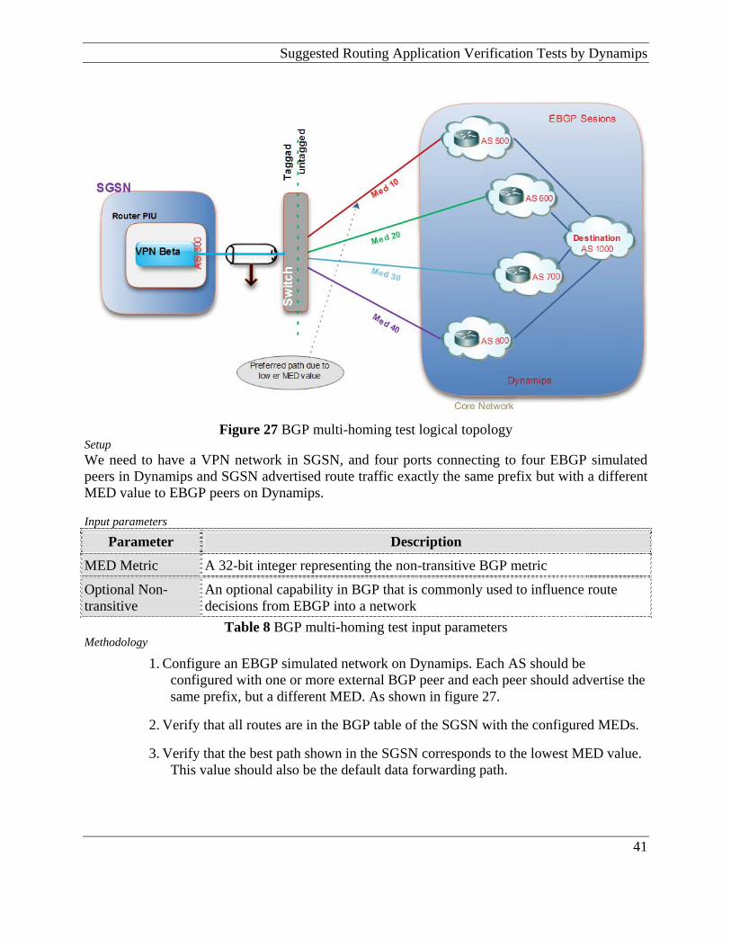
Suggested Routing Application Verification Tests by Dynamips
Figure 27 BGP multi-homing test logical topology
Setup We need to have a VPN network in SGSN, and four ports connecting to four EBGP simulated peers in Dynamips and SGSN advertised route traffic exactly the same prefix but with a different MED value to EBGP peers on Dynamips. Input parameters
Parameter Description
MED Metric A 32-bit integer representing the non-transitive BGP metric
Optional Non-transitive
An optional capability in BGP that is commonly used to influence route decisions from EBGP into a network
Table 8 BGP multi-homing test input parameters Methodology
1. Configure an EBGP simulated network on Dynamips. Each AS should be configured with one or more external BGP peer and each peer should advertise the same prefix, but a different MED. As shown in figure 27.
2. Verify that all routes are in the BGP table of the SGSN with the configured MEDs.
3. Verify that the best path shown in the SGSN corresponds to the lowest MED value. This value should also be the default data forwarding path.
41

Emulation of the IP Core Network for Testing of the SGSN Routing Application 4.2.4 BGP Performance Test - Route Convergence This test checks ability of a SGSN to switch between less-preferred and preferred, routes when the preferred routes are re-advertised and withdrawn. The test verifies and calculates convergence by taking an average convergence latency of number of topological changes. Setup This test uses one VPN network and two VLAN ports connected to two routers in different AS on a simulated network with Dynamips. Dynamips are emulating BGP networks. SGSN should be configured for IP, and have unique subnets to communicate with the different peers on simulated networks.
Figure 28 BGP convergence test topology
Input parameters
Parameter Description
Max Rate The rate at which frames are transmitted
Routes Per Peer The number of route prefixes to generate at the start of the test per peer
Delay Maximum time in seconds the router is allowed to absorb the advertised routes
Advertise Delay Per Route
The maximum time, in seconds, to allow the router to absorb each route
Table 9 BGP convergence test input parameters Methodology
1. SGSN advertise same BGP prefixes through port 1 and port 2 via two difference VLAN, The path via Port 1 is used as the preferred route, while the path via Port 2 is used as the alternate route.
42

Suggested Routing Application Verification Tests by Dynamips
43
2. Waiting after for a while indicated by "Delay" from SGSN side one packet is sent to each port through VLANs. The SGSN should route the traffic via the preferred AS-path via Port 1.
3. Routes are withdrawn from Port 1 (the preferred path). Traffic should re-route to arrive at Port 2 (the alternate path).
4. The number of packets lost or transmitted in the incorrect direction is measured after the routes are withdrawn for each configured route. The packet loss is converted to time.
5. Repeating step 3 and 4 to obtain convergence time results for all withdrawn routes. Calculate the average convergence across all routes.
4.3 RIP Tests The different test cases suggested here contain functional, performance, and conformance tests studied for Design and Test engineers at Ericsson to testing functionality and characteristics of RIP protocol, and prepare a baseline for reaching network quality [40].
4.3.1 RIP Conformance Test The aim of this test is similar to OSPF and BGP conformance test to verify the SGSN routing application compliance with the standards defined in various BGP RFCs. For testing the RIP protocol interoperability and compliance, it is necessary to use Ixia's IxANVL product, because Dynamips let us only to simulate many different scenarios. But we can not validate RIP protocol compliance and interoperability.
4.3.2 RIP IP Summary Address Test The purpose of this test is to verify SGSN routing application operation when performing Summary Addressing within RIPv2. The routing application needs to advertise the summarized local IP address pool on a network, so that the IP addresses can be used for VPN or PPP connections where the mask would be /32.
4.4 Redundancy Testing If one of the IP router PIUs in the SGSN fails, the traffic is automatically redirected to other router PIUs associated with the same VPNs as the failing PIU. Failure of one router PIU can result in a reduced capacity over the interface due to high load on the remaining router PIUs. With each VPN distributed over many router PIUs, though, the capacity decrease is minimized. In the Gn link, redundancy between links and routers outside the SGSN are handled by the routing protocol in use.
Emulation of the IP Core Network for Testing of the SGSN Routing Application
Figure 29 Redundancy topology test
4.5 Security and Tunnelling Test An SGSN supports IPsec in tunnel or transport mode or GRE tunnels, when communicating with other nodes in the network. All routers also support IP packet filtering, which enables filtering of inbound and outbound IP traffic. IPsec (IP Security) is a layer three protocol standards, establishing secure transfer of information over insecure IP networks by encrypting and authenticating of IP packets. IPsec protects paths between a pair of hosts, a pair of Security Gateways or between a Security Gateway and a host. Packet filters on the routers, configured before IPsec, decide which packets are treated with IPsec. Generic Routing Encapsulation (GRE) is a layer 3 protocol providing a simple form of IP tunnelling. Only the GRE tunnel end points are visible. Packet filters on the routers, configured before GRE, decide which packets are treated with GRE.
4.5.1 IPSec and GRE conformance test The purpose of this test is similar to other conformance tests above this report, and the aim is to validate the IPSec and GRE with IETF standards.
44

Suggested Routing Application Verification Tests by Dynamips
45
4.5.2 Tunnel scalability test To settle maximum number of tunnels which SGSN routing application can be set up in a single time.
4.5.3 Tunnel setup rate test To determine the rate at which the SGSN routing application can setup IPSec and GRE tunnels under varying conditions.
4.5.4 Re-key Test To determine the long-term stability of the SGSN routing application with re-keying, and the rate at which the routing application can re-key.
4.5.5 Data Performance Test To determine encryption and decryption performance of the SGSN routing application that the impact of IPSec and GRE on application performance can be assessed
Emulation of the IP Core Network for Testing of the SGSN Routing Application
5 Results In this thesis, a number of deployment scenarios by Dynamips have been presented on Chapter 2, which proves the use of Dynamips for emulating different IP core network scenarios for testing SGSN routing application for different purposes.
5.1 Achievements: As a result of this work is Dynamips could be used to emulate many complicated IP core network scenarios, with many routers to generate huge amounts of route traffic to simulate the real world IP core networks. In general we can use Dynamips for testing following purposes to test Routing Application: Export/Import Testers can implement the different IP core network scenarios by
Dynamips for testing export/Import function. This function in SGSN routing application can be used to export Intranet Protocol (IP) routes learned from one or several source protocols into a destination IP routing protocol on an SGSN routing application, in the specified network.
Scalability, Functional and Performance Tests of routing protocols on Routing application
In this thesis some plans presented which included scalability, functional, and performance tests. Function and systems engineers can use Dynamips for setting up different scenarios for testing OSPF, BGP, RIP, IPsec, GRE, IPv6 protocols, and provide a baseline for achieving network quality.
Testing Route Capacity
Test Engineers at Ericsson can implement different scenarios with Dynamips to determine SGSN routing application to its maximum core network route capability for OSPF, BGP, RIP, IPsec, and GRE protocols.
Security and Tunnelling Test
SGSN supports IPsec and GRE protocols in tunnel or transport mode, Testers and Designers can implements test scenarios for testing IP networks using encryption and authentication of IP packets with IPsec and GRE protocols.
IPV6 Tests
Ericsson started to implement IPv6 on all part of SGSN, as well as routing application. Test and design engineers can use Dynamips to simulate different types of IP core network scenarios on GPRS system to test deploying of IPv6.
5.2 Problems aroused by use of Dynamips By implement the number of test cases and analyzing the use of this method, number of problems aroused during the use of Dynamips.
5.2.1 Traffic Separation per VPN The traffic for each emulated VPN with Dynamips should be completely separate until traffic does not mix with other VPN route traffics.
46

Results
Figure 30 Traffic Separations by VLANs By looking at the figure above, emulated VPN network route traffic on Dynamips should carried separately to/from a specific ethernet adaptor card into the switch. For example, if plan is to setup a scenario to emulatee the maximum number of VPN per SGSN which, according to the table 2 in chapter 3, is 20 VPN, emulator mashie needs to have 20 ethernet adaptor cards in that emulator machine to carry traffic separately to /from each emulated VPN into the switch, as untagged packet frames.
5.2.2 Memory and CPU Consumption problems Another problem that may come up when we are using Dynamips is memory and CPU usage. Simulated IP core network with this emulator can consume a large amount of real and virtual memory on machines on which Dynamips are running. The “ghostios” option is added in Dynamips to address this issue. The “Ghostios” option can significantly reduce the amount of real host RAM needed for labs with multiple routers running the same IOS image. With this feature, instead of each virtual router storing an identical copy of IOS in its virtual RAM, the host will allocate one shared region of memory that they will all utilize. For example, if we are running 10 routers all with the same IOS image, and that image is 60 MB in size, we will save 9*60 = 540 MB of real RAM when running emulated core networks. When a Cisco IOS is running in Dynamips, it consumes up to 100% of machine’s CPU time. This will cause our computer to become slow and will prevent building more complex IP core network scenarios. However, if we use an idlepc value, we can reduce CPU usage dramatically. It puts the IOS into a sleep state when it is not in active use and wakes it up only when it is necessary. The “idlepc” command performs analysis on a running image to determine the most likely points in the code that represent an idle loop in the IOS process. Once applied, Dynamips “sleeps” the virtual router occasionally, when this idle loop is executed. This extremely reduces CPU usage on the station which Dynamips is running, without reducing the virtual router’s capacity to perform real work.
47

Emulation of the IP Core Network for Testing of the SGSN Routing Application 5.2.3 Validating Protocols with RFCs For verifying protocols which are implemented in SGSN routing application compliance with the standards defined in various RFCs, we can only simulate test scenarios by Dynamips, but we can not validate protocol compliance and interoperability. The solution is using Ixia's IxANVL (Automated Network Validation Library) product for automated network/protocol validation.
48

Further Extensions/Work with Dynamips
6 Further Extensions/Work with Dynamips
6.1 Automation of test cases Since the Dynamips is using cisco platform and requires tester have cisco experiences and knowledge. Maybe that would be necessary to find a way to automate execution of generated test cases. For this purpose we need to developing a methodology which to simplify and automate test cases with start and stop the pre configured test cases with everyone who are not familiar with cisco routers. For reaching this goal, first of all realistic test cases (emulated test cases on chapter 3, suggested test cases on chapter 4 and IPV6 test cases in this chapter) should be created with a cisco expert by using Dynamips, later this when number of test scenarios created, those test cases could be store on the computer which Dynamips is running or on VNC servers. And the end generated test cases could be able to start with this automation tool.
6.2 IPv6 Testing The core network will be transformed after IPv6 fully replaces IPv4. Ericsson has started to implement IPv6 on all part of SGSN, as well as routing application. The main goal of this chapter is to show how Dynamips would be able to emulate different types of IP core network scenarios on GPRS system to test IPv6 performance, functional and scalability tests of next generation routing application.
6.2.1 IPv4/IPv6 Forwarding Performance Test The goal by this test is to see and verify how Dynamips can emulate network to create a number of mixed Ipv4 and IPv6 traffics to stress SGSN routing application, to specify the performance of the data plane in forwarding IPv4 and IPv6 traffic.
6.2.2 Tunnelling Functional Test The main objective of this test case should to verify correct encapsulation and decapsulation between IPv6 and IPv4.
6.2.3 Tunnelling Performance Test To determine SGSN’s routing application performance in encapsulating and decapsulating with IPv6 tunnelled traffic.
Figure 31 Tunnel performance test topology for IPv6
49
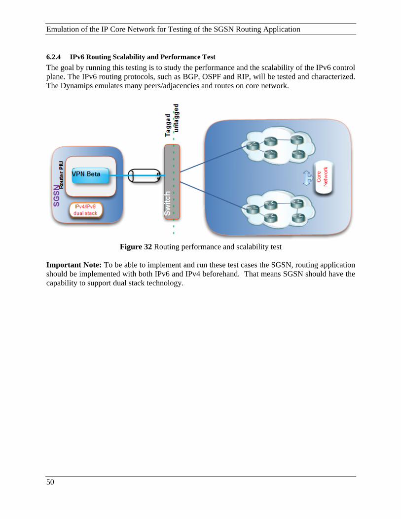
Emulation of the IP Core Network for Testing of the SGSN Routing Application 6.2.4 IPv6 Routing Scalability and Performance Test The goal by running this testing is to study the performance and the scalability of the IPv6 control plane. The IPv6 routing protocols, such as BGP, OSPF and RIP, will be tested and characterized. The Dynamips emulates many peers/adjacencies and routes on core network.
Figure 32 Routing performance and scalability test
Important Note: To be able to implement and run these test cases the SGSN, routing application should be implemented with both IPv6 and IPv4 beforehand. That means SGSN should have the capability to support dual stack technology.
50
Conclusion
51
7 Conclusion The main goal of this thesis was to analyze and verifying the use of Dynamips to emulating IP Core Network of the GPRS system for testing of different functionality of the routing application running in SGSN , instead of building up a physical Core Network with different infrastructure and many routers. A conclusion of this work is that Dynamips could be used to emulate many complicated IP core network scenarios, with many routers to generate huge amounts of data to simulate the real world IP core network. The emulated system fulfils its purpose for testing of the routing application of SGSN regarding different functionality and characteristics. This is done to ensure and verify that SGSN routing application meets its functional and technical requirements, and also helps to find undiscovered errors as well as helps to ensure that the individual components of routing application on SGSN are working correctly. Evaluating the test results for suggested tests on chapter 4 are more complex, and it requires an intelligent system test tool to study and verify the test results and compare it with the RFCs. Dynamips have ability only to emulate the test environments, not verify the test results. Dynamips provides the emulation of Cisco IOSs on your Linux or Windows based computer. Emulation is possible for a long list of PIX firewalls and router platforms. There are a many router simulators on the market, but they are limitation to the commands that the developer chooses to include. Usually always there are some commands or parameters that are not supported when working on a practice scenarios. In these simulators you are only seeing a representation of the output of a simulated router. The accuracy of that representation is only as good as the developer makes it. With Dynamips you are running an actual and real Cisco IOS, so you will see exactly what the IOS produces and will have access to any command or parameter supported by the IOS. In addition, GNS3 is an open source, free program for you to use. However, due to licensing restrictions, you will have to provide your own Cisco IOSs to use with GNS3. Also, GNS3 will provide around 1,000 packets per second throughput in a virtual environment. A normal router will provide a hundred to a thousand times greater throughput. GNS3 does not take the place of a real router, but is meant to be a tool for learning and testing in a lab environment. Using GNS3 in any other way would be considered improper.

Emulation of the IP Core Network for Testing of the SGSN Routing Application
6 References Standards [1] 3GPP TS 23.060 3rd Generation Partnership Project; Technical Specification Group
Services and System Aspects; General Packet Radio Service (GPRS); V6.15.0 (2006-12) [2] 3GPP TS 29.205 V6.1.0 (2006-06) - 3rd Generation Partnership Project; Technical
Specification Group Core Network and Terminals; Application of Q.1900 series to bearer independent Circuit Switched (CS) core network architecture; Stage 3 (Release 6)
[3] 3GPP TS 23.060: "3rd Generation Partnership Project; Technical Specification Group
Services and Systems Aspects; General Packet Radio Service (GPRS); Stage 2 (Release 1999)
[4] A Border Gateway Protocol 4 (BGP-4) IETF RFC1771. [5] Internet Control Message Protocol, IETF RFC792. [6] OSPF Version 2, IETF RFC2328. [7] RIP Version 2, IETF RFC2453. [8] Standard for the transmission of IP datagram over Ethernet Networks, IETF RFC894 [9] Virtual LANs, IEEE 802.1Q, 2000. Ericsson Documents [10] IP-Based Interface Configuration, OPERATION DIRECTIONS, 12/1543-AXB 250 05/8 [11] IP Connectivity and Routing, TECHN PRODUCT DESCR, 13/221 02-AXB 250 05/8 [12] IP Interface (CLI) MANUAL PAGE, 27/190 80-CRA 250 56/1 [13] IP Network (CLI) MANUAL PAGE, 28/190 80-CRA 250 56/1 [14] IP Packet Filtering (CLI) MANUAL PAGE, 30/190 80-CRA 250 56/1 [15] IPsec and Tunneling (CLI) MANUAL PAGE, 130/190 80-CRA 250 56/1. [16] IP Routing - BFD (CLI) MANUAL PAGE, 114/190 80-CRA 250 56/1. [17] IP Routing - BGP (CLI) MANUAL PAGE, 31/190 80-CRA 250 56/1. [18] IP Routing - Export and Import (CLI) MANUAL PAGE, 37/190 80-CRA 250 56/1.
52
Others
53
[19] IP Routing - General (CLI) MANUAL PAGE, 34/190 80-CRA 250 56/1. [20] IP Routing - OSPF (CLI) MANUAL PAGE, 35/190 80-CRA 250 56/1. [21] IP Routing - RIP (CLI) MANUAL PAGE, 36/190 80-CRA 250 56/1. [23] IP Routing - Static Route (CLI) MANUAL PAGE, 38/190 80-CRA 250 56/1. [24] IP Service (CLI) MANUAL PAGE, 131/190 80-CRA 250 561 [25] SGSN 2009A Hardware, TECHN PRODUCT DESCR, 25/221 02-AXB 250 05/8. [26] Ethernet (CLI) MANUAL PAGE, 129/190 80-CRA 250 56/1. [27] Common Interface Configuration, OPERATION DIRECTIONS, 7/1543-AXB 250 05/8. [28] Configuration Management (CLI) MANUAL PAGE, 54/190 80-CRA 250 56/1. [29] IP Interface (CLI) MANUAL PAGE, 27/190 80-CRA 250 56/1 [30] Application Restart (CLI) MANUAL PAGE, 6/190 80-CRA 250 56/1 [31] Ethernet (CLI) MANUAL PAGE, 129/190 80-CRA 250 56/1. [32] Application Configuration (CLI) MANUAL PAGE, 75/190 80-CRA 250 56/1. [33] GGSN R5 Technical Product Description Overview, TECHN PRODUCT DESCR, 1/221
02-AXB 250 10/3 [34] SGSN 2008B Technical Product Description Overview, TECHN PRODUCT DESCR,
8/221 02-AXB 250 05/8 [35] SGSN 2009A Technical Product Description Overview, TECHN PRODUCT DESCR,
26/221 02-AXB 250 05/8. [36] MD Routing - 1551 – COX 901 105 – July 2008
Others [37] Harry Perros, Computer Simulation Techniques, Computer Science Department, NC
State University Raleigh, NC. 2008 [38] BGP Conformance and Performance Testing: Ixia white papers– 2004 [39] OSPF Conformance and Performance Testing Ixia white papers – 2004

Emulation of the IP Core Network for Testing of the SGSN Routing Application [40] RIP Conformance and Performance Testing Ixia white papers – 2005 [41] http://www.Dynamips Date: Sumer 2009 [42] www.gns3.net. – Date: Sumer 2009 [43] www.3gpp.org [44] Cisco Advanced Routing and Switching Sales Specialist � 646-003 [45] Operating GateD - V.9.3.1 - NextHop Technologies, 2002
54

Appendix A
Appendix A Part 1 Routing table of each router on emulator core network and PIU boards on SGSN: Routing table for PIU 1.12:
Routing table for PIU 2.5:
55
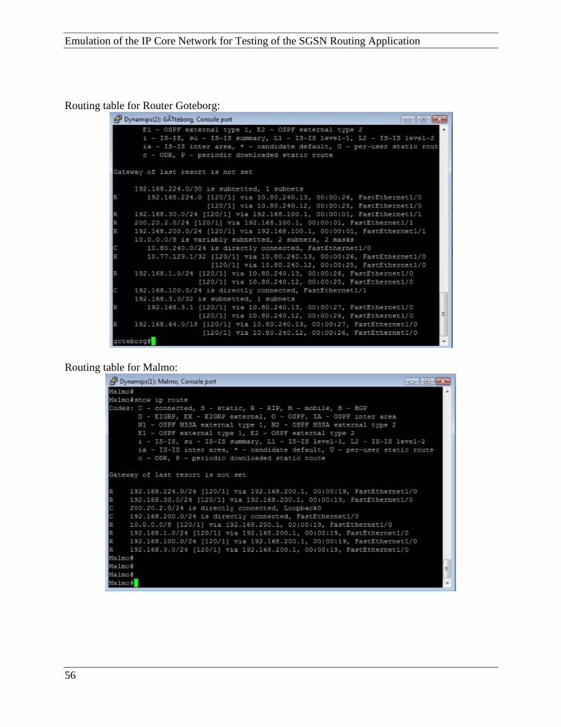
Emulation of the IP Core Network for Testing of the SGSN Routing Application Routing table for Router Goteborg:
Routing table for Malmo:
56
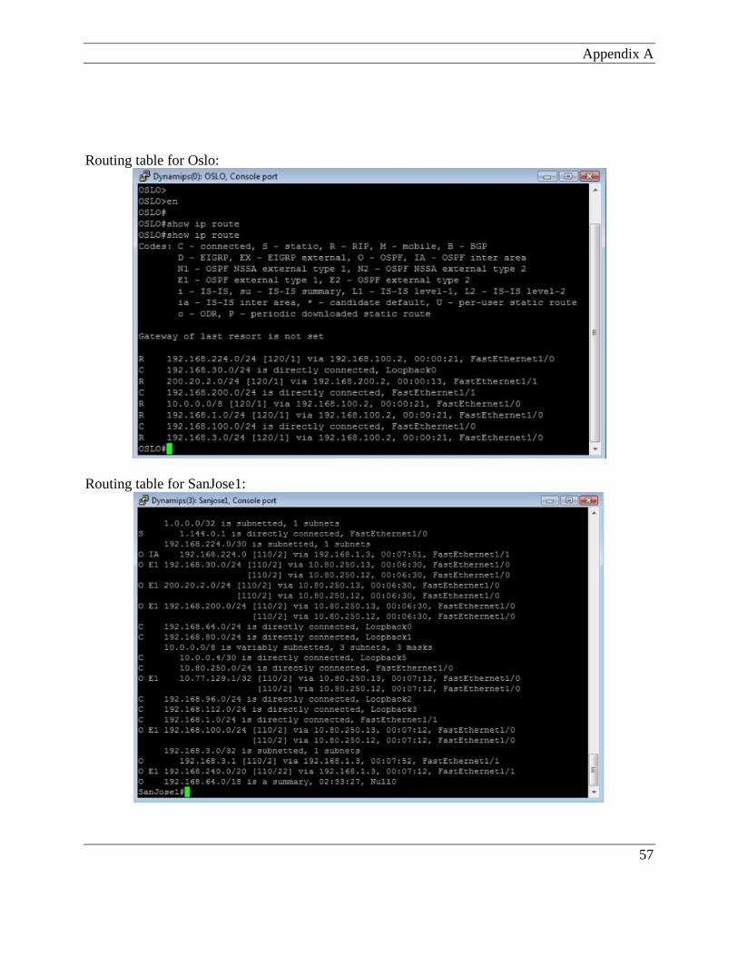
Appendix A Routing table for Oslo:
Routing table for SanJose1:
57
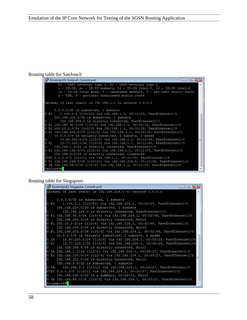
Emulation of the IP Core Network for Testing of the SGSN Routing Application Routing table for SanJose3:
Routing table for Singapore:
58

Appendix A Part 2 Routing table of each router on emulator core network and PIU boards on SGSN:
Figure 12 Routing table on PIU (2.5)
Figure 13 Routing table on PIU (1.12)
59
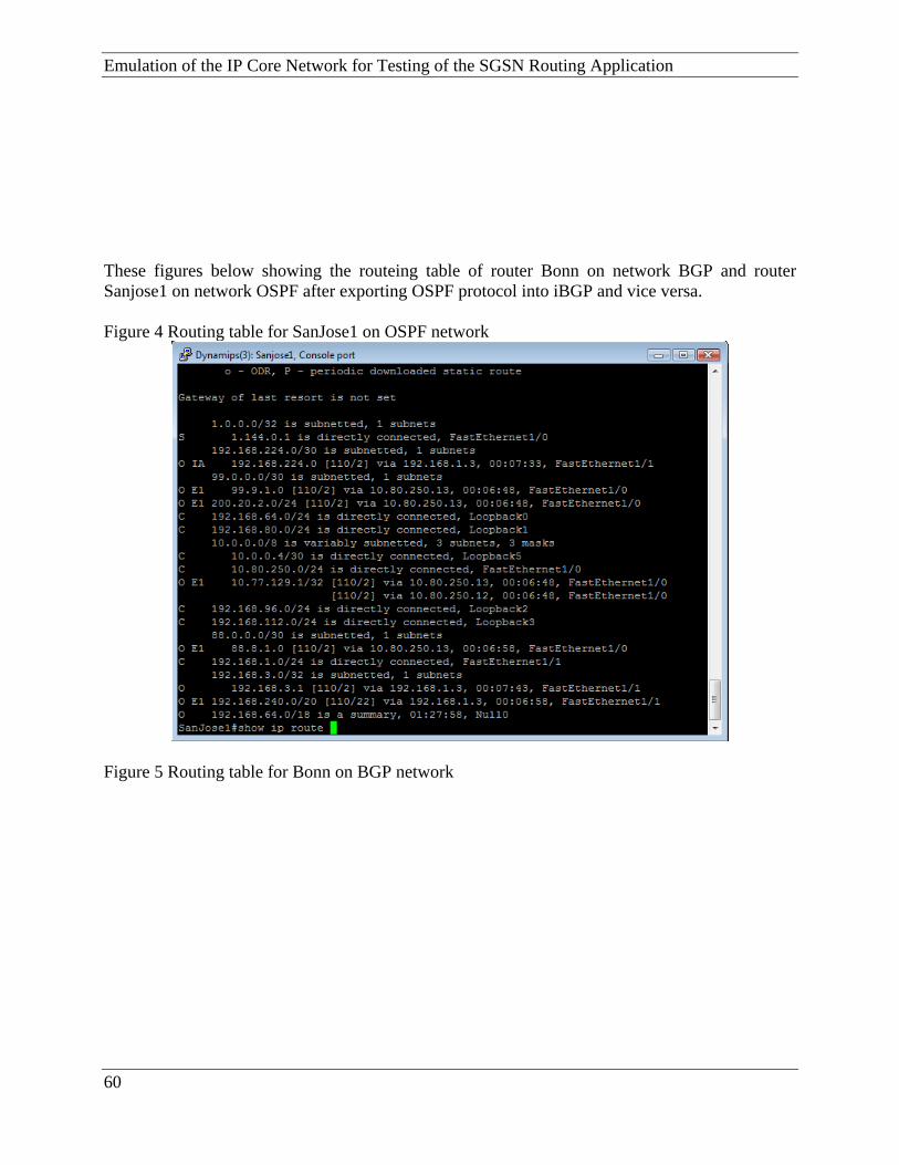
Emulation of the IP Core Network for Testing of the SGSN Routing Application These figures below showing the routeing table of router Bonn on network BGP and router Sanjose1 on network OSPF after exporting OSPF protocol into iBGP and vice versa. Figure 4 Routing table for SanJose1 on OSPF network
Figure 5 Routing table for Bonn on BGP network
60

Appendix A
And figures below showing the routeing table of all routers and PIUs on SGSN and both networks after exporting OSPF protocol into eBGP and vice versa. Figure 6 Routing table for Bonn on BGP network
Figure 7 Routing table for Frankfort on BGP network
61
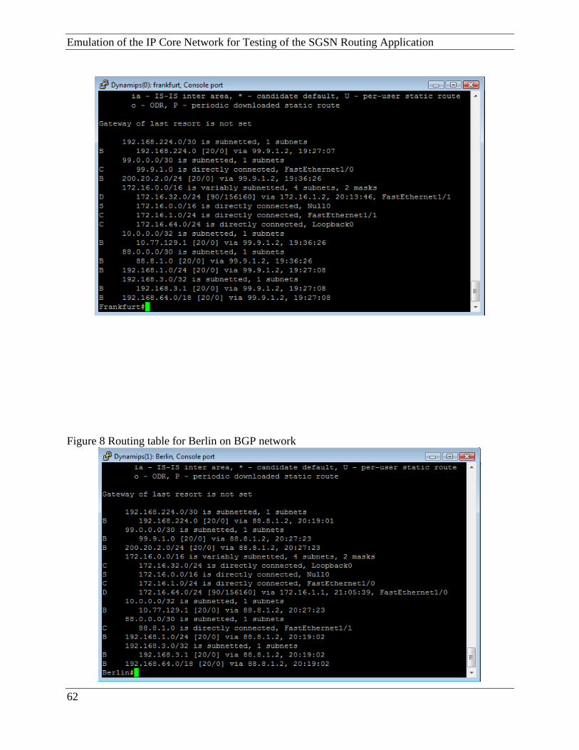
Emulation of the IP Core Network for Testing of the SGSN Routing Application
Figure 8 Routing table for Berlin on BGP network
62

Appendix A Figure 9 Routing table for Sanjose1 on OSPF network
Figure 10 Routing table for Sanjose3 on OSPF network
63

Emulation of the IP Core Network for Testing of the SGSN Routing Application Figure 11 Routing table for Singapore on OSPF network
64