emy : a dual arm exoskeleton dedicated to the evaluation ...cga/b/0643.pdf · this work was...
TRANSCRIPT

EMY : a dual arm exoskeleton dedicated to the evaluation of BrainMachine Interface in clinical trials
B. Moriniere, A. Verney, N. Abroug, P. Garrec, Y. Perrot
Fig. 1. EMY exoskeleton
Abstract— EMY (Enhancing MobilitY) is an exoskeletondedicated to the evaluation of Brain Machine Interface duringclinical trials. This paper presents the first version of EMYrestricted to upper limbs with four actuated joints per arm.Since an evaluation of a BMI controlled exoskeleton by adisabled person requires clinical trials, a risk management pro-cess should be conducted with medical standards as references.More than an exhaustive architecture description of EMY, thispaper details relationships between risk management and theproposed technical solutions in order to justify design options.
EMY’s design is upgradable and future versions of EMY willconcern the addition of lower limbs and prehension capabilityto ultimately obtain a full-body exoskeleton suitable for testingbrain controlled locomotion and manipulation tasks.
I. INTRODUCTION
A Brain Machine Interface (BMI) aims at providing analternative non-muscular communication pathway to sendcommands to the external world. Commands are generatedby decoding brain neuronal activity recorded via variousmeans: ElectroEncephaloGram (EEG) [1], [2], subdural orepidural ElectroCorticoGram (ECoG) [3], [4] or invasiveMicroelectrode Array (MEA) [5]. The current challenge isnow to control more degrees of freedom with even moreaccuracy.
B. Moriniere, A. Verney, N. Abroug, P. Garrec, Y. Perrot are with CEA,LIST, Interactive Robotics Laboratory; DIGITEO Labs; rue Noetzlin, 91190Gif sur Yvette (e-mail: [email protected], [email protected],[email protected], [email protected], [email protected])
This work was supported by a Carnot Institut founding program [43].
Coupling BMI and robotics is a promising way to restoremobility and independence for people suffering from severemotor disabilities by translating their brain activity intocommands of robots [6], [7]. Previous works have provenpracticability of this principle to control wheelchairs [8],[9], telepresence robots [10], [11], hand orthoses [12] andexternal robotic arms [13].
Exoskeletons are robot suits that human users wear along-side their bodies to augment or to replace the functionof a limb. In medical applications, exoskeletons are usedeither for rehabilitation or for functional substitution. Inrobotics state of the art, there is a large amount of upperlimb exoskeletons [14], [15] and ambulatory lower limbexoskeletons [16], [17], [18], [19], [20] but there are stillrelatively few realizations of full-body exoskeletons [21],[22], [23].
Coupling BMI with an exoskeleton could be a mean torestore some motor functions to disabled people. A proofof concept has been recently reported in literature with aparaplegic volunteer [24].
An evaluation of a BMI controlled exoskeleton by adisabled person requires clinical trials under ethical reviews.Regulatory framework for such clinical trials is well definedby EU Medical Devices Directive [25] and ISO 14155[26] which require risk management process and usage ofharmonized standards as references. Recent ISO 13482 [27]specifically deals with exoskeleton as ”physical assistantrobot” but explicitly excludes robots as medical devices.As soon as a BMI controlled exoskeleton is supposed to bemainly used by a impaired person with uncommon vulner-ability and reflexes, such a system should be considered asa medical devices, consequently general medical standards[28], [29], [30] become relevant.
EMY (Enhancing MobilitY) shown Fig. 1 is an exoskele-ton with a large number of actuated joints, dedicated to theevaluation of BMI during clinical trials. Its design has beendriven by a BMI program [31] led by Lasker-awarded Pr.A.L. Benabid at CLINATEC Edmond J. Safra BiomedicalResearch Center.
Since the process of developing such a device usable ina medical context is necessary complex, it was decided todevelop EMY in several iterations in order to optimize thedesign process. The following specifications has been chosenfor the development of the first version of EMY:
1) actuated upper limbs to give the user the possibility tocontrol both arms
2) safe and documented enough to be used in clinicaltrials
2015 IEEE/RSJ International Conference on Intelligent Robots and Systems (IROS)Congress Center HamburgSept 28 - Oct 2, 2015. Hamburg, Germany
978-1-4799-9993-4/15/$31.00 ©2015 IEEE 5333
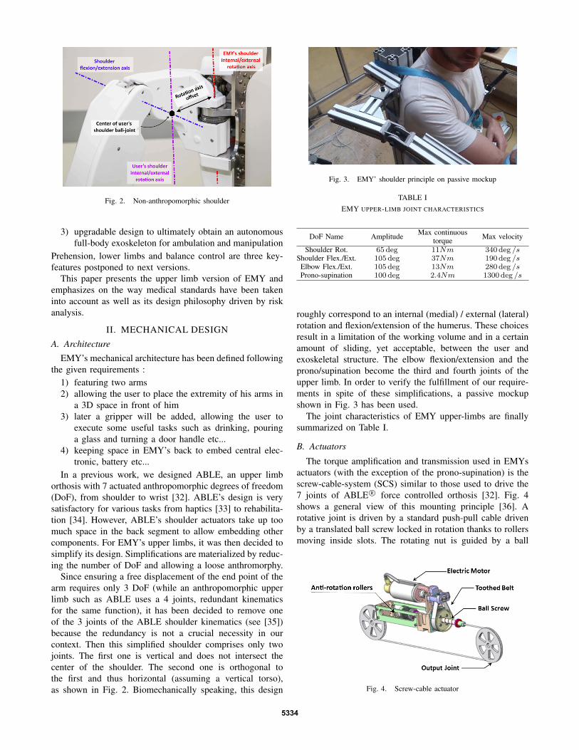
Fig. 2. Non-anthropomorphic shoulder
3) upgradable design to ultimately obtain an autonomousfull-body exoskeleton for ambulation and manipulation
Prehension, lower limbs and balance control are three key-features postponed to next versions.
This paper presents the upper limb version of EMY andemphasizes on the way medical standards have been takeninto account as well as its design philosophy driven by riskanalysis.
II. MECHANICAL DESIGN
A. Architecture
EMY’s mechanical architecture has been defined followingthe given requirements :
1) featuring two arms2) allowing the user to place the extremity of his arms in
a 3D space in front of him3) later a gripper will be added, allowing the user to
execute some useful tasks such as drinking, pouringa glass and turning a door handle etc...
4) keeping space in EMY’s back to embed central elec-tronic, battery etc...
In a previous work, we designed ABLE, an upper limborthosis with 7 actuated anthropomorphic degrees of freedom(DoF), from shoulder to wrist [32]. ABLE’s design is verysatisfactory for various tasks from haptics [33] to rehabilita-tion [34]. However, ABLE’s shoulder actuators take up toomuch space in the back segment to allow embedding othercomponents. For EMY’s upper limbs, it was then decided tosimplify its design. Simplifications are materialized by reduc-ing the number of DoF and allowing a loose anthromorphy.
Since ensuring a free displacement of the end point of thearm requires only 3 DoF (while an anthropomorphic upperlimb such as ABLE uses a 4 joints, redundant kinematicsfor the same function), it has been decided to remove oneof the 3 joints of the ABLE shoulder kinematics (see [35])because the redundancy is not a crucial necessity in ourcontext. Then this simplified shoulder comprises only twojoints. The first one is vertical and does not intersect thecenter of the shoulder. The second one is orthogonal tothe first and thus horizontal (assuming a vertical torso),as shown in Fig. 2. Biomechanically speaking, this design
Fig. 3. EMY’ shoulder principle on passive mockup
TABLE IEMY UPPER-LIMB JOINT CHARACTERISTICS
DoF Name Amplitude Max continuous Max velocitytorqueShoulder Rot. 65 deg 11Nm 340 deg /s
Shoulder Flex./Ext. 105 deg 37Nm 190 deg /sElbow Flex./Ext. 105 deg 13Nm 280 deg /sProno-supination 100 deg 2.4Nm 1300 deg /s
roughly correspond to an internal (medial) / external (lateral)rotation and flexion/extension of the humerus. These choicesresult in a limitation of the working volume and in a certainamount of sliding, yet acceptable, between the user andexoskeletal structure. The elbow flexion/extension and theprono/supination become the third and fourth joints of theupper limb. In order to verify the fulfillment of our require-ments in spite of these simplifications, a passive mockupshown in Fig. 3 has been used.
The joint characteristics of EMY upper-limbs are finallysummarized on Table I.
B. Actuators
The torque amplification and transmission used in EMYsactuators (with the exception of the prono-supination) is thescrew-cable-system (SCS) similar to those used to drive the7 joints of ABLE R© force controlled orthosis [32]. Fig. 4shows a general view of this mounting principle [36]. Arotative joint is driven by a standard push-pull cable drivenby a translated ball screw locked in rotation thanks to rollersmoving inside slots. The rotating nut is guided by a ball
Fig. 4. Screw-cable actuator
5334

Fig. 5. EMY forearm pronosupination
bearing and driven by the motor thanks to a timing belt. Thisdesign avoids the conventional linear guide for the screw andworks in synergy with the cable [37] by isolating the screwfrom perturbating bending moment which in turns guaranteesa regular and minimum friction along its full travel - i.e. alinear torque transfer and consequently a high efficiency.
Even if the stiffness is limited by the presence of the cableas compared with a gear, this property is rather an advantagethan drawback in this context because it brings some usefulcompliance then a higher safety. Further important advan-tages of the SCS for a wearable robotic device are its abilityto integrate the electrical motor alongside the limbs and itsparticularly silent operation.
The forearm prono-supination is achieved as shown inFig. 5 via a patented parallel structure [38] made of 3 rodsarticulated on ball-joints. These rods connect a rotating archto a fixed arch. An additional fixed cantilever mast ensuresthe circular trajectory of the mobile arch thanks to 3 rollersguided in a dedicated slot. In terms of mechanical structure,the system balances the shear force and the bending momentby two distinct devices, each being optimized for its function.This leads to a particularly lightweight, low inertia and lowfriction guiding mechanism even under load. The motor usedis an ironless brushed DC motors as on every joints ofEMY. It drives a shaft equipped with a double U-joint whichtransmits the torque to a pinion driving a gear sector.
III. ELECTRONIC DESIGN
A. Divide et impera
Because the safety assessment of a monolithic controller isa rather tedious task, a divide et impera principle has beenapplied in order to split EMY control system into severalsubsystems with independent hardware and software. Thispermits reducing the safety class inheritance for medicaldevice software described in ISO 62304 4.3.d [30] as soonas hazard is likely to occur in a subsystem only. Furthermorethis decentralized architecture eases the wiring integration byavoiding the use of a central node for all wired signals.
As depicted in Fig. 6, EMY architecture is composed of 4Motor Control Subsystems (MCS) embedded along EMY’slimb and some central components located in EMY’s back.Each MCS is able to drive two DoF.
Fig. 6. System layout and components
A wiring harness embedded into each limbs is gatheringthree electrical buses in order to interconnect subsystems.The first one is a power bus supplying energy to thesubsystems. The second one is a CAN fieldbus for datacommunication between MCS and central controller. Thelast one is a life bus dedicated to safety. This bus features aring topology and acts as a watchdog searching for defectivecomponents.
B. Motor Control Subsystem
Most industrial servo controllers available on the market,like the EPOS2 from Maxon Motor, have shapes that makethem difficult to embed along an exoskeleton limb and theydo not offer enough versatility to drive our screw-cableactuators with a suitable current/torque control loop [39].For these reasons, a custom motor control electronics hasbeen developed for EMY purposes. Each Motor ControlSubsystem (MCS) is able to control up to two 200W DCmotors and embeds :• a F28335 Texas instruments microcontroller (MCU)• two optical coder interfaces• four 12-bits analog/digital converters (ADC). Two of
them acquire joint absolute positions via potentiometerswhile the two others acquire the electrical current foreach motor
• two H-Bridge that modulate motor voltages accordingto PWM signals
• an hardware watchdog that inhibits H-bridges in caseof any problem
• a CAN bus to communicate with other subsystems
C. Central components
EMY’s central segment located in EMY’s back and shownin Fig. 7 is used to support mechanical attachment to limbsand to embed various equipments:• Two mini-ITX Intel i7-3770 computers. The first one is
used for overall robot control while the second one isdedicated to BMI signal processing.
• A WiFi interface and its antennae• Some mechanical buttons for hardware HMI• A 1500W AC/DC converter, replaceable by a 500Wh
Lithium Battery• A safety grade Programmable Logic Controller (PLC)
5335

Fig. 7. EMY’s central segment
• A power board manageable with the PLC to supplyvarious voltage to the overall system
IV. CONTROL SOFTWARE
A. Joint controllers
Joint controllers are implemented in the firmware of eachMCS. These key components in EMY architecture act aslifeguards for any higher level software. The main role ofjoint controllers is to safely drive EMY motors to followjoint references coming from central controller. As safety isthe key feature of joint controllers, a strong attention hasbeen paid to implement MCS firmware.
First of all, a Model Based Design coupled to a CodeGeneration solution has been employed to ease safety as-sessment and verification at every possible level from spec-ification phase to final implementation while preservingflexibility. Mathworks Simulink R©, Embedded Coder R© andReport Generator R© have been intensively used to generate C-code and maintain test cases, test reports and documentationduring all steps of development following ISO 62304 [30].
Torque control is a vital necessity in our applicationwhere user and robot are linked together. Our implementationof this control is based on the basic principle of relyingexclusively upon the open loop torque transfer using a me-chanically linear torque amplification and the current of themotor as torque signal. This principle has been extensivelydeveloped in servomanipulators in the nuclear industry, onthe WAM BarrettTM[40] and in most desktop haptic masterarms.
In order to maximize performances without compromisingsafety margins, performance and safety requirements aretranslated to H∞ and pole placement specifications. The con-troller parameters are tuned according to these specificationsusing non smooth optimization [41].
B. Central controller
The main role of the central controller is to convert inten-tions of movement coming from BMI into joint referencesfor each joint controllers.
Since EMY’s architecture is not strictly anthropomorphic,a virtual human coupled to a virtual EMY is internally used
to mask robot architecture to BMI. Intentions of movementcaptured from the BMI are then referenced on this humanmodel instead of a robot model: they are used to movethe limbs of the virtual human. Since the virtual human iscoupled to the virtual exoskeleton, the virtual exoskeleton ismoving to follow the virtual human motion as far as it ismechanically possible.
A current joint state of virtual EMY is then used as areference for the joint controllers.
In order to be used by various BMI, three control modeshave been implemented in central controller. The first one isstraightforward and corresponds to position and/or velocityin user’s joint space. The second mode is a Cartesian controlin position and/or velocity of each arm’s extremity. In thiscase, prono-supination is locked to a neutral position. Thelast one is an enhancement of the second mode with a controlof each prono-supination via articular references.
V. RISK MANAGEMENT
A. Approach
Risk management is a central concept in medical standardsand ISO 14971 [28] specifically defines application of riskmanagement to medical devices. The concept of risk isdefined as a combination of a probability of occurrence ofharm and of its severity.
Risk analysis is the indicated process to reference allpossible hazards (defined as a potential source of harm)and estimate their probability and their severity. For EMY,risk identification (ISO 14971 4.3) was based on knownand foreseeable hazards established in table E.1 of ISO14971 while a semi-quantitative risk analysis (ISO 14971D.3.4.2) was conducted in order to evaluate the acceptabilityof each referenced risk. The evaluation matrix shown in TableII has finally been employed to evaluate necessity of riskreductions.
B. Main hazards
The risk management process has been performed forEMY upper limb exoskeleton following ISO 14971 [28].As EMY risk analysis takes into account 80 hazards, onlya few of them are described in this subsection. Followingrisks have been selected regarding the large impact of theircorresponding control measures on EMY design.
1) Joint dislocation: Excess angle beyond the user’s me-chanical tolerable limit has been identified as a serious harmwhose the severity and the probability of occurrence areMAJOR and PROBABLE. Evaluation matrix shown in TableII indicates that it should be considered as an Undesirableand unacceptable risk.
Hard joint limits have then been implemented whoseamplitudes are reported in Table I, decreasing the probabilityto this risk to IMPROBABLE and resulting in a Negligiblerisk.
2) Unsuitable joint torques or velocities: Excess torqueor velocity even in hard joint limits have been considered asa possible harm due to the potential auto-collisions between
5336

TABLE IISEMI-QUANTITATIVE 5X5 RISK EVALUATION MATRIX USED FOR EMY
ProbabilityFREQ PROB OCCA REMO IMPR
Seve
rity
CATA Into Into Into UndR UndTCRIT Into Into UndR UndT NeglMAJ Into UndR UndT UndT NeglMIN UndR UndT UndT Negl Negl
NEGL UndT Negl Negl Negl Negl
Probability of harm is defined as :FREQ Can happen at every usePROB Could happen once in device life with normal usage conditionsOCCA Could happen once in device life with particular usage conditionsREMOCould technically happen but no history on similar devicesIMPR Can not happen regarding to current knowledge
Severity of harm is defined as :CATA Results in patient deathCRIT Results in permanent impairment of life-threatening injuryMAJ Results in injury or impairment requiring professional medical
interventionMIN Results in temporary injury or impairment not requiring profes-
sional medical interventionNEG Inconvenience or temporary discomfort
Acceptability of risk is defined as :
Into Intolerable risk: need inherent safety measure(s)
UndR Undesirable and unacceptable risk: need inherent safety mea-sure(s) or a protective measure(s)
UndT Undesirable but tolerable risk if no measure can be implemented:require at least safety information
Negl Insignificant risk: can result in safety information
limbs and collisions against environment. Severity and prob-ability have been evaluted to MINOR and PROBABLE, givingan Undesirable but tolerable risk.
In order to decrease the probability of such an hazard,software saturations on joint velocities and torques have beenimplemented in joint controllers. Consequently, each MCSfirmware becomes a class B software regarding to ISO 62304[30] since it prevents the user from an injury. Class B impliesa strong effort in validation and documentation (cf TableA.1 in ISO 62304). Mathworks tools help us to fulfill theserequirements in MCS firmware.
3) Electrical hazards: ISO 60601-1 [29] carefully takesinto account electrical hazards due to the fact that patientsmay not have the same vulnerability and reflexes than healthypeople. For illustration, ISO 60204-1 [42] relative to safety ofnon-medical electrical machines requires that earth leakagecurrents are less than 10mA in normal condition while ISO60601-1 requires that earth leakage currents are less than10mA in single fault condition and that patient leakagecurrents are less than 10µA in normal condition and lessthan 50µA in single fault condition.
Before any specific consideration in EMY’s design, sever-ity and probability of occurrence of electrical hazard has beenevaluated to CATASTROPHIC and OCCASIONAL, resultingin an Intolerable risk.
Regarding electrical safety, the power supply is a deter-mining component. AC/DC converter embedded in EMYhas a medical grade and includes two Means of PatientProtection (MOPP). All external parts have been considered
as B applied part (cf ISO 60601-1) and all metal parts arelinked to share same electrical potential.
Expertise of an external test laboratory has finally beenemployed to validate the conformity of EMY to requirementsof ISO 60601-1 in terms of electrical safety.
4) Joint desynchronization: Due to the topology of EMYelectronic architecture, partial failure of the system has beenconsidered as an harm since it can potentially result injoint desynchronization. The severity and the probability ofoccurrence of this harm has been evaluated to MINOR andPROBABLE, giving the resulting acceptability as Undesir-able but tolerable risk.
The corresponding protective measure is the usage of thePLC to inspect the system via the life bus for detecting poten-tial defective components and to command power extinctionin case of any problem.
C. Residual hazards
After achieving the implementation of safety and protec-tive measures induced by each of the 80 risks identifiedduring risk management process, only one Undesirable Riskhas been remaining. It corresponds to crushing hazard (ISO60601-1 Table 19 [29]) nearby EMY’s joints. This harmconcerns directly an additional person rather than the patienthimself whose hands are at the extremity of EMY’s arm.As joint movements remain within this additional person’sfield of view (ISO 60601-1 9.2.2.5.a), the severity and theprobability of occurrence of this harm has been evaluated toMAJOR and OCCASIONAL, resulting in an Undesirable buttolerable risk.
As risk control measures, two remote emergency stop but-tons have been implemented while the user manual explicitlywarns the operators to this residual risk of crushing.
VI. CONCLUSIONS & FUTURE WORKS
EMY is an exoskeleton dedicated to the evaluation of aBMI in clinical trials whose first version is restricted to upperlimbs. This paper described a stage in the development ofEMY, particularly the description of the design and how thedesign eliminates possible risks, in line with the requirementsfor a clinical trial.
The next step will consist in the evaluation and usage ofEMY during clinical trials with disabled subjects.
As this first version of EMY can be alternatively poweredby an embedded Lithium battery, it can already be mountedon a wheelchair. However, future upgrades of EMY willconcern the addition of lower limbs to obtain a full-bodyexoskeleton suitable for testing brain controlled locomotiontasks. Balance and fall prevention will then become chal-lenging features to consider with strong attention.
Furthermore, complementing EMY with the prehensioncapability using either simple gripper or a more sophisticatedactuated glove will also be considered as a future upgradebecause it corresponds to a vivid need for quadriplegicpersons.
5337

ACKNOWLEDGMENT
We gratefully acknowledge the help of Romain Fischesser,Pascal Chambaud and Philippe Pottier, who were deeplyinvolved in technical development of EMYs components.
REFERENCES
[1] T. Bradberry, R. Gentili, and J. Contreras-Vidal, Reconstructingthreedimensional hand movements from noninvasive electroencephalo-graphic signals, in The Journal of Neuroscience, Volume: 30, Issue:9, 2010, pp. 34323437
[2] J.R. Wolpaw, D.J. McFarland, G.W. Neat, C.A. Forneris, An EEG-based brain-computer interface for cursor control, in Electroen-cephalography and chinical Neurophysiology, Volume: 78, Issue: 3,1991, pp. 252-260
[3] G. Schalk, K.J. Miller, N.R. Anderson, et al, Two-dimensional move-ment control using electrocorticographic signals in humans, in Journalof Neural Engineering, Volume: 5, Issue: 1, 2008, pp. 75-84
[4] C. Mestais, G. Charvet, F. Sauter-Starace, M. Foerster, D. Ratel,A.L. Benabid, WIMAGINE: Wireless 64-Channel ECoG RecordingImplant for Long Term Clinical Applications, in IEEE Transactions onNeural Systems and Rehabilitation Engineering Conference on NeuralEngineering, Volume 23, 2015, pp. 10-21
[5] J.D. Simeral, S.P. Kim, M.J. Black, J.P. Donoghue, L.R. Hochberg,Neural control of cursor trajectory and click by a human withtetraplegia 1000 days after implant of an intracortical microelectrodearray, in Journal of Neural Engineering, Volume: 8, Issue: 2, 2011, p.025027
[6] J.P. Donoghue, Bridging the Brain to the World: A Perspective onNeural Interface Systems, in Neuron, Volume: 60, Issue 3, November2008, pp. 511-521
[7] A.B. Schwartz, X.T. Cui, D.J. Weber, D.W. Moran, Brain-controlledinterfaces: movement restoration with neural prosthetics, in Neuron,Volume: 52, Issue 1, October 2006, pp. 205-224
[8] B. Rebsamen, E. Burdet, et al, Controlling a wheelchair indoors usingthought, in IEEE Intelligent Systems, pp. 1824, Mar./Apr. 2007.
[9] T. Carlson, J. del R Millan, BrainControlled Wheelchairs: A RoboticArchitecture, in IEEE Robotics and Automation Magazine, Volume:20, Issue: 1, March 2013, pp. 65-73
[10] C. Escolano, A.R. Murguialday, T. Matuz, N. Birbaumer, J. Minguez,A telepresence robotic system operated with a P300-based brain-computer interface: Initial tests with ALS patients, in Engineeringin Medicine and Biology Society (EMBC), 32th Annual InternationalConference of the IEEE, 2010, pp. 4476-4480
[11] C. Escolano, J.M. Antelis, J. Minguez, A Telepresence Mobile RobotControlled With a Noninvasive BrainComputer Interface, in IEEETransactions on Systems, Man and Cybernetics, Part B: Cybernetics,Volume: 42, Issue: 3, 2012, pp. 793-804
[12] C.E. King, P.T. Wang, M. Mizuta, D.J. Reinkensmeyer, A.H. Do, S.Moromugi, Z. Nenadic, Noninvasive brain-computer interface drivenhand orthosis, in Engineering in Medicine and Biology Society(EMBC), 33th Annual International Conference of the IEEE, 2011,pp. 4476-4480
[13] L. R. Hochberg, D. Bacher, B. Jarosiewicz, N. Y. Masse, et al., Reachand grasp by people with tetraplegia using a neurally controlled roboticarm, in Nature, vol. 485, May 17 2012, pp. 372-5.
[14] P. Maciejasz, J. Eschweiler, K. Gerlach-Hahn, A. Jansen-Toy, S.Leonhardt, A survey on robotic devices for upper limb rehabilitation,in Journal of NeuroEngineering and Rehabilitation, Volume 11, 2014,pp. 3-31
[15] S. Ho Shing, X. Sheng Quan, Exoskeleton robots for upper-limb reha-bilitation: State of the art and future prospects, in Medical Engineering& Physics, Volume: 34, Issue: 3, April 2012, pp. 261-268
[16] Bionics Research Inc., ReWalk, http://www.rewalk.com/[17] REX Bionics Ltd., REX, http://www.rexbionics.com/[18] RB3D S.A., HERCULE V3, http://www.rb3d.com/en/exoskeletons/[19] Cyberdyne Inc., HAL, http://www.cyberdyne.jp/english/[20] Ekso Bionics, Ekso, http://intl.eksobionics.com/
[21] E. Guizzo, H. Goldstein, The rise of the body bots [robotic exoskele-tons], in IEEE Spectrum, Volume: 42, Issue: 10, pp. 50-56.
[22] T. Yoshimitsu, K. Yamamoto, Development of a power assist suit fornursing work, in SICE 2004 Annual Conference, 2004, pp. 577-580
[23] M. Fontana, R. Vertechy, S. Marcheschi, F. Salsedo, M. Bergamasco,The Body Extender: A Full-Body Exoskeleton for the Transport andHandling of Heavy Loads, in IEEE Robotics & Automation Magazine,Volume: 21, Issue: 4, 2012, pp. 34-44
[24] A. Kilicarslan, S. Prasad, R. G. Grossman, J. L. Contreras-Vidal, HighAccuracy Decoding of User Intentions Using EEG to Control a Lower-Body Exoskeleton, in Engineering in Medicine and Biology Society(EMBC), 35th Annual International Conference of the IEEE, 2013, p.5606-5609.
[25] Council Directive 93/42/EEC of 14 June 1993 concerning MedicalDevices, in Official Journal L 169
[26] ISO, ISO 14155, Clinical investigation of medical devices for humansubjects - Good clinical practice, Geneva, Switzerland: InternationalOrganization for Standardization, 2012
[27] ISO, ISO 13482, Robots and robotic devices Safety requirements forpersonal care robots, Geneva, Switzerland: International Organizationfor Standardization, 2014
[28] ISO, ISO 14971, Medical devices - Application of risk management tomedical devices, Geneva, Switzerland: International Organization forStandardization, 2012
[29] ISO, ISO 60601-1, Medical electrical equipment - Part 1: Generalrequirements of basic safety and essential performance, Geneva,Switzerland: International Organization for Standardization, 2007
[30] ISO, ISO 62304, Medical device software - Software life cycle pro-cesses, Geneva, Switzerland: International Organization for Standard-ization, 2006
[31] A. Eliseyev, CLINATEC BCI platform based on the ECoG-recordingimplant WIMAGINE and the innovative signal-processing: preclinicalresults, in Engineering in Medicine and Biology Society (EMBC), 36thAnnual International Conference of the IEEE, 2014, p. 1222-1225.
[32] P. Garrec, J. Friconneau, Y. Measson, and Y. Perrot, ABLE, aninnovative transparent exoskeleton for the upper-limb, in IEEE/RSJInternational Conference on Intelligent Robots and Systems, 2008, pp.1483-1488
[33] Haption, ABLE, http://www.haption.com/site/index.php/en/products-menu-en/hardware-menu-en/37-able-content-en
[34] N. Jarrasse, J. Robertson, P. Garrec, J. Paik, V. Pasqui, Y. Perrot,A. Roby Brami, D. Wang, G. Morel, Design and AcceptabilityAssessment of a New Reversible Orthosis, in IEEE/RSJ InternationalConference on Intelligent Robots and Systems, 2008, pp. 1933-1939
[35] P. Garrec, Shoulder mechanism for orthosis, US Patent N20120172769, WO Patent N 2011029564 A3, September 2009 (prior-ity)
[36] P. Garrec, Screw and nut transmission and cable attached to the screw,U.S. Patent No. 7073406, WO Patent No. 2001092761, May 2000(priority)
[37] P. Garrec, Screw and cable actuators (scs) and their applicationsto force feedback teleoperation, exoskeleton and anthropomorphicrobotics, in Robotics 2010 Current and Future Challenges, 2010
[38] P. Garrec, Forearm rotation mechanism and orthosis including suchmechanism, U.S. Patent No. 8460222, WO Patent No. 2008155286A1, June 2007 (priority)
[39] N. Abroug, B. Moriniere, Enhancing Motor Torque Control by imple-menting H-infinity Controller and compensating Electronics Nonlin-earities, in IEEE International Symposium on Industrial Electronics,2014
[40] Barrett Technology Inc., WAM Arm,http://www.barrett.com/robot/products-arm.htm
[41] N. Abroug, E. Laroche, Structured H∞ framework for impedanceminimization on robot arm with compliant actuation, in Multi Confer-ence on Systems and Control, 2014
[42] ISO, ISO 60204-1, Safety of machinery - Electrical equipementof machines - Part 1: General requirements, Geneva, Switzerland:International Organization for Standardization, 2006
[43] http://www.instituts-carnot.eu
5338