en 001 use sv-15 r4 - roland care service &...
TRANSCRIPT

USER'S MANUAL
Thank you very much for purchasing this product.
➢ To ensure correct and safe usage with a full understanding of this product's performance, please besure to read through this manual completely and store it in a safe location.
➢ Unauthorized copying or transferral, in whole or in part, of this manual is prohibited.➢ The contents of this operation manual and the specifications of this product are subject to change
without notice.➢ The operation manual and the product have been prepared and tested as much as possible. If you
find any misprint or error, please inform us.➢ Roland DG Corp. assumes no responsibility for any direct or indirect loss or damage which may
occur through use of this product, regardless of any failure to perform on the part of this product.➢ Roland DG Corp. assumes no responsibility for any direct or indirect loss or damage which may
occur with respect to any article made using this product.

For the USA
FEDERAL COMMUNICATIONS COMMISSIONRADIO FREQUENCY INTERFERENCE
STATEMENT
This equipment has been tested and found to comply with thelimits for a Class A digital device, pursuant to Part 15 of the FCCRules.These limits are designed to provide reasonable protectionagainst harmful interference when the equipment is operated ina commercial environment.This equipment generates, uses, and can radiate radio frequencyenergy and, if not installed and used in accordance with theinstruction manual, may cause harmful interference to radiocommunications.Operation of this equipment in a residential area is likely tocause harmful interference in which case the user will berequired to correct the interference at his own expense.
Unauthorized changes or modification to this system can voidthe users authority to operate this equipment.
The I/O cables between this equipment and the computingdevice must be shielded.
For Canada
CLASS A NOTICE
This Class A digital apparatus meets all requirements of theCanadian Interference-Causing Equipment Regulations.
CLASSE A AVIS
Cet appareil numérique de la classe A respecte toutes lesexigences du Règlement sur le matériel brouilleur duCanada.
WARNINGThis is a Class A product. In a domestic environment this product may cause radio interference in which case the usermay be required to take adequate measures.
Manufacturer:ROLAND DG CORPORATION1-6-4 Shinmiyakoda, Kita-ku, Hamamatsu-shi, Shizuoka-ken, 431-2103 JAPAN
The authorized representative in the EU:Roland DG Corporation, German Office Halskestr.7 47877 Willich,Germany
For EU Countries
For EU Countries
WARNINGThis product contains chemicals known to cause cancer,birth defects and other reproductive harm, includinglead.
For California
Roland DG Corp. has licensed the MMP technology from the TPL Group.

1
Contents
Read This First ....................................................................................................................................... 3
Machine Functions ........................................................................................................................................................ 3
To Ensure Safe Use ....................................................................................................................... 6
Important Notes on Handling and Use ........................................................................................... 10
Chapter 1: Setup Preparation ........................................................................................................... 11
1-1 Included Items ...................................................................................................................................................... 121-2 Part Names ............................................................................................................................................................ 13
Main Unit ...................................................................................................................................... 131-3 Installing .................................................................................................................................................................. 14
Deciding On an Installation Site ................................................................................................... 14Installation Space .......................................................................................................................... 14Removing the Packing Materials .................................................................................................... 15Connecting the Cables .................................................................................................................. 16
Chapter 2: Installing Software ........................................................................................................... 17
2-1 About the Included Software ............................................................................................................................ 182-2 If You're Using a Windows ................................................................................................................................. 19
System Requirements .................................................................................................................... 19Installing the Software ................................................................................................................... 20
2-3 If You're Using a Macintosh ................................................................................................................................ 23System Requirements .................................................................................................................... 23Installing the Software ................................................................................................................... 23
Chapter 3: Performing Cutting ......................................................................................................... 25
3-1 What to Know Before Cutting ......................................................................................................................... 26Useable Material Types ................................................................................................................. 26
3-2 Cutting .................................................................................................................................................................... 28Step 1: Load Material .................................................................................................................... 28Step 2: Create Cutting Data ........................................................................................................... 30Step 3: Perform Cutting ................................................................................................................. 34Step 4: Apply the Cut Material ...................................................................................................... 36
Chapter 4: Mastering the STIKA ...................................................................................................... 37
4-1 Optimizing the Cutting Quality for the Material ......................................................................................... 38Check the Cutting Quality for the Material .................................................................................... 38Adjusting the Blade Extension Amount .......................................................................................... 39
4-2 Correcting the Angle of the Loaded Material ............................................................................................... 404-3 About Creating Cutting Data ............................................................................................................................ 41
Creating Various Text Data ............................................................................................................. 41Creating Contour Data by Reading a BMP/JPG Format File ........................................................... 43Deleting Undesired Cutting Lines .................................................................................................. 45
4-4 Applying Large Materials .................................................................................................................................... 46

Contents
2
Copyright© 2005-2008 Roland DG Corporation
CutStudio is a trademark of Roland DG Corp.
Windows® is either a registered trademark or trademark of Microsoft® Corporation in the United States and/or other countries.Macintosh and Mac OS are registered trademarks or trademarks of Apple Computer, Inc. in the USA and other countries.Adobe and Adobe Illustrator are either registered trademarks or trademarks of Adobe Systems Incorporated in the United States and/or other coun-tries.Corel and CorelDRAW are registered trademarks or trademarks of Corel Corporation or Corel Corporation Limited.
Other company names and product names are trademarks or registered trademarks of their respective holders.
http://www.rolanddg.com/
Chapter 5: Maintenance ..................................................................................................................... 47
5-1 Maintenance .......................................................................................................................................................... 48Cleaning the Blade Tip .................................................................................................................. 48Cleaning the Blade Holder ............................................................................................................ 48Cleaning the Main Unit ................................................................................................................. 48
5-2 Replacing Consumables ...................................................................................................................................... 49Replacing the Blade ...................................................................................................................... 49Replacing the Blade Protector ....................................................................................................... 50
Chapter 6: Appendix ........................................................................................................................... 53
6-1 What to Do If ....................................................................................................................................................... 54The machine does not run properly ............................................................................................... 54The cut incisions are not clean ...................................................................................................... 54Parts of the material are not continuously cut ................................................................................ 54The cut location is shifted forward/back ........................................................................................ 54The cut location is shifted left/right ............................................................................................... 54The material shifts during cutting .................................................................................................. 55If the driver cannot be installed ..................................................................................................... 55Uninstalling the driver ................................................................................................................... 56
6-2 Shaft Lubrication .................................................................................................................................................. 576-3 Cutting Range ....................................................................................................................................................... 586-4 Locations of the Power Rating and Serial Number Labels ........................................................................ 596-5 Specifications ......................................................................................................................................................... 60

3
Read This First
Machine Functions
For Windows
➢You can use the included cutting software "Roland CutStudio" to create stickers and stickers with images.• CutStudio Overview, Installation Method ☞ User's Manual (this document) p 18
CutStudio
You can use your own designs to create original stickers.
☞ User’s Manual (this document) p 28
You can use STIKA in combination with a printer to create stickers with images.
☞ Windows Advanced Guide (electronic format)
CutStudio
STIKA Sticker
STIKA Sticker with imagePrinter
Illustrator+
CutStudio
You can make stickers with data created in Illustrator.
☞ Windows Advanced Guide (electronic format)
Illustrator+
CutStudio
You can use STIKA in combination with a printer to create stickers with images.
☞ Windows Advanced Guide (electronic format)
STIKA Sticker
STIKA Sticker with imagePrinter
➢You can use the included Adobe Illustrator software plug-in "CutStudio Plug-in for Adobe Illustrator" to sendcutting data created in Illustrator to CutStudio and create stickers and stickers with images.• Software plug-in overview, installation method ☞ Windows Advanced Guide (electronic format)

Read This First
4
You can create stickers with data created in CorelDRAW.
☞ Windows Advanced Guide (electronic format)
➢You can use the included software "STIKA Navi" to operate STIKA from your computer. Operation is simple;just follow the instructions displayed on your computer screen.• STIKA Navi Overview ☞ Windows Advanced Guide (electronic format)
CorelDRAW+
CutStudio
You can run a material jam test.
☞ Windows Advanced Guide (electronic format)
You can cut in areas of the material that have not yet been cut.
☞ Windows Advanced Guide (electronic format)
STIKA Sticker
STIKA Navi Operation ScreenSTIKAClick
STIKAClick
STIKA Navi Operation Screen
Unused part
➢You can use the included CorelDRAW software plug-in "CutStudio Plug-in for CorelDRAW" to send datacreated in CorelDRAW to CutStudio and create stickers.• Software plug-in overview, installation method ☞ Windows Advanced Guide (electronic format)

Read This First
5
You can create stickers with data created in Illustrator.
☞ Macintosh Cutting Guide (electronic format)
Illustrator+
CutStudio STIKA Sticker
For Macintosh
➢You can use the included software plug-in "CutStudio Plug-in for Adobe Illustrator" to make stickers with datacreated in Illustrator.• Software plug-in overview, installation method ☞ User's Manual (this document) p 23

6
Used for instructions intended to alert the user to the risk of death or severeinjury should the unit be used improperly.
About WARNING and CAUTION Notices
Used for instructions intended to alert the user to the risk of injury or materialdamage should the unit be used improperly.
* Material damage refers to damage or other adverse effects caused with re-spect to the home and all its furnishings, as well to domestic animals or pets.
WARNING
CAUTION
About the Symbols
The symbol alerts the user to important instructions or warnings. The specific meaning ofthe symbol is determined by the design contained within the triangle. The symbol at left means"danger of electrocution."
The symbol alerts the user to items that must never be carried out (are forbidden). Thespecific thing that must not be done is indicated by the design contained within the circle. Thesymbol at left means the unit must never be disassembled.
The symbol alerts the user to things that must be carried out. The specific thing that must bedone is indicated by the design contained within the circle. The symbol at left means the power-cord plug must be unplugged from the outlet.
To Ensure Safe Use
Improper handling or operation of this machine may result in injury or damage to property.Points which must be observed to prevent such injury or damage are described as follows.

To Ensure Safe Use
7
WARNING
Keep children away from the machine.The machine includes areas and componentsthat pose a hazard to children and may result ininjury, blindness, choking, or other serious acci-dent.
Never attempt to disassemble, repair, ormodify the machine.Doing so may result in fire, electrical shock, orinjury. Entrust repairs to a trained service tech-nician.
For accessories (optional and consumableitems, AC adapter, power cord, and thelike), use only genuine articles compatiblewith this machine.Incompatible items may lead to an accident.
Incorrect operation may cause injury
CAUTION
Caution: cutting tool.This machine has an internal tool. To avoid in-jury, handle the tool with care.
Before attempting cleaning, maintenance,or attachment or detachment of optionalitems, disconnect the power cord.Attempting such operations while the machineis connected to a power source may result ininjury or electrical shock.
Never use the machine for any purposefor which it is not intended, or use themachine in an undue manner that exceedsits capacity.Doing so may result in injury or fire.
Install in a location that is level and stable.Installation in an unsuitable location may causean accident, including a fall or tipover.

To Ensure Safe Use
8
WARNING
Connect to an electrical outlet that com-plies with this machine's ratings (for volt-age, frequency, and current).Incorrect voltage or insufficient current maycause fire or electrical shock.
Never use out of doors or in any locationwhere exposure to water or high humid-ity may occur. Never touch with wet hands.Doing so may result in fire or electrical shock.
Never allow any foreign object to get in-side. Never expose to liquid spills.Inserting objects such as coins or matches orallowing beverages to be spilled into the venti-lation ports may result in fire or electrical shock.If anything gets inside, immediately disconnectthe power cord and contact your authorizedRoland DG Corp. dealer.
Never place any flammable object nearby.Never use a combustible aerosol spraynearby. Never use in any location wheregases can accumulate.Combustion or explosion may be a danger.
WARNING
Handle the power cord, plug, and electri-cal outlet correctly and with care. Neveruse any article that is damaged.Using a damaged article may result in fire orelectrical shock.
When using an extension cord or powerstrip, use one that adequately satisfies themachine's ratings (for voltage, frequency,and current).Use of multiple electrical loads on a single elec-trical outlet or of a lengthy extension cord maycause fire.
When the machine will be out of use for aprolonged period, disconnect the powercord.This can prevent accidents in the event of cur-rent leakage or unintended startup.
Position so that the power plug is withinimmediate reach at all times.This is to enable quick disconnection of thepower plug in the event of an emergency. Installthe machine next to an electrical outlet. Also,provide enough empty space to allow immedi-ate access to the electrical outlet.
If sparking, smoke, burning odor, unusualsound, or abnormal operation occurs, im-mediately unplug the power cord. Neveruse if any component is damaged.Continuing to use the machine may result in fire,electrical shock, or injury. Contact your autho-rized Roland DG Corp. dealer.
Ratings
Danger of electrical short, shock, electrocution, or fire

To Ensure Safe Use
9
Important notes about the power cord, plug, and electrical outlet
Never place any object on top or subject todamage.
Never bend or twist with undue force.
Never pull with undue force.
Never bundle, bind, or roll up.
Never allow to get wet.
Never make hot.
Dust may cause fire.

10
Important Notes on Handling and Use
This machine is a precision device. To ensure the full performance of this machine, be sure to observe thefollowing important points. Failure to observe these may not only result in loss of performance, but may alsocause malfunction or breakdown.
Main Unit
This Machine Is a Precision Device
➢Handle carefully, and never subject the machine to impact or excessive force.
Install in a Suitable Location
➢ Install in a location having the specified temperature and relative humidity.➢ Install in a stable location offering good operating conditions.
Important Notes on Connecting the Cables
➢Connect the power cord and the computer's input and output cables securely.
When Moving the Machine
➢When moving the machine, be sure to support the machine at its bottom, using both hands. Attempting tomove the machine by holding it at a different location may damage the machine.

11
Chapter 1:Setup Preparation

Chapter 1: Setup Preparation12
1-1 Included Items
The following items are packed together with the unit. Make sure they are all present and accounted for.
* The blade, blade holder and pinare installed onto the machine.
Replaceable bladeprotector: 1
AC adapter: 1 Power cord: 1 USB cable: 1
Blade: 1 Blade holder: 1Pin: 1
Test-use material(Colored material): 1
Test-use application tape(Transparent tape): 1
CD-ROM: 1 User's Manual: 1
* The shape depends on the model.

Chapter 1: Setup Preparation 13
1-2 Part Names
Main Unit
Power button
USB connector
Sheet feed knob
Blade protector
Blade holder
Shaft cover
AC adapter jack
Power light
* Sheet adjustment lever
Pinch rollers
* The SV-15 has sheet adjustment levers on the left and right. The SV-12/8 has a sheet adjustment lever only on theright.
Cutting carriage

Chapter 1: Setup Preparation14
1-3 Installing
Deciding On an Installation Site
Install in a stable location offering good operating conditions. An unsuitable location can cause accident, faultyoperation, or breakdown.
WARNING Never use out of doors or in any location where exposure to water or high humid-ity may occur. Never touch with wet hands.Doing so may result in fire or electrical shock.
WARNING Never place any flammable object nearby. Never use a combustible aerosol spraynearby. Never use in any location where gases can accumulate.Combustion or explosion may be a danger.
WARNING Position so that the power plug is within immediate reach at all times.This is to enable quick disconnection of the power plug in the event of an emergency.Install the machine next to an electrical outlet. Also, provide enough empty space toallow immediate access to the electrical outlet.
CAUTION Install in a location that is level and stable.Installation in an unsuitable location may cause an accident, including a fall or tipover.
Unsuitable Installation Sites
➢Locations subject to shaking or vibration➢Locations where the floor is tilted, not level, or unstable➢Dusty locations➢Locations exposed to considerable electrical or magnetic noise, or other forms of electromagnetic energy➢Locations with poor heat radiation
Installation SpaceThe material moves forward and backward duringcutting. Do not place any objects in front of orbehind the material. Make sure that there are noobstructions (such as a wall, etc.) behind themachine.
Leave enough space sothat the power cord canalways be reached.
Leave enough space sothat no objects touch thesheet feed knob.

1-3 Installing
Chapter 1: Setup Preparation 15
Removing the Packing Materials
Tape and packing materials are attached to the machine to protect it from shocks during transportation. When instal-lation is complete, remove these materials.
➢Remove all packing materials. Any that remain may cause faulty operation or breakdown when the power isswitched on.
Packing materials

1-3 Installing
Chapter 1: Setup Preparation16
Connecting the Cables
WARNING Connect to an electrical outlet that complies with this machine's ratings (for volt-age, frequency, and current).Incorrect voltage or insufficient current may cause fire or electrical shock.
WARNING Handle the power cord, plug, and electrical outlet correctly and with care. Neveruse any article that is damaged.Using a damaged article may result in fire or electrical shock.
WARNING When using an extension cord or power strip, use one that adequately satisfies themachine's ratings (for voltage, frequency, and current).Use of multiple electrical loads on a single electrical outlet or of a lengthy extension cordmay cause fire.
WARNING Use only brand-name AC adapters and power cords compatible with this machine.The use of an incompatible product could lead to an accident.
USB cable
AC adapter Jack
You make the connection to the computer using the included USB cable.Connect the USB cable at the time indicated in the driver installation procedures. Driver installation may fail andthe machine may become unusable if you connect a USB cable before starting installing the driver.
☞ p 20 "Installing the Driver"
Important Notes on USB Connection
➢Never use a USB hub or the like.
AC adapterPower cord
ElectricaloutletPower rating
DO NOT connecta USB cable atthis point.

17
Chapter 2:Installing Software
This section describes how to install the included software.

Chapter 2: Installing Software18
2-1 About the Included Software
The included CD-ROM contains the following software.
Software for Windows
■ STIKA Driver
This is a Windows-based driver required for sending data from a computer to the machine. Be sure to install it.
■ STIKA Navi
This is software that lets you operate the machine from Windows. It can be used to move the blade and test thematerial feed. It is automatically installed when the STIKA driver is installed.
■ Roland CutStudio
Roland CutStudio is software that allows you to create cutting data and easily perform cutting operations.
■ CutStudio Plug-in for Adobe Illustrator
This is an Illustrator software plug-in that lets you cut from data created in Adobe Illustrator.
■ CutStudio Plug-in for CorelDRAW
This is a CorelDRAW software plug-in that lets you cut from data created in CorelDRAW.
Software for Macintosh
■ CutStudio Plug-in for Adobe Illustrator
This is an Illustrator software plug-in that lets you cut from data created in Adobe Illustrator.

Chapter 2: Installing Software 19
2-2 If You're Using a Windows
System Requirements
System Requirements for USB Connection
Making a USB connection with Windows requires use of a computer that meets all of the following system require-ments. Please note that other configurations cannot be supported.
System Requirements for the Roland CutStudio
System Requirements for the STIKA Driver
Operating SystemsComputer
Windows 98 SE (Second Edition)/Me/2000/XP
1) Computers preinstalled with Windows 98 SE/Me/2000/XP at the time of purchase (This includes such computers later upgraded to Windows Me/2000/XP.)2) Computers on which USB operation is assured by the manufacturer of computers
Operating SystemsComputerDriveMonitor
Memory (RAM)Free hard-disk space required forinstallation
Windows 98 SE (Second Edition)/Me/2000/XP
Computer running Windows
CD-ROM drive
Windows-compatible monitor capable of displaying of 16 bit color (HighColor) or more
128 MB or more recommended
10 MB
Operating SystemsComputer
Windows 98 SE (Second Edition)/Me/2000/XP
1) Computers preinstalled with Windows 98 SE/Me/2000/XP at the time of purchase (This includes such computers later upgraded to Windows Me/2000/XP.)2) Computers on which USB operation is assured by the manufacturer of computers

2-2 If You're Using a Windows
20 Chapter 2: Installing Software
Installing the Software
Installing the Driver
STIKA Navi is installed along with the driver.
Do Not Connect to Computer Until Instructed
Do not connect the machine to the computer until instructed to do so. Failure to follow the correct procedure maymake installation impossible.
☞ p 54 "What to Do If"
Procedure
➊ Before you start installation and setup, make sure the USB cable is not connected.
➋ Log on to Windows. If you are installing under Windows 2000/XP, log on as "Administrators" right.
➌ Insert the included CD-ROM into the CD-ROMdrive.After a short wait, the setup menu shown at left ap-pears.
➍ Click [Install].The Installation and Setup Guide appears.If you're using Windows 98 SE, Windows Me, or Win-dows 2000, the Installation and Setup Guide and theSetup program appear.
➎ Follow the instructions in the Installation and Setup Guide to finish installing.
If the [Driver Setup] Window Doesn't Appear
If you're using Windows 98 SE, Windows Me, or Windows 2000 and the Setup program doesn't appear, firstcheck the taskbar at the bottom of the screen. If [Driver Setup] is displayed, the program is running. Go to thetaskbar and click [Driver Setup] to display the window for the Setup program.
Installation and Setup Guide
Setup program(Windows 98 SE/Me/2000)
Taskbar Click this.

2-2 If You're Using a Windows
Chapter 2: Installing Software 21
Installing CutStudio
Install the cutting software "CutStudio."
Procedure
➊ Display the setup menu of the Roland STIKA Soft-ware Package.
➋ Click [Install].The setup window appears.
➌ Thereafter, follow the instructions in the messages to complete installation and setup.
Next, you install the Windows Advanced Guide.
Viewing the Roland CutStudio Online Help
Click [Start], point to [All Programs] (or [Programs]), then point to [Roland CutStudio], point to [CutStudioHelp].
* You can also display the Online Help from the CutStudio menu.
2-2 If You're Using a Windows
22 Chapter 2: Installing Software
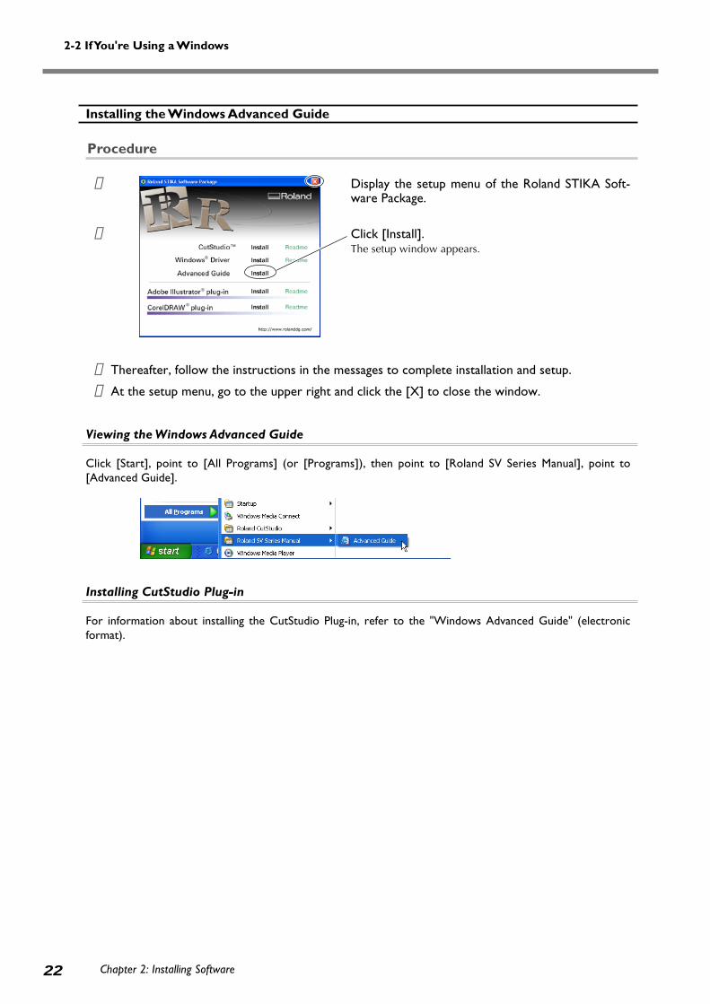
Installing the Windows Advanced Guide
Procedure
➊ Display the setup menu of the Roland STIKA Soft-ware Package.
➋ Click [Install].The setup window appears.
➌ Thereafter, follow the instructions in the messages to complete installation and setup.
➍ At the setup menu, go to the upper right and click the [X] to close the window.
Viewing the Windows Advanced Guide
Click [Start], point to [All Programs] (or [Programs]), then point to [Roland SV Series Manual], point to[Advanced Guide].
Installing CutStudio Plug-in
For information about installing the CutStudio Plug-in, refer to the "Windows Advanced Guide" (electronicformat).

Chapter 2: Installing Software 23
2-3 If You're Using a Macintosh
System Requirements
Your Macintosh must fulfill the following requirements in order to use STIKA for cutting operations.OS: Mac OS 9 or later (Adobe Illustrator 9/10/CS run without problem)
Installing the Software
The included CD-ROM contains the "Mac OS Installation and Setup Guide," which explains how to install and set upthe software and Macintosh Cutting Guide. If you’re using a Macintosh, follow the steps below to display the file, thenfollow the explanation to perform installation and setup.
Procedure
➊ Insert the included CD-ROM into the CD-ROM drive.
➋ Double-click the [Roland SV Series] icon that appears on the desktop.
➌ Double-click the "Install_e.html" icon.The [Mac OS Installation and Setup Guide] appears.
➍ Thereafter, follow the instructions in the [Mac OS Installation and Setup Guide] to install and setup the software and Macintosh Cutting Guide.

24

25
Chapter 3:Performing Cutting
This describes basic cutting operations under Windows. For other opera-
tions not covered in this chapter, refer to the "Windows Advanced Guide"
(electronic format).

26 Chapter 3: Performing Cutting
3-1 What to Know Before Cutting
Useable Material Types
The following materials can be used with this machine.
SV-15 SV-12 SV-8Width: 360 to 381 mm Width: 280 to 305 mm Width: 200 to 215 mm
(14-1/8 to 15 in.) (11 to 12 in.) (7-13/16 to 8-7/16 in.)280 to 305 mm (11 to 12 in.) (A3 length, A4 width) (A4 length)
(A3 length, A4 width) Length: 1100 mm Length: 1100 mmLength: 1100 mm (43-1/4 in.) or less (43-1/4 in.) or less(43-1/4 in.) or less
* The machine may not cut certain materials.
➢Do not use material that is in a condition indicated below. It may come loose or jam during cutting.
Using Roll Material
If you're using a roll of material, make sure to add a margin greater than 40 mm (1-5/8 in.) to the cutting areaprior to cutting the material from the roll. Material with a maximum length of 1100 mm (43-1/4 in.) can be loadedinto the machine. However, the cutting area is only 1000 mm (39-5/16 in.).
➢Cut the material at a right angle. If the front edge of the material is uneven, it may feed improperly duringcutting and could skew diagonally and come loose.
The material is longer than1100 mm (43-1/4 in.)
The material iscurled upward.
The material edge isnot straight
The left and rightedges of the material
aren't parallel
Up to 1100 mm (43-1/4 in.)
Material Types(*)
Vinyl chloride material (material section thickness is 0.1 mm or less, thickness including the backingpaper is 0.3 mm (0.012 in.) or less)Label paper (Thickness including backing paper is 0.3 mm (0.012 in.) or less)
Size

3-1 What to Know Before Cutting
Chapter 3: Performing Cutting 27

28 Chapter 3: Performing Cutting
3-2 Cutting
Let's look at the basic cutting method while creating the sticker indicated to the right.Follow the operations in the order indicated below.
Step 1: Load MaterialProcedure
➊ Turn the machine off.
➋ Verify that the material is narrow enough to beloaded and that it touches the pinch rollers.If you are using the SV-15 model, adjust the pinchrollers to the material width and then advance thematerial to touch the pinch rollers.☞ p 29 "Changing Loadable Material Width (for SV-15)"
➌ Verify that the left edge of the material is paral-lel with the guide line.* If it is not, trim the excess material from the edge of
the material that is touching the pinch rollers untilthe left edge is parallel with the guide line.
➍ Turn the sheet feed knob and move the mate-rial into the machine and then back out. Verifythat the material does not come loose.* Reload the material if it becomes skewed or if it
comes loose.
➎ Align the material edge with the marks at theback of the blade protector.
Loading the Included Test-use Material
The direction to load the included test-use material differs depending on the machine model.SV-15/12 ··· Sideways (Landscape) SV-8 ··· Lengthwise (Portrait)If you are using the SV-15 model, change the loadable material width to 280 to 305 mm (11 to 12 in.).
☞ p 29 "Changing Loadable Material Width (for SV-15)"
Guide line
Sheet feed knob
Pinch rollers
Make the material edges even

3-2 Cutting
Chapter 3: Performing Cutting 29
Changing Loadable Material Width (for SV-15)
In the SV-15 model, you can change the loadable material width to match the material being loaded (360 to 381mm (14-1/8 to 15 in.) or 280 to 305 mm (11 to 12 in.)). Change the pinch roller location and driver settings tochange the width.
➊ Raise the sheet adjustment lever on the rightside.
➋ Remove the pinch-roller stopper.Do not use excessive force to widen the openingwhen removing the pinch-roller stopper. If the open-ing is widened, the stopper may become loose andfall out when it is next attached to the unit.
➌ Move the right side pinch roller to match the width of the material being loaded and attach thepinch-roller stopper.
➍ Lower the sheet adjustment lever on the rightside.
➎ Load material.☞ p 28 "Step 1: Load Material"
➏ Change the driver cutting area to match the size of the loaded material.☞ Procedures 1 and 2 on page 30 "Step 2: Creating Cutting Data"
Pinch-roller stopper
For 280 to 305 mm (11 to 12 in.)
Sheet adjustment lever (right)
For 360 to 381 mm (14-1/8 to 15 in.)
Sheet adjustment lever (right)
For 360 to 381 mm (14-1/8 to 15 in.)
For 280 to 305 mm (11 to 12 in.)
Pinch rollerPinch roller

3-2 Cutting
30 Chapter 3: Performing Cutting
Step 2: Create Cutting Data
Use the cutting software "CutStudio" to create cutting data.Refer to "Roland CutStudio Online Help" for a detailed explanation of CutStudio operations and features.
➢ If you are using Windows 2000/XP, log on to Windows as "Administrator" right.
1. Start CutStudio.
Click [Start].Point to [All Programs] (or [Program]) –[Roland CutStudio], then click [CutStudio].
2. Make the settings for the cutting range.
➊ Click [File], then click [Cutting Setup].The [Cutting Setup] screen appears.
➋ Select the name of the model you are usingunder [Name].
➌ Click [Properties].The [Properties] screen appears.

3-2 Cutting
Chapter 3: Performing Cutting 31
➍ Click the [Size] tab.
➎ Set the cutting range to match the loadedmaterial size.For the width, click [ ] to select either 250 (9.84 in.)or 340 mm (13.39 in.) (SV-15 only).(* Set to 250 mm (9.84 in.) if you are using theincluded test-use material.)The width cannot be changed on the SV-12/8models.For the length, set a range that subtracts the mar-gin from the loaded material length.
☞ p 58 "Cutting Range"
➏ Click [OK].
The white area is the cuttingrange. Text or shapes drawnoutside this range are not cut.
The cutting range has now been set.
➐ Click [OK] again to close the [Cutting Setup]screen.

3-2 Cutting
32 Chapter 3: Performing Cutting
3. Insert text and shapes to create the cutting data.
In this example, we'll enter the word "SALE" as the text and draw a frame around it to make it easier to peel off later.
➊ Click [ ].
➋ Click anywhere in the white area, then type in"SALE."
➌ Click [ ].Displayed around the text are ■ and ▼ symbols.Drag the ■ and ▼ symbols for the text box tochange the size of the text.
➍ Click [ ].Draw a rectangle around the "SALE" text.
Click, then drag to change tothe required size.
Click the upper-left corner, thendrag to the lower right to changeto the required size.

3-2 Cutting
Chapter 3: Performing Cutting 33
➎ Click [ ].Use the mouse to select an area containing thetext and the rectangle.When you select this, the line turns blue.Move the position to the top of the window,near the origin point.
➏ Click [Save].The [Save As] screen appears.
➐ For "Save in," choose the folder you want.Enter the file name, then click [Save].The data you created is saved.
Important Note When Saving Data
The cutting range set in [File] – [Cutting Setup] – [Properties] is not saved. The next time you import data, go tothe [Cutting Setup] menu and redo the setting for the cutting range.
Move the pointer to inside the text.When the shape of the pointerchanges to a cross, drag to move.
Origin point

3-2 Cutting
34 Chapter 3: Performing Cutting
Step 3: Perform Cutting
Before cutting, verify that Step 1 "Load Material" and Step 2 "Create Cutting Data" preparation have been completed.
Procedure
➊ Press the power button and turn the machineon.The power light flashes. The cutting carriage moves tothe left edge of the machine. Once the light changesto a steady illumination, the machine is ready to cut.
➋ Click [Cutting].
➌ Click [OK].The cutting data is sent from the computer and cuttingstarts.
Cutting of the "SALE" text and the box ends.

3-2 Cutting
35Chapter 3: Performing Cutting
➍ Press the power button and turn power off.Verify that the power light extinguishes.
➎ Turn the sheet feed knob and remove the ma-terial.
To Stop Cutting While in Progress
➊ Press the power button and turn the machineoff.
➋ Press the power button again and turn the ma-chine on.The cutting carriage returns to the left edge.
If you need to cut the material again, first remove and then reload it.
➢You can also cancel a cutting operation from STIKA Navi. For more information, refer to the "WindowsAdvanced Guide" (electronic format).

3-2 Cutting
36 Chapter 3: Performing Cutting
Step 4: Apply the Cut Material
Use application tape to affix the cut material. Cut the application tape to the required size for use.Before applying, thoroughly clean the surface where you want to affix the material to remove any dust or grease.
Procedure
➊ Remove the excess tape so that only text re-mains.Use a commercially-available tweezers to remove smallpieces of tape better.
➋ Cut the application tape to the required size.Cover the cut material flush with the applica-tion tape to prevent any air from getting under-neath, then transfer the material.You can transfer the material easily by using a com-mercially available squeegee or the flat part of a ruleror the like to rub the cut material from above the ap-plication tape.
➌ Affix the material together with the joined ap-plication tape to the target object, then pressdown on it from above.
➍ Make sure the material is affixed to the object,then slowly peel off the application tape.If air becomes trapped between the material and theapplication surface, forming an air bubble, then use aneedle to pop the bubble and press out the air to forma complete seal.
➎ This completes the procedure for attaching thematerial.
Material After Cutting
Transfer the cut material to the application tape and affix it to the object as soon as possible. Any dust that buildsup on the surface of the material can make it difficult for the application tape to stick.
Application tape

37
Chapter 4:Mastering the STIKA
This describes in details how to adjust the blade extension amount, how
to correct the angle of the loaded material, and how to create cutting data.

38 Chapter 4: Mastering the STIKA
4-1 Optimizing the Cutting Quality for the Material
Check the Cutting Quality for the Material
Perform a cutting test to check the cutting quality for the material. Perform a cutting test when changing the materialtype and when adjusting the blade extension.
➢Make sure to load material before performing a cutting test. Failure to do so could damage the blade and bladeprotector.
➢Do not move the cutting carriage with your hand. Doing so could damage the machine.➢Do not touch any moving parts while the machine is operating. Doing so could cause a malfunction.
Procedure
➊ Load the material.
➋ With the power light on, hold down the powerbutton for 2 seconds or longer.
➌ Remove your finger once the cutting carriagestarts to move.Cutting begins from the location that the blade is cur-rently located and the shape indicated in the figure iscut.To consecutively perform cutting tests, hold down thepower button for 2 seconds or longer once the priorcutting operation has finished. This cutting test is donein an area that doesn't overlap with the previous cut-ting location.
➍ Peel off the cut shapes and check the cutting quality for the material.The material cutting quality is controlled by the blade extension amount. Adjust the blade extension amountdepending upon the state of the material when it is peeled off.
☞ p 39 "Adjusting the Blade Extension Amount"
The cross-shaped blade leaves faint traces on the material's backing paperThis is the optimal blade extension amount. No adjustment is required.
The material is difficult to peel from the backing paperThe blade trace is indistinctCutting results shiftExtend the blade.
The blade cuts into the backing paperThe blade cuts through the backing paperThe material curls during cuttingRetract the blade.
2 secondsor longer
Optimal bladeextension amount
The blade extensionis too short
The blade extensionis too long

4-1 Optimizing the Cutting Quality for the Material
Chapter 4: Mastering the STIKA 39
Adjusting the Blade Extension Amount
CAUTION Do not touch the tip of the blade with your fingers.Doing so may result in injury.
Procedure
➊ Turn the machine off.Loosen the screw, remove the blade holder.
➋ Adjust the blade extension amount.Turn the tip of the blade holder as indicated in the fig-ure to extend the blade tip. Turn the large cap once toextend the blade tip by 0.1mm.
➌ Support the screw from below and insert theblade holder.
➍ Tighten the screw.Tug the blade holder upward to make sure it does notcome loose.
➎ Carry out the cutting test and check the cutting quality for the material.Repeat until optimal cutting quality is attained.☞ p 38 "Check the Cutting Quality for the Material"
Rough Estimate for the Amount of Blade Extension
Use the following dimension as a rough estimate for setting the amount of blade extension.
* Suggested pointThe optimal setting has been achieved when there arefaint lines on the backing paper when a cutting test isexecuted.
Blade holder
0.1 mm
Screw
The blade tip essentiallycannot be seen from theblade holder.
Support thescrew frombelow.
Tight contact
Screw
Materialportion
Backing paperportion
Blade
Holder
Amount of blade isapproximately equalto cutting-in amount
Amount of bladeextension = Thickness of the
media portion
Thickness of thebacking paper
2+Half of thebacking paper

40 Chapter 4: Mastering the STIKA
4-2 Correcting the Angle of the Loaded Material
If it is not loaded parallel into the machine, the material may come loose during cutting.You can use the sheet adjustment lever to correct the angle of the material without removing it from the machine.
Procedure
➊ Raise the sheet adjustment lever.
➋ Move the material backward and forward andalign the left edge of the material with the guideline.
➌ Lower the sheet adjustment lever to fix thematerial in place.
Sheet adjustment lever
Guide line

41Chapter 4: Mastering the STIKA
4-3 About Creating Cutting Data
Creating Various Text Data
The method for changing the size and font of input text using "Properties" is described in this section.
CutStudio can use Windows TrueType-based fonts and OpenType fonts based on TrueType.
Procedure
➊ Click [ ].Click the desired area and, then type in the char-acters.
➋ Click [Format] – [Font].The [Properties] screen appears.You can also display the [Properties] screen as indi-cated below.· Click [Format] – [Properties].· Click [Properties] on the mouse right-click shortcut
menu.
➌ Change the text size and design.
For more information about the [Properties] screen,refer to "Roland CutStudio Online Help."
When changing the text size, enter into [Text Height] the heightat which you want to cut the text.When you change the text height, the text width is changed tothe same degree.
To change the text design, click the [ ] in the field under-neath Font and select the desired font.
Click [OK].The font design and size are modified.

4-3 About Creating Cutting Data
Chapter 4: Mastering the STIKA42
➍ Click [ ].
Draw a rectangle around the characters.Drawing a square around the text will make the mate-rial easier to peel off.When cutting small text, draw a square around eachcharacter.
➎ Click [Save].The [Save As] screen appears.
➏ For "Save in," choose the folder you want.Enter the file name, then click [Save].The data you created is saved.
Drag.

4-3 About Creating Cutting Data
Chapter 4: Mastering the STIKA 43
Creating Contour Data by Reading a BMP/JPG Format File
Windows BMP/JPG files can be read by CutStudio, the contours of the image detected, and the resulting image cut. Itmay be difficult to detect the contours of certain types of read images. Keep the following conditions in mind whenselecting images to be read by CutStudio.
Data Conditions for Clean Cutting
➢Colors must not contain continuous tones and color borders must be clearly defined.We recommend black and white.Scanned photos generally contain continuous tones and are unsuitable for cutting.
➢ Increasing resolutionThe optimal resolution differs depending upon image complexity and cutting size.High-resolution data takes longer for CutStudio to read.
Procedure
➊ Click [File], then click [Import].The [Import] screen appears.
➋ Select the desired file.Click [Open].The read data is laid out.
72 dpi 300 dpi

4-3 About Creating Cutting Data
Chapter 4: Mastering the STIKA44
➌ Adjust the size and location.
➍ Click [Object] – [Image Outline].The [Image Outline] screen appears.
➎ Click [Extract Contour Lines].The image contour is detected.The contour displays as a blue line.Verify that the contour line is correct, and thenclick [OK].The image contour is detected.
➏ You can use the object tool to reshape the im-age if needed.For more information about how to use the object tool,refer to "Roland CutStudio Online Help."
Object tool

4-3 About Creating Cutting Data
Chapter 4: Mastering the STIKA 45
Deleting Undesired Cutting Lines
CutStudio can be used to delete contour line that is not needed.
Procedure
➊ Select the detected contour line.Click [Object] – [Break Polyline].The image contour is separated.
➋ Click on the undesired cutting line.Click [Edit] – [Delete].The undesired cutting line is deleted.The read data remains and is not deleted.
➌ Drag the mouse to select the remaining con-tour lines.To select all contour lines on the CutStudio screen, click[Edit] – [Select All].Hold down the Shift key and click contour lines to se-lect only those desired.
➍ Click [Object] – [Integrate Polylines].The separated contour line is made whole.

46 Chapter 4: Mastering the STIKA
4-4 Applying Large Materials
As the size of the material to be applied increases, it will become increasingly difficult to keep the entire material fromslipping during application and to prevent air bubbles from becoming trapped between the material and applicationsurface.Spray the application surface with detergent-containing water to allow you to move and place the material in thedesired location, and to decrease the likelihood of bubbles becoming trapped between the application surface andmaterial.
Procedure
➊ Prepare the cut material and tape the material from the top with application tape.
➋ Remove any dust and grease from the applica-tion surface.Use a commercially available spray bottle to lib-erally spray the application surface with watercontaining 2 to 3 drops of a neutral detergent.
➌ Apply the material to the application surface.Adjust the material location and angle.
➍ Use a commercially available squeegee or theflat part of a ruler to remove all remaining mois-ture.
➎ Once all water has evaporated, slowly peel offthe application tape.

47
Chapter 5:Maintenance
This describes how to clean the machine and replace the blade.

Chapter 5: Maintenance48
5-1 Maintenance
When cleaning, unplug the machine's power cord and remove all material.
Cleaning the Blade Tip
CAUTION Do not touch the tip of the blade with your fingers.Doing so may result in injury.
Dust and material adhesive can collect on the tip of the blade and degrade cutting performance.Remove any dust or material adhesive adhering to the blade tip.
Cleaning the Blade Holder
CAUTION Do not touch the tip of the blade with your fingers.Doing so may result in injury.
Dust and adhesive material can collect within the blade holder and degrade cutting performance.Take off the tip of the blade holder and remove any pieces of material inside.
Cleaning the Main Unit
Use a dry cloth to gently wipe any dirt from the main unit.Never use a solvent such as thinner or benzene.
Turn the tip of the bladeholder as indicated in thefigure to remove.

Chapter 5: Maintenance 49
5-2 Replacing Consumables
Replacing the Blade
If you adjust the blade amount and implement a cutting test several times, and the machine still does not properly cutthe material, the blade tip may be worn or damaged. Replace with a new blade.Before replacing the blade, remove the material.
CAUTION Do not touch the tip of the blade with your fingers.Doing so may result in injury.
Procedure
➊ Unplug the power cord from the machine.
➋ Loosen the screw, remove the blade holder.
➌ Press the pin and remove the old blade.
➍ Press the new blade in until you hear an audibleclick.
➎ Support the screw from below and insert theblade holder.
➏ Tighten the screw.Tug the blade holder upward to make sure it does notcome loose.
Blade holder
Screw
Pin
Old blade
Blade
Support thescrew frombelow.
Blade holder
Screw
Tight contact

5-2 Replacing Consumables
Chapter 5: Maintenance50
Replacing the Blade Protector
Even if the blade protector is slightly damaged, cutting operation will not be affected. If the blade protector is damagedto the extent that cutting quality is degraded, replace it with the included replacement blade protector.
CAUTION The cutter knife used here is sharp and poses a hazard.Carry out operations with caution to avoid injury.
Procedure
➊ Unplug the power cord from the machine.
➋ Peel the blade protector from the main unit.Use a commercially available retractable knife to fa-cilitate removal.If you are using the SV-15, raise the left/right sheetadjustment levers and remove the blade protector.
➌ Wipe and remove any glue remaining on the main unit.Use a cloth to wipe clean.
➍ Place the replacement blade protector into themachine.Align the blade protector using the reference line dis-played on the machine.
* Do not place your hands in frontof the direction that you aremoving the retractable knife.
Reference line

5-2 Replacing Consumables
Chapter 5: Maintenance 51
➎ Peel off the double-sided tape and affix the bladeprotector.
➏ For the SV-15, lower the left/right sheet adjust-ment levers.
Sheet adjustment levers

52

53
Chapter 6:Appendix

Chapter 6: Appendix54
Is there a build-up of material adhesive or dust withinthe blade holder?Take off the tip of the blade holder and remove any piecesof material inside.☞ p 48 "Cleaning the Blade Holder"
Are there any scratches on the blade protector?If the blade protector is damaged, correct cutting of mate-rial may be impossible even if the machine's settings andthe installation of the blade and blade holder are all cor-rect. Replace with a new blade protector.☞ p 50 "Replacing the Blade Protector"
Is the blade holder damaged or worn?Replace with a new blade holder.
The cut location is shifted forward/back
Is the blade extension amount optimal?Check whether the blade extension amount has been ad-justed.☞ p 39 "Adjusting the Blade Extension Amount"
Did the material come up against an obstructionwhile it was being cut?Do not place anything in front of or behind the machine.This can obstruct the material feed and cause the cut loca-tion to shift.
The cut location is shifted left/right
If the cut location shifts as indicated below, check the fol-lowing.
6-1 What to Do If
This section describes what to do if you encounter a prob-lem while using the machine. Refer to this first, before as-suming that a malfunction has occurred. The method forresolving problems not listed below are indicated in the"Windows Advanced Guide" or "Macintosh Cutting Guide"(electronic format). Use both as necessary.
The machine does not run properly
Is the cable properly connected?If the power cord or USB cable are not properly connected,refer to the following page and connect properly.
☞ p 16 "Connecting the Cables"
Are the settings for the driver correct?Make sure the communication port is set correctly.
Is the power lamp flashing?The problem is a communication or command error.Turn power off, verify the cable connection and computer/software settings.
Power does not turn off even when the power but-ton is pressedUnplug the AC adapter from the machine.
The cut incisions are not clean
Is the blade extension amount optimal?Check whether the blade extension amount has been ad-justed.☞ p 39 "Adjusting the Blade Extension Amount"
Is the blade holder fixed in place?Firmly attach so that the screw does not loosen during cut-ting.
Is the tip of the blade broken?Replace with a new blade.☞ p 49 "Replacing the Blade"
Parts of the material are not continuously cut
Is the tip of the blade broken?Replace with a new blade.☞ p 49 "Replacing the Blade"
Is dust or material adhesive attached to the bladetip?Remove the blade and clean the tip.☞ p 48 "Cleaning the Blade Tip"
The spacing betweencharacters differs
A location differentthan the data indi-cates is cut

6-1 What to Do If
Chapter 6: Appendix 55
Is the blade extension amount optimal?Check whether the blade extension amount has been ad-justed.☞ p 39 "Adjusting the Blade Extension Amount"
Does the cutting carriage move abnormally and doyou hear a strange noise?Remove any dust or material adhesive adhering to cuttingcarriage guide shaft and then lubricate.☞ p 57 "Shaft Lubrication"
The material shifts during cutting
Is the material length 500 mm (19-5/8 in.) or longer?If they are 500 mm (19-5/8 in.) or longer, certain types ofmaterial may shift during cutting. Either switch to a differ-ent kind of material, or shorten the material length.
Is the material length too short?If too short, certain types of material with little rigidity mayshift during cutting. Either switch with a different materialor use a longer length of the same material.
Are the material edges evenly cut?If the material edges are cut at an angle, trim the excess sothat the material is even with the guidelines when loaded.
Did the material come up against an obstructionwhile it was being cut?Do not use material wider than can be handled. The leftand right edges of the material will touch the inner surfacesof the machine and in addition to shifting the location, thematerial may also be damaged.
Are you using material that has creases or folds?This may prevent the material from properly feeding andmay shift the material position. Remove the creases or foldsand reload the material.
If the driver cannot be installed
If installation quits partway through, or if the wizard doesnot appear when you make the connection with a USBcable, take action as follows.
Windows XP/2000
➊ If the [Found New Hardware Wizard] appears,click [Finish] to close it.
➋ Display [System Properties].
Windows XPClick the [Start] menu, then right-click [MyComputer]. Click [Properties].
Windows 2000Right-click [My Computer] on the desktop.Click [Properties].
➌ Click the [Hardware] tab, then click [DeviceManager].The [Device Manager] appears.
➍ Delete the model name in use (or [UnknownDevice]).
�At the [View]menu, click[Show hiddendevices].
�Click the model name in use(or [Unknown Device]).
�Find [Printers]or [Otherdevice], thendouble-click it.
�Go to the [Action] menu, andclick [Uninstall].
�After the screen shownabove appears, click [OK].

6-1 What to Do If
Chapter 6: Appendix56
➎ Close the [Device Manager] and click [OK].
➏ Detach the USB cable connected to the com-puter.
➐ Restart Windows, and refer to "Uninstalling thedriver" below to uninstall the driver.
➑ Redo the installation from the beginning.☞ p 20 "Installing the Driver"
Windows 98 SE/Me
➊ Refer to "Uninstalling the driver" below touninstall the driver.
➋ Redo the installation from the beginning.☞ p 20 "Installing the Driver"
Uninstalling the driver
When uninstalling the driver, perform following operation.
➊ Before you start uninstallation of the driver,unplug the USB cables from your computer.
➋ Log on to Windows. If you are installing underWindows 2000/XP, log on as “Administrators”right.
➌ Insert the included CD-ROM into the CD-ROMdrive.Go to the upper right and click the [X] to closethe setup menu.
➍ From the [Start] menu, click [Run].
➎ Type in the information shown below, then click[OK].
Windows 2000/XP(CD-ROM drive letter ):\Drivers\WIN2KXP\SETUP.EXE
Windows 98 SE/Me(CD-ROM drive letter):\Drivers\WIN9X\Setup.exe
The Setup program starts and the [Driver Setup] windowappears.
➏
➐ Click [Yes] to restart the computer.
Click [Start].
Select the modelname you areusing.
Choose [Uninstall].
* In this illustration, drive D is specifiedas the CD-ROM drive.

Chapter 6: Appendix 57
6-2 Shaft Lubrication
The material may not cut properly if dust and material adhesive adhere to the cutting carriage guide shaft. If the followingsymptoms are present, remove the shaft cover and lubricate the shaft located as indicated in the figure. Use a machine oil tolubricate.
Procedure
➊ Unplug the power cord from the machine.
➋ Remove the shaft cover.Use a Phillips head screwdriver to remove the screws.
➌ Wipe and remove dust adhering to the shaft.
➍ Use machine oil to lightly lubricate the shaft sec-tion indicated in the figure to the left.Using too much oil can cause the material to stain.
➎ Replace the shaft cover and screw into place.
It does not move smoothly You hear an abnormal noise

Chapter 6: Appendix58
6-3 Cutting Range
SV-15
SV-12
SV-8
Cutting Range (width)340 mm
(13-3/8 in.)
250 mm(9-13/16 in.)
250 mm(9-13/16 in.)
160 mm(6-1/4 in.)
Cutting Range (length)1000 mm
(39-5/16 in.)
1000 mm(39-5/16 in.)
1000 mm(39-5/16 in.)
1000 mm(39-5/16 in.)
Loadable Material Length1100 mm
(43-1/4 in.)
1100 mm(43-1/4 in.)
1100 mm(43-1/4 in.)
1100 mm(43-1/4 in.)
· The required margin to send the material forward/back is taken.
Pinch rollers
Blade holder
Margin30 mm
(1-3/16 in.)
Material
Loadable material width360 to 381 mm (14-1/8 to 15 in.)
Maximum1000 mm
(39-5/16 in.)
Cutting range (width)250 mm (9-13/16 in.)
Pinch rollers
Blade holder
Margin30 mm
(1-3/16 in.)
Material
Loadable material widthSV-12: 280 to 305 mm
(11 to 12 in.)SV-8 : 200 to 215 mm(7-13/16 to 8-7/16 in.)
Maximum1000 mm
(39-5/16 in.)
SV-12: 250 mm (9-13/16 in.)SV-8 : 160 mm (6-1/4 in.)
Cutting range (length)
Cutting range (width)340 mm (13-3/8 in.)
Loadable material width280 to 305 mm (11 to 12 in.)
When using the SV-15 When using the SV-12/8
Margin10 mm(3/8 in.)
Margin10 mm(3/8 in.)
Loadable Material Width360 to 381 mm
(14-1/8 to 15 in.)
280 to 305 mm(11 to 12 in.)
280 to 305 mm(11 to 12 in.)
200 to 215 mm(7-13/16 to 8-7/16 in.)
Cutting range Cutting range

Chapter 6: Appendix 59
6-4 Locations of the Power Rating and Serial Number Labels
Power ratingUse an electrical outlet that meets the requirementsfor voltage, frequency, and amperage given here.
Serial numberThis is required when you seek maintenance,servicing, or support. Never peel off the labelor let it get dirty.

Chapter 6: Appendix60
6-5 Specifications
Cutting methodMaximum cuttingrangeUseable materialsize (*1)
Maximum cutting speed
Useable materialtype (*2)
InterfacePower supply
Power consumptionDimensions
WeightAcoustic noise levelOperating environmentIncluded items
SV-15 SV-12 SV-8Media-moving method
Width: 340 mm (13-3/8 in.) Width: 250 mm (9-13/16 in.) Width: 160 mm (6-1/4 in.)Length: 1000 mm (39-5/16 in.) Length: 1000 mm (39-5/16 in.) Length: 1000 mm (39-5/16 in.)
Width: 360 to 381 mm Width: 280 to 305 mm Width: 200 to 215 mm(14-1/8 to 15 in.) (11 to 12 in.) (7-13/16 to 8-7/16 in.)Length: 1100 mm (A3 length, A4 width) (A4 length)(43-1/4 in.) or less Length: 1100 mm Length: 1100 mm
(43-1/4 in.) or less (43-1/4 in.) or lessWidth: 280 to 305 mm
(11 to 12 in.)(A3 length, A4 width)
Length: 1100 mm(43-1/4 in.) or less
12 to 100 mm/sec. 12 to 40 mm/sec. 12 to 40 mm/sec.(7/16 to 3-7/8 in./sec.) (7/16 to 1-9/16 in./sec.) (7/16 to 1-9/16 in./sec.)
Vinyl chloride material (material section thickness alone is 0.1 mm or less,thickness including backing paper is 0.3 mm (0.012 in.) or less)
Label paper (Thickness including backing paper is 0.3 mm (0.012 in.) or less)
USB 1.1
Dedicated AC adapter Input: AC 100 to 240 V ± 10%, 50/60 HzOutput: DC 19 V, 2.1 A
Approx. 20 W (including AC adapter)
522 (W) × 205 (D) 440 (W) × 205 (D) 340 (W) × 205 (D)× 115 mm (H) × 115 mm (H) × 115 mm (H)
(20-5/8 (W) × 8-1/8 (D) (17-3/8 (W) × 8-1/8 (D) (13-3/8 (W) × 8-1/8 (D)× 4-1/2 in. (H)) × 4-1/2 in. (H)) × 4-1/2 in. (H))
3.3 Kg (7.3 lb) 2.7 Kg (6 lb) 2.2 Kg (4.9 lb)
60 dB (A) or less (according to ISO7779)
Temperature: 5 to 40˚C (41 to 104˚F), humidity: 35 to 80% (no condensation)
AC adapter, power cord, USB cable, replaceable blade protector, blade, blade holder, pin,test-use material, test-use application tape, CD-ROM, user's manual
*1Depending upon the type, material that is 500 mm (19-5/8 in.) or longer may shift during cutting.
*2You may also be unable to cut some types of material.


R4-081203
Please read this Agreement before unpacking the media.
Software license agreement
Roland DG Corporation (hereinafter referred to as the "Company") shall grant you a non-transferable, non-exclu-sive right to use the Software supplied with this Agreement, on the condition that you agree to the followingprovisions.If you agree to the following provisions, you should unpack the media on which the Software is recorded, orsimply click the button or other indicator that you agree to the following provisions. By doing so, this Agreementshall be concluded.If you do not agree with the following provisions, do not unpack the media. Or, you can click the button or otherindicator that you do not agree to the following provisions of this Agreement. In this case, a license is not grantedand you cannot use the Software.
1. Definition
The "Software" includes the software program and related files supplied with this Agreement and the related softwareprograms and files distributed through the Internet and other services.
2. Ownership
All the ownership, copyright and other intellectual property rights of the Software, trademark, and related documentsshall belong to the Company.
3. Terms and conditions
(1) You are authorized to use the Software on one computer.(2) You are allowed to create a backup copy of the Software.
The right to keep the Software and the backup copy of the Software continues to belong to the Company, but theright to the media on which the backup copy of the Software is recorded does not belong to the Company.
4. Forbidden items
(1) This copy of the Software, or a backup copy of the Software, must not be used on multiple computers at the sametime, on a network, the Internet, or on other computers through any other means of distribution.
(2) The Software shall not be reverse engineered, decompiled or reverse assembled.(3) The rights to the Software cannot be transferred, assigned, lent, loaned or licensed to a third party in any case,
regardless of whether this Agreement has been terminated or cancelled.
5. Termination
(1) The Company can cancel this Agreement and require you to discontinue use of the Software if you breach anyprovision of this Agreement or if you infringe on the ownership, copyright, or other intel lectual property rights ofthe Company.
(2) This Agreement shall be automatically terminated when you stop using the Software.(3) If this Agreement is terminated or cancelled, you must return your copy of the Software to the Company, or dis-
card it as soon as practicable, at your own expense.
6. Guarantee
(1) The Company shall not guarantee that the quality or functionality of the Software will satisfy any pur pose that youmay have in mind.
(2) The Company shall not accept any responsibility for the results obtained from using the Software.(3) The Company shall not accept any responsibility for any loss which might be caused as a result of your exercising
the rights granted under this Agreement.(4) The specifications for the Software are subject to change without prior notice.
7. Governing Law
This agreement is governed by the laws of Japan, and the parties shall submit to the exclusive jurisdiction of the courtsof Japan.