en 301 721 - v2.1.1 - satellite earth stations and systems ... · harmonised standard for mobile...
TRANSCRIPT
ETSI EN 301 721 V2.1.1 (2016-05)
Satellite Earth Stations and Systems (SES); Harmonised Standard for Mobile Earth Stations (MES) providing Low Bit Rate Data Communications (LBRDC)
using Low Earth Orbiting (LEO) satellites operating below 1 GHz frequency band covering the essential
requirements of article 3.2 of the Directive 2014/53/EU
HARMONISED EUROPEAN STANDARD

ETSI
ETSI EN 301 721 V2.1.1 (2016-05) 2
Reference REN/SES-00391
Keywords earth station, LEO, MES, mobile, MSS,
regulation, satellite
ETSI
650 Route des Lucioles F-06921 Sophia Antipolis Cedex - FRANCE
Tel.: +33 4 92 94 42 00 Fax: +33 4 93 65 47 16
Siret N° 348 623 562 00017 - NAF 742 C
Association à but non lucratif enregistrée à la Sous-Préfecture de Grasse (06) N° 7803/88
Important notice
The present document can be downloaded from: http://www.etsi.org/standards-search
The present document may be made available in electronic versions and/or in print. The content of any electronic and/or print versions of the present document shall not be modified without the prior written authorization of ETSI. In case of any
existing or perceived difference in contents between such versions and/or in print, the only prevailing document is the print of the Portable Document Format (PDF) version kept on a specific network drive within ETSI Secretariat.
Users of the present document should be aware that the document may be subject to revision or change of status. Information on the current status of this and other ETSI documents is available at
https://portal.etsi.org/TB/ETSIDeliverableStatus.aspx
If you find errors in the present document, please send your comment to one of the following services: https://portal.etsi.org/People/CommiteeSupportStaff.aspx
Copyright Notification
No part may be reproduced or utilized in any form or by any means, electronic or mechanical, including photocopying and microfilm except as authorized by written permission of ETSI.
The content of the PDF version shall not be modified without the written authorization of ETSI. The copyright and the foregoing restriction extend to reproduction in all media.
© European Telecommunications Standards Institute 2016.
All rights reserved.
DECTTM, PLUGTESTSTM, UMTSTM and the ETSI logo are Trade Marks of ETSI registered for the benefit of its Members. 3GPPTM and LTE™ are Trade Marks of ETSI registered for the benefit of its Members and
of the 3GPP Organizational Partners. GSM® and the GSM logo are Trade Marks registered and owned by the GSM Association.
ETSI
ETSI EN 301 721 V2.1.1 (2016-05) 3
Contents Intellectual Property Rights ................................................................................................................................ 6
Foreword ............................................................................................................................................................. 6
Modal verbs terminology .................................................................................................................................... 6
Introduction ........................................................................................................................................................ 6
1 Scope ........................................................................................................................................................ 8
2 References ................................................................................................................................................ 8
2.1 Normative references ......................................................................................................................................... 8
2.2 Informative references ........................................................................................................................................ 9
3 Definitions and abbreviations ................................................................................................................... 9
3.1 Definitions .......................................................................................................................................................... 9
3.2 Abbreviations ................................................................................................................................................... 10
4 Technical requirements specifications ................................................................................................... 11
4.1 Environmental profile ....................................................................................................................................... 11
4.1.1 General ........................................................................................................................................................ 11
4.1.2 Temperature ................................................................................................................................................ 11
4.1.3 Voltage ........................................................................................................................................................ 11
4.1.4 Vibration ..................................................................................................................................................... 12
4.2 Conformance requirements .............................................................................................................................. 12
4.2.1 Unwanted emission outside the bands 148 MHz to 150,05 MHz, 235 MHz to 322 MHz, 335,4 MHz to 399,9 MHz and 399,9 MHz to 400,05 MHz ........................................................................................... 12
4.2.1.1 Justification ........................................................................................................................................... 12
4.2.1.2 Technical requirements ......................................................................................................................... 12
4.2.1.3 Conformance test .................................................................................................................................. 13
4.2.1.4 Test Condition ....................................................................................................................................... 14
4.2.1.5 Test requirements .................................................................................................................................. 14
4.2.2 Unwanted emission within the bands 148 MHz to 150,05 MHz, 235 MHz to 322 MHz, 335,4 MHz to 399,9 MHz and 399,9 MHz to 400,05 MHz ........................................................................................... 15
4.2.2.1 Justification ........................................................................................................................................... 15
4.2.2.2 Technical requirements ......................................................................................................................... 15
4.2.2.3 Conformance test .................................................................................................................................. 15
4.2.2.4 Test condition ........................................................................................................................................ 16
4.2.2.5 Test requirements .................................................................................................................................. 16
4.2.3 EIRP density within the operational band................................................................................................... 16
4.2.3.1 Justification ........................................................................................................................................... 16
4.2.3.2 Technical requirements ......................................................................................................................... 16
4.2.3.3 Conformance test .................................................................................................................................. 17
4.2.3.4 Test condition ........................................................................................................................................ 17
4.2.3.5 Test requirements .................................................................................................................................. 17
4.2.4 Unwanted emissions in carrier-off state ...................................................................................................... 17
4.2.4.1 Justification ........................................................................................................................................... 17
4.2.4.2 Technical requirements ......................................................................................................................... 18
4.2.4.3 Conformance test .................................................................................................................................. 18
4.2.4.4 Test condition ........................................................................................................................................ 18
4.2.4.5 Test requirements .................................................................................................................................. 18
4.2.5 MES Control and Monitoring Functions (CMF) ........................................................................................ 18
4.2.5.1 Justification ........................................................................................................................................... 18
4.2.5.2 Special Test Equipment (STE) .............................................................................................................. 19
4.2.5.3 Technical requirements ......................................................................................................................... 19
4.2.5.3.1 Self-monitoring functions ................................................................................................................ 19
4.2.5.3.2 Network control authorization and reception - Network control authorization ............................... 19
4.2.5.3.3 Network control authorization and reception - Network control reception ..................................... 20
4.2.5.3.4 Transmit frequency control ............................................................................................................. 21
4.2.6 Equipment identity ...................................................................................................................................... 22
4.2.6.1 Justification ........................................................................................................................................... 22

ETSI
ETSI EN 301 721 V2.1.1 (2016-05) 4
4.2.6.2 Technical requirements ......................................................................................................................... 22
4.2.6.3 Conformance test .................................................................................................................................. 22
4.2.6.4 Test procedure ....................................................................................................................................... 22
4.2.6.5 Test requirements .................................................................................................................................. 22
4.2.7 Protection of the Radio Astronomy Service (RAS) from emissions produced by the MES in the bands 150,05 MHz to 153 MHz, 322 MHz to 328,6 MHz and 406,1 MHz to 410 MHz ........................... 23
4.2.7.1 Justification ........................................................................................................................................... 23
4.2.7.2 Technical requirements ......................................................................................................................... 23
4.2.7.3 Conformance test .................................................................................................................................. 23
4.2.7.4 Test procedure ....................................................................................................................................... 23
4.2.7.5 Test requirement ................................................................................................................................... 23
4.2.8 Receiver Performance Requirements .......................................................................................................... 23
4.2.8.1 General .................................................................................................................................................. 23
4.2.8.2 Receiver Adjacent Channel Selectivity ................................................................................................. 23
4.2.8.2.1 Justification ..................................................................................................................................... 23
4.2.8.2.2 Technical requirements.................................................................................................................... 23
4.2.8.2.3 Conformance test ............................................................................................................................. 23
4.2.8.2.4 Test procedure ................................................................................................................................. 24
4.2.8.3 Receiver Blocking Characteristics ........................................................................................................ 24
4.2.8.3.1 Justification ..................................................................................................................................... 24
4.2.8.3.2 Technical requirements.................................................................................................................... 24
4.2.8.3.3 Conformance test ............................................................................................................................. 24
4.2.8.3.4 Test procedure ................................................................................................................................. 24
5 Testing for compliance with technical requirements .............................................................................. 24
5.1 Environmental conditions for testing ............................................................................................................... 24
5.1.1 General ........................................................................................................................................................ 24
5.1.2 Specification of the environmental test conditions ..................................................................................... 24
5.1.3 Tests under extreme voltage conditions ...................................................................................................... 25
5.2 Essential radio test suites .................................................................................................................................. 25
5.2.1 Presentation of equipment for testing purposes .......................................................................................... 25
5.2.2 Description of equipment ............................................................................................................................ 25
5.2.3 Host-connected equipment ......................................................................................................................... 26
5.2.4 General test requirements ........................................................................................................................... 26
5.2.4.1 MES test modes .................................................................................................................................... 26
5.2.4.2 Special Test Equipment (STE) .............................................................................................................. 26
5.2.4.2.1 STE description ............................................................................................................................... 26
5.2.4.2.2 Use of STE for control and monitoring functions tests ................................................................... 27
5.2.4.2.3 Test modulating signal .................................................................................................................... 27
5.2.4.3 Laboratory Test Equipment (LTE) ........................................................................................................ 27
5.2.4.4 Methods of test for MES RF emissions................................................................................................. 28
5.2.4.5 Interpretation of the measurement results ............................................................................................. 28
5.2.4.6 Test report ............................................................................................................................................. 28
5.2.5 Testing of host-connected equipment and plug-in modules ........................................................................ 28
5.2.5.1 Alternative approaches .......................................................................................................................... 28
5.2.5.2 Alternative A: combined equipment ..................................................................................................... 28
5.2.5.3 Alternative B: use of a test jig ............................................................................................................... 28
5.2.6 Procedures for measurement of radiated emissions .................................................................................... 29
5.2.6.1 General .................................................................................................................................................. 29
5.2.6.2 Test site ................................................................................................................................................. 29
5.2.6.3 Test set up for radiated emissions of the MES ...................................................................................... 29
5.2.6.4 Reference position of the MES ............................................................................................................. 30
5.2.6.5 Measurement procedure for radiated emissions (average) .................................................................... 30
5.2.6.5.1 Measurement procedure for average radiated emissions of the MES .............................................. 30
5.2.6.5.2 Measurement procedure for average radiated emissions of the cabinet .......................................... 32
5.2.7 Procedures for measurement of conducted emissions ................................................................................ 32
5.2.7.1 General .................................................................................................................................................. 32
5.2.7.2 Test site ................................................................................................................................................. 32
5.2.7.3 Test set-up ............................................................................................................................................. 33
5.2.7.4 Measurement procedure for conducted emissions (average)................................................................. 33
5.2.8 Receiver Adjacent Channel Selectivity....................................................................................................... 33
5.2.8.1 General .................................................................................................................................................. 33
ETSI
ETSI EN 301 721 V2.1.1 (2016-05) 5
5.2.8.2 Test set-up ............................................................................................................................................. 34
5.2.8.3 Measurement procedure ........................................................................................................................ 34
5.2.9 Receiver Blocking Characteristics .............................................................................................................. 34
5.2.9.1 General .................................................................................................................................................. 34
5.2.9.2 Test set-up ............................................................................................................................................. 34
5.2.9.3 Measurement procedure ........................................................................................................................ 34
Annex A (normative): Relationship between the present document and the essential requirements of Directive 2014/53/EU ......................................................... 36
Annex B (informative): Bibliography ................................................................................................... 38
History .............................................................................................................................................................. 39
ETSI
ETSI EN 301 721 V2.1.1 (2016-05) 6
Intellectual Property Rights IPRs essential or potentially essential to the present document may have been declared to ETSI. The information pertaining to these essential IPRs, if any, is publicly available for ETSI members and non-members, and can be found in ETSI SR 000 314: "Intellectual Property Rights (IPRs); Essential, or potentially Essential, IPRs notified to ETSI in respect of ETSI standards", which is available from the ETSI Secretariat. Latest updates are available on the ETSI Web server (https://ipr.etsi.org/).
Pursuant to the ETSI IPR Policy, no investigation, including IPR searches, has been carried out by ETSI. No guarantee can be given as to the existence of other IPRs not referenced in ETSI SR 000 314 (or the updates on the ETSI Web server) which are, or may be, or may become, essential to the present document.
Foreword This Harmonised European Standard (EN) has been produced by ETSI Technical Committee Satellite Earth Stations and Systems (SES).
The present document has been prepared under the Commission's standardisation request C(2015) 5376 final [i.2] to provide one voluntary means of conforming to the essential requirements of Directive 2014/53/EU on the harmonisation of the laws of the Member States relating to the making available on the market of radio equipment and repealing Directive 1999/5/EC [7].
Once the present document is cited in the Official Journal of the European Union under that Directive, compliance with the normative clauses of the present document given in table A.1 confers, within the limits of the scope of the present document, a presumption of conformity with the corresponding essential requirements of that Directive, and associated EFTA regulations.
National transposition dates
Date of adoption of this EN: 12 May 2016
Date of latest announcement of this EN (doa): 31 August 2016
Date of latest publication of new National Standard or endorsement of this EN (dop/e):
28 February 2017
Date of withdrawal of any conflicting National Standard (dow): 28 February 2018
Modal verbs terminology In the present document "shall", "shall not", "should", "should not", "may", "need not", "will", "will not", "can" and "cannot" are to be interpreted as described in clause 3.2 of the ETSI Drafting Rules (Verbal forms for the expression of provisions).
"must" and "must not" are NOT allowed in ETSI deliverables except when used in direct citation.
Introduction ETSI has designed a modular structure for the standards. Each standard is a module in the structure. The modular structure is shown in ETSI EG 201 399 [i.1].
Figure 1: Void
The present document is based on ETSI EN 300 721 [6].
The requirements of the present document have been selected to ensure an adequate level of compatibility with other radio services.
ETSI
ETSI EN 301 721 V2.1.1 (2016-05) 7
The present document does not contain any requirement, recommendation, or information about the installation of the MESs.
The determination of the parameters of the user earth stations using a given satellite constellation for the protection of the spectrum allocated to that satellite constellation, is considered to be under the responsibility of the satellite operator or the satellite network operators.
ETSI
ETSI EN 301 721 V2.1.1 (2016-05) 8
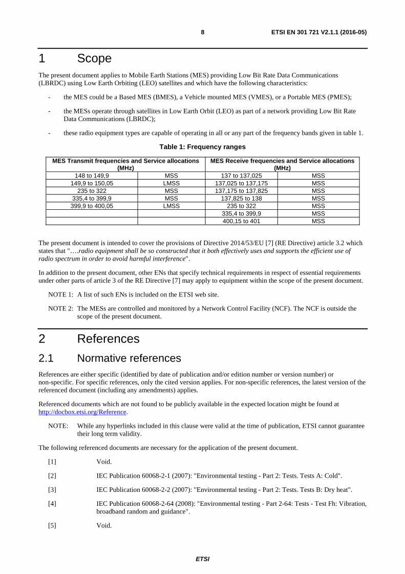
1 Scope The present document applies to Mobile Earth Stations (MES) providing Low Bit Rate Data Communications (LBRDC) using Low Earth Orbiting (LEO) satellites and which have the following characteristics:
- the MES could be a Based MES (BMES), a Vehicle mounted MES (VMES), or a Portable MES (PMES);
- the MESs operate through satellites in Low Earth Orbit (LEO) as part of a network providing Low Bit Rate Data Communications (LBRDC);
- these radio equipment types are capable of operating in all or any part of the frequency bands given in table 1.
Table 1: Frequency ranges
MES Transmit frequencies and Service allocations (MHz)
MES Receive frequencies and Service allocations (MHz)
148 to 149,9 MSS 137 to 137,025 MSS 149,9 to 150,05 LMSS 137,025 to 137,175 MSS
235 to 322 MSS 137,175 to 137,825 MSS 335,4 to 399,9 MSS 137,825 to 138 MSS 399,9 to 400,05 LMSS 235 to 322 MSS
335,4 to 399,9 MSS 400,15 to 401 MSS
The present document is intended to cover the provisions of Directive 2014/53/EU [7] (RE Directive) article 3.2 which states that "….radio equipment shall be so constructed that it both effectively uses and supports the efficient use of radio spectrum in order to avoid harmful interference".
In addition to the present document, other ENs that specify technical requirements in respect of essential requirements under other parts of article 3 of the RE Directive [7] may apply to equipment within the scope of the present document.
NOTE 1: A list of such ENs is included on the ETSI web site.
NOTE 2: The MESs are controlled and monitored by a Network Control Facility (NCF). The NCF is outside the scope of the present document.
2 References
2.1 Normative references References are either specific (identified by date of publication and/or edition number or version number) or non-specific. For specific references, only the cited version applies. For non-specific references, the latest version of the referenced document (including any amendments) applies.
Referenced documents which are not found to be publicly available in the expected location might be found at http://docbox.etsi.org/Reference.
NOTE: While any hyperlinks included in this clause were valid at the time of publication, ETSI cannot guarantee their long term validity.
The following referenced documents are necessary for the application of the present document.
[1] Void.
[2] IEC Publication 60068-2-1 (2007): "Environmental testing - Part 2: Tests. Tests A: Cold".
[3] IEC Publication 60068-2-2 (2007): "Environmental testing - Part 2: Tests. Tests B: Dry heat".
[4] IEC Publication 60068-2-64 (2008): "Environmental testing - Part 2-64: Tests - Test Fh: Vibration, broadband random and guidance".
[5] Void.
ETSI
ETSI EN 301 721 V2.1.1 (2016-05) 9
[6] ETSI EN 300 721 (V1.2.2) (07-1999): "Satellite Earth Stations and Systems (SES); Mobile Earth Stations (MES) providing Low Bit Rate Data Communications (LBRDC) using Low Earth Orbiting (LEO) satellites operating below 1 GHz".
[7] Directive 2014/53/EU of the European Parliament and of the Council of 16 April 2014 on the harmonisation of the laws of the Member States relating to the making available on the market of radio equipment and repealing Directive 1999/5/EC.
2.2 Informative references References are either specific (identified by date of publication and/or edition number or version number) or non-specific. For specific references, only the cited version applies. For non-specific references, the latest version of the referenced document (including any amendments) applies.
NOTE: While any hyperlinks included in this clause were valid at the time of publication, ETSI cannot guarantee their long term validity.
The following referenced documents are not necessary for the application of the present document but they assist the user with regard to a particular subject area.
[i.1] ETSI EG 201 399 (V3.1.1): "Electromagnetic compatibility and Radio spectrum Matters (ERM); A guide to the production of Harmonized Standards for application under the Radio & Telecommunication Terminal Equipment Directive 1999/5/EC (R&TTE) and a first guide on the impact of the Radio Equipment Directive 2014/53/EU (RED) on Harmonized Standards".
[i.2] Commission Implementing Decision C(2015) 5376 final of 4.8.2015 on a standardisation request to the European Committee for Electrotechnical Standardisation and to the European Telecommunications Standards Institute as regards radio equipment in support of Directive 2014/53/EU of the European Parliament and of the Council.
3 Definitions and abbreviations
3.1 Definitions For the purposes of the present document, the terms and definitions given in Directive 2014/53/EU [7] and the following apply:
applicant: manufacturer or his authorized representative within the European Community or the person responsible for placing the apparatus on the market
BMES: MES intended to be installed in a fixed location, and which is powered either by DC or AC supply
carrier-off state: state in which the MES is not transmitting a carrier
carrier-on state: state in which the MES is transmitting a carrier
conducted measurement: measurement of emissions from an antenna port of the MES made by direct wired connection to the port
control channel: channel used to transmit a signal from the satellite containing control information used to command the MES either to enable or disable its transmission
environmental profile: range of environmental conditions under which equipment within the scope of the present document is required to comply with the provisions of the present document
Equivalent Isotropically Radiated Power (EIRP): product of transmitter power and antenna gain, equivalent to an isotropic source radiating uniformly in all directions
host-connected: MES for which connection to or integration with host equipment is necessary to offer functionality
host equipment: equipment which has a complete user functionality when not connected to the MES, and to which the MES provides additional functionality, and to which connection is necessary for the MES to offer functionality
in-band signals: signals which are located in the operating band plus an offset of 10 MHz outside this operating band
ETSI
ETSI EN 301 721 V2.1.1 (2016-05) 10
Installable Equipment (IE), Internally Mounted Equipment (IME) And Externally Mounted Equipment (EME): equipment which is intended to be installed in a vehicle
NOTE: An IE may consist of one or several interconnected modules. The IE is composed of modules intended to be externally mounted as declared by the applicant, and defined as Externally Mounted Equipment (EME) and the remaining modules(s) as Internally Mounted Equipment (IME).
Laboratory Test Equipment (LTE): logical grouping that contains the standard test equipment
Low bit rate data communications: in the present document, bit rates up to 15 kbps
MSS band: continuous range of frequencies allocated by the ITU to the MSS (Mobile Satellite Service)
narrow-band system: one in which the nominal carrier frequency spacing for MESs in the Earth-to-space direction is less than 300 kHz
NCF control message: message, normally originating from a network, to a specified terminal or set of terminals of the network which indicates to the terminal or set of terminals that it/they should carry out some specific action or should enter or maintain some specific state
NOTE: For test purposes NCF control messages may originate from Special Test Equipment (STE).
network control channel: channel by which an MES receives general control information from the NCF
nominated bandwidth: bandwidth of the MES radio frequency transmission nominated by the applicant
NOTE 1: The nominated bandwidth is wide enough to encompass all spectral elements of the transmission which have a level greater than the specified unwanted emissions limits. The nominated bandwidth is wide enough to take account of the transmit carrier frequency stability. The nominated bandwidth is within the MSS transmit frequency band within which the MES operates.
NOTE 2: For FDMA/DCAA systems with a bit rate up to 2,4 kbps the Nominated Bandwidth does not exceed 25 kHz. For FDMA/DCAA systems with a bit rate up above 2,4 kbps the Nominated Bandwidth does not exceed 50 kHz.
Portable MES (PMES): MES intended to be portable, and powered by a stand alone battery, and generally intended to be self-contained and free standing
NOTE: A PMES would normally consist of a single module, but may consist of several interconnected modules. In some cases different specifications apply to PMES and this is noted in the relevant text.
radiated measurement: measurement of an actual radiated field
Special Test Equipment (STE): equipment which permits control of the MES so that the tests required by the present document can be performed
test load: substantially non-reactive, non-radiating power attenuator which is capable of safely dissipating the power from the transmitter(s)
unwanted emissions: emissions falling outside the nominated bandwidth in the carrier-on state, and generated in the carrier-off state
Vehicle Mounted MES (VMES): MES intended to be installed on a vehicle
wideband system: system in which the nominal carrier frequency spacing for MESs in the Earth-to-space direction is equal to or greater than 300 kHz
3.2 Abbreviations For the purposes of the present document, the following abbreviations apply:
AC Alternating Current ASD Acceleration Spectral Density BMES Base MES BW Bandwidth

ETSI
ETSI EN 301 721 V2.1.1 (2016-05) 11
BEL Lower Band Edge of the operating band BEU Upper Band Edge of the operating band CMF Control and Monitoring Function DC Direct Current DCAA Dynamic Channel Activity Assignment DS-SSMA Direct Sequence Spread Spectrum Multiple Access EIRP Equivalent Isotropically Radiated Power EMC Electro-Magnetic Compatibility EME Externally Mounted Equipment EUT Equipment Under Test FDMA Frequency Division Multiple Access IE Installable Equipment IEC International Electrotechnical Commission/Committee IME Internally Mounted Equipment kbps kilobits per second LBRDC Low Bit Rate Data Communications LMSS Land Mobile Satellite Service LTE Laboratory Test Equipment LTE Long Term Evolution MES Mobile Earth Station MIC MES Identification Code MSS Mobile Satellite Service NCF Network Control Facility PMES Portable MES ppm parts per million R&TTE Radio and Telecommunications Terminal Equipment RAS Radio Astronomy Service RE Radio Equipment RED Radio Equipment Directive RF Radio Frequency STE Special Test Equipment VMES Vehicle Mounted MES
4 Technical requirements specifications
4.1 Environmental profile
4.1.1 General
The technical requirements of the present document apply under the environmental profile specified below for operation of the equipment. The equipment shall comply with all the technical requirements of the present document at all times when operating within the boundary limits of the specified operational environmental profile.
4.1.2 Temperature
The MES shall fulfil all the requirements in the full temperature ranges of:
-10 °C to +55 °C;
taken from IEC publications 60068-2-1 [2] and 60068-2-2 [3].
For MESs expected to operate in an environment outside this temperature range the applicant will take the necessary actions to ensure proper operation.
4.1.3 Voltage
The applicant shall declare the nominal, lower and the higher extreme voltages.
The MES shall fulfil all the requirements in the full voltage range between the extreme voltages.

ETSI
ETSI EN 301 721 V2.1.1 (2016-05) 12
4.1.4 Vibration
The MES shall fulfil all the requirements when vibrated at the frequency/amplitudes given in table 2.
Table 2: Vibration characteristics
Frequency range ASD (Acceleration Spectral Density) random vibration 5 Hz to 20 Hz 0,96 m2/s3 (+0/-5 %)
20 Hz to 500 Hz 0,96 m2/s3 (+0/-5 %) at 20 Hz, thereafter -3 dB/Octave (+0/-5 %) (taken from IEC Publication 60068-2-64 [4])
4.2 Conformance requirements
4.2.1 Unwanted emission outside the bands 148 MHz to 150,05 MHz, 235 MHz to 322 MHz, 335,4 MHz to 399,9 MHz and 399,9 MHz to 400,05 MHz
4.2.1.1 Justification
To protect other terrestrial services, space radio communications services and the radio astronomy services from emissions caused by MESs outside the bands 148 MHz to 150,05 MHz, 235 MHz to 322 MHz, 335,4 MHz to 399,9 MHz and 399,9 MHz to 400,05 MHz.
4.2.1.2 Technical requirements
The unwanted emissions from the MES outside the uplink bands 148 MHz to 150,05 MHz, 235 MHz to 322 MHz, 335,4 MHz to 399,9 MHz and 399,9 MHz to 400,05 MHz, within which the MES is designed to operate, shall not exceed the limits shown in tables 3, 4 and 5.
Table 3A: Unwanted emissions outside the operational band 148 MHz to 150,05 MHz, 235 MHz to 322 MHz, 335,4 MHz to 399,9 MHz and 399,9 MHz to 400,05 MHz
for FDMA MESs with a bit rate up to 2,4 kbps
Frequency
Maximum EIRP density (dBpW)
Measurement
(MHz) FDMA Bandwidth 0,1 to 148 54 100 kHz
150,05 to 235 54 100 kHz 322 to 335,4 54 100 kHz
400,05 to 1 000 54 100 kHz 1 000 to 1 559 60 1 MHz
1 559 to 1 626,5 50 1 MHz 1 626,5 to 12 750 60 1 MHz

ETSI
ETSI EN 301 721 V2.1.1 (2016-05) 13
Table 3B: Unwanted emissions outside the operational band 148 MHz to 150,05 MHz, 235 MHz to 322 MHz, 335,4 MHz to 399,9 MHz and 399,9 MHz to 400,05 MHz
for FDMA MESs with a bit rate above 2,4 kbps
Frequency
Maximum EIRP density (dBpW)
Measurement
(MHz) FDMA Bandwidth 0,1 to 147,900 54 100 kHz
147,9 to 147,950 54 to 85 (note 1) 100 kHz 147,950 to 148 85 (note 2) 100 kHz
150,05 to 150,100 85 (note 2) 100 kHz 150,100 to 150,150 85 to 54 (note 1) 100 kHz
150,150 to 235 54 100 kHz 322 to 335,4 54 100 kHz
400,05 to 1 000 54 100 kHz 1 000 to 1 559 60 1 MHz
1 559 to 1 626,5 50 1 MHz 1 626,5 to 12 750 60 1 MHz
NOTE 1: Linearly interpolated in dBpW vs. frequency. NOTE 2: At no time during the measurement is the measurement bandwidth permitted to
encroach into the operational band.
Table 4: Unwanted emissions for DS-SSMA MESs outside the operational band 148 MHz to 150,05 MHz
Frequency
Maximum EIRP density (dBpW)
Measurement
(MHz) DS-SSMA bandwidth 0,1 to 146 54 100 kHz
146 to 147,5 70 100 kHz 147,5 to 148 70 to 105 (see note) 100 kHz
150,05 to 151,15 70 100 kHz 151,15 to 1 000 54 100 kHz 1 000 to 1 559 60 1 MHz
1 559 to 1 626,5 50 1 MHz 1 626,5 to 12 750 60 1 MHz
NOTE: Linearly interpolated in dBpW vs. Frequency.
Table 5: Unwanted emissions for DS-SSMA MESs outside the operational bands 235 MHz to 322 MHz, 335,4 MHz to 399,9 MHz and 399,9 MHz to 400,05 MHz
Frequency (MHz)
Maximum EIRP density (dBpW)
Measuring bandwidth
0,1 to 30 54 100 kHz 30 to 235 54 100 kHz
322 to 335,4 54 100 kHz 400,05 to 1 000 54 100 kHz 1 000 to 1 559 60 1 MHz
1 559 to 1 626,5 50 1 MHz 1 626,5 to 12 750 60 1 MHz
In tables 3, 4 and 5, whenever a change of limit between adjacent frequency bands occurs, the lower of the two limits shall apply at the transition frequency.
The technical requirements apply for the full range of environmental conditions corresponding to the type of equipment as specified in clause 5.1.2 (see clause 5.2.2).
4.2.1.3 Conformance test
This test shall be carried out for two MES frequencies if available, the minimum and the maximum MES transmit frequencies for which the MES is designed to operate, as specified by the applicant.
ETSI
ETSI EN 301 721 V2.1.1 (2016-05) 14
The environmental test conditions are given in clause 5.1.2.
For each test, the MES shall be set to transmit (carrier-on state) on one of the specified transmitting frequencies to be tested at its maximum power for that transmit frequency, by means of the STE or by another test facility provided by the applicant.
If there is a handover function in the MES (to allow change of frequency channel during a transmission), this function shall be disabled.
The transmitted carrier shall be modulated by a pseudorandom bit sequence generated by the MES or by the STE. For a MES operational in short burst mode, this sequence will be of length compatible with the maximum burst length duration. Otherwise the transmitted carrier shall be modulated by a test signal at maximum rate as specified in clause 5.2.4.2.3.
In the test equipment, the spectrum analyser noise floor shall be at least 6 dB below the appropriate limits given in tables 3, 4 and 5.
The measurements are performed with the radiated or with the conducted method according to the cases defined in clause 5.2.4.4.
For measurements of radiated unwanted emissions, clause 5.2.6 applies.
For measurements of conducted unwanted emissions, clause 5.2.7 applies.
4.2.1.4 Test Condition
The spectrum analyser shall be set in sweep mode and shall be operated under the following conditions:
• frequency sweep: as required for frequency range to be assessed;
• resolution bandwidth: measurement bandwidth specified in tables 3, 4 and 5;
• video bandwidth: equal to the measurement bandwidth;
• averaging: yes;
• peak hold: no.
The measurement time shall be such that the difference of the measured levels, averaged over subsequent measurement samples, is less than 1 dB, or a measurement time of 100 ms may be used if the measured values comply with the applicable limits.
For a MES operating in a non-continuous carrier mode, the measurement shall be performed over the active part of the transmitted bursts. The total sample time used for measurement shall be not less than 40 % of the duration of the active part of the transmitted burst. The measurement shall be made over the random part of the burst, excluding any preambles or synchronization sequences. These measurements may be performed with the MES operating in continuous mode if the MES is capable of such operation.
4.2.1.5 Test requirements
For measurements of radiated unwanted emissions of the MES, the measured values shall not exceed the limits given in tables 3, 4 and 5, as applicable.
For measurements of conducted unwanted emissions of the MES, the measured values plus the declared maximum antenna gain (or the declared antenna gain at the frequency of the measured spurious emission – in accordance with clause 5.2.2) shall in no case exceed the limits given in tables 3, 4 and 5.
Verification:
By measurement of unwanted emissions generated by an operating MES.
All RF tests in this clause shall be carried out at environmental conditions as specified in clause 5.1.2.
All tests in the carrier-on state shall be undertaken with the transmitter operating at full power and with the maximum transmit burst rate where applicable.

ETSI
ETSI EN 301 721 V2.1.1 (2016-05) 15
To enable the performance tests to be carried out, the use of Special Test Equipment (STE), supplied by the applicant, may be necessary. Since this STE will be specific for the particular system, it is not possible to provide detailed specifications in the present document.
However, the following baseline is provided:
- if the MES requires to receive a modulated carrier from the satellite in order to transmit, then special test arrangements are required to simulate the satellite signal, thus enabling the MES to transmit allowing measurement of transmission parameters;
- any specification of these special test arrangements which may have direct or indirect effects on any requirement or recommendation of the present document shall be clearly stated by the applicant.
4.2.2 Unwanted emission within the bands 148 MHz to 150,05 MHz, 235 MHz to 322 MHz, 335,4 MHz to 399,9 MHz and 399,9 MHz to 400,05 MHz
4.2.2.1 Justification
To protect other terrestrial and space radio communications services operating in the above frequency bands.
4.2.2.2 Technical requirements
For each transmit band 148 MHz to 150,05 MHz, 235 MHz to 322 MHz, 335,4 MHz to 399,9 MHz and 399,9 MHz to 400,05 MHz, within which the MES is designed to operate, the unwanted emissions EIRP in any 4 kHz band within that transmit band and outside the nominated bandwidth shall in the carrier-on state not exceed the limits given in table 6.
Table 6: Unwanted emissions EIRP within the operational bands but outside the nominated bandwidth
Offset from the edge of the nominated bandwidth Maximum EIRP density (dBpW/4 kHz) DS-SSMA FDMA with bit rate
up to 2,4 kbps FDMA with bit rate up above 2,4 kbps
0 to 25 % of the nominated bandwidth 90 to 56 (note) 70 85 to 70 (note) 25 to 50 % of the nominated bandwidth 70
50 % to 250 % of the nominated bandwidth 56 65 65 > 250 % of the nominated bandwidth up to 5 MHz 56 65 65 if applicable, to the edge of the operational band 56 65 65
NOTE: Linearly interpolated in dBpW vs. Frequency.
The technical requirements apply for the full range of environmental conditions corresponding to the type of equipment as specified in clause 5.1.2 (see clause 5.2.2).
4.2.2.3 Conformance test
This test shall be carried out for two MES frequencies, if available, the minimum and the maximum transmit frequency for which the MES is designed to operate, as specified by the applicant.
Two additional transmit frequencies shall be tested if available. These frequencies shall be equally spaced between the lowest and highest transmit frequencies. The transmit frequencies used for the test shall be entered in the test report.
The environmental test conditions are given in clause 5.1.2.
For each test, the MES shall be set to transmit (carrier-on state) on one of the specified transmit frequencies to be tested, at its maximum power for that transmit frequency, by means of the STE or by another test facility provided by the applicant.
If there is a handover function in the MES (to allow change of frequency channel during a transmission), this function shall be disabled.
The transmitted carrier shall be modulated by a test signal at maximum rate as specified in clause 5.2.4.2.3.
ETSI
ETSI EN 301 721 V2.1.1 (2016-05) 16
In the test equipment, the spectrum analyser noise floor shall be at least 6 dB below the appropriate limits given in table 6 as applicable.
The measurements are performed with the radiated or with the conducted method according to the cases defined in clause 5.2.4.4.
For measurements of radiated unwanted emissions, clause 5.2.6 applies.
For measurements of conducted unwanted emissions, clause 5.2.7 applies.
4.2.2.4 Test condition
The spectrum analyser shall be set in sweep mode and shall be operated under the following conditions:
• frequency sweep: as required for frequency range to be assessed;
• resolution bandwidth: measurement bandwidth specified in clause 4.2.2.2;
• video bandwidth: equal to the measurement bandwidth;
• averaging: yes;
• peak hold: no.
The measurement time shall be such that the difference of the measured levels, averaged over subsequent measurement samples, is less than 1 dB, or a measurement time of 100 ms may be used if the measured values comply with the applicable limits.
For a MES operating in a non-continuous carrier mode, the measurement shall be performed over the active part of the transmitted bursts. The total sample time used for measurement shall be not less than 40 % of the duration of the active part of the transmitted burst. The measurement shall be made over the random part of the burst, excluding any preambles or synchronization sequences.
4.2.2.5 Test requirements
For measurements of radiated unwanted emissions of the MES, the measured values shall in no case exceed the limits given in table 6 as applicable.
For measurements of conducted unwanted emissions, the measured values plus the maximum antenna gain shall in no case exceed the limits given in table 6 as applicable.
4.2.3 EIRP density within the operational band
4.2.3.1 Justification
To protect other services which use the same frequency band.
4.2.3.2 Technical requirements
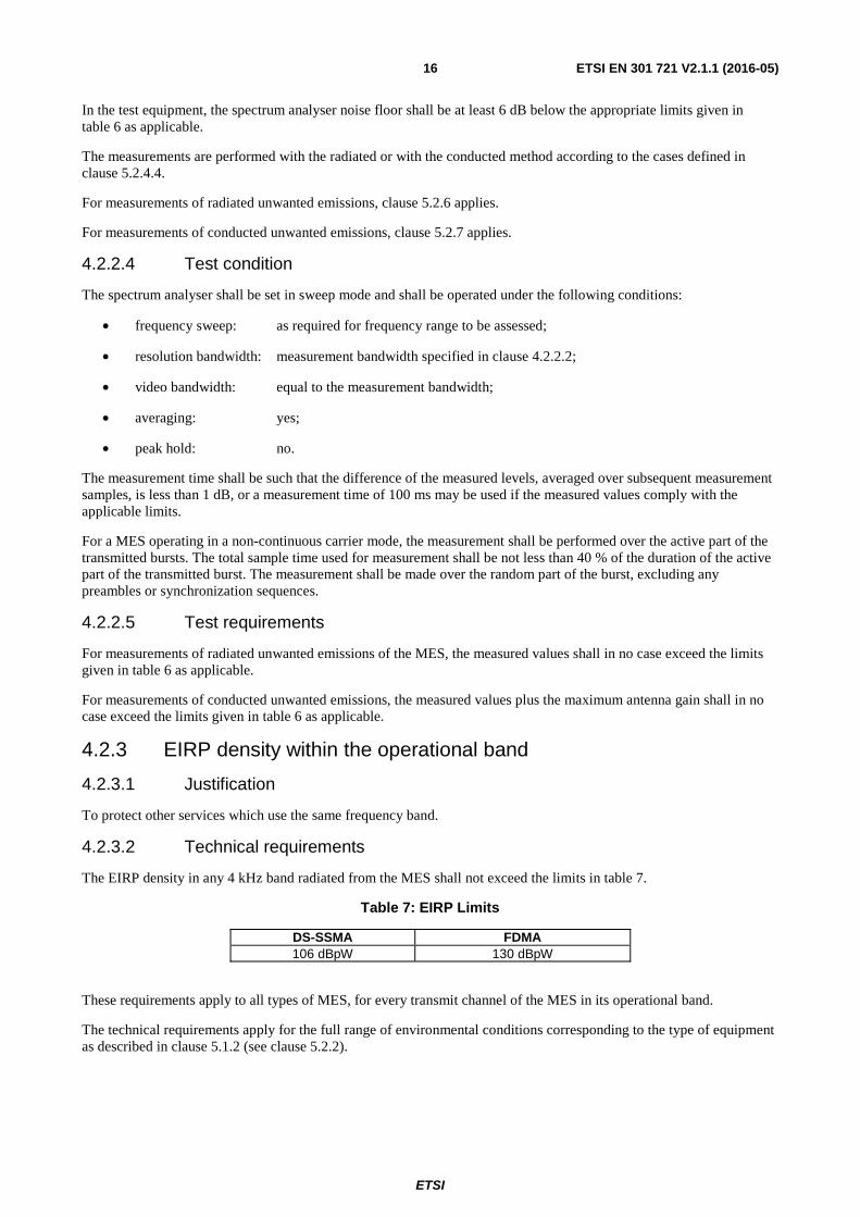
The EIRP density in any 4 kHz band radiated from the MES shall not exceed the limits in table 7.
Table 7: EIRP Limits
DS-SSMA FDMA 106 dBpW 130 dBpW
These requirements apply to all types of MES, for every transmit channel of the MES in its operational band.
The technical requirements apply for the full range of environmental conditions corresponding to the type of equipment as described in clause 5.1.2 (see clause 5.2.2).
ETSI
ETSI EN 301 721 V2.1.1 (2016-05) 17
4.2.3.3 Conformance test
If available minimum two MES transmit frequencies shall be used for this test. These frequencies shall be the minimum and the maximum frequencies of the band for which the MES is designed to operate, as specified by the applicant. Where available, the EIRP density shall also be tested at two additional transmit frequencies. These frequencies shall be equally spaced between the minimum and maximum frequencies. The measured EIRP densities and the corresponding transmit frequencies used for the test shall be entered in the test report.
The environmental test conditions are given in clause 5.1.2.
For each test, the MES shall be set to transmit (carrier-on state) at its maximum power-on the specified transmitting frequency to be tested, by means of the STE or by another test facility provided by the applicant.
If there is a handover function in the MES (to allow change of frequency channel during a transmission), this function shall be disabled.
The transmitted carrier shall be modulated by a test signal at maximum rate as specified in clause 5.2.4.2.3.
In the test equipment, the spectrum analyser noise floor shall be at least 6 dB below the appropriate values to be measured.
The measurements are performed with the conducted or with the radiated method according to the cases defined in clause 5.2.4.4.
For radiated measurements of transmitted EIRP density, clause 5.2.6 applies.
For assessment of transmitted EIRP density by conducted measurements, clause 5.2.7 applies.
4.2.3.4 Test condition
The spectrum analyser shall be set in sweep mode and shall be operated under the following conditions:
• frequency sweep: from the lower to the upper limits of the nominated bandwidth of the transmit channel under test;
• resolution bandwidth: measurement bandwidth specified in clause 4.2.3.2;
• video bandwidth: equal to the measurement bandwidth;
• averaging: yes;
• peak hold: no.
The measurement time shall be such that the difference of the measured levels, averaged over subsequent measurement samples, is less than 1 dB, or a measurement time of 100 ms may be used if the measured values comply with the applicable limits. These measurements may be performed with the MES operating in continuous mode if the MES is capable of such operation.
Alternatively, a power meter may be used with a correction factor to account for the duty cycle.
4.2.3.5 Test requirements
For measurements of radiated EIRP, the measured values shall not exceed the appropriate values given in clause 4.2.3.2, for each specific frequency sub-band and operating condition for which the limit applies, as specified by the applicant.
For assessment of EIRP by conducted measurement, the measured values plus the maximum antenna gain shall not exceed the appropriate values given in clause 4.2.3.2, for each specific frequency band and operating condition for which the limit applies, as specified by the applicant.
4.2.4 Unwanted emissions in carrier-off state
4.2.4.1 Justification
To protect other radio services and systems from unwanted emissions caused by MESs in the carrier-off state.
ETSI
ETSI EN 301 721 V2.1.1 (2016-05) 18
4.2.4.2 Technical requirements
The maximum EIRP of the unwanted emissions from the MESs in the carrier-off state shall not exceed 33 dBpW in any 100 kHz.
The technical requirements apply for the full range of environmental conditions corresponding to the type of equipment as specified in clause 5.1.2 (see clause 5.2.2).
4.2.4.3 Conformance test
The MES shall be in the power-on state and set in a non-transmitting (carrier-off state) mode.
If there is a periodic automatic transmission of bursts (e.g. for location updating), the STE shall provide a means to inhibit it, or to trigger the measurement in order to analyse only the non-transmitting periods.
The environmental test conditions are given in clause 5.1.2.
In the test equipment, the spectrum analyser noise floor shall be at least 6 dB below the appropriate limits given in clause 4.2.4.2.
The measurements are performed with the radiated or with the conducted method according to the cases defined in clause 5.2.4.4.
For measurements of radiated unwanted emissions, clause 5.2.6 applies as modified by the spectrum analyser operating conditions specified in clause 4.2.4.4.
For measurements of conducted unwanted emissions, clause 5.2.7 applies as modified by the spectrum analyser operating conditions specified in clause 4.2.4.4.
4.2.4.4 Test condition
The spectrum analyser shall be set in sweep mode and shall be operated under the following conditions:
• frequency sweep: as required for frequency range to be assessed;
• resolution bandwidth: 100 kHz;
• video bandwidth: at least 3 times the measurement bandwidth;
• averaging: no;
• peak hold: yes.
The sweep time shall be the shortest possible time consistent with proper calibration and ease of operation.
The spectrum analyser shall be stepped over the frequency ranges specified.
4.2.4.5 Test requirements
For measurements of radiated unwanted emissions of the MES, the measured values shall in no case exceed the limits given in clause 4.2.4.2.
For measurements of conducted unwanted emissions of the MES, the measured values plus the maximum antenna gain shall in no case exceed the limits given in clause 4.2.4.2.
4.2.5 MES Control and Monitoring Functions (CMF)
4.2.5.1 Justification
To protect radio services and systems from uncontrolled RF transmissions from the MES.
ETSI
ETSI EN 301 721 V2.1.1 (2016-05) 19
4.2.5.2 Special Test Equipment (STE)
Many of the tests in this clause require that the MES be situated in an environment where receipt of a network control channel and of NCF commands is ensured. This will require the provision of STE (see clause 5.2.4.2). This STE shall provide the means to generate and to communicate to the MES, either radiated via its antenna or conducted via direct connection to its antenna port, the network control channel and the required NCF commands. The STE shall also provide means to interface the test equipment with the MES for the purpose of monitoring the MES responses.
4.2.5.3 Technical requirements
4.2.5.3.1 Self-monitoring functions
4.2.5.3.1.1 Processor monitoring
The MES shall incorporate a processor monitoring function for each of its processors involved in the manipulation of traffic and in control and monitoring functions.
The processor monitoring function shall detect failure of the processor hardware and software.
While the MES is in an active powered state not later than 1 s after any detectable fault condition occurs, the transmissions shall be suppressed (carrier-off state) until the processor monitoring function has determined that all fault conditions have been cleared.
The fault conditions which cause transmission shutdown shall be specified and declared by the applicant.
The technical requirements apply for the environmental conditions as specified in clause 5.1.2 (see clause 5.2.2).
4.2.5.3.1.2 Transmit frequency generation sub-system monitoring
The MES shall incorporate a transmit frequency generation sub-system monitoring function.
If a failure of the transmit frequency generation sub-system for a cumulative period of more than 5 seconds occurs, the transmissions shall be suppressed (carrier-off state) until the transmit frequency generation sub-system monitoring function has determined that all fault conditions have been cleared.
The fault conditions which cause transmission shutdown shall be specified and declared by the applicant.
The technical requirements apply for the environmental conditions as specified in clause 5.1.2 (see clause 5.2.2).
4.2.5.3.1.3 Conformance test
As it is considered impracticable to artificially induce processor or transmit frequency generation sub-system faults in an MES, no test is given for these sub-system monitoring functions.
4.2.5.3.2 Network control authorization and reception - Network control authorization
4.2.5.3.2.1 Requirements
Following POWER-ON the MES shall enter a controlled, non-transmitting state (carrier-off state). This state shall be maintained whilst the MES is not synchronized with the appropriate network control channel(s).
Without synchronizing to the appropriate network control channel(s), it shall not be possible to initiate carrier-on state.
Within 30 s of having lost the appropriate network control channel(s) the MES shall suppress transmissions (carrier-off state).
The technical requirements apply for the environmental conditions as specified in clause 5.1.2 (see clause 5.2.2).
4.2.5.3.2.2 Conformance test
The MES shall be cycled through its power-on and power-off states. Attempts shall be made to initiate transmissions using normal operational procedures. The transmitting state of the MES shall be monitored to ensure compliance with the test requirements.
The environmental test conditions are given in clause 5.1.2.
ETSI
ETSI EN 301 721 V2.1.1 (2016-05) 20
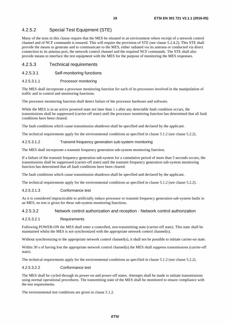
4.2.5.3.2.3 Test procedure and requirements
Table 8: Network control authorization - Test procedure and requirements
Step Procedure Requirements The MES shall be situated in an environment where receipt of the appropriate network control channel(s) is
controlled by the test facility. 1 The MES shall be in a power-off state, situated such that
it is not in receipt of a network control channel. The MES shall remain in power-off state.
2 The MES shall be powered-on. No transmissions shall occur (carrier-off state). 3 An attempt shall be made, using normal operational
procedures, to initiate a transmission. No transmissions shall occur (carrier-off state).
4 A network control channel shall be activated and a transmission shall be initiated using normal operational procedures.
The MES shall transmit (carrier-on state).
5 The network control channel shall then be deactivated. Within 30 s the MES transmissions shall cease (carrier-off state).
6 An attempt shall be made, using normal operational procedures, to initiate a transmission.
No transmissions shall occur (carrier-off state).
7 The network control channel shall be reactivated and a transmission shall be initiated using normal operational procedures.
The MES shall be transmitting (carrier-on state).
Throughout this procedure, the transmission state of the MES shall be monitored.
4.2.5.3.3 Network control authorization and reception - Network control reception
4.2.5.3.3.1 Transmission disable/enable
A MES which is transmitting (carrier-on state) shall not continue transmissions for a period of time longer than 1 second after receipt of a transmission disable command from its NCF. After ceasing transmissions the MES shall then not transmit until it receives a transmission enable command from its NCF.
A MES which is powered-on but not transmitting (carrier-off state) when it is in receipt of a transmission disable command from its NCF shall then not transmit until it receives a transmission enable command from its NCF.
The technical requirements apply for the environmental conditions as specified in clause 5.1.2 (see clause 5.2.2).
4.2.5.3.3.2 Conformance test
The MES shall be sent transmission enable and transmission disable commands. Attempts shall be made to initiate transmissions using normal operational procedures. The transmitting state of the MES shall be monitored to ensure compliance with the test requirements.
The environmental test conditions are given in clause 5.1.2.
ETSI
ETSI EN 301 721 V2.1.1 (2016-05) 21
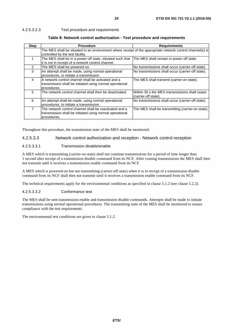
4.2.5.3.3.3 Test procedure and requirements
Table 9: Network control reception - Test procedure and requirements
Step Procedure Requirements The MES shall be situated in an environment where receipt of the appropriate network control channel(s) and
NCF commands are controlled by the test facility. 1 A network control channel shall be activated, the MES
shall be powered-on, and a transmission shall be initiated using normal operational procedures.
The MES transmit (carrier-on state).
2 A NCF command to disable transmissions shall be sent to the MES.
Within 1 s of receipt of the NCF command to disable transmissions, MES transmissions shall cease (carrier-off state).
3 Whilst the disable command applies an attempt shall be made to initiate a transmission using normal operational procedures.
No transmissions shall occur (carrier-off state).
4 An NCF command to enable transmissions shall be sent to the MES and a transmission shall be initiated using normal operational procedures.
The MES shall be transmitting (carrier-on state).
5 The MES shall be set in carrier-off state mode, a NCF command to disable transmissions shall be sent to the MES.
No transmissions shall occur (carrier-off state).
6 Whilst the disable command applies an attempt shall be made to initiate a transmission using normal operational procedures.
No transmissions shall occur (carrier-off state).
7 A NCF command to enable transmissions shall be sent to the MES and a transmission shall be initiated using normal operational procedures.
The MES shall be transmitting (carrier-on state).
Throughout this procedure, the transmission state of the MES shall be monitored.
4.2.5.3.4 Transmit frequency control
4.2.5.3.4.1 Requirements
The MES shall set the carrier frequency of its transmission according to the command of the NCF. The carrier frequency has to be controlled such, that the entire nominated bandwidth of the terminal falls completely within the operational frequency band(s) specified and declared by the applicant.
The technical requirements apply for the environmental conditions as specified in clause 5.1.2 (see clause 5.2.2).
4.2.5.3.4.2 Conformance test
The nominated bandwidth of the MES shall be monitored relative to the carrier frequency commanded, and relative to the operational frequency bands for the MES specified by the applicant.
The environmental test conditions are given in clause 5.1.2.
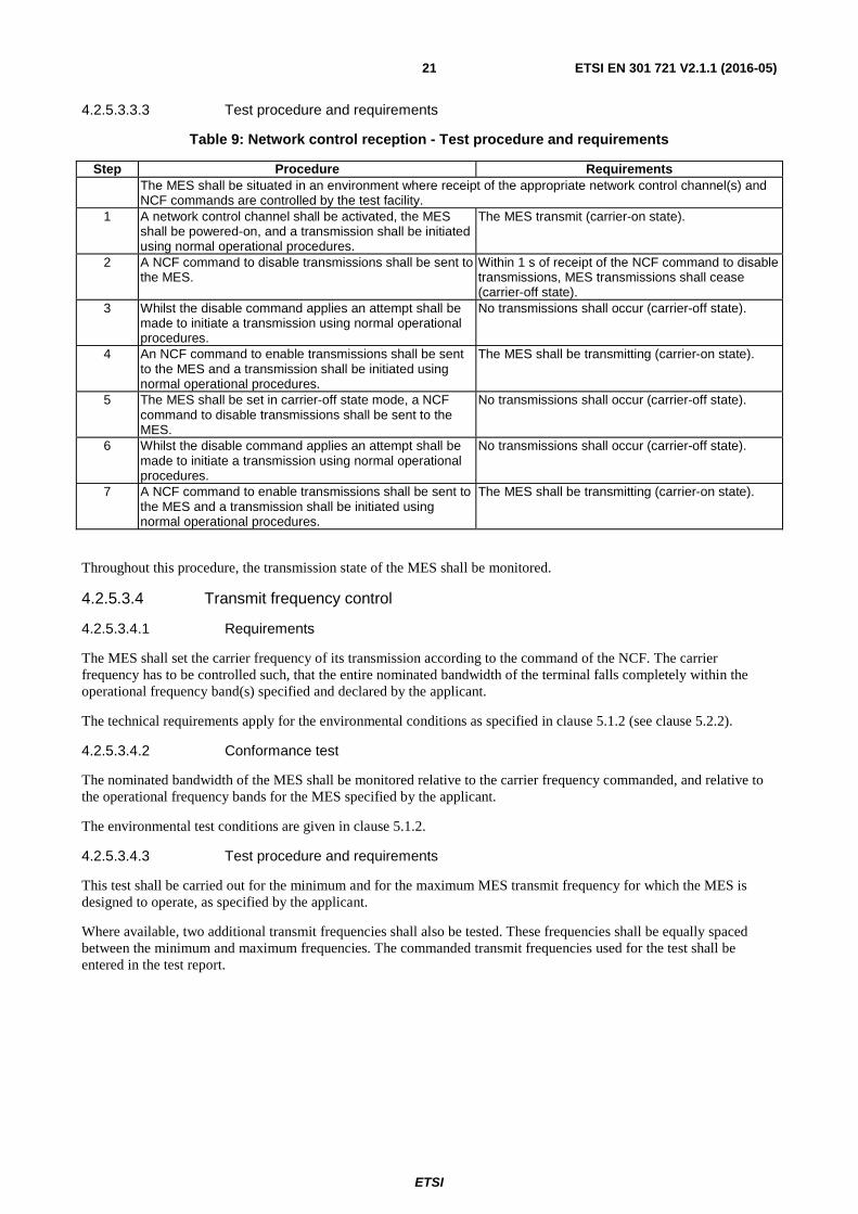
4.2.5.3.4.3 Test procedure and requirements
This test shall be carried out for the minimum and for the maximum MES transmit frequency for which the MES is designed to operate, as specified by the applicant.
Where available, two additional transmit frequencies shall also be tested. These frequencies shall be equally spaced between the minimum and maximum frequencies. The commanded transmit frequencies used for the test shall be entered in the test report.
ETSI
ETSI EN 301 721 V2.1.1 (2016-05) 22
Table 10: Transmit frequency control - Test procedure and requirements
Step Procedure Requirements The MES shall be situated in an environment where receipt of a network control channel and of NCF
commands is ensured. 1 A network control channel shall be activated with the MES
powered-on.
2 The MES shall be set to transmit on the frequency to be tested.
The entire nominated bandwidth for each transmit frequency tested shall be contained completely within the operational frequency band(s) specified by the applicant.
3 The test shall be repeated for the other transmit frequencies to be tested.
The carrier mask for the transmit frequency under test shall be monitored on a spectrum analyser, using the procedures given in clause 4.2.2.4.
4.2.6 Equipment identity
4.2.6.1 Justification
To identify MESs causing uncontrolled RF transmissions.
4.2.6.2 Technical requirements
Each MES shall have a unique MES Identification Code (MIC) within its network.
It shall not be possible for the user to alter the MIC using any normally accessible procedure.
The technical requirements apply for the environmental conditions as specified in clause 5.1.2 (see clause 5.2.2).
4.2.6.3 Conformance test
It is impracticable to test that each MES has a unique MES identification code (MIC) within its network, and that it is not possible for the user to alter the MIC using any normally accessible procedure. Consequently, no tests are given for these requirements.
The transmissions of the MES in response to an NCF command to send its identification code shall be monitored and the identification code received shall be verified.
The environmental test conditions are given in clause 5.1.2.
4.2.6.4 Test procedure
The MES shall be situated in an environment where receipt of a network control channel and of NCF commands is ensured.
a) A network control channel shall be activated and the MES powered-on.
b) An appropriate NCF control message shall be sent, commanding the MES to transmit its identification code.
c) The message sent by the MES shall be analysed.
4.2.6.5 Test requirements
The MES identification code in the message sent in step c) of clause 4.2.6.4 shall be verified against that supplied by the applicant for the MES under test.

ETSI
ETSI EN 301 721 V2.1.1 (2016-05) 23
4.2.7 Protection of the Radio Astronomy Service (RAS) from emissions produced by the MES in the bands 150,05 MHz to 153 MHz, 322 MHz to 328,6 MHz and 406,1 MHz to 410 MHz
4.2.7.1 Justification
To protect the radio astronomy observations taking place in the frequency bands 150,05 MHz to 153 MHz, 322 MHz to 328,6 MHz and 406,1 MHz to 410 MHz.
4.2.7.2 Technical requirements
The MES shall provide means to reduce unwanted emissions in the adjacent bands 150,05 MHz to 153 MHz, 322 MHz to 328,6 MHz and 406,1 MHz to 410 MHz.
Covered by clause 4.2.5.3.3.1.
4.2.7.3 Conformance test
Covered by clause 4.2.5.
4.2.7.4 Test procedure
Covered by clause 4.2.5.
4.2.7.5 Test requirement
Covered by clause 4.2.5.
4.2.8 Receiver Performance Requirements
4.2.8.1 General
This clause shall apply for all MES operating in the frequency bands as listed in table 1.
4.2.8.2 Receiver Adjacent Channel Selectivity
4.2.8.2.1 Justification
To enable reception of a wanted signal in the presence of other signals in the adjacent channel.
Adjacent channel selectivity is a measure of a receiver's ability to receive a signal at its assigned channel frequency in the presence of a signal in the adjacent channel at a given frequency offset from the centre frequency of the assigned channel.
4.2.8.2.2 Technical requirements
The frequency offset and relative power level of the adjacent signal compared to the wanted signal shall take the values given in table 11. The adjacent signal shall occupy the same bandwidth as the wanted signal where BW is the wanted signal occupied bandwidth. There shall be no more than 0,5 dB degradation in the receiver signal to noise ratio under these conditions.
Table 11: Adjacent Channel frequency and power level
Signal Centre frequency offset from wanted
signal
Power level relative to wanted signal
Adjacent signal BW 12 dB
4.2.8.2.3 Conformance test
Covered by clause 5.2.8.
ETSI
ETSI EN 301 721 V2.1.1 (2016-05) 24
4.2.8.2.4 Test procedure
Covered by clause 5.2.8.3.
4.2.8.3 Receiver Blocking Characteristics
4.2.8.3.1 Justification
To prevent high power signals outside the receive frequency band from blocking the reception of signals inside the receive frequency band.
The blocking characteristic is a measure of the receiver's ability to receive a wanted signal at its assigned channel frequency in the presence of an unwanted interferer on frequencies other than those of the spurious response or the adjacent channels, without this unwanted input signal causing a degradation of the performance of the receiver beyond a specified limit. Receiver blocking is specified for in-band signals. In-band signals are signals in the range:
• BEL -10MHz to BEU +10 MHz, where BEL and BEU are the lower and upper edges of the operating bands respectively.
4.2.8.3.2 Technical requirements
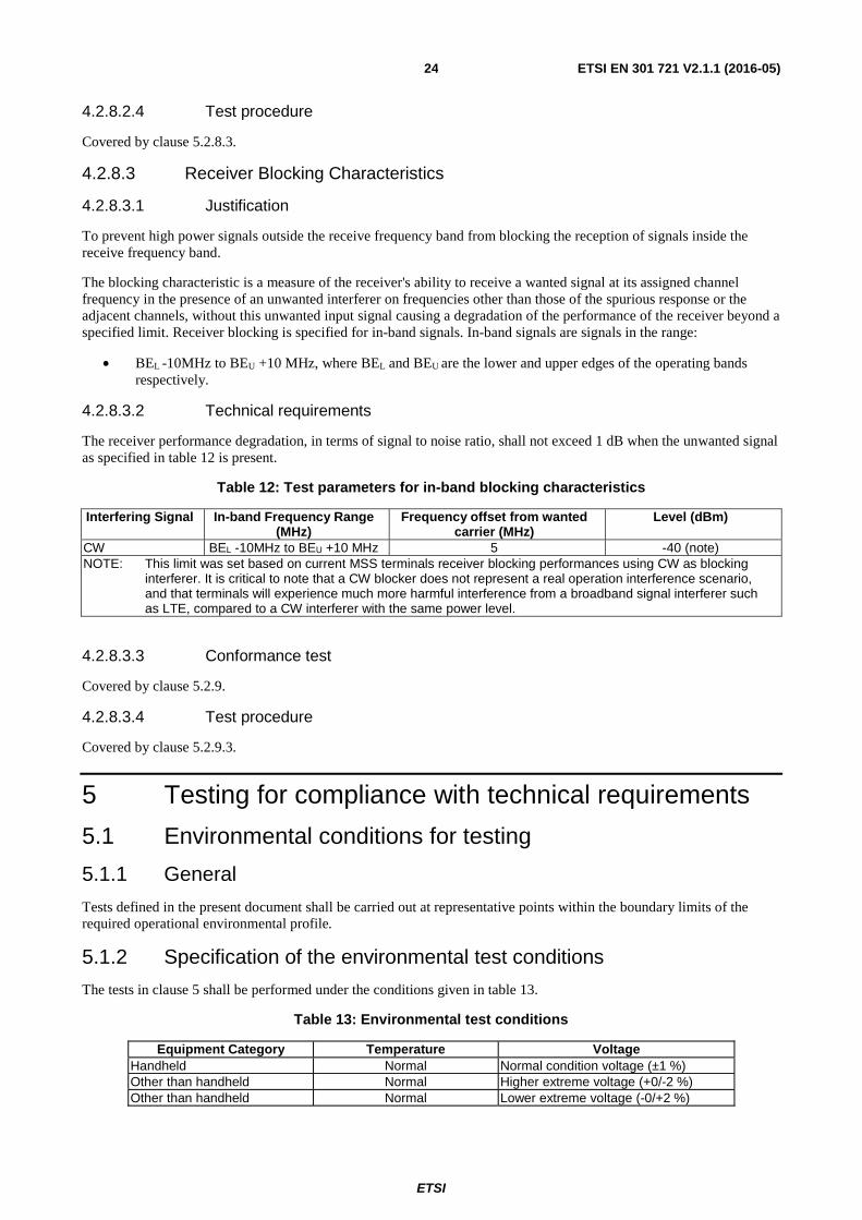
The receiver performance degradation, in terms of signal to noise ratio, shall not exceed 1 dB when the unwanted signal as specified in table 12 is present.
Table 12: Test parameters for in-band blocking characteristics
Interfering Signal In-band Frequency Range (MHz)
Frequency offset from wanted carrier (MHz)
Level (dBm)
CW BEL -10MHz to BEU +10 MHz 5 -40 (note) NOTE: This limit was set based on current MSS terminals receiver blocking performances using CW as blocking
interferer. It is critical to note that a CW blocker does not represent a real operation interference scenario, and that terminals will experience much more harmful interference from a broadband signal interferer such as LTE, compared to a CW interferer with the same power level.
4.2.8.3.3 Conformance test
Covered by clause 5.2.9.
4.2.8.3.4 Test procedure
Covered by clause 5.2.9.3.
5 Testing for compliance with technical requirements
5.1 Environmental conditions for testing
5.1.1 General
Tests defined in the present document shall be carried out at representative points within the boundary limits of the required operational environmental profile.
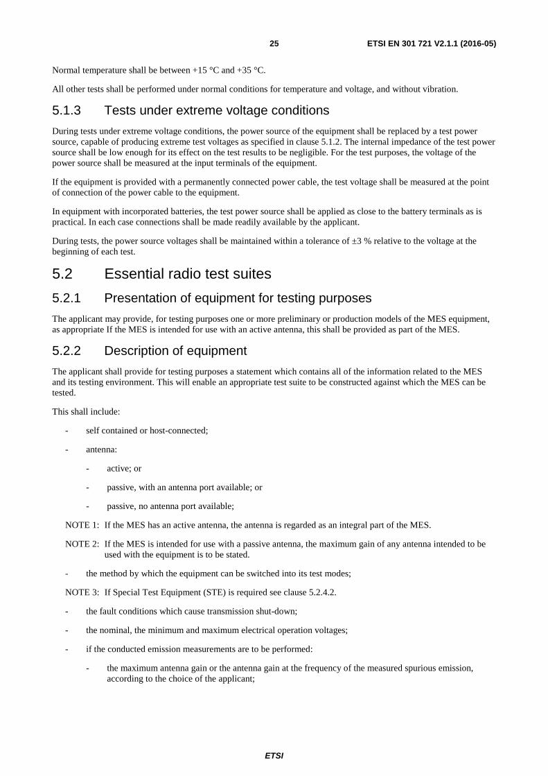
5.1.2 Specification of the environmental test conditions
The tests in clause 5 shall be performed under the conditions given in table 13.
Table 13: Environmental test conditions
Equipment Category Temperature Voltage Handheld Normal Normal condition voltage (±1 %) Other than handheld Normal Higher extreme voltage (+0/-2 %) Other than handheld Normal Lower extreme voltage (-0/+2 %)
ETSI
ETSI EN 301 721 V2.1.1 (2016-05) 25
Normal temperature shall be between +15 °C and +35 °C.
All other tests shall be performed under normal conditions for temperature and voltage, and without vibration.
5.1.3 Tests under extreme voltage conditions
During tests under extreme voltage conditions, the power source of the equipment shall be replaced by a test power source, capable of producing extreme test voltages as specified in clause 5.1.2. The internal impedance of the test power source shall be low enough for its effect on the test results to be negligible. For the test purposes, the voltage of the power source shall be measured at the input terminals of the equipment.
If the equipment is provided with a permanently connected power cable, the test voltage shall be measured at the point of connection of the power cable to the equipment.
In equipment with incorporated batteries, the test power source shall be applied as close to the battery terminals as is practical. In each case connections shall be made readily available by the applicant.
During tests, the power source voltages shall be maintained within a tolerance of ±3 % relative to the voltage at the beginning of each test.
5.2 Essential radio test suites
5.2.1 Presentation of equipment for testing purposes
The applicant may provide, for testing purposes one or more preliminary or production models of the MES equipment, as appropriate If the MES is intended for use with an active antenna, this shall be provided as part of the MES.
5.2.2 Description of equipment
The applicant shall provide for testing purposes a statement which contains all of the information related to the MES and its testing environment. This will enable an appropriate test suite to be constructed against which the MES can be tested.
This shall include:
- self contained or host-connected;
- antenna:
- active; or
- passive, with an antenna port available; or
- passive, no antenna port available;
NOTE 1: If the MES has an active antenna, the antenna is regarded as an integral part of the MES.
NOTE 2: If the MES is intended for use with a passive antenna, the maximum gain of any antenna intended to be used with the equipment is to be stated.
- the method by which the equipment can be switched into its test modes;
NOTE 3: If Special Test Equipment (STE) is required see clause 5.2.4.2.
- the fault conditions which cause transmission shut-down;
- the nominal, the minimum and maximum electrical operation voltages;
- if the conducted emission measurements are to be performed:
- the maximum antenna gain or the antenna gain at the frequency of the measured spurious emission, according to the choice of the applicant;
ETSI
ETSI EN 301 721 V2.1.1 (2016-05) 26
- in an information leaflet:
1) the name of the network;
2) the maximum value of nominated bandwidth for that network, as defined by the network operator;
3) the maximum value of nominated bandwidth for the MES, as defined by the applicant;
4) the operating frequency range(s) of the MES;
5) the maximum gross data rate at which the MES is designed to operate;
6) the applicant's declaration of full environmental conformity with clause 5.1.2;
7) the agreement of the network operator to the above information.
5.2.3 Host-connected equipment
For testing of equipment for which connection to, or integration with, host equipment is required to offer functionality, the applicant shall supply a statement indicating which of the test configurations detailed in clause 5.2.5 shall be used.
5.2.4 General test requirements
5.2.4.1 MES test modes
The MES is required to be placed in a number of different test modes in order for the various tests specified within the present document to be carried out:
1) power-off;
2) power-on (applies to all the following test modes);
3) carrier-off state;
4) carrier-on state, maximum transmit power, in a specified channel in an operational band, modulated with the test modulating signal;
5) carrier-on state, maximum transmit power, in a specified channel in an operational band, set by NCF command, modulated with the test modulating signal;
NOTE: If mode 5 is available for all tests, mode 4 is not required separately.
6) carrier-on state (detectable).
The MES may be placed into test modes 4 and 5 either by means of a special facility existing internally in the MES, or by means of a Special Test Equipment (STE) provided by the applicant.
If the MES has been modified by the applicant for these tests, then full documentation showing such modification(s) shall be provided to demonstrate that the modification(s) will not cause the test results to deviate from normal operational performance.
5.2.4.2 Special Test Equipment (STE)
5.2.4.2.1 STE description
The STE shall provide the necessary facilities for tests which require that the MES be operated in its normal operating manner, situated in an environment where receipt of a network control channel and NCF commands is under the control of the test facility.
The STE shall also provide means to interface its test equipment with the MES for the purpose of monitoring the MES responses.
For other tests, where the required test mode cannot be, or is not, provided by a special test facility within the MES, then the STE shall also provide the facility to put the MES into these required test modes.
The STE, together with full documentation and technical notice to operate it, shall be provided by the applicant.

ETSI
ETSI EN 301 721 V2.1.1 (2016-05) 27
5.2.4.2.2 Use of STE for control and monitoring functions tests
The test arrangement shall be as shown in figure 2 for radiated and conducted measurements.
This test arrangement assumes that the STE is responsible for simulating for the MES the NCF commands or network control channel in the same way as they are received by the MES in normal operating mode. The response received by the STE from the MES shall be routed to the LTE without modification that would significantly affect the measurement.
Figure 2: General test arrangement for control and monitoring tests
The dual trace storage oscilloscope, or other suitable method, may be used to monitor the response of the MES to the simulated events by measuring the time difference between the event or command reception, and the compliance with that event.
The power meter and spectrum analyser shall be used to monitor the MES output signal during all the test procedure.
5.2.4.2.3 Test modulating signal
The test modulating signal is a baseband signal which modulates the carrier-of the MES and is dependent upon the type of equipment under test. It is a signal representing a pseudorandom bit sequence. If not internally generated by the MES, this test modulating signal shall be provided by the STE.
5.2.4.3 Laboratory Test Equipment (LTE)
The Laboratory Test Equipment (LTE) is a logical grouping that contains the measurement equipment. It shall be verified that the responses of the LTE, including any test antenna, to a constant amplitude sine wave signal remain within ±1 dB of calibration across the frequency range of interest.
The maximum values of measurement uncertainty for the LTE associated with each measurement parameter given in table 14 for a 95 % confidence level, shall apply as appropriate to the test cases described in the present document.
Table 14: Measurement uncertainties
Measured parameter Measurement uncertainty Radio Frequency above 1 MHz ±0,1 ppm EIRP density within the operational band ±0,75 dB Unwanted radiated emissions ±6 dB Unwanted conducted emissions ±4 dB
Spectrumanalyser
Powermeter
Oscilloscope
MES
LTE
STE
Signal
Spectrumanalyser
Powermeter
Oscilloscope
MES
LTE
STE
Signal
Radiated test Conducted test
TriggerTrigger
Signal/Commands/ResponsesSignal/Commands/Responses
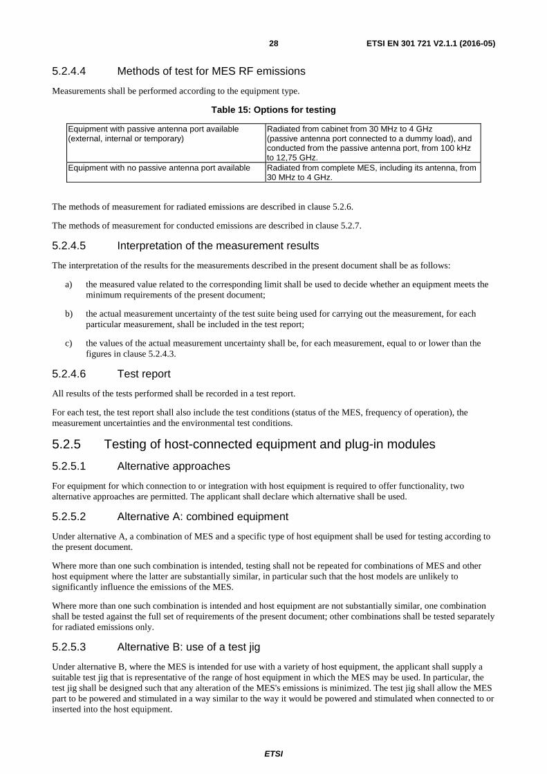
ETSI
ETSI EN 301 721 V2.1.1 (2016-05) 28
5.2.4.4 Methods of test for MES RF emissions
Measurements shall be performed according to the equipment type.
Table 15: Options for testing
Equipment with passive antenna port available (external, internal or temporary)
Radiated from cabinet from 30 MHz to 4 GHz (passive antenna port connected to a dummy load), and conducted from the passive antenna port, from 100 kHz to 12,75 GHz.
Equipment with no passive antenna port available Radiated from complete MES, including its antenna, from 30 MHz to 4 GHz.
The methods of measurement for radiated emissions are described in clause 5.2.6.
The methods of measurement for conducted emissions are described in clause 5.2.7.
5.2.4.5 Interpretation of the measurement results
The interpretation of the results for the measurements described in the present document shall be as follows:
a) the measured value related to the corresponding limit shall be used to decide whether an equipment meets the minimum requirements of the present document;
b) the actual measurement uncertainty of the test suite being used for carrying out the measurement, for each particular measurement, shall be included in the test report;
c) the values of the actual measurement uncertainty shall be, for each measurement, equal to or lower than the figures in clause 5.2.4.3.
5.2.4.6 Test report
All results of the tests performed shall be recorded in a test report.
For each test, the test report shall also include the test conditions (status of the MES, frequency of operation), the measurement uncertainties and the environmental test conditions.
5.2.5 Testing of host-connected equipment and plug-in modules
5.2.5.1 Alternative approaches
For equipment for which connection to or integration with host equipment is required to offer functionality, two alternative approaches are permitted. The applicant shall declare which alternative shall be used.
5.2.5.2 Alternative A: combined equipment
Under alternative A, a combination of MES and a specific type of host equipment shall be used for testing according to the present document.
Where more than one such combination is intended, testing shall not be repeated for combinations of MES and other host equipment where the latter are substantially similar, in particular such that the host models are unlikely to significantly influence the emissions of the MES.
Where more than one such combination is intended and host equipment are not substantially similar, one combination shall be tested against the full set of requirements of the present document; other combinations shall be tested separately for radiated emissions only.
5.2.5.3 Alternative B: use of a test jig
Under alternative B, where the MES is intended for use with a variety of host equipment, the applicant shall supply a suitable test jig that is representative of the range of host equipment in which the MES may be used. In particular, the test jig shall be designed such that any alteration of the MES's emissions is minimized. The test jig shall allow the MES part to be powered and stimulated in a way similar to the way it would be powered and stimulated when connected to or inserted into the host equipment.
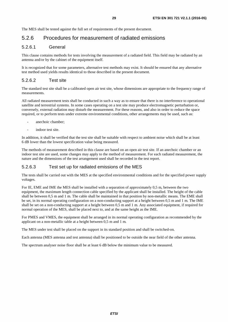
ETSI
ETSI EN 301 721 V2.1.1 (2016-05) 29
The MES shall be tested against the full set of requirements of the present document.
5.2.6 Procedures for measurement of radiated emissions
5.2.6.1 General
This clause contains methods for tests involving the measurement of a radiated field. This field may be radiated by an antenna and/or by the cabinet of the equipment itself.
It is recognized that for some parameters, alternative test methods may exist. It should be ensured that any alternative test method used yields results identical to those described in the present document.
5.2.6.2 Test site
The standard test site shall be a calibrated open air test site, whose dimensions are appropriate to the frequency range of measurements.
All radiated measurement tests shall be conducted in such a way as to ensure that there is no interference to operational satellite and terrestrial systems. In some cases operating on a test site may produce electromagnetic perturbation or, conversely, external radiation may disturb the measurement. For these reasons, and also in order to reduce the space required, or to perform tests under extreme environmental conditions, other arrangements may be used, such as:
- anechoic chamber;
- indoor test site.
In addition, it shall be verified that the test site shall be suitable with respect to ambient noise which shall be at least 6 dB lower than the lowest specification value being measured.
The methods of measurement described in this clause are based on an open air test site. If an anechoic chamber or an indoor test site are used, some changes may apply to the method of measurement. For each radiated measurement, the nature and the dimensions of the test arrangement used shall be recorded in the test report.
5.2.6.3 Test set up for radiated emissions of the MES
The tests shall be carried out with the MES at the specified environmental conditions and for the specified power supply voltages.
For IE, EME and IME the MES shall be installed with a separation of approximately 0,5 m, between the two equipment, the maximum length connection cable specified by the applicant shall be installed. The height of the cable shall be between 0,5 m and 1 m. The cable shall be maintained in that position by non-metallic means. The EME shall be set, in its normal operating configuration on a non-conducting support at a height between 0,5 m and 1 m. The IME shall be set on a non-conducting support at a height between 0,5 m and 1 m. Any associated equipment, if required for normal operation of the MES, shall be placed next to, and at the same height as the IME.
For PMES and VMES, the equipment shall be arranged in its normal operating configuration as recommended by the applicant on a non-metallic table at a height between 0,5 m and 1 m.
The MES under test shall be placed on the support in its standard position and shall be switched-on.
Each antenna (MES antenna and test antenna) shall be positioned to be outside the near field of the other antenna.
The spectrum analyser noise floor shall be at least 6 dB below the minimum value to be measured.
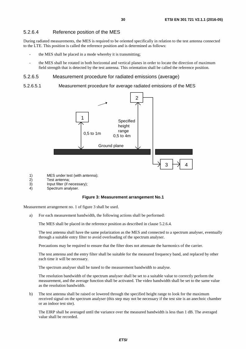
ETSI
ETSI EN 301 721 V2.1.1 (2016-05) 30
5.2.6.4 Reference position of the MES
During radiated measurements, the MES is required to be oriented specifically in relation to the test antenna connected to the LTE. This position is called the reference position and is determined as follows:
- the MES shall be placed in a mode whereby it is transmitting;
- the MES shall be rotated in both horizontal and vertical planes in order to locate the direction of maximum field strength that is detected by the test antenna. This orientation shall be called the reference position.
5.2.6.5 Measurement procedure for radiated emissions (average)
5.2.6.5.1 Measurement procedure for average radiated emissions of the MES
1) MES under test (with antenna); 2) Test antenna; 3) Input filter (if necessary); 4) Spectrum analyser.
Figure 3: Measurement arrangement No.1
Measurement arrangement no. 1 of figure 3 shall be used.
a) For each measurement bandwidth, the following actions shall be performed:
The MES shall be placed in the reference position as described in clause 5.2.6.4.
The test antenna shall have the same polarization as the MES and connected to a spectrum analyser, eventually through a suitable entry filter to avoid overloading of the spectrum analyser.
Precautions may be required to ensure that the filter does not attenuate the harmonics of the carrier.
The test antenna and the entry filter shall be suitable for the measured frequency band, and replaced by other each time it will be necessary.
The spectrum analyser shall be tuned to the measurement bandwidth to analyse.
The resolution bandwidth of the spectrum analyser shall be set to a suitable value to correctly perform the measurement, and the average function shall be activated. The video bandwidth shall be set to the same value as the resolution bandwidth.
b) The test antenna shall be raised or lowered through the specified height range to look for the maximum received signal on the spectrum analyser (this step may not be necessary if the test site is an anechoic chamber or an indoor test site).
The EIRP shall be averaged until the variance over the measured bandwidth is less than 1 dB. The averaged value shall be recorded.
1
2
3
Ground plane
0,5 to 1m
Specifiedheightrange
0,5 to 4m
4
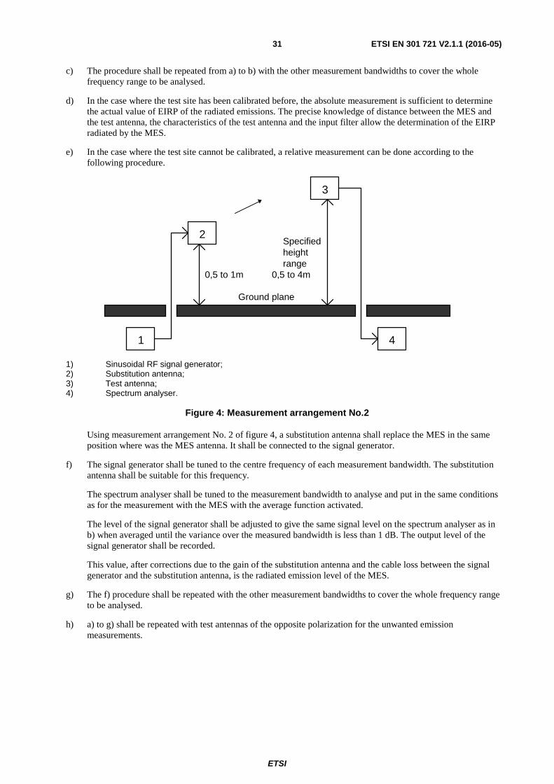
ETSI
ETSI EN 301 721 V2.1.1 (2016-05) 31
c) The procedure shall be repeated from a) to b) with the other measurement bandwidths to cover the whole frequency range to be analysed.
d) In the case where the test site has been calibrated before, the absolute measurement is sufficient to determine the actual value of EIRP of the radiated emissions. The precise knowledge of distance between the MES and the test antenna, the characteristics of the test antenna and the input filter allow the determination of the EIRP radiated by the MES.
e) In the case where the test site cannot be calibrated, a relative measurement can be done according to the following procedure.
1) Sinusoidal RF signal generator; 2) Substitution antenna; 3) Test antenna; 4) Spectrum analyser.
Figure 4: Measurement arrangement No.2
Using measurement arrangement No. 2 of figure 4, a substitution antenna shall replace the MES in the same position where was the MES antenna. It shall be connected to the signal generator.
f) The signal generator shall be tuned to the centre frequency of each measurement bandwidth. The substitution antenna shall be suitable for this frequency.
The spectrum analyser shall be tuned to the measurement bandwidth to analyse and put in the same conditions as for the measurement with the MES with the average function activated.
The level of the signal generator shall be adjusted to give the same signal level on the spectrum analyser as in b) when averaged until the variance over the measured bandwidth is less than 1 dB. The output level of the signal generator shall be recorded.
This value, after corrections due to the gain of the substitution antenna and the cable loss between the signal generator and the substitution antenna, is the radiated emission level of the MES.
g) The f) procedure shall be repeated with the other measurement bandwidths to cover the whole frequency range to be analysed.
h) a) to g) shall be repeated with test antennas of the opposite polarization for the unwanted emission measurements.
2
3
4
Ground plane
Specifiedheightrange
0,5 to 4m
1
0,5 to 1m
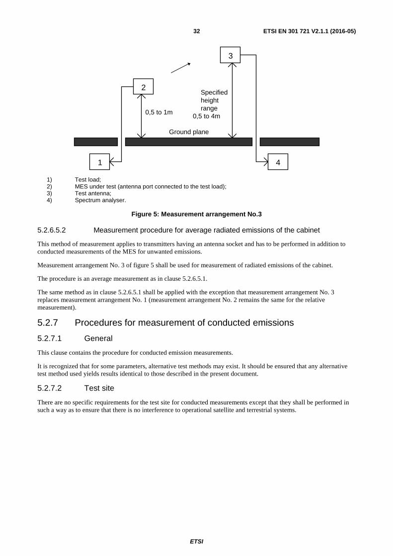
ETSI
ETSI EN 301 721 V2.1.1 (2016-05) 32
1) Test load; 2) MES under test (antenna port connected to the test load); 3) Test antenna; 4) Spectrum analyser.
Figure 5: Measurement arrangement No.3
5.2.6.5.2 Measurement procedure for average radiated emissions of the cabinet
This method of measurement applies to transmitters having an antenna socket and has to be performed in addition to conducted measurements of the MES for unwanted emissions.
Measurement arrangement No. 3 of figure 5 shall be used for measurement of radiated emissions of the cabinet.
The procedure is an average measurement as in clause 5.2.6.5.1.
The same method as in clause 5.2.6.5.1 shall be applied with the exception that measurement arrangement No. 3 replaces measurement arrangement No. 1 (measurement arrangement No. 2 remains the same for the relative measurement).
5.2.7 Procedures for measurement of conducted emissions
5.2.7.1 General
This clause contains the procedure for conducted emission measurements.
It is recognized that for some parameters, alternative test methods may exist. It should be ensured that any alternative test method used yields results identical to those described in the present document.
5.2.7.2 Test site
There are no specific requirements for the test site for conducted measurements except that they shall be performed in such a way as to ensure that there is no interference to operational satellite and terrestrial systems.
2
3
4
Ground plane
0,5 to 1m
Specifiedheightrange
0,5 to 4m
1
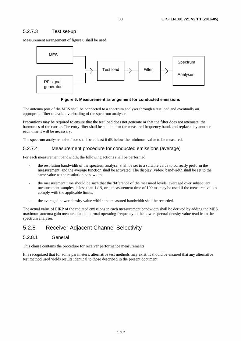
ETSI
ETSI EN 301 721 V2.1.1 (2016-05) 33
5.2.7.3 Test set-up
Measurement arrangement of figure 6 shall be used.
generator
Test load Filter
Spectrum
Analyser
RF signal
MES
Figure 6: Measurement arrangement for conducted emissions
The antenna port of the MES shall be connected to a spectrum analyser through a test load and eventually an appropriate filter to avoid overloading of the spectrum analyser.
Precautions may be required to ensure that the test load does not generate or that the filter does not attenuate, the harmonics of the carrier. The entry filter shall be suitable for the measured frequency band, and replaced by another each time it will be necessary.
The spectrum analyser noise floor shall be at least 6 dB below the minimum value to be measured.
5.2.7.4 Measurement procedure for conducted emissions (average)
For each measurement bandwidth, the following actions shall be performed:
- the resolution bandwidth of the spectrum analyser shall be set to a suitable value to correctly perform the measurement, and the average function shall be activated. The display (video) bandwidth shall be set to the same value as the resolution bandwidth;
- the measurement time should be such that the difference of the measured levels, averaged over subsequent measurement samples, is less than 1 dB, or a measurement time of 100 ms may be used if the measured values comply with the applicable limits;
- the averaged power density value within the measured bandwidth shall be recorded.
The actual value of EIRP of the radiated emissions in each measurement bandwidth shall be derived by adding the MES maximum antenna gain measured at the normal operating frequency to the power spectral density value read from the spectrum analyser.
5.2.8 Receiver Adjacent Channel Selectivity
5.2.8.1 General
This clause contains the procedure for receiver performance measurements.
It is recognized that for some parameters, alternative test methods may exist. It should be ensured that any alternative test method used yields results identical to those described in the present document.
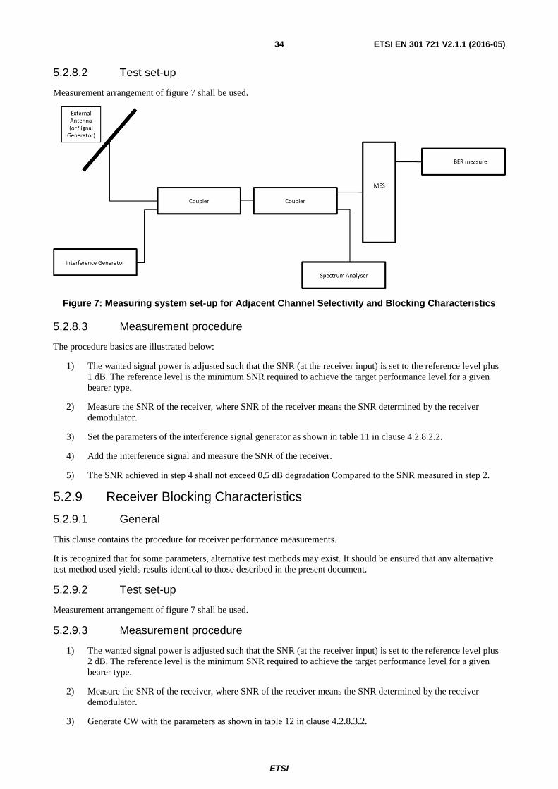
ETSI
ETSI EN 301 721 V2.1.1 (2016-05) 34
5.2.8.2 Test set-up
Measurement arrangement of figure 7 shall be used.
Figure 7: Measuring system set-up for Adjacent Channel Selectivity and Blocking Characteristics
5.2.8.3 Measurement procedure
The procedure basics are illustrated below:
1) The wanted signal power is adjusted such that the SNR (at the receiver input) is set to the reference level plus 1 dB. The reference level is the minimum SNR required to achieve the target performance level for a given bearer type.
2) Measure the SNR of the receiver, where SNR of the receiver means the SNR determined by the receiver demodulator.
3) Set the parameters of the interference signal generator as shown in table 11 in clause 4.2.8.2.2.
4) Add the interference signal and measure the SNR of the receiver.
5) The SNR achieved in step 4 shall not exceed 0,5 dB degradation Compared to the SNR measured in step 2.
5.2.9 Receiver Blocking Characteristics
5.2.9.1 General
This clause contains the procedure for receiver performance measurements.
It is recognized that for some parameters, alternative test methods may exist. It should be ensured that any alternative test method used yields results identical to those described in the present document.
5.2.9.2 Test set-up
Measurement arrangement of figure 7 shall be used.
5.2.9.3 Measurement procedure
1) The wanted signal power is adjusted such that the SNR (at the receiver input) is set to the reference level plus 2 dB. The reference level is the minimum SNR required to achieve the target performance level for a given bearer type.
2) Measure the SNR of the receiver, where SNR of the receiver means the SNR determined by the receiver demodulator.
3) Generate CW with the parameters as shown in table 12 in clause 4.2.8.3.2.
ETSI
ETSI EN 301 721 V2.1.1 (2016-05) 35
4) Apply the interference CW and measure the receiver SNR.
5) The SNR achieved in step 4 shall not exceed 1 dB degradation compared to the SNR measured in step 2.

ETSI
ETSI EN 301 721 V2.1.1 (2016-05) 36
Annex A (normative): Relationship between the present document and the essential requirements of Directive 2014/53/EU The present document has been prepared under the Commission's standardisation request C(2015) 5376 final [i.2] to provide one voluntary means of conforming to the essential requirements of Directive 2014/53/EU on the harmonisation of the laws of the Member States relating to the making available on the market of radio equipment and repealing Directive 1999/5/EC [7].
Once the present document is cited in the Official Journal of the European Union under that Directive, compliance with the normative clauses of the present document given in table A.1 confers, within the limits of the scope of the present document, a presumption of conformity with the corresponding essential requirements of that Directive, and associated EFTA regulations.
Recital 10 of Directive 2014/53/EU [7] states that: "In order to ensure that radio equipment uses the radio spectrum effectively and supports the efficient use of radio spectrum, radio equipment should be constructed so that: in the case of a transmitter, when the transmitter is properly installed, maintained and used for its intended purpose it generates radio waves emissions that do not create harmful interference, while unwanted radio waves emissions generated by the transmitter (e.g. in adjacent channels) with a potential negative impact on the goals of radio spectrum policy should be limited to such a level that, according to the state of the art, harmful interference is avoided; and, in the case of a receiver, it has a level of performance that allows it to operate as intended and protects it against the risk of harmful interference, in particular from shared or adjacent channels, and, in so doing, supports improvements in the efficient use of shared or adjacent channels."
Recital 11 of Directive 2014/53/EU [7] states that: "Although receivers do not themselves cause harmful interference, reception capabilities are an increasingly important factor in ensuring the efficient use of radio spectrum by way of an increased resilience of receivers against harmful interference and unwanted signals on the basis of the relevant essential requirements of Union harmonisation legislation."
As a consequence, the present document includes both transmitting and receiving parameters to maximize the efficient use of radio spectrum.
Table A.1: Relationship between the present document and the essential requirements of Directive 2014/53/EU
Harmonised Standard ETSI EN 301 721 The following requirements are relevant to the presumption of conformity
under the article 3.2 of Directive 2014/53/EU [7] Requirement Requirement Conditionality
No Description Reference: Clause No U/C Condition
1 Unwanted emission outside the bands 148 MHz to 150,05 MHz, 235 MHz to 322 MHz, 335,4 MHz to 399,9 MHz and 399,9 MHz to 400,05 MHz (carrier-on state)
4.2.1 U
2 Unwanted emission within the bands 148 MHz to 150,05 MHz, 235 MHz to 322 MHz, 335,4 MHz to 399,9 MHz and 399,9 MHz to 400,05 MHz (carrier-on state)
4.2.2 U
3 EIRP density within the operational band 4.2.3 U 4 Unwanted emissions in carrier-off state 4.2.4 U 5 Processor monitoring 4.2.5.3.1 U 6 Transmit frequency generation subsystem
monitoring 4.2.5.3.1.2 U
7 Network control authorization 4.2.5.3.2 U 8 Transmission disable/enable 4.2.5.3.3.1 U 9 Transmit frequency control 4.2.5.3.4 U 10 Equipment identity 4.2.6 U 11 Protection of the Radio Astronomy Service
(RAS) from emissions produced by the MES in the bands 150,05 MHz to 153 MHz, 322 MHz to 328,6 MHz and 406,1 MHz to 410 MHz
4.2.7 U
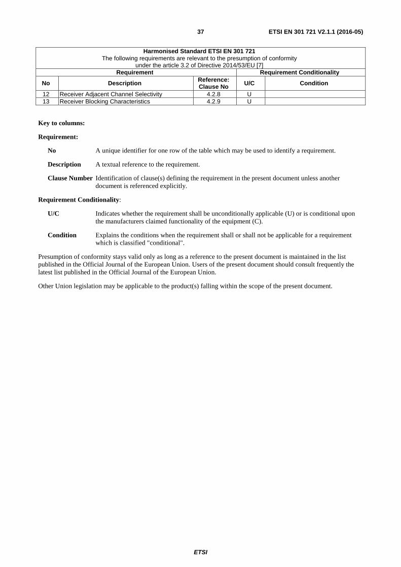
ETSI
ETSI EN 301 721 V2.1.1 (2016-05) 37
Harmonised Standard ETSI EN 301 721 The following requirements are relevant to the presumption of conformity
under the article 3.2 of Directive 2014/53/EU [7] Requirement Requirement Conditionality
No Description Reference: Clause No U/C Condition
12 Receiver Adjacent Channel Selectivity 4.2.8 U 13 Receiver Blocking Characteristics 4.2.9 U
Key to columns:
Requirement:
No A unique identifier for one row of the table which may be used to identify a requirement.
Description A textual reference to the requirement.
Clause Number Identification of clause(s) defining the requirement in the present document unless another document is referenced explicitly.
Requirement Conditionality:
U/C Indicates whether the requirement shall be unconditionally applicable (U) or is conditional upon the manufacturers claimed functionality of the equipment (C).
Condition Explains the conditions when the requirement shall or shall not be applicable for a requirement which is classified "conditional".
Presumption of conformity stays valid only as long as a reference to the present document is maintained in the list published in the Official Journal of the European Union. Users of the present document should consult frequently the latest list published in the Official Journal of the European Union.
Other Union legislation may be applicable to the product(s) falling within the scope of the present document.
ETSI
ETSI EN 301 721 V2.1.1 (2016-05) 38
Annex B (informative): Bibliography
• Directive 98/13/EC of the European Parliament and of the Council of 12 February 1998 relating to telecommunications terminal equipment and satellite earth station equipment, including the mutual recognition of their conformity.
• ETSI ETS 300 721: "Satellite Earth Stations and Systems (SES); Mobile Earth Stations (MES) providing Low Bit Rate Data Communications (LBRDC) using LEO satellites operating below 1 GHz".
• ETSI EN 301 489-20: "Electromagnetic compatibility and Radio spectrum Matters (ERM); ElectroMagnetic Compatibility (EMC) standard for radio equipment and services; Part 20: Specific conditions for Mobile Earth Stations (MES) used in the Mobile Satellite Services (MSS)".
• Council Directive 73/23/EEC of 19 February 1973 on the harmonization of the laws of Member States relating to electrical equipment designed for use within certain voltage limits (Low Voltage Directive).
• Council Directive 92/31/EEC of 28 April 1992 amending Directive 89/336/EEC on the approximation of the laws of the Member States relating to electromagnetic compatibility (EMC Directive).
• CENELEC EN 5502: "Limits and methods of measurement of radio disturbance characteristics of information technology equipment".
• Directive 1999/5/EC of the European Parliament and of the Council of 9 March 1999 on radio equipment and telecommunications terminal equipment and the mutual recognition of their conformity.
• Directive 98/34/EC of the European Parliament and of the Council of 22 June 1998 laying down a procedure for the provision of information in the field of technical standards and regulations.
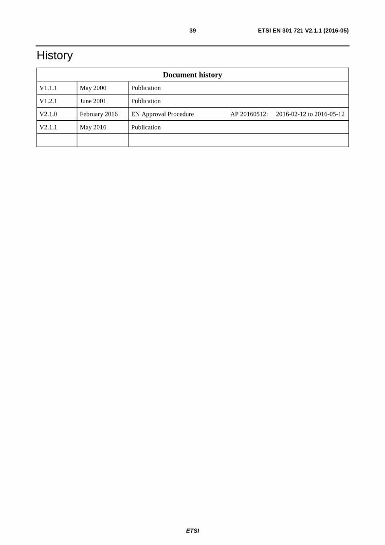
ETSI
ETSI EN 301 721 V2.1.1 (2016-05) 39
History
Document history
V1.1.1 May 2000 Publication
V1.2.1 June 2001 Publication
V2.1.0 February 2016 EN Approval Procedure AP 20160512: 2016-02-12 to 2016-05-12
V2.1.1 May 2016 Publication