en 302 217-2 - v3.0.8 - fixed radio systems; characteristics and
TRANSCRIPT

Draft ETSI EN 302 217-2 V3.0.8 (2016-06)
Fixed Radio Systems; Characteristics and requirements for
point-to-point equipment and antennas; Part 2: Digital systems operating in frequency bands
from 1,3 GHz to 86 GHz; Harmonised Standard covering the essential requirements
of article 3.2 of Directive 2014/53/EU
HARMONISED EUROPEAN STANDARD

ETSI
Draft ETSI EN 302 217-2 V3.0.8 (2016-06)2
Reference REN/ATTM-0431
Keywords antenna, DFRS, digital, DRRS, FWA,
point-to-point, radio, regulation, transmission
ETSI
650 Route des Lucioles F-06921 Sophia Antipolis Cedex - FRANCE
Tel.: +33 4 92 94 42 00 Fax: +33 4 93 65 47 16
Siret N° 348 623 562 00017 - NAF 742 C
Association à but non lucratif enregistrée à la Sous-Préfecture de Grasse (06) N° 7803/88
Important notice
The present document can be downloaded from: http://www.etsi.org/standards-search
The present document may be made available in electronic versions and/or in print. The content of any electronic and/or print versions of the present document shall not be modified without the prior written authorization of ETSI. In case of any
existing or perceived difference in contents between such versions and/or in print, the only prevailing document is the print of the Portable Document Format (PDF) version kept on a specific network drive within ETSI Secretariat.
Users of the present document should be aware that the document may be subject to revision or change of status. Information on the current status of this and other ETSI documents is available at
https://portal.etsi.org/TB/ETSIDeliverableStatus.aspx
If you find errors in the present document, please send your comment to one of the following services: https://portal.etsi.org/People/CommiteeSupportStaff.aspx
Copyright Notification
No part may be reproduced or utilized in any form or by any means, electronic or mechanical, including photocopying and microfilm except as authorized by written permission of ETSI.
The content of the PDF version shall not be modified without the written authorization of ETSI. The copyright and the foregoing restriction extend to reproduction in all media.
© European Telecommunications Standards Institute 2016.
All rights reserved.
DECTTM, PLUGTESTSTM, UMTSTM and the ETSI logo are Trade Marks of ETSI registered for the benefit of its Members. 3GPPTM and LTE™ are Trade Marks of ETSI registered for the benefit of its Members and
of the 3GPP Organizational Partners. GSM® and the GSM logo are Trade Marks registered and owned by the GSM Association.

ETSI
Draft ETSI EN 302 217-2 V3.0.8 (2016-06)3
Contents
Intellectual Property Rights ................................................................................................................................ 9
Foreword ............................................................................................................................................................. 9
Modal verbs terminology .................................................................................................................................... 9
Introduction ........................................................................................................................................................ 9
1 Scope ...................................................................................................................................................... 10
1.1 Generality ......................................................................................................................................................... 10
1.1.1 Applicability ............................................................................................................................................... 10
1.1.2 Operating frequency bands ......................................................................................................................... 10
1.2 Spectral efficiency classes ................................................................................................................................ 10
1.3 System alternatives ........................................................................................................................................... 11
1.4 Channel arrangements and utilization .............................................................................................................. 12
1.5 Payload flexibility ............................................................................................................................................ 12
1.6 Specific Requirements for frequency bands ..................................................................................................... 12
2 References .............................................................................................................................................. 13
2.1 Normative references ....................................................................................................................................... 13
2.2 Informative references ...................................................................................................................................... 14
3 Definitions, symbols and abbreviations ................................................................................................. 17
3.1 Definitions ........................................................................................................................................................ 17
3.2 Symbols ............................................................................................................................................................ 17
3.3 Abbreviations ................................................................................................................................................... 17
4 Technical requirements specifications ................................................................................................... 18
4.1 General requirements ....................................................................................................................................... 18
4.1.1 Requirements framework ............................................................................................................................ 18
4.1.2 Minimum RIC density ................................................................................................................................ 19
4.1.3 Payload flexibility ....................................................................................................................................... 20
4.1.4 System identification and traffic loading .................................................................................................... 20
4.1.5 Environmental profile ................................................................................................................................. 21
4.2 Transmitter requirements ................................................................................................................................. 22
4.2.0 General: system loading .............................................................................................................................. 22
4.2.1 Transmitter power and power tolerance ...................................................................................................... 22
4.2.1.1 Maximum power and EIRP ................................................................................................................... 22
4.2.1.2 Combined TX power output and EIRP limits ....................................................................................... 22
4.2.1.3 Output power tolerance ......................................................................................................................... 23
4.2.2 Transmitter power and frequency control ................................................................................................... 23
4.2.2.1 Power Control (ATPC and RTPC) ........................................................................................................ 23
4.2.2.1.0 General background ......................................................................................................................... 23
4.2.2.1.1 Automatic Transmit Power Control (ATPC) ................................................................................... 23
4.2.2.1.2 Remote Transmit Power Control (RTPC) ....................................................................................... 24
4.2.2.2 Remote Frequency Control (RFC) ........................................................................................................ 24
4.2.3 Radio Frequency (RF) spectrum mask........................................................................................................ 24
4.2.3.1 Limits background ................................................................................................................................ 24
4.2.3.2 Limits .................................................................................................................................................... 27
4.2.4 Discrete CW components exceeding the spectrum mask limit ................................................................... 40
4.2.4.1 Discrete CW components at the symbol rate ........................................................................................ 40
4.2.4.2 Other discrete CW components exceeding the spectrum mask limit .................................................... 40
4.2.5 Unwanted emissions in the spurious domain - external .............................................................................. 41
4.2.6 Dynamic Change of Modulation Order ...................................................................................................... 42
4.2.7 Radio frequency tolerance .......................................................................................................................... 42
4.2.8 Emission limitations outside the allocated band ......................................................................................... 43
4.3 Receiver requirements ...................................................................................................................................... 43
4.3.0 General: System loading ............................................................................................................................. 43
4.3.1 Unwanted emissions in the spurious domain - external .............................................................................. 43
4.3.2 BER as a function of receiver input signal level RSL ................................................................................ 43
4.3.3 Receiver selectivity ..................................................................................................................................... 44

ETSI
Draft ETSI EN 302 217-2 V3.0.8 (2016-06)4
4.3.3.1 Introduction ........................................................................................................................................... 44
4.3.3.2 Co-channel "external", first and second adjacent channel interference sensitivity ............................... 45
4.3.3.2.1 Requirements basics ........................................................................................................................ 45
4.3.3.2.2 Limits for co-channel and first adjacent channel ............................................................................. 45
4.3.3.2.3 Limits for second adjacent channel interference ............................................................................. 46
4.3.3.3 CW spurious interference (blocking & spurious response rejection) .................................................... 46
4.4 Antenna Characteristics .................................................................................................................................... 47
4.4.1 Integral antennas or dedicated antennas...................................................................................................... 47
4.4.1.1 Introduction ........................................................................................................................................... 47
4.4.1.2 Radiation Pattern Envelope (Off-axis EIRP density) ............................................................................ 47
4.4.1.3 Antenna gain ......................................................................................................................................... 47
4.4.1.4 Antenna Cross-Polar Discrimination (XPD) ......................................................................................... 48
4.4.2 Guidelines for stand-alone antennas ........................................................................................................... 48
5 Testing for compliance with technical requirements .............................................................................. 48
5.1 Environmental and other conditions for testing ................................................................................................ 48
5.1.1 Environmental conditions ........................................................................................................................... 48
5.1.2 Test interpretation and measurement uncertainty ....................................................................................... 49
5.1.3 Other basic conditions ................................................................................................................................ 49
5.2 Test methods for the transmitter ....................................................................................................................... 50
5.2.0 General test summary ................................................................................................................................. 50
5.2.1 Transmitter power and power tolerance ...................................................................................................... 51
5.2.1.1 Transmitter power and EIRP ................................................................................................................. 51
5.2.1.2 Combined TX power output and EIRP limits ....................................................................................... 51
5.2.1.3 Output power tolerance ......................................................................................................................... 52
5.2.2 Transmitter power and frequency control ................................................................................................... 52
5.2.2.1 Transmitter Power Control (ATPC and RTPC) .................................................................................... 52
5.2.2.1.1 ATPC ............................................................................................................................................... 52
5.2.2.1.2 RTPC ............................................................................................................................................... 52
5.2.2.2 Remote Frequency Control (RFC) ........................................................................................................ 52
5.2.3 RF spectrum mask ...................................................................................................................................... 52
5.2.4 Discrete CW components exceeding the spectrum mask limit ................................................................... 53
5.2.5 Unwanted emissions in the spurious domain - external .............................................................................. 53
5.2.6 Dynamic Change of Modulation Order ...................................................................................................... 53
5.2.7 Radio frequency tolerance .......................................................................................................................... 54
5.3 Test methods for the receiver ........................................................................................................................... 54
5.3.0 General test summary ................................................................................................................................. 54
5.3.1 Unwanted emissions in the spurious domain - external .............................................................................. 55
5.3.2 BER as a function of receiver input signal level (RSL) .............................................................................. 55
5.3.3 Receiver selectivity ..................................................................................................................................... 56
5.3.3.1 Void....................................................................................................................................................... 56
5.3.3.2 Co-channel "external", first and second adjacent channel interference sensitivity ............................... 56
5.3.3.2.1 Co-channel and first adjacent channel ............................................................................................. 56
5.3.3.2.2 Second adjacent channel .................................................................................................................. 56
5.3.3.3 CW spurious interference ...................................................................................................................... 56
5.4 Additional antenna test methods for systems with integral or dedicated antenna ............................................ 56
5.4.0 General test summary ................................................................................................................................. 56
5.4.1 Radiation Pattern Envelope (Off-axis EIRP density) .................................................................................. 57
5.4.2 Antenna gain ............................................................................................................................................... 57
5.4.3 Antenna Cross-Polar Discrimination (XPD) ............................................................................................... 57
Annex A (normative): Relationship between the present document and the essential requirements of Directive 2014/53/EU ......................................................... 58
Annex B (normative): Frequency bands from 1,4 GHz to 2,6 GHz ................................................ 60
B.1 Introduction ............................................................................................................................................ 60
B.2 General characteristics ........................................................................................................................... 60
B.2.1 Frequency characteristics and channel arrangements ....................................................................................... 60
B.2.2 Transmission capacities .................................................................................................................................... 60
B.3 Transmitter ............................................................................................................................................. 61

ETSI
Draft ETSI EN 302 217-2 V3.0.8 (2016-06)5
B.3.1 General requirements ....................................................................................................................................... 61
B.3.2 RF spectrum masks options .............................................................................................................................. 61
B.4 Receiver .................................................................................................................................................. 62
B.4.1 General requirements ....................................................................................................................................... 62
B.4.2 BER as a function of receiver input signal level (RSL) ................................................................................... 62
B.4.3 Co-channel "external" and adjacent channels interference sensitivity ............................................................. 63
Annex C (normative): Frequency bands from 3 GHz to 11 GHz (channel separation up to 30 MHz and 56/60 MHz) ............................................................................... 65
C.1 Introduction ............................................................................................................................................ 65
C.2 General characteristics ........................................................................................................................... 65
C.2.1 Frequency characteristics and channel arrangements ....................................................................................... 65
C.2.2 Transmission capacities .................................................................................................................................... 66
C.3 Transmitter ............................................................................................................................................. 67
C.3.1 General requirements ....................................................................................................................................... 67
C.3.2 RF spectrum masks .......................................................................................................................................... 67
C.4 Receiver .................................................................................................................................................. 67
C.4.1 General requirements ....................................................................................................................................... 67
C.4.2 BER as a function of Receiver input Signal Level (RSL) ................................................................................ 67
C.4.3 Co-channel "external" and adjacent channel interference sensitivity ............................................................... 69
Annex D (normative): Frequency bands from 3 GHz to 11 GHz (channel separation 40 MHz) .......................................................................................................... 70
D.1 Introduction ............................................................................................................................................ 70
D.2 General characteristics ........................................................................................................................... 70
D.2.1 Frequency characteristics and channel arrangements ....................................................................................... 70
D.2.2 Transmission capacities .................................................................................................................................... 70
D.3 Transmitter ............................................................................................................................................. 71
D.3.1 General requirements ....................................................................................................................................... 71
D.3.2 RF spectrum masks .......................................................................................................................................... 71
D.4 Receiver .................................................................................................................................................. 72
D.4.1 General requirements ....................................................................................................................................... 72
D.4.2 BER as a function of Receiver input Signal Level (RSL) ................................................................................ 72
D.4.3 Co-channel "external" and adjacent channel interference sensitivity ............................................................... 73
Annex E (normative): Frequency bands 13 GHz, 15 GHz and 18 GHz .......................................... 74
E.1 Introduction ............................................................................................................................................ 74
E.2 General characteristics ........................................................................................................................... 74
E.2.1 Frequency characteristics and channel arrangements ....................................................................................... 74
E.2.2 Transmission capacities .................................................................................................................................... 75
E.3 Transmitter ............................................................................................................................................. 75
E.3.1 General requirements ....................................................................................................................................... 75
E.3.2 RF spectrum masks .......................................................................................................................................... 75
E.4 Receiver .................................................................................................................................................. 76
E.4.1 General requirements ....................................................................................................................................... 76
E.4.2 BER as a function of Receiver input Signal Level (RSL) ................................................................................ 76
E.4.3 Co-channel "external" and adjacent channel interference sensitivity ............................................................... 78
Annex F (normative): Frequency bands from 23 GHz to 42 GHz .................................................. 80
F.1 Introduction ............................................................................................................................................ 80
F.2 General characteristics ........................................................................................................................... 80
F.2.1 Frequency characteristics and channel arrangements ....................................................................................... 80
F.2.2 Transmission capacities .................................................................................................................................... 81

ETSI
Draft ETSI EN 302 217-2 V3.0.8 (2016-06)6
F.3 Transmitter ............................................................................................................................................. 81
F.3.1 General requirements ....................................................................................................................................... 81
F.3.2 RF spectrum masks .......................................................................................................................................... 81
F.4 Receiver .................................................................................................................................................. 82
F.4.1 General requirements ....................................................................................................................................... 82
F.4.2 BER as a function of Receiver input Signal Level (RSL) ................................................................................ 82
F.4.3 Co-channel "external" and adjacent channel interference sensitivity ............................................................... 85
Annex G (normative): Frequency bands from 50 GHz to 55 GHz .................................................. 86
G.1 Introduction ............................................................................................................................................ 86
G.2 General characteristics ........................................................................................................................... 86
G.2.1 Frequency characteristics and channel arrangements ....................................................................................... 86
G.2.2 Transmission capacities .................................................................................................................................... 87
G.3 Transmitter ............................................................................................................................................. 87
G.3.1 General requirements ....................................................................................................................................... 87
G.3.2 RF spectrum masks .......................................................................................................................................... 87
G.4 Receiver .................................................................................................................................................. 87
G.4.1 General requirements ....................................................................................................................................... 87
G.4.2 BER as a function of Receiver input Signal Level (RSL) ................................................................................ 88
G.4.3 Co-channel "external" and adjacent channel interference sensitivity ............................................................... 88
Annex H (normative): Frequency band 57 GHz to 66 GHz ............................................................. 89
H.1 Introduction ............................................................................................................................................ 89
H.2 General characteristics ........................................................................................................................... 89
H.2.1 Frequency characteristics and channel arrangements ....................................................................................... 89
H.2.2 Transmission capacities .................................................................................................................................... 89
H.3 Transmitter ............................................................................................................................................. 90
H.3.1 General requirements ....................................................................................................................................... 90
H.3.2 Combined TX power output and EIRP limits................................................................................................... 90
H.3.2.1 Maximum power and EIRP ........................................................................................................................ 90
H.3.2.2 Equipment without ATPC as permanent feature ........................................................................................ 91
H.3.2.3 Equipment implementing ATPC as permanent feature............................................................................... 91
H.3.3 RF spectrum masks .......................................................................................................................................... 93
H.3.4 Emissions outside the 57 GHz to 66 GHz range .............................................................................................. 94
H.4 Receiver .................................................................................................................................................. 94
H.4.1 General requirements ....................................................................................................................................... 94
H.4.2 BER as a function of Receiver input Signal Level (RSL) ................................................................................ 94
H.4.3 Co-channel "external" and adjacent channel interference sensitivity ............................................................... 95
H.5 Minimum antenna gain ........................................................................................................................... 96
Annex I (normative): Frequency band 64 GHz to 66 GHz ............................................................. 97
I.1 Introduction ............................................................................................................................................ 97
I.2 General characteristics ........................................................................................................................... 97
I.2.1 Frequency characteristics and channel arrangements ....................................................................................... 97
I.2.2 Transmission capacities .................................................................................................................................... 98
I.2.2.1 Channel arrangement based on N × 50 MHz .............................................................................................. 98
I.2.2.2 Channel arrangement based on N × 30 MHz .............................................................................................. 98
I.3 Transmitter ............................................................................................................................................. 99
I.3.1 General requirements ....................................................................................................................................... 99
I.3.2 Combined TX power and EIRP limits .............................................................................................................. 99
I.3.2.1 Generality ................................................................................................................................................... 99
I.3.2.2 Equipment without ATPC as permanent feature ........................................................................................ 99
I.3.2.3 Equipment implementing ATPC as permanent feature............................................................................. 100
I.3.3 RF spectrum mask .......................................................................................................................................... 102

ETSI
Draft ETSI EN 302 217-2 V3.0.8 (2016-06)7
I.3.4 Emissions outside the 64 GHz to 66 GHz range ............................................................................................ 102
I.4 Receiver ................................................................................................................................................ 102
I.4.1 General requirements ..................................................................................................................................... 102
I.4.2 BER as a function of Receiver input Signal Level (RSL) .............................................................................. 102
I.4.2.1 Channel arrangement based on N × 50 MHz ............................................................................................ 102
I.4.2.2 Channel arrangement based on N × 30 MHz ............................................................................................ 102
I.4.3 Co-channel "external" and adjacent channel interference sensitivity ............................................................. 103
I.4.3.1 Channel arrangement based on N × 50 MHz ............................................................................................ 103
I.4.3.2 Channel arrangement based on N × 30 MHz ............................................................................................ 104
I.5 Minimum antenna gain ......................................................................................................................... 104
Annex J (normative): Frequency bands from 71 GHz to 86 GHz ................................................ 105
J.1 Introduction .......................................................................................................................................... 105
J.2 General characteristics ......................................................................................................................... 105
J.2.1 Frequency characteristics and channel arrangements ..................................................................................... 105
J.2.2 Transmission capacities .................................................................................................................................. 106
J.3 Transmitter ........................................................................................................................................... 106
J.3.1 General requirements ..................................................................................................................................... 106
J.3.2 Combined maximum transmitter power and EIRP ......................................................................................... 107
J.3.2.1 Generality ................................................................................................................................................. 107
J.3.2.2 Equipment without ATPC as permanent feature ...................................................................................... 107
J.3.2.3 Equipment implementing ATPC as permanent feature............................................................................. 108
J.3.3 RF spectrum masks ........................................................................................................................................ 110
J.3.4 Emissions outside the 71 GHz to 76 GHz and 81 GHz to 86 GHz ranges ..................................................... 110
J.3.4.1 General requirement ................................................................................................................................. 110
J.3.4.2 Requirement for emissions above 86 GHz band edge .............................................................................. 110
J.3.4.3 Conformance statement (see note) ............................................................................................................ 111
J.4 Receiver ................................................................................................................................................ 111
J.4.1 General requirements ..................................................................................................................................... 111
J.4.2 BER as a function of Receiver input Signal Level (RSL) .............................................................................. 111
J.4.3 Co-channel "external" and adjacent channel interference sensitivity ............................................................. 113
J.5 Minimum antenna gain ......................................................................................................................... 114
Annex K: Void ...................................................................................................................................... 115
Annex L: Void ...................................................................................................................................... 116
Annex M: Void ...................................................................................................................................... 117
Annex N (normative): Definition of equivalent data rates for packet data, PDH/SDH and other signals on the traffic interface........................................................... 118
N.1 Introduction .......................................................................................................................................... 118
N.2 General characteristics ......................................................................................................................... 118
N.2.1 Frequency characteristics and channel arrangements ..................................................................................... 118
N.2.2 Transmission capacities .................................................................................................................................. 118
N.3 System parameters ................................................................................................................................ 121
N.3.0 Introduction .................................................................................................................................................... 121
N.3.1 Transmitter ..................................................................................................................................................... 121
N.3.2 Receiver .......................................................................................................................................................... 121
N.3.3 FER as a function of BER .............................................................................................................................. 121
Annex O (normative): Test report in relation to flexible systems applications ............................ 123
O.1 Wide radio-frequency band covering units .......................................................................................... 123
O.2 Multirate/multiformat equipment ......................................................................................................... 125
O.2.0 Introduction .................................................................................................................................................... 125

ETSI
Draft ETSI EN 302 217-2 V3.0.8 (2016-06)8
O.2.1 Generic required tests in the test report .......................................................................................................... 126
O.2.2 Reduced set of required tests in the test report ............................................................................................... 126
O.2.2.0 Introduction............................................................................................................................................... 126
O.2.2.1 Reduced transmitter tests .......................................................................................................................... 126
O.2.2.2 Reduced receiver tests .............................................................................................................................. 127
O.2.3 Bandwidth adaptive test set requirements ...................................................................................................... 128
O.3 BER and C/I measurement in multi-channels systems (including channels-aggregation) when common SDH or Ethernet single/multiple-interfaces payload is provided .......................................... 128
O.3.0 Introduction .................................................................................................................................................... 128
O.3.1 Case 1: multi-interfaces/two-channels systems where each interface payload is transmitted on one channel only ................................................................................................................................................... 129
O.3.2 Case 2: single interface or multi-interfaces/two-channels system where each payload interface is transmitted equally split on both channels ..................................................................................................... 129
O.4 Test provisions for channels-aggregation equipment .......................................................................... 131
O.4.1 General requirements and test method ........................................................................................................... 131
O.4.2 Limits combination for single-port case ......................................................................................................... 133
Annex P (informative): Impact of power control (ATPC and/or RTPC), mixed-mode and bandwidth adaptive operation on spectrum mask and link design requirements................................................................................................. 136
P.0 Introduction .......................................................................................................................................... 136
P.1 ATPC and RTPC implementation background .................................................................................... 136
P.2 Mixed-mode operation impact ............................................................................................................. 137
P.2.1 Basic concepts ................................................................................................................................................ 137
P.3 Bandwidth adaptive operation impact .................................................................................................. 138
P.3.1 Basic concepts ................................................................................................................................................ 138
P.3.2 Bandwidth (channel) occupancy .................................................................................................................... 138
P.4 Impact on frequency co-ordination ...................................................................................................... 138
P.5 Impact on article 3.2 "essential" parameters and operating conditions ................................................ 139
Annex Q (informative): Typical interference sensitivity behaviour for frequency planning purpose .......................................................................................................... 141
Annex R (informative): Technical background for receiver selectivity and C/I interference sensitivity evaluation.................................................................................... 142
R.1 Receiver selectivity .............................................................................................................................. 142
R.1.1 Introduction .................................................................................................................................................... 142
R.1.2 Graphical representation of WBSEL .............................................................................................................. 143
R.2 C/I interference sensitivity ................................................................................................................... 143
R.2.1 Introduction .................................................................................................................................................... 143
R.2.2 Ideal selectivity and best case C/I value for 2nd adjacent CS ........................................................................ 144
Annex S (informative): Bibliography ................................................................................................. 147
Annex T (informative): Change History ............................................................................................ 148
History ............................................................................................................................................................ 149

ETSI
Draft ETSI EN 302 217-2 V3.0.8 (2016-06)9
Intellectual Property Rights IPRs essential or potentially essential to the present document may have been declared to ETSI. The information pertaining to these essential IPRs, if any, is publicly available for ETSI members and non-members, and can be found in ETSI SR 000 314: "Intellectual Property Rights (IPRs); Essential, or potentially Essential, IPRs notified to ETSI in respect of ETSI standards", which is available from the ETSI Secretariat. Latest updates are available on the ETSI Web server (https://ipr.etsi.org/).
Pursuant to the ETSI IPR Policy, no investigation, including IPR searches, has been carried out by ETSI. No guarantee can be given as to the existence of other IPRs not referenced in ETSI SR 000 314 (or the updates on the ETSI Web server) which are, or may be, or may become, essential to the present document.
Foreword This draft Harmonised European Standard (EN) has been produced by ETSI Technical Committee Access, Terminals, Transmission and Multiplexing (ATTM), and is now submitted for the combined Public Enquiry and Vote phase of the ETSI standards EN Approval Procedure.
The present document has been prepared under the Commission's standardisation request C(2015) 5376 final [i.64] to provide one voluntary means of conforming to the essential requirements of Directive 2014/53/EU on the harmonisation of the laws of the Member States relating to the making available on the market of radio equipment and repealing Directive 1999/5/EC [i.1].
Once the present document is cited in the Official Journal of the European Union under that Directive, compliance with the normative clauses of the present document given in table A.1 confers, within the limits of the scope of the present document, a presumption of conformity with the corresponding essential requirements of that Directive, and associated EFTA regulations.
The present document is part 2 of a multi-part deliverable covering Fixed Radio Systems; Characteristics and requirements for point-to-point equipment and antennas. Full details of the entire series can be found in ETSI EN 302 217-1 [4].
Proposed national transposition dates
Date of latest announcement of this EN (doa): 3 months after ETSI publication
Date of latest publication of new National Standard or endorsement of this EN (dop/e):
6 months after doa
Date of withdrawal of any conflicting National Standard (dow): 18 months after doa
Modal verbs terminology In the present document "shall", "shall not", "should", "should not", "may", "need not", "will", "will not", "can" and "cannot" are to be interpreted as described in clause 3.2 of the ETSI Drafting Rules (Verbal forms for the expression of provisions).
"must" and "must not" are NOT allowed in ETSI deliverables except when used in direct citation.
Introduction The ETSI EN 302 217 series has been produced in order to rationalize a large number of previous ETSI ENs dealing with equipment and antennas for Point-to-Point (P-P) Fixed Service applications. For more details, see foreword in ETSI EN 302 217-1 [4].

ETSI
Draft ETSI EN 302 217-2 V3.0.8 (2016-06)10
1 Scope
1.1 Generality
1.1.1 Applicability
The present document specifies the essential parameters for Point-to-point (P-P) Digital Fixed Radio Systems (DFRS) operating in frequency bands allocated to Fixed Service (FS) from 1,3 GHz to 86 GHz.
Systems in the scope of the present document are generally intended to operate in full frequency division duplex (FDD) and covers also unidirectional applications. Time division duplex (TDD) applications, when possibly applicable in a specific band, are explicitly mentioned as appropriate in annexes B through J.
The present document intends to cover the provisions of the Directive 2014/53/EU [i.1] regarding article 3.2 (see note 1).
NOTE 1: In particular recital 10 of the Directive 2014/53/EU [i.1] highlights the similar importance of TX and RX characteristics in the avoidance of harmful interference and in efficient use of shared or adjacent channels.
In addition to the present document, other ENs that specify technical requirements in respect of essential requirements under other parts of article 3 of the Directive 2014/53/EU [i.1] may apply to equipment within the scope of the present document.
NOTE 2: A list of such ENs is included on the web site http://www.newapproach.org.
For the correct understanding and application of the requirements in the present document, the definitions summarized in ETSI EN 302 217-1 [4] are also relevant; those definitions are generally hereby identified with the use of italic characters (e.g. mixed-mode).
Common provisions applicable for all bands are defined in clause 1.2 to clause 1.5, while band specific provisions are defined in clause 1.6.
1.1.2 Operating frequency bands
The radio systems in the scope of the present document operate in one of the frequency bands listed in tables X.2 (where X = B, C, D, E, F, G, H, I and J represents the relevant annex); "channel-aggregation" (see definition in ETSI EN 302 217-1 [4]) systems may operate each "aggregated-channel" in different bands among those listed in the above mentioned tables.
Individual radio equipment may also operate on different segments of those bands.
For channel arrangements of different bands refer to ECC and/or ITU-R recommendations; whenever a different national band arrangement is used in one EC member state, those provisions apply as well.
The above ECC and/or Recommendation ITU-Rs provide arrangements for the whole band; however, the actual frequency range(s) available for fixed links applications may vary on national basis (e.g. in the 57 GHz to 66 GHz range, where a number of applications other than FS are accommodated).
1.2 Spectral efficiency classes As the maximum transmission rate in a given bandwidth depends on system spectral efficiency, different equipment classes are here defined in table 0. They are based on typical modulation formats and limited by a "minimum Radio Interface Capacity density" (Mbit/s/MHz) required in clause 4.1.2. Radio Interface Capacity (RIC) is defined in ETSI EN 302 217-1 [4].
The classes reported in table 0 are for system identification only and will not imply any constraint to the actual modulation format, provided that all the requirements of the selected class are met.

ETSI
Draft ETSI EN 302 217-2 V3.0.8 (2016-06)11
Table 0: Spectral efficiency classes
Reference modulation
index
Spectral efficiency
class Description
1 1 Equipment with spectral efficiency based on typical 2-states modulation scheme (e.g. 2FSK, 2PSK)
2 2 Equipment with spectral efficiency based on typical 4-states modulation scheme (e.g. 4FSK, 4QAM)
3 3 Equipment with spectral efficiency based on typical 8-states modulation scheme (e.g. 8PSK)
4 4L Equipment with spectral efficiency based on typical 16-states modulation scheme (e.g. 16QAM, 16APSK)
5 4H Equipment with spectral efficiency based on typical 32-states modulation scheme (e.g. 32QAM, 32APSK)
6 5L Equipment with spectral efficiency based on typical 64-states modulation scheme (e.g. 64QAM)
7 5H Equipment with spectral efficiency based on typical 128-states modulation scheme (e.g. 128QAM)
8 6L Equipment with spectral efficiency based on typical 256-states modulation scheme (e.g. 256QAM)
9 6H Equipment with spectral efficiency based on typical 512-states modulation scheme (e.g. 512QAM)
10 7 Equipment with spectral efficiency based on typical 1 024-states modulation scheme (e.g. 1024QAM)
11 8 Equipment with spectral efficiency based on typical 2 048-states modulation scheme (e.g. 2048QAM)
All classes up to class 4H,for any CS, and classes 5L, 5H, 6L, 6H, 7 and 8, for CS < 27,5 MHz, are intended suitable for adjacent channel co-polar (ACCP) operation and, in principle, whenever appropriate, also expandable to co-channel dual polarisation (CCDP). Classes 5L, 5H, 6L, 6H, 7 and 8, only for CS ≥ 27,5 MHz, are further subdivided in two sub-classes:
• subClass A: classes 5LA, 5HA, 6LA, 6HA, 7A and 8A can operate, on the same link, only in cross-polar adjacent channel (ACAP) operation only (see figure 1).
• subClass B: classes 5LB, 5HB, 6LB, 6HB, 7B and 8B can operate, on the same link, in ACCP operation and, in principle, whenever appropriate, also expandable to CCDP (see figure 1).
1.3 System alternatives In order to (technically) cover different market and network requirements, with an appropriate balance of performance to cost and effective and appropriate use of the radio spectrum, the present document, together with ETSI EN 302 217-4 [5], offers a number of system types and antennas alternatives, for selection by administrations, operators and manufacturers dependent on the desired use of the radio spectrum and network/market requirements; those options include:
• adjacent channel separation alternatives (as provided by the relevant CEPT or Recommendation ITU-R) (see note 1);
• spectral efficiency class alternatives (different modulation formats provided in radio equipment standards) as defined in clause 1.2; actual equipment may operate within one spectral efficiency class only (Single-mode) or within multiple classes, either with static pre-selection of the class (Preset-mode) or with dynamic variation of capacity according the propagation conditions (Mixed-mode, including bandwidth-adaptive) (see note 2);
• antenna directivity class alternatives (for different network requirements).
NOTE 1: This is intended as the "external" channel separation between emissions from different equipment working on certain channel arrangement; when "channels-aggregation" equipment are concerned, a further "internal" aggregate channels separation between the generated emissions will be identified, where needed in the present document.

ETSI
Draft ETSI EN 302 217-2 V3.0.8 (2016-06)12
NOTE 2: Single- mode, preset-mode, mixed-mode, bandwidth-adaptive and channels-aggregation systems are defined in clause 3.1 of ETSI EN 302 217-1 [4]; additional information on Mixed-mode systems can be found in annex P of the present document and in ETSI TR 103 103 [i.35].
1.4 Channel arrangements and utilization Requirements for different bands are described in the individual annexes based on minimum channel separation (CS) in a single path application for a given spectral efficiency class in FDD technology. TDD specific requirements are stated as appropriate.
The possible channel arrangements may be:
• Adjacent Channel Alternate-Polarized (ACAP);
• Adjacent Channel Co-Polarized (ACCP);
• Co-Channel Dual-Polarization (CCDP).
For their illustration refer to figure 1.
ACCP
V or H
CCDP
V
H
ACAP
V
H
Figure 1: Examples of adjacent channel arrangements on the same route
1.5 Payload flexibility Equipment may offer a variety of base band interfaces, e.g. typical hierarchical rates PDH or SDH, ISDN, Ethernet as well as mixture of these or other standardized interfaces. Mapping/multiplexing of the various base-band interfaces into common frame(s) suitable for radio transmission may be done using standardized higher hierarchical frames or other proprietary methods.
All baseband payload interfaces are possible provided that they met the overall minimum RIC required under the provisions of clause 4.1.2 and clause 4.1.3.
NOTE: Information on applicable base-band interfaces can be found in ETSI EN 302 217-1 [4].
1.6 Specific Requirements for frequency bands The present document is intended to cover fixed radio equipment with antennas. Integral or dedicated antennas are considered for which all the technical requirements included in the present document apply and guidelines are given when stand-alone antenna are possibly used. Various antenna types definitions are found in ETSI EN 302 217-1 [4]; for more background information on the equipment and antenna parameters here identified as relevant to article 3.2 of Directive 2014/53/EU [i.1] see ETSI EG 203 336 [i.2] and ETSI TR 101 506 [i.30].
For simplicity, the point-to-point systems refer to a number of technical requirements, common to all bands, which are described in the main body of the present document, while frequency dependent requirements are split into separate annexes, with respect to ranges of frequency bands and channel separations, into the following families which may include a range of corresponding payload rates for covering various applications requested by the market:
• Annex B: Frequency bands from 1,4 GHz to 2,7 GHz: Systems with channel separations ranging from 0,025 MHz to 14 MHz for indicative payloads capacity ranging from 0,0096 Mbit/s to 38 Mbit/s. See detailed summary in table B.2.

ETSI
Draft ETSI EN 302 217-2 V3.0.8 (2016-06)13
• Annex C: Frequency bands from 3 GHz to 11 GHz (channel separation up to 30 MHz and 56/60 MHz): Systems with channel separations ranging from 1,75 MHz to 30 MHz and 56/60 MHz for minimum RIC payload rates ranging from 2 Mbit/s up to about 430 Mbit/s. See detailed summary in table C.2.
• Annex D: Frequency bands from 3 GHz to 11 GHz (channel separation 40 MHz): Systems with channel separations 40 MHz for minimum RIC payload rates from about 137 Mbit/s to about 300 Mbit/s or hierarchic from STM-1 to 2 × STM-1 (ACAP or ACCP) and STM-4/4 × STM-1 for CCDP operation or spread over 2 × 40 MHz channels). See detailed summary in table D.2.
• Annex E: Frequency bands 13 GHz, 15 GHz and 18 GHz: Systems with channel separations ranging from 1,75 MHz to 55/56 MHz (or, for 18 GHz band only, up to 110 MHz) for minimum RIC payload rates ranging from 2 Mbit/s up to about 430 Mbit/s and up to 860 Mbit/s in 18 GHz band. See detailed summary in table E.2.
• Annex F: Frequency bands from 23 GHz to 42 GHz: Systems with channel separations ranging from 3,5 MHz to 112 MHz for minimum RIC payload rates ranging from 2 Mbit/s up to about 860 Mbit/s. See detailed summary in table F.2.
• Annex G: Frequency bands from 50 GHz to 55 GHz Systems with channel separations ranging from 3,5 MHz to 56 MHz for minimum RIC payload rates ranging from 2 Mbit/s up to about 128 Mbit/s. See detailed summary in table G.2.
• Annex H: Frequency bands from 57 GHz to 66 GHz: Systems with channel separations N × 50 MHz granularity up to 2 000 MHz. for minimum RIC payload rates ranging from about 28,5 Mbit/s up to about 3 000 Mbit/s. See detailed summary in table H.2.
• Annex I: Frequency band from 64 GHz to 66 GHz: Systems with channel separations N × 50 MHz or N × 30MHz up to about 2 000 MHz for minimum RIC payload rates ranging from about 17 Mbit/s up to about 3 000 Mbit/s. See detailed summary in table I.2.
• Annex J: Frequency bands from 71 GHz to 76 GHz and 81 GHz to 86 GHz: Systems with channel separation ranging from 62,5 MHz to 2 000 MHz for minimum RIC payload rates ranging from about 35 Mbit/s up to about 3 000 Mbit/s. See detailed summary in table J.2.
In those annexes further subdivision is made, as appropriate, according to frequency bands, capacities and/or channel separation (see tables 2 and 3 of ETSI EN 302 217-1 [4]).
2 References
2.1 Normative references References are either specific (identified by date of publication and/or edition number or version number) or non-specific. For specific references, only the cited version applies. For non-specific references, the latest version of the reference document (including any amendments) applies.
Referenced documents which are not found to be publicly available in the expected location might be found at http://docbox.etsi.org/Reference.
NOTE: While any hyperlinks included in this clause were valid at the time of publication, ETSI cannot guarantee their long term validity.
The following referenced documents are necessary for the application of the present document.
[1] ETSI EN 301 126-1 (V1.1.2) (09-1999): "Fixed Radio Systems; Conformance testing; Part 1: Point-to-point equipment - Definitions, general requirements and test procedures".
[2] ETSI EN 301 126-3-1 (V1.1.2) (12-2002): "Fixed Radio Systems; Conformance testing; Part 3-1: Point-to-Point antennas; Definitions, general requirements and test procedures".

ETSI
Draft ETSI EN 302 217-2 V3.0.8 (2016-06)14
[3] ETSI EN 301 390 (V1.3.1) (08-2013): "Fixed Radio Systems; Point-to-point and Multipoint Systems; Unwanted emissions in the spurious domain and receiver immunity limits at equipment/antenna port of Digital Fixed Radio Systems".
[4] ETSI EN 302 217-1 (V3.0.5) (06-2016): "Fixed Radio Systems; Characteristics and requirements for point-to-point equipment and antennas; Part 1: Overview, common characteristics and system-dependent requirements".
[5] ETSI EN 302 217-4 (V2.0.3) (06-2016): "Fixed Radio Systems; Characteristics and requirements for point-to-point equipment and antennas; Part 4: Antennas".
[6] IEEE 802.3TM-2012: "IEEE Standard for Ethernet".
[7] ITU Radio Regulations (2012).
[8] Recommendation ITU-T O.151 (10-1992) / Corrigendum 1 (05-2002): "Error performance measuring equipment operating at the primary rate and above".
[9] Recommendation ITU-T O.181 (05-2002): "Equipment to assess error performance on STM-N interfaces".
[10] Recommendation ITU-T O.191 (02-2000): "Equipment to measure the cell transfer performance of ATM connections".
2.2 Informative references References are either specific (identified by date of publication and/or edition number or version number) or non-specific. For specific references, only the cited version applies. For non-specific references, the latest version of the reference document (including any amendments) applies.
NOTE: While any hyperlinks included in this clause were valid at the time of publication, ETSI cannot guarantee their long term validity.
The following referenced documents are not necessary for the application of the present document but they assist the user with regard to a particular subject area.
[i.1] Directive 2014/53/EU of the European Parliament and of the Council of 16 April 2014 on the harmonisation of the laws of the Member States relating to the making available on the market of radio equipment and repealing Directive 1999/5/EC.
[i.2] ETSI EG 203 336 (V1.1.1): "Electromagnetic compatibility and Radio spectrum Matters (ERM); Guide for the selection of technical parameters for the production of Harmonised Standards covering article 3.1(b) and article 3.2 of Directive 2014/53/EU".
[i.3] CEPT/ERC/REC 74-01 (Cardiff 2011): "Unwanted emissions in the spurious domain".
[i.4] CEPT/ERC/REC(01)02 (2010): "Preferred channel arrangement for digital fixed service systems operating in the frequency band 31.8 - 33.4 GHz".
[i.5] CEPT/ERC/REC 12-02 (2007): "Harmonized radio frequency channel arrangements for analogue and digital terrestrial fixed systems operating in the band 12.75 GHz to 13.25 GHz".
[i.6] CEPT/ERC/REC 12-03: "Harmonized radio frequency channel arrangements for digital terrestrial fixed systems operating in the band 17.7 GHz to 19.7 GHz".
[i.7] CEPT/ERC/REC 12-05 (2007): "Harmonized radio frequency channel arrangements for digital terrestrial fixed systems operating in the band 10.0 - 10.68 GHz".
[i.8] CEPT/ERC/REC 12-06 (2010): "Harmonized radio frequency channel arrangements for digital terrestrial fixed systems operating in the band 10.7 GHz to 11.7 GHz".
[i.9] CEPT/ERC/REC 12-07: "Harmonized radio frequency channel arrangements for digital terrestrial fixed systems operating in the band 14.5 - 14.62 GHz paired with 15.23 - 15.35 GHz".

ETSI
Draft ETSI EN 302 217-2 V3.0.8 (2016-06)15
[i.10] CEPT/ERC/REC 12-08: "Harmonized radio frequency channel arrangements and block allocations for low, medium and high capacity systems in the band 3600 MHz to 4200 MHz".
[i.11] CEPT/ERC/REC 12-11 (2015): "Radio frequency channel arrangement for fixed service systems operating in the bands 48.5-50.2 GHz and 50.9-52.6 GHz".
[i.12] CEPT/ERC/REC 12-12 (2015): "Radio frequency channel arrangement for fixed service systems operating in the band 55.78-57.0 GHz".
[i.13] CEPT/ERC/REC 14-01 (2014): "Radio-frequency channel arrangements for high capacity analogue and digital radio-relay systems operating in the band 5925 MHz - 6425 MHz".
[i.14] CEPT/ERC/REC 14-02 (2014): "Radio-frequency channel arrangements for medium and high capacity analogue or high capacity digital radio-relay systems operating in the band 6425 MHz - 7125 MHz".
[i.15] CEPT/ERC/REC 14-03: "Harmonized radio frequency channel arrangements for low and medium capacity systems in the band 3400 MHz to 3600 MHz".
[i.16] CEPT/ERC/REC T/R 12-01 (2010): "Harmonized radio frequency channel arrangements for analogue and digital terrestrial fixed systems operating in the band 37-39.5 GHz".
[i.17] CEPT/ERC/REC T/R 13-01 (2010): "Preferred channel arrangements for fixed services in the range 1-3 GHz".
[i.18] CEPT/ERC/REC T/R 13-02 (2010): "Preferred channel arrangements for fixed services in the range 22.0 - 29.5 GHz".
[i.19] ECC/REC(01)04 (2014): "Recommended guidelines for the accommodation and assignment of Fixed Multimedia Wireless Systems (MWS) and Point-to-point (P-P) Fixed Wireless Systems in the frequency band 40.5-43.5 GHz".
[i.20] ECC/REC(01)05: "List of parameters of digital point-to-point fixed radio links used for national planning".
[i.21] ECC/REC(02)02 (2010): "Channel arrangement for digital fixed service systems (point-to-point and point-to-multipoint) operating in the frequency band 31 - 31.3 GHz".
[i.22] ECC/REC (02)06 (2011): "Preferred channel arrangements for digital fixed service systems operating in the frequency range 7125-8500 MHz".
[i.23] ECC/Recommendation (05)02 (2009): "Use of the 64 - 66 GHz frequency band for Fixed Service".
[i.24] ECC/REC(05)07 (2013): "Radio frequency channel arrangements for fixed service systems operating in the bands 71-76 GHz and 81-86 GHz".
[i.25] ECC/REC(09)01: "Use of the 57 - 64 GHz frequency band for point-to-point Fixed Wireless Systems".
[i.26] ECC/REC(14)06: "Implementation of Fixed Service Point-to-Point narrow channels (3.5 MHz, 1.75 MHz, 0.5 MHz, 0.25 MHz, 0.025 MHz) in the guard bands and centre gaps of the lower 6 GHz (5925 to 6425 MHz) and upper 6 GHz (6425 to 7125 MHz) bands".
[i.27] ECC Report 198: "Adaptive modulation and ATPC operations in fixed point-to-point systems - Guideline on coordination procedures".
[i.28] ETSI EN 302 326-2: "Fixed Radio Systems; Multipoint Equipment and Antennas; Part 2: Harmonized EN covering the essential requirements of article 3.2 of the R&TTE Directive for Digital Multipoint Radio Equipment".
[i.29] ETSI TR 100 028 (all Parts): "Electromagnetic compatibility and Radio spectrum Matters (ERM); Uncertainties in the measurement of mobile radio equipment characteristics".
[i.30] ETSI TR 101 506: "Fixed Radio Systems; Generic definitions, terminology and applicability of essential requirements under the article 3.2 of 1999/05/EC Directive to Fixed Radio Systems".

ETSI
Draft ETSI EN 302 217-2 V3.0.8 (2016-06)16
[i.31] ETSI TR 101 854: "Fixed Radio Systems; Point-to-point equipment; Derivation of receiver interference parameters useful for planning fixed service point-to-point systems operating different equipment classes and/or capacities".
[i.32] ETSI TR 102 215: "Electromagnetic compatibility and Radio spectrum Matters (ERM); Recommended approach, and possible limits for measurement uncertainty for the measurement of radiated electromagnetic fields above 1 GHz".
[i.33] ETSI TR 102 243-1: "Fixed Radio Systems; Representative values for transmitter power and antenna gain to support inter- and intra-compatibility and sharing analysis; Part 1: Digital point-to-point systems".
[i.34] ETSI TR 102 565: "Fixed Radio Systems (FRS); Point-to-point systems; Requirements and bit rates of PtP Fixed Radio Systems with packet data interfaces, effects of flexible system parameters, use of mixed interfaces and implications on IP/ATM networks.
[i.35] ETSI TR 103 103: "Fixed Radio Systems; Point-to-point systems; ATPC, RTPC, Adaptive Modulation (mixed-mode) and Bandwidth Adaptive functionalities; Technical background and impact on deployment, link design and coordination".
[i.36] Recommendation ITU-R F.382-8: "Radio-frequency channel arrangements for fixed wireless systems operating in the 2 and 4 GHz bands".
[i.37] Recommendation ITU-R F.383-9: "Radio-frequency channel arrangements for high capacity fixed wireless systems operating in the lower 6 GHz (5 925 to 6 425 MHz) band".
[i.38] Recommendation ITU-R F.384-11: "Radio-frequency channel arrangements for medium and high capacity digital fixed wireless systems operating in the 6 425-7 125 MHz band".
[i.39] Recommendation ITU-R F.385-10: "Radio-frequency channel arrangements for fixed wireless systems operating in the 7 110-7 900 MHz band".
[i.40] Recommendation ITU-R F.386-9: "Radio-frequency channel arrangements for fixed wireless systems operating in the 8 GHz (7 725 to 8 500 MHz) band".
[i.41] Recommendation ITU-R F.387-12: "Radio-frequency channel arrangements for fixed wireless systems operating in the 10.7-11.7 GHz band".
[i.42] Recommendation ITU-R F.497-7: "Radio-frequency channel arrangements for fixed wireless systems operating in the 13 GHz (12.75-13.25 GHz) frequency band".
[i.43] Recommendation ITU-R F.595-10: "Radio-frequency channel arrangements for fixed wireless systems operating in the 17.7-19.7 GHz band".
[i.44] Recommendation ITU-R F.635-7: "Radio-frequency channel arrangements based on a homogeneous pattern for fixed wireless systems operating in the 4 GHz band".
[i.45] Recommendation ITU-R F.636-4: "Radio-frequency channel arrangements for fixed wireless systems operating in the 14.4-15.35 GHz band".
[i.46] Recommendation ITU-R F.637-4: "Radio-frequency channel arrangements for fixed wireless systems operating in the 21.2-23.6 GHz band".
[i.47] Recommendation ITU-R F.746-10: "Radio-frequency arrangements for fixed service systems".
[i.48] Recommendation ITU-R F.747-1: "Radio-frequency channel arrangements for fixed wireless systems operating in the 10-10.68 GHz band".
[i.49] Recommendation ITU-R F.748-4: "Radio-frequency arrangements for systems of the fixed service operating in the 25, 26 and 28 GHz bands".
[i.50] Recommendation ITU-R F.749-3: "Radio-frequency arrangements for systems of the fixed service operating in sub-bands in the 36-40.5 GHz band".
[i.51] Recommendation ITU-R F.1098-1: "Radio-frequency channel arrangements for fixed wireless systems in the 1 900 - 2 300 MHz band".

ETSI
Draft ETSI EN 302 217-2 V3.0.8 (2016-06)17
[i.52] Recommendation ITU-R F.1099-5: "Radio-frequency channel arrangements for high and medium capacity digital fixed wireless systems in the upper 4 GHz (4 400-5 000 MHz) band".
[i.53] Void.
[i.54] Recommendation ITU-R F.1191-3: "Necessary and occupied bandwidths and unwanted emissions of digital fixed service systems".
[i.55] Recommendation ITU-R F.1242-0: "Radio-frequency channel arrangements for digital radio systems operating in the range 1 350 MHz to 1 530 MHz".
[i.56] Recommendation ITU-R F.1243-0: "Radio-frequency channel arrangements for digital radio systems operating in the range 2 290-2 670 MHz".
[i.57] Recommendation ITU-R F.1496-1: "Radio-frequency channel arrangements for fixed wireless systems operating in the band 51.4-52.6 GHz".
[i.58] Recommendation ITU-R F.1497-2: "Radio-frequency channel arrangements for fixed wireless systems operating in the band 55.78-66 GHz".
[i.59] Recommendation ITU-R F.1520-3: "Radio-frequency arrangements for systems in the fixed service operating in the band 31.8-33.4 GHz".
[i.60] Recommendation ITU-R F.2005: "Radio-frequency channel and block arrangements for fixed wireless systems operating in the 42 GHz (40.5 to 43.5 GHz) band".
[i.61] Recommendation ITU-R F.2006: "Radio-frequency channel and block arrangements for fixed wireless systems operating in the 71-76 and 81-86 GHz bands".
[i.62] Recommendation ITU-R SM.329-12: "Unwanted emissions in the spurious domain".
[i.63] Recommendation ITU-R SM.1539-1: "Variation of the boundary between the out-of-band and spurious domains required for the application of Recommendations ITU-R SM.1541 and ITU-R SM.329".
[i.64] Commission Implementing Decision C(2015) 5376 final of 4.8.2015 on a standardisation request to the European Committee for Electrotechnical Standardisation and to the European Telecommunications Standards Institute as regards radio equipment in support of Directive 2014/53/EU of the European Parliament and of the Council.
3 Definitions, symbols and abbreviations
3.1 Definitions For the purposes of the present document, the terms and definitions given in ETSI EN 302 217-1 [4] apply.
3.2 Symbols For the purposes of the present document, the symbols given in ETSI EN 302 217-1 [4] apply.
3.3 Abbreviations For the purposes of the present document, the abbreviations given in ETSI EN 302 217-1 [4] apply.

ETSI
Draft ETSI EN 302 217-2 V3.0.8 (2016-06)18
4 Technical requirements specifications
4.1 General requirements
4.1.1 Requirements framework
Guidance and description of the phenomena relevant to "essential requirements" under article 3.2 of the Directive 2014/53/EU [i.1] are given in ETSI EG 203 336 [i.2]; specific applications and descriptions for DFRS are given in ETSI TR 101 506 [i.30] and in ETSI TR 103 103 [i.35].
In the following clauses, limits are required to be met at specific reference points of the system block diagram. Reference points and the system block diagram are set out in figure 1 of ETSI EN 302 217-1 [4].
In the case of wide radio-frequency bands covering units and multirate/multiformat equipment, these specifications shall be met at any frequency, at any rate/format; the latter, for mixed-mode and/or bandwidth-adaptive systems, is intended as any rate/format defined as reference-mode (see note). However the tests, required for generating a test report and/or declaration of conformity, in order to fulfil any conformity assessment procedure with respect to the Directive 2014/53/EU [i.1], shall be carried out in accordance with the principles set out in annex O.
Only the declared (and therefore assessed) reference-modes can be used for planning purpose related to licensing conditions (where required). Modes not declared as reference-mode shall in no case be used for that purpose, but used only as additional modes in dynamic mixed-mode operation in accordance with the relevant requirement in clause 4.2.6.
NOTE 0: The terms multirate/multiformat, mixed-mode, bandwidth-adaptive and reference-mode are defined in ETSI EN 302 217-1 [4]. It is generally intended that the chosen reference-modes are those more suitable for the link planning purpose.
Whenever signal power is referred (e.g. when Pout or EIRP or C/I ratios are concerned), it is intended as mean power for FDD systems and as the mean power during the signal burst for TDD systems.
When channels-aggregation equipment is concerned, it is considered that:
1) All TX and RX requirements in the present document shall be met by each aggregated channel when both emissions are turned on and operating according normal operating conditions specified by the manufacturer.
2) The manufacturer shall declare the equipment operating prescriptions in term of:
a) the mutual range of frequency on which each aggregated channel emission can be preset for proper operation within the limits of the present document;
b) the mutual limitations in term of different receive power ratio (see note 1);
c) for channel-aggregation/dual-port only the mutual limitations also in term of different transmit power ratio (e.g. for ATPC, RTPC separate operation, see note 2) . RX and TX power ratio declarations may differ for each reference-mode provided. The above RX and TX power ratios are intended when aggregated channels are independently transmitted.
3) For assessment purpose according the present document, all characteristics and options (including channel size, mixed-mode and/or bandwidth-adaptive operation), are assumed the same for each aggregated-channel; however, in their field deployment, they can be differently configured according the need. This does not imply violation of the general principle expressed in point 1. However, this may not be applicable when dual-band implementation is considered (i.e. the two channels operate in non-contiguous or non-overlapping bands, also with different configurations as declared by the manufacturer); in this case, according provision in clause O.1 for assessment of wide band covering equipment, a complete separate assessment of each band (i.e. for one aggregated-channel at a time) is required with the second channel (that not under test) turned on in the more demanding condition as declared by the manufacturer.

ETSI
Draft ETSI EN 302 217-2 V3.0.8 (2016-06)19
NOTE 1: RX power ratio may be needed for managing TX power tolerances of the two aggregated channels, expected differential nominal level and/or fade margins on channels transmitted either over the same link or over different link directions; see application examples in annex D of ETSI EN 302 217-1 [4]. RX power ratio may be function of the aggregated channels frequency separation.
NOTE 2: TX power ratio may be needed for different applications in particular for dual-port equipment where different nominal levels in different links direction are possibly needed or in case of single- port when differential RSL with fading on one of the channels can lead to TX power ratio (e.g. due to ATPC intervention). This may also imply mutual limitation on the ATPC/RTPC available range.
Testing methods and conditions for assessing all requirements are specified in clause 5, where each clause directly refers to a corresponding clause in this clause 4 (e.g. clause 5.2.2.1.1 refers to the ATPC test according the requirement in clause 4.2.2.1.1).
The assessment of radio equipment and antenna may be made separately; this is also valid for integral antennas, whenever practical and technically justified (i.e. when special tools are made available by the manufacturer and their appropriateness validated), for avoiding the need of radiated tests on the equipment.
4.1.2 Minimum RIC density
Table 1: Minimum RIC density for the spectral efficiency classes
Reference modulation index Spectral efficiency class Minimum RIC density (Mbit/s/MHz) (see note 1 and note 2)
1 1 0,57 2 2 1,14 3 3 1,7 4 4L 2,28 5 4H 3,5 6 5L 4,2 7 5H 4,9 8 6L 5,6 9 6H 6,3 10 7 7 11 8 7,7
NOTE 1: When defining the minimum RIC for actual channel separations, for simplicity, are rounded to the suitably closer Mbit/s integer or its fraction. Tables X.2 (where X = B, C, D, E, F, G, H, I and J represents the relevant annex) give the actual minimum requirement for all CS considered.
NOTE 2: Minimum RIC figures for some systems operating on some channel separation, with RIC density lower than the minimum requirement in table 1, are defined only in annexes D and J.
The minimum RIC density figures in table 1 are valid only for systems operating on the most common channel separation (CS) such as:
• For bands below 57 GHz: equal to or about multiples of 1,75 MHz and taking into account that for channel separations "about" 14 MHz (i.e. from 13,75 MHz to 15,0 MHz), "about" 28 MHz (i.e. from 27,5 MHz to 30 MHz), "about" 56 MHz (i.e. from 55 MHz to 60 MHz) and "about" 112 MHz (i.e. 110 MHz or 112 MHz) the RIC density of actual systems is evaluated only over the "nominal" 14 MHz, 28 MHz, 56 MHz and 112 MHz channel width. In some bands also 40 MHz are also used.
• For bands above 57 GHz: equal to or multiple of basic CS, depending on the bands, of 30 MHz, 50 MHz or 250 MHz, the latter including 1/2 or 1/4 submultiples.
NOTE: For"channels-aggregation"equipment minimum RIC is defined for each aggregated-channel used.
In the present document the minimum RIC density defined above is intended as one direction in FDD systems, while in TDD systems is intended as the sum of both directions adjusted as to account for the TDD switching intervals which are allowed to consume up to 5 % of the time.

ETSI
Draft ETSI EN 302 217-2 V3.0.8 (2016-06)20
4.1.3 Payload flexibility
For quick identification of the system, the capacities in tables X.2 (where X = B, C, D, E, F, G, H, I and J represents the relevant annex) are the minimum transmitted RIC required for conformance to the present document; they are based on the "minimum RIC density" defined in clause 4.1.4. Only some cases of systems in annex B, due to the smaller channel separation provided, are (exceptionally) labelled with typical gross bit rate rather than minimum RIC capacity rates.
However, equipment may offer a variety of base band interfaces, e.g. typical hierarchical rates PDH or SDH, ISDN, Ethernet as well as mixture of these or other standardized interfaces. Mapping/multiplexing of the various base-band interfaces into common frame(s) suitable for radio transmission may be done using standardized higher hierarchical frames or other proprietary methods.
NOTE: Information on applicable base-band interfaces can be found in ETSI EN 302 217-1 [4].
Tables N.1a through N.1h in annex N summarize the "minimum RIC" considered in the present document and, when only PDH or SDH interfaces are provided, give the equivalent capacity in term of number of 2,048 Mbit/s streams provided as multiple or single multiplexed PDH or SDH interfaces. These minimum capacities will be associated to the relevant channel separation and spectral efficiency classes defined.
Market interest and regulatory provisions for frequency bands above 57 GHz are relatively more recent than for lower frequency bands and provide larger CS sizes; therefore, the specified minimum RIC density is likely composed by packed based traffic only. However, even if no specific equivalence tables are here defined, PDH or SDH interface combinations are possible provided that the overall RIC fulfil the relevant minimum RIC requirement reported in tables G.2, H.2 and I.2.
Equipment may operate with one single RIC payload rate or with multiple RIC payload rates (multirate systems), either statically preset (possibly coupled also with preset-mode operation) or, when coupled with mixed-mode operation, dynamically changing according to the modulation format.
The requirements of the present document apply separately to each transmitter/receiver or single transmitters or receivers used for combining complex or simple (e.g. space diversity receivers or single transmitters and receivers used for unidirectional links) fixed radio systems. Systems carrying N × single channel capacity might actually be aggregated for carrying a higher capacity level signal (see example) in more than one radio frequency channel/polarisation (e.g. in multi-channel configuration, including similar use of channels-aggregation equipment), provided that each equipment for each channel meets the channel requirements (see clause O.3 in annex O). When frequency reuse (e.g. dual polarization reuse or other frequency reuse techniques) is applied, the requirements apply independently to each transmitter/receiver and, in channels-aggregation case, to each aggregated channel; the different interference potential of frequency reuse will be dealt with in the frequency planning associated with the licensing process.
EXAMPLE: N × STM-1 (N = 1,2) capacity might be aggregated for carrying STM-4 signal in more than one radio frequency channel/polarisation; also N × Ethernet capacity might be aggregated for carrying a 1000baseT (or multiple 1000base T) signal in more than one radio frequency channel/polarisation.
4.1.4 System identification and traffic loading
Equipment in the scope of the present document shall refer to a coherent set of transmitter and receiver requirements uniquely defined on the basis of the following identifying parameters:
1) Operating frequency band.
2) Operating radio frequency channel separation.
3) Spectral efficiency class, defined in clause 1.2, to which the minimum RIC density, required in clause 4.1.2, is associated.
4) Actual declared maximum total RIC transmitted over the channel with the selected spectral efficiency class evaluated accordingly clause 4.1.3.

ETSI
Draft ETSI EN 302 217-2 V3.0.8 (2016-06)21
When mixed-mode and/or bandwidth-adaptive systems are concerned, the identification shall be related only to the reference-modes. These can be an arbitrary declared subset of the classes provided in clause 1.2 and, for bandwidth-adaptive systems, selected only among those related to the maximum operating bandwidth. Only reference-modes shall be considered and are subject to the minimum RIC density limitation of table 1. All other higher or lower complexity or lower bandwidth modes, eventually generated during the dynamic operation of the system, are not subject to that minimum RIC density limitation (see example).
EXAMPLE: A mixed-mode system operating with class 4L reference-mode (2,28 Mbit/s/MHz minimum RIC) can dynamically operate up to class 7 with a RIC density (e.g. 2,28 Mbit/s × 10/4/MHz = 5,7 Mbit/s/MHz) lower than the minimum RIC (7 Mbit/s/MHz) defined for spectral efficiency class 7. Also, for enhanced availability reasons, the system can drop the modulation format, and/or increase the error correction code redundancy, and/or reduce the operating bandwidth without any constraint in term of related minimum RIC.
It is also recognized that the higher modes (e.g. classes 7 and 8 and, in some cases, also 6H or lower classes) are hardly suitable as reference-mode because their very limited fade margin might not be enough to guarantee the required performance and availability objectives in typical links. Therefore they are likely to be used only during dynamic operation with a lower class reference-mode. Nevertheless, their systems characteristics are also reported for specifically designed equipment or for reference in administrative licensing procedures.
All the requirements are intended to be met loading the system with the maximum possible RIC, which shall be evaluated and declared by the supplier according the definition in ETSI EN 302 217-1 [4] (see note 1). It shall be equal to or higher than the minimum RIC defined for the chosen system profile selected from tables X.2 (where X = B, C, D, E, F, G, H, I and J represents the relevant annex) (see note 2). However, when the system is carrying only PDH or SDH hierarchical traffic, the minimum declared total RIC capacity shall follow the specific conversion shown in tables N.1a to N.1h in annex N.
NOTE 1: More guidance on the system RIC evaluation can be found in ETSI TR 102 565 [i.34].
NOTE 2: Some systems described in table B.2, for CS equal to 2 MHz or for CS lower than 1,75 MHz, do not specify a minimum RIC but only an indicative channel capacity (gross bit rate).
When SDH hierarchical capacity higher than STM-1 rate transmission is concerned according system cases in clause O.3.2, the requirements are intended, for applicable systems, with fully loaded STM-4 or 4 × STM-1 or 2 × STM-1 (according to the maximum loading required for the equipment) capacities at the base band interface. Similar loading principles apply also for higher Ethernet BaseT interfaces transmitted over multiple radio systems.
NOTE 3: For each technical requirement in the present document, there might be additional characteristics, not considered relevant to article 3.2 of the Directive 2014/53/EU [i.1]. Nevertheless they are considered important for proper behaviour of the system itself or for deployment conditions where local antenna sharing between equipment of different suppliers is required; these additional requirements, when identified, may be found in ETSI EN 302 217-1 [4].
4.1.5 Environmental profile
The required environmental profile for operation of the equipment shall be declared by the supplier. The equipment shall comply with all the technical requirements of the present document at all times when operating within the boundary limits of the required operational environmental profile.
For testing the compliance to technical requirements see also ETSI EN 301 126-1 [1] and clause 5 of the present document.
NOTE: With the generic term of environmental profile, it is here intended any variation of the "external" conditions (e.g. climatic and external primary/secondary power supply sources feeding the equipment to be assessed) that might affect the system parameters relevant to the "essential requirements" of article 3.2 of the Directive 2014/53/EU [i.1].

ETSI
Draft ETSI EN 302 217-2 V3.0.8 (2016-06)22
4.2 Transmitter requirements
4.2.0 General: system loading
The specified transmitter characteristics shall be met with the appropriate base band signals applied at one of the reference points X' of figure 1 of ETSI EN 302 217-1 [4].
Table 2 gives the appropriate base band signals.
Table 2: Test signal and type of base band interface
Type of base band signal interface at X/X' Test signal to be applied according to PDH PRBS Recommendation ITU-T O.151 [8] SDH Recommendation ITU-T O.181 [9] ATM Recommendation ITU-T O.191 [10] Ethernet interface (packet data) (see note 1) IEEE 802.3 [6] Other than the above (see note 1) Relevant standards which the interface refers to (see note 2) NOTE 1: As a general approach, all system characteristics and spectral efficiency classes are defined only in term of
"minimum RIC". However, when the BER requirements are considered, they can be directly tested when conventional PDH or SDH interfaces are provided; while, whenever equipment offers different standardized base-band interfaces, annex N gives the criteria for defining an equivalent error rate for conformance purpose.
NOTE 2: When standard interfaces are provided they shall comply with ITU-T standards or other standardized interface declared by the supplier. However, in some applications of these radio relay systems, interface parts may be integrated with other systems and therefore standard interfaces (X, X' reference sections) are not available under these circumstances. In the latter case the radio system assessment shall be made including those other equipment for properly supplying all loading conditions foreseen.
4.2.1 Transmitter power and power tolerance
4.2.1.1 Maximum power and EIRP
Unless differently specified in the relevant frequency dependent annexes, this parameter is not relevant for assessment under article 3.2 of Directive 2014/53/EU [i.1] (see note 1).
NOTE 1: Testing EIRP requirements is necessary for assessment of equipment with integral antenna only; however also equipment placed on the market without antennas should, in principle, refer, when relevant in common practice, to such limitation (e.g. defining the maximum associated antenna gain).
NOTE 2: The maximum power possibly generated by the radio system is assumed to be limited according the relevant provisions given in the Radio Regulations [7], either in term of EIRP of the systems (e.g. in article 21 and, for some specific frequency bands, in footnotes under article 5) (see note 1) or in term of maximum output power density fed to the antenna (e.g. footnote 5.482 for 10,6 GHz to 10,68 GHz band, footnote 5.522A for 18,6 GHz to 18,8 GHz band and footnote 5.557A for 55,78 GHz to 56,26 GHz band). Those limits are not considered related to equipment assessment under article 3.2 of Directive 2014/53/EU [i.1]. Those limits, when considered for purposes not in the scope of the present document are also assumed inclusive of tolerances and, if applicable, ATPC/RTPC influence.
For guidance, in addition to the absolute maximum transmitter power, typical values of transmitter highest power for real equipment, of feeder loss and length, and of antenna diameter and gain are provided in ETSI TR 102 243-1 [i.33] in order to support inter and intra-compatibility and sharing analysis.
4.2.1.2 Combined TX power output and EIRP limits
When conventional link-by-link planning is made on the basis of the actual antenna used in each station, the maximum EIRP is defined in the link license.
In bands where link by link planning is not used or is not the unique method of licensing FS links, joint limitation of TX output power and EIRP and, consequently, also antenna gain, (see note) is provided. These limitations are retained essential for improving, in average, the efficient band usage also in absence of full coordination.

ETSI
Draft ETSI EN 302 217-2 V3.0.8 (2016-06)23
It is to be noted that EIRP level requirement is directly addressed for assessment of equipment with integral antenna or dedicated antenna only; however, also equipment placed on the market without antennas should refer to such limitations (e.g. defining the maximum associated antenna gain; see clause 4.4.2).
Specific limitations, in bands where they are appropriate, are reported in the relevant frequency dependent annexes.
NOTE: In some frequency bands, or parts of frequency bands, ECC and/or Recommendations ITU-R already define specific limits in terms of output power and/or EIRP (or output power and/or EIRP density) in order to improve the compatibility with other Radio Services sharing these frequency bands with the FS. When retained appropriate, the present document endorses and suitably expands those provisions.
4.2.1.3 Output power tolerance
The nominal transmitter power shall be declared by the supplier.
Within the environmental profile declared by the supplier for the intended limits of usage of the equipment, the tolerance of the nominal transmitter power shall be contained within the following limits:
• Equipment operating in bands below 3 GHz: +2/-1 dB
• Equipment operating in bands from 3 GHz to 30 GHz: ±2 dB
• Equipment operating in bands higher than 30 GHz: ±3 dB
The test methods and conditions of transmitter power tolerance are specified in clause 5.2.1.3.
4.2.2 Transmitter power and frequency control
4.2.2.1 Power Control (ATPC and RTPC)
4.2.2.1.0 General background
Automatic Transmit Power Control (ATPC) and Remote Transmit Power Control (RTPC) are commonly optional features.
ATPC and RTPC functions are usually implemented through an attenuator inserted along the transmitting chain (e.g. at IF or at RF level or at both levels) and can be realized in a mixed configuration, e.g.:
• ATPC only is implemented;
• RTPC only is implemented;
• ATPC + RTPC are implemented with separate attenuator functions;
• ATPC + RTPC are implemented with a single attenuator supplying both functions.
4.2.2.1.1 Automatic Transmit Power Control (ATPC)
ATPC is an optional feature. Equipment with ATPC will be subject to a supplier's declaration of ATPC ranges (see note) and related tolerances. The supplier shall also declare if the equipment is designed with ATPC as a fixed permanent feature.
The equipment shall comply with the requirements of spectrum masks in clause 4.2.3 with ATPC operating in the range between maximum nominal power and maximum available power (see note) including the attenuation introduced by RTPC function (if any).
NOTE: For the relevant power level definitions of ATPC operation see ETSI EN 302 217-1 [4] while for additional clarification on ATPC and RTPC impact on requirements see annex P and ETSI TR 103 103 [i.35]. General background for ATPC operation may also be found in annex D of ETSI EN 302 217-1 [4].

ETSI
Draft ETSI EN 302 217-2 V3.0.8 (2016-06)24
4.2.2.1.2 Remote Transmit Power Control (RTPC)
Equipment with RTPC will be subject to a supplier's declaration with respect to RTPC ranges and related tolerances.
The equipment shall comply with the requirements of spectrum masks in clause 4.2.3 throughout the RTPC range.
NOTE: For additional clarification on ATPC and RTPC impact on requirements see annex P and ETSI TR 103 103 [i.35].
4.2.2.2 Remote Frequency Control (RFC)
Remote Frequency Control (RFC) functionality is an optional feature.
Equipment with RFC will be subject to a supplier's declaration of RFC ranges and related change frequency procedure.
RFC setting procedure (i.e. the hardware/software mechanisms that permits to move the operating frequency of both TX and RX from initial status to final status) shall not produce emissions outside of the previous and the final centre frequency spectrum masks required in clause 4.2.3.
4.2.3 Radio Frequency (RF) spectrum mask
4.2.3.1 Limits background
The spectrum masks limits are necessary for a number of intra-system and inter-system regulatory and performance requirements.
The 0 dB level shown on the spectrum masks relates to the spectral power density at the carrier centre frequency, disregarding the level of the possible residual of the carrier (see note). The actual carrier frequency is identified with the f0 corner point; spectrum masks are shown in frequencies relative to f0; the spectrum mask is assumed to be symmetrical with respect to the centre frequency f0.
When "multi-carrier" systems are concerned (see definition in ETSI EN 302 217-1 [4]) the 0 dB level is relative to the maximum of the modulated spectrum of the sub-carrier with the lowest spectral density, disregarding the level of the possible residual of the carriers (see note). When applying the spectrum mask, the spectral density of all sub-carriers shall be within 0 dB to +K1 dB of the reference level as shown in the generic example in figure 2.
NOTE: This is intended for avoid uncertainty due to the unmodulated spectral line that, due to modulation imperfection, might become visible at the carrier (or sub-carriers) centre frequency; its relative level, with respect to the 0 dB reference, variable with the reference bandwidth, is not relevant for the test itself.
K1 dB Max
Spectrum Mask
0 dB ref
Figure 2: Example of 0 dB reference setting for multi-carrier equipment
When channels-aggregation systems are concerned (see definition in ETSI EN 302 217-1 [4]), each aggregated channel emission shall respect, in any condition, its own channel specific spectrum mask (see clause 4.2.3.2 for details).
Radio frequency spectrum mask limits have been reduced to a set of curves and a set of discreet points (i.e. fx MHz/Kx dB) identifying the frequency offset from f0 and the related attenuation; each curve is divided into a number of segments; each spectrum mask is then represented by values located at discrete points on the relevant graph; the number of discreet points is dependent on the number of segments on the actual mask.

ETSI
Draft ETSI EN 302 217-2 V3.0.8 (2016-06)25
It is also assumed that the value associated with the final discreet point on the graph extends to a point equal to 2,5 times the channel separation (i.e. 2,5 × CS) or, for emissions bandwidth > 500 MHz, to a reduced extension according Recommendation ITU-R SM.1539-1 [i.63] (i.e. 1,5 × CS + 500 MHz) on each side of the centre frequency.
The following figures 3 to 6 give the typical curves and their respective spectrum mask tabular representation. For all spectrum masks, the upper limit for frequencies is 2,5 × CS where CS is the channel separation.
f 0
f 0
Number of segments
K1 in dB f1 in MHz
K2 in dB f2 in MHz
K3 in dB f3 in MHz
4 K1/f1 K2/f2 K3/f3
Figure 3: Four segment spectrum mask
f0
f0
Number of segments
K1 in dB f1 in MHz
K2 in dB f2 in MHz
K3 in dB f3 in MHz
K4 in dB f4 in MHz
5 K1/f1 K2/f2 K3/f3 K4/f4
Figure 4: Five segment spectrum mask

ETSI
Draft ETSI EN 302 217-2 V3.0.8 (2016-06)26
f0
f0
Number of segments
K1 in dB f1 in MHz
K2 in dB f2 in MHz
K3 in dB f3 in MHz
K4 in dB f4 in MHz
K5 in dB f5 in MHz
6 K1/f1 K2/f2 K3/f3 K4/f4 K5/f5
Figure 5: Six segment spectrum mask
f0 f0
Number of segments
K1 in dB f1 in MHz
K2 in dB f2 in MHz
K3 in dB f3 in MHz
K4 in dB f4 in MHz
K5 in dB f5 in MHz
K6 in dB f6 in MHz
7 K1/f1 K2/f2 K3/f3 K4/f4 K5/f5 K6/f6
Figure 6: Seven segment spectrum mask

ETSI
Draft ETSI EN 302 217-2 V3.0.8 (2016-06)27
4.2.3.2 Limits
The spectral emission shall comply with spectral power density of the masks provided in tables 3a through 3m for CS size equal to 1,75 MHz and equal to or higher than 3,5 MHz.
In the frequency bands reported in annex B, CS size 2 MHz and lower than 1,75 MHz are provided in the relevant ITU-R and ECC recommended channel arrangements. Specific masks for those CSs are defined in annex B.
The masks do not include frequency tolerance. Only systems specified in annex B are an exception to this general rule; in that case f0 identifies the nominal carrier frequency and the spectrum mask includes an allowance for the frequency tolerance.
For preset-mode systems, the manufacturer shall declare which spectral efficiency classes the equipment offers, within each CS. For each spectral efficiency class the equipment shall be compliant with the relevant mask. The output power of the different classes shall be the nominal transmitted output power declared by the manufacturer for each class.
For mixed-mode systems, the manufacturer shall declare which Reference Modes can be supported by the equipment, within each CS (see example). For each Reference Mode the equipment shall demonstrate the capability of being compliant with the RF spectrum mask associated with the corresponding system parameters and spectral efficiency class (see note 1). Compliance with the RF spectrum mask can be jointly verified with the "dynamic change of modulation" requirement in clause 4.2.6.
Other modes, not considered valid as Reference Mode in the manufacturer declaration may be activated during dynamic operation (see example), but are not subject to any requirement besides being also enabled for the "dynamic change of modulation" requirement in clause 4.2.6.
EXAMPLE: More than one Reference Mode may be declared; e.g. for a CS = 28 MHz three Reference Mode are declared: Class 2 (e.g. 4QAM, 32 Mbit/s min RIC), Class 4L (e.g. 16QAM, 64 Mbit/s min RIC) and Class 5HB (e.g. 128QAM, 137 Mbit/s min RIC). In this case three relevant set of tests for spectrum mask (and all other relevant parameters) should be provided. The license conditions will reference only to one of the possible Reference mode according the operator and/or the national authority needs. When the dynamic operation is enabled, modulation formats, other than the three related to the Reference Modes, can be operated, intermediate to them (e.g. 8PSK, 32QAM and 64QAM), higher (e.g. 256QAM, 1024QAM) or lower (e.g. PSK) or even in reduced bandwidths (when bandwidth adaptive systems are concerned).
NOTE 1: For mixed-mode systems, these requirements apply only for the assessment of essential requirements under article 3.2 of the Directive 2014/53/EU [i.1]. It is assumed that, when operational, the system should be subject to different considerations, related to the unique actual Reference Mode used for co-ordination purpose; see clause P.2.
Only for equipment in the bands above 57 GHz, mixed-mode operation may include also bandwidth-adaptive operations (see definition in ETSI EN 302 217-1 [4]). In this case, the spectrum mask for compliance shall be the one relevant to the maximum CS used by the equipment during dynamic operation, declared by the manufacturer; consequently, the "reduced bandwidth" mode of operation cannot be used as Reference Mode.
For channel aggregation systems, each aggregated channel emission shall be compliant to its relevant channel RF spectrum mask when the second channel is operating within the manufacturer prescription. Clause O.4.1 describes the general assessment test cases and clause O.4.2 the specific joint envelope mask definition for "single port" equipment case.
Figure 7 shows the "up to scale" set of spectral power density masks for spectral efficiency classes 1, 2, 3, 4L, 4H, 5L, 5H, 6L, 6H, 7, 8, valid for all frequency bands up to 57 GHz.
Figure 8 shows the "up to scale" set of spectral power density masks for spectral efficiency classes 1, 2, 3, 4L, 4H, 5L, 5H and 6L, valid for frequency bands above 57 GHz.
NOTE 2: Each mask has corner points with constant attenuation while offset frequencies vary with CS.
Tables 3a through 3h give all the corner points, graphically shown in figure 7, for the foreseen channel separations, spectral efficiency classes and minimum RIC capacity for all frequency bands up to 57 GHz.
Tables 3i through 3m give all the corner points, graphically shown in figure 8, for the foreseen channel separations, spectral efficiency classes and minimum RIC capacity for frequency bands above 57 GHz.

ETSI
Draft ETSI EN 302 217-2 V3.0.8 (2016-06)28
In principle, these masks are valid for each combination of equipment class, nominal capacity CS and frequency band; however, not all combinations are actually possible and fully defined in the present document. Depending on the channel arrangement and the expected usage, only a subset of combinations is fully defined in each band (see note 3); these subsets are summarized in tablesX.2 (where X = B, C, D, E, F, G, H, I and J represents the annex number) in the relevant annexes.
NOTE 3: In particular:
� some class 1 systems are defined only for bands from 1,4 GHz to 2,5 GHz and for 50 GHz and above;
� systems for CS = 1,75 MHz are defined only for classes up to 4L and bands up to 18 GHz;
� systems for CS = 3,5 MHz are not defined for classes higher than 4L and in 42 GHz band;
� classes 6H, 7 and 8 systems are defined only for CS ≥ 13,75 MHz;
� systems for CS = 40 MHz are defined only for classes 5L and higher;
� subdivision of systems into sub-classes A (ACAP) and B (ACCP) are defined only for class 5L and higher classes and for CS ≥ 27,5 MHz.

ETSI
Draft ETSI EN 302 217-2 V3.0.8 (2016-06)29
NOTE 1: See note (1) in tables 3a through 3g. NOTE 2: For classes 8, 8A and 8B the limit for bands within the range 17 GHz to 30 GHz is valid also above 30 GHz; see notes (2) and (3) in tables 3d through 3f and
notes (1) and (2) in table 3g.
Figure 7: Spectrum masks (frequency bands in the range below 57 GHz)

ETSI
Draft ETSI EN 302 217-2 V3.0.8 (2016-06)30
NOTE: The noise floor attenuation depends on the CS; see tables 2k, 2l and 2m for details.
Figure 8: Spectrum masks (frequency bands above 57 GHz)
-45
-40
-35
-30
-25
-20
-15
-10
-5
0
5
0.0 0.4 0.8 1.2 1.6 2.0 2.4
Att
enu
atio
n (d
B)
Offset (MHz)
Spectral efficiency Classes 1, 2 and 3a)
0 f1 f2 f3 f4 f5
For minimum attenuation
See note
-45
-40
-35
-30
-25
-20
-15
-10
-5
0
5
0.00 0.40 0.80 1.20 1.60 2.00 2.40
Att
enu
atio
n (d
B)
Offset (MHz)
Spectral efficiency Class 4Lb)
For minimum
attenuation
See note
0 f1 f2 f3 f4
-45
-40
-35
-30
-25
-20
-15
-10
-5
0
5
0.00 0.40 0.80 1.20 1.60 2.00 2.40
Att
enu
atio
n (d
B)
Offset (MHz)
0 f1 f2 f3 f4 f5
Spectral efficiency Class 4Hc)
For minimum
attenuation
See note
-50
-45
-40
-35
-30
-25
-20
-15
-10
-5
0
5
0.00 0.40 0.80 1.20 1.60 2.00 2.40
Att
enu
atio
n (d
B)
Offset (MHz)
0 f1 f2 f3 f4 f5
Spectral efficiency Classes 5LA, 5HA, 6LAd)d)
For minimum
attenuation
See note
5LA
5HA
6LA
-50
-45
-40
-35
-30
-25
-20
-15
-10
-5
0
5
0.00 0.40 0.80 1.20 1.60 2.00 2.40
Att
enu
atio
n (d
B)
Offset (MHz)
Spectral efficiency Classes 5LB, 5HB, 6LBe)
For minimum
attenuation
See note
0 f1 f2 f3 f4 f5
5LB
5HB
6LB

ETSI
Draft ETSI EN 302 217-2 V3.0.8 (2016-06)31
Table 3a: Spectrum masks: Corner points for CS = 1,75 MHz
Spectral efficiency Min. RIC rate
(Mbit/s) Mas
k re
fere
nce
sh
ape
K1
(dB
)
f1 (
MH
z)
K2
(dB
)
f2 (
MH
z)
K3
(dB
)
f3 (
MH
z)
K4
(dB
)
f4 (
MH
z)
K5
(dB
)
f5 (
MH
z)
K6
(dB
)
f6 (
MH
z)
Reference Index Class
1 1 1 Figure 7(a) 1 0,85 -23 1,05 -23 1,7 -45 3 2 2 2
3 3 3
4 4L 4 Figure 7(b)
1 0,8 -28 1,1 -55(1) -50(2) -45(3)
3,5(1) 3,1(2) 2,6(3)
(1) For systems in frequency bands within the range from 3 GHz to 17 GHz. In addition, for frequency bands below 10 GHz, a second equipment option with spectrum masks floor extended at -60 dB is also here below provided; this frequency corner of the mask shall be derived by linear interpolation from the values in the table. For clarity these values, affecting this corner point, are reported below in this table. Rationale for that is that cases of very congested nodal areas are not infrequent. Regulatory bodies, for the links converging in those nodal points, on a case by case basis, might limit the licensing only to equipment that fulfils the more stringent figure of -60 dB. Administrations, requiring for those special cases also the more tightening option, will mention it in the Interface Notification under article 8 of Directive 2014/53/EU [i.1]. For fulfilling one or both requirements, equipment suppliers may choose to produce and assess different products.
(2) For systems in frequency bands within the range from 17 GHz to 30 GHz. (3) For systems in frequency bands in the range above 30 GHz. Spectral efficiency
Min. RIC rate (Mbit/s) Mask reference shape Frequency corner variation
for the -60 dB floor option Reference Index Class
4 4L 4 Figure 7(b) K3/f3 = -60 dB/4 MHz
Table 3b: Spectrum masks: Corner points for CS = 3,5 MHz
Spectral efficiency Min. RIC rate (Mbit/s) M
ask
refe
ren
ce
shap
e
K1
(dB
)
f1 (
MH
z)
K2
(dB
)
f2 (
MH
z)
K3
(dB
)
f3 (
MH
z)
K4
(dB
)
f4 (
MH
z)
K5
(dB
)
f5 (
MH
z)
K6
(dB
)
f6 (
MH
z)
Reference Index Class
1 1 2 Figure 7(a) 1 1,7 -23 2,1 -23 3,4 -45 6 2 2 4
3 3 6
4 4L 8 Figure 7(b) 1 1,6 -28 2,2
-55(1) -50(2) -45(3)
7(1) 6,2(2) 5,2(3)
(1) For systems in frequency bands within the range from 3 GHz to 17 GHz. In addition, for frequency bands below 10 GHz, a second equipment option with spectrum masks floor extended at -60 dB is also here below provided; this frequency corner of the mask shall be derived by linear interpolation from the values in the table. For clarity these values, affecting this corner point, are reported below in this table. Rationale for that is that cases of very congested nodal areas are not infrequent. Regulatory bodies, for the links converging in those nodal points, on a case by case basis, might limit the licensing only to equipment that fulfils the more stringent figure of -60 dB. Administrations, requiring for those special cases also the more tightening option, will mention it in the Interface Notification under article 8 of Directive 2014/53/EU [i.1]. For fulfilling one or both requirements, equipment suppliers may choose to produce and assess different products.
(2) For systems in frequency bands within the range from 17 GHz to 30 GHz. (3) For systems in frequency bands in the range above 30 GHz. Spectral efficiency
Min. RIC rate (Mbit/s) Mask reference shape Frequency corner variation
for the -60 dB floor option Reference Index Class
4 4L 8 Figure 7(b) K3/f3 = -60 dB/8 MHz

ETSI
Draft ETSI EN 302 217-2 V3.0.8 (2016-06)32
Table 3c: Spectrum masks: Corner points for CS = 7 MHz
Spectral efficiency Minimum
RIC rate (Mbit/s) M
ask
refe
ren
ce
shap
e
K1
(dB
)
f1 (
MH
z)
K2
(dB
)
f2 (
MH
z)
K3
(dB
)
f3 (
MH
z)
K4
(dB
)
f4 (
MH
z)
K5
(dB
)
f5 (
MH
z)
K6
(dB
)
f6 (
MH
z)
Reference Index Class
1 1 4 Figure 7(a) 1 3,4 -23 4,2 -23 6,8 -45 12 2 2 8
3 3 12
4 4L 16 Figure 7(b) 1 3,2 -28 4,4
-55(1) -50(2) -45(3)
14(1) 12,4(2) 10,4(3)
5 4H 24 Figure 7(c) 1 3 -10 3,75 -33 4,2 -40 8,75
-55(1) -50(2) -45(3)
13,75(1) 12,075(2)
10,425(3)
6 5L 29 (ACCP) Figure 7(e) 1 3 -10 3,625 -32 3,875 -36 4,25 -45 10
-55(1) -50(2)
-45(3)(4)
13,5(1) 11,75(2) 10(3)(4)
7 5H 34 (ACCP) 8 6L 39 (ACCP)
(1) For systems in frequency bands within the range from 3 GHz to 17 GHz. In addition, for frequency bands below 10 GHz, a second equipment option with spectrum masks floor extended at -60 dB is also here below provided; this frequency corner of the mask shall be derived by linear interpolation from the values in the table. For clarity these values, affecting this corner point, are reported below in this table. Rationale for that is that cases of very congested nodal areas are not infrequent. Regulatory bodies, for the links converging in those nodal points, on a case by case basis, might limit the licensing only to equipment that fulfils the more stringent figure of -60 dB. Administrations, requiring for those special cases also the more tightening option, will mention it in the Interface Notification under article 8 of Directive 2014/53/EU [i.1]. For fulfilling one or both requirements, equipment suppliers may choose to produce and assess different products.
(2) For systems in frequency bands within the range from 17 GHz to 30 GHz. (3) For systems in frequency bands in the range above 30 GHz. (4) For systems in frequency bands in the range above 30 GHz; corner points 5 and 6 are coincident.
Spectral efficiency Min. RIC rate
(Mbit/s) Mask reference shape Frequency corner variation for the -60 dB floor option Reference
Index Class
4 4L 16 Figure 7(b) K3/f3 = -60 dB/16 MHz 5 4H 24 Figure 7(c) K5/f5 = -60 dB/15,425 MHz
6, 7, 8 5L, 5H, 6L 29, 34, and 39 (all ACCP) Figure 7(e) K6/f6 = -60 dB/15,25 MHz

ETSI
Draft ETSI EN 302 217-2 V3.0.8 (2016-06)33
Table 3d: Spectrum masks: Corner points for CS = 13,75 MHz ≤ CS ≤ 15 MHz (Nominal 14 MHz)
Spectral efficiency Min.
RIC rate (Mbit/s) M
ask
refe
ren
ce
shap
e
K1
(dB
)
f1 (
MH
z)
K2
(dB
)
f2 (
MH
z)
K3
(dB
)
f3 (
MH
z)
K4
(dB
)
f4 (
MH
z)
K5
(dB
)
f5 (
MH
z)
K6
(dB
)
f6 (
MH
z)
Reference Index Class
1 1 8 Figure 7(a) 1 6,8 -23 8,4 -23 13,6 -45 24 2 2 16
3 3 24
4 4L 32 Figure 7(b) 1 6,4 -28 8,8
-55(1) -50(2) -45(3)
28(1) 24,8(2) 20,8(3)
5 4H 49 Figure 7(c) 1 6 -10 7,5 -33 8,4 -40 17,5
-55(1) -50(2) -45(3)
27,5(1) 24,15(2) 20,85(3)
6 5L 58 (ACCP)
Figure 7(e) 1 6 -10 7,25 -32 7,75 -36 8,5 -45 20
-55(1) -50(2)
-45(3)(4)
27(1) 23,5(2) 20(3)(4)
7 5H 68 (ACCP) 8 6L 78 (ACCP) 9 6H 88 (ACCP)
10 7 98 (ACCP) 11 8 107 (ACCP)
(1) For systems in frequency bands within the range from 3 GHz to 17 GHz. In addition, for frequency bands below 10 GHz, a second equipment option with spectrum masks floor extended at -60 dB is also here below provided; this frequency corner of the mask shall be derived by linear interpolation from the values in the table. For clarity these values, affecting this corner point, are reported below in this table. Rationale for that is that cases of very congested nodal areas are not infrequent. Regulatory bodies, for the links converging in those nodal points, on a case by case basis, might limit the licensing only to equipment that fulfils the more stringent figure of -60 dB. Administrations, requiring for those special cases also the more tightening option, will mention it in the Interface Notification under article 8 of Directive 2014/53/EU [i.1]. For fulfilling one or both requirements, equipment suppliers may choose to produce and assess different products.
(2) For systems in frequency bands within the range from 17 GHz to 30 GHz and for class 8B from 17 GHz to 43,5 GHz.
(3) For all but class 8B systems in frequency bands in the range above 30 GHz. (4) For all but class 8B systems in frequency bands in the range above 30 GHz; corner points 5 and 6 are
coincident. Spectral efficiency
Min. RIC rate (Mbit/s) Mask reference shape Frequency corner variation
for the -60 dB floor option Reference Index Class
4 4L 32 Figure 7(b) K3/f3 = -60 dB/32 MHz 5 4H 49 Figure 7(c) K5/f5 = -60 dB/30,85 MHz
6, 7, 8, 9, 10, 11 5L 5H, 6L, 6H, 7, 8 58, 68, 78, 88, 98 and 107 (all ACCP) Figure 7(e) K6/f6 = -60 dB/30,5 MHz

ETSI
Draft ETSI EN 302 217-2 V3.0.8 (2016-06)34
Table 3e: Spectrum masks: Corner points for CS = 27,5 MHz ≤ CS ≤ 30 MHz (Nominal 28 MHz)
Spectral efficiency Min. RIC rate (Mbit/s) M
ask
refe
ren
ce
shap
e
K1
(dB
)
f1 (
MH
z)
K2
(dB
)
f2 (
MH
z)
K3
(dB
)
f3 (
MH
z)
K4
(dB
)
f4 (
MH
z)
K5
(dB
)
f5 (
MH
z)
K6
(dB
)
f6 (
MH
z)
Reference Index Class
1 1 16 Figure 7(a) 2 12,8 -23 16,4 -23 25 -45 45 2 2 32
3 3 48
4 4L 64 Figure 7(b) 2 12,8 -27 17
-55(1) -50(2) -45(3)
56(1) 49(2) 42(3)
5 4H 98 Figure
7(c) 2 12 -10 15 -33 16,8 -40 35 -55(1) -50(2) -45(3)
55(1) 48,3(2) 41,7(3)
6 5LA 117 (ACAP)
Figure 7(d) 2 12,5 -10 15 -32 17 -35 20 -45 40
-55(1) -50(2)
-45(3)(4)
54(1) 47(2)
40(3)(4)
7 5HA 137 (ACAP) 8 6LA 156(ACAP) 9 6HA 176 (ACAP)
10 7A 196 (ACAP) 11 8A 215 (ACAP) 6 5LB 117 (ACCP)
Figure 7(e) 2 12 -10 14,5 -32 15,5 -36 17 -45 40
7 5HB 137 (ACCP) 8 6LB 156 (ACCP) 9 6HB 176 (ACCP)
10 7B 196 (ACCP) 11 8B 215 (ACCP)
(1) For systems in frequency bands within the range from 3 GHz to 17 GHz. In addition, for frequency bands below 10 GHz, a second equipment option with spectrum masks floor extended at -60 dB is also here below provided; this frequency corner of the mask shall be derived by linear interpolation from the values in the table. For clarity these values, affecting this corner point, are reported below in this table. Rationale for that is that cases of very congested nodal areas are not infrequent. Regulatory bodies, for the links converging in those nodal points, on a case by case basis, might limit the licensing only to equipment that fulfils the more stringent figure of -60 dB. Administrations, requiring for those special cases also the more tightening option, will mention it in the Interface Notification under article 8 of Directive 2014/53/EU [i.1]. For fulfilling one or both requirements, equipment suppliers may choose to produce and assess different products.
(2) For systems in frequency bands within the range from 17 GHz to 30 GHz and for classes 8A and 8B from 17 GHz to 43,5 GHz.
(3) For all but classes 8A and 8B systems in frequency bands in the range above 30 GHz. (4) For all but classes 8A and 8B systems in frequency bands in the range above 30 GHz; corner points 5 and 6
are coincident. Spectral efficiency
Min. RIC rate (Mbit/s)
Mask reference shape
Frequency corner variation for the -60 dB floor option Reference
Index Class
4 4L 64 Figure 7(b) K3/f3 = -60 dB/63 MHz 5 4H 98 Figure 7(c) K5/f5 = -60 dB/61,7 MHz
6, 7, 8, 9, 10, 11 5LA, 5HA, 6LA, 6HA, 7A, 8A
117, 137, 156, 176, 196, 215 (all ACAP) Figure 7(d) K6/f6 = -60 dB/61 MHz
6, 7, 8, 9, 10, 11 5LB, 5HB, 6LB
6HB, 7B, 8B 117, 137, 156, 176, 196, 215
(all ACCP) Figure 7(e) K6/f6 = -60 dB/61 MHz
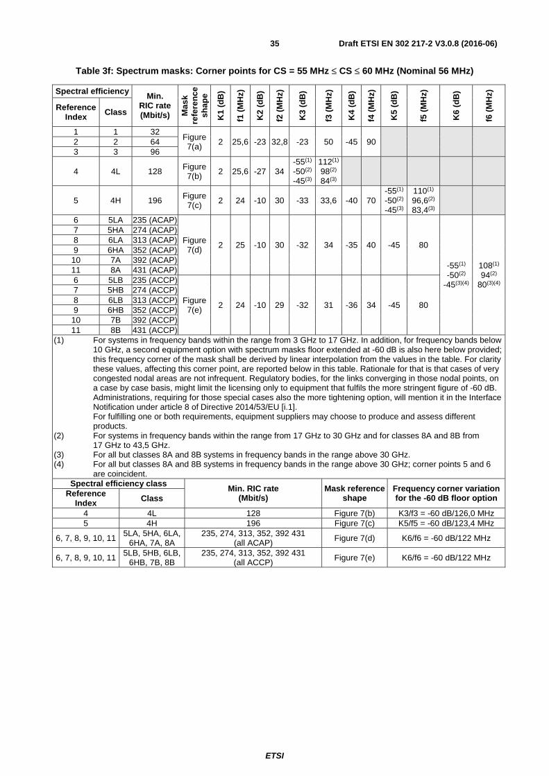
ETSI
Draft ETSI EN 302 217-2 V3.0.8 (2016-06)35
Table 3f: Spectrum masks: Corner points for CS = 55 MHz ≤ CS ≤ 60 MHz (Nominal 56 MHz)
Spectral efficiency Min. RIC rate (Mbit/s) M
ask
refe
ren
ce
shap
e
K1
(dB
)
f1 (
MH
z)
K2
(dB
)
f2 (
MH
z)
K3
(dB
)
f3 (
MH
z)
K4
(dB
)
f4 (
MH
z)
K5
(dB
)
f5 (
MH
z)
K6
(dB
)
f6 (
MH
z)
Reference Index Class
1 1 32 Figure 7(a) 2 25,6 -23 32,8 -23 50 -45 90 2 2 64
3 3 96
4 4L 128 Figure 7(b) 2 25,6 -27 34
-55(1) -50(2) -45(3)
112(1) 98(2) 84(3)
5 4H 196 Figure 7(c) 2 24 -10 30 -33 33,6 -40 70
-55(1) -50(2) -45(3)
110(1) 96,6(2) 83,4(3)
6 5LA 235 (ACAP)
Figure 7(d) 2 25 -10 30 -32 34 -35 40 -45 80
-55(1) -50(2)
-45(3)(4)
108(1) 94(2)
80(3)(4)
7 5HA 274 (ACAP) 8 6LA 313 (ACAP) 9 6HA 352 (ACAP)
10 7A 392 (ACAP) 11 8A 431 (ACAP) 6 5LB 235 (ACCP)
Figure 7(e) 2 24 -10 29 -32 31 -36 34 -45 80
7 5HB 274 (ACCP) 8 6LB 313 (ACCP) 9 6HB 352 (ACCP)
10 7B 392 (ACCP) 11 8B 431 (ACCP)
(1) For systems in frequency bands within the range from 3 GHz to 17 GHz. In addition, for frequency bands below 10 GHz, a second equipment option with spectrum masks floor extended at -60 dB is also here below provided; this frequency corner of the mask shall be derived by linear interpolation from the values in the table. For clarity these values, affecting this corner point, are reported below in this table. Rationale for that is that cases of very congested nodal areas are not infrequent. Regulatory bodies, for the links converging in those nodal points, on a case by case basis, might limit the licensing only to equipment that fulfils the more stringent figure of -60 dB. Administrations, requiring for those special cases also the more tightening option, will mention it in the Interface Notification under article 8 of Directive 2014/53/EU [i.1]. For fulfilling one or both requirements, equipment suppliers may choose to produce and assess different products.
(2) For systems in frequency bands within the range from 17 GHz to 30 GHz and for classes 8A and 8B from 17 GHz to 43,5 GHz.
(3) For all but classes 8A and 8B systems in frequency bands in the range above 30 GHz. (4) For all but classes 8A and 8B systems in frequency bands in the range above 30 GHz; corner points 5 and 6
are coincident. Spectral efficiency class
Min. RIC rate (Mbit/s)
Mask reference shape
Frequency corner variation for the -60 dB floor option Reference
Index Class
4 4L 128 Figure 7(b) K3/f3 = -60 dB/126,0 MHz 5 4H 196 Figure 7(c) K5/f5 = -60 dB/123,4 MHz
6, 7, 8, 9, 10, 11 5LA, 5HA, 6LA, 6HA, 7A, 8A
235, 274, 313, 352, 392 431 (all ACAP) Figure 7(d) K6/f6 = -60 dB/122 MHz
6, 7, 8, 9, 10, 11 5LB, 5HB, 6LB, 6HB, 7B, 8B
235, 274, 313, 352, 392 431 (all ACCP) Figure 7(e) K6/f6 = -60 dB/122 MHz

ETSI
Draft ETSI EN 302 217-2 V3.0.8 (2016-06)36
Table 3g: Spectrum masks: Corner points for CS = 110 MHz to 112 MHz (Nominal 112 MHz) (for bands from 18 GHz up to 42 GHz)
Spectral efficiency Min.
RIC rate (Mbit/s)
Mask reference
shape K1
(dB
)
f1 (
MH
z)
K2
(dB
)
f2 (
MH
z)
K3
(dB
)
f3 (
MH
z)
K4
(dB
)
f4 (
MH
z)
K5
(dB
)
f5 (
MH
z)
K6
(dB
)
f6 (
MH
z)
Reference Index Class
1 1 64 Figure 7(a) 2 51,2 -23 65,6 -23 100 -45 180 2 2 128
3 3 191
4 4L 256 Figure 7(b) 2 51,2 -27 68 -50(1)
-45(2) 196(1) 168(2)
5 4H 392 Figure 7(c) 2 48 -10 60 -33 67,2 -40 140 -50(1)
-45(2) 193,2(1) 166,8(2)
6 5LA 470 (ACAP)
Figure 7(d) 2 50 -10 60 -32 68 -35 80 -45 160
-50(1) -45(2)(3)
188(1) 160(2)(3)
7 5HA 548 (ACAP) 8 6LA 627 (ACAP) 9 6HA 705 (ACAP) 10 7A 784 (ACAP) 11 8A 862 (ACAP) 6 5LB 470 (ACCP)
Figure 7(e) 2 48 -10 58 -32 62 -36 68 -45 160
7 5HB 584 (ACCP) 8 6LB 627 (ACCP) 9 6HB 705 (ACCP) 10 7B 784 (ACCP) 11 8B 862 (ACCP)
(1) For systems in frequency bands within the range from 17 GHz to 30 GHz and for classes 8A and 8B from 17 GHz to 43,5 GHz.
(2) For all but classes 8A and 8B systems in frequency bands in the range above 30 GHz. (3) For all but classes 8A and 8B systems in frequency bands in the range above 30 GHz; corner points 5 and 6 are
coincident.

ETSI
Draft ETSI EN 302 217-2 V3.0.8 (2016-06)37
Table 3h: Spectrum masks: Corner points for CS = 40 MHz
Spectral efficiency Minimum RIC rate (Mbit/s)
Mask reference
shape K1
(dB
)
f1 (
MH
z)
K2
(dB
)
f2 (
MH
z)
K3
(dB
)
f3 (
MH
z)
K4
(dB
)
f4 (
MH
z)
K5
(dB
)
f5 (
MH
z)
K6
(dB
)
f6 (
MH
z)
Reference Index Class
6 5LA 168 (ACAP)
Figure 7(d) 2 18 -10 21,5 -32 24,5 -35 29 -45 57
-55(1) 77(1)
7 5HA 196 (ACAP) 8 6LA 224 (ACAP) 9 6HA 252 (ACAP) 10 7A 280 (ACAP) 11 8A 308 (ACAP) 6 5LB 168 (ACCP)
Figure 7(e) 2 17,2 -10 20,8 -32 22,2 -36 24,5 -45 57
7 5HB 196 (ACCP) 8 6LB 224 (ACCP) 9 6HB 252 (ACCP) 10 7B 280 (ACCP) 11 8B 308 (ACCP)
(1) In addition, for frequency bands in the range below 10 GHz, a second equipment option with spectrum masks floor extended at -60 dB is also here below provided; this frequency corner of the mask shall be derived by linear interpolation from the values in the table. For clarity these values, affecting this corner point, are reported below in this table. Rationale for that is that cases of very congested nodal areas are not infrequent. Regulatory bodies, for the links converging in those nodal points, on a case by case basis, might limit the licensing only to equipment that fulfils the more stringent figure of -60 dB. Administrations, requiring for those special cases also the more tightening option, will mention it in the Interface Notification under article 8 of Directive 2014/53/EU [i.1]. For fulfilling one or both requirements, equipment suppliers may choose to produce and assess different products.
NOTE: Frequency bands with 40 MHz CS are generally intended for high capacity connections. Classes lower than 5L are not considered in the present document.
Spectral efficiency Min. RIC rate
(Mbit/s) Mask reference
shape Frequency corner variation for the -60 dB floor option Reference
Index Class
6, 7, 8, 9, 10, 11 5LA, 5HA, 6LA, 6HA, 7A, 8A
168, 196, 224, 252, 280, 308 (ACAP) Figure 7(d) K6/f6 = -60 dB/87 MHz
6, 7, 8, 9, 10, 11 5LB, 5HB, 6LB,
6HB, 7B, 8B 168, 196, 224, 252, 280, 308
(ACCP) Figure 7(e) K6/f6 = -60 dB/87 MHz
Table 3i: Spectrum masks: Corner points for CS = 62,5 MHz
Spectral efficiency Min.
RIC rate (Mbit/s)
Mask reference
shape K1
(dB
)
f1 (
MH
z)
K2
(dB
)
f2 (
MH
z)
K3
(dB
)
f3 (
MH
z)
K4
(dB
)
f4 (
MH
z)
K5
(dB
)
f5 (
MH
z)
Reference Index C
lass
1 1 35 Figure 8(a) 2 28,7 -18 35 -23 56 -40 90,7 -40 156,3 2 2 71
3 3 106
4 4L 142 Figure 8(b) 2 28,7 -25 37,3 -40 (2) 78,5 -40 156,3
5 4H 219 Figure 8(c) 2 27,5 -10 33,5 -28 37,3 -43 87 -43 156,3
6 5LA 262 Figure 8(d) 2 27,5 -10 33,5
-31 37,7 -45 87
-45 156,3 7 5HA 306 -34 38,5 -45 -45
8 6LA 350 -37 39,1 -45 -45 6 5LB 262
Figure 8(e)
2 26,8 -10 32,4 -31 34,5 -45
87 -45
156,3 7 5HB 306 -34 34,8 -45 -45 8 6LB 350 -37 35 -45 -45

ETSI
Draft ETSI EN 302 217-2 V3.0.8 (2016-06)38
Table 3j: Spectrum masks: Corner points for CS = 125 MHz
Spectral efficiency Min.
RIC rate (Mbit/s)
Mask reference
shape K1
(dB
)
f1 (
MH
z)
K2
(dB
)
f2 (
MH
z)
K3
(dB
)
f3 (
MH
z)
K4
(dB
)
f4 (
MH
z)
K5
(dB
)
f5 (
MH
z)
Reference Index C
lass
1 1 71 Figure 8(a) 3 57,3 -18 70 -23 112 -40 181,3 -40 312,5 2 2 142
3 3 212
4 4L 284 Figure 8(b) 3 57,3 -25 74,5 -40 (2) 157 -40 312,5
5 4H 438 Figure 8(c) 3 55 -10 67 -28 74,5 -43 174 -43 312,5
6 5LA 438 Figure 8(d) 3 55 -10 67
-31 75,8 -45 174
-45 312,5 7 5HA 612 -34 77 -45 -45
8 6LA 700 -37 78,2 -45 -45 6 5LB 438
Figure 8(e) 3 53,5 -10 64,8
-31 69 -45 174
-45 312,5 7 5HB 612 -34 69,5 -45 -45
8 6LB 700 -37 70 -45 -45
Table 3k: Spectrum masks: Corner points for CS = N × 250 MHz (see note 1)
Spectral efficiency Min.
RIC rate (Mbit/s)
Mask reference
shape K1(
dB
)
f1(M
Hz)
K2(
dB
)
f2(M
Hz)
K3(
dB
)
f3 (
MH
z)
K4(
dB
)
f4(M
Hz)
K5(
dB
)
f5(M
Hz)
Reference Index C
lass
1 1 N × 142 Figure 8(a) 3 N × 114,5 -18 N × 140 -23 N × 224 -40 (2) N × 362,5 -40 (2) (1) 2 2 N × 285 (7)
3 3 N × 425 (7)
4 4L N × 570 (7) Figure 8(b)
3 N × 114,5 -25 N × 149 -40 (2) N × 314 -40 (2) (1)
5 4H N x 875 Figure 8(c) 3 N × 110 -10 N × 134 -28 N × 149 -43 (3) N ×348 -43 (3) (1)
6 5LA N x 1 050 (7)
Figure 8(d)
3 N ×110 -10 N × 134 -31 N × 151 -45 (4)
N ×348 -45 (4)
(1) 7 5HA N x 1 225 -34 N × 154 -45 (5) -45 (5) 8 6LA N x 1 400 -37 N × 156 -45 (6) -45 (6) 6 5LB N x 1 050 (7)
Figure 8(e) 3 N × 107 -10 N × 129,5
-31 N × 138 -45 (4) N ×348
-45 (4) (1) 7 5HB N x 1 225 -34 N × 139 -45 (5) -45 (5)
8 6LB N x 1 400 -37 N × 140 -45 (6) -45 (6) (1) For CS ≤ 500 MHz this value is CS × 2,5.
For CS > 500 MHz, this value is variable with CS (MHz) according the formula CS × 1,5 + 500. (2) Attenuation less than -40 + 10log(N) is not required. (3) Attenuation less than -43 + 10log(N) is not required. (4) For N ≥ 2, attenuation less, in dB, than -46 + 10log(N) is not required. (5) For N ≥ 3, attenuation less, in dB, than -49 + 10log(N) is not required. (6) For N ≥ 6, attenuation less, in dB, than -52 + 10log(N) is not required. (7) For class 2 (N = 4), class 3 (N = 5), class 4 (N = 2 and N = 4), classes 5LA and 5LB (N = 1, 2, 3) a minimum RIC
rounded down to closest multiple of 1 Gbit/s rate shall also be considered valid. See table J.2 in annex J for details.
NOTE 1: N can vary from 1 to 8; however, equipment characteristics are not presented for all cases. See table J.2 in annex J for details.
NOTE 2: The 10log(N) value is intended truncated to the first decimal place.

ETSI
Draft ETSI EN 302 217-2 V3.0.8 (2016-06)39
Table 3l: Spectrum masks: Corner points for CS = N × 50 MHz Frequency range 57 GHz to 66 GHz (see note 1)
Spectral efficiency Min.
RIC rate (Mbit/s)
Mask reference
shape K1(
dB
)
f1(M
Hz)
K2(
dB
)
f2(M
Hz)
K3(
dB
)
f3 (
MH
z)
K4(
dB
)
f4(M
Hz)
K5(
dB
)
f5(M
Hz)
Reference Index C
lass
1 1 N × 28,5 (7)
Figure 8(a) 3 N × 22,9 -18 N × 28 -23 N × 44,8 -40 (2) N × 72,5 -40 (2) (1) 2 2 N × 57 3 3 N × 85
4 4L N × 114 Figure 8(b) 3 N × 22,9 -25 N × 29,8 -40 (2) N × 62,8 -40 (2) (1) 5 4H N x 175 Figure 8(c) 3 N × 22 -10 N × 26,8 -28 N × 29,8 -43 (3) N × 69,6 -43 (3) (1)
6 5LA N x 210
Figure 8(d) 3 N × 22 -10 N × 26,8 -31 N × 30,2 -45 (4)
N × 69,6 -45 (4)
(1) 7 5HA N x 245 -34 N × 30,8 -45 (5) -45 (5) 8 6LA N x 280 -37 N × 31,2 -45 (6) -45 (6) 6 5LB N x 210
Figure 8(e) 3 N × 21,4 -10 N × 25,9 -31 N × 27,6 -45 (4)
N × 69,6 -45 (4)
(1) 7 5HB N x 245 -34 N × 27,8 -45 (5) -45 (5) 8 6LB N x 280 -37 N × 28 -45 (6) -45 (6)
(1) For CS ≤ 500 MHz this value is CS × 2,5. For CS > 500 MHz, this value is variable with CS (MHz) according the formula CS × 1,5 + 500.
(2) Attenuation less, in dB, than -40 + 10log(N/5) is not required. (3) Attenuation less, in dB, than -43 + 10log(N/5) is not required. (4) For N ≥ 10, attenuation less, in dB, than -46 + 10log(N/5) is not required. (5) For N ≥ 15, attenuation less, in dB than -49 + 10log(N/5) is not required. (6) For N ≥ 30, attenuation less, in dB, than -52 + 10log(N/5) is not required. (7) For N > 4 rounded down to the lower Mbit/s integer. NOTE 1: N can vary from 1 to 40; however, equipment characteristics are not presented for all cases. See table H.2 in
annex H for details. NOTE 2: The 10log(N/5) value is intended truncated to the first decimal place.
Table 3m: Spectrum masks: Corner points for CS = N × 30 MHz Frequency range 64 GHz to 66 GHz (see note 1)
Spectral efficiency Min.
RIC rate (Mbit/s)
Mask reference
shape K1(
dB
)
f1(M
Hz)
K2(
dB
)
f2(M
Hz)
K3(
dB
)
f3 (
MH
z)
K4(
dB
)
f4(M
Hz)
K5(
dB
)
f5(M
Hz)
Reference Index C
lass
1 1 N × 17 Figure 8(a) 3 N × 13,8 -18 N × 16,8 -23 N × 26,9 -40 (2) N × 43,5 -40 (2) (1) 2 2 N × 34
3 3 N × 51
4 4L N × 68 Figure 8(b) 3 N × 13,8 -25 N × 17,9 -40 (2) N × 37,7 -40 (2) (1) 5 4H N x 105 Figure 8(c) 3 N × 13,2 -10 N × 16,1 -28 N × 17,9 -43 (3) N × 41,8 -43 (3) (1)
6 5LA N x 126
Figure 8(d) 3 N × 13,2 -10 N × 16,1 -31 N × 18,1 -45 (4)
N × 41,8 -45 (4)
(1) 7 5HA N x 147 -34 N × 18,5 -45 (5) -45 (5) 8 6LA N x 168 -37 N × 18,7 -45 (6) -45 (6) 6 5LB N x 126
Figure 8(e) 3 N × 12,7 -10 N × 15,6 -31 N × 16,6 -45 (4)
N × 41,8 -45 (4)
(1) 7 5HB N x 147 -34 N × 16,7 -45 (5) -45 (5) 8 6LB N x 168 -37 N × 16,8 -45 (6) -45 (6)
(1) For CS ≤ 500 MHz this value is CS × 2,5. For CS > 500 MHz, this value is variable with CS (MHz) according the formula CS × 1,5 + 500.
(2) Attenuation less than -40 + 10log(N/8) is not required. (3) Attenuation less than -43 + 10log(N/8) is not required. (4) For N ≥ 17, attenuation less, in dB, than -46 + 10log(N/8) is not required. (5) For N ≥ 25, attenuation less, in dB, than -49 + 10log(N/8) is not required. (6) For N ≥ 50, attenuation less, in dB, than -52 + 10log(N/8) is not required. NOTE 1: N can vary from 1 to 33 for FDD systems and from 1 to 66 for TDD systems; however, equipment
characteristics are not presented for all cases. See table I.2 in annex I for details. NOTE 2: The 10log(N/8) value is intended truncated to the first decimal place.

ETSI
Draft ETSI EN 302 217-2 V3.0.8 (2016-06)40
4.2.4 Discrete CW components exceeding the spectrum mask limit
4.2.4.1 Discrete CW components at the symbol rate
In case discrete CW components at the symbol rate exceed the spectrum mask, the power level (at reference point C' or at point B' if C' of figure 1 of ETSI EN 302 217-1 [4] is not available) of spectral lines at a distance from the carrier (or from each aggregated channel carrier for channels-aggregation equipment, or each sub-carrier in multi-carrier equipment) centre frequency equal to the symbol rate shall be below the mean power level of the carrier by more than:
• 23 dB for classes 1, 2
• 29 dB for class 3
• 37 dB for classes 4L, 4H, 5LA, 5HA, 6LA, 6HA, 7A, 8A
• 43 dB for classes 5L, 5LB, 5H, 5HB
• 49 dB for classes 6L, 6LB, 6H, 6HB
• 55 dB for classes7, 7B, 8, 8B
When channels-aggregation equipment is concerned see also clause O.4.
4.2.4.2 Other discrete CW components exceeding the spectrum mask limit
In case CW components, other than the residual of the unmodulated carrier (sub-carriers) or those at the symbol rate, exceed the spectrum mask given in the relevant annexes, an additional allowance is given as follows.
Let CSmin (MHz) be a parameter, dependent on the frequency band and the system under consideration defined in table 4 and the result of the formula:
(dB) )10min
log10( −hIFbandwidt
CS
be calculated, where IF bandwidth (IFbw) is the recommended resolution bandwidth set out in table 6.
If the result is ≤ 0 dB, no additional allowance is then permitted.
If the result is > 0 dB the power aggregation of the lines falling, outside the operating CS, within any CSmin width where the spectrum mask is defined shall not exceed the ratio in dB calculated by the following formula:
10min
log1010log101
10 −≤∑=
= hIFbandwidt
CSni
i
xi
Where Xi is the mask excess (in dB) of the ith of n lines, falling in the CSmin width (see examples 1 and 2 and figure 9).
EXAMPLE 1: Figure 9 example applied to the 10,7 GHz to 11,7 GHz band (CSmin = 10 MHz; IFbw = 30 kHz) shows that the same effect can be obtained by: a) one single line, e.g. in leftmost CSmin slot, exceeding the mask by up to 15,2 dB; b) two lines (n = 2), e.g. in next CSmin slot, exceeding the mask e.g. up to X1 = 14 dB and X2 = 9 dB, respectively; c) three lines (n = 3), e.g. in rightmost CSmin width, exceeding the mask e.g. up to X1 = 12 dB, X2 = 11 dB and X3 = 7 dB, respectively.
EXAMPLE 2: Figure 9 example applied to the 71 GHz to 86 GHz band (CSmin = 250 MHz; IFbw = 2 MHz) shows that the same effect can be obtained by: a) one single line, e.g. in leftmost CSmin slot, exceeding the mask by up to 11 dB; b) two lines (n = 2), e.g. in next CSmin slot, exceeding the mask e.g. up to X1 = 9 dB and X2 = 6,5 dB, respectively; c) three lines (n = 3), e.g. in rightmost CSmin width, exceeding the mask e.g. up to X1 = 9 dB, X2 = 4,7 dB and X3 = 2 dB, respectively.
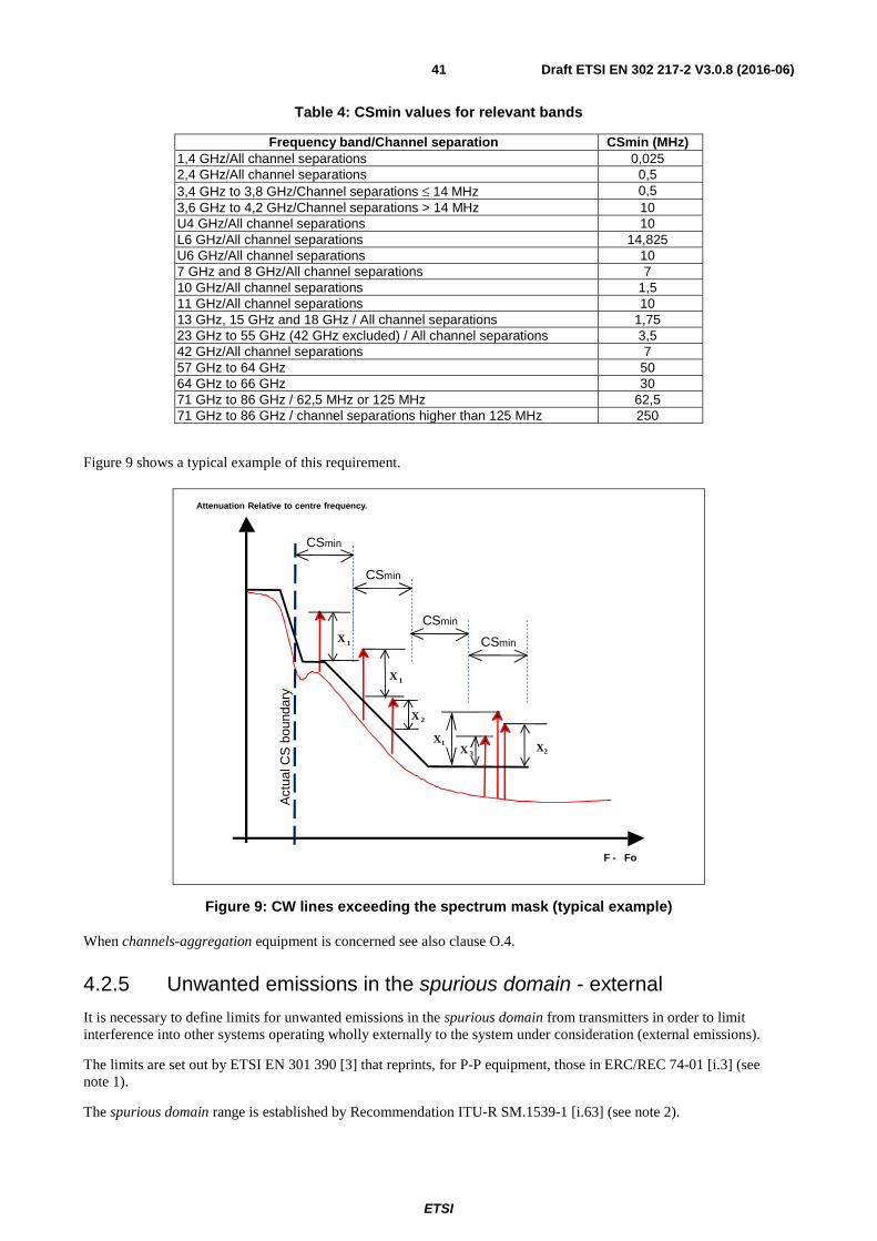
ETSI
Draft ETSI EN 302 217-2 V3.0.8 (2016-06)41
Table 4: CSmin values for relevant bands
Frequency band/Channel separation CSmin (MHz) 1,4 GHz/All channel separations 0,025 2,4 GHz/All channel separations 0,5 3,4 GHz to 3,8 GHz/Channel separations ≤ 14 MHz 0,5 3,6 GHz to 4,2 GHz/Channel separations > 14 MHz 10 U4 GHz/All channel separations 10 L6 GHz/All channel separations 14,825 U6 GHz/All channel separations 10 7 GHz and 8 GHz/All channel separations 7 10 GHz/All channel separations 1,5 11 GHz/All channel separations 10 13 GHz, 15 GHz and 18 GHz / All channel separations 1,75 23 GHz to 55 GHz (42 GHz excluded) / All channel separations 3,5 42 GHz/All channel separations 7 57 GHz to 64 GHz 50 64 GHz to 66 GHz 30 71 GHz to 86 GHz / 62,5 MHz or 125 MHz 62,5 71 GHz to 86 GHz / channel separations higher than 125 MHz 250
Figure 9 shows a typical example of this requirement.
F - Fo
Attenuation Relative to centre frequency.
X 1
X1 X2
X 2
X 3
CSmin
CSmin
CSmin
CSmin
Act
ual C
S b
ound
ary
X 1
Figure 9: CW lines exceeding the spectrum mask (typical example)
When channels-aggregation equipment is concerned see also clause O.4.
4.2.5 Unwanted emissions in the spurious domain - external
It is necessary to define limits for unwanted emissions in the spurious domain from transmitters in order to limit interference into other systems operating wholly externally to the system under consideration (external emissions).
The limits are set out by ETSI EN 301 390 [3] that reprints, for P-P equipment, those in ERC/REC 74-01 [i.3] (see note 1).
The spurious domain range is established by Recommendation ITU-R SM.1539-1 [i.63] (see note 2).

ETSI
Draft ETSI EN 302 217-2 V3.0.8 (2016-06)42
The equipment shall comply with the requirements of clause 4.1 of ETSI EN 301 390 [3] for any setting of ATPC and RTPC (if any).
NOTE 1: ERC/REC 74-01 [i.3] based on Recommendation ITU-R SM.329-12 [i.62] and Recommendation ITU-R F.1191-3 [i.54] give the applicable definitions.
NOTE 2: According to Recommendation ITU-R SM.1539-1 [i.63] and Appendix 3 of the ITU Radio Regulations [7], the boundary where the spurious domains begins, is considered to be offset from the nominal centre frequency of the emission by ±250 % of the relevant Channel Separation (CS), as far as they do not exceeded 500 MHz. Beyond this value the boundary is evaluated as: ±(500 MHz + 1,5 × CS). When a CS is not defined (e.g. bandwidth size is left free), the actual occupied bandwidth (i.e. the 99 % of power of the emission) is used.
When channel-aggregation equipment are concerned, each aggregated-channel emission shall be compliant to the unwanted emissions in the spurious domain limit applied to its own relevant channel when the second channel is operating within the manufacturer prescription. Clause O.4.1 describes the general assessment test cases and clause O.4.2 the possible specific joint envelope limits definition for single port equipment case.
The limits are applicable at reference point C' or at point B' (see figure 1 of ETSI EN 302 217-1 [4]) if C' is not available.
4.2.6 Dynamic Change of Modulation Order
For mixed-mode systems (including bandwidth adaptive operation, if any), the transient behaviour of the transmitter, when a transition from any dynamically activated modulation format (and/or any bandwidth adaptive operation), to any other occurs, shall meet the specification of the declared Reference mode (i.e. reference spectral efficiency class and, when bandwidth adaptive system are concerned, widest operating bandwidth) applicable for each relevant CS for:
• the spectral power density mask (see clause 4.2.3.2) with the flat in-band level (i.e. the "K1" mask values) raised to +3 dB for all systems;
• its associated CW spectral lines allowance (see clause 4.2.4).
In this case, the 0 dB reference of the spectral power density mask, shall be kept fixed as the one obtained with the Reference mode in static conditions, except for the case of bandwidth adaptive modulation in which the 0 dB reference level can be exceeded by a factor of 10log(BWmax / BWmin), but not more than 6 dB (i.e. 4 times band reduction).
The supplier shall declare, for each CS, among the number of possible equipment operational modes, the possible Reference mode(s) (among which to select the one used for licensing procedures), which the system is capable to fulfil. For each Reference mode, the supplier shall define the corresponding equipment settings (e.g. the output power) for meeting the requirements (e.g. spectrum mask) of that Reference mode. See also clause P.2.
When channels-aggregation equipment is concerned, the dynamic change of modulation of the aggregated channels shall be activated according the normal operating conditions (e.g. synchronous or non-synchronous transitions) specified by the manufacturer.
Such dynamic transitions shall also not cause the specifications for unwanted emissions in the spurious domain (see clause 4.2.5) to be exceeded.
4.2.7 Radio frequency tolerance
For the purpose of the present document the frequency tolerance is as defined in article 1.151 of the Radio Regulations [7] as "The maximum permissible departure by the centre frequency of the frequency band occupied by an emission from the assigned frequency".
When operating in the environmental profile declared by the supplier, the maximum allowable RF frequency tolerance shall not exceed, by any reason, the following limits:
Equipment operating in bands below 3 GHz: No requirement, the frequency tolerance shall be included in the applicable spectral density masks.
Equipment operating in the bands above 57 GHz: ±50 ppm

ETSI
Draft ETSI EN 302 217-2 V3.0.8 (2016-06)43
All other cases: ±15 ppm
For conformity test purpose the supplier shall state the guaranteed short-term part and the expected ageing part.
4.2.8 Emission limitations outside the allocated band
In some frequency bands, for limiting the unwanted emissions possibly exceeding the allocated band boundaries, additional limitations are required. When necessary, they are given in the relevant annex.
4.3 Receiver requirements
4.3.0 General: System loading
All measurements, when applicable, shall be carried out with the transmitters loaded with test signals defined in clause 4.2.0.
Equipment may provide BB traffic interfaces either single (e.g. 1 × 100baseT) or multiple (e.g. 10 × 10baseT); BER and C/I performance tests will be carried only on one interface. However, when systems are configured as multi-channels (including similar use of channels-aggregation equipment) clause O.3 describes the necessary variation of the assessment methodology.
4.3.1 Unwanted emissions in the spurious domain - external
It is necessary to define limits for unwanted emissions in the spurious domain from receivers in order to limit interference into other systems operating wholly externally to the system under consideration (external emissions).
The limits are set out in ETSI EN 301 390 [3] that reprints, for P-P equipment, those in ERC/REC 74-01 [i.3] (see note).
No exclusion band around operating frequency (i.e. that inside the spurious domain boundaries described in note 2 to clause 4.2.5 for TX limits) is considered.
Those limits are applicable at reference point C or at point B (see figure 1 of ETSI EN 302 217-1 [4]) if C is not available.
For channel aggregation systems the same principles defined in clause 4.2.5 and clause O.4 apply.
NOTE: ERC/REC 74-01 [i.3] based on Recommendation ITU-R SM.329-12 [i.62] and Recommendation ITU-R F.1191-3 [i.54] gives the applicable definitions.
4.3.2 BER as a function of receiver input signal level RSL
All parameters are referred to reference point C (for systems with a simple duplexer) or B (for systems with a multi-channel branching system). Losses in RF couplers (possibly used for protected systems) are not taken into account in the limits specified below.
When packet data transmission is considered, any BER requirements shall be transformed into FER requirements according to the rules given in clause N.3.
Equipment working at the relevant declared RSL thresholds shall produce a BER equal to or less than the corresponding values (i.e. 10-6 and 10-8 for systems with minimum RIC ≤ 100 Mbit/s, or 10-6 and 10-10 for systems with minimum RIC > 100 Mbit/s).
The supplier shall declare the RSL threshold(s) (dBm) for the relevant BER values (i.e. 10-6 and 10-8 or 10-10), which shall not be worse than the corresponding RSL upper bound values indicated in the tables of the relevant annex(es).
When multi-carrier systems are concerned, the RSL is intended as the total power integrated for all sub-carriers and, when multiple payload interfaces are also provided (at reference points X', X), the BER shall be evaluated on the worst case interface.
ETSI
Draft ETSI EN 302 217-2 V3.0.8 (2016-06)44
EXAMPLE: In case of two equal sub-carriers, the RSL of each sub-carrier is intended to be 3 dB less than the total RSL power specified in the present document.
When channels-aggregation equipment are concerned, the limits are intended as:
a) when independent baseband signal interconnections according clause O.3.1 are provided, with the other aggregated channel (that not under test) operating, according manufacturer prescription, on the second adjacent CS frequency (for single-port equipment) or the first adjacent CS frequency (for dual-port equipment) with more demanding declared differential RSL ratio between the two channels (e.g. set through different RTPC levels), (see clause 4.1.1);
b) when common baseband signal interconnections according clause O.3.2 are provided, see prescriptions in table O.1 of annex O;
c) for single-port only, in the event that the device combining the two received signals is integrated in the equipment, the RSL thresholds specified in annexes B to J will be relaxed by the combining device loss (e.g. 3 dB for a hybrid coupler).
When equipment can be optionally configured according conditions a) or b) above, the a) conditions shall be the one used for conformance assessment.
NOTE 1: For mixed-mode systems, these requirements apply only for the assessment of essential requirements under article 3.2 of the Directive 2014/53/EU [i.1]. It is assumed that, when operational in the field, the switchover among different modes (or different bandwidth for bandwidth adaptive systems in 71 GHz to 86 GHz) will happen at suitable RSL thresholds defined by the manufacturer or the operator. See clause P.2.
NOTE 2: Actual RSL threshold for link budget definition may be defined by the supplier, generally set to a BER between 10-6 and 10-3, according to the type of traffic and quality of service to be provided.
NOTE 3: When planning very short links, where propagation would require fade margins limited to few dB for fulfilling the availability and the SES error performance objectives, a minimum link budget should nevertheless be defined for fulfilling also the "background block error ratio" (BBER) error performance objective. The required RSL for the reaching the RBER (established in ETSI EN 302 21781 [4]) should be considered.
4.3.3 Receiver selectivity
4.3.3.1 Introduction
In general, the selectivity is the ability of the receiver to reduce the impact of interfering signals outside the wanted signal bandwidth. In the present document it is specified in terms of receiver sensitivity degradation in presence of like signals of predefined C/I ratio in the adjacent channels and to generic unmodulated (CW interference) signal anywhere in a large portion of the spurious domain (blocking and spurious response requirement).
Co-channel interference sensitivity is also used as reference for deriving the selectivity; informative annex R details the methodology on how to translate C/I requirements into selectivity-like figures.

ETSI
Draft ETSI EN 302 217-2 V3.0.8 (2016-06)45
4.3.3.2 Co-channel "external", first and second adjacent channel interference sensitivity
4.3.3.2.1 Requirements basics
In clause 4.3.3.2 and its subclauses all requirements and their definitions are intended with wanted and unwanted signals of same equipment type, operating on identical or corresponding adjacent centre frequencies according to the relevant ECC recommendations, on same CS size and preset for same nominal emissions (in terms of actual modulation formats, RIC and, unless specifically defined, output power level).
The co-channel "external" interference is considered to be that given by a like signal completely uncorrelated with the one under test. There are different requirements for "internal" interference given by the transmitters in systems implementing frequency reuse (see note); however, the latter requirements are not considered relevant to essential requirements under article 3.2 of Directive 2014/53/EU [i.1] and are set out in ETSI EN 302 217-1 [4].
NOTE: E.g. implementing Cross-polar Interference Canceller (XPIC) in CCDP operation or Multiple Input-Multiple Output (MIMO) technique.
The first and second adjacent channel interference is that given by a like signal completely uncorrelated with the one under test removed from its nominal centre frequency by one CS frequency according the band specific provided in the relevant annexes from B through J. The requirement is intended to be separately met by both upper and lower CS interference cases.
All Carrier to Interference ratio (C/I) settings are applied to reference point C (for systems for single channel applications) or B (for systems with multi-channel branching system).
When channels-aggregation equipment are concerned, the limits are intended as:
a) when independent baseband signal interconnections according clause O.3.1 are provided:
a1) for single-port equipment, with the other aggregated channel (that not under test) operating, according manufacturer prescription, on the second adjacent CS frequency. For both adjacent channels requirement the interference shall be opposite to the aggregated channel not under test.
a2) for dual-port equipment with the other aggregated channel (that not under test) operating, according manufacturer prescription, on the first adjacent CS frequency with more demanding declared differential RSL ratio to that under test (e.g. set through different RTPC levels), see also clause 4.1.1.
b) when common baseband signal interconnections according clause O.3.2 are provided, see prescriptions in table O.1 of annex O.
When equipment can be optionally configured according conditions a) or b) above, the a) conditions shall be the one used for conformance assessment.
4.3.3.2.2 Limits for co-channel and first adjacent channel
The limits of Carrier to Interference ratio (C/I) in case of co-channel and first adjacent channel interference shall be as specified in the relevant tables of annexes B to J, giving maximum C/I values for 1 dB and 3 dB degradation of the RSL limits declared by the supplier for a BER ≤ 10-6 in clause 4.3.2.
The format of such tables is given in table 5.
NOTE: For some equipment in annex B only 1 dB degradation is required. In those cases a requirement for second adjacent channel interference is also given.
For adjacent channel interference, the requirement shall be met independently on upper and lower adjacent interference.

ETSI
Draft ETSI EN 302 217-2 V3.0.8 (2016-06)46
Table 5: Co-channel and 1st adjacent channel interference sensitivity table format
Spectral efficiency Minimum RIC
rate (Mbit/s)
Channel separation
(MHz)
C/I for BER ≤ 10-6 RSL degradation of 1 dB or 3 dB
Reference Index Class
Co-channel Interference
adjacent channel interference
1 dB 3 dB 1 dB 3 dB
NOTE: Actual values for this template are found in the specific frequency band annexes.
4.3.3.2.3 Limits for second adjacent channel interference
For equipment in bands covered by annex B, the limits are reported in that annex.
For equipment operating in other bands, the limits of Carrier to Interference ratio (C/I) in case of second adjacent channel interference shall be declared by the manufacturer (see note). That limit shall be in term of maximum C/I values for 1 dB degradation of the RSL limits declared by the manufacturer for a BER ≤ 10-6 in clause 4.3.2 and shall not be less demanding than the level of C/I for first adjacent channel for the same 1 dB degradation required in clause 4.3.3.2.
The less demanding level of C/I ratio (i.e. equal to the first adjacent C/I ratio requirement) is automatically obtained as physical consequence of compliance to first adjacent channel interference in clause 4.3.3.2.2 and to the more demanding CW spurious interference sensitivity in clause 4.3.3.3. Therefore, compliance shall be guaranteed, but specific assessment procedure of this functionality is not required.
When manufacturer declaration implies a more demanding C/I ratio (see note), formal assessment shall be carried out with procedure similar to that for first adjacent channel interference sensitivity.
NOTE: It is intended that the declared C/I value is within a range coherent with spectrum mask requirement in the present document. Clause R.2.2 gives the appropriate technical background.
4.3.3.3 CW spurious interference (blocking & spurious response rejection)
This test is designed to identify specific frequencies at which the receiver may have a spurious response; e.g. image frequency, harmonics of the receive filter, etc. The test is not intended to imply a relaxed specification at all out of band frequencies elsewhere specified in ETSI EN 302 217 series (e.g. image(s) rejection specified in ETSI EN 302 217-1 [4]).
Two alternative methods are possible for manufacturer selection.
Method 1 (similar to the Co-channel/adjacent channel test methods)
For a receiver operating at 1 dB above the RSL threshold for a BER ≤ 10-6 as declared by the supplier in clause 4.3.2, the introduction of a CW interferer at a level specified by ETSI EN 301 390 [3], but not exceeding the maximum input level (RSL) limit for BER = 10-6 defined in clause 7.4.1 of ETSI EN 302 217-1 [4], with respect to the wanted signal and at any frequency up to the relevant upper and lower frequency limits derived from the table set out in clause 7.1 of ETSI EN 301 390 [3], but excluding frequencies either side of the wanted frequency by up to 250 % of the separation between channels using the same polarization, shall not result in a BER greater than 10-6.
Method 2
For a receiver operating at the RSL declared by the supplier in clause 4.3.2 for a BER ≤ 10-6 threshold, the introduction of a CW interferer at a level specified by ETSI EN 301 390 [3], but not exceeding the maximum upper RSL limit for BER = 10-6defined in ETSI EN 302 217-1 [4], clause 6.4.1, with respect to the wanted signal and at any frequency up to the relevant upper and lower frequency limits derived from the table set out in clause 7.1 of ETSI EN 301 390 [3], but excluding frequencies either side of the wanted frequency by up to 250 % of the separation between channels using the same polarization, shall not result in a BER greater than 10-5.

ETSI
Draft ETSI EN 302 217-2 V3.0.8 (2016-06)47
Common special provisions
When multi-carrier systems are concerned, the wanted signal level is intended as the total power integrated for all sub-carriers and, when multiple payload interfaces are also provided (at reference points X', X), the BER shall be evaluated on the worst case interface.
When channels-aggregation equipment are concerned, the limits are intended as:
a) when independent baseband signal interconnections according clause O.3.1 are provided, with the other aggregated channel (that not under test) operating, according manufacturer prescription, on the channel frequency with more demanding differential RSL ratio to that under test (e.g. set through different RTPC levels), (see clause 4.1.1).
b) when common baseband signal interconnections according clause O.3.2 are provided, see prescriptions in table O.1 of annex O.
When equipment can be optionally configured according conditions a) or b) above, the a) conditions shall be the one used for conformance assessment.
4.4 Antenna Characteristics
4.4.1 Integral antennas or dedicated antennas
4.4.1.1 Introduction
This clause applies to all equipment specified in annexes B to J where either an integral antenna or a dedicated antenna is provided. Antenna characteristics relevant to article 3.2 of the Directive 2014/53/EU [i.1] are specified, for the relevant frequency band and antenna class, in ETSI EN 302 217-4 [5].
RPE, gain (including tolerances around the nominal declared value) and XPD of antennas are essential parameters for both transmitter and receiver side as antenna performance is deemed equally essential to both transmit and receive direction.
4.4.1.2 Radiation Pattern Envelope (Off-axis EIRP density)
Co-polar and cross-polar Radiation Pattern Envelope (RPE) is considered essential parameter for meeting requirements of article 3.2 of the Directive 2014/53/EU [i.1]; limits that shall apply are:
• for bands in the range 1 GHz to 3 GHz: any class in clause 4.4.2 of ETSI EN 302 217-4 [5] (see note).
• for bands above 3 GHz: only class 2 or higher classes in clauses from 4.4.3 to 4.4.9 of ETSI EN 302 217-4 [5] (see note).
For bands in the range from 57 GHz to 66 GHz, because simplified or no frequency co-ordination procedures are generally applied, cross-polar RPE is not considered as essential parameter for meeting requirements of article 3.2 of the Directive 2014/53/EU [i.1], even if the antenna is actually dual polarized. Values given in, for completeness, in clause 4.2.9 of ETSI EN 302 217-4 [5] should be considered for reference purposes.
NOTE: It is assumed that the equipment supplier declares which class the antenna meets.
4.4.1.3 Antenna gain
The antenna gain and tolerance is considered essential parameter for meeting requirements of article 3.2 of the Directive 2014/53/EU [i.1].
According clause 4.6 of ETSI EN 302 217-4 [5] the supplier shall declare the nominal gain and its tolerance (see note).
NOTE: Gain tolerance is generally considered to be equally distributed across the nominal value (i.e. ± dB)
Minimum gain requirements for specific bands are also referred in the relevant annexes of the present document.

ETSI
Draft ETSI EN 302 217-2 V3.0.8 (2016-06)48
4.4.1.4 Antenna Cross-Polar Discrimination (XPD)
The antenna cross-polar discrimination (XPD) is considered essential parameter for meeting requirements of article 3.2 of the Directive 2014/53/EU [i.1]; minimum required limits are those of XPD class 1 defined in clause 4.5 of ETSI EN 302 217-4 [5].
For bands in the range from 57 GHz to 66 GHz, where simplified or no frequency co-ordination procedures are generally applied, XPD is not considered as essential parameter for meeting requirements of article 3.2 of the Directive 2014/53/EU [i.1], even if the antenna is actually dual polarized. Values given in clause 4.5 of ETSI EN 302 217-4 [5] for that range should be considered for reference purposes only.
4.4.2 Guidelines for stand-alone antennas
When equipment is placed upon the market without an antenna, and the user therefore sources a stand-alone antenna from the marketplace, the equipment manufacturer should consider that:
a) Under the obligation of article 10, recital 8 of the Directive 2014/53/EU [i.1]: "Manufacturers shall ensure that the radio equipment is accompanied by instructions…Instructions shall include the information required to use radio equipment in accordance with its intended use".
b) Under the provisions of article18, recital 2 the EU Declaration of conformity: "… shall have the model structure set out in Annex VI, shall contain the elements set out in that Annex and…". Then, annex VI recital 8 includes: "where applicable, description of accessories and components, including software, which allow the radio equipment to operate as intended and covered by the EU declaration of conformity".
Consequently, the equipment manufacturer should provide sufficient guidance that the combination of equipment and stand-alone antenna continues to meet the requirements of the Directive 2014/53/EU [i.1]. Therefore, the equipment manufacturer, where the use of stand-alone antenna is possible, should include in the equipment instruction (see article 10, recital 8 of the Directive 2014/53/EU [i.1]) the statement that the equipment can operate as intended only if connected to antenna with characteristics conforming to:
• for bands in the range 1 GHz to 3 GHz: RPE of any class according clause 4.4.2 of ETSI EN 302 217-4 [5] and XPD class 1 according clause 4.5.2 of ETSI EN 302 217-4 [5];
• for bands above 3 GHz: RPE of class 2 or higher classes according to clause 4.4.3 to clause 4.4.9 of ETSI EN 302 217-4 [5] and XPD class 1 according clause 4.5.2 of ETSI EN 302 217-4 [5];
• minimum gain according the minimum value, if any required, in the relevant band annexes of the present document.
5 Testing for compliance with technical requirements
5.1 Environmental and other conditions for testing
5.1.1 Environmental conditions
The equipment shall comply with all the requirements of the present document at all times when operating within the boundary limits of the operational environmental profile declared by the supplier, including the limits of any primary/secondary power supply external to the equipment under assessment.
Boundary limits of environmental climatic conditions, which are part of the environmental profile, may be determined by the environmental class of the equipment according to the guidance given in clause 4.4 of ETSI EN 301 126-1 [1].
Tests defined in the present document shall be carried out at representative points within the boundary limits of the declared operational environmental profile.

ETSI
Draft ETSI EN 302 217-2 V3.0.8 (2016-06)49
Any test, requested to generate the test report and/or declaration of conformity in order to fulfil any Conformity assessment procedure with respect to the Directive 2014/53/EU [i.1] shall be carried out:
a) For radio equipment, with respect to the same principles and procedures, for reference and extreme conditions, set out in clause 4.4 of ETSI EN 301 126-1 [1] for climatic conditions and in table 1 of ETSI EN 301 126-1 [1] and clauses 5.2 and 5.3 of the present document for power supply conditions. The requirement to test at reference or extreme conditions is set out in clauses 5.2 and 5.3 of the present document according to the principles for similar requirements set out in ETSI EN 301 126-1 [1].
b) For DFRS antennas (directional phenomena of clause 4.4 of the present document), at reference environmental conditions of the test field according to clause 4.1 of ETSI EN 301 126-3-1 [2].
5.1.2 Test interpretation and measurement uncertainty
Test reports should be produced according to the procedure for compiling the technical documentation set out in article 21 and annex V of the Directive 2014/53/EU [i.1].
Interpretation of the results recorded in a test report (of the measurements described in the present document) shall be as follows:
• For the purposes of test, the limits in the present document are based on the "shared risk" of measurement uncertainty, e.g. if a measurement meets the requirements of the standard, even if it is within the calculated measurement uncertainties, it shall be deemed compliant with the measurement parameter.
• If it fails to meet the requirements of a standard, even within measurement uncertainty, it is deemed to be not compliant with the measurement parameter.
Measurement uncertainty calculations should be based on the latest available ETSI guidelines (e.g. ETSI TR 100 028 [i.29] and, when radiated measurements are concerned, ETSI TR 102 215 [i.32]).
In conclusion:
• the measured value related to the corresponding limit will be used to decide whether an equipment meets the requirements of the present document;
• the value of the measurement uncertainty for the measurement of each parameter should be included in the test report.
5.1.3 Other basic conditions
The supplier shall identify the chosen system profile, selected from tables X.2 (where X = B, C, D, E, F, G, H, I and J represents the relevant annex).
The system shall be loaded with a continuous data stream at the declared RIC rate (user's interfaces shall be loaded accordingly) and no loss of data shall be experienced (see note).
NOTE: As further guidance, ETSI TR 102 565 [i.34] states that the accumulated data rate of all interfaces at X/X' reference point(s) should not be the limiting bottleneck, but the capacity of the radio link. In case that the portion between X/X' and Z/Z' is able to provide control mechanisms for the data stream at X/X', these mechanisms should be configured such that the radio link capacity determines the accepted data rate at X/X'. Figure 1 of ETSI EN 302 217-1 [4] defines X/X' and Z/Z' reference interfaces on the generic system block diagram; further guidance can be found in figure 2 of ETSI TR 102 565 [i.34].
When channels-aggregation equipment are concerned, both aggregated channels shall be loaded and, when not elsewhere specified, transmitting/receiving the intended capacity.
Systems can, in principle, be fully loaded only in the direction under test; however, when bidirectional systems are assessed, the TX co-located to the RX under test, shall at least transmit its modulated carrier at maximum possible power suitably terminated at the antenna port (reference points C' defined in figure 1 of ETSI EN 302 217-1 [4]); however, it may be muted when RX unwanted emissions are tested.

ETSI
Draft ETSI EN 302 217-2 V3.0.8 (2016-06)50
When equipment operate with intermittent emissions (i.e. time periods when no net user capacity is transmitted, either for internal system purpose or real transmitter shut down) care should be taken that the tests are not affected by those system shut down periods.
The tests for radio equipment and antennas may be made separately, whenever appropriate (see clause 4.1.1).
5.2 Test methods for the transmitter
5.2.0 General test summary
The tests, carried out to generate the test report in order to fulfil any conformity assessment procedure with respect to the Directive 2014/53/EU [i.1], shall be carried out at climatic conditions referred to in table 6 and, when applicable for equipment with integral or dedicated antenna, in table 9.
Table 6 indicates the different clauses applicable, for a given parameter, to the requirement, the test clause in the present document and the corresponding test method in the base test document ETSI EN 301 126-1 [1].
Table 6: Transmitter parameters, test clauses and conditions
Clause (see note 2)
Parameter (see note 2)
ETSI EN 301 126-1 [1] reference clause
for the test methods
Climatic conditions (see note 1)
Channels to be tested
(see note 4) Other specific conditions
Ref Extreme B = Bottom M = Middle
T = Top
5.2.1.1 Maximum power
5.2.1 (transmitter
power) 6.3 of
ETSI EN 301 126-3-1 [2] (EIRP)
X X BMT See note 3
5.2.1.2 Combined maximum TX power output
and EIRP
5.2.1 (transmitter
power) 6.3 of
ETSI EN 301 126-3-1 [2] (EIRP)
X BMT
5.2.1.3 Transmitter output power
tolerance
5.2.1 X X BMT See note 3
5.2.2
Transmitter power and frequency
control
5.2.2.1.1
Automatic Transmit
Power Control (ATPC)
5.2.3 and 5.2.6 X M
5.2.2.1.2
Remote Transmit
Power Control (RTPC)
5.2.4 and 5.2.6 X BMT
Shall be carried out at three operating conditions (lowest, medium, and highest delivered power) of the RTPC power range and with ATPC (if any) set to maximum nominal power
5.2.2.1.3 Remote
Frequency Control (RFC)
5.2.7 and 5.2.6 X BMT
Tests shall be carried for RFC setting procedure for three frequencies (i.e. frequency settings from lower to centre, centre to higher and back to the lower frequency within the covered range)
5.2.3 RF Spectrum Mask 5.2.6 X X BMT See note 3

ETSI
Draft ETSI EN 302 217-2 V3.0.8 (2016-06)51
Clause (see note 2)
Parameter (see note 2)
ETSI EN 301 126-1 [1] reference clause
for the test methods
Climatic conditions (see note 1)
Channels to be tested
(see note 4) Other specific conditions
Ref Extreme B = Bottom M = Middle
T = Top
5.2.4
Discrete CW components
exceeding the spectrum
masks limits
5.2.8 X X BMT See note 3
5.2.5
Unwanted emissions in the spurious
domain- external
5.2.9 X BMT
The tests shall be carried out with ATPC, if any, set to maximum available power and RTPC, if any, set at minimum attenuation. Actual test shall be limited to the practical frequency range set out by clause A.1 of ETSI EN 301 390 [3]
5.2.6
Dynamic Change of Modulation
Order
- X X BMT
see note 3 Required for mixed-mode systems only (including bandwidth adaptive systems), according clause 5.2.6 of the present document Test at extremes of temperature limited to spectrum mask and CW components assessment
5.2.7 Radio
frequency tolerance
5.2.5 X X BMT see note 3
NOTE 1: This refers to climatic conditions only; for other environmental and power supply conditions, please refer to ETSI EN 301 126-1 [1], which provides, for testing some parameters, combined variations also of the power supply source, see table 1 of ETSI EN 301 126-1 [1]; however, DC regulators on all the DC sources actually used for carrier generation are commonly integral to the radio equipment. When this is the case, such additional tests are considered redundant and not necessary to assess the compliance to the essential requirements of article 3.2 of the Directive 2014/53/EU [i.1]. This will not imply any reduction to the supplier responsibility related to the conformance declaration, which, in any case, shall be valid for the whole declared environmental profile.
NOTE 2: For equipment with integral antennas, the transmitter test clauses include the antenna parameters, test clauses and conditions contained in table 9, clause 5.4.
NOTE 3: This clause requires, besides extremes of temperature, testing also at extremes of voltage (see note 1). NOTE 4: Annex O provides more detailed information on channels to be tested, depending on the type of equipment
and on possible reduction of amount of tests for preset/mixed-mode systems.
5.2.1 Transmitter power and power tolerance
5.2.1.1 Transmitter power and EIRP
Test methods for the transmitter power and transmitter power tolerance may be in accordance with clause 5.2.1 of ETSI EN 301 126-1 [1]; other test methods can be adopted provided that technical evidence of their effectiveness is provided.
For continuous signals (FDD) the mean power shall be measured. For burst type signals (TDD) the mean power during the signal burst shall be measured.
For equipment with integral antenna, the clause that provides the test methods for the EIRP and/or EIRP density mask is derived from the measurement in clause 6.3 of ETSI EN 301 126-3-1 [2].
5.2.1.2 Combined TX power output and EIRP limits
When required in the relevant frequency band annexes, the mutual limitations of maximum TX output power and EIRP as function of antenna gain, are not subject of dedicated tests, but verified through the equipment documentation (e.g. user instruction).

ETSI
Draft ETSI EN 302 217-2 V3.0.8 (2016-06)52
5.2.1.3 Output power tolerance
Test methods for the transmitter power tolerance shall be in accordance with clause 5.2.1 of ETSI EN 301 126-1 [1].
5.2.2 Transmitter power and frequency control
5.2.2.1 Transmitter Power Control (ATPC and RTPC)
5.2.2.1.1 ATPC
The correct operation of the ATPC function (according to the supplier's declaration) shall be tested according to the test method described in clause 5.2.3 of ETSI EN 301 126-1 [1]. The test shall be carried out at reference climatic conditions.
Other TX and RX Testing shall be carried out with transmitter power level corresponding to:
• ATPC set manually to a fixed value for receiver requirements.
• ATPC set at maximum available power for transmitter requirements.
• When ATPC is used as permanent feature for enhancing the maximum EIRP/Pout limits provided in the relevant annexes H, I and J, EIRP and Pout requirements will be tested with ATPC set to both maximum unfaded and full power levels as declared by the manufacturer (see note).
NOTE: In general, these power levels are intended as the specific value of "minimum power" and "maximum available power", respectively, selected by the manufacturer among a possible wider flexibility range of the equipment. It is reminded that, in this case, the user should not be able to autonomously increase those levels.
5.2.2.1.2 RTPC
The tests, carried out to generate the test report and/or declaration of conformity, required in order to fulfil any Conformity assessment procedure with respect to the Directive 2014/53/EU [i.1], shall be carried out at three operating conditions (lowest, medium, and highest delivered power) of the RTPC power range and with ATPC (if any) set to maximum nominal power.
Even if all the procedures set out in clause 5.2.6 of ETSI EN 301 126-1 [1] are followed, the actual tests, at the lower RTPC power levels, may fall outside of the available sensitivity of test instruments currently available on the market. In this event the supplier shall produce an attachment to the test report containing:
• calculated evidence that the noise floor of the actual test bed is higher than the mask requirement;
• calculated evidence that the actual noise floor, generated by the transmitter with respect to the noise figure and implemented amplification/attenuation chain, is lower than the mask requirement.
Tests for other transmit and receive requirements shall be made with RTPC set at highest delivered power.
5.2.2.2 Remote Frequency Control (RFC)
Test methods for the remote frequency control shall be in accordance with clause 5.2.7 of ETSI EN 301 126-1 [1].
5.2.3 RF spectrum mask
Test methods for the RF spectrum masks may be in accordance with clause 5.2.6 of ETSI EN 301 126-1 [1]; other test methods can be adopted provided that technical evidence of their effectiveness is provided.

ETSI
Draft ETSI EN 302 217-2 V3.0.8 (2016-06)53
The required values may be evaluated by adding a measured filter characteristic to the spectrum measured at reference point A' of figure 1 of ETSI EN 302 217-1 [4]. Due to the limitations of some spectrum analysers, difficulties may be experienced when testing high frequency, high capacity/wideband systems. In this event, the following options are to be considered: measurement using a high performance spectrum analyser; use of a notch filter for improving the dynamic range; two step measurement techniques (e.g. separate tests of spectrum density at power amplifier output and of RF filter(s) subsequent attenuation). When sensitivity difficulties are still experienced for reaching the required spectrum mask floor, the supplier shall produce an attachment to the test report with calculated evidence (see similar requirement in clause 5.2.2.1.2 (RTPC test procedure)).
Table 7 shows the recommended spectrum analyser settings.
Table 7: Spectrum analyser settings for RF power spectrum measurement
Channel separation (CS) (MHz) (see note 2)
0,00
3 <
CS
≤ 0
,03
0,03
< C
S ≤
0,3
0,3
< C
S ≤
0,9
0,9
< C
S ≤
12
12 <
CS
≤ 3
6
36 <
CS
≤ 1
50
CS
> 1
50
Centre frequency fo (see note 1)
Sweep width (MHz) ≥ 5 × CS ≥ 5 × CS (for CS < 500)
≥ 3 × CS + 1 000 (for CS ≥ 500)
Scan time Auto IF bandwidth (kHz) 1 3 10 30 100 300 2 000
Video bandwidth (kHz) 0,003 0,01 0,03 0,1 0,3 0,3 3 NOTE 1: fo represents either the nominal channel centre frequency (for systems in annex B) or the actual carrier
frequency (for systems in all annexes C to J). NOTE 2: For channels-aggregation equipment is the CS of each aggregated channel.
5.2.4 Discrete CW components exceeding the spectrum mask limit
Test methods for the discrete CW lines exceeding the spectrum mask may be in accordance with clause 5.2.8 of ETSI EN 301 126-1 [1]; other test methods can be adopted provided that technical evidence of their effectiveness is provided.
5.2.5 Unwanted emissions in the spurious domain - external
Test methods for unwanted emissions in the spurious domain maybe in accordance with clause 5.2.9 of ETSI EN 301 126-1 [1]; other test methods can be adopted provided that technical evidence of their effectiveness is provided.
The test shall be limited to the practical frequency ranges specified in clause A.1 of ETSI EN 301 390 [3]. The test shall be carried out at reference climatic conditions.
5.2.6 Dynamic Change of Modulation Order
For mixed-mode systems only (and bandwidth adaptive systems in 71 GHz to 86 GHz); this test shall be carried out for transient behaviour with the spectrum analyser in "max hold" mode. The equipment shall be configured to operate with continuous sequence of modulation mode (and/or bandwidth, if applicable) switching at the maximum switching speed permitted by the system (see note), the duty cycle for all modulation orders should be kept as equal as possible; each modulation format shall automatically change its maximum rated power for not exceeding the Reference mode emission limitations.
NOTE: The change of modulation format (and/or bandwidth, if applicable) could be produced through suitable stimulation of the transmitter or of the corresponding receiver (return link needed).
In this case, the 0 dB reference of the spectral power density mask shall be kept fixed as the one obtained with the Reference mode in static conditions. The spectrum mask shall be modified taking into account also the possible in-band additional allowance described in clause 4.2.6 (k1 = +3 dB).

ETSI
Draft ETSI EN 302 217-2 V3.0.8 (2016-06)54
The maximum spectral density in the "max-hold" condition, disregarding, if any, residual of the carrier due to modulation imperfection, shall not exceed, the spectral power density mask of the Reference mode, set as described above.
5.2.7 Radio frequency tolerance
Test methods for the radio frequency tolerance may be in accordance with clause 5.2.5 of ETSI EN 301 126-1 [1]; other test methods can be adopted provided that technical evidence of their effectiveness is provided.
5.3 Test methods for the receiver
5.3.0 General test summary
The tests, carried out to generate the test report in order to fulfil any conformity assessment procedure with respect to the Directive 2014/53/EU [i.1], shall be carried out at reference and extreme climatic conditions according to the provisions for each test summarized in table 8; these tests will be carried out at nominal power supply conditions only. For each parameter table 8 gives the applicable clauses for the requirement, for the test clause in the present document, for the corresponding clause in ETSI EN 301 126-1 [1] and comments on climatic and other specific conditions.
Receiving phenomena tests are considered without the option of space diversity. However, in the case of diversity applications, they do apply separately to any receiver.
For receiving phenomena, the tests, required to generate the test report and/or declaration of conformity in order to fulfil any conformity assessment procedure with respect to the Directive 2014/53/EU [i.1], shall be carried out with ATPC, if any, set either to automatic operation or to maximum nominal power operation and RTPC, if any, set to an arbitrary value chosen by the supplier. The supplier will select the appropriate condition according to the actual implementation on the equipment.

ETSI
Draft ETSI EN 302 217-2 V3.0.8 (2016-06)55
Table 8: Receiver parameters, test clauses and conditions
Clause (see note 2)
Parameter (see note 2)
ETSI EN 301 126-1 [1] reference clause for test methods
Climatic conditions (see note 1)
Channels to be tested (see note 4)
Other specific conditions
Ref Extreme B = Bottom M = Middle
T = Top (see note 3)
5.3.1
Unwanted emissions in the spurious domain-
external
5.3.2 X BMT
Actual test shall be limited to the practical frequency range specified by clause A.1 of ETSI EN 301 390 [3]
5.3.2 BER as a function of receiver input
signal level (RSL) 5.3.3.1 X X
BMT at Nominal M at Extreme
5.3.3.2
Co-channel "external", first
and second adjacent channel
interference sensitivity
5.3.3.2.1 (co-channel) X M
5.3.3.2.1 (first adjacent
channel) X M
To be produced for the lower or for the upper frequency of first adjacent channel, arbitrarily selected by supplier
5.3.3.2.2 (second adjacent
channel) X M
To be produced for the lower or for the upper frequency of second adjacent channel, arbitrarily selected by supplier (see note 5)
5.3.3.3 CW spurious interference 5.3.3.4 X M
Actual test shall be limited to the practical frequency range specified by clause 7.1 of ETSI EN 301 390 [3]
NOTE 1: This refers to climatic conditions only; for other environmental and power supply conditions, please refer to ETSI EN 301 126-1 [1].
NOTE 2: For receiving equipment with integral antennas, the essential receiver test suite clauses include the antenna parameters, test clauses and conditions contained in table 9, clause 5.4.
NOTE 3: All receiver test suite clauses are performed at nominal voltage only. NOTE 4: Annex O provides more detailed information on channels to be tested, depending on the type of equipment
and on possible reduction of amount of tests for preset/mixed-mode systems. NOTE 5: Test conditionally required; see clause 5.3.3.2.2.
5.3.1 Unwanted emissions in the spurious domain - external
The test shall be limited to the practical frequency ranges specified by clause A.1 of ETSI EN 301 390 [3]. The test shall be carried out at reference climatic conditions.
Test methods may be in accordance with clause 5.3.2 of ETSI EN 301 126-1 [1]; other test methods can be adopted provided that technical evidence of their effectiveness is provided.
5.3.2 BER as a function of receiver input signal level (RSL)
Test methods of the BER as a function of receiver input signal level RSL shall be in accordance with clause 5.3.3.1 of ETSI EN 301 126-1 [1].
Compliance to the present document shall be obtained by:
• sequentially setting the RSL thresholds required in clause 4.3.2;
• verifying that the corresponding BER is less or equal to the specified value (i.e. 10-6 and 10-8 or 10-10).
In the case of a multi-interface, multi-channel and channels-aggregation system, clause O.3 shall apply.

ETSI
Draft ETSI EN 302 217-2 V3.0.8 (2016-06)56
5.3.3 Receiver selectivity
5.3.3.1 Void
5.3.3.2 Co-channel "external", first and second adjacent channel interference sensitivity
5.3.3.2.1 Co-channel and first adjacent channel
Test methods for co-channel interference sensitivity shall be in accordance with method 2 of clause 5.3.3.2 of ETSI EN 301 126-1 [1].
Test methods for first adjacent channel interference sensitivity shall be in accordance with method 2 of clause 5.3.3.3 of ETSI EN 301 126-1 [1].
Compliance to the present document shall be obtained by:
• sequentially setting the RSL at 1 dB or 3 dB higher than the thresholds required in clause 4.3.2 for BER 10-6;
• apply the corresponding C/I required in clause 4.3.3.2;
• verifying that the BER is less than or equal to 10-6.
In the case of a multi-interface, multi-channel and channels-aggregation system, clause O.3 shall apply.
The tests shall be carried out at reference climatic conditions. The test will be produced for the lower or for the upper frequency adjacent channel, arbitrarily selected by the supplier.
5.3.3.2.2 Second adjacent channel
When minimum C/I level of compliance (i.e. the same as required for first adjacent) in clause 4.3.3.2.3 is selected specific test assessment is not required.
When more demanding C/I level is declared the test shall be in accordance with method for first adjacent channel in clause 5.3.3.2.1 above, but applied to the second adjacent channel spacing.
In the case of a multi-interface, multi-channel and channels-aggregation system, clause O.3 shall apply.
5.3.3.3 CW spurious interference
Test methods for CW spurious interference shall be in accordance with clause 5.3.3.4 of ETSI EN 301 126-1 [1]. The test shall be limited to the practical frequency ranges specified in clause 7.1 of ETSI EN 301 390 [3]. The test shall be carried out at reference climatic conditions.
In the case of a multi-interface, multi-channel and channels-aggregation system, clause O.3 shall apply.
5.4 Additional antenna test methods for systems with integral or dedicated antenna
5.4.0 General test summary
The tests, carried out to generate the test report in order to fulfil any conformity assessment procedure with respect to the Directive 2014/53/EU [i.1], shall be carried out at reference climatic conditions according to the provisions for each test summarized in table 9; these tests will be carried out at nominal power supply conditions only. For each parameter table 9 gives the applicable clauses for the requirement, for the test clause in the present document, for the corresponding clause in ETSI EN 301 126-3-1 [2] and comments on climatic and other specific conditions.
The tests for antennas may made separately from the radio equipment, whenever appropriate (see clause 4.1.1).

ETSI
Draft ETSI EN 302 217-2 V3.0.8 (2016-06)57
Table 9: Transmitter/receiver antenna parameters, test clauses and conditions
Clause Parameter
ETSI EN 301 126-3-1 [2] reference clause for test methods
Climatic conditions (see note 1)
Frequency to be tested
(see note 2) Other
specific conditions
Reference Extreme B = Bottom T = Top
5.4 Antenna directional requirements
5.4.1 Radiation Pattern Envelope (RPE) (Off-axis EIRP density)
6.1 X BT
5.4.2 Antenna gain 6.3 X BT
5.4.3 Antenna Cross-Polar Discrimination (XPD) 6.2 X BT
NOTE 1: This refers to climatic conditions only; for other environmental conditions, please refer to ETSI EN 301 126-3-1 [2].
NOTE 2: For more detailed information on frequency to be tested for wideband antennas, see ETSI EN 302 217-4 [5].
5.4.1 Radiation Pattern Envelope (Off-axis EIRP density)
Test methods for the Radiation Pattern Envelope (RPE) shall be in accordance with clause 6.1 of ETSI EN 301 126-3-1 [2].
5.4.2 Antenna gain
Test methods for the antenna gain shall be in accordance with clause 6.3 of ETSI EN 301 126-3-1 [2].
5.4.3 Antenna Cross-Polar Discrimination (XPD)
Test methods for the Antenna Cross-Polar Discrimination shall be in accordance with clause 6.2 of ETSI EN 301 126-3-1 [2].

ETSI
Draft ETSI EN 302 217-2 V3.0.8 (2016-06)58
Annex A (normative): Relationship between the present document and the essential requirements of Directive 2014/53/EU The present document has been prepared under the Commission's standardisation request C(2015) 5376 final [i.1] to provide one voluntary means of conforming to the essential requirements of Directive 2014/53/EU on the harmonisation of the laws of the Member States relating to the making available on the market of radio equipment and repealing Directive 1999/5/EC [i.1].
Once the present document is cited in the Official Journal of the European Union under that Directive, compliance with the normative clauses of the present document given in table A.1 confers, within the limits of the scope of the present document, a presumption of conformity with the corresponding essential requirements of that Directive, and associated EFTA regulations.
Table A.1: Relationship between the present document and the essential requirements of Directive 2014/53/EU
Harmonised Standard ETSI EN 302 217-2 The following requirements are relevant to the presumption of conformity
under the article 3.2 of Directive 2014/53/EU [i.1] Requirement Requirement Conditionality
No Description Reference: Clause No U/C Condition
Transmitting requirements 1 Maximum power and EIRP 4.2.1.1 U
2 Combined TX power output and EIRP limits 4.2.1.2 C
Required when specific limitations are reported in the frequency dependent annexes and only applies to systems with integral or dedicated antennas
3 Output power tolerance 4.2.1.3 U 4 Automatic Transmit Power Control (ATPC) 4.2.2.1.1 C Only applies if ATPC is provided 5 Remote Transmit Power Control (RTPC) 4.2.2.1.2 C Only applies if RTPC is provided 6 Remote Frequency Control (RFC) 4.2.2.2 C Only applies if RFC is provided 7 Radio Frequency Spectrum mask 4.2.3 U
8 Discrete CW components exceeding the spectrum mask limit 4.2.4 U
9 Unwanted emissions in the spurious domain 4.2.5 U
10 Dynamic Change of Modulation Order 4.2.6 C Applies only to mixed-mode equipment
11 Radio frequency tolerance 4.2.7 U Receiver requirements 12 Unwanted emissions in the spurious domain 4.3.1 U
13 Sensitivity - BER as a function of receiver input signal level 4.3.2 U
14 Co-channel interference sensitivity 4.3.3.2.2 U 15 Adjacent channel interference sensitivity 4.3.3.2.2 U 16 Second adjacent channel interference sensitivity 4.3.3.2.3 U
17 CW Spurious interference (blocking and spurious response rejection) 4.3.3.3 U
Antenna requirements 18 Off-axis EIRP density - Radiation Pattern
Envelope (RPE) 4.4.1.2 C Only applies to systems with integral antennas
19 Antenna gain 4.4.1.3 C Only applies to systems with integral antennas
20 Antenna Cross-Polar Discrimination 4.4.1.4 C Only applies to systems with integral antennas

ETSI
Draft ETSI EN 302 217-2 V3.0.8 (2016-06)59
Key to columns:
Requirement:
No A unique identifier for one row of the table which may be used to identify a requirement.
Description A textual reference to the requirement.
Clause Number Identification of clause(s) defining the requirement in the present document unless another document is referenced explicitly.
Requirement Conditionality:
U/C Indicates whether the requirement shall be unconditionally applicable (U) or is conditional upon the manufacturers claimed functionality of the equipment (C).
Condition Explains the conditions when the requirement shall or shall not be applicable for a requirement which is classified "conditional".
Presumption of conformity stays valid only as long as a reference to the present document is maintained in the list published in the Official Journal of the European Union. Users of the present document should consult frequently the latest list published in the Official Journal of the European Union.
Other Union legislation may be applicable to the product(s) falling within the scope of the present document.

ETSI
Draft ETSI EN 302 217-2 V3.0.8 (2016-06)60
Annex B (normative): Frequency bands from 1,4 GHz to 2,6 GHz
B.1 Introduction This annex contains requirements for a variety of equipment that, depending on the channel arrangements adopted by the local administrations (according clause B.2.1 and table B.1), can offer various transmission capacities within given channel separations using the necessary spectral efficiency class (according clause B.2.2 and table B.2).
In this annex only FDD equipment are considered.
B.2 General characteristics
B.2.1 Frequency characteristics and channel arrangements In table B.1, ITU-R and ECC (formerly CEPT/ERC) recommended frequency channel arrangements, known at the date of publication of the present document, are set out for reference only. The channel arrangement in itself is not relevant with respect to article 3.2 requirements; only the frequency band and actual channel separation is relevant for defining the set of parameters and test suites for each system mainly designed for that channel separation.
Other national or future ITU-R or ECC recommendations set around the rough boundary of present ITU-R or ECC recommendations are considered applicable to systems assessed against the present document, provided that they use the same channel separation.
For assessment of wide-band coverage systems see annex O.
Table B.1: Frequency characteristics
Band (GHz)
Frequency range (MHz)
Channel separation (MHz)
Recommendations for radio frequency channel arrangements
ECC (CEPT/ERC) ITU-R
1,4 1 350 to 1 375
paired with 1 492 to 1 517
0,025 to 3,5 T/R 13-01 annex A [i.17] F.1242-0 [i.55]
1,4 1 375 to 1 400
paired with 1 427 to 1 452
0,025 to 3,5 T/R 13-01 annex B [i.17] F.1242-0 [i.55]
2,1 2 025 to 2 110
paired with 2 200 to 2 290
1,75 to 14 T/R 13-01 annex C [i.17] F.1098-1 [i.51]
2,6 2 520 to 2 593
paired with 2 597 to 2 670
1,75 to 14 See note F.1243-0 [i.56]
2,4 2 300 to 2 500 1 and 2 - F.746-10 annex 1 [i.47] NOTE: This band was also considered, with the same arrangement of Recommendation ITU-R F.1243-0 [i.56], in
annex D of T/R 13-01 [i.17] but it was removed from the 2010 revision.
B.2.2 Transmission capacities Digital systems covered by this annex are intended to be used for point-to-point connections in local and regional networks.
Only relatively low capacity systems are considered in these bands; therefore, minimum RIC have been specified only for the channel separations which are multiples of 1,75 MHz and for spectral efficiency classes 2 and above. For spectral efficiency class 1 and other channel sizes only indicative channel capacity, in term of gross bit rate, is mentioned for guidance.

ETSI
Draft ETSI EN 302 217-2 V3.0.8 (2016-06)61
• Systems in bands 1,4 GHz and 2,4 GHz Typical base band data rates are between 9,6 kbit/s and 4 × 2 Mbit/s.
• Systems in bands 2,1 GHz and 2,6 GHz Typical base band data rates are N × 2 Mbit/s (N = 1, 2, 4, 8, 16), 2 × 8 Mbit/s and 34 Mbit/s.
The indicative channel capacities (gross bit rate), shown in table B.2 for the three classes of equipment, are based on the maximum gross bit rate for the minimum modulation level in each class. It is possible to improve on the gross bit rate by using higher modulation schemes within each class. The use of higher modulation levels within each class is permitted so long as the limits of the relevant spectral power density mask are not exceeded.
Table B.2: Indicative channel capacities (gross bit rate) and minimum RIC, for ACCP operation
Frequency band (GHz)
Channel separation
Spectral efficiency Class 1 equipment (reference index 1)
Spectral efficiency Class 2 equipment (reference index 2)
Spectral efficiency Class 4L equipment (reference index 4)
Indicative capacity Min RIC Indicative
capacity Min RIC Indicative capacity Min RIC
1,4 25 kHz 20 kbit/s - 32 kbit/s - 64 kbit/s - 1,4 75 kHz 60 kbit/s - 95 kbit/s - 190 kbit/s - 1,4 250 kHz 200 kbit/s - 325 kbit/s - 650 kbit/s - 1,4 500 kHz 400 kbit/s - 650 kbit/s - 1 300 kbit/s -
1,4 and 2,4 1 MHz 800 kbit/s - 1 300 kbit/s - 2 600 kbit/s 2 Mbit/s 2,1 and 2,6 1,75 MHz 1 400 kbit/s 1 Mbit/s 2 275 kbit/s 2 Mbit/s 4 550 kbit/s 4 Mbit/s 1,4and 2,4 2 MHz 1 600 kbit/s - 2 600 kbit/s - 5 200 kbit/s -
1,4; 2,1 and 2,6 3,5 MHz 2 800 kbit/s 2 Mbit/s 4 500 kbit/s 4 Mbit/s 9 100 kbit/s 8 Mbit/s 2,1 and 2,6 7 MHz Not applicable 9 000 kbit/s 8 Mbit/s 18 200 kbit/s 16 Mbit/s 2,1 and 2,6 14 MHz Not applicable 18 000 kbit/s 16 Mbit/s 38 000 kbit/s 32 Mbit/s
B.3 Transmitter
B.3.1 General requirements
Table B.3: Transmitter requirements
Requirements Limits Maximum transmitter power Clause 4.2.1.1 Nominal transmitter power tolerance Clause 4.2.1.3 Transmitter power and frequency control Clause 4.2.2
RF spectrum power density mask Clause 4.2.3.2 (for CS 1,75 MHz or multiple thereof) or in clause B.3.2 (for other CS)
Discrete CW components exceeding the spectrum mask limit Clause 4.2.4
Unwanted emissions in the spurious domain- external Clause 4.2.5
Dynamic Change of Modulation Order Clause 4.2.6
Radio frequency tolerance No specific value is requested, however, Radio frequency tolerances shall be
included within the spectrum mask. They include tuning accuracy and environmental effects as well as long term ageing (see note)
NOTE: For conformance procedure, the supplier should state the portion of frequency tolerance to be taken into account for the long term ageing; the mask frequency points will be reduced accordingly.
B.3.2 RF spectrum masks options The masks in clause 4.2.3.2 are valid only for those specific combinations of CS, nominal capacity and spectral efficiency class that are also included among those foreseen in table B.2.

ETSI
Draft ETSI EN 302 217-2 V3.0.8 (2016-06)62
In addition, with reference to the relevant generic mask shape specified in figure 4, table B.4 shows the offset frequency from f0 and attenuation of corner points of spectrum masks for CS = 2 MHz and CS < 1,75 MHz, which shall be used for compliance.
All spectrum masks are inclusive of an allowance for radio frequency tolerance (note). Centre frequency f0 identifies the nominal carrier frequency; the mask shall be extended up to 2,5 times the relevant CS of each system.
NOTE: It is reminded that for bands included in this annex B, also masks in clause 4.2.3.2, exceptionally, do include the frequency tolerance.
Table B.4: Limits of transmitter spectral power density for CS = 2 MHz and CS < 1,75 MHz
Spectral efficiency Frequency band
(GHz)
Channel separation
(MHz)
K1 (dB)
f1 (kHz)
K2 (dB)
f2 (kHz)
K3 (dB)
f3 (kHz)
K4 (dB)
f4 (kHz) Reference
index Class
1 and 2 1 and 2 1,4
0,025
+3
12
-25
18
-25
25
-45
40 0,075 36 54 75 120 0,250 110 170 230 400 0,500 210 325 450 800
1,4and 2,4 1 420 650 900 1 600 2 840 1 300 1 800 3 200
4 4L 1,4
0,025
+1
12
-32
18
-32
25
-55
40 0,075 36 54 75 120 0,250 110 170 230 400 0,500 210 325 450 800
1,4 and 2,4 1 420 650 900 1 600 2 840 1 300 1 800 3 200
NOTE: For mask reference shape see figure 4.
B.4 Receiver
B.4.1 General requirements
Table B.5: Receiver requirements
Requirements Limits Unwanted emissions in the spurious domain (External) Clause 4.3.1 BER as a function of RSL Table B.6 Co-channel "external" and adjacent channels interference sensitivity Table B.7 CW spurious interference Clause 4.3.3.4
B.4.2 BER as a function of receiver input signal level (RSL) The supplier shall declare the RSL threshold(s) (dBm) for BER ≤ 10-6, which shall not be worse than the corresponding RSL upper bound values indicated in table B.6. The declared Receiver Signal Levels (RSL) shall produce a BER ≤ 10-6.
NOTE: RSL for guaranteeing RBER performance may be found in ETSI EN 302 217-1 [4].

ETSI
Draft ETSI EN 302 217-2 V3.0.8 (2016-06)63
Table B.6: Receiver BER as a function of receiver input signal level RSL (upper bound)
Spectral efficiency Frequency band
(GHz) Co-polar channel
separation
RSL for BER ≤ 10-6(dBm)
(see note 1)
RSL for BER ≤ 10-8(dBm)
Reference index Class
1 1 (see note 2)
1,4 25 kHz -105 - 1,4 75 kHz -100 - 1,4 250 kHz -94 - 1,4 500 kHz -92 -
1,4 and 2,4 1 MHz -89 - 2,1 and 2,6 1,75 MHz -87 -85,5 1,4 and 2,4 2 MHz -86 -84,5
1,4; 2,1 and 2,6 3,5 MHz -83 -81,5
2 2
1,4 25 kHz -108 - 1,4 75 kHz -103 - 1,4 250 kHz -97 - 1,4 500 kHz -95 -
1,4 and 2,4 1 MHz -92 - 2,1 and 2,6 1,75 MHz -94 -92,5 1,4 and 2,4 2 MHz -93 -91,5
1,4; 2,1 and 2,6 3,5 MHz -91 -89,5 2,1 and 2,6 7 MHz -88 -86,5 2,1 and 2,6 14 MHz -85 -83,5
4 4L
1,4 25 kHz -101 - 1,4 75 kHz -97 - 1,4 250 kHz -91 - 1,4 500 kHz -89 -
1,4 and 2,4 1 MHz -86 - 2,1 and 2,6 1,75 MHz -87 -85,5 1,4 and 2,4 2 MHz -86 -84,5
1,4; 2,1 and 2,6 3,5 MHz -84 -82,5 2,1 and 2,6 7 MHz -81 -79,5 2,1 and 2,6 14 MHz -78 -76,5
NOTE 1: For systems operating on CS < 1,75 MHz, only RSL for BER ≤ 10-6 is standardized; however, in previously published ENs these systems were also required to meet a specific RSL for BER ≤ 10-3, which were set 4 dB lower than the RSL for BER ≤ 10-6. This figure, given here for information only, may be used for deriving a typical RSL versus BER curve.
NOTE 2: Class 1 equipment performances are based on simpler receiver/demodulator implementation and modulation formats (e.g. FSK); this justifies their limits worse than those of class 2 equipment.
NOTE 3: For channels-aggregation/single-port equipment, in the event that the device combining the two received signals is integrated in the equipment, the RSL thresholds will be relaxed by the combining device loss (e.g. 3 dB for a hybrid coupler).
B.4.3 Co-channel "external" and adjacent channels interference sensitivity
The limits of Carrier to Interference ratio (C/I), in case of co-channel, first and second adjacent channel interference, shall be as set out in table B.7a, giving maximum C/I values for 1 dB degradation of the RSL limits declared for BER ≤ 10-6 in clause B.4.2, or in table B.7b, giving maximum C/I values for 1 dB and 3 dB degradation of the RSL limits declared for BER ≤ 10-6 in clause B.4.2.
Table B.7a: Co-channel and adjacent channels interference sensitivity (CS = 0,025 MHz to 1 MHz and 2 MHz)
Spectral efficiency Channel separation
(MHz)
C/I (dB) for BER ≤ 10-6 RSL degradation of 1 dB
Reference index Class
Co-channel interference
C/I (dB)
First adjacent channel interference
C/I (dB)
Second adjacent channel interference
C/I (dB) 1 1 0,025 to 1 and 2 23 0 -25 2 2 0,025 to 1 and 2 23 0 -25 4 4L 0,025 to 1 and 2 30 0 -25
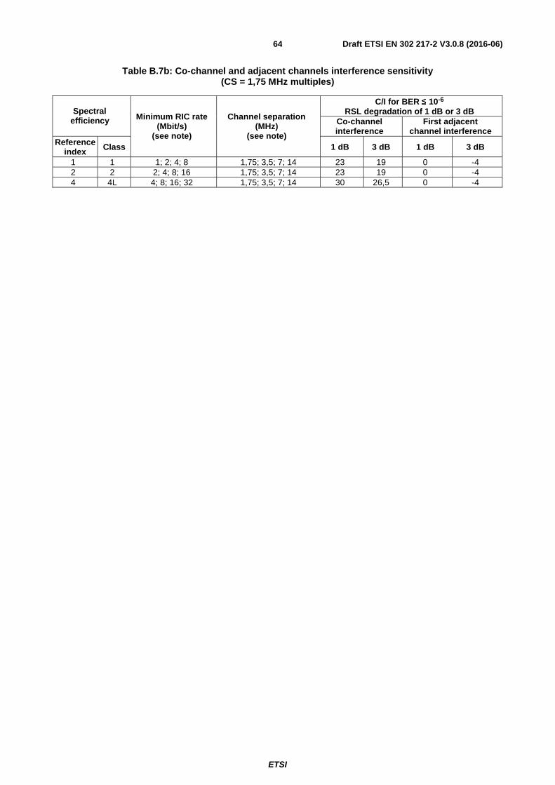
ETSI
Draft ETSI EN 302 217-2 V3.0.8 (2016-06)64
Table B.7b: Co-channel and adjacent channels interference sensitivity (CS = 1,75 MHz multiples)
Spectral efficiency Minimum RIC rate
(Mbit/s) (see note)
Channel separation (MHz)
(see note)
C/I for BER ≤ 10-6 RSL degradation of 1 dB or 3 dB
Co-channel interference
First adjacent channel interference
Reference index Class 1 dB 3 dB 1 dB 3 dB
1 1 1; 2; 4; 8 1,75; 3,5; 7; 14 23 19 0 -4 2 2 2; 4; 8; 16 1,75; 3,5; 7; 14 23 19 0 -4 4 4L 4; 8; 16; 32 1,75; 3,5; 7; 14 30 26,5 0 -4

ETSI
Draft ETSI EN 302 217-2 V3.0.8 (2016-06)65
Annex C (normative): Frequency bands from 3 GHz to 11 GHz (channel separation up to 30 MHz and 56/60 MHz)
C.1 Introduction This annex contains requirements for a variety of equipment that, depending on the channel arrangements adopted by the local administrations (according clause C.2.1 and table C.1), can offer various transmission capacities within given channel separations using the necessary spectral efficiency class (according clause C.2.2 and table C.2).
In this annex only FDD equipment are considered.
C.2 General characteristics
C.2.1 Frequency characteristics and channel arrangements In table C.1, ITU-R and ECC (formerly CEPT/ERC) recommended frequency channel arrangements, known at the date of publication of the present document, are specified for reference only. The channel arrangement is not relevant to article 3.2 requirements; only the frequency band and actual channel separation are relevant for defining the set of parameters and test suites relevant to each system mainly designed for that channel separation and that frequency band.
Other national or future ITU-R or CEPT/ECC recommendations set around the rough boundary of present ITU-R or CEPT/ECC recommendations are considered applicable to systems assessed against the present document, provided that they use the same channel separation.
For assessment of wide-band coverage systems see annex O.
Table C.1: Frequency characteristics
Band (GHz)
Frequency range (GHz)
Channel separation
(MHz)
Recommendations for radio frequency channel arrangements
ECC (CEPT/ERC) ITU-R
3,5 3,410 to 3,600 1,75 to 14 14-03 [i.15] -
4
3,600 to 3,800 1,75 to 14 12-08 annex B part 2 [i.10] - 3,600 to 4,200 30 12-08 annex A part 2 [i.10] F.635-6 [i.44] 3,600 to 4,200 60 (see note) - - 3,800 to 4,200 29 12-08 annex B part 1 [i.10] F.382-8 [i.36] 3,800 to 4,200 58 (see note) - -
U4 4,400 to 5,000 28 and 56 - F.1099-4 annex 3 [i.52]
60 - F.1099-4 annex 1 [i.52]
L6 5,925 to 6,425
29,65 and 59,3 14-01 [i.13] F.383-9 [i.37] 28 - F.383-9 annex 2 [i.37]
Guard and central gap 1,75 and 3,5 (14)06 [i.25] -
U6
Guard and central gap 1,75 and 3,5 (14)06 [i.25] - 6,425 to 7,100 20 14-02 [i.14] F.384-11 [i.38]
6,425 to 7,100 30 and 60 14-02 [i.14] F.384-11 [i.38] 3,5, 7, 14 14-02 annex 1 [i.14] F.384-11 annex 2 [i.38]
7
7,125 to 7,425
7 to 28 and 56
- F.385-10 [i.39] 7,425 to 7,725 - F.385-10 [i.39] 7,250 to 7,550 - F.385-10 [i.39] 7,550 to 7,850 - F.385-10 [i.39] 7,110 to 7,750 28 and 56 - F.385-10 annex 3 [i.39] 7,425 to 7,900 7 to 28 and 56 (02)06 annex 2.2 and annex 3 [i.22] F.385-10 annex 4 [i.39] 7,250 to 7,550 3,5 to 28 and 56 - F.385-10 annex 5 [i.39]
7,125 to 7,425 1,75 to 28 and 56
(02)06 annexes 1.1, 2.1 and annex 3 [i.22] F.385-10 annex 1 [i.39]
7,425 to 7,725 (02)06 annex 1.1 and annex 3 [i.22] F.385-10 annex 1 [i.39]

ETSI
Draft ETSI EN 302 217-2 V3.0.8 (2016-06)66
Band (GHz)
Frequency range (GHz)
Channel separation
(MHz)
Recommendations for radio frequency channel arrangements
ECC (CEPT/ERC) ITU-R
8
7,725 to 8,275 7, 14, 28 and 56 (02)06 annex 1.2.1 and annex 3 [i.22]] F.386-9 annex 2 [i.40] 29,65 and 59,3 (02)06 annex 1.2.2 and annex 3 [i.22] F.386-9 annex 6 [i.40]
7,725 to 8,275 30 and 60 - F.386-9 annex 1 [i.40] 8,025 to 8,500 7 to 28 and 56 - F.386-9 annex 5 [i.40] 8,275 to 8,500 7 to 28 and 56 (02)06 annex 1.3 and annex 3 [i.22] F.386-9 annex 2 [i.40] 7,900 to 8,400 7 to 28 and 56 - F.386-9 annex 3 [i.40] 7,900 to 8,500 1,75 to 28 and 56 (02)06 annex 2.3 and annex 3 [i.22] -
10,5
10,000 to 10,680 3,5 to 28 - F.747-1 annex 4 [i.48] 10,500 to 10,680 7 - F.747-1 annex 1 [i.48]
10,150 to 10,3 paired with 10,5 to 10,650 3,5 to 28 and 56 12-05 [i.7] F.747-1 annex 3 [i.48]
11 10,700 to 11,700 7, 14, 28 and 56 12-06 [i.8] F.387-12 annex 4 [i.41] NOTE: In bands from 3,6 GHz to 4,2 GHz, systems with 58/60 MHz CS do not rely on any Recommended CEPT or
ITU-R radio frequency channel arrangements providing channel separation up to 56 MHz to 60 MHz; however, in bands that provide 28 MHz to 30 MHz CS, it is assumed that aggregation of two half sized channels might be permitted on national basis. Also in higher bands the CEPT and Recommendations ITU-R provide the about 60 MHz CS only in term of aggregation of about 2 x 30 MHz CS, subject to their availability and possible national license restrictions.
C.2.2 Transmission capacities
Table C.2: Minimum RIC transmission capacity and system classes for various channel separation
Channel arrangement� Co-polar (ACCP)
Cross-polar (ACAP)
Channel separation (MHz) � 1,75 3,5 7 14 to 15 20 28 to 30 56 to 60 28 to 30 56 to 60
Min
. pay
load
RIC
rat
e M
bit
/s (
no
te 1
)
Spectral efficiency� � � � � � � � � � Reference
Index Class
2 2 2 4 8 16 - 32 64 - - 3 3 3 6 12 24 - 48 96 - - 4 4L 4 8 16 32 45 64 128 - - 5 4H - - 24 49 - 98 196 - -
6 5L - - 29 58 - - - - -
5LB, 5LA - - - - - 117 235 117 235
7 5H - - 34 68 - - - - -
5HB, 5HA - - - - - 137 274
(note 2) 137 274
(note 2)
8 6L - - 39 78 - - - - -
6LB, 6LA - - - - - 156 313 156 313
9 6H - - - 88 - - - - -
6HB, 6HA - - - - - 176 352 176 352
10 7 - - - 98 - - - - -
7B, 7A - - - - - 196 392 196 392
11 8 - - - 107 - - - - -
8B, 8A - - - - - 215 431 215 431 NOTE 1: For equipment assessment with different base band interfaces, see annex N. NOTE 2: Equipment requirements are set only on the basis of the RIC rate on one polarization. However, 4 × STM-1 or
STM-4 capacity can be possible by doubling 2 × STM-1 equipment either in CCDP operation or through operation of two 2 × STM-1 systems (or one channels-aggregation equipment) in two 55/56 MHz channels, which, due to spectrum availability, may also not be adjacent. For the assessment of such cases, refer to clause O.3. Similar considerations apply as well for Ethernet capacity, e.g. when 1000BaseT or N × 100BaseT capacity are concerned.

ETSI
Draft ETSI EN 302 217-2 V3.0.8 (2016-06)67
C.3 Transmitter
C.3.1 General requirements
Table C.3: Transmitter requirements
Requirements Limits Maximum transmitter power Clause 4.2.1.1 Nominal transmitter power tolerance Clause 4.2.1.3 Transmitter power and frequency control Clause 4.2.2 RF Spectrum power density mask Clause 4.2.3.2 Discrete CW components exceeding the spectrum mask limit Clause 4.2.4 Unwanted emissions in the spurious domain-external Clause 4.2.5 Dynamic Change of Modulation Order Clause 4.2.6 Radio frequency tolerance Clause 4.2.7
C.3.2 RF spectrum masks The masks in clause 4.2.3.2 are valid only for those specific combinations of CS, nominal capacity and spectral efficiency class that are also included among those foreseen in table C.2.
C.4 Receiver
C.4.1 General requirements
Table C.4: Receiver requirements
Requirements Limits Unwanted emissions in the spurious domain (External) Clause 4.3.1 BER as a function of RSL Table C.5 Co-channel external and adjacent channel interference sensitivity Table C.6 CW spurious interference Clause 4.3.3.4
C.4.2 BER as a function of Receiver input Signal Level (RSL) The supplier shall declare the RSL threshold(s) (dBm) for the relevant BER values (i.e. 10-6 and 10-8 or 10-10), which shall not be worse than the corresponding RSL upper bound values indicated in the table C.5. The declared Receiver Signal Levels (RSL) shall produce a BER ≤ 10-6 and either ≤ 10-8 or ≤ 10-10.
NOTE: RSL values, evaluated for typical implementation practice, may be found in ETSI TR 101 854 [i.31] and RSL for guaranteeing RBER performance may be found in ETSI EN 302 217-1 [4].
Table C.5: BER as a function of receiver input signal level RSL (upper bound)
Spectral efficiency Minimum RIC rate (Mbit/s)
Co-polar channel separation
(MHz)
RSL for BER ≤ 10-6
(dBm) (see note 2)
RSL for BER ≤ 10-8
(dBm) (see note 2)
RSL for BER ≤ 10-10
(dBm) (see note 2) Reference
index Class
2 2
2 1,75 -93 -91,5
-
4 3,5 -90 -88,5 8 7 -87 -85,5
16 14 to 15 -84 -82,5 32 28 to 30 -81 -79,5 64 56 to 60 -78 -76,5

ETSI
Draft ETSI EN 302 217-2 V3.0.8 (2016-06)68
Spectral efficiency Minimum RIC rate (Mbit/s)
Co-polar channel separation
(MHz)
RSL for BER ≤ 10-6
(dBm) (see note 2)
RSL for BER ≤ 10-8
(dBm) (see note 2)
RSL for BER ≤ 10-10
(dBm) (see note 2) Reference
index Class
3 3
3 1,75 -88 -86,5
-
6 3,5 -85 -83,5 12 7 -82 -80,5 24 14 to 15 -79 -77,5 48 28 to 30 -76 -74,5 96 56 to 60 -73 -71,5
4 4L
4 1,75 -86 -84,5
-
8 3,5 -83 -81,5 16 7 -80 -78,5 32 14 to 15 -77 -75,5 45 20 -76 -74,5 64 28 to 30 -74 -72,5
128 56 to 60 -71 - -68
5 4H
24 7 -77 -75,5 - 49 14 to 15 -74 -72,5 - 98 28 to 30 -71 -69,5 -
196 56 to 60 -68 - -65
6
5L 29 7 -74 -72,5 - 58 14 to 15 -71 -69,5 -
5LA/5LB
(note 1)
117 28 to 30 (ACAP/ACCP) -68 - -65
235 56 to 60
(ACAP/ACCP) -65 - -62
7
5H 34 7 -72,5 -71 - 68 14 to 15 -69,5 -68 -
5HA/5HB
(note 1)
137 28 to 30 (ACAP/ACCP) -67 - -64
274 56 to 60 (ACAP/ACCP) -64 - -61
8
6L 39 7 -68 -66,5 - 78 14 to 15 -65 -63,5 -
6LA/6LB (note
1)
156 28 to 30 (ACAP/ACCP) -63 - -60
313 56 to 60 (ACAP/ACCP) -60 - -57
9
6H 88 14 to 15 -61 -59,5
6HA/6HB
(note 1)
176 28 to 30 (ACAP/ACCP) -58,5 - -55,5
352 56 to 60
(ACAP/ACCP) -56 - -53
10
7 98 14 to 15 -57,5 -56 -
7A/7B (note 1)
196 28 to 30 (ACAP/ACCP) -55 - -52
392 56 to 60 (ACAP/ACCP) -52,5 - -49,5
11
8 107 14 to 15 -54,5 - -51,5
8A/8B (note 1)
215 28 to 30 (ACAP/ACCP) -51,5 - -48,5
431 56 to 60 (ACAP/ACCP) -49 - -46
NOTE 1: For CS 28 MHz to 30 MHz or 56 MHz to 60 MHz, systems of classes 5LB, 5HB, 6LB, 6HB, 7B and 8B, the limits are required when the connection to the same antenna port of even and odd channels, spaced about 30 MHz or about 60 MHz, respectively, apart on the same polarization, is made with the use of an external 3 dB hybrid coupler placed at reference point C. When alternatively, for the above purpose, narrow-band branching filters solution are used, the above BER performance thresholds may be relaxed by 1,5 dB.
NOTE 2: For channels-aggregation/single-port equipment, in the event that the device combining the two received signals is integrated in the equipment, the RSL thresholds will be relaxed by the combining device loss (e.g. 3 dB for a hybrid coupler).

ETSI
Draft ETSI EN 302 217-2 V3.0.8 (2016-06)69
C.4.3 Co-channel "external" and adjacent channel interference sensitivity
The limits of Carrier to Interference ratio (C/I) in case of co-channel and first adjacent channel interference shall be as set out in table C.6, giving maximum C/I values for 1 dB and 3 dB degradation of the RSL limits declared for BER ≤ 10-6 in clause C.4.2.
NOTE: For the purpose of frequency co-ordination, intermediate co-channel or adjacent channel sensitivity values may be found in annex Q.
Table C.6: Co-channel and adjacent channel interference sensitivity
Spectral efficiency Minimum RIC rate
(Mbit/s) (see note)
Channel separation (MHz)
(see note)
C/I for BER ≤ 10-6 RSL degradation of 1 dB or 3 dB
Co-channel interference
First adjacent channel interference
Reference index Class 1 dB 3 dB 1 dB 3 dB
2 2 2; 4; 8; 16; 32; 64 1,75; 3,5; 7; 14 to 15; 28 to 30; 56 to 60
23 19 0 -4
3 3 3; 6; 12; 24; 48; 96 1,75; 3,5; 7; 14 to 15; 28 to 30; 56 to 60 27 23 -1 -5
4 4L 4; 8; 16; 32; 64; 128 1,75; 3,5; 7; 14 to 15;
28 to 30; 56 to 60 30 26,5 -3 -7
45 20 30 26,5 -8 -12
5 4H 24; 49; 98; 196 7; 14 to 15; 28 to 30; 56 to 60 33 29 -5 -9
6 5L 29; 58 7; 14 to 15
34 30 -3 -7 5LB 117; 235 28 to 30; 56 to 60 (ACCP) 5LA 117; 235 28 to 30; 56 to 60 (ACAP) 34 30 4 1
7 5H 34; 64 7; 14 to 15 37 33 -2 -6
5HB 137 28 to 30; 56 to 60 (ACCP) 35 32 -5 -8 5HA 137; 274 28 to 30; 56 to 60 (ACAP) 37 33 3 -1
8 6L
39 7 40 36 0 -4
78 14 to 15 6LB 156; 313 28 to 30; 56 to 60 (ACCP) 40 36 0 -4 6LA 156; 313 28 to 30; 56 to 60 (ACAP) 40 36 10 7
9 6H 88 14 to 15
43 39 0 -4 6HB 176; 352 28 to 30; 56 to 60(ACCP) 6HA 176; 352 28 to 30; 56 to 60 (ACAP) 43 39 10 6
10 7 98 14 to 15
46 42 0 -4 7B 196; 392 28 to 30; 56 to 60 (ACCP) 7A 196; 392 28 to 30; 56 to 60 (ACAP) 46 42 13 9
11 8 107 14 to 15
50 46 0 -4 8B 215; 431 28 to 30; 56 to 60 (ACCP) 8A 215; 431 28 to 30; 56 to 60 (ACAP) 50 46 17 13
NOTE: Minimum RIC and Channel separation series of values in each row are intended one to one coupled in their orders.

ETSI
Draft ETSI EN 302 217-2 V3.0.8 (2016-06)70
Annex D (normative): Frequency bands from 3 GHz to 11 GHz (channel separation 40 MHz)
D.1 Introduction This annex contains requirements for equipment that, depending on the 40 MHz channel arrangements adopted by the local administrations (according clause D.2.1 and table D.1), can offer different transmission capacities using the necessary spectral efficiency class (according clause D.2.2 and table D.2).
In this annex only FDD equipment are considered.
D.2 General characteristics
D.2.1 Frequency characteristics and channel arrangements In table D.1, ITU-R and ECC (formerly CEPT/ERC) recommended frequency channel arrangements, known at the date of publication of the present document, are specified for reference only. The channel arrangement is not relevant to article 3.2 requirements; only the frequency band and actual channel separation is relevant for defining the set of parameters and test suites relevant to each system designed for that channel separation.
Other national or future ITU-R or CEPT/ECC recommendations set around the rough boundary of present ITU-R or CEPT/ECC Recommendations are considered applicable to systems assessed against the present document, provided that they use the same channel separation.
For assessment of wide-band coverage systems see annex O.
Table D.1: Frequency characteristics
Band (GHz)
Frequency range (GHz)
Recommendations for radio frequency channel arrangements CEPT/ECC ITU-R
4 3,600 to 4,200 12-08 annex A part 1 [i.10] F.635-6 [i.44] U4 4,400 to 5,000 - F.1099-4 annex 1 and annex 2 [i.52] U6 6,425 to 7,110 14-02 [i.14] F.384-11 [i.38] 8 7,725 to 8,275 - F.386-9 annex 4 [i.40]
11 10,7 to 11,7 12-06 [i.8] F.387-12 [i.41]
D.2.2 Transmission capacities NOTE: The use in CEPT countries of 40 MHz CS in the bands subject of this annex is generally limited to "high
capacity" links. For this reason system with efficiency classes lower than 5L are not provided in the present document. Nevertheless, if lower classes are desired for some special cases, informative reference characteristics (not useable for Directive 2014/53/EU [i.1] self-declaration of conformance) may be derived from the corresponding classes and bands within 28 MHz CS in annex C as follows: # spectrum masks: frequency corners multiplied by 40/28 # minimum RIC: multiplied by 40/28 # RSL thresholds: increased by 10 log (40/28) # Co-channel behaviour: same # 40 MHz adjacent channel behaviour: same of that at 28 MHz.

ETSI
Draft ETSI EN 302 217-2 V3.0.8 (2016-06)71
Table D.2: Minimum RIC transmission capacity and system classes for various channel separation
D.3 Transmitter
D.3.1 General requirements
Table D.3: Transmitter requirements
Requirements Limits Maximum transmitter power Clause 4.2.1.1 Nominal transmitter power tolerance Clause 4.2.1.3 Transmitter power and frequency control Clause 4.2.2 RF Spectrum power density mask Clause 4.2.3.2 Discrete CW components exceeding the spectrum mask limit Clause 4.2.4 Unwanted emissions in the spurious domain -external Clause 4.2.5 Dynamic Change of Modulation Order Clause 4.2.6 Radio frequency tolerance Clause 4.2.7
D.3.2 RF spectrum masks The masks in clause 4.2.3.2 are valid only for those specific combinations of CS, nominal capacity and spectral efficiency class that are also included among those foreseen in table D.2. Class 5HB/28 systems shall refer to the corresponding 28 MHz mask.
Channel arrangement � Co-polar (ACCP) Cross-polar (ACAP) Channel separation� 40 MHz 40 MHz
Min
. pay
load
RIC
rat
e M
bit
/s (
no
te 1
) Spectral efficiency � � � Reference index Class
6 5LB STM-1 or 137 - 5LB 168 - 5LA - 168
7 5HB/28 (note 2) STM-1 or 137 -
5HB 196 - 5HA - 196
8 6LA - 224 6LB 224 -
9 6HA (note 3) - 252 6HB (note 3) 252 -
10 7A (note 3) - 280 7B (note 3) 280 -
11 8A - 308 8B 308 -
NOTE 1: For equipment assessment with different base band interfaces see annex N. NOTE 2: This case provides system parameters, intended for ACCP or CCDP operation with a minimum RIC that does
not fulfil the minimum RIC density established in clause 1.2. This is intended for commonality in order to cover also the 40 MHz channel arrangements with STM-1 systems used in the more popular 28 MHz arrangements.
NOTE 3: Equipment requirements are set only on the basis of the RIC rate on one polarization per 40 MHz channel. However, 4 × STM-1 or STM-4 capacity can be possible by doubling 2 × STM-1 equipment either in CCDP operation or through operation of two 2 × STM-1 systems (or one channels-aggregation equipment) in two 40 MHz channels, which, due to spectrum availability, may also not be adjacent. For the assessment of such cases, refer to clause O.3. Similar considerations apply as well for Ethernet capacity, e.g. when 1000BaseT or N × 100BaseT capacity are concerned.

ETSI
Draft ETSI EN 302 217-2 V3.0.8 (2016-06)72
D.4 Receiver
D.4.1 General requirements
Table D.4: Receiver requirements
Requirements Limits Unwanted emissions in the spurious domain (external) Clause 4.3.1 BER as a function of RSL Table D.5 Co channel external and adjacent channel interference sensitivity Table D.6 CW spurious interference Clause 4.3.3.4
D.4.2 BER as a function of Receiver input Signal Level (RSL) The supplier shall declare the RSL threshold(s) (dBm) for the relevant BER values (i.e. 10-6 and 10-10), which shall not be worse than the corresponding RSL upper bound values indicated in table D.5. The declared Receiver Signal levels shall produce a BER of either ≤ 10-6 or ≤ 10-10.
NOTE: RSL values, evaluated for typical implementation practice, may be found in ETSI TR 101 854 [i.31] and RSL for guaranteeing RBER performance may be found in ETSI EN 302 217-1 [4].
Table D.5: BER as a function of receiver input signal level RSL (upper bound)
Spectral efficiency Minimum RIC rate (Mbit/s)
Channel separation
(MHz)
Frequency band(s) (GHz)
RSL for BER ≤ 10-6
(dBm)
RSL for BER ≤ 10-10
(dBm) Reference
index Class
6 5LB STM-1 or 137
40 ACCP
4, U4, U6, 8 -69 -66 11 -68 -65
5LA/5LB 168 4, U4, U6, 8 -68 -65
11 -67 -64
7 5HA/5HB 196 40 ACCP
4, U4, U6, 8 -63,5 -60,5 11 -63,5 -60,5
5HB/28 STM-1 or 137 40 ACCP 4, U4, U6, 8 -65 -62
11 -64 -61 8 6LA/6LB 224 40 ACAP/ACCP 4, U4, U6, 8, 11 -60,5 -57,5 9 6HA/6HB 252 40 ACAP/ACCP 4, U4, U6, 8, 11 -57,5 -54,5 10 7A/7B 280 40 ACAP/ACCP 4, U4, U6, 8, 11 -54 -51 11 8A/8B 308 40 ACAP/ACCP 4, U4, U6, 8, 11 -50,5 -47,5
NOTE 1: These limits are required when the connection to the same antenna port of even and odd channels, spaced 40 MHz apart on the same polarization, is made with the use of an external 3 dB hybrid coupler placed at reference point C. When alternatively, for the above purpose, narrow-band branching filters solutions are used, the above BER performance thresholds may be relaxed by 1,5 dB.
NOTE 2: For channels-aggregation/single-port equipment, in the event that the device combining the two received signals is integrated in the equipment, the RSL thresholds will be relaxed by the combining device loss (e.g. 3 dB for a hybrid coupler).

ETSI
Draft ETSI EN 302 217-2 V3.0.8 (2016-06)73
D.4.3 Co-channel "external" and adjacent channel interference sensitivity
The limits of Carrier to Interference ratio (C/I) in case of co-channel and adjacent channel interference shall be as in table D.6, giving maximum C/I values for 1 dB and 3 dB degradation of the RSL limits declared for BER ≤ 10-6 in clause D.4.2.
Table D.6: Co-channel and adjacent channel interference sensitivity
Spectral efficiency Minimum RIC rate (Mbit/s)
Channel separation
(MHz)
C/I for BER ≤ 10-6 RSL degradation of 1 dB or 3 dB
Co-channel interference
First adjacent channel interference
Reference index Class 1 dB 3 dB 1 dB 3 dB
6 5LA 168 40 (ACAP) 33 29 3 0
5LB STM-1 or 137
40 (ACCP) 33 29 -4 -8
168 33 29 -3 -7
7 5HA 196 40 (ACCP) 37 33 7 4
5HB/28 STM-1 or 137 40 (ACCP) 37 33 -4 -8 5HB 196 40 (ACCP) 37 33 -3 -7
8 6LA 224 40 (ACAP) 40 36 10 7 6LB 224 40 (ACCP) 40 36 0 -4
9 6HA 252 40 (ACAP) 43 39 10 7 6HB 252 40 (ACCP) 43 39 0 -4
10 7A 280 40 (ACAP) 46 42 13 9 7B 280 40 (ACCP) 46 42 0 -4
11 8A 308 40 (ACAP) 50 46 17 13 8B 308 40 (ACCP) 50 46 0 -4

ETSI
Draft ETSI EN 302 217-2 V3.0.8 (2016-06)74
Annex E (normative): Frequency bands 13 GHz, 15 GHz and 18 GHz
E.1 Introduction This annex contains requirements for a variety of equipment that, depending on the channel arrangements adopted by the local administrations (according clause E.2.1 and table E.1), can offer various transmission capacities within given channel separations using the necessary spectral efficiency class (according clause E.2.2 and table E.2).
In this annex only FDD equipment are considered.
E.2 General characteristics
E.2.1 Frequency characteristics and channel arrangements In table E.1, ITU-R and ECC (formerly CEPT/ERC) recommended frequency channel arrangements, known at the date of publication of the present document, are specified for reference only. The channel arrangement is not relevant to article 3.2 requirements; only the frequency band and actual channel separation are relevant for defining the set of parameters and test suites relevant to each system designed for that channel separation.
Other national or future ITU-R or CEPT/ECC recommendations set around the rough boundary of present ITU-R or CEPT/ECC recommendations are considered applicable to systems assessed against the present document, provided that they use the same channel separation.
For assessment of wide-band coverage systems, see annex O.
Table E.1: Frequency characteristics
Band (GHz)
Frequency range (GHz)
Channel separation (MHz)
Recommendations for radio frequency channel arrangements
ECC (CEPT/ERC) ITU-R 13 12,75 to 13,25 1,75 to 28 12-02 [i.5] F.497-7 [i.42] 13 12,75 to 13,25 56 (note 3) 12-02 [i.5] F.497-7 [i.42]
15 14,5 to14,62 paired with 15,23 to15,35
1,75 to 56 12-07 [i.9]
F.636-4 [i.45] 14,5 to 15,35 -
18 17,7 to 19,7 13,75 to 110
or 1,75 to 14 (note 2)
12-03 [i.6] (note 1)
F.595-10 [i.43] (note 1)
NOTE 1: CEPT Recommendation 12-03 [i.6] allows for low-capacity channel arrangements on a national basis. Recommendation ITU-R F.595-10 [i.43] details various channel arrangements including low-capacity channel arrangements.
NOTE 2: As recommended CEPT channel separation lower than 13,75 MHz are not available in the 18 GHz frequency band at the date of the present document, the equipment requirements set for system in 18 GHz band for CS 1,75 MHz to 14 MHz are considered for the use in national frequency plans based on 1,75/3,5/7/14 MHz basic pattern.
NOTE 3: In the 13 GHz band the CEPT and Recommendations ITU-R provide the 56 MHz CS only in term of aggregation of 2 × 28 MHz CS, subject to their availability and possible national license restrictions.

ETSI
Draft ETSI EN 302 217-2 V3.0.8 (2016-06)75
E.2.2 Transmission capacities
Table E.2: Minimum RIC transmission capacity and system classes for various channel separation
Channel arrangement �
Co-polar (ACCP) Cross-polar (ACAP)
Channel separation (MHz) �
1,75
3,5 7
13,7
5/14
27,5
/28
55/5
6
110
(18
GH
z)
27,5
/28
55/5
6
110
(18
GH
z)
Min
. pay
load
RIC
rat
e M
bit
/s (
no
te 1
)
Spectral Efficiency ↓ Reference
index Class
2 2 2 4 8 16 32 64 128 - - - 3 3 3 6 12 24 48 96 191 - - - 4 4L 4 8 16 32 64 128 256 - - - 5 4H - 12 24 49 98 196 392 - - -
6 5L - - 29 58 - - - - - -
5LB, 5LA - - - - 117 235 470 117 235 470
7 5H - 17 34 68 - - - - - -
5HB, 5HA - - - - 137 (note 2)
274 (note 2)
548 137 (note 2)
274 (note 2)
548
8 6L - - 39 78 - - - - - -
6LB, 6LA - - - - 156
(note 2) 313
(note 2) 627 156
(note 2) 314
(note 2) 627
9 6H - - - 88 - - - - - -
6HB, 6HA - - - - 176 352 705 176 352 705
10 7 - - - 98 - - - - - -
7B, 7A - - - - 196 392 784 196 392 784
11 8 - - - 107 - - - - - -
8B, 8A - - - - 215 431 862 215 431 862 NOTE 1: For equipment assessment with different base band interfaces see annex N. NOTE 2: Equipment requirements are set only on the basis of the RIC rate on one polarization. However, 4 × STM-1 or
STM-4 capacity can be possible by doubling 2 × STM-1 equipment either in CCDP operation or through operation of two 2 × STM-1 systems (or one channels-aggregation equipment) in two separate 55/56 MHz channels, which, due to spectrum availability, may also not be adjacent. For the assessment of such cases, refer to clause O.3. Similar considerations apply as well for Ethernet capacity, e.g. when 1000BaseT or N × 100BaseT capacity are concerned.
E.3 Transmitter
E.3.1 General requirements
Table E.3: Transmitter requirements
Requirements Limits
Maximum transmitter power Clause 4.2.1.1 Nominal transmitter power tolerance Clause 4.2.1.3 Transmitter power and frequency control Clause 4.2.2 RF spectrum power density mask Clause 4.2.3.2 Discrete CW components exceeding the spectrum mask limit Clause 4.2.4 Unwanted emissions in the spurious domain - external Clause 4.2.5 Dynamic Change of Modulation Order Clause 4.2.6 Radio frequency tolerance Clause 4.2.7
E.3.2 RF spectrum masks The masks in clause 4.2.3.2 are valid only for those specific combinations of CS, nominal capacity and spectral efficiency class that are also included among those foreseen in table E.2.

ETSI
Draft ETSI EN 302 217-2 V3.0.8 (2016-06)76
E.4 Receiver
E.4.1 General requirements
Table E.4: Receiver requirements
Requirements Limits Unwanted emissions in the spurious domain (External) Clause 4.3.1
BER as a function of RSL Table E.5a (equipment operating in 13 GHz and 15 GHz bands) Table E.5b (equipment operating in 18 GHz band)
Co channel external and adjacent channel interference sensitivity Table E.6
CW spurious interference Clause 4.3.3.4
E.4.2 BER as a function of Receiver input Signal Level (RSL) The supplier shall declare the RSL threshold(s) (dBm) for the relevant BER values (i.e. 10-6 and 10-8 or 10-10), which shall not be worse than the corresponding RSL upper bound values indicated in tables E.5a and E.5b. The declared Receiver Signal levels shall produce a BER of 10-6 or either ≤ 10-8 or ≤ 10-10.
NOTE: RSL values, evaluated for typical implementation practice, may be found in ETSI TR 101 854 [i.31] and RSL for guaranteeing RBER performance may be found in ETSI EN 302 217-1 [4].
Table E.5a: BER as a function of receiver input signal level RSL (upper bound) for 13 GHz and 15 GHz bands
Spectral efficiency Minimum RIC rate
(Mbit/s) Channel separation
(MHz)
RSL for BER ≤ 10-6
(dBm)
RSL for BER ≤ 10-8
(dBm)
RSL for BER ≤ 10-10
(dBm) Reference
index Class
2 2
2 1,75 -93 -91,5 - 4 3,5 -90 -88,5 - 8 7 -87 -85,5 -
16 14 -84 -82,5 - 32 28 -81 -79,5 - 64 56 -78 -76,5 -
3 3
3 1,75 -88 -86,5 - 6 3,5 -85 -83,5 - 12 7 -82 -80,5 - 24 14 -79 -77,5 - 48 28 -76 -74,5 - 96 56 -73 -71,5 -
4 4L
4 1,75 -86 -84,5 - 8 3,5 -83 -81,5 - 16 7 -80 -78,5 - 32 14 -77 -75,5 - 64 28 -74 -72,5 -
128 56 -71 - -68
5 4H
24 7 -77 -75,5 - 49 14 -74 -72,5 - 98 28 -71 -69,5 -
196 56 -68 - -65
6
5L 29 7 -74 -72,5 - 58 14 -71 -69,5 -
5LA/5LB (note)
117 28 (ACAP/ACCP) -68 - -65
235 56 (ACAP/ACCP) -65 - -62
7 5H
34 7 -71,5 -70 - 68 14 -68,5 -67 -
5HA/5HB (note)
137 28 (ACAP/ACCP) -65,5 - -62,5 274 56 (ACAP/ACCP) -62 - -59

ETSI
Draft ETSI EN 302 217-2 V3.0.8 (2016-06)77
Spectral efficiency Minimum RIC rate
(Mbit/s) Channel separation
(MHz)
RSL for BER ≤ 10-6
(dBm)
RSL for BER ≤ 10-8
(dBm)
RSL for BER ≤ 10-10
(dBm) Reference
index Class
8 6L
39 7 -67,5 -66 - 78 14 -64,5 -63 -
6LA/6LB (note)
156 28 (ACAP/ACCP) -62 - -59 313 56 (ACAP/ACCP) -59 - -56
9 6H 88 14 -61 -59,5 -
6HA/6HB (note)
176 28 (ACAP/ACCP) -58,5 - -55,5 352 56 (ACAP/ACCP) -56 - -53
10 7 98 14 -57,5 -56 -
7A/7B (note)
196 28 (ACAP/ACCP) -55 - -52 392 56 (ACAP/ACCP) -52,5 - -49,5
11 8 107 14 -54,5 - -51,5
8A/8B (note)
215 28 (ACAP/ACCP) -51,5 - -48,5 431 56 (ACAP/ACCP) -49 - -46
NOTE: For channels-aggregation/single-port equipment, in the event that the device combining the two received signals is integrated in the equipment, the RSL thresholds will be relaxed by the combining device loss (e.g. 3 dB for a hybrid coupler).
Table E.5b: BER as a function of receiver input signal level RSL (upper bound) for 18 GHz bands
Spectral efficiency Minimum RIC rate (Mbit/s)
Channel separation (MHz)
RSL for BER ≤ 10-6
(dBm)
RSL for BER ≤ 10-8
(dBm)
RSL for BER ≤ 10-10
(dBm) Reference
index Class
2 2
2 1,75 -92 -90,5 - 4 3,5 -89 -87,5 - 8 7 -86 -84,5 -
16 14/13,75 -83 -81,5 - 32 27,5 -80 -78,5 - 64 55 -77 -75,5 -
128 110 -74 - -71
3 3
3 1,75 -87 -85,5 - 6 3,5 -84 -82,5 -
12 7 -81 -79,5 - 24 14/13,75 -78 -76,5 - 48 27,5 -75 -73,5 - 96 55 -72 -70,5 -
191 110 -69 - -66
4 4L
4 1,75 -85 -83,5 - 8 3,5 -82 -80,5 -
16 7 -79 -77,5 - 32 14/13,75 -76 -74,5 - 64 27,5 -73 -71,5 -
128 55 -70 - -67 256 110 -67 - -64
5 4H
12 3,5 -79 -77,5 - 24 7 -76 -74,5 - 49 14/13,75 -73 -71,5 - 98 27,5 -70 -68,5 -
196 55 -67 - -64 392 110 -64 - -61
6
5L 29 7 -73 -71,5 - 58 14/13,75 -70 -68,5 -
5LA/5LB (note 1)
117 27,5 -67 - -64 235 55 -64 - -61 470 110 -61 - -58

ETSI
Draft ETSI EN 302 217-2 V3.0.8 (2016-06)78
Spectral efficiency Minimum RIC rate (Mbit/s)
Channel separation (MHz)
RSL for BER ≤ 10-6
(dBm)
RSL for BER ≤ 10-8
(dBm)
RSL for BER ≤ 10-10
(dBm) Reference
index Class
7
5H 17 3,5 -73 -71,5 - 34 7 -70 -68,5 - 68 13,75 -67 -65,5 -
5HA/5HB (note 1)
137 27,5 (ACAP/ACCP) -64 - -61 274 55 (ACAP/ACCP) -61 - -58 548 110 (ACAP/ACCP) -58 - -55
8
6L 39 7 -66 -64,5 - 78 13,75/14 -63,5 -62 -
6LA/6LB (note 1)
156 27,5 (ACAP/ACCP) -61 - -58 313 55 (ACAP/ACCP) -58 - -55 627 110 (ACAP/ACCP) -55 - -52
9
6H 88 13,75/14 -60 -58,5 -
6HA/6HB (note 1)
176 27,5 (ACAP/ACCP) -57,5 - -54,5 352 55 (ACAP/ACCP) -55 - -52 705 110 (ACAP/ACCP) -52 - -49
10
7 98 13,75/14 -56,5 -55 -
7A/7B (note 1)
196 27,5 (ACAP/ACCP) -54 - -51 392 55 (ACAP/ACCP) -51,5 - -48,5 784 110 (ACAP/ACCP) -49 - -46
11
8 107 13,75/14 -53,5 - -50,5
8A/8B (note 1)
215 27,5 (ACAP/ACCP) -50,5 - -47,5 431 55 (ACAP/ACCP) -48 - -45 862 110 (ACAP/ACCP) -45,5 - -42,5
NOTE 1: For CS 27,5 MHz or 55 MHz or 110 MHz, systems of classes 5HB, 6LB and 7B, the limits are required when the connection to the same antenna port of even and odd channels, spaced 27,5 MHz or 55 MHz, or 110 MHz, respectively, apart on the same polarization, is made with the use of an external 3 dB hybrid coupler placed at reference point C. When alternatively, for the above purpose, narrow-band branching filters solution are used, the above BER performance thresholds may be relaxed by 1,5 dB.
NOTE 2: For channels-aggregation/single-port equipment, in the event that the device combining the two received signals is integrated in the equipment, the RSL thresholds will be relaxed by the combining device loss (e.g. 3 dB for a hybrid coupler).
E.4.3 Co-channel "external" and adjacent channel interference sensitivity
The limits of Carrier to Interference ratio (C/I) in case of co-channel and adjacent channel interference shall be as in table E.6, giving maximum C/I values for 1 dB and 3 dB degradation of the RSL limits declared for BER ≤ 10-6 in clause E.4.2.
Table E.6: Co-channel and adjacent channel interference sensitivity
Spectral efficiency Minimum RIC rate
(Mbit/s) (see note)
Channel separation (MHz)
(see note)
C/I for BER ≤ 10-6 RSL degradation of 1 dB or 3 dB
Reference index Class
Co-channel interference
adjacent channel interference
1 dB 3 dB 1 dB 3 dB
2 2 2; 4; 8; 16; 32; 64 1,75; 3,5; 7; 14; 28; 56 23 19 0 -4
16; 32; 64; 128 13,75; 27,5; 55; 110 23 19 1 -3
3 3 3; 6; 12; 24; 48 1,75; 3,5; 7; 14; 28; 56 27 24,5 -1 -5 24; 48; 96; 191 13,75; 27,5; 55; 110 27 24,5 -0 -4
4 4L 4; 8; 16; 32; 64 1,75; 3,5; 7; 14; 28 30 26,5 -1 -5
32; 64 13,75; 27,5 30 26,5 0 -4 128; 256 55/56; 110 29 25 -5 -9
5 4H 12 3,5 30 26 -4 -8
24; 49; 98; 196 7; 14; 28; 56 30 26,5 -6 -9,5 49; 98; 196; 392 13,75; 27,5; 55; 110 30 26,5 -2 -5,5
6 5L 29; 58 7; 13,75/14 34 30 -3 -7
5LB 117; 235; 470 27,5/28; 55/56; 110 (ACCP) 34 30 -3 -7

ETSI
Draft ETSI EN 302 217-2 V3.0.8 (2016-06)79
Spectral efficiency Minimum RIC rate
(Mbit/s) (see note)
Channel separation (MHz)
(see note)
C/I for BER ≤ 10-6 RSL degradation of 1 dB or 3 dB
Reference index Class
Co-channel interference
adjacent channel interference
1 dB 3 dB 1 dB 3 dB 5LA 117; 235; 470 27,5/28; 55/56; 110 (ACAP) 34 30 4 1
7
5H 17 3,5 37 33 0 -4
34; 68 7; 13,75/14 37 33 -3,5 -7,5
5HB 137
28 35 32 -5 -8 27,5 37 33 -3 -7
274 55/56 37 33 -3,5 -7,5 548 110 37 33 -3,5 -7,5
5HA 137; 274; 548 27,5/28; 55/56; 110 (ACAP) 37 33 3 -1
8 6L 39; 78 7; 13,75/14 40 36 0 -4
6LB 156; 313; 627 27,5/28; 55/56; 110 (ACCP) 40 36 0 -4 6LA 156; 313; 627 27,5/28; 55/56; 110 (ACAP) 40 36 10 7
9 6H 88 13,75/14
43 39 0 -4 6HB 176; 352; 705 27,5/28; 55/56; 110 (ACCP) 6HA 176; 352; 705 27,5/28; 55/56; 110 (ACAP) 43 39 10 6
10 7 98 13,75/14 46 42 0 -4
7B 196; 392; 784 27,5/28; 55/56; 110 (ACCP) 46 42 0 -4 7A 196; 392; 784 27,5/28; 55/56; 110 (ACAP) 46 42 13 9
11 8 107 13,75/14
50 46 0 -4 8B 215; 431; 862 27,5/28; 55/56; 110 (ACCP) 8A 215; 431; 862 27,5/28; 55/56; 110 (ACAP) 50 46 17 13
NOTE: Minimum RIC and Channel separation series of values in each row are intended one to one coupled in their orders.

ETSI
Draft ETSI EN 302 217-2 V3.0.8 (2016-06)80
Annex F (normative): Frequency bands from 23 GHz to 42 GHz
F.1 Introduction This annex contains requirements for a variety of equipment that, depending on the channel arrangements adopted by the local administrations (according clause F.2.1 and table F.1), can offer various transmission capacities within given channel separations using the necessary spectral efficiency class (according clause F.2.2 and table F.2).
In this annex only FDD equipment is considered except for the 31 GHz (31,0 GHz to 31,3 GHz) band where both FDD and TDD are considered.
F.2 General characteristics
F.2.1 Frequency characteristics and channel arrangements In table F.1, ITU-R and ECC (formerly CEPT/ERC) recommended frequency channel arrangements, known at the date of publication of the present document, are specified for reference only. The channel arrangement is not relevant to article 3.2 requirements; only the frequency band and actual channel separation are relevant for defining the set of parameters and test suites relevant to each system designed for that channel separation.
Other national or future ITU-R or CEPT/ECC recommendations set around the rough boundary of present ITU-R or CEPT/ECC recommendations are considered applicable to systems assessed against the present document, provided that they use the same channel separation.
For assessment of wide-band coverage systems see annex O.
Table F.1: Frequency characteristics
Band (GHz)
Frequency range (GHz)
Channel separation (MHz)
Recommendations for radio frequency channel arrangements ECC (CEPT/ERC) ITU-R
23 22,0 to 23,6 3,5 to 112 T/R 13-02 annex A [i.18] F.637-4 [i.46] 26 24,5 to 26,5 3,5 to 112 T/R 13-02 annex B [i.18] F.748-4 [i.49] 28 27,5 to 29,5 3,5 to 112 T/R 13-02 annex C [i.18] F.748-4 [i.49]
31 31,0 to 31,3 3,5 to 28/56 (see note 1) 02-02 [i.20] F.746-10 annex 7 [i.47]
32 31,8 to 33,4 3,5 to 112 01-02 [i.4] F.1520-3 [i.59] 38 37,0 to 39,5 3,5 to 112 T/R 12-01 [i.16] F.749-3 [i.50] 42 40,5 to 43,5 7 to 112 (see note 2) 01-04 [i.19] F.2005 [i.60]
NOTE 1: In 31 GHz band, no recommended CEPT or ITU-R radio frequency channel arrangements providing for channel separation of 56 MHz; however, it is assumed that aggregation of two half sized channels might be permitted on national basis.
NOTE 2: 2014 revision of ECC/REC(01)04 [i.19] has extended the maximum channel size to 224 MHz. However, the present document has not yet included that channel size.

ETSI
Draft ETSI EN 302 217-2 V3.0.8 (2016-06)81
F.2.2 Transmission capacities
Table F.2: Minimum RIC transmission capacity and system classes for various channel separation
Channel arrangement � Co-polar (ACCP) Cross-polar (ACAP) Channel separation (MHz) � 3,5 7 14 28 56 112 28 56 112
Min
imu
m p
aylo
ad R
IC r
ate
Mb
it/s
(n
ote
1)
Spectral efficiency � Frequency
band (GHz) �
� �
� �
� �
� �
� �
� �
� �
� �
� � Reference
index Class
2 2 23 to 38 4 8 16 32 64 128 - - -
42 - 8 16 32 64 128 - - -
3 3 23 to 38 6 12 24 48 96 191 - - -
42 - 12 24 48 96 191 - - -
4 4L 23 to 38 8 16 32 64 128 256 - - -
42 - 16 32 64 128 256 - - - 5 4H 23 to 42 - 24 49 98 196 392 - - -
6 5L 23 to 42 - 29 58 - - - - - -
5LB, 5LA 23 to 42 - - - 117 235 470 117 235 470
7 5H 23 to 42 - 34 68 - - - - - -
5HB, 5HA 23 to 42 - - - 137 (note 2)
274 (note 2) 548 137
(note 2) 274
(note 2) 548
8 6L 23 to 42 - 39 78 - - - - - -
6LB, 6LA 23 to 42 - - - 156 313 627 156 313 627
9 6H 23 to 42 - - 88 - - - - - -
6HB, 6HA 23 to 42 - - - 176 352 705 176 352 705
10 7 23 to 42 - - 98 - - - - - -
7B, 7A 23 to 42 - - - 196 392 784 196 392 784
11 8 23 to 42 - - 107 - - - - - -
8B, 8A 23 to 42 - - - 215 431 862 215 431 862 NOTE 1: For equipment assessment with different base band interfaces see annex N. NOTE 2: Equipment requirements are set only on the basis of the RIC rate on one polarization. However, 4 × STM-1 or
STM-4 capacity can be possible by doubling 2 × STM-1 equipment either in CCDP operation, or through operation of two 2 × STM-1 systems (or one channels-aggregation equipment) in two separate 56 MHz channels, which, due to spectrum availability, may also not be adjacent. For the assessment of such cases, refer to clause O.3. Similar considerations apply as well for Ethernet capacity, e.g. when 1000BaseT or N × 100BaseT capacity are concerned.
F.3 Transmitter
F.3.1 General requirements
Table F.3: Transmitter requirements
Requirements Limits Maximum transmitter power Clause 4.2.1.1 Nominal transmitter power tolerance Clause 4.2.1.3 Transmitter power and frequency control Clause 4.2.2 RF Spectrum power density mask Clause 4.2.3.2 Discrete CW components exceeding the spectrum mask limit Clause 4.2.4 Unwanted emissions in the spurious domain - external Clause 4.2.5 Dynamic Change of Modulation Order Clause 4.2.6 Radio frequency tolerance Clause 4.2.7
F.3.2 RF spectrum masks The masks in clause 4.2.3.2 are valid only for those specific combinations of CS, nominal capacity and spectral efficiency class that are also included among those foreseen in table F.2.
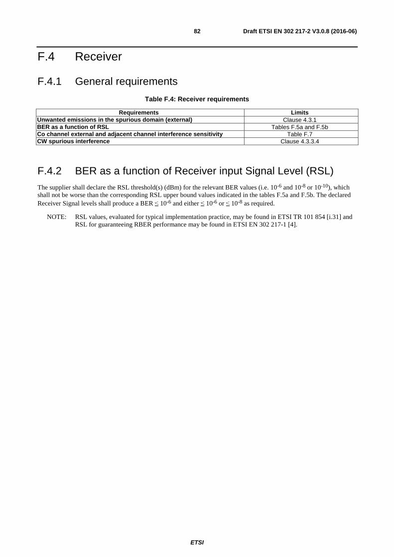
ETSI
Draft ETSI EN 302 217-2 V3.0.8 (2016-06)82
F.4 Receiver
F.4.1 General requirements
Table F.4: Receiver requirements
Requirements Limits Unwanted emissions in the spurious domain (external) Clause 4.3.1 BER as a function of RSL Tables F.5a and F.5b Co channel external and adjacent channel interference sensitivity Table F.7 CW spurious interference Clause 4.3.3.4
F.4.2 BER as a function of Receiver input Signal Level (RSL) The supplier shall declare the RSL threshold(s) (dBm) for the relevant BER values (i.e. 10-6 and 10-8 or 10-10), which shall not be worse than the corresponding RSL upper bound values indicated in the tables F.5a and F.5b. The declared Receiver Signal levels shall produce a BER ≤ 10-6 and either ≤ 10-6 or ≤ 10-8 as required.
NOTE: RSL values, evaluated for typical implementation practice, may be found in ETSI TR 101 854 [i.31] and RSL for guaranteeing RBER performance may be found in ETSI EN 302 217-1 [4].
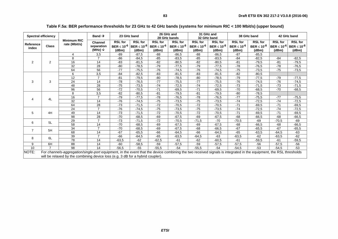
ETSI
Draft ETSI EN 302 217-2 V3.0.8 (2016-06)83
Table F.5a: BER performance thresholds for 23 GHz to 42 GHz bands (systems for minimum RIC < 100 Mbit/s) (upper bound)
Spectral efficiency Minimum RIC rate (Mbit/s)
Band � 23 GHz band 26 GHz and 28 GHz bands
31 GHz and 32 GHz band 38 GHz band 42 GHz band
Reference index Class
Channel separation
(MHz) �
RSL for BER ≤ 10-6
(dBm)
RSL for BER ≤ 10-8
(dBm)
RSL for BER ≤ 10-6
(dBm)
RSL for BER ≤ 10-8
(dBm)
RSL for BER ≤ 10-6
(dBm)
RSL for BER ≤ 10-8
(dBm)
RSL for BER ≤ 10-6
(dBm)
RSL for BER ≤ 10-8
(dBm)
RSL for BER ≤ 10-6
(dBm)
RSL for BER ≤ 10-8
(dBm)
2 2
4 3,5 -89 -87,5 -88 -86,5 -88 -86,5 -87 -85,5 8 7 -86 -84,5 -85 -83,5 -85 -83,5 -84 -82,5 -84 -82,5
16 14 -83 -81,5 -82 -80,5 -82 -80,5 -81 -79,5 -81 -79,5 32 28 -80 -78,5 -79 -77,5 -79 -77,5 -78 -76,5 -78 -76,5 64 56 -77 -75,5 -76 -74,5 -76 -74,5 -75 -73,5 -75 -73,5
3 3
6 3,5 -84 -82,5 -83 -81,5 -83 -81,5 -82 -80,5 12 7 -81 -79,5 -80 -78,5 -80 -78,5 -79 -77,5 -79 -77,5 24 14 -78 -76,5 -77 -75,5 -77 -75,5 -76 -74,5 -76 -74,5 48 28 -75 -73,5 -74 -72,5 -74 -72,5 -73 -71,5 -73 -71,5 96 56 -72 -70,5 -71 -69,5 -71 -69,5 -70 -68,5 -70 -68,5
4 4L
8 3,5 -82 -80,5 -81 -79,5 -81 -79,5 -80 -78,5 16 7 -79 -77,5 -78 -76,5 -78 -76,5 -77 -75,5 -77 -75,5 32 14 -76 -74,5 -75 -73,5 -75 -73,5 -74 -72,5 -74 -72,5 64 28 -73 -71,5 -72 -70,5 -72 -70,5 -71 -69,5 -71 -69,5
5 4H 24 7 -76 -74,5 -75 -73,5 -75 -73,5 -74 -72,5 -74 -72,5 49 14 -73 -71,5 -72 -70,5 -72 -70,5 -71 -69,5 -71 -69,5 98 28 -70 -68,5 -69 -67,5 -69 -67,5 -68 -66,5 -68 -66,5
6 5L 29 7 -73 -71,5 -72 -70,5 -71,5 -70 -70,5 -69 -70,5 -69 58 14 -70 -68,5 -69 -67,5 -69 -67,5 -68 -66,5 -68 -66,5
7 5H 34 7 -70 -68,5 -69 -67,5 -68 -66,5 -67 -65,5 -67 -65,5 68 14 -67 -65,5 -66 -64,5 -66 -64,5 -65 -63,5 -64,5 -63
8 6L 39 7 -66 -64,5 -65 -63,5 -64,5 -63 -63,5 -62 -63,5 -62 78 14 -63,5 -62 -62,5 -61 -62 -60,5 -61 -59,5 -61 -59,5
9 6H 88 14 -60 -58,5 -59 -57,5 -59 -57,5 -57,5 -56 -57,5 -56 10 7 98 14 -56,5 -55 -55,5 -54 -55,5 -54 -54,5 -53 -54,5 -53
NOTE: For channels-aggregation/single-port equipment, in the event that the device combining the two received signals is integrated in the equipment, the RSL thresholds will be relaxed by the combining device loss (e.g. 3 dB for a hybrid coupler).

ETSI
Draft ETSI EN 302 217-2 V3.0.8 (2016-06)84
Table F.5b: BER performance thresholds for 23 GHz to 42 GHz bands (systems for minimum RIC ≥ 100 Mbit/s) (upper bound)
Spectral efficiency Minimum RIC rate (Mbit/s)
Band � 23 GHz band 26 GHz and 28 GHz bands
31 GHz and 32 GHz band 38 GHz band 42 GHz band
Reference index Class
Channel separation
(MHz) �
RSL for BER ≤ 10-6
(dBm)
RSL for BER ≤ 10-10
(dBm)
RSL for BER ≤ 10-6
(dBm)
RSL for BER ≤ 10-10
(dBm)
RSL for BER ≤ 10-6
(dBm)
RSL for BER ≤ 10-10
(dBm)
RSL for BER ≤ 10-6
(dBm)
RSL for BER ≤ 10-10
(dBm)
RSL for BER ≤ 10-6
(dBm)
RSL for BER ≤ 10-10
(dBm) 2 2 128 112 -74 -71 -73 -70 -73 -70 -72 -69 -72 -69 3 3 191 112 -69 -66 -68 -65 -68 -65 -67 -64 -67 -64
4 4L 128 56 -70 -67 -69 -66 -69 -66 -68 -65 -68 -65 256 112 -67 -64 -66 -63 -66 -63 -65 -62 -65 -62
5 4H 196 56 -67 -64 -66 -63 -66 -63 -65 -62 -65 -62 392 112 -64 -61 -63 -60 -63 -60 -62 -59 -62 -59
6 5LA/5LB 117 28 -67 -64 -66 -63 -66 -63 -65 -62 -65 -62 235 56 -64 -61 -63 -60 -63 -60 -62 -59 -62 -59 470 112 -61 -58 -60 -57 -60 -57 -59 -56 -59 -56
7 5HA/5HB 137 28 -64 -61 -63 -60 -63 -60 -62 -59 -62 -59
274 (note) 56 -61 -58 -60 -57 -60 -57 -59 -56 -59 -56 548 112 -58 -55 -57 -54 -57 -54 -56 -53 -56 -53
8 6LA/6LB 156 28 -61 -58 -60 -57 -59,5 -56,5 -58,5 -55,5 -58,5 -55,5 313 56 -58 -55 -57 -54 -57 -54 -56 -53 -56 -53 627 112 -55 -52 -54 -51 -54 -51 -53 -50 -53 -50
9 6HA/6HB 176 28 -57,5 -54,5 -56,5 -53,5 -56 -53 -55 -52 -55 -52 352 56 -55 -52 -54 -51 -53,5 -50,5 -52,5 -49,5 -52,5 -49,5 705 112 -52 -49 -51 -48 -51 -48 -50 -47 -50 -47
10 7A/7B 196 28 -54 -51 -53 -50 -52,5 -49,5 -51,5 -48,5 -51,5 -48,5 392 56 -51,5 -48,5 -50,5 -47,5 -50 -47 -49 -46 -49 -46 784 112 -49 -46 -48 -45 -47,5 -44,5 -46,5 -43,5 -46,5 -43,5
11 8A/8B
107 14 -53,5 -50,5 -52,5 -49,5 -52,5 -49,5 -51,5 -48,5 -51,5 -48,5 215 28 -50,5 -47,5 -49,5 -46,6 -49,5 -46,5 -48,5 -45,5 -48,5 -45,5 431 56 -48 -45 -47 -44 -46,5 -43,5 -46 -43 -46 -43 862 112 -45,5 -42,5 -44,5 -41,5 -44 -41 -43 -40 -43 -40
NOTE: For channels-aggregation/single-port equipment, in the event that the device combining the two received signals is integrated in the equipment, the RSL thresholds will be relaxed by the combining device loss (e.g. 3 dB for a hybrid coupler).

ETSI
Draft ETSI EN 302 217-2 V3.0.8 (2016-06)85
F.4.3 Co-channel "external" and adjacent channel interference sensitivity
The limits of Carrier to Interference ratio (C/I) in case of co-channel and adjacent channel interference shall be as in table F.6, giving maximum C/I values for 1 dB and 3 dB degradation of the RSL limits declared for BER ≤ 10-6 in clause F.4.2.
Table F.6: Co-channel and adjacent channel interference sensitivity
Spectral efficiency Frequency
band (GHz)
Minimum RIC rate (Mbit/s)
(see note)
Channel separation (MHz)
(see note)
C/I for BER ≤ 10-6 RSL degradation of 1 dB or 3 dB
Co-channel interference
Adjacent channel interference
Reference index Class 1 dB 3 dB 1 dB 3 dB
2 2 All except 42 4 3,5
23 19 0 -4 All 8; 16; 32; 64; 128 7; 14; 28; 56; 112
3 3 All except 42 6 3,5
23 19 -1 -5 All 12; 24; 48; 96; 191 7; 14; 28; 56; 112
4 4L All except 42 8 3,5
30 26 -1 -5 All 16; 32; 64; 128; 256 7; 14; 28; 56; 112
5 4H All 24; 49; 98; 196; 392 7; 14; 28; 56; 112 30 26 -6 -9,5
6 5L All 29; 58 7; 14 34 30 -3 -7
5LB All 117; 235; 470 28; 56; 112 (ACCP) 34 30 -3 -7 5LA All 117; 235; 470 28; 56; 112 (ACAP) 34 30 4 1
7
5H All 34; 68 7; 14 37 33 -3 -7
5HB All 137 28 (ACCP)
274; 548 56; 112 (ACCP) 37 33 -3,5 -7,5 5HA All 137; 274; 548 28; 56; 112 (ACAP) 37 33 +3 -1
8 6L All 39; 78 7; 14
40 36 0 -4 6LB All 156; 313; 627 28; 56; 112 (ACCP) 6LA All 156; 313; 627 28; 56; 112 (ACAP) 40 36 10 7
9 6H All 88 14
43 39 0 -4 6HB All 176; 352; 705 28; 56; 112 (ACCP) 6HA All 176; 352; 705 28; 56; 112 (ACAP) 43 39 10 6
10 7 All 98 14
46 42 0 -4 7B All 196; 392; 784 28; 56; 112 (ACCP) 7A All 196; 392; 784 28; 56; 112 (ACAP) 46 42 13 9
11 8 All 107 14
50 46 0 -4 8B All 215; 431; 862 28; 56; 112 (ACCP) 8A All 215; 431; 862 28; 56; 112 (ACAP) 50 46 17 13
NOTE: Minimum RIC and Channel separation series of values in each row are intended one to one coupled in their orders.
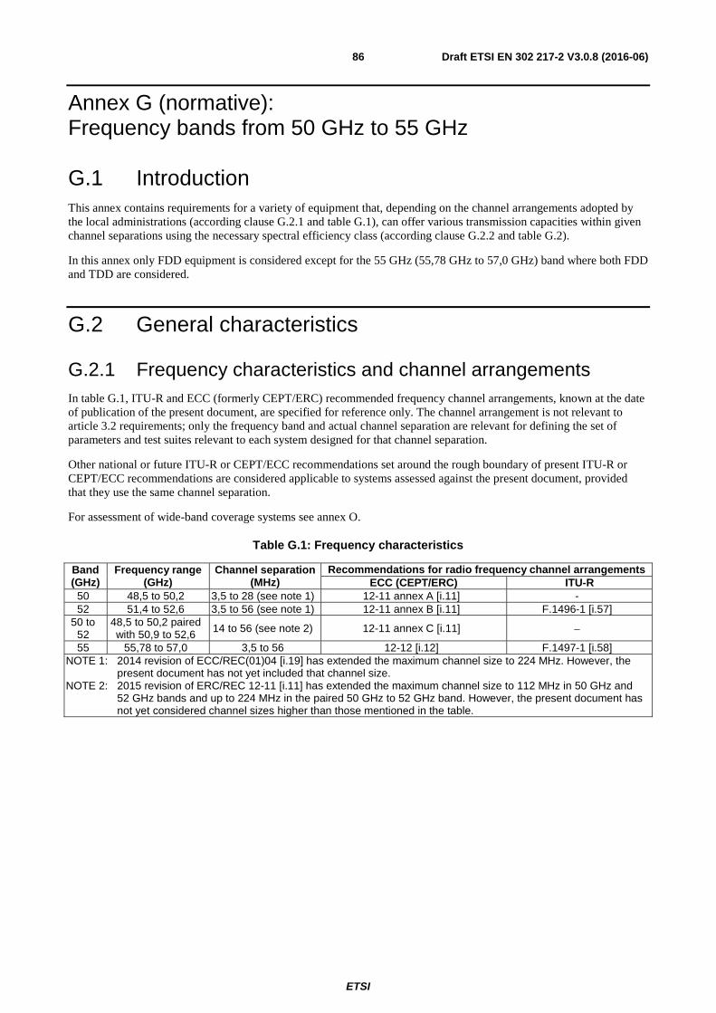
ETSI
Draft ETSI EN 302 217-2 V3.0.8 (2016-06)86
Annex G (normative): Frequency bands from 50 GHz to 55 GHz
G.1 Introduction This annex contains requirements for a variety of equipment that, depending on the channel arrangements adopted by the local administrations (according clause G.2.1 and table G.1), can offer various transmission capacities within given channel separations using the necessary spectral efficiency class (according clause G.2.2 and table G.2).
In this annex only FDD equipment is considered except for the 55 GHz (55,78 GHz to 57,0 GHz) band where both FDD and TDD are considered.
G.2 General characteristics
G.2.1 Frequency characteristics and channel arrangements In table G.1, ITU-R and ECC (formerly CEPT/ERC) recommended frequency channel arrangements, known at the date of publication of the present document, are specified for reference only. The channel arrangement is not relevant to article 3.2 requirements; only the frequency band and actual channel separation are relevant for defining the set of parameters and test suites relevant to each system designed for that channel separation.
Other national or future ITU-R or CEPT/ECC recommendations set around the rough boundary of present ITU-R or CEPT/ECC recommendations are considered applicable to systems assessed against the present document, provided that they use the same channel separation.
For assessment of wide-band coverage systems see annex O.
Table G.1: Frequency characteristics
Band (GHz)
Frequency range (GHz)
Channel separation (MHz)
Recommendations for radio frequency channel arrangements ECC (CEPT/ERC) ITU-R
50 48,5 to 50,2 3,5 to 28 (see note 1) 12-11 annex A [i.11] - 52 51,4 to 52,6 3,5 to 56 (see note 1) 12-11 annex B [i.11] F.1496-1 [i.57]
50 to 52
48,5 to 50,2 paired with 50,9 to 52,6 14 to 56 (see note 2) 12-11 annex C [i.11] −
55 55,78 to 57,0 3,5 to 56 12-12 [i.12] F.1497-1 [i.58] NOTE 1: 2014 revision of ECC/REC(01)04 [i.19] has extended the maximum channel size to 224 MHz. However, the
present document has not yet included that channel size. NOTE 2: 2015 revision of ERC/REC 12-11 [i.11] has extended the maximum channel size to 112 MHz in 50 GHz and
52 GHz bands and up to 224 MHz in the paired 50 GHz to 52 GHz band. However, the present document has not yet considered channel sizes higher than those mentioned in the table.

ETSI
Draft ETSI EN 302 217-2 V3.0.8 (2016-06)87
G.2.2 Transmission capacities
Table G.2: Minimum RIC transmission capacity and system classes for various channel separation
Channel arrangement � Co-polar (ACCP) Cross-polar (ACAP) Channel separation (MHz) � 3,5 7 14 28 56 112 28 56 112
Min
imu
m p
aylo
ad R
IC r
ate
Mb
it/s
(n
ote
)
Spectral efficiency � Frequency
band (GHz) �
� �
� �
� �
� �
� �
� �
� �
� �
� � Reference
index Class
1 1 50 2 - - - - - - -
52; 55 2 4 8 16 32 - - -
2 2 50 4 8 16 32 - - - - -
52; 55 4 8 16 32 64 - - - -
3 3 50 6 12 24 48 - - - - -
52; 55 6 12 24 48 96 - - - -
4 4L 50 8 16 32 64 - - - - -
52; 55 8 16 32 64 128 - - - - NOTE: For equipment assessment with different base band interfaces see annex N.
G.3 Transmitter
G.3.1 General requirements
Table G.3: Transmitter requirements
Requirements Limits Maximum transmitter power Clause 4.2.1.1 Nominal transmitter power tolerance Clause 4.2.1.3 Transmitter power and frequency control Clause 4.2.2 RF Spectrum power density mask Clause 4.2.3.2 Discrete CW components exceeding the spectrum mask limit Clause 4.2.4 Unwanted emissions in the spurious domain - external Clause 4.2.5 Dynamic Change of Modulation Order Clause 4.2.6 Radio frequency tolerance Clause 4.2.7
G.3.2 RF spectrum masks The masks in clause 4.2.3.2 are valid only for those specific combinations of CS, nominal capacity and spectral efficiency class that are also included among those foreseen in table G.2.
G.4 Receiver
G.4.1 General requirements
Table G.4: Receiver requirements
Requirements Limits Unwanted emissions in the spurious domain (external) Clause 4.3.1 BER as a function of RSL Table G.6 Co channel external and adjacent channel interference sensitivity Table G.7 CW spurious interference Clause 4.3.3.4

ETSI
Draft ETSI EN 302 217-2 V3.0.8 (2016-06)88
G.4.2 BER as a function of Receiver input Signal Level (RSL) The supplier shall declare the RSL threshold(s) (dBm) for the relevant BER values (i.e. 10-6 and 10-8 or 10-10), which shall not be worse than the corresponding RSL upper bound values indicated in table G.5. The declared Receiver Signal levels shall produce a BER ≤ 10-6 and either ≤ 10-6 or ≤ 10-10 as required.
NOTE: RSL values, evaluated for typical implementation practice, may be found in ETSI TR 101 854 [i.31] and RSL for guaranteeing RBER performance may be found in ETSI EN 302 217-1 [4].
Table G.5: BER performance thresholds for 50 GHz to 55 GHz (upper bound)
Spectral efficiency Minimum
RIC rate (Mbit/s)
Band � 50 GHz 50 and 52 GHz Paired 52 GHz and 55 GHz
Reference index Class
Channel separation
(MHz) �
RSL for BER ≤
10-6(dBm)
RSL for BER ≤
10-8(dBm)
RSL for BER ≤
10-10(dBm)
RSL for BER ≤
10-6(dBm)
RSL for BER ≤
10-8(dBm)
RSL for BER ≤
10-10(dBm)
1 1
2 3,5 -89 -87,5 - -88 -86,5 - 4 7 - - - -85 -83,5 - 8 14 - - - -82 -80,5 - 16 28 - - - -79 -77,5 - 32 56 - - - -76 -74,5 -
2 2
4 3,5 -86 -84,5 - -85 -83,5 - 8 7 -83 -81,5 - -82 -80,5 - 16 14 -80 -78,5 - -79 -77,5 - 32 28 -77 -75,5 - -76 -74,5 - 64 56 -74 -72,5 - -73 -71,5 -
3 3
6 3,5 -80,5 -79 - -79,5 -78 - 12 7 -77,5 -76 - -76,5 -75 24 14 -74,5 -73 - -73,5 -72 48 28 -71,5 -70 - -70,5 -69 96 56 -68,5 -67 - -67,5 -66
4 4L
8 3,5 -78,5 -77 - -77,5 -76 - 16 7 -75,5 -74 - -74,5 -73 - 32 14 -73 -71,5 - -72 -70,5 - 64 28 -70 -68,5 - -69 -67,5 -
128 56 -67 -64 -66 - -63 NOTE: For channels-aggregation/single-port equipment, in the event that the device combining the two received signals
is integrated in the equipment, the RSL thresholds will be relaxed by the combining device loss (e.g. 3 dB for a hybrid coupler).
G.4.3 Co-channel "external" and adjacent channel interference sensitivity
The limits of Carrier to Interference ratio (C/I) in case of co-channel and adjacent channel interference shall be as in table G.6, giving maximum C/I values for 1 dB and 3 dB degradation of the RSL limits declared for BER ≤ 10-6 in clause G.4.2.
Table G.6: Co-channel and adjacent channel interference sensitivity
Spectral efficiency Frequency
band (GHz)
Minimum RIC rate (Mbit/s)
(see note)
Channel separation (MHz)
(see note)
C/I for BER ≤ 10-6 RSL degradation of 1 dB or 3 dB
Co-channel interference
Adjacent channel interference
Reference index Class 1 dB 3 dB 1 dB 3 dB
1 1 All 2; 4; 8; 16; 32 3,5; 7; 14; 28; 56 23 19 0 -4 2 2 All 4; 8; 16; 32; 64 3,5; 7; 14; 28; 56 23 19 0 -4 3 3 All 6, 12; 24; 48; 96 3,5; 7; 14; 28; 56 23 19 -1 -5 4 4L All 8; 16; 32; 64; 128 3,5; 7; 14; 28; 56 30 26 -1 -5
NOTE: Minimum RIC and Channel separation series of values in each row are intended one to one coupled in their orders.

ETSI
Draft ETSI EN 302 217-2 V3.0.8 (2016-06)89
Annex H (normative): Frequency band 57 GHz to 66 GHz
H.1 Introduction Both FDD and TDD applications are covered in this annex.
The frequency arrangement in the whole frequency range covered in this annex is derived from the ECC/Recommendation (09)01 [i.24] (for the band 57 GHz to 64 GHz) and ECC/Recommendation (05)02 [i.23] (for the band 64 GHz to 66 GHz) when the latter is used in conjunction to the first with same 50 MHz slots.
According those recommendations, administrations may choose either to allow assignments in this band without a specific channel arrangement, or establish an arrangement based on simplified frequency slots arrangement.
This annex refers to systems based on CS = n × 50 MHz, with 1 ≤ n ≤ 40; systems not designed according that CS granularity should refer to the closest CS closest to their occupied bandwidth.
NOTE: In the frequency band 64 GHz to 66 GHz the less stringent emission requirements referred in annex I can also be applied. The manufacturer should select the more appropriate according to the actual system and application foreseen.
The upper (64,0 GHz to 66,0 GHz) portions of this band are included within the High Density Fixed Service (HDFS) bands referred in the Radio Regulations [7].
H.2 General characteristics
H.2.1 Frequency characteristics and channel arrangements In table H.1, ITU-R and ECC (formerly CEPT/ERC) recommended frequency channel arrangements, known at the date of publication of the present document, are specified for reference only. The channel arrangement is not relevant to article 3.2 of the Directive 2014/53/EU [i.1] requirements; only the frequency band and actual channel separation are relevant for defining the set of parameters and test suites relevant to each system mainly designed for that channel separation and that frequency band.
Other national or future ITU-R or CEPT/ECC recommendations set around the rough boundary of present ITU-R or CEPT/ECC recommendations are considered applicable to systems assessed against the present document, provided that they use the same channel separation.
For assessment of wide-band coverage systems see annex O.
Table H.1: Frequency characteristics
Band (GHz)
Frequency range (GHz)
Channel separation (MHz)
Recommendations for radio frequency channel arrangements
ECC ITU-R 57 to 64 57 to 64 50 to 2 000 (see note) (09)01 [i.24] Annex 2 of F.1497-2 [i.58] 64 to 66 64 to 66 50 to 2 000 (see note) (05)02 [i.23] Annex 3.2 of F.1497-2 [i.58] NOTE: In steps of n × 50 MHz; systems not designed according specific channel arrangement shall declare the
occupied bandwidth and should refer to the closest n × 50 MHz channel separation.
H.2.2 Transmission capacities Table H.2 gives the minimum RIC as function of spectral efficiency class and CS; specific values are given for the minimum and maximum CS foreseen for each class, while, for intermediate N × 50 MHz CS, only parametric formula is given; values of (RIC) in brackets are intermediate CS reference only.

ETSI
Draft ETSI EN 302 217-2 V3.0.8 (2016-06)90
Table H.2: Minimum RIC transmission capacity and system classes for various channel separation
Channel separation (MHz) � 50 N × 50 (N < 40)
500 (N = 10) 750 (N = 15) 1 250 (N = 25) 2 000 (N = 40)
Min
imu
m p
aylo
ad R
IC r
ate
Mb
it/s
(n
ote
1)
Spectral efficiency � � �
� �
� �
� �
� �
� � Reference
index Class
1 1 28,5 28,5 × N (note 2)
(285) (427) (712) 1 140
2 2 57 57 × N (570) (855) (1 425) 2 280 3 3 85 85 × N (850) (1 275) (2 125) 3 400
4 4L 114 114 × N (note 3)
(1 140) (1 710) 2 850 -
5 4H 175 175 × N (note 4)
(1 750) 2 625 - -
6 5LA/5LB 210 210 × N (note 4)
(2 100) 3 150 - -
7 5HA/5HB 245 245 × N (note 5)
2 450 - - -
8 6LA/6LB 280 280 × N (note 5)
2 800 - - -
NOTE 1: For equipment assessment with different base band interfaces see annex N. NOTE 2: For N > 4 rounded down to the lower Mbit/s integer. NOTE 3: N < 25. NOTE 4: N < 15. NOTE 5: N < 10.
H.3 Transmitter
H.3.1 General requirements Table H.3 summarises the TX requirements.
Table H.3: Transmitter requirements
Requirements Limits Combined TX power output and EIRP limits Clause H.3.2.2 or clause H.3.2.3 Nominal transmitter power tolerance Clause 4.2.1.3 Transmitter power and frequency control Clause 4.2.2 RF Spectrum power density mask Clause 4.2.3.2 Emissions outside the 57 GHz to 66 GHz range Clause H.3.4 Discrete CW components exceeding the spectrum mask limit Clause 4.2.4 Unwanted emissions in the spurious domain - external Clause 4.2.5 Dynamic Change of Modulation Order Clause 4.2.6 Radio frequency tolerance Clause 4.2.7
H.3.2 Combined TX power output and EIRP limits
H.3.2.1 Maximum power and EIRP
The following transmitter output power, antenna gain and EIRP limits are set by ECC/REC(09)01 [i.24] for the 57 GHz to 64 GHz band:
• Maximum EIRP: +55 dBm.
• Minimum antenna gain: +30 dBi.
• Maximum transmitter output power: +10 dBm.

ETSI
Draft ETSI EN 302 217-2 V3.0.8 (2016-06)91
ECC/REC(05)02 [i.23] does not fix any limit for the band 64 GHz to 66 GHz; therefore, only the generic limits for terrestrial stations set in the article 21 of Radio Regulations [7] apply.
In addition, in order of safeguarding a fair and efficient use of the spectrum, maximum Pout and EIRP emissions (referred in clause 4.2.1.1 and clause 4.2.1.2) of equipment in the scope of the present document, and operating in the range 57 GHz to 64 GHz, shall be limited as in following clauses as function of the antenna gain (Gant).
Equipment that can operate in the whole range 57 GHz to 66 GHz should select, for the range 64 GHz to 66 GHz only, either to apply for commonality the same limitation or that less restrictive given in clause I.3.2 of annex I.
H.3.2.2 Equipment without ATPC as permanent feature
These are equipment that, even if ATPC is implemented, it can be freely enabled, disabled and/or preset by the user.
• Equipment with integral antennas or dedicated antennas
1a) EIRP (dBm) ≤ +55 for Gant≥ 45 dBi.
≤ +10 + Gant (dBi) for 45 dBi > Gant ≥ 38 dBi.
≤ -28 + 2 × Gant (dBi) for 38 dBi > Gant ≥ 30 dBi.
2a) EIRP density (dBm/MHz) ≤ -10 dBm/MHz + Gant (dBi).
3a) Minimum Gant (dBi) ≥ 30.
The above limitations automatically imply (see figure H.1) also a limit to the maximum Pout:
4a) Pout (dBm) ≤ Gant - 28 for 30 dBi ≤ Gant < 38 dBi ≤ +10 for 38 dBi ≤ Gant < 45 dBi ≤ 55 - Gant for Gant ≥ 45 dBi.
• Equipment offering external antenna connectors (see note)
For equipment offering only an external antenna connectors (i.e. fitted for the use of a stand alone antenna) the above limitation should be translated in terms of maximum output power and range of antenna gain that the manufacturer should state (see note) for the use with the equipment for not exceeding the above EIRP limitations, i.e.:
1b) Pout ≤ +10 dBm.
2b) Pout density ≤ -10 dBm/MHz.
3b) Minimum Gant (dBi) ≥ Pout (dBm) +30; or ≥ 30 (dBi) (whichever is the greater).
4b) Maximum Gant (dBi) ≤ 55 - Pout (dBm) where Pout is the maximum possible power, including tolerances, delivered to the antenna connector.
NOTE: It is assumed that the above information on antenna gain range, not specifically relevant to article 3.2 of the Directive 2014/53/EU [i.1], is supplied in the user instructions as specified in article 10.8 of the Directive 2014/53/EU [i.1].
The above limitations are visually represented in figures H.1 and H.2.
H.3.2.3 Equipment implementing ATPC as permanent feature
With the term "permanent feature" it shall be intended that ATPC cannot be disabled by the user or, whenever it is possible, the maximum output power delivered, in any conditions, cannot be set to a value exceeding clause H.3.2.2 provisions 1a, 2a, 3a and 4a (or 1b, 2b, 3b and 4b as appropriate). More information on the use of ATPC may be found in ETSI TR 103 103 [i.35].

ETSI
Draft ETSI EN 302 217-2 V3.0.8 (2016-06)92
Equipment implementing ATPC as a permanent feature, linearly activated by the drop of RSL in the corresponding far end receiver, should respect the following limitations:
• Equipment with integral antennas or dedicated antennas
EIRP and Pout in full power ATPC regime:
1aATPC) EIRP (dBm) ≤ +10 + Gant (dBi); or
≤ +55 (whichever is the lower).
2aATPC) EIRP density (dBm/MHz) ≤ -10 dBm/MHz + Gant (dBi).
3aATPC) Minimum Gant (dBi) ≥ 30.
The above limitations automatically imply (see figure H.1) also a limit to the maximum Pout in full power ATPC regime:
4aATPC) Pout (dBm) ≤ +10 for 30 dBi ≤ Gant < 45 dBi
≤ 55 - Gant for Gant ≥ 45 dBi.
5aATPC) Minimum ATPC attenuation (dB) ≥ actual Pout (max delivered in
full power ATPC regime) - max Pout (from formula 4a, clause H.3.2.1).
• Equipment offering external antenna connectors (see note)
For equipment offering external antenna connectors the above limitation should be translated in terms of range of antenna gain that the manufacturer shall state for the use with the equipment (see note) for not exceeding the above EIRP limitations, i.e.:
1bATPC) Pout (dBm) ≤ +10 (in any conditions) (see note).
2bATPC) Pout density ≤ -10 dBm/MHz.
3bATPC) Minimum Gant (dBi) ≥ Pout (dBm) + 30 or
≥ 30 (dBi) (whichever is the greater) where Pout is intended as the maximum delivered by ATPC regime in unfaded condition.
4bATPC) Maximum Gant (dBi) ≤ 55 - Pout (dBm)
where Pout is intended as the maximum delivered in full power ATPC regime.
5bATPC) Minimum ATPC attenuation (dB) ≥ actual Pout (max delivered in
full power ATPC regime) - max Pout (from formula 4a, clause H.3.2.1)
NOTE: It is assumed that the above information on antenna gain range, not specifically relevant to article 3.2 of the Directive 2014/53/EU [i.1], is supplied in the user instructions as specified in article 10.8 of the Directive 2014/53/EU [i.1]. In addition, it should be considered that the Pout limits are generic absolute maximum, but, when coupled with actual antenna within minimum/maximum Gant range described in formulas 3bATPC and 4bATPC, this implies that are also satisfied the limitations expressed in formula 4a
(clause H.3.2.2) for the Pout in unfaded conditions and in formula 4aATPC (present clause) for the Pout in
ATPC regime.
The above limitations are visually represented in figures H.1 and H.2.
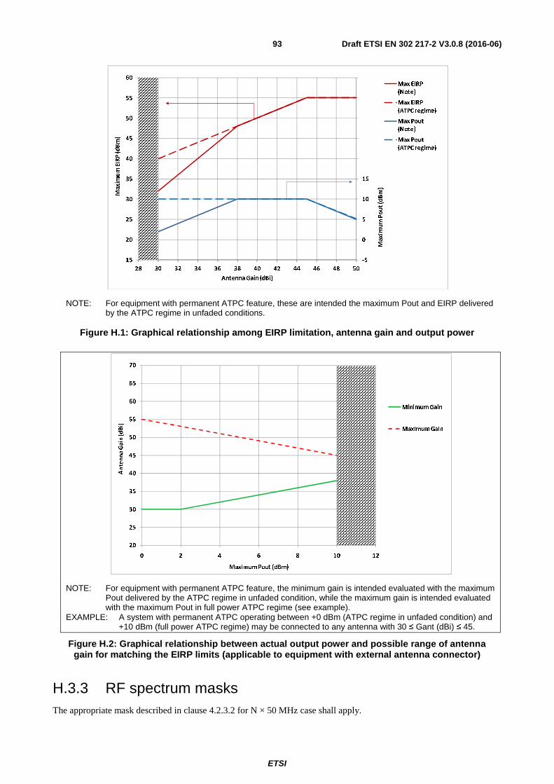
ETSI
Draft ETSI EN 302 217-2 V3.0.8 (2016-06)93
NOTE: For equipment with permanent ATPC feature, these are intended the maximum Pout and EIRP delivered by the ATPC regime in unfaded conditions.
Figure H.1: Graphical relationship among EIRP limitation, antenna gain and output power
NOTE: For equipment with permanent ATPC feature, the minimum gain is intended evaluated with the maximum Pout delivered by the ATPC regime in unfaded condition, while the maximum gain is intended evaluated with the maximum Pout in full power ATPC regime (see example).
EXAMPLE: A system with permanent ATPC operating between +0 dBm (ATPC regime in unfaded condition) and +10 dBm (full power ATPC regime) may be connected to any antenna with 30 ≤ Gant (dBi) ≤ 45.
Figure H.2: Graphical relationship between actual output power and possible range of antenna gain for matching the EIRP limits (applicable to equipment with external antenna connector)
H.3.3 RF spectrum masks The appropriate mask described in clause 4.2.3.2 for N × 50 MHz case shall apply.
-5
0
5
10
15
20
25
30
35
40
15
20
25
30
35
40
45
50
55
60
28 30 32 34 36 38 40 42 44 46 48 50
Maximum Pout (dBm)
Maximum EIRP (dBm)
Antenna Gain (dBi)
Max EIRP
(Note)
Max EIRP
(ATPC regime)
Max Pout
(Note)
Max Pout
(ATPC regime)
20
25
30
35
40
45
50
55
60
65
70
0 2 4 6 8 10 12
Antenna Gain (dBi)
Maximum Pout (dBm)
Minimum Gain
Maximum Gain

ETSI
Draft ETSI EN 302 217-2 V3.0.8 (2016-06)94
H.3.4 Emissions outside the 57 GHz to 66 GHz range Besides respecting the relevant spectrum mask in clause H.3.3, the occupied bandwidth (see definitions in ETSI EN 302 217-1 [4]) shall remain within the specified band 57 GHz to 66 GHz.
However, out-of-band emissions (i.e. those within the spectrum masks required in clause H.3.3) of systems operating close to the 57 GHz to 66 GHz band edges, may still fall outside the band edges (see note 1). Consequently, the EIRP spectral density, within the spectrum density mask frequency boundaries, eventually falling outside of the 57 GHz to 66 GHz band edges shall be further limited (see note 2) to a maximum of:
• +10 dBm/MHz.
This requirement does not imply any specific test assessment; compliance evaluation is based on nominal equipment emission characteristics and user instructions (see note 2).
NOTE 1: The ECC channel arrangements in the range 57 GHz to 66 GHz are based only on continuous raster of elementary frequency slots and do not provide variable guard bands consistent with the actual CS used, as typically done for bands below 57 GHz; hence the need for this safeguard for the larger CS.
NOTE 2: It is assumed that the above limitation implies (e.g. under article 10.8 of the Directive 2014/53/EU [i.1]) the inclusion in the user instructions of specific instructions on how to meet the requirement (e.g. minimum distance of the carrier from the band edges and/or maximum EIRP, etc.).
This shall not be intended as a relaxation of either the emission mask foreseen in clause H.3.3 or of the emissions in the spurious domain of clause 4.2.5.
H.4 Receiver
H.4.1 General requirements Table H.4 summarizes the RX requirements.
Table H.4: Receiver requirements
Requirements Limits Unwanted emissions in the spurious domain (External) Clause 4.3.1 BER as a function of RSL Clause H.4.2 Co channel external and adjacent channel interference sensitivity Clause H.4.3 CW spurious interference Clause 4.3.3.4
H.4.2 BER as a function of Receiver input Signal Level (RSL) The supplier shall declare the RSL threshold(s) (dBm) for the relevant BER values (i.e. 10-6 and 10-8 or 10-10), which shall not be worse than the corresponding RSL upper bound values indicated in table H.5. The declared Receiver Signal levels shall produce a BER ≤ 10-6 or either ≤ 10-8 or ≤ 10-10.
NOTE: RSL values, evaluated for typical implementation practice, may be found in ETSI TR 101 854 [i.31] and RSL for guaranteeing RBER performance may be found in ETSI EN 302 217-1 [4].
Table H.5: BER as a function of receiver input signal level RSL (upper bound)
Spectral efficiency Minimum RIC rate
(Mbit/s) Channel separation
(MHz)
RSL for BER ≤ 10-6 (dBm)
(see note 2)
RSL for BER ≤ 10-10
(dBm) (see note 2)
Reference index Class
1 1
28,5 50 -73 -71 28,5 × N (N < 40)
(see note 1) N × 50 (N < 40) -73 + 10logN -71 + 10logN
1 140 2 000 (N = 40) -57 -55

ETSI
Draft ETSI EN 302 217-2 V3.0.8 (2016-06)95
Spectral efficiency Minimum RIC rate
(Mbit/s) Channel separation
(MHz)
RSL for BER ≤ 10-6 (dBm)
(see note 2)
RSL for BER ≤ 10-10
(dBm) (see note 2)
Reference index Class
2 2 57 50 -71 -69
57 × N (N < 40) N × 50 (N < 40) -71 + 10logN -69 + 10logN 1 140 2 000 (N = 40) -55 -53
3 3 85 50 -68 -66
85 × N (N < 40) N × 50 (N < 40) -68 + 10logN -66 + 10logN 1 140 2 000 (N = 40) -52 -50
4 4L 114 50 -65,5 -61,5
114 × N (N < 25) N × 50 (N < 25) -65,5 + 10logN -61,5 + 10logN 2 850 1 250 (N = 25) -51,5 -47,5
5 4H 175 50 -62 -58
175 × N (N < 15) N × 50 (N < 15) -62 + 10logN -58 + 10logN 2 625 750 (N = 15) -50 -46
6 5LA/5LB 210 50 -58,5 -54,5
210 × N (N < 15) N × 50 (N < 15) -58,5 + 10logN -54,5 + 10logN 3 150 750 (N = 15) -46,5 -42,5
7 5HA/5HB 245 50 -55 -51
245 × N (N < 10) N × 50 (N < 10) -55 + 10logN -51 + 10logN 2 450 500 (N = 10) -45 -41
8 6LA/6LB 280 50 -51 -47
280 × N (N < 10) N × 50 (N < 10) -51 + 10logN -47 + 10logN 2 800 500 (N = 10) -41 -37
NOTE 1: For N > 4 rounded down to the lower Mbit/s integer. NOTE 2: Value of 10logN rounded to the closest 1/2 dB granularity. NOTE 3: For channels-aggregation/single-port equipment, in the event that the device combining the two received
signals is integrated in the equipment, the RSL thresholds will be relaxed by the combining device loss (e.g. 3 dB for a hybrid coupler).
H.4.3 Co-channel "external" and adjacent channel interference sensitivity
The limits of Carrier to Interference ratio (C/I) in case of co-channel and adjacent channel interference shall be as in table H.6, giving maximum C/I values for 1 dB and 3 dB degradation of the RSL limits declared for BER ≤ 10-6 in clause H.4.2.
Table H.6: Co-channel and adjacent channel interference sensitivity
Spectral efficiency Min. RIC rate (Mbit/s)
Channel separation
(MHz)
C/I for BER ≤ 10-6 RSL degradation of 1 dB or 3 dB
Co-channel interference
Adjacent channel interference
1 dB 3 dB 1 dB 3 dB Reference index Class
1 1 28,5 × N
(1 ≤ N ≤ 40) (see note) N × 50
(1 ≤ N ≤ 40) 23 19 0 -4
2 2 57 × N (1 ≤ N ≤ 40)
3 3 85 × N (1 ≤ N ≤ 40)
N × 50 (1 ≤ N ≤ 40)
25 21 0 -4
4 4L 114 × N (1 ≤ N ≤ 25)
N × 50 (1 ≤ N ≤ 25)
27 23 0 -4
5 4H 175 × N (1 ≤ N ≤ 15)
N × 50 (1 ≤ N ≤ 15)
30 26 -2 -6
6 5LB 210 × N
(1 ≤ N ≤ 15) N × 50 (ACCP)
(1 ≤ N ≤ 15) 33,5 29,5 -6 -10
5LA 210 × N (1 ≤ N ≤ 15)
N × 50 (ACAP) (1 ≤ N ≤ 15)
33,5 29,5 +3 -1

ETSI
Draft ETSI EN 302 217-2 V3.0.8 (2016-06)96
Spectral efficiency Min. RIC rate (Mbit/s)
Channel separation
(MHz)
C/I for BER ≤ 10-6 RSL degradation of 1 dB or 3 dB
Co-channel interference
Adjacent channel interference
1 dB 3 dB 1 dB 3 dB Reference index Class
7 5HB 245 × N
(1 ≤ N ≤ 10) N × 50 (ACCP)
(1 ≤ N ≤ 10) 37 33 -3 -7
5HA 245 × N (1 ≤ N ≤ 10)
N × 50 (ACAP) (1 ≤ N ≤ 10)
37 33 +6 +2
8 6LB 280 × N
(1 ≤ N ≤ 10) N × 50 (ACCP)
(1 ≤ N ≤ 10) 40,5 36,5 0 -4
6LA 280 × N (1 ≤ N ≤ 10)
N × 50 (ACAP) (1 ≤ N ≤ 10)
40,5 36,5 +9 +5
NOTE: RIC rounded down to closest multiple of 1 Gbit/s rate shall also be considered valid.
H.5 Minimum antenna gain According the ECC/REC(09)01 [i.24] emission limitations (see clause H.3.2.1), equipment with integral antenna or dedicated antenna shall be associated to a directional antenna with a minimum gain of 30 dBi; this value shall be respected, tolerance included.
When equipment are supplied without antenna (i.e. are fitted for a stand alone antenna), it is assumed that the above information on minimum antenna gain, not specifically relevant to equipment assessment under article 3.2 of the Directive 2014/53/EU [i.1], is indicated in the user instructions as specified in article 10.8 of the Directive 2014/53/EU [i.1].

ETSI
Draft ETSI EN 302 217-2 V3.0.8 (2016-06)97
Annex I (normative): Frequency band 64 GHz to 66 GHz
I.1 Introduction Both FDD and TDD applications are covered in this annex.
The frequency arrangement in the frequency range covered in this annex is derived from the ECC/Recommendation (05)02 [i.23].
According that recommendation administrations may choose either to allow assignments in this band without a specific channel arrangement, or establish an arrangement based on simplified frequency slots arrangement (see note 1).
This annex refers to systems based on:
• CS = n × 50 MHz, with 1 ≤ n ≤ 38 for TDD systems or 1 ≤ n ≤ 19 for FDD systems;
• CS = n × 30 MHz, with 1 ≤ n ≤ 66 for TDD systems or 1 ≤ n ≤ 33 for FDD systems;
Systems not designed according the above CS granularity should refer to the CS closest to their occupied bandwidth.
NOTE 1: Administrations might require specific measures to avoid interference (e.g. listen-before talk).
NOTE 2: In the frequency band 64 GHz to 66 GHz equipment characteristics referred in annex H may also apply. The manufacturer should select the more appropriate according to the actual system and application foreseen.
This band is included within the High Density Fixed Service (HDFS) bands referred in the Radio Regulations [7].
I.2 General characteristics
I.2.1 Frequency characteristics and channel arrangements In table I.1, ITU-R and ECC recommended frequency channel arrangements, known at the date of publication of the present document, are specified for reference only. The channel arrangement is not relevant to article 3.2 of the Directive 2014/53/EU [i.1] requirements; only the frequency band and actual channel separation are relevant for defining the set of parameters and test suites relevant to each system mainly designed for that channel separation and that frequency band.
Other national or future ITU-R or CEPT/ECC recommendations set around the rough boundary of present ITU-R or CEPT/ECC recommendations are considered applicable to systems assessed against the present document, provided that they use the same channel separation.
For assessment of wide-band coverage systems see annex O.

ETSI
Draft ETSI EN 302 217-2 V3.0.8 (2016-06)98
Table I.1: Frequency characteristics
Frequency range (GHz) Channel separation (MHz)
Recommendations for radio frequency channel arrangements
ECC (CEPT/ERC) ITU-R
64 to 66 FDD: 30 to 990 (see note 1)
TDD: 30 to 1 980 (see note 1) Annex 3 of (05)02 [i.23] Annex 3.2 of F.1497-2 [i.58]
64 to 66 FDD: 50 to 950 (see note 2) TDD: 50 to 1 900 (see note 2) Annex 3 of (05)02 [i.23] Annex 3.2 of F.1497-2 [i.58]
NOTE 1: In steps of n × 30 MHz; systems not designed according specific channel arrangement shall declare the occupied bandwidth and should refer to the closest n × 30 MHz channel separation.
NOTE 2: In steps of n × 50 MHz. FDD also extensible up to 1 950 when national regulations foresee go/return conjunction with lower band 57 GHz to 64 GHz. TDD extensible to 1 950 when the national regulations foresee.
I.2.2 Transmission capacities
I.2.2.1 Channel arrangement based on N × 50 MHz
In this case table H.2 of annex H applies taking into consideration that cases with N > 38 (TDD) or N > 19 (FDD) are not applicable; however, FDD up to N = 39 are possible when the national administration foresee use of the band in conjunction (go/return) with the lower 57 GHz to 64 GHz range.
I.2.2.2 Channel arrangement based on N × 30 MHz
Table I.2 gives the minimum RIC as function of spectral efficiency class and CS based on N × 30 MHz arrangement; specific values are given for the minimum and maximum CS foreseen for each class, while, for intermediate N × 30 MHz CS, only parametric formula is given; values of (RIC) in brackets are intermediate CS reference only.
Table I.2: Minimum RIC transmission capacity and system classes for various channel separation based on N × 30 MHz arrangement
Channel separation (MHz) � 30 N ×30
(TDD: N < 66) (FDD: N < 33)
480 (N = 16)
750 (N = 25)
990 (N = 33)
1 230 (N = 41)
1 980 (N = 66)
Min
imu
m p
aylo
ad R
IC r
ate
(Mb
it/s
) (n
ote
1)
Spectral efficiency � � �
� �
� �
� �
� �
� �
� � Reference
index Class
1 1 17 17 × N (272) (425) 561 (697) 1 122 2 2 34 34 × N (544) (850) 1 122 (1 394) 2 244 3 3 51 51 × N (816) (1 275) 1 683 (2 091) 3 366
4 4L 68 68 × N (note 2)
(1 088) (1 700) 2 244 2 788 -
5 4H 105 105 × N (note 3)
(1 680) 2 625 - - -
6 5LA/5LB 126 126 × N (note 3)
(2 016) 3 150 - - -
7 5HA/5HB 147 147 × N (note 4)
2 352 - - - -
8 6LA/6LB 168 168 × N (note 4)
2 688 - - - -
NOTE 1: For equipment assessment with different base band interfaces see annex N. NOTE 2: N < 41. NOTE 3: N < 25. NOTE 4: N < 16.

ETSI
Draft ETSI EN 302 217-2 V3.0.8 (2016-06)99
I.3 Transmitter
I.3.1 General requirements Table I.3 summarizes the TX requirements.
Table I.3: Transmitter requirements
Requirements Limits Combined TX power and EIRP limits Clause I.3.2.2 or clause I.3.2.3 Nominal transmitter power tolerance Clause 4.2.1.3 Transmitter power and frequency control Clause 4.2.2 RF Spectrum power density mask Clause 4.2.3.2 Emissions outside the 57 GHz to 66 GHz range Clause I.3.4 Discrete CW components exceeding the spectrum mask limit Clause 4.2.4 Unwanted emissions in the spurious domain -external Clause 4.2.5 Dynamic Change of Modulation Order Clause 4.2.6 Radio frequency tolerance Clause 4.2.7
I.3.2 Combined TX power and EIRP limits
I.3.2.1 Generality
ECC/REC(05)02 [i.23] does not fix any limit for the band 64 GHz to 66 GHz; therefore, only the generic limits for terrestrial stations set in the article 21 of Radio Regulations [7] apply.
Further emission limitations, in terms of EIRP and/or Pout and/or antenna gain, might be present on a national basis.
In addition, in order of safeguarding a fair and efficient use of the spectrum, maximum Pout and EIRP emissions (referred in clause 4.2.1.1 and clause 4.2.1.2) of equipment in the scope of the present document shall be limited as in following clauses as function of the antenna gain (Gant).
I.3.2.2 Equipment without ATPC as permanent feature
These are equipment that, even if ATPC is implemented, it can be freely enabled, disabled and/or preset by the user.
• Equipment with integral antenna or dedicated antennas
1a) EIRP limit (dBm) ≤ +85 (see Radio Regulation [7] article 21) for Gant ≥ 50 dBi. ≤ +85 - 2 × (50 - Gant) for 50 dBi > Gant ≥ 30 dBi.
2a) Minimum Gant (dBi) ≥ 30.
The above limitations automatically imply (see figure I.1) also a limit to the maximum Pout:
3a) Pout (dBm) ≤ Gant - 15 for 30 dBi ≤ Gant < 50 dBi ≤ 85 - Gant for Gant ≥ 50 dBi.
• Equipment offering external antenna connectors (see note)
For equipment offering only an external antenna connectors (i.e. fitted for the use of a stand alone antenna) the above limitation should be translated in terms of range of antenna gain that the manufacturer should state for the use with the equipment (see note) for not exceeding the above EIRP limitations, i.e.:
1b) Minimum Gant (dBi) ≥ Pout (dBm) + 15 or
≥ 30 (dBi) (whichever is the greater).
2b) Maximum Gant (dBi) ≤ 85 - Pout (dBm).
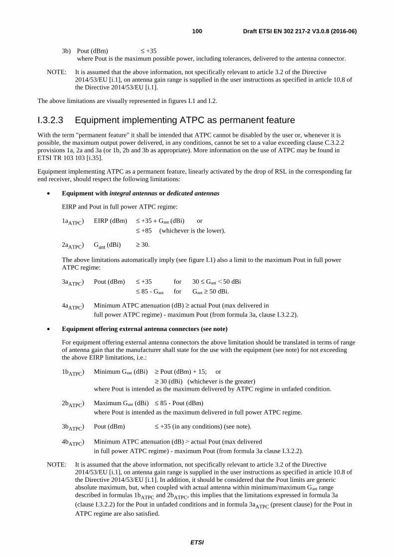
ETSI
Draft ETSI EN 302 217-2 V3.0.8 (2016-06)100
3b) Pout (dBm) ≤ +35 where Pout is the maximum possible power, including tolerances, delivered to the antenna connector.
NOTE: It is assumed that the above information, not specifically relevant to article 3.2 of the Directive 2014/53/EU [i.1], on antenna gain range is supplied in the user instructions as specified in article 10.8 of the Directive 2014/53/EU [i.1].
The above limitations are visually represented in figures I.1 and I.2.
I.3.2.3 Equipment implementing ATPC as permanent feature
With the term "permanent feature" it shall be intended that ATPC cannot be disabled by the user or, whenever it is possible, the maximum output power delivered, in any conditions, cannot be set to a value exceeding clause C.3.2.2 provisions 1a, 2a and 3a (or 1b, 2b and 3b as appropriate). More information on the use of ATPC may be found in ETSI TR 103 103 [i.35].
Equipment implementing ATPC as a permanent feature, linearly activated by the drop of RSL in the corresponding far end receiver, should respect the following limitations:
• Equipment with integral antennas or dedicated antennas
EIRP and Pout in full power ATPC regime:
1aATPC) EIRP (dBm) ≤ +35 + Gant (dBi) or
≤ +85 (whichever is the lower).
2aATPC) Gant (dBi) ≥ 30.
The above limitations automatically imply (see figure I.1) also a limit to the maximum Pout in full power ATPC regime:
3aATPC) Pout (dBm) ≤ +35 for 30 ≤ Gant ˂ 50 dBi
≤ 85 - Gant for Gant ≥ 50 dBi.
4aATPC) Minimum ATPC attenuation (dB) ≥ actual Pout (max delivered in
full power ATPC regime) - maximum Pout (from formula 3a, clause I.3.2.2).
• Equipment offering external antenna connectors (see note)
For equipment offering external antenna connectors the above limitation should be translated in terms of range of antenna gain that the manufacturer shall state for the use with the equipment (see note) for not exceeding the above EIRP limitations, i.e.:
1bATPC) Minimum Gant (dBi) ≥ Pout (dBm) + 15; or
≥ 30 (dBi) (whichever is the greater) where Pout is intended as the maximum delivered by ATPC regime in unfaded condition.
2bATPC) Maximum Gant (dBi) ≤ 85 - Pout (dBm)
where Pout is intended as the maximum delivered in full power ATPC regime.
3bATPC) Pout (dBm) ≤ +35 (in any conditions) (see note).
4bATPC) Minimum ATPC attenuation (dB) ≥ actual Pout (max delivered
in full power ATPC regime) - maximum Pout (from formula 3a clause I.3.2.2).
NOTE: It is assumed that the above information, not specifically relevant to article 3.2 of the Directive 2014/53/EU [i.1], on antenna gain range is supplied in the user instructions as specified in article 10.8 of the Directive 2014/53/EU [i.1]. In addition, it should be considered that the Pout limits are generic absolute maximum, but, when coupled with actual antenna within minimum/maximum Gant range described in formulas 1bATPC and 2bATPC, this implies that the limitations expressed in formula 3a
(clause I.3.2.2) for the Pout in unfaded conditions and in formula 3aATPC (present clause) for the Pout in
ATPC regime are also satisfied.

ETSI
Draft ETSI EN 302 217-2 V3.0.8 (2016-06)101
The above limitations are visually represented in figures I.1 and I.2.
NOTE: For equipment with permanent ATPC feature, these are intended the maximum Pout and EIRP delivered by the ATPC regime in unfaded conditions.
Figure I.1: Graphical relationship among EIRP limitation, antenna gain and output power
NOTE: For equipment with permanent ATPC feature, the minimum gain is intended evaluated with the maximum Pout delivered by the ATPC regime in unfaded condition, while the maximum gain is intended evaluated with the maximum Pout in full power ATPC regime (see example).
EXAMPLE: A system with permanent ATPC operating between +20 dBm (ATPC regime in unfaded condition) and +30 dBm (full power ATPC regime) may be connected to any antenna with 35 ≤ Gant (dBi) ≤ 55.
Figure I.2: Graphical relationship between actual output power
and possible range of antenna gain for matching the EIRP limits (applicable to equipment with external antenna connector)
10
20
30
40
50
60
70
30
40
50
60
70
80
90
28 30 32 34 36 38 40 42 44 46 48 50 52 54 56
Maximum Pout (dBm)
Maximum EIRP (dBm)
Antenna Gain (dBi)
Max EIRP
(Note)
Max EIRP
(ATPC regime)
Max Pout
(Note)
Max Pout
(ATPC regime)
20
25
30
35
40
45
50
55
60
65
70
75
80
8 10 12 14 16 18 20 22 24 26 28 30 32 34 36
Antenna Gain (dBi)
Maximum Pout (dBm)
Minimum Gain
Maximum Gain

ETSI
Draft ETSI EN 302 217-2 V3.0.8 (2016-06)102
I.3.3 RF spectrum mask The appropriate masks described in clause 4.2.3 for N × 50 MHz or for N × 30 MHz cases shall apply.
I.3.4 Emissions outside the 64 GHz to 66 GHz range Besides respecting the relevant spectrum mask in clause I.3.3, the occupied bandwidth (see definitions in ETSI EN 302 217-1 [4]) shall remain within the specified band 64 GHz to 66 GHz.
However, out-of-band emissions (i.e. those within the spectrum masks required in clause I.3.3) of systems operating close to the 64 GHz to 66 GHz band edges, may still fall outside the band edges (see note 1). Consequently, the EIRP spectral density, within the spectrum density mask frequency boundaries, eventually falling outside of the 64 GHz to 66 GHz band edges shall be further limited to a maximum of:
• +10 dBm/MHz.
This requirement does not imply any specific test assessment; compliance evaluation is based on nominal equipment emission characteristics and user instructions (see note 2).
NOTE 1: The ECC channel arrangements in the range 64 GHz to 66 GHz are based only on continuous raster of elementary frequency slots and do not provide variable guard bands consistent with the actual CS used, as typically done for bands below 57 GHz; hence the need for this safeguard for the larger CS.
NOTE 2: It is assumed that the above limitation implies (e.g. under article 10.8 of the Directive 2014/53/EU [i.1]) the inclusion in the user instructions of specific indication on how to meet the requirement (e.g. minimum distance of the carrier from the band edges and/or maximum EIRP, etc.)
This shall not be intended as a relaxation of either the emission mask foreseen in clause I.3.3 or of the emissions in the spurious domain of clause 4.2.5.
I.4 Receiver
I.4.1 General requirements Table I.4 summarizes the RX requirements.
Table I.4: Receiver requirements
Requirements Limits Unwanted emissions in the spurious domain (External) Clause 4.3.1 BER as a function of RSL Clause I.4.2 Co channel external and adjacent channel interference sensitivity Clause I.4.3 CW spurious interference Clause 4.3.3.4
I.4.2 BER as a function of Receiver input Signal Level (RSL)
I.4.2.1 Channel arrangement based on N × 50 MHz
In this case clause H.4.2 of annex H applies taking into consideration that cases with N > 38 (TDD) or N > 19 (FDD) are not applicable.
I.4.2.2 Channel arrangement based on N × 30 MHz
The supplier shall declare the RSL threshold(s) (dBm) for the relevant BER values (i.e. 10-6 and 10-8 or 10-10), which shall not be worse than the corresponding RSL upper bound values indicated in table I.5. The declared Receiver Signal levels shall produce a BER ≤ 10-6 or either ≤ 10-8 or ≤ 10-10.

ETSI
Draft ETSI EN 302 217-2 V3.0.8 (2016-06)103
NOTE: RSL for guaranteeing RBER performance may be found in ETSI EN 302 217-1 [4].
Table I.5: BER as a function of receiver input signal level RSL (upper bound)
Spectral efficiency Minimum RIC rate
(Mbit/s) Channel separation
(MHz)
RSL for BER ≤ 10-6 (dBm)
(see note 1)
RSL for BER ≤ 10-10
(dBm) (see note 1)
Reference index Class
1 1
17 30 -75,2 -73,2 17 × N (TDD: N < 66)
(FDD: N < 33) N × 30 (TDD: N < 66)
(FDD: N < 33) -75,2 + 10logN -73,2 + 10logN
561 (FDD: N = 33) 990 (FDD: N = 33) -60 -58 1 122 (TDD: N = 66) 1 980 (TDD: N = 66) -57 -55
2 2
34 30 -73,2 -71,2 34× N (TDD: N < 66)
(FDD: N < 33) N × 30 (TDD: N < 66)
(FDD: N < 33) -73,2 + 10logN -71,2 + 10logN
1 122(FDD: N = 33) 990 (FDD: N = 33) -58 -56 2 244 (TDD: N = 66) 1 980 (TDD: N = 66) -55 -53
3 3
51 30 -70,2 -68,2 51 × N (TDD: N < 66)
(FDD: N < 33) N × 30 (TDD: N < 66)
(FDD: N < 33) -70,2 + 10logN -68,2 + 10logN
1 638 (FDD: N = 33) 990 (FDD: N = 33) -55 -53 3 366 (TDD: N = 66) 1 980 (TDD: N = 66) -52 -50
4 4L
68 30 -67,7 -63,7 68 × N (TDD: N < 41)
(FDD: N < 33) N × 30 (TDD: N < 41)
(FDD: N < 33) -67,7 + 10logN -63,7 + 10logN
2 244 (FDD: N = 33) 990 (FDD: N = 33) -52,5 -48,5 2 788 (TDD: N = 41) 1 980 (TDD: N = 41) -51,5 50,5
5 4H 105 30 -64,2 -60,2
105 × N (N < 25) N × 30 (N < 25) -64,2 + 10logN -60,2 + 10logN 2 625 (N = 25) 990 (N = 25) -50,2 -46,2
6 5LA/5LB 126 30 -60,7 -56,7
126 × N (N < 25) N × 30 (N < 25) -60,7+ 10logN -56,7 + 10logN 3 150 (N = 25) 990 (N = 25) -46,7 -42,7
7 5HA/5HB 147 30 -57,2 -53,2
147 × N (N < 16) N × 30 (N < 16) -57,2 + 10logN -53,2 + 10logN 2 352 (N = 16) 480 (N = 16) -45 -41
8 6LA/6LB 168 30 -53,2 -49,2
168 × N (N < 16) N × 30 (N < 16) -53,2 + 10logN -49,2 + 10logN 2 688 (N = 16) 480 (N = 16) -41 -37
NOTE 1: Value of 10logN rounded to the closest 1/2 dB granularity. NOTE 2: For channels-aggregation/single-port equipment, in the event that the device combining the two received
signals is integrated in the equipment, the RSL thresholds will be relaxed by the combining device loss (e.g. 3 dB for a hybrid coupler).
I.4.3 Co-channel "external" and adjacent channel interference sensitivity
I.4.3.1 Channel arrangement based on N × 50 MHz
In this case clause H.4.3 of annex H applies taking into consideration that cases with N > 38 (TDD) or N > 19 (FDD) are not applicable.
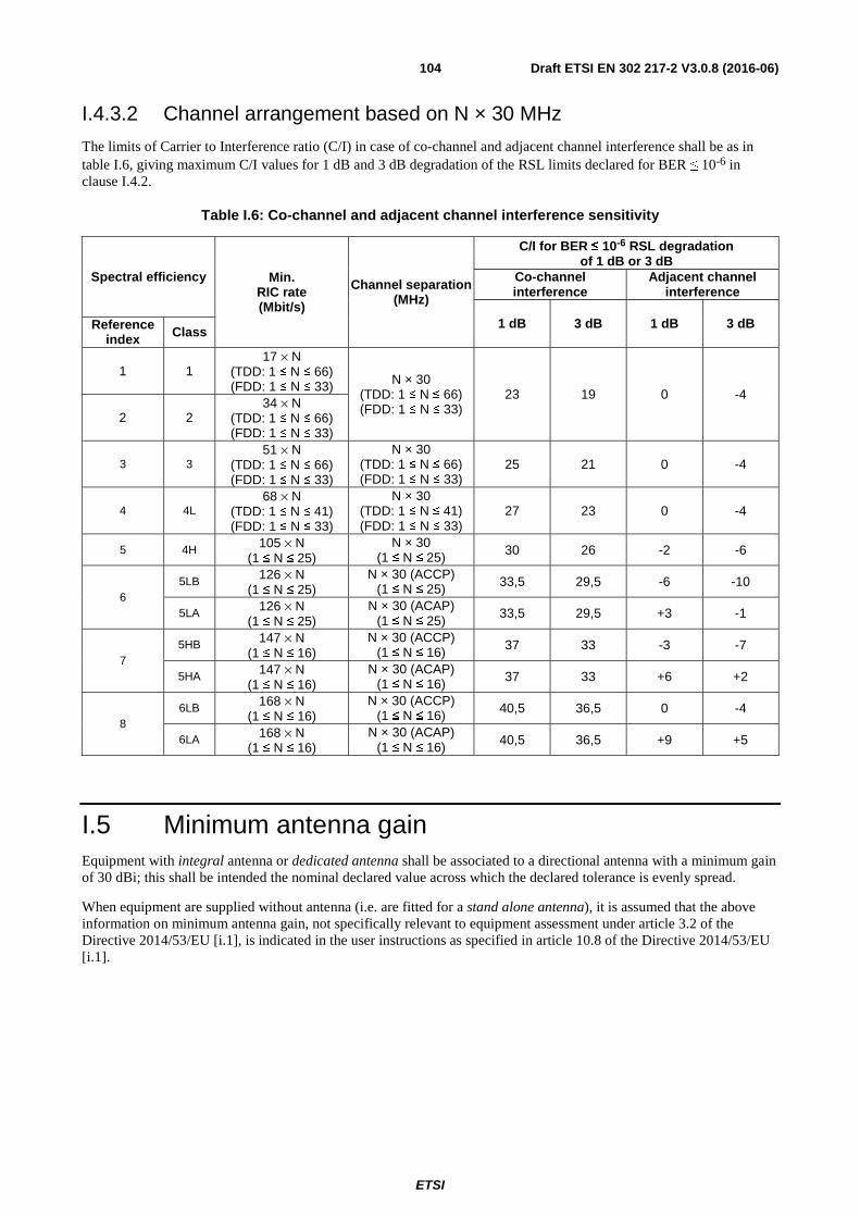
ETSI
Draft ETSI EN 302 217-2 V3.0.8 (2016-06)104
I.4.3.2 Channel arrangement based on N × 30 MHz
The limits of Carrier to Interference ratio (C/I) in case of co-channel and adjacent channel interference shall be as in table I.6, giving maximum C/I values for 1 dB and 3 dB degradation of the RSL limits declared for BER ≤ 10-6 in clause I.4.2.
Table I.6: Co-channel and adjacent channel interference sensitivity
Spectral efficiency Min. RIC rate (Mbit/s)
Channel separation (MHz)
C/I for BER ≤ 10-6 RSL degradation of 1 dB or 3 dB
Co-channel interference
Adjacent channel interference
1 dB 3 dB 1 dB 3 dB Reference index Class
1 1 17 × N
(TDD: 1 ≤ N ≤ 66) (FDD: 1 ≤ N ≤ 33) N × 30
(TDD: 1 ≤ N ≤ 66) (FDD: 1 ≤ N ≤ 33)
23 19 0 -4
2 2 34 × N
(TDD: 1 ≤ N ≤ 66) (FDD: 1 ≤ N ≤ 33)
3 3 51 × N
(TDD: 1 ≤ N ≤ 66) (FDD: 1 ≤ N ≤ 33)
N × 30 (TDD: 1 ≤ N ≤ 66) (FDD: 1 ≤ N ≤ 33)
25 21 0 -4
4 4L 68 × N
(TDD: 1 ≤ N ≤ 41) (FDD: 1 ≤ N ≤ 33)
N × 30 (TDD: 1 ≤ N ≤ 41) (FDD: 1 ≤ N ≤ 33)
27 23 0 -4
5 4H 105 × N (1 ≤ N ≤ 25)
N × 30 (1 ≤ N ≤ 25) 30 26 -2 -6
6 5LB 126 × N
(1 ≤ N ≤ 25) N × 30 (ACCP)
(1 ≤ N ≤ 25) 33,5 29,5 -6 -10
5LA 126 × N (1 ≤ N ≤ 25)
N × 30 (ACAP) (1 ≤ N ≤ 25)
33,5 29,5 +3 -1
7 5HB 147 × N
(1 ≤ N ≤ 16) N × 30 (ACCP)
(1 ≤ N ≤ 16) 37 33 -3 -7
5HA 147 × N (1 ≤ N ≤ 16)
N × 30 (ACAP) (1 ≤ N ≤ 16) 37 33 +6 +2
8 6LB 168 × N
(1 ≤ N ≤ 16) N × 30 (ACCP)
(1 ≤ N ≤ 16) 40,5 36,5 0 -4
6LA 168 × N (1 ≤ N ≤ 16)
N × 30 (ACAP) (1 ≤ N ≤ 16) 40,5 36,5 +9 +5
I.5 Minimum antenna gain Equipment with integral antenna or dedicated antenna shall be associated to a directional antenna with a minimum gain of 30 dBi; this shall be intended the nominal declared value across which the declared tolerance is evenly spread.
When equipment are supplied without antenna (i.e. are fitted for a stand alone antenna), it is assumed that the above information on minimum antenna gain, not specifically relevant to equipment assessment under article 3.2 of the Directive 2014/53/EU [i.1], is indicated in the user instructions as specified in article 10.8 of the Directive 2014/53/EU [i.1].
ETSI
Draft ETSI EN 302 217-2 V3.0.8 (2016-06)105
Annex J (normative): Frequency bands from 71 GHz to 86 GHz
J.1 Introduction In this frequency band, ECC/Recommendation (05)07 [i.24] recognizes that, due to the negligible Oxygen absorption attenuation, the conventional link-by-link planning may be profitably applied (typically for FDD only) improving the spectrum usage. However, a number of administrations apply simplified licensing procedures based on self-planning or simple station notification.
Both FDD and TDD applications are covered in this annex.
The frequency bands are from 71 GHz to 76 GHz and 81 GHz to 86 GHz, which, for FDD, are typically coupled as go-return bands, with 10 GHz duplex separation, as reported in ECC/Recommendation (05)07 [i.24] and Recommendation ITU-R F.2006 [i.61].
However, those recommendations provides also the option of using the bands 71 GHz to 76 GHz and 81 GHz to 86 GHz as a separate single bands containing internal 2,5 GHz duplex separation.
According that recommendation administrations may choose either to allow assignments in this band without a specific channel arrangement, or establish arrangements based on aggregation of basic frequency slots arrangement.
This annex refers to systems based on:
• CS = 62,5 MHz or 125 MHz;
• CS = n × 250 MHz, with 1 ≤ n ≤ 8;
Systems not designed according the above CS granularity should refer to the CS closest to their occupied bandwidth.
The requirements in this annex cover a variety of equipment that, depending on the channel arrangements adopted by the local administrations (according clause J.2.1 and table J.1), can offer various transmission capacities within given channel separations using the necessary spectral efficiency class (according clause J.2.2 and table J.2).
J.2 General characteristics
J.2.1 Frequency characteristics and channel arrangements In table J.1, ITU-R and ECC recommended frequency channel arrangements, known at the date of publication of the present document, are specified for reference only. The channel arrangement is not relevant to article 3.2 of the Directive 2014/53/EU [i.1] requirements; only the frequency band and actual channel separation are relevant for defining the set of parameters and test methods, provided by the present document, relevant to each system designed for that channel separation.
Other national or future ITU-R or ECC recommendations (see note) set around the rough boundary of present ITU-R or ECC recommendations are considered applicable to systems assessed against the present document, provided that they use the same channel separation.
For assessment of wide-band coverage systems see annex O.
NOTE: In some case block assignment may also be applied; in such case additional "licensing conditions" (e.g. block edges masks) might be required by local administrations.

ETSI
Draft ETSI EN 302 217-2 V3.0.8 (2016-06)106
Table J.1: Frequency characteristics
Band (GHz)
Frequency range (GHz)
Channel separation (MHz)
(see note 1)
Recommendations for radio frequency channel arrangements
ECC ITU-R 70 71,0 to 76,0 62,5, 125
250 to 2 250 (9 × 250)
05-07 [i.24] F.2006 [i.61]
80 81,0 to 86,0 70
paired with 80
71,0 to 76,0 paired with 81,0 to 86,0
62,5, 125 250 to 4 500 (18 × 250)
70 (upper part) paired with
80 (upper part) (see note 2)
74,0 to 76,0 paired with 84,0 to 86,0
62,5, 125 250 to 1 750 (7 × 250)
70 and 80 71,0 to 76,0
and 81,0 to 86,0
Free (see note 3)
70 and 80 71,0 to 76,0
and 81,0 to 86,0
Block (see note 3)
NOTE 1: The present document provides system parameters only up to 2 000 MHz. NOTE 2: Typically used in countries where the lower part of the two bands are allocated to military applications. NOTE 3: See the note in clause J.1.
J.2.2 Transmission capacities Table J.2 gives the minimum RIC as function of spectral efficiency class and CS 62,5 MHz, 125 MHz and wider CS based on N × 250 MHz arrangement;
Table J.2: Minimum RIC transmission capacity and system classes for various channel separation
Channel separation (MHz) � 62,5 125 250 500 750 1 000 1 250 1 500 1 750 2 000
Min
imu
m p
aylo
ad R
IC r
ate
Mb
it/s
(n
ote
2)
Spectral efficiency � �
� � �
� �
� �
� �
� �
� �
� �
� �
� � Reference
index Class
1 1 35 71 142 285 427 570 712 855 997 1 140
2 2 71 142 285 570 855 1 140 (note 1) 1 425 1 710 1 995 2 280
3 3 106 212 425 850 1 275 1 700 2 125 (note 1)
2 550 2 975 3 400
4 4L 142 285 570 1 140 (note 1) 1 710 2 280
(note 1) 2 850 - - -
5 4H 219 438 875 1 750 2 625 - - - - -
6 5LA/5LB 262 525 1 050 (note 1)
2 100 (note 1)
3 150 (note 1) - - - - -
7 5HA/5HB 306 612 1 225 2 450 - - - - - - 8 6LA/6LB 350 700 1 400 2 800 - - - - - -
NOTE 1: RIC rounded down to closest multiple of 1 Gbit/s rate shall also be considered valid. NOTE 2: For equipment assessment with different base band interfaces see annex N.
J.3 Transmitter
J.3.1 General requirements Table J.3 summarizes the TX requirements.

ETSI
Draft ETSI EN 302 217-2 V3.0.8 (2016-06)107
Table J.3: Transmitter requirements
Requirements Limits Combined TX power and EIRP limits Clause J.3.2.2 or clause J.3.2.3 Nominal transmitter power tolerance Clause 4.2.1.3 Transmitter power and frequency control Clause 4.2.2 RF Spectrum power density mask Clause 4.2.3.2 Emissions outside the 71 GHz to 76 GHz and 81 GHz to 86 GHz bands Clause J.3.4 Discrete CW components exceeding the spectrum mask limit Clause 4.2.4 Unwanted emissions in the spurious domain-external Clause 4.2.5 Dynamic Change of Modulation Order Clause 4.2.6 Radio frequency tolerance Clause 4.2.7
J.3.2 Combined maximum transmitter power and EIRP
J.3.2.1 Generality
ECC/REC(05)07 [i.24] does not fix any limit for the bands 71 GHz to 76 GHz and 81 GHz to 86 GHz; therefore, only the generic limits for terrestrial stations set in the article 21 of Radio Regulations [7] apply.
Further emission limitations, in terms of EIRP and/or Pout and/or antenna gain, might be present on a national basis.
However, in order of safeguarding a fair and efficient use of the spectrum, maximum Pout and EIRP emissions (referred in clause 4.2.1.1 and clause 4.2.1.2) of equipment in the scope of the present document shall be limited as in following clauses as function of the antenna gain (Gant).
J.3.2.2 Equipment without ATPC as permanent feature
These are equipment that, even if ATPC is implemented, it can be freely enabled, disabled and/or preset by the user.
• Equipment with integral antenna or dedicated antennas
1a) EIRP limit (dBm) ≤ +85 (see Radio Regulation [7] article 21) for Gant ≥ 55 dBi.
≤ +85 - (55 - Gant) for 55 dBi > Gant ≥ 45 dBi.
≤ +75 - 2 × (45 - Gant) for 45 dBi > Gant ≥ 38 dBi.
2a) Minimum Gant (dBi) ≥ 38.
The above limitations automatically imply (see figure J.1) also a limit to the maximum Pout:
3a) Pout (dBm) ≤ Gant - 15 for 38 dBi ≤ Gant < 45 dBi.
≤ +30 for 45 dBi ≤ Gant < 55 dBi.
≤ +85 - Gant for Gant ≥ 55 dBi.
• Equipment offering external antenna connectors (see note)
For equipment offering only an external antenna connectors (i.e. fitted for the use of a stand alone antenna) the above limitations should be translated in terms of range of antenna gain that the manufacturer should state for the use with the equipment (see note) for not exceeding the above EIRP limitations, i.e.:
1b) Minimum Gant (dBi) ≥ Pout (dBm) + 15; or
≥ 38 (whichever is the greater).
2b) Maximum Gant (dBi) ≤ 85 - Pout (dBm).
3b) Pout (dBm) ≤ +30 where Pout is the maximum possible power, including tolerances, delivered to the antenna connector.

ETSI
Draft ETSI EN 302 217-2 V3.0.8 (2016-06)108
NOTE: It is assumed that the above information, not specifically relevant to article 3.2 of the Directive 2014/53/EU [i.1], on antenna gain range is supplied in the user instructions as specified in article 10.8 of the Directive 2014/53/EU [i.1].
The above limitations are visually represented in figures J.1 and J.2.
J.3.2.3 Equipment implementing ATPC as permanent feature
With the term "permanent feature" it shall be intended that ATPC cannot be disabled by the user or, whenever it is possible, the maximum output power delivered, in any conditions, cannot be set to a value exceeding clause J.3.2.2 provisions 1a, 2a and 3a (or 1b, 2b and 3b as appropriate). More information on the use of ATPC may be found in ETSI TR 103 103 [i.35].
Equipment implementing ATPC as a permanent feature, linearly activated by the drop of RSL in the corresponding far end receiver, should respect the following limitations:
• Equipment with integral antennas or dedicated antennas
EIRP and Pout in full power ATPC regime:
1aATPC) EIRP (dBm) ≤ +35+ Gant (dBi); or
≤ +85 dBm (whichever is the lower).
2aATPC) Minimum Gant (dBi) ≥ 38.
The above limitations automatically imply (see figure J.1) also a limit to the maximum Pout in full power ATPC regime:
3aATPC) Pout (dBm) ≤ +35 for 38 dBi ≤ Gant < 50 dBi
≤ +85 - Gant for Gant ≥ 50 dBi.
4aATPC) Minimum ATPC attenuation (dB) ≥ actual Pout (max delivered in
full power ATPC regime) - maximum Pout (from formula 3a, clause J.3.2.2)
• Equipment offering external antenna connectors (see note)
For equipment offering external antenna connectors the above limitation should be translated in terms of range of antenna gain that the manufacturer shall state for the use with the equipment (see note) for not exceeding the above EIRP limitations, i.e.:
1bATPC) Minimum Gant (dBi) ≥ Pout (dBm) + 15; or
≥ 38 (dBi) (whichever is the greater) where Pout is intended as the maximum delivered by ATPC regime in unfaded condition.
2bATPC) Maximum Gant (dBi) ≤ 85 - Pout (dBm)
where Pout is intended as the maximum delivered in full power ATPC regime.
3bATPC) Pout (dBm) ≤ +30 (ATPC regime in unfaded conditions) (see note)
≤ +35 (full power ATPC regime) (see note).
4bATPC) Minimum ATPC attenuation (dB) ≥ actual Pout (max delivered in
full power ATPC regime) - maximum Pout (from formula 3a, clause J.3.2.2).
NOTE: It is assumed that the above information, not specifically relevant to article 3.2 of the Directive 2014/53/EU [i.1], on antenna gain range is supplied in the user instructions as specified in article 10.8 of the Directive 2014/53/EU [i.1]. In addition, it should be considered that the Pout limits are generic absolute maximum, but, when coupled with actual antenna within minimum/maximum Gant range described in formulas 1bATPC and 2bATPC, this implies that the limitations expressed in formula 3a
(clause J.3.2.2) for the Pout in unfaded conditions and in formula 3aATPC (present clause) for the Pout in
ATPC regime are also satisfied.
The above limitations are visually represented in figures J.1 and J.2.

ETSI
Draft ETSI EN 302 217-2 V3.0.8 (2016-06)109
NOTE: For equipment with permanent ATPC feature, these are intended the maximum Pout and EIRP delivered by the ATPC regime in unfaded conditions.
Figure J.1: Graphical relationship among EIRP limitation, antenna gain and output power
NOTE: For equipment with permanent ATPC feature, the minimum gain is intended evaluated with the maximum Pout delivered by the ATPC regime in unfaded condition, while the maximum gain is intended evaluated with the maximum Pout in full power ATPC regime (see example).
EXAMPLE: A system with permanent ATPC operating between +18 dBm (ATPC regime in unfaded condition) and +32 dBm (full power ATPC regime) may be connected to any antenna with 38 ≤ Gant (dBi) ≤ 53.
Figure J.2: Graphical relationship between actual maximum output power
and possible range of antenna gain for matching the EIRP limits (applicable to equipment with external antenna connector)
20
25
30
35
40
45
50
55
60
50
55
60
65
70
75
80
85
90
34 36 38 40 42 44 46 48 50 52 54 56
Maximum Pout (dBm)
Maximum EIRP (dBm)
Antenna Gain (dBi)
Max EIRP
(Note)
Max EIRP
(ATPC regime)
Max Pout
(Note)
Max Pout
(ATPC regime)
20
25
30
35
40
45
50
55
60
65
70
75
80
8 10 12 14 16 18 20 22 24 26 28 30 32 34 36
Antenna Gain (dBi)
Maximum Pout (dBm)
Minimum Gain
(see note)
Maximum Gain
(see note)ATPC only area

ETSI
Draft ETSI EN 302 217-2 V3.0.8 (2016-06)110
J.3.3 RF spectrum masks The appropriate masks described in clause 4.2.3 for 62,5 MHz, 125 MHz or N × 250 MHz shall apply.
J.3.4 Emissions outside the 71 GHz to 76 GHz and 81 GHz to 86 GHz ranges
J.3.4.1 General requirement
In addition, the occupied bandwidth shall remain within the specified bands 71 GHz to 76 GHz or 81 GHz to 86 GHz.
However, out-of-band emissions (i.e. those within the spectrum masks required in clause J.3.3) of systems operating close to the 71 GHz to 76 GHz band edges or 81 GHz to 86 GHz lower band edge, may still fall outside the band edges. Consequently, the output power spectral density, at antenna port, falling outside of the 71 GHz to 76 GHz band edges or below the lower band edge of 81 GHz to 86 GHz band shall be further limited to a maximum of:
• -55 dBW/MHz.
This shall not be intended as a relaxation of either the emission mask foreseen in clause J.3.3 or of the emissions in the spurious domain of clause 4.2.5.
J.3.4.2 Requirement for emissions above 86 GHz band edge
The band 86 GHz to 92 GHz is allocated to Passive Services and, in particular to Earth Exploration Satellite Service; for their protection, as required by footnote 5.340 of Radio Regulations [7], the unwanted emissions of fixed service systems shall respect, at the antenna port, the limit mask provided in figure J.3.
NOTE: See also ECC/Recommendation (09)01 [i.24].
-60
-55
-50
-45
-40
-35
86 87 88 89 90 91 92
Frequency (GHz)
Po
wer
den
sity
(d
BW
/100
MH
z)
-41
FigureJ.3: Unwanted emission power density at the antenna port

ETSI
Draft ETSI EN 302 217-2 V3.0.8 (2016-06)111
It is intended that, at the 86 GHz band edge, the first 100 MHz slot limit is centred at 86,05 GHz.
J.3.4.3 Conformance statement (see note)
The supplier shall indicate, for each system operation conditions (e.g. modulation format, bandwidth and antenna gain) the minimum distances of the carrier centre frequency from the band edges in order to fulfil requirements in clause J.3.4.1 and clause J.3.4.2.
NOTE: It is assumed that the above information on antenna gain range, not specifically relevant to the equipment assessment under article 3.2 of the Directive 2014/53/EU [i.1], is supplied in the user instruction as specified in article 10.8 of the Directive 2014/53/EU [i.1].
J.4 Receiver
J.4.1 General requirements Table J.4 summarizes the RX requirements.
Table J.4: Receiver requirements
Requirements Limits Spurious emissions (external) Clause 4.3.1 BER as a function of RSL Table J.5 Co channel external and adjacent channel interference sensitivity Table J.6 CW spurious interference Clause 4.3.3.4
J.4.2 BER as a function of Receiver input Signal Level (RSL) The supplier shall declare the RSL threshold(s) (dBm) for the relevant BER values (i.e. 10-6 and 10-10), which shall not be worse than the corresponding RSL upper bound values indicated in the table J.5. The declared Receiver Signal levels shall produce a BER of either ≤ 10-6 or ≤ 10-10 as required.
NOTE: RSL for guaranteeing RBER performance may be found in ETSI EN 302 217-1 [4].
Table J.5: BER as a function of receiver input signal level RSL (upper bound)
Spectral efficiency Min. RIC rate
(Mbit/s) Channel separation
(MHz)
RSL for BER ≤ 10-6
(dBm)
RSL for BER ≤ 10-10
(dBm) Reference
index Class
1 1
35 62,5 -72 -70 71 125 -69 -67
142 250 -66 -64 285 500 -63 -61 427 750 -61 -59 570 1 000 -60 -58 712 1 250 -59 -57 855 1 500 -58 -56 997 1 750 -57,5 -55,5
1 140 2 000 -57 -55
2 2
71 62,5 -70 -68 142 125 -67 -65 285 250 -64 -62 570 500 -61 -59 855 750 -59 -57
1 140 (note 1) 1 000 -58 -56 1 425 1 250 -57 -55 1 710 1 500 -56 -54

ETSI
Draft ETSI EN 302 217-2 V3.0.8 (2016-06)112
Spectral efficiency Min. RIC rate
(Mbit/s) Channel separation
(MHz)
RSL for BER ≤ 10-6
(dBm)
RSL for BER ≤ 10-10
(dBm) Reference
index Class
1 995 1 750 -55,5 -53,5 2 280 2 000 -55 -53
3 3
106 62,5 -67 -65 212 125 -64 -62 425 250 -61 -59 850 500 -58 -56
1 275 750 -56 -54 1 700 1 000 -55 -53
2 125 (note 1) 1 250 -54 -52 2 550 1 500 -53 -51 2 975 1 750 -52,5 -50,5 3 400 2 000 -52 -50
4 4L
142 62,5 -64,5 -60,5 285 125 -61,5 -57,5 570 250 -58,5 -54,5
1 140 (note 1) 500 -55,5 -51,5 1 710 750 -53,5 -49,5
2 280 (note 1) 1 000 -52,5 -48,5 2 850 1 250 -51,5 -47,5
5 4H
219 62,5 -61 -57 438 125 -58 -54 875 250 -55 -51
1 750 500 -52 -48 2 625 750 -50 -46
6 5LA/5LB
262 62,5 -57,5 -53,5 525 125 -54,5 -50,5
1 050 (note 1) 250 -51,5 -47,5 2 100 (note 1) 500 -48,5 -44,5 3 150 (note 1) 750 -46,5 -42,5
7 5HA/5HB
306 62,5 -54 -50 612 125 -51 -47
1 225 250 -48 -44 2 450 500 -45 -41
8 6LA/6LB
350 62,5 -50 -46 700 125 -47 -43
1 400 250 -44 -40 2 800 500 -41 -37
NOTE 1: RIC rounded down to closest multiple of 1 Gbit/s rate shall also be considered valid. NOTE 2: For channels-aggregation/single-port equipment, in the event that the device combining the two received
signals is integrated in the equipment, the RSL thresholds will be relaxed by the combining device loss (e.g. 3 dB for a hybrid coupler).

ETSI
Draft ETSI EN 302 217-2 V3.0.8 (2016-06)113
J.4.3 Co-channel "external" and adjacent channel interference sensitivity
The limits of Carrier to Interference ratio (C/I) in case of co-channel and adjacent channel interference shall be as in table J.6, giving maximum C/I values for 1 dB and 3 dB degradation of the RSL limits declared for BER ≤ 10-6 in clause J.4.2.
Table J.6: Co-channel and adjacent channel interference sensitivity
Spectral efficiency Min. RIC rate (Mbit/s)
Channel separation
(MHz)
C/I for BER ≤ 10-6 RSL degradation of 1 dB or 3 dB
Co-channel interference
Adjacent channel interference
1 dB 3 dB 1 dB 3 dB Reference index Class
1 or 2 1 or 2
35 or 71 62,5
23 19 0 -4
71 or 142 125 142 or 285 250 285 or 570 500 427 or 855 750
570 or 1 140 (note) 1 000 712 or 1 425 1 250 855 or 1 710 1 500 997 or 1 995 1 750
1 140 or 2 280 2 000
3 3
106 62,5
25 21 0 -4
212 125 425 250 850 500
1 275 750 1 700 1 000
2 125 (note) 1 250 2 550 1 500 2 975 1 750 3 400 2 000
4 4L
142 62,5
27 23 0 -4
285 125 570 250
1 140 (note) 500 1 710 750
2 280 (note) 1 000 2 850 1 250
5 4H
219 62,5
30 26 -2 -6 438 125 875 250
1 750 500 2 625 750
6
5LB
262 62,5 (ACCP)
33,5 29,5 -6 -10 525 125 (ACCP)
1 050 (note) 250 (ACCP) 2 100 (note) 500 (ACCP) 3 150 (note) 750 (ACCP)
5LA
262 62,5 (ACAP)
33,5 29,5 +3 -1 525 125 (ACAP)
1 050 (note) 250 (ACAP) 2 100 (note) 500 (ACAP) 3 150 (note) 750 (ACAP)

ETSI
Draft ETSI EN 302 217-2 V3.0.8 (2016-06)114
Spectral efficiency Min. RIC rate (Mbit/s)
Channel separation
(MHz)
C/I for BER ≤ 10-6 RSL degradation of 1 dB or 3 dB
Co-channel interference
Adjacent channel interference
1 dB 3 dB 1 dB 3 dB Reference index Class
7
5HB
306 62,5 (ACCP)
37 33 -3 -7 612 125 (ACCP)
1 225 250 (ACCP) 2 450 500 (ACCP)
5HA
306 62,5 (ACAP)
37 33 +6 +2 612 125 (ACAP)
1 225 250 (ACAP) 2 450 500 (ACAP)
8
6LB
350 62,5 (ACCP)
40,5 36,5 0 -4 700 125 (ACCP)
1 400 250 (ACCP) 2 800 500 (ACCP)
6LA
350 62,5 (ACAP)
40,5 36,5 +9 +5 700 125 (ACAP)
1 400 250 (ACAP) 2 800 500 (ACAP)
NOTE: RIC rounded down to closest multiple of 1 Gbit/s rate shall also be considered valid.
J.5 Minimum antenna gain Equipment with integral antenna or dedicated antenna shall be associated to a directional antenna with a minimum gain of 38 dBi; this shall be intended the nominal declared value across which the declared tolerance is evenly spread.
When equipment are supplied without antenna (i.e. are fitted for a stand alone antenna), it is assumed that the above information on minimum antenna gain, not specifically relevant to equipment assessment under article 3.2 of the Directive 2014/53/EU [i.1], is indicated in the user instructions as specified in article 10.8 of the Directive 2014/53/EU [i.1].

ETSI
Draft ETSI EN 302 217-2 V3.0.8 (2016-06)115
Annex K: Void

ETSI
Draft ETSI EN 302 217-2 V3.0.8 (2016-06)116
Annex L: Void

ETSI
Draft ETSI EN 302 217-2 V3.0.8 (2016-06)117
Annex M: Void

ETSI
Draft ETSI EN 302 217-2 V3.0.8 (2016-06)118
Annex N (normative): Definition of equivalent data rates for packet data, PDH/SDH and other signals on the traffic interface
N.1 Introduction This annex provides the conditions under which the BER oriented specifications can be used for systems with traffic interface other than PDH/SDH.
N.2 General characteristics
N.2.1 Frequency characteristics and channel arrangements The equipment shall operate on frequency bands and channels arrangements in accordance with the information provided, for the selected spectral efficiency class, in the main body and the relevant annexes.
N.2.2 Transmission capacities Tables from N.1a to N.1h show the minimum Radio Interface Capacity (RIC) required for the assessment of radio systems in the scope of the present document. All spectral efficiency classes are listed even if for some cases the relevant system parameters are not presently provided in the present document. In some other cases, minimum equivalent PDH/SDH rates are not defined.
The minimum RIC values for each CS are derived from the minimum RIC density values given in table 1of the main body of the present document rounded down to closer suitable values. The RIC density is defined as the RIC per unit bandwidth, Mbit/s/MHz.
The minimum RIC is valid when the system is not exclusively offering PDH or SDH interface combinations; tables N.1a through N.1h, valid for CS 1,75 MHz through 112 MHz, give also the minimum transmission capacity in term of the number of equivalent 2,048 Mbit/s PDH streams that shall be transported either aggregated into higher PDH/SDH hierarchy or as separate streams, directly multiplexed into the proprietary radio frame. The shown hierarchic aggregated interfaces are just examples offering the minimum number of 2,048 Mbit/s PDH streams, other hierarchic combinations are also possible (e.g. 3 × STM-1 plus 1 × STM-0 in place of 10 × STM-0).
It should also be noted that regulating only the minimum RIC the actual system may fulfil requirements for more than one class, provided that they are capable of meeting all the requirements, e.g. the two different spectrum masks and receiver requirements. The supplier may choose which class to declare.
Tables from N.1a to N.1h are presented for channel separations limited to those conventionally used in the past for PDH or SDH links; more recently opened bands (typically above 57 GHz), based on channel sizes multiple/sub-multiple of basic channels (e.g. N × 50 MHz or N × 250 MHz) are not reported because unlikely used for PDH or SDH transmission. However, even if no specific equivalence tables are here defined, PDH or SDH interface combinations are possible provided that the overall RIC fulfil the relevant minimum RIC requirement reported in tables H.2, I.2 and J.2.

ETSI
Draft ETSI EN 302 217-2 V3.0.8 (2016-06)119
Table N.1a: Minimum RIC and equivalent PDH/SDH capacity for CS = 1,75 MHz
Minimum applicable RIC (Mbit/s)
Spectral efficiency Minimum Equivalent PDH/SDH rates (Mbit/s) Reference
index Class Equivalent number of 2,048 streams
Hierarchical (example)
See note 1 1 - - 2 2 2 1 2,048 3 3 3 2 2 × 2,048 4 4 4L 2 2 × 2,048
See note 5 up to 11 4H up to 8 - - NOTE: These classes, for this CS, are not covered in the present document.
Table N.1b: Minimum RIC and equivalent PDH/SDH capacity for CS = 3,5 MHz
Minimum applicable RIC (Mbit/s)
Spectral efficiency Minimum Equivalent PDH/SDH rates (Mbit/s) Reference
index Class Equivalent number of 2,048 streams
Hierarchical (example)
2 (note 1) 1 1 1 2,048 4 2 2 2 2 × 2,048 6 3 3 3 3 × 2,048 8 4 4L 4 8,448
Note 2 5 up to 11 4H up to 8 - - NOTE 1: This class is present only for 50 GHz band. NOTE 2: These classes, for this CS, are not covered in the present document.
Table N.1c: Minimum RIC and equivalent PDH/SDH capacity (CS = 7 MHz)
Minimum applicable RIC (Mbit/s)
Spectral efficiency Minimum Equivalent PDH/SDH rates (Mbit/s) Reference
index Class Equivalent number of 2,048 streams
Hierarchical (example)
4 (note 1) 1 1 2 2 × 2,048 8 2 2 4 8,448
12 3 3 6 6 × 2,048 16 4 4L 8 2 × 8,448 24 5 4H 12 3 × 8,448 29 6 5L 14 14 × 2,048 34 7 5H 16 34,368 39 8 6L 21 STM-0
Note 2 9 to 11 6H to 8 - - NOTE 1: This class is present only for 50 GHz and higher bands. NOTE 2: These classes, for this CS, are not covered in the present document.
Table N.1d: Minimum RIC and equivalent PDH/SDH capacity for CS = ~14 (13,75 to 15) MHz
Minimum applicable RIC (Mbit/s)
Spectral efficiency Minimum Equivalent PDH/SDH rates (Mbit/s) Reference
index Class Equivalent number of 2,048 streams
Hierarchical (example)
8 (see note) 1 1 4 8,448 16 2 2 8 2 × 8,448 24 3 3 12 3 × 8,448 32 4 4L 16 34,368 49 5 4H 24 or 21 (if VC12 framed) 6 × 8,448 or STM-0 58 6 5L 28 7 × 8,448 68 7 5H 32 2 x 34,368 78 8 6L 40 10 × 8,448 88 9 6H 48 or 42 (if VC12 framed) 3 x 34,368 or 2 x STM-0 98 10 7 52 13 × 8,448
107 11 8 56 14 × 8,448 NOTE: This class, for this CS, are not covered in the present document.

ETSI
Draft ETSI EN 302 217-2 V3.0.8 (2016-06)120
Table N.1e: Minimum RIC and equivalent PDH/SDH capacity for CS = ~28 (27,5 to 30) MHz
Minimum applicable RIC (Mbit/s)
Spectral efficiency Minimum Equivalent PDH/SDH rates (Mbit/s) Reference
index Class Equivalent number of 2,048 streams
Hierarchical (example)
16 (see note) 1 1 8 2 × 8,448 32 2 2 16 34,368 48 3 3 24 or 21 (if VC12 framed) 6 × 8,448 or STM-0 64 4 4L 32 2 × 34,368 98 5 4H 48 or 42 (if VC12 framed) 3 × 34,368 or 2 x STM-0
117 6 5L 56 14 × 8,448 137 7 5H 64 or 63 (if VC12 framed) 4 × 34,368 or STM-1 156 8 6L 80 14 × 8,448 176 9 6H 96 or 84 (if VC12 framed) 6 × 34,368 or 4 x STM-0 196 10 7 104 26 × 8,448 215 11 8 112 or 106 (if VC12 framed) 7 × 34,368 or 5 x STM-0
NOTE: This class, for this CS, are not covered in the present document.
Table N.1f: Minimum RIC and equivalent PDH/SDH capacity for CS = ~56 (55 to 60) MHz
Minimum applicable RIC (Mbit/s)
Spectral efficiency Minimum Equivalent PDH/SDH rates (Mbit/s) Reference
index Class Equivalent number of 2,048 streams
Hierarchical (example)
32 (see note) 1 1 16 34,368 64 2 2 32 2 × 34,368 96 3 3 48 or 42 (if VC12 framed) 3 × 34,368 or 2 x STM-0
128 4 4L 64 or 63 (if VC12 framed) 4 × 34,368 or STM-1 196 5 4H 96 or 84 (if VC12 framed) 6 × 34,368 or 4 x STM-0 235 6 5L 112 or 105 (if VC12 framed) 7 × 34,368 or 5 x STM-0 274 7 5H 144 or 126 (if VC12 framed) 9 × 34,368 or 2 x STM-1 314 8 6L 160 or 147 (if VC12 framed) 10 × 34,368 or 7 x STM-0 352 9 6H 192 or 168 (if VC12 framed) 12 × 34,368 or 8 x STM-0 392 10 7 208 or 189 (if VC12 framed) 13 × 34,368 or 3 x STM-1 431 11 8 224 or 210 (if VC12 framed) 14 × 34,368 or 10 x STM-0
NOTE: This class, for this CS, is present only for 50 GHz and higher bands.
Table N.1g: Minimum RIC and equivalent PDH/SDH capacity for CS = ~112 (110 to 112) MHz
Minimum applicable RIC (Mbit/s)
Spectral efficiency Minimum Equivalent PDH/SDH rates (Mbit/s) Reference
index Class Equivalent number of 2,048 streams
Hierarchical (example)
See note 1 1 - - 128 2 2 64 or 63 (if VC12 framed) 4 × 34,368 or STM-1 191 3 3 96 or 84 (if VC12 framed) 6 × 34,368 or 4 x STM-0 256 4 4L 128 or 126 (if VC12 framed) 8 × 34,368 or 2 x STM-1 392 5 4H 192 or 168 (if VC12 framed) 12 × 34,368 or 8 x STM-0 470 6 5L 240 or 210 (if VC12 framed) 15 × 34,368 or 10 x STM-0
548 7 5H 288 or 252 (if VC12 framed) 18 × 34,368 or 4 x STM-1 or STM-4
627 8 6L 320 or 294 (if VC12 framed) 20 × 34,368 or 14 x STM-0 705 9 6H 368 or 336 (if VC12 framed) 23 × 34,368 or 16 x STM-0 784 10 7 400 or 378 (if VC12 framed) 25 × 34,368 or 6 x STM-1 862 11 8 432 or 420 (if VC12 framed) 27 × 34,368 or 20 x STM-0
NOTE: This class, for this CS, are not covered in the present document.

ETSI
Draft ETSI EN 302 217-2 V3.0.8 (2016-06)121
Table N.1h: Minimum RIC and equivalent PDH/SDH capacity for CS = 40 MHz
Minimum applicable RIC (Mbit/s)
Spectral efficiency Minimum Equivalent PDH/SDH rates (Mbit/s) Reference
index Class Equivalent number of 2,048 streams
Hierarchical (example)
Note 1 1 to 5 1 to 4H - - 137 6 5L 80 or 63 (if VC12 framed) 5 × 34,368 or STM-1
137 (note 2) 7 5H/28 80 or 63 (if VC12 framed) 5 × 34,368 STM-1 196 7 5H 96 or 84 (if VC12 framed) 6 × 34,368 or 4 × STM-0 224 8 6L 112 or 105 (if VC12 framed) 7 × 34,368 or 5 × STM-0 252 9 6H 128 or 126 (if VC12 framed) 8 × 34,368 or 2 × STM-1 (note 3) 280 10 7 144 or 126 (if VC12 framed) 9 × 34,368 or 2 × STM-1 (note 3) 308 11 8 160 or 147 (if VC12 framed) 10 × 34,368 or 7 × STM-0
NOTE 1: These classes, for this CS, are not covered in the present document. NOTE 2: This system does not respect the minimum RIC density for their classes; however, it is also considered in the
present document for commonality of more widely used technology for bands based on CS = ~28 MHz. NOTE 3: 4 × STM-1 or STM-4 are possible coupling two systems operating over 2 × 40 MHz channels or two ACCP
systems in CCDP operation on different polarization of the same 40 MHz channel.
N.3 System parameters
N.3.0 Introduction There are no essential requirements under the Directive 2014/53/EU [i.1] specific to the radio systems Network Interface Capacity (NIC) represented by the sum of electrical or optical base-band interface (PDH/SDH, packet data or any other kind of interface) at the reference points X/X' shown in the generic block diagram of figure 1 of ETSI EN 302 217-1 [4].
All radio requirements shall be taken from a unique appropriate set of technical parameters defined on the basis of radio frequency band, channel separation, spectral efficiency class and their associated minimum RIC requirement.
When packet data interface are provided, the supplier shall declare the actual Radio Interface Capacity (RIC). In addition, the Network Interface Capacity (NIC) defined at X'/X reference point of figure 1 in ETSI EN 302 217-1 [4] shall be equal to or exceed the actual Radio Interface Capacity (RIC) to allow application of a specific set of technical parameters.
N.3.1 Transmitter Transmitter requirements and test procedures are independent from the type of data and base-band interfaces.
N.3.2 Receiver All requirements for the same channel separation for the same class of equipment are applicable provided that, when packed data interfaces are provided, BER tests may be substituted by the equivalent FER as defined in clause N.3.3.
N.3.3 FER as a function of BER In the event that no PDH/SDH interface is available at base band level (reference points X, X' of figure 1 of ETSI EN 302 217-1 [4]), and no other means (even proprietary ones) are possible for a true bit-to-bit error count at reference point X, this clause describes how to translate the BER requirements from the PDH/SDH specification to verify compliance of the radio system when such a combination of interfaces includes (as a minimum) an Ethernet interface.
The supplier shall describe how to load the system with the Radio Interface Capacity (RIC), possibly using multiple interfaces. The error rates specified in the PDH/SDH specification shall be met on all traffic loading the system. The traffic may contain combinations of PDH, SDH, packet data or other signals. For Ethernet interfaces, the BER requirements in the PDH/SDH standard shall be converted to FER requirements using table N.2 (based on 64 octet frames).
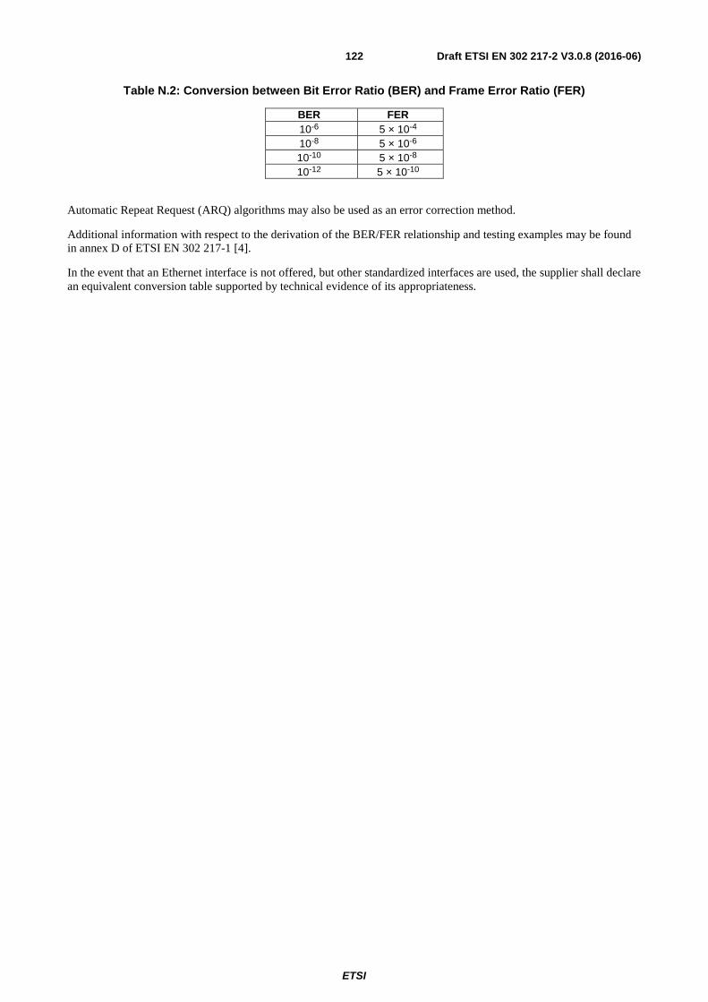
ETSI
Draft ETSI EN 302 217-2 V3.0.8 (2016-06)122
Table N.2: Conversion between Bit Error Ratio (BER) and Frame Error Ratio (FER)
BER FER 10-6 5 × 10⁻⁴ 10-8 5 × 10⁻⁶ 10-10 5 × 10⁻⁸ 10-12 5 × 10⁻¹⁰
Automatic Repeat Request (ARQ) algorithms may also be used as an error correction method.
Additional information with respect to the derivation of the BER/FER relationship and testing examples may be found in annex D of ETSI EN 302 217-1 [4].
In the event that an Ethernet interface is not offered, but other standardized interfaces are used, the supplier shall declare an equivalent conversion table supported by technical evidence of its appropriateness.

ETSI
Draft ETSI EN 302 217-2 V3.0.8 (2016-06)123
Annex O (normative): Test report in relation to flexible systems applications
O.1 Wide radio-frequency band covering units Even if radio frequency front-ends for DFRS are commonly designed for covering all or part(s) of the possible operating channels within a specific radio frequency channel arrangement, equipment can provide single radio frequency channel operation (e.g. when the RF duplexer filters are tuned to a specific channel) or offer a wider operating frequency range (e.g. wide-band RF duplexer and frequency agility through the use of a RFC function. Ease of deployment and spare parts handling by operators with large networks is facilitated where more than one channel is assigned).
The equipment shall comply with all the requirements of the present document at any possible operating frequency.
The tests, carried out to generate the test report and/or declaration of conformity, required to fulfil any conformity assessment procedure with respect to the Directive 2014/53/EU [i.1], shall be carried out in the following way:
1) In the case of equipment intended for single channel operation, within a given channel arrangement, the test report shall be produced for one radio frequency channel arbitrarily chosen by the supplier (see figure O.1).
2) In the case of equipment intended for covering operating frequency sub-ranges (i.e. a number of pre-selectable channels within a given channel arrangement, covered without changing any hardware e.g. duplex filters), it is considered enough that one frequency sub-range is subject of testing. The test report shall be produced:
- For transmitter parameters summarized in table 7, for the lowest (B, bottom), intermediate (M, median) and highest (T, top) possible radio frequency channel within that operating frequency range (see figure O.2).When channels-aggregation (single-band) equipment are concerned this applies to one aggregated channel only; the other aggregated channel shall be tested only at intermediate (M) frequency. In any case, the channel not under test is set as described in the relevant clauses.
- For receiver parameters summarized in table 9, only unwanted emissions in the spurious domain- external and BER as a function of RSL parameters, for the lowest (B, bottom), intermediate (M, median) and highest (T, top) possible radio frequency channel within that operating frequency range. When channels-aggregation (single-band) equipment are concerned this applies to one aggregated channel only; the other aggregated channel shall be tested only at intermediate (M) frequency. In any case, the channel not under test is set as described in the relevant clauses. Other receiver parameters have to be tested for the intermediate radio frequency channel (M) only.
3) It is not required that all the tests, required for the test report, are made on the same sample of equipment and at the same time; provided that the test report includes all of the tests required by the present document, each test may be made on different samples of the same equipment, at different channel frequencies or frequency ranges and at different times (see note).
NOTE: In principle, all tests are carried out on the same equipment during a single test session. However, it is permitted to have different test sessions and equipment under test to allow for unpredictable events (e.g. equipment or test instrument failure during the test session that is not immediately repairable), and for any additional tests required by a future revision of the present document. This allowance is not intended as a means to circumvent failed tests without corrective actions.

ETSI
Draft ETSI EN 302 217-2 V3.0.8 (2016-06)124
When applicable the following additional provisions apply to the production of a test report:
• In the case of equipment covering a radio frequency channel arrangement with more than one operating frequency range, the test report shall be produced for one of the operating frequency ranges arbitrarily chosen by the supplier, using the above procedures for equipment intended for single channel operation or for covering an operating frequency range (see figures O.1 and O.2).
• In the case of equipment designed to cover, with the same requirements under the same ETSI standard, a number of fully or partially overlapping recommended and/or national radio frequency channel arrangements, similarly established across contiguous radio frequency bands allocated to the Fixed Service, the test report shall be produced for one radio frequency channel arrangement arbitrarily chosen by the supplier, using the above procedures for equipment intended for single channel operation or for covering an operating frequency range (see figures O.1 and O.2).
polarizations
1 3 1' 3'H(V)
V(H)
go (return) sub-band return (go) sub-band
CEPT (or ITU-R) Channel
Arrangement (Band A)
National Channel
Arrangement (Band C)
National Channel
Arrangement (Band D)
CEPT (or ITU-R) Channel
Arrangement (Band B)
Test report provision
(arbitrarily chosen)
2 4 N 2' 4' N'
1 3 1' 3'2 4 N 2' 4' N'
Alternative channel
arrangement selection
Contiguous allocated bands with common provisions in only one specific annex of the present document
Figure O.1: Test report frequency requirement for equipment intended for single channel operation

ETSI
Draft ETSI EN 302 217-2 V3.0.8 (2016-06)125
go (return)
sub-band
return (go)
sub-band
CEPT (or ITU-R) Channel Arrangement (Band A)
National Channel Arrangement (Band C)
National Channel Arrangement (Band D)
CEPT (or ITU-R) Channel Arrangement (Band B)
Contiguous allocated bands with common provisions in only one specific annex of the present document
Alternative channel arrangement selection
Low (B)
Central (M)
High (T)
Low = lowest channel in the operating frequency range
High = highest channel in the operating frequency range
Central = Channel nearest to the centre of the operating frequency range
Equipment covering a
sub-band in a single
operating frequency range
Equipment covering a
full band in a single
operating frequency range
Test report
Provision
Equipment covering a
sub-band with multiple
operating frequency ranges
Operating frequency range (arbitrary selection)
Low (B)Central (M)
Low (B) Central (M) High (T)
Figure O.2: Test report frequency requirements for equipment intended for covering an operating frequency range
O.2 Multirate/multiformat equipment
O.2.0 Introduction DFRS equipment can be designed either for a unique payload and modulation format (single-mode systems, see note) or for covering a number of different payload rates ("multirate" systems, see note) or different modulation formats (i.e. different equipment classes) or different error correction codes transmitted, through software presetting or protocols, over a number of different channel separations.
In the latter case, within a certain CS, the payload and modulation presetting may offer static operation over different payload/modulation (preset-mode systems, see note) or dynamic operation changing payload/modulation (mixed-mode systems, see note) according network requirements (e.g. propagation variations).
NOTE: As defined in ETSI EN 302 217-1 [4].
For preset-mode and mixed-mode systems the equipment shall comply with all the requirements of the present document at any possible combination of operating RIC, CS and efficiency classes declared (see note in clause O.2.1).
For channels-aggregation systems each aggregated channel shall comply with all the requirements of the present document (including those related to preset-mode and mixed-mode operation, if implemented) when both emissions are turned on and operating according normal operating conditions within the declared ranges of mutual power and frequency differences (see clause 4.1.1).

ETSI
Draft ETSI EN 302 217-2 V3.0.8 (2016-06)126
O.2.1 Generic required tests in the test report The tests, carried out to generate the test report and/or declaration of conformity, required to fulfil any Conformity assessment procedure with respect to the Directive 2014/53/EU [i.1], shall be carried out, at each frequency channel prescribed in clause O.1, for:
• transmitter parameters summarized in table 7 at any possible CS and efficiency classes, each case should be loaded with the highest possible RIC;
• receiver parameters summarized in table 9 shall be tested only at the lowest and the highest CS for any efficiency class, each case loaded with the highest possible RIC.
Mixed-mode systems, besides specific Dynamic Change of Modulation Order test referred in clause 5.2.6, are to be tested, for each Reference mode offered only (see note), as they were preset-mode systems (i.e. dynamic operation in mixed-mode systems shall be disabled for all other tests).
NOTE: Mixed-mode systems might use a number of modes (e.g. BPSK/4/16/32/64/128/256/512/1024QAM) in dynamic operations but, for technical/operational convenience only few modes might be available as "reference" (e.g. only 4/16/128QAM are considered suitable for network performance and availability needs and/or may find suitable assessment characteristics in the present document); therefore, only the latter ones are relevant for static (preset-mode like) operation conformance test.
Channels aggregation systems, shall be tested as other single emission systems according their mode of operation (i.e. single-mode, mixed-mode or preset-mode).The tests should be made on one of the aggregated channels with the second set in the condition identified in the clause 4.1.1 and clause O.4; this unless clause O.3 conditions apply (i.e. for multi-channel operation realised by a channel-aggregation system).
O.2.2 Reduced set of required tests in the test report
O.2.2.0 Introduction
Preset-mode and mixed-mode systems usually use constant, or scalable with CS, baseband processing (e.g. symbol rate, FEC typology/redundancy). This implies, de facto, that the results of many tests are also expected to have the same results scaled for CS and/or baseband processing.
Therefore, for their test report, Preset-mode and mixed-mode may benefit of a reduced set of required tests as described in following clauses O.2.2.1 and O.2.2.2.
O.2.2.1 Reduced transmitter tests
Further reduction of preset-mode and mixed-mode test report complexity is permitted; transmitter parameters test report may be reduced as follows:
a) The lowest and highest efficiency class provided (preset-mode systems) or used as reference-mode (mixed-mode systems) should be tested, only for the lowest and the highest CS, at all three test frequency channels (B, M and T), if applicable.
b) The other modes provided (preset-mode systems) or used as reference-mode (mixed-mode systems), for the all CSs, only at the M frequency channel. In addition, for these cases, the frequency range of the unwanted emission in the spurious domain test will be reduced to ±1 GHz or to the frequency band boundaries (whichever results larger) across the M test frequency.
In case one or more preset/reference modes may operate on a CS with more than one symbol-rate (e.g. for different error correction coding), the test shall be done with the highest symbol-rate.
Figure O.3 graphically show the reduced set of tests.

ETSI
Draft ETSI EN 302 217-2 V3.0.8 (2016-06)127
CS (MHz)
1 2 3 4L 4H 5L 5H 6L 6H 7 Efficiency class
1,75
~112
3,5
~14
~28
7
~56
Modulation index1 2 3 4 5 6 7 8 9 10
CS and formats considered in the present document
Example of CS/format set provided by a preset/mixed-mode system
TX tests required for one test frequency (M)
TX tests required for three test frequencies (B, M and T)
8
11
Figure O.3: Example of Preset/mixed-mode systems reduced TX test report
O.2.2.2 Reduced receiver tests
As further permitted reduction of preset-mode and mixed-mode test report complexity, it is considered that receiver parameters can be tested, only for efficiency classes provided (preset-mode systems) or used as reference-mode (mixed-mode systems) as follows:
1) RX BER versus RSL (clause 4.3.2):
1a) The lowest and highest efficiency class should be tested, only for the relevant lower and the higher CS, at all three test frequency channels (B, M and T).
2) RX unwanted emissions in the spurious domain (clause 4.3.1) further reduced only to test, at all three test frequency channels(B, M and T), for the lowest and the highest CS with the lowest efficiency class provided for those channels.
3) RX co/adjacent channel interference (clause 4.3.3.2) and CW spurious interference (clause 4.3.3.4) further reduced to test:
3a) At M test frequency channel, with the lowest and highest efficiency class only, for the lowest and the highest CS.
3b) CW spurious interference should be additionally tested also at M test frequency channel with the highest efficiency class only, for other intermediate CSs. In addition, for these cases, the frequency range of the test will be reduced to ±1 GHz or to the frequency band boundaries (whichever results larger) across the M test frequency.
In case one or more preset/reference modes may operate on a CS with more than one symbol-rate (e.g. for different error correction coding), the test shall be done with the highest symbol-rate.
Figure O.4 graphically shows the reduced set of tests.

ETSI
Draft ETSI EN 302 217-2 V3.0.8 (2016-06)128
CS and formats considered in the present documentExample of CS/format set provided by a preset/mixed-mode system
RX tests (BER versus RSL) required for three test frequencies (B, M and T)
RX tests (C/I and CW interference tests required for one test frequencies (M)
RX Spurious emissions tests required for three test frequencies (B, M and T)
CS (MHz)
1 2 3 4L 4H 5L 5H 6L 6H 7 Efficiency class
1,75
~112
3,5
~14
~28
7
~56
Modulation index1 2 3 4 5 6 7 8 9 10
RX CW interference tests required for one test frequency (M) and for reduced frequency range
8
11
Figure O.4: Example of Preset/mixed-mode systems reduced RX test report
O.2.3 Bandwidth adaptive test set requirements When "bandwidth adaptive" operation is considered, the reference modes are defined as those relevant to the widest possible bandwidth and therefore tests for Directive 2014/53/EU [i.1] assessment should be performed according the above clauses O.1 and O.2. There may also be a number of preset operational modes with differing maximum bandwidth; these will be tested as independent CS modes, each with its own "reference modes" (see example).
EXAMPLE: A system may adjust its operational mode to not exceed a maximum licensed CS of 500 MHz, dynamically reducing to 250 MHz or even less (or a maximum licensed CS of 1 000 MHz, dynamically reducing to 250 MHz, and so on). These are seen as two different CS operational modes, 500 MHz and 1 000 MHz.
O.3 BER and C/I measurement in multi-channels systems (including channels-aggregation) when common SDH or Ethernet single/multiple-interfaces payload is provided
O.3.0 Introduction Clause O.3 and its subclauses deal with systems that have both the following characteristics:
• high traffic capacity with common baseband SDH interfaces (e.g. STM-4 or several STM-1), or common baseband Ethernet interfaces (e.g. 1000BaseT or several 100BaseT);
• two combined (through the above common BB interface(s)) emissions, over two different (in frequency and/or polarisation) channels on the same path, using either a "multi-channel" configuration of separate RF equipment or both aggregated-channels of a channels-aggregation equipment (see definition in ETSI EN 302 217-1 [4])). Each channel carrying a half of the total payload.

ETSI
Draft ETSI EN 302 217-2 V3.0.8 (2016-06)129
In order to keep the requirements set out in the standard aligned with single channel single/multiple (e.g. N × 2 Mbit/s) interface(s), there is a need to modify the basic requirements definition according to the system type. BER and C/I performance measurements and test setup need to take into consideration the system type and configuration. The purpose of this annex is to provide guidance for the measurement of these systems.
NOTE: In addition, without any impact on the guidelines of this annex, the emission on each channel could be composed by one single-carrier or by two or more sub-carriers ("multi-carrier" equipment, see definition in ETSI EN 302 217-1 [4]).
O.3.1 Case 1: multi-interfaces/two-channels systems where each interface payload is transmitted on one channel only
This case is also equivalent to generic single-channel equipment (or generic channels-aggregation equipment) operation (see note); therefore, the test procedure falls in the general case described in the main body of the present document.
NOTE: The difference may reside in a baseband unit common to both channels; which is irrelevant from the radio performance point of view when no traffic interface split its data over the two channels.
This case fits with the examples of transmission of 2 × STM-1 (or 3 × 100BaseT) single channel and 4 × STM-1 (or 6 × 100BaseT) dual channels; each interface is transmitted only over one channel.
Test equipment will be connected to one of the STM-1 or 100BaseT interfaces (as in the single-channel general case). The resulting BER shall comply with the requirements in the standard.
Since each STM-1 (or 100BaseT) signal is transmitted by one equipment on one single channel (or one of the aggregated channels), all measurements of performance are in general identical to other single interface, single channel (or one of the aggregated channels) operation.
O.3.2 Case 2: single interface or multi-interfaces/two-channels system where each payload interface is transmitted equally split on both channels
This case fits with the example of transmission of STM-4 (or 1000BaseT) dual channels or fits with the examples of transmission of 4 × STM-1 (or 6 × 100BaseT) dual channels; each STM-1 or 100BaseT interface is transmitted, equally split (see note), over both channels.
NOTE: For Ethernet transmission, the equally split condition is for testing purpose only; it is assumed that when in operation, the split can be dynamically assigned according path conditions and/or traffic priority.
Test equipment will be connected to one interface only, e.g. the STM-4 or one STM-1 (or 1000BaseT or one 100BaseT) interface. The resulting BER shall comply with the requirements in the standard as described in table O.1.
If dynamic traffic split is implemented, it should be blocked to a fixed 1/2 split.

ETSI
Draft ETSI EN 302 217-2 V3.0.8 (2016-06)130
Table O.1: BER for single interface/two channels system
Clause Measurement Test method (see note 1) BER requirement
4.3.2 BER vs. RSL
Multi-channel: Both channels Simultaneously (same RSL). The attenuation is simultaneously increased until the RSL thresholds, as specified in clause 4.3.2, are reached (see note 2)
As specified
Channels-aggregation/single-port: Common simulated link on both channels (TX powers shall be balanced for same RSL) spaced on 2nd adjacent. The attenuation is simultaneously increased until the RSL threshold, as specified in clause 4.3.2, is reached on both channels. Channels-aggregation/dual-port: Separate simulated link added to each channels (same RSL shall be obtained) placed on 1st adjacent operation (see note 3). The attenuation is simultaneously increased until the RSL threshold, as specified in clause 4.3.2, is reached on both channels.
4.3.3.2 Co-channel "external" and adjacent channel Interference
Relative channel frequencies and simulated links arrangement as above for each type of system. The same simulated link(s) attenuation should be added to both channels until the same 10-6 RSL threshold, as specified in clause 4.3.2, is reached. The interferer and the 1 dB (3 dB) degradation (see note 4) is applied to one channel only
As specified (see note 4)
4.3.3.3 (method 1)
CW spurious interference
Relative channel frequencies and simulated links arrangement as above for each type of system. The same simulated link(s) attenuation should be added to both channels until the same 10-6 RSL threshold, as specified in clause 4.3.2, is reached. The interferer and the 1 dB degradation (see note 4) is applied to one channel only. The CW interference is applied in the specified frequency range (see note 6).
As specified (see note 4)
4.3.3.3 (method 2)
CW spurious interference
Relative channel frequencies and simulated links arrangement as above for each type of system. The same simulated link(s) attenuation should be added to both channels until the same 10-6 RSL threshold, as specified in clause 4.3.2, is reached. The interferer is applied to one channel only. The CW interference is applied in the specified frequency range (see note 6).
As specified (see note 5)
NOTE 1: Test frequencies (B, M and T, as required by table 9) apply to one of the two channels, unless when channels-aggregation (dual-band) operation is considered (separate band assessment is required). Also, the required 1st or 2nd adjacent channels placement may not be applicable (e.g. for dual-band operation); in this case the closest possible frequency shall be used.
NOTE 2: Relative frequencies and simulated link arrangement (common or separate) chosen by the supplier. NOTE 3: (informative) 1st adjacent channel operation is foreseen with no degradation permitted because the separate
simulated links do not generate actual interference for the two channels. NOTE 4: In some cases, it is not possible to apply the 1 dB / 3 dB RSL increase only to the channel under test (e.g. in
common simulated link e.g. for channels-aggregation/single-port, it is impossible to increase RSL power only on the channel under test). In this case the BER requirement shall be halved (i.e. BER ≤ 5 × 10⁻⁷ valid in all cases save for method 1 of clause 4.3.3.3).
NOTE 5: When method 2 of clause 4.3.3.3 is used for channels-aggregation/single-port, the CW interference applied to one aggregated-channel only implies that the requirement is halved i.e. BER ≤ 5 × 10⁻⁶ instead of ≤ 5 × 10⁻⁵.
NOTE 6: The single CW interference applied for single-port equipment shall exclude frequencies either side of both aggregated channels frequency by up to 250 %.

ETSI
Draft ETSI EN 302 217-2 V3.0.8 (2016-06)131
O.4 Test provisions for channels-aggregation equipment
O.4.1 General requirements and test method Channels-aggregation equipment needs additional consideration for ensuring that the two aggregated channels do not interfere each other in the internal TX and RX signal paths so that no impairment of the single-channel requirement is present.
Therefore spectrum mask and unwanted emission in the spurious domain tests shall be carried as described in table O.2.
Table O.2: Channels-aggregation equipment spectral mask and unwanted emission in the spurious domain
Clause Measurement Test method Compliance Requirement
4.2.4 Spectral Mask
Both channels on: adjacent tuning (see note 4):
Single-port
Dual-ports
- Combination of two spectral masks. See
figure O.5 and clause O.4.2 (see notes 2 and 5)
- Normal mask for both channels (see note 2)
4.2.4 Spectral Mask
Both channels on: farthest tuning Single-port
Dual-ports
- Sum of two spectral masks. See figure O.6
(see notes 3 and 5) - Normal mask for both channels
(see note 3)
4.2.4 Spectral Mask One channel on, second off and vice versa (2 tests) Single-port
Spectral mask according to 4.2.4.2.1 (conditional test see note 1)
4.2.6 unwanted emission in the spurious domain
Both channels on: farthest tuning Single-port Dual-ports
- Combined limit: see figure O.8 (see note 3) - Normal Limits for both channels (see note 3)
4.2.6 unwanted emission in the spurious domain
One channel is on, while other channel is off (2 tests) Single-port
As specified (conditional test see note 1)
NOTE 1: Additional tests only for single-port case, only if needed for combined limit in clause O.4.2. One channel is tested for B, and/or M and/or T frequencies as needed.
NOTE 2: For single-band operation, one channel is tested for B, M and T frequencies, with other channel as convenient (i.e. upper for B test, lower for H test, indifferent for M test. For dual-band operation separate B, M and T tests for both channels.
NOTE 3: For single-band operation, one channel is tested for B, M and T frequencies, with other channel set at farthest possible frequency. For dual-band operation separate B, M and T tests for both channels.
NOTE 4: Test not required for dual-band operation. NOTE 5: Combined limits relaxation according clause O.4 and figures O.7 and O.8 shall apply as well when relevant.

ETSI
Draft ETSI EN 302 217-2 V3.0.8 (2016-06)132
Figure O.5: Channels-aggregation equipment: combined adjacent channels spectral mask
a) b)
NOTE: It should be highlighted that the blanc space in the middle of the two emissions (i.e. spurious domain for both in figure b) is present only when the spacing between the emission is higher than 5 × CS. Therefore, in a number of cases, it will not be experienced and figure a) example (here 4 × CS case) applies.
Figure O.6: Channels-aggregation equipment: farthest channels spectral mask
-55
-50
-45
-40
-35
-30
-25
-20
-15
-10
-5
0
5
-90 -70 -50 -30 -10 10 30 50 70 90 110
dBr
1st Channel 2nd (adjacent) Channel Channels-aggregation mask
-60
-50
-40
-30
-20
-10
0
10
-80 -60 -40 -20 0 20 40 60 80 100 120 140 160 180 200
dBr
1st Channel 2nd (not adj) Channel Channels-aggregation mask
-55
-50
-45
-40
-35
-30
-25
-20
-15
-10
-5
0
5
-90 -70 -50 -30 -10 10 30 50 70 90 110 130 150 170 190 210 230 250 270 290
dBr
1st Channel 2nd (not adj) Channel Channels-aggregation mask

ETSI
Draft ETSI EN 302 217-2 V3.0.8 (2016-06)133
O.4.2 Limits combination for single-port case For channels-aggregation systems, each aggregate channel emission shall be compliant when the other channel emissions is turned off or also turned on in any possible frequency and/or polarisation within their permitted setting range.
When the single-port case equipment is concerned, the overall emission is the power combination of the two emissions, both separately fulfilling the required limit; therefore, in frequencies where either the spectrum masks or the spurious domains limits are possibly exceeded, the combined emission limit may be accordingly scaled as follows:
1) In frequency ranges where homogeneous limits apply for both aggregated channels; i.e. in masks crossover central to frequency range (C) in figure O.7 and figure O.8a or in the spurious domain frequency ranges (A) of figures O.7 and O.8a and O.8b:
1.1 When discrete CW spectral lines are concerned, the same limit applies.
1.2 When spread spectral densities are concerned the limit may be relaxed on the basis of the actual emissions levels of the individual aggregated channel emissions, when second channel is turned off, according the following formula:
⎥⎥⎦
⎤
⎢⎢⎣
⎡
⎟⎟⎠
⎞⎜⎜⎝
⎛+= 0 , 1010log10Max (dB) Relaxationn Combinatio 10
M
10
M 21
(0.1)
where M1 and M2 are the margins (-dB) to the relevant limit that each aggregated channel emissions have separately shown when the second is turned off (see example 1).
EXAMPLE 1: With second channel turned off, at certain spurious domain frequency under test, the emission on aggregate channel 1 had 1 dB margin (M1 = −1) on the limit of -50 dBm/MHz, while the emission on aggregate channel 2 had 3 dB margin (M2 = −3) on that limit. When both are turned on, at that spurious domain frequency, the limit is relaxed by 1,12 dB.
2) In the frequency ranges where inhomogeneous limits apply for each aggregated channel; i.e. in frequency ranges (B) of figures O.6 and O.7, the spectrum mask for one aggregated channel overlaps the spurious domain for the other. In this case, the relative spectral emission density of the mask shall be first normalised into absolute power density in dBm/MHz (rightmost axe in the example figures O.6 and O.7) for comparison to the unwanted emission in the spurious domain levels (see note). Then the following apply:
2.1 When discrete CW spectral lines are concerned, the unwanted emission in the spurious domain of one channel can exceed the mask limit of the other and vice versa (see note 2);
2.2 When spread spectral densities are concerned the combined margin of (see equation O.1) above still apply considering that M1 is the margin (-dB) of one channel to its own relevant limit (e.g. spectrum mask or spurious domain) while M2 is the inhomogeneous difference (case by case +dB or -dB, see note 1) between the first channel limit and the second channel emission in that frequency (e.g. spectrum mask "limit" minus spurious domain "actual emission" or vice versa, see examples 2 and 3 and note 3).
NOTE 1: Unless difficult calibration of the test setup is carried on, for conventional QAM formats the normalisation may be made translating the 0 dB reference of the spectrum mask into a power reference of [Pout − 10log (Symbol frequency)] dBm/MHz. Depending on the frequency band and system parameters, the spurious domain emission limit (e.g. −50 dBm/MHz or −30 dBm/MHz) may result higher or lower than the spectrum mask limits (e.g. in the specific example of figures O.6 and O.7 the -30 dBm/MHz spurious domain limit is higher than the spectrum mask).
NOTE 2: The level of the CW spectral lines does not benefit of any relaxation because can be verified with very narrow resolution bandwidth not affected by additional spectral density power.
NOTE 3: It is intended that the relaxation of the spectrum mask could be further verified with a resolution bandwidth coherent with the spurious limit (e.g. of 1 MHz above 1 GHz as in the most common examples 2 and 3) independently from the actual value prescribed in table 8 for the system under consideration. Alternatively the spurious emission level should be normalised to the mask resolution bandwidth and similar calculation be done.

ETSI
Draft ETSI EN 302 217-2 V3.0.8 (2016-06)134
EXAMPLE 2: With reference to figure O.7 lower frequency B range: 1) Possible relaxation of the spectrum mask of blue channel: with second (e.g. red one at the higher frequency) channel turned off, at certain spectrum mask frequency within lower (B) range under test, the emission on first (i.e. the blue one at lower frequency) aggregate channel had 1 dB margin (M1 = −1) on its mask limit of −50 dBr (level that have been verified to correspond to an absolute power density of −41 dBm/MHz), while the spurious emission of second aggregate channel (i.e. the red one with other blue channel turned off) has a level (derived from the spurious domain emission test) of −38 dBm/MHz (i.e. exceeds 3 dB the mask limit normalised to absolute power density, M2 = 3). When both are turned on, at that mask frequency, the mask limit is relaxed by 4,45 dB. 2) Possible relaxation of the spurious level of red channel: Following the same rationale, the spurious emission limit of the red channel, in correspondence of the −38 dBm/MHz spectral emission (M1 = −8) could not be further relaxed because the combination, through equation O.1 above, of the blue mask power of −42 dBm/MHz (M2 = −12 with respect to the spurious limit of −30 dBm/MHz) results in a negative −6,54 dB value, and therefore according to (see equation O.1) Combination Relaxation will be 0 dB (total of: −30 dBm/MHz).
EXAMPLE 3: With reference to figure O.7 upper frequency B range: 1) Possible relaxation of the spectrum mask of red channel: with previous (e.g. the blue one at lower frequency) channel turned off, at certain spectrum mask frequency within upper (B) range under test, the emission of the blue aggregate channel had 2 dB margin (M1 = −2) on its mask limit of −50 dBr (level that also corresponds to an absolute power density of −41 dBm/MHz), while the spurious emission of other aggregate channel (i.e. the blue one with red channel turned off) has a level (derived from the spurious domain emission test) of exactly −30 dBm/MHz (i.e. exceeds 11 dB the mask limit normalised to absolute power density, M2 = 11). When both are turned on, at that mask frequency, the mask limit is relaxed by 11,21 dB. 2) Possible relaxation of the spurious level of blue channel: Following the same rationale, the spurious emission limit of the blue channel, in correspondence of the −30 dBm/MHz spectral line (M1 = 0) could be further relaxed because the combination, through equation O.1 above, of the red mask power of −43 dBm/MHz (M2 = −13 with respect to the spurious limit of −30 dBm/MHz) results in a positive 0,21 dB.

ETSI
Draft ETSI EN 302 217-2 V3.0.8 (2016-06)135
Figure O.7: Example of combined limits in adjacent channels conditions (23 GHz to 28 GHz band; class 4H; Pout = +23 dBm; symbol frequency 25 MHz)
a) b)
NOTE: Example a) refers to the case up to 4 × CS emission spacing; example b) refers to cases with emission spacing > 5 × CS. In 5 × CS spacing case neither range (C) nor range (A) are present in between the two emissions.
Figure O.8: Examples of combined limits in farthest channels conditions
(23 GHz to 28 GHz band; class 4H; Pout = +23 dBm; symbol frequency 25 MHz)
-46
-41
-36
-31
-26
-21
-16
-11
-6
-1
4
9
14
-55
-50
-45
-40
-35
-30
-25
-20
-15
-10
-5
0
5
-90 -70 -50 -30 -10 10 30 50 70 90 110
dBm/MHz
dBr
1st Channel 2nd(adjacent) Channel Multi-emission mask Spurious Domain Limit
-(A) ----><-----(B) ------><-----------------------------------(C) --- ------------------------------><-----(B) ------> <--(A)--
-43
-33
-23
-13
-3
7
17
-55
-45
-35
-25
-15
-5
5
-80 -60 -40 -20 0 20 40 60 80 100 120 140 160 180 200
dBm/MHz
dBr
1st Channel 2nd (not adj) Channel
Channels-aggregation mask Spurious domain limit
-(A)--> <----------------------- (B) ----------------------><----(C) ---> <----------------------(B) -------------------------><--(A)---46
-41
-36
-31
-26
-21
-16
-11
-6
-1
4
9
14
-55
-50
-45
-40
-35
-30
-25
-20
-15
-10
-5
0
5
-90 -70 -50 -30 -10 10 30 50 70 90 110 130 150 170 190 210 230 250 270 290
dBm/MHz
dBr
1st Channel 2nd (not adj) Channel Multi-emission mask Spurious Domain limit
-(A)--> <------------------- (B) ----------------------><-----(A) -----> <----------------------(B) ---------------------><--(A)--
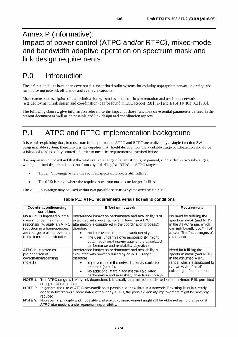
ETSI
Draft ETSI EN 302 217-2 V3.0.8 (2016-06)136
Annex P (informative): Impact of power control (ATPC and/or RTPC), mixed-mode and bandwidth adaptive operation on spectrum mask and link design requirements
P.0 Introduction These functionalities have been developed in most fixed radio systems for assisting appropriate network planning and for improving network efficiency and available capacity.
More extensive description of the technical background behind their implementation and use in the network (e.g. deployment, link design and coordination) can be found in ECC Report 198 [i.27] and ETSI TR 103 103 [i.35].
The following clauses, give information relevant to the impact of those functions on essential parameters defined in the present document as well as on possible and link design and coordination aspects.
P.1 ATPC and RTPC implementation background It is worth explaining that, in most practical applications, ATPC and RTPC are realized by a single function SW programmable system; therefore it is the supplier that should declare how the available range of attenuation should be subdivided (and possibly limited) in order to meet the requirements described below.
It is important to understand that the total available range of attenuation is, in general, subdivided in two sub-ranges, which, in principle, are independent from any "labelling" as RTPC or ATPC ranges:
• "Initial" Sub-range where the required spectrum mask is still fulfilled.
• "Final" Sub-range where the required spectrum mask is no longer fulfilled.
The ATPC sub-range may be used within two possible scenarios synthesized by table P.1.
Table P.1: ATPC requirements versus licensing conditions
Coordination/licensing conditions
Effect on network Requirement
No ATPC is imposed but the user(s), under his (their) responsibility, apply an ATPC reduction in a homogeneous area for general improvement of the interference situation.
Interference impact on performance and availability is still evaluated with power at nominal level (no ATPC attenuation is considered in the coordination process); therefore:
• No improvement in the network density. • The user, under his own responsibility, might
obtain additional margin against the calculated performance and availability objectives.
No need for fulfilling the spectrum mask (and NFD) in the ATPC range, which can indifferently use "initial" and/or "final" sub-ranges of attenuation.
ATPC is imposed as pre-condition of coordination/licensing (note 1)
Interference impact on performance and availability is evaluated with power reduced by an ATPC range; therefore:
• Improvement in the network density could be obtained (note 2).
• No additional margin against the calculated performance and availability objectives (note 3).
Need for fulfilling the spectrum mask (and NFD) in the assumed ATPC range, which is supposed to remain within "initial" sub-range of attenuation.
NOTE 1: The ATPC range is link-by-link dependent, it is usually determined in order to fix the maximum RSL permitted during unfaded periods.
NOTE 2: In general the use of ATPC pre-condition is possible for new links in a network; if existing links in already dense networks were coordinated without any ATPC, the possible density improvement might be severely reduced.
NOTE 3: However, in principle and if possible and practical, improvement might still be obtained using the residual ATPC attenuation, under operator responsibility.

ETSI
Draft ETSI EN 302 217-2 V3.0.8 (2016-06)137
Therefore, from the point of view of equipment use in the network, the RTPC and ATPC "labelling" of the available attenuation range is, in principle, different for the two cases considered in table P.1; figure P.1 summarizes this aspect (see note).
NOTE: The use of ATPC in the license conditions is foreseen in some countries on national basis; in addition, the implementation of ATPC functionality is left, as an option, to manufacturer choice. Therefore, the ATPC assessment for specific licensing conditions is not retained "essential" for Directive 2014/53/EU [i.1] point of view. Nevertheless, the supplier is recommended to define the RTPC/ATPC ranges possibly available for that purpose.
Tota
l ran
ge o
f po
wer
con
trol
Max
imum
ran
ge o
f po
wer
con
trol
fu
lfill
ing
the
spec
trum
mas
k(“
Init
ial”
sub
-ran
ge) RTPC/ATPC range subdivision
(possibly depending on RTPC need for obtaining the licensed e.i.r.p.)
Ran
ge u
sabl
e fo
r R
TP
C a
nd/o
r A
TP
C(u
nder
use
r re
spon
sibi
lity)
Ran
ge u
sabl
e fo
r A
TP
C o
nly
(und
er u
ser
resp
onsi
bilit
y)
Ran
ge o
f po
wer
con
trol
not
fu
lfill
ing
the
spec
trum
mas
k(“
Fin
al”
sub-
rang
e)
Maximum nominal power
Minimum power
Max
imum
ran
ge u
sabl
e fo
r A
TP
C
(use
able
for
licen
sing
con
diti
ons)
Shor
ter
hops
red
uced
AT
PC
ran
ge (
usea
ble
for
licen
sing
con
diti
ons)
Shor
ter
hops
R
TP
C r
ange
Technical limitations
Limitations when ATPC is not used as licensing/coordination condition
(ATPC may still be used only under user responsibility for improving its own network density)
Limitations whenATPC is used as
licensing/coordination condition
Ran
ge u
sabl
e fo
r fu
rthe
r A
TP
C r
ange
(u
nder
use
r re
spon
sibi
lity)
Figure P.1: ATPC/RTPC ranges and licensing/coordination conditions
P.2 Mixed-mode operation impact
P.2.1 Basic concepts Mixed-mode systems (see note) can dynamically (on the basis of RSL and other built-in quality parameters) smoothly switch between different modulation formats, increasing/decreasing the payload capacity accordingly. At the same time they can manage the TX power output, reducing it for the higher complexity formats that require higher linearity. Therefore, mixed-mode systems have also a built-in ATPC functionality.
NOTE: Mixed-mode is a notation used in the present document, for commonality with similar concept previously defined for P-MP systems in ETSI EN 302 326-2 [i.28]. However, in common point-to-point market practice, these systems are more often identified as "adaptive coding and modulation" (ACM) systems.

ETSI
Draft ETSI EN 302 217-2 V3.0.8 (2016-06)138
Mixed-mode technology might be combined with variable (more or less redundant) coding techniques for the same format. In addition, further bandwidth adaptive functionality could, in principle, be used (e.g. after reaching the simplest modulation format, the system bandwidth is reduced as described in clause P.3) for further enhancing the link availability for a very limited portion of payload (beyond the minimum modulation format). However; the possible use of this feature is irrelevant for the technical descriptions in this clause.
The variable capacity of the mixed-mode systems in various propagation conditions implies that part of the maximum payload is gradually lost. This also requires that mechanism for defining different priority steps to portion of the payloads should be provided and the mixed-mode system should be able to detect it in order to gradually eliminate lower priority parts.
P.3 Bandwidth adaptive operation impact
P.3.1 Basic concepts Bandwidth adaptive systems can dynamically (on the basis of RSL and other built-in quality parameters) smoothly switch between different bandwidth with the same modulation formats, increasing/decreasing the payload capacity accordingly. In principle, the output power is kept constant because no different linearity requirements are present; therefore, differently from mixed-mode ACM systems, bandwidth adaptive systems might not have ATPC built-in functions.
These systems are mainly used for high capacity systems in EHF bands (e.g. 70 GHz and 80 GHz) where the radio frequency technology does not (yet) permit:
• The use of high level modulation formats (simplest 2 or 4 levels could only be practical until enhanced radio frequency technology might become popular).
• Enough TX power and RX sensitivity for producing a sufficient fade margin for operating the maximum capacity on relatively long hops in geographical areas with sensible rain-rate.
In principle, this technology might be combined with Mixed-mode functionality (e.g. switching also between PSK and QPSK). Still in principle, this technology might also be added to (full) (ACM) systems described in clause P.2 for further enhancing the link availability for a very limited portion of payload (beyond the minimum modulation format).
P.3.2 Bandwidth (channel) occupancy When operated in a network requiring coordination (either under administration or user responsibility) the occupied bandwidth or the channel occupancy (when a channel arrangement is provided) and their relevant system characteristics for coordination (Reference mode) should be defined for the maximum bandwidth that will be used for the link under consideration.
P.4 Impact on frequency co-ordination The possible operative conditions described in detail in ECC Report 198 [i.27] and ETSI TR 103 103 [i.35], in general implies from time to time the change of modulation format, TX output power and bandwidth. Applied on link by link frequency coordinated bands, the above documents consider the implications deriving from the licensed use of the spectrum.

ETSI
Draft ETSI EN 302 217-2 V3.0.8 (2016-06)139
P.5 Impact on article 3.2 "essential" parameters and operating conditions
From the discussion in previous clauses, for being capable of responding to the above mentioned licensing constraints, the introduction of mixed-mode (adaptive) systems within the frame of the present document needed a specific set of parameters related to Directive 2014/53/EU [i.1] article 3.2 "essential requirements".
These requirements may be summarized as follows:
1) As for any multirate/multiformat equipment, in the scope of the present document, mixed-mode systems should demonstrate of being capable of respecting all requirements for each of the rate/format offered (i.e. mixed-mode systems are tested as preset-mode systems). In this way it is ensured that the any selected "Reference mode" (equipment class) can be singularly satisfied (see note).
2) A specific set of presetting in term of matching payload capacity, modulation format and transmit power (including RTPC/ATPC operations, see also note in clause P.1) has to be defined and assessed so that, within a licensed constant channel bandwidth and whichever is the instantaneously used mode (format), the TX spectrum mask, will not exceed that of the "Reference-mode" equipment class, as defined in the present document, among any possibly declared ones (which will be used for the link-by-link frequency coordination/licensing process) (see note).
3) Ensure that requirement 2) above is respected also during dynamic transitions between different modes. A specific requirement and conformance test has been introduced.
4) Bandwidth adaptive systems should be capable of respecting all requirements for the corresponding maximum bandwidth, which will define the "reference mode" (or multiple "reference modes" when more than one basic licensed channel size may be "pre-set" by the equipment.
NOTE: According requirement 2), mixed-mode systems, when in operation, do not need to meet all spectrum mask requirements in 1), which are tested for Directive 2014/53/EU [i.1] article 3.2 conformance purpose only; from the technical co-ordination point of view, only that of the "Reference-mode" equipment class should be respected. Licensing fees, possibly related to system capacity, are not in the scope of the present document, but are responsibility of national administrations.

ETSI
Draft ETSI EN 302 217-2 V3.0.8 (2016-06)140
CoCh/AdCh interf 4 QAM referenceCoCh/AdCh interf 16 QAM
Noise floor
N+I (I operating at 4 QAM reference)~1 dB
S/(N+I)4
4 QAM Threshold(including any “I”)
16 QAM Threshold(including any “I”)
16 Q
AM
Fad
e M
argi
n (<
ref
eren
ce)
4 Q
AM
Fad
e M
argi
n (r
efer
ence
)
S/(N+I)16
16 QAM power
4 QAM power (reference)4 to 16 QAM Back-off (if necessary)
+ linearity (if necessary)
N+I (I at 16 QAM<4QAM ref)
4 QAM Mask (Ref. Format)
Higher modulation formats power
Higher QAM Threshold(including any “I”)
Hig
her
QA
M F
ade
Mar
gin
(<<
ref
eren
ce)
Wanted TX
behaviour
Wanted RX
thresholds behaviour
Interfering system (4QAM reference)
behaviour
Figure P.2: Example of nodal co-channel interference (reference modulation format 4QAM):
Delta Fade Margin (dB) = Delta Thr + Back-off
CoCh/AdCh interf: 4 QAM = 16 QAM reference
Noise floorN+I (I 4 QAM = I 16 QAM reference)~1 dB
S/(N+I)4
4 QAM Threshold (including any “I”)
16 QAM Threshold (reference)(including any “I”)
16 Q
AM
Fad
e M
argi
n (r
efer
ence
)
4 Q
AM
Fad
e M
argi
n (>
ref
eren
ce)
S/(N+I)16
16 QAM power (reference) = 4 QAM power
linearity unchanged: NFD 4 = NFD 16 QAM
16 QAM Mask (Ref. Format)
Higher modulation formats power
Higher QAM Threshold(including any “I”)
Hig
her
QA
M F
ade
Mar
gin
(< r
efer
ence
)
Wanted TX
behaviour
Wanted RX
thresholds behaviour
Interfering system (16QAM reference) behaviour
Figure P.3: Example of nodal co-channel interference (reference modulation format 16QAM):
Delta Fade Margin 4/16 = Delta Thr Delta Fade Margin 16/Higher QAM = Delta Thr + Back-off

ETSI
Draft ETSI EN 302 217-2 V3.0.8 (2016-06)141
Annex Q (informative): Typical interference sensitivity behaviour for frequency planning purpose In annexes B to J, for conformity assessment and declaration, the requirements for co-channel and adjacent channel(s) are limited to discrete guaranteed points at 1 dB and 3 dB degradation of the RSL for BER ≤ 10-6.
Figure Q.1 shows the typical behaviour for intermediate points which can be used for frequency planning purpose. Two different plots are given that are dependent on the difference between 1 dB and 3 dB RSL degradation.
Figure Q.1: Interference threshold degradation versus C/I (typical behaviour)
Systems with 3 dB difference between 1 dB and 3 dB RSL
degradation
X+1 dB
X+3 dB
C/I referred at point B or C (dB)
Receiver Input Level at Reference Point B or C relative to BER ≤ 10-6 threshold (X dBm)
BER ≤10-6
Y = C/I for 1 dB RSL
degradation
X dBm
C/I for 3 dB RSL
degradation
Y dB Y+3 dB Y+4 dB Y+2 dB Y+1 dB Y-1 dB Y+5 dB
Systems with 4 dB difference between 1 dB and 3 dB RSL
degradation

ETSI
Draft ETSI EN 302 217-2 V3.0.8 (2016-06)142
Annex R (informative): Technical background for receiver selectivity and C/I interference sensitivity evaluation
R.1 Receiver selectivity
R.1.1 Introduction In general the term selectivity indicates the transfer function in terms of gain (or attenuation) versus frequency of a given double bipole.
When the bipole comprises several complex and active functions the transfer function is a combination of many elementary parts; the presence of active functions also implies that the total transfer function depends also on the levels of the signals passing through (e.g. due to non linear effects).
In digital microwave receivers the input and output signals are inhomogeneous (RF modulated signal input and digital data stream output); therefore, a plain gain/frequency transfer function cannot be practically defined or tested. In addition, the signal environment is generally "broadband"; therefore, single frequency selectivity values are not practically enough for devising wide band RX response to wide band interference (i.e. wide band integration is necessary).
Furthermore, the digital implementation of filters, typically employed for the final baseband channel shaping, implies that their predicted performance are experienced only in presence of like-modulated interfering signals. For interfering signals of different nature the response, while performances are still close, they cannot be assumed the same; therefore, the use of CW line becomes appropriate and convenient for interfering signals far from the wanted centre frequency where the analogue parts of filter chain (typically at RF and IF level) become more predominant. Here the CW line interference becomes quite representative for any kind of interfering signal, including broadband ones, e.g. for compatibility with service/systems allocated in adjacent bands.
For the above reasons, DFRS receiver selectivity is generally described and easily tested through BER threshold degradation in presence of interference at predefined frequency offset and C/I ratio. Comparing the C/I ratios at given BER threshold degradation to the co-channel C/I ratio producing the same degradation it is possible to estimate the overall (broadband) selectivity of the receiver to like signals at various distance from RX centre frequency. This kind of wide-band selectivity (WBSEL) response is comprehensive of all effects (linear and not linear) that define the overall response of the receiver to interference; therefore, it is intended as the real selectivity of the digital receiver.
The WBSEL mask can be easily evaluated through the assessments provided for:
• co-channel interference sensitivity C/I at 1 dB threshold degradation (C/IC) required in clause 4.3.3.2.2;
• first adjacent channel interference sensitivity C/I at 1 dB threshold degradation (C/I1A) required in clause 4.3.3.2.2;
• second adjacent channel interference sensitivity C/I at 1 dB threshold degradation (C/I2A) required in clause 4.3.3.2.3;
• CW spurious interference C/I at 1 dB threshold degradation (C/ICW); test required in clause 4.3.3.3 at any frequency over a wide frequency range (i.e. continuous sweep) starting from the spurious domain boundary.
It should be reminded that the first three requirements are "wideband" interference related, while the third is CW "single line" interference; therefore, the WBSEL, can be intended "guaranteed" from 2014/53/EU [i.1] point of view only in the assessed frequencies and under their specific assessment provisions (i.e. like-modulated or CW C/I ratio); nevertheless, it can be usefully used for any sharing/compatibility study with service/system other than DFRS.

ETSI
Draft ETSI EN 302 217-2 V3.0.8 (2016-06)143
R.1.2 Graphical representation of WBSEL From the above background it is possible to derive the WBSEL in graphical form as shown in figure R.1.
The graph in figure R.1 is usually used as response to a "broadband" interference, i.e. with bandwidth comparable to that of the concerned DFRS; therefore, the point derived from CW line interference in clause 4.3.3.3 is considered applicable, in such broadband context, from the 3rd CS spacing on.
NOTE 1: It is commonly assumed that, at 0,5 × CS, 3 dB of WBSEL is obtained. NOTE 2: WBSEL1A point evaluated as C/IC− C/I1A requirements in clause 4.3.3.2.2. NOTE 3: WBSEL2A point evaluated as C/IC− C/I2A; it depends on the level of compliance and manufacturer declaration
requirements in clause 4.3.3.2.3 (see background in clause R.2 below) NOTE 4: WBSELCW range evaluated as C/IC− C/ICW; requirement in clause 4.3.3.3; value is valid from ± 3rd CS (as
centre frequency of the channel fully within the CW requirement range) and up to the frequency range where the CW test is defined by ETSI EN 301 390 [3]. It should also be understood that WBSELCW value is applicable on real interference environment only if the interfering signal emission exhibits a corresponding reduction of its OOB and spurious emissions within the victim DFRS RX bandwidth.
Figure R.1: wide-band integral selectivity (WBSEL) graphical representation
Table R.1 shows the WBSEL corner points evaluated for few example systems in the present document.
Table R.1: Examples of WBSEL corner points (ref. to figure R.3) calculated from C/I requirements
Reference Index Class Band (GHz) CS (MHz) WBSEL1A (dB) WBSEL2A (dB) WBSELCW >3A (dB)
4 4L 13 < 56 31 31 to 50,9 60
56, 112 34 34 to 50,9 59 8 6L/6LB 23 ÷ 28 All 40 40 to 49,2 70 6 5LB > 57 250, 500 33,5 33,5 to 44,3 63,5 4 4L > 57 1250 27 27 to 32,5 57
R.2 C/I interference sensitivity
R.2.1 Introduction The interference sensitivity behaviour of a digital receiver mainly depends on four factors:
1) The modulation format and the error corrections algorithms; basically defining the co-channel C/I behaviour.

ETSI
Draft ETSI EN 302 217-2 V3.0.8 (2016-06)144
2) The spectrum mask of the interfering signal; basically defining the residual of the interfering signal falling within the victim receiver bandwidth. This would limit the best obtainable behaviour of the receiver in presence of such interference.
3) The ideal receiver filters chain transfer function; basically defining the capability of the receiver of reducing interference level at various frequency distance from the victim receiver centre frequency.
4) The level of C/I ratio at each intermediate stage of the receiver chain; basically related to the possible non linear effects when the interference I is significantly larger than the wanted signal C.
On the basis of the above factors, the following background is relevant for each of the C/I interference sensitivity requirements in the present document:
a) Co-channel C/Ico ratio is related to the S/N ratio (e.g. for BER = 10-6) typical for the actual modulation format. It can slightly differ due to the error correction employed, but is substantially a constant for each format (see note).
b) First adjacent channel C/I1A ratio mainly depends on the pulse "shaping" (roll-off) filters (typically obtained by baseband digital filters in TX and RX chains) that determine the 1st adjacent NFD. In minor extent, it also depends on 3rd order intermodulation effects of the interfering TX (generally controlled by TX spectrum mask, see note). It should be noted that the TX "shaping" part is only marginally controlled by the spectrum mask, which, being made by discrete segments, cannot closely describe a continuous shaping. First adjacent channel C/I ratio typical requirement in DFRS applications is generally limited to about 0 dB to -5 dB; this implies that in no stage of the RX chain non linear effects (point 4 above) are expected.
Second adjacent channel C/I2A ratio mainly depends on two effects:
- the residual of interfering TX mask falling within the RX filter chain (effect dominated by the baseband shaping filter, tighter one in RX chain); this is intended as the ideal best case C/I ratio (see clause R.2.2);
- the actual C/I ratio, where usually I is higher than C; when becoming too negative, it would create non linear effects in the first RF and IF receiver stages, which would impair the above ideal behaviour. This is due to the physical behaviour of any filter related to its "relative bandwidth" cannot be as effective as the baseband shaping filter in a frequency range still relatively close to the wanted signal.
c) The CW C/I ratio, used in the spurious domain frequency range, depends on both filtering and non linear effects (points 3 and 4 above); filter effects, when very far from centre frequency (depending on the operating frequency, the requirement is extended up to 10th harmonic) becomes unpredictable and only a "minimum" safeguard can be counted on. The CW C/I ratio is then more related to avoid non linear effects from normally expected level of interference; it should not be forgotten that the normally expected level of interference depends also on the directional (dish) antennas used in DFRS applications giving considerable "geometrical angle selectivity" over a wide frequency range.
NOTE: The difference (Co-channel C/I − First adjacent C/I) in dB at same threshold degradation, may also be intended similar to the Net Filter Discrimination (NFD) on the first adjacent, more theoretically described in Recommendation ITU-R F.746 [i.47] and ETSI TR 101 854 [i.31].
R.2.2 Ideal selectivity and best case C/I value for 2nd adjacent CS
As described in clauses R.1.2 and R.2.1 above, the second adjacent channel WBSEL2A (and consequently the corresponding C/I2A requirement) may not exceed what is generated by the spectrum mask of the interfering like-modulated signal.
The ideal WBSEL2A can be calculated as NFD2A with the same NFD methodology theoretically described in Recommendation ITU-R F.746-10 [i.47] and ETSI TR 101 854 [i.31]. In practice, NFD2A is the ratio, in dB, of the integral of TX power density (blue envelope in figure R.2) and integral of residual interference power density (red envelope in figure R.2) after RX filtering (green curve in figure R.2).
The actual RX shaping filter, here simulated as nearly rectangular, depends on the actual symbol-rate and roll-off used and these are not subject of standardisation; however, it can be demonstrated that approximating it with a rectangular (i.e. roll-off < 1 %) filter of CS width, will result in a conservative calculation (see note) with a variance with respect any possible real implementation of less than about 1 dB.

ETSI
Draft ETSI EN 302 217-2 V3.0.8 (2016-06)145
NOTE: For NFD2A evaluation the in band TX spectrum mask is limited to 0 dB because the X1 dB allowance provided in tables 3a through 3m does not, in average, count as actual power density for NFD evaluation.
Figure R.2 shows an example of ideal NFD2A evaluation.
Figure R.2: Example of NFD2A evaluation (CS 28 MHz, class 4, roll-off 1 % resulting in NFD2A = 50,91 dB)
The corresponding best case (i.e. without allowance for non linear effects) of C/I2A for 1 dB BER 10-6 threshold degradation is easily calculated as C/I2A= C/IC − NFD2A.
Table R.2 summarizes the ideal NFD2A values calculated for all mask cases below 57 GHz in the present document; being all masks parametric the values does not depend on CS.
Table R.2: NFD2A ideal values calculated for bands below 57 GHz
Spectral efficiency NFD2A (dB)
Frequency bands (GHz) Reference Index Class 3 to 17 > 17 to 30 > 30 to 57
1-2-3 1-2-3 44,3 44,3 44,3 4 4L 50,9 48,7 44,4 5 4H 51,2 48,8 44,4
6, 7, 8, 9,10, 11 5LA, 5HA, 6LA, 6HA, 7A, 8A 51,9 49,1 44,4 5LB, 5HB, 6LB, 6HB, 7B, 8B 51,8 49,2 44,4
Table R.3 summarizes the ideal NFD2A values calculated for all mask cases above 57 GHz in the present document. In this case, the mask floor is variable with CS (but fixed for all bands).
Tables R.4 shows the conversion of ideal NFD2A into the possible best case C/I2A.
-80
-70
-60
-50
-40
-30
-20
-10
0
10
-84 -56 -28 0 28 56 84 112 140 168 196
Rel
ativ
e d
ensi
ty (
dB
m/M
Hz)
Offset (MHz)
TX mask
RX sel: Cos roll-off 1%
Residual interference

ETSI
Draft ETSI EN 302 217-2 V3.0.8 (2016-06)146
Table R.3: NFD2A ideal values calculated for bands above 57 GHz
Spectral efficiency NFD2A (dB) CS (MHz)
Reference Index Class ≤ 250 251 to
500 501 to
750 751 to 1 000
1 001 to 1 250
1 251 to 1 500
1 501 to 1 750
1 751 to 2 000
1-2-3 1-2-3 39,5 36,5 34,7 33,5 32,5 31,7 31,0 30,5 4 4L 39,5 36,5 34,7 33,5 32,5 - - - 5 4H 42,4 39,4 37,7 - - - - - 6 5LA 44,4 42,4 40,7 - - - - - 7 5HA 44,4 44,4 - - - - - - 8 6LA 44,4 44,4 - - - - - - 6 5LB 44,3 42,3 40,5 - - - - - 7 5HB 44,3 44,3 - - - - - - 8 6LB 44,3 44,3 - - - - - -
Table R.4: C/I2A best case values calculated for bands below 57 GHz
Current C/Ico (1dB deg) (reprinted values in dB from clause 4.3.2)
Calculated: C/I2A (1dB deg) = (C/Ico − NFD2A) (NFD2A from table R.2)
Reference Frequency bands (GHz) Reference Frequency bands (GHz) Index Class 3 to 17 > 17 to 30 > 30 to 55 Index Class 3 to 17 > 17 to 30 > 30 to 55
1 and 2 1 and 2 23 23 23 1 and 2 1 and 2 -21,3 -21,3 -21,3 3 3 27/23 27 23 3 3 -17,3/-21,3 -17,3 -21,3 4 4L 30/29 30/29 30 4 4L -20,9/-21,9 -18,7/-19,7 -14,4 5 4H 33/30 30 30 5 4H -18,2/-21,2 -18,8 -14,4 6 5L/5LB 34/33 34 34 6 5L/5LB -17,8/-18,8 -15,2 -10,4 7 5H/5HB 37/35 37 37 7 5H/5HB -14,8/-16,8 -12,2 -7,4 8 6L/6LB 40 40 40 8 6L/6LB -11,8 -9,2 -4,4 9 6H/6HB 43 43 43 9 6H/6HB -8,8 -6,2 -1,4 10 7/7B 46 46 46 10 7/7B -5,8 -3,2 (1,6) (note) 11 8/8B 50 50 50 11 8/8B -1,8 (0,8) (note) (5,6) (note) 6 5L/5LA 34 34 34 6 5L/5LA -17,9 -15,1 -10,4
7 5H/5HA 37 37 37 7 5H/5HA -14,9 -12,1 -7,4 8 6L/6LA 40 40 40 8 6L/6LA -11,9 -9,1 -4,4 9 6H/6HA 43 43 43 9 6H/6HA -8,9 -6,1 -1,4 10 7/7A 46 46 46 10 7/7A -5,9 -3,1 1,6 11 8/8A 50 50 50 11 8/8A -1,9 0,9 5,6
NOTE: Positive values for sub-class "B" should not be taken into consideration; in all these cases the 1st adjacent channel requirement in clause 4.3.2 is fixed to 0 dB even if the relevant spectrum masks is not formally consistent. Therefore, 0 dB should be assumed also for the 2nd adjacent requirement.

ETSI
Draft ETSI EN 302 217-2 V3.0.8 (2016-06)147
Annex S (informative): Bibliography
• Directive 1999/5/EC of the European Parliament and of the Council of 9 March 1999 on radio equipment and telecommunications terminal equipment and the mutual recognition of their conformity (R&TTE Directive).
NOTE: Repealed by Directive 2014/53/EU [i.1].
• ERC/DEC(00)07: "ERC Decision of 19 October 2000 on the shared use of the band 17.7 - 19.7 GHz by the fixed service and Earth stations of the fixed-satellite service (space to Earth)".
• Recommendation ITU-R P.530: "Propagation data and prediction methods required for the design of terrestrial line-of-sight systems".
• ECC/REP 173: "Fixed Service in Europe; Current use and future trends post 2011".
• Report Recommendation ITU-R F.2323: "Fixed service use and future trends".
• Recommendation ITU-R F.1101-0: "Characteristics of digital fixed wireless systems below about 17 GHz".

ETSI
Draft ETSI EN 302 217-2 V3.0.8 (2016-06)148
Annex T (informative): Change History
Version Information about changes
V3.1.1
First published version covering Directive 2014/53/EU [i.1]. Major changes are: - Addition of background and assessment requirements for channels-aggregation
systems. - Translation of assessment requirements to be applicable under article 3.2 of Directive
2014/53/EU [i.1]. - Consequent change also for bands above 57 GHz of TX emission limitations into
conventional spectral power density masks and addition of full set of receiver parameters.
- Enlarged requirements related to RX interference sensitivity versus frequency (second adjacent channel sensitivity).
- Consequent revision of assessment methodology for directional antenna parameters. - Old spectral power density masks other than those in clause 4.2.4.2.1 completely
removed.

ETSI
Draft ETSI EN 302 217-2 V3.0.8 (2016-06)149
History
Document history
V1.1.3 December 2004 Publication as ETSI EN 302 217-2-2
V1.1.3 March 2005 Publication as ETSI EN 302 217-3
V1.2.3 September 2007 Publication as ETSI EN 302 217-2-2
V1.2.1 February 2008 Publication as ETSI EN 302 217-3
V1.3.1 April 2009 Publication as ETSI EN 302 217-2-2
V1.3.1 July 2009 Publication as ETSI EN 302 217-3
V1.4.1 July 2010 Publication as ETSI EN 302 217-2-2
V2.1.1 July 2013 Publication as ETSI EN 302 217 part 2-2 and part 3
V2.2.1 April 2014 Publication as ETSI EN 302 217 part 2-2 and part 3
V3.0.8 June 2016 EN Approval Procedure AP 20160915: 2016-06-17 to 2016-09-15