en 55011:2007 en 60601-1-2: 2007 en 61000-3-2: 2006 en...
TRANSCRIPT

Note: This test report is limited to the above client company and the product model only. It may not be duplicated without prior written consent of Bontek Compliance Laboratory Ltd.
EN 55011:2007
EN 60601-1-2: 2007 EN 61000-3-2: 2006
EN 61000-3-3: 1995+A1:2001+A2:2005 MEASUREMENT AND TEST REPORT
For
SHENZHEN H-ONE ELECTRICAL APPLIANCES CO.,LTD
NO.801, BUILDING E, NANCHANG JIANYU 1ST INDUSTRIAL ZONE, GUSHU VILLAGE, XIXIANG TOWN, BAOAN DISTRICT, SHENZHEN, CHINA.
Model: 8120, 8121
July 30, 2009
This Report Concerns:
Original Report
Equipment Type:
Double headed electromagnetism stove
Test Engineer: Shirley Wu /
Report Number: BCT09GR-673E
Test Date: July 21~29, 2009
Reviewed By: Thom Chen / Approved By: Kendy Wang /
Prepared By: Bontek Compliance Testing Laboratory Ltd 1/F, Block East H-3, OCT Eastern Ind. Zone, Qiaocheng East Road, Nanshan, Shenzhen, China Tel: +86-755-86337020 Fax: +86-755-86337028

Report No.; BCT09GR-673E Page 2 of 34 EN 55011:2007 Report
TABLE OF CONTENTS 1 - GENERAL INFORMATION ....................................................................................................................... 4
1.1 PRODUCT DESCRIPTION FOR EQUIPMENT UNDER TEST (EUT) ........................................................................................ 4 1.2 TEST STANDARDS ....................................................................................................................................................... 4 1.3 TEST SUMMARY .......................................................................................................................................................... 5 1.4 TEST METHODOLOGY .................................................................................................................................................. 6 1.5 TEST FACILITY ............................................................................................................................................................ 6 1.6 TEST EQUIPMENT LIST AND DETAILS ............................................................................................................................. 7
2 - SYSTEM TEST CONFIGURATION........................................................................................................... 8 2.1 JUSTIFICATION ............................................................................................................................................................ 8 2.2 EUT EXERCISE SOFTWARE.......................................................................................................................................... 8 2.3 SPECIAL ACCESSORIES ............................................................................................................................................... 8 2.4 EQUIPMENT MODIFICATIONS......................................................................................................................................... 8 2.5 CONFIGURATION OF TEST SYSTEM ...............................................................................................................................8 2.6 TEST SETUP DIAGRAM................................................................................................................................................. 8
3 - DISTURBANCE VOLTAGE AT THE MAINS TERMINALS...................................................................... 9 3.1 MEASUREMENT UNCERTAINTY...................................................................................................................................... 9 3.2 LIMIT OF DISTURBANCE VOLTAGE AT THE MAINS TERMINALS (CLASS B) .......................................................................... 9 3.3 EUT SETUP ............................................................................................................................................................... 9 3.4 INSTRUMENTS SETUP .................................................................................................................................................. 9 3.5 TEST PROCEDURE .................................................................................................................................................... 10 3.6 SUMMARY OF TEST RESULTS ..................................................................................................................................... 10 3.7 DISTURBANCE VOLTAGE TEST DATA ........................................................................................................................... 10 3.8 TEST RESULT ........................................................................................................................................................... 10
4- MAGNETIC FIELD EMISSION TEST....................................................................................................... 13 4.1 MEASUREMENT UNCERTAINTY.................................................................................................................................... 13 4.2 LIMIT OF MAGNETIC FIELD EMISSION........................................................................................................................... 13 4.3 EUT SETUP ............................................................................................................................................................. 13 4.4 TEST RECEIVER SETUP ............................................................................................................................................. 13 4.5 TEST PROCEDURE .................................................................................................................................................... 13 4.6 CORRECTED AMPLITUDE & MARGIN CALCULATION ....................................................................................................... 14 4.7 RADIATED EMISSIONS TEST RESULT ........................................................................................................................... 14 4.8 TEST RESULT ........................................................................................................................................................... 14
5 – HARMONIC CURRENT TEST (EN 61000-3-2) ...................................................................................... 18 5.1 APPLICATION OF HARMONIC CURRENT EMISSION ......................................................................................................... 18 5.2 MEASUREMENT DATA ................................................................................................................................................ 18 5.3 TEST RESULTS ......................................................................................................................................................... 18
6 – VOLTAGE FLUCTUATIONS AND FLICKER TEST (EN 61000-3-3) .................................................... 19 6.1 APPLICATION OF VOLTAGE FLUCTUATIONS AND FLICKER TEST....................................................................................... 19 6.2 MEASUREMENT DATA ................................................................................................................................................ 19 6.3 TEST RESULTS ......................................................................................................................................................... 19
7 – EN 60601-1-2:2007 MEASUREMENT INSTRUMENTATION................................................................ 20 7.1 ELECTROSTATIC DISCHARGE TEST SYSTEM................................................................................................................. 20 7.2 RADIATED SUSCEPTIBILITY TEST SYSTEM.................................................................................................................... 20 7.3 ELECTRICAL FAST TRANSIENT/BURST IMMUNITY TEST SYSTEM ..................................................................................... 20 7.4 SURGE IMMUNITY TEST SYSTEM................................................................................................................................. 20 7.5 CONDUCTED SUSCEPTIBILITY TEST SYSTEM ................................................................................................................ 20 7.6 POWER FREQUENCY MAGNETIC FIELD IMMUNITY TEST SYSTEM .................................................................................... 20 7.7 VOLTAGE DIPS, SHORT INTERRUPTIONS IMMUNITY TESTS SYSTEM ................................................................................ 20 7.9 INSTRUMENT CALIBRATION......................................................................................................................................... 21
8 - EN 60601-1-2:2007 TEST PROCEDURES............................................................................................. 22 8.1 EUT AND CABLE PLACEMENT..................................................................................................................................... 22 8.2 APPLICATION OF ELECTROSTATIC DISCHARGE IMMUNITY TEST ...................................................................................... 22 8.3 APPLICATION OF RADIATED SUSCEPTIBILITY TEST ........................................................................................................ 22

Report No.; BCT09GR-673E Page 3 of 34 EN 55011:2007 Report
8.4 APPLICATION OF ELECTRICAL FAST TRANSIENT/BURST IMMUNITY TEST.......................................................................... 22 8.5 APPLICATION OF SURGE IMMUNITY TEST ..................................................................................................................... 22 8.6 APPLICATION OF CONDUCTED SUSCEPTIBILITY TEST .................................................................................................... 22 8.7 APPLICATION OF VOLTAGE DIPS, SHORT INTERRUPTIONS IMMUNITY TESTS..................................................................... 23 8.8 DEVIATIONS FROM THE STANDARD.............................................................................................................................. 23
9 - TEST DATA ............................................................................................................................................. 24 9.1 ELECTROSTATIC DISCHARGE IMMUNITY TEST (IEC 61000-4-2) .................................................................................... 24 9.2 RADIATED SUSCEPTIBILITY TEST (IEC 61000-4-3) ...................................................................................................... 25 9.3 ELECTRICAL FAST TRANSIENT/BURST IMMUNITY TEST (IEC 61000-4-4) ........................................................................ 25 9.4 SURGE IMMUNITY TEST (IEC 61000-4-5) ................................................................................................................... 26 9.5 CONDUCTED SUSCEPTIBILITY TEST (IEC 61000-4-6)................................................................................................... 26 9.6 VOLTAGE DIPS, SHORT INTERRUPTIONS IMMUNITY TESTS (IEC 61000-4-11)................................................................. 27
10 - TEST RESULTS .................................................................................................................................... 28 10.1 IEC 61000-4-2 ELECTROSTATIC DISCHARGE IMMUNITY TEST CONFIGURATION ............................................................ 28 10.2 IEC 61000-4-3 RADIATED SUSCEPTIBILITY TEST CONFIGURATION .............................................................................. 28 10.3 IEC 61000-4-4 ELECTRICAL FAST TRANSIENT/BURST IMMUNITY TEST CONFIGURATION................................................ 28 10.4 IEC 61000-4-5 SURGE IMMUNITY TEST CONFIGURATION ........................................................................................... 28 10.5 IEC 61000-4-6 CONDUCTED SUSCEPTIBILITY TEST CONFIGURATION .......................................................................... 28 10.6 IEC 61000-4-11 VOLTAGE DIPS, SHORT INTERRUPTIONS IMMUNITY TESTS CONFIGURATION......................................... 28
APPENDIX A - PRODUCT LABELING ........................................................................................................ 29 CE MARKING LABEL SPECIFICATION ................................................................................................................................. 29 PROPOSED LABEL LOCATION ON EUT .............................................................................................................................. 29
APPENDIX B - EUT PHOTOGRAPHS......................................................................................................... 29
APPENDIX B - EUT PHOTOGRAPHS......................................................................................................... 30 EUT - FRONT VIEW ........................................................................................................................................................ 30 EUT - REAR VIEW .......................................................................................................................................................... 30 EUT – INTERNAL VIEW.................................................................................................................................................... 30 EUT - PCB VIEW ........................................................................................................................................................... 31
APPENDIX C - SUBSIDIARY MODEL ......................................................................................................... 32 MODEL: 8121................................................................................................................................................................. 32
APPENDIX D - TEST SETUP PHOTOGRAPHS.......................................................................................... 33 CONDUCTED EMISSION.................................................................................................................................................... 33 MAGNETIC FIELD EMISSION TEST ..................................................................................................................................... 33 RADIATED SUSCEPTIBILITY TEST (IEC 61000-4-3) ............................................................................................................ 33 ELECTROSTATIC DISCHARGE IMMUNITY TEST (IEC 61000-4-2) .......................................................................................... 34 ELECTRICAL FAST TRANSIENT/BURST IMMUNITY TEST (IEC 61000-4-4).............................................................................. 34 VOLTAGE DIPS, SHORT INTERRUPTIONS IMMUNITY TEST (IEC 61000-4-11) ........................................................................ 34

Report No.; BCT09GR-673E Page 4 of 34 EN 55011:2007 Report
1 - GENERAL INFORMATION 1.1 Product Description for Equipment Under Test (EUT) Client Information Applicant: SHENZHEN H-ONE ELECTRICAL APIANCES CO.,LTD
Address of applicant: NO.801, BUILDING E, NANCHANG JIANYU 1ST INDUSTRIAL ZONE, GUSHU VILLAGE, XIXIANG TOWN, BAOAN DISTRICT, SHENZHEN, CHINA.
Manufacturer: SHENZHEN H-ONE ELECTRICAL APIANCES CO.,LTD
Address of Manufacturer: NO.801, BUILDING E, NANCHANG JIANYU 1ST INDUSTRIAL ZONE, GUSHU VILLAGE, XIXIANG TOWN, BAOAN DISTRICT, SHENZHEN, CHINA.
General Description of E.U.T EUT Description: Double headed electromagnetism stove Trade Name: N/A
Model No.: 8120(Test model), 8121 Power Rating: Input: 220-240V, 50Hz, 2700W Output: 15A, 2700W
Remark: * The test data gathered are from the production sample provided by the manufacturer. 1.2 Test Standards The following Declaration of Conformity report of EUT is prepared in accordance with
EN 55011:2007 EN 60601-1-2: 2007 EN 61000-3-2: 2006 EN 61000-3-3: 1995+A1:2001+A2:2005 The objective of the manufacturer is to demonstrate compliance with the described standards above.
Report No.; BCT09GR-673E Page 5 of 34 EN 55011:2007 Report
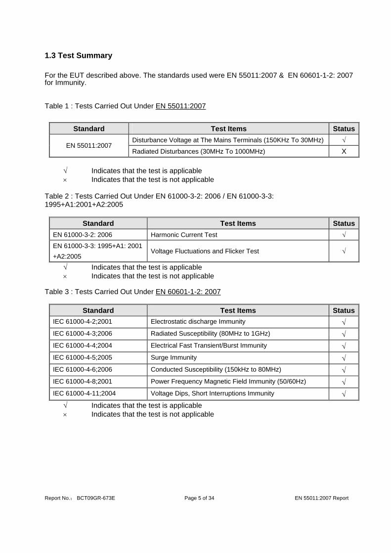
1.3 Test Summary For the EUT described above. The standards used were EN 55011:2007 & EN 60601-1-2: 2007 for Immunity.
Table 1 : Tests Carried Out Under EN 55011:2007
Standard Test Items Status
Disturbance Voltage at The Mains Terminals (150KHz To 30MHz) √ EN 55011:2007
Radiated Disturbances (30MHz To 1000MHz) X √ Indicates that the test is applicable × Indicates that the test is not applicable
Table 2 : Tests Carried Out Under EN 61000-3-2: 2006 / EN 61000-3-3: 1995+A1:2001+A2:2005
Standard Test Items StatusEN 61000-3-2: 2006 Harmonic Current Test √
EN 61000-3-3: 1995+A1: 2001 +A2:2005
Voltage Fluctuations and Flicker Test √
√ Indicates that the test is applicable × Indicates that the test is not applicable
Table 3 : Tests Carried Out Under EN 60601-1-2: 2007
Standard Test Items StatusIEC 61000-4-2;2001 Electrostatic discharge Immunity √ IEC 61000-4-3;2006 Radiated Susceptibility (80MHz to 1GHz) √ IEC 61000-4-4;2004 Electrical Fast Transient/Burst Immunity √ IEC 61000-4-5;2005 Surge Immunity √ IEC 61000-4-6;2006 Conducted Susceptibility (150kHz to 80MHz) √ IEC 61000-4-8;2001 Power Frequency Magnetic Field Immunity (50/60Hz) √ IEC 61000-4-11;2004 Voltage Dips, Short Interruptions Immunity √
√ Indicates that the test is applicable × Indicates that the test is not applicable

Report No.; BCT09GR-673E Page 6 of 34 EN 55011:2007 Report
1.4 Test Methodology All measurements contained in this report were conducted with CISPR 16-1: 2002, radio disturbance and immunity measuring apparatus, and CISPR16-2: 2002, Method of measurement of disturbances and immunity. All measurement required was performed at laboratory of Bontek Compliance Testing Laboratory Ltd. at 1/F, Block East H-3, OCT Eastern Ind. Zone, Qiaocheng East Road, Nanshan, Shenzhen, China 1.5 Test Facility The test facility is recognized, certified, or accredited by the following organizations:
FCC – Registration No.: 338263 Bontek Compliance Testing Laboratory Ltd, EMC Laboratory has been registered and fully described in a report filed with the (FCC) Federal Communications Commission. The acceptance letter from the FCC is maintained in our files. Registration 338263, March, 2008. IC Registration No.: 126111
The 3m alternate test site of Bontek Compliance Testing Laboratory Ltd EMC Laboratory has been registered by Certification and Engineer Bureau of Industry Canada for the performance of with Registration NO.: 126111 on March, 2008.

Report No.; BCT09GR-673E Page 7 of 34 EN 55011:2007 Report
1.6 Test Equipment List and Details Test equipments list of Bontek Compliance Testing Laboratory Ltd.
Equipment Manufacturer Model No. calibration date
calibration date
EMI Test Receiver R&S ESCI 2009-2-22 2010-2-21
EMI Test Receiver R&S ESPI 2009-2-22 2010-2-21
Amplifier HP 8447D 2009-2-22 2010-2-21
Single Power Conductor Module FCC FCC-LISN-5-50-1-01-CISPR25 2009-2-22 2010-2-21
Single Power Conductor Module FCC FCC-LISN-5-50-1-01-CISPR25 2009-2-22 2010-2-21
Power Clamp SCHWARZBECK MDS-21 2009-2-22 2010-2-21
Positioning Controller C&C CC-C-1F 2009-2-22 2010-2-21
Electrostatic Discharge Simulator TESEQ NSG437 2009-3-31 2010-3-30
Fast Transient Burst Generator SCHAFFNER MODULA6150 2009-2-22 2010-2-21
Fast Transient Noise Simulator Noiseken FNS-105AX 2009-2-22 2010-2-21
Color TV Pattern Generator PHILIPS PM5418 N/A N/A Power Frequency Magnetic Field
Generator EVERFINE EMS61000-8K 2009-2-22 2010-2-21
Capacitive Coupling Clamp TESEQ CDN8014 2009-2-22 2010-2-21
High Field Bucolical Antenna ELECTRO-METRICS EM-6913 2008-9-04 2009-9-03
Log Periodic Antenna ELECTRO-METRICS EM-6950 2008-9-04 2009-9-03
Remote Active Vertical Antenna ELECTRO-METRICS EM-6892 2008-9-04 2009-9-03
TRILOG Broadband Test-Antenna SCHWARZBECK VULB9163 2009-2-22 2010-2-21
Horn Antenna SCHWARZBECK BBHA9120A 2009-2-27 2010-2-26
Toe Line Single Phase Module SCHWARZBECK NSLK8128 2009-3-31 2010-3-30
10dB attenuator SCHWARZBECK MTAIMP-136 2009-2-22 2010-2-21
Electric Bridge Zentech 100 LCR METER N/A N/A
RF Current Probe FCC F-33-4 2008-9-22 2009-9-21
SIGNAL GENERATOR HP 8647A 2008-11-10 2009-11-9
MICROWAVE AMPLIFIER HP 8349B 2008-11-10 2009-11-9
Triple-Loop Antenna EVERFINE LLA-2 2009-2-27 2010-2-26

Report No.; BCT09GR-673E Page 8 of 34 EN 55011:2007 Report
2 - SYSTEM TEST CONFIGURATION 2.1 Justification The system was configured for testing in a typical fashion (as normally used by a typical user). 2.2 EUT Exercise Software The EUT exercising program used during radiated and conducted testing was designed to exercise the various system components in a manner similar to a typical use. The software offered by manufacture, can let the EUT being normal operation. 2.3 Special Accessories As shown in section 2.5, interface cable used for compliance testing is shielded as normally supplied by SHENZHEN H-ONE ELECTRICAL APIANCES CO.,LTD and its respective support equipment manufacturers. 2.4 Equipment Modifications The EUT tested was not modified by BCT. 2.5 Configuration of Test System Power Supply 2.6 Test Setup Diagram
EUT
EUT
1.0m
1.5m
AUX
AUX POWER

Report No.; BCT09GR-673E Page 9 of 34 EN 55011:2007 Report
3 - DISTURBANCE VOLTAGE AT THE MAINS TERMINALS 3.1 Measurement Uncertainty All measurements involve certain levels of uncertainties, especially in field of EMC. The factors contributing to uncertainties are spectrum analyzer, cable loss, and LISN. The Treatment of Uncertainty in EMC Measurements, the best estimate of the uncertainty of any conducted emissions measurement is +2.4 dB. 3.2 Limit of Disturbance Voltage At The Mains Terminals (Class B)
Limits ( dBuV) Frequency Range (MHz) Quasi-Peak Average
0.150~0.500 66~56 56~46 0.500~5.000 56 46 5.000~30.00 60 50
Note: (1)The tighter limit shall apply at the edge between two frequency bands. 3.3 EUT Setup The setup of EUT is according with CISPR 16-1: 2002, CISPR16-2: 2002 measurement procedure. The specification used was the EN 55022 limits. The EUT was placed center and the back edge of the test table. The AV cables were draped along the test table and bundled to 30-40cm in the middle. The spacing between the peripherals was 10 cm. Maximum emission emitted from EUT was determined by manipulating the EUT, support equipment, interconnecting cables and varying the mode of operation and the levels in the final result of the test were recorded with the EUT running in the operating mode that maximum emission was emitted. 3.4 Instruments Setup The receiver was set with the following configurations: Test Receiver Setting: Frequency Range……………………….150 KHz to 30 MHz Detector…………………………………..Peak & Quasi-Peak & Average Sweep Speed……………………………Auto IF Band Width……………………….…..9 KHz

Report No.; BCT09GR-673E Page 10 of 34 EN 55011:2007 Report
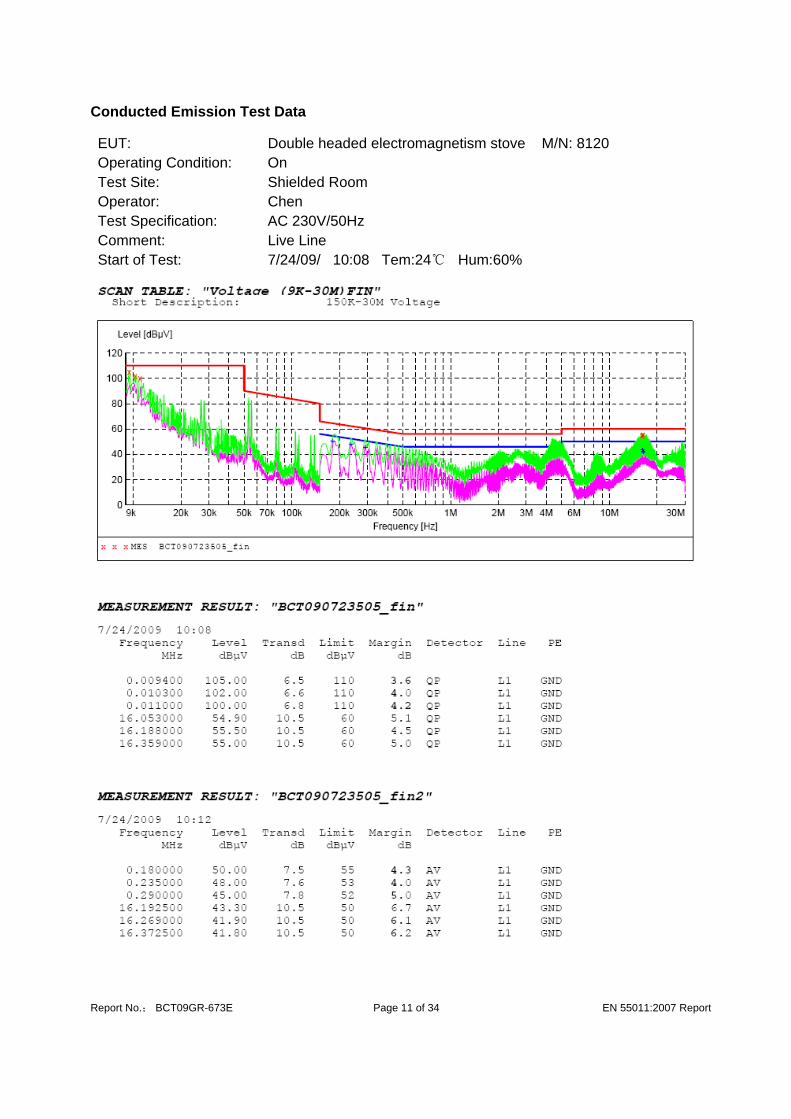
3.5 Test Procedure During the conducted emission test, the EUT power cord was connected to the auxiliary outlet of the first Artificial Mains. Maximizing procedure was performed on the six (6) highest emissions to ensure EUT compliance using all installation combination. All data was recorded in the peak detection mode. Quasi-peak and Average readings were only performed when an emission was found to be marginal (within -10 dBμV of specification limits). Quasi-peak readings are distinguished with a "QP". Average readings are distinguished with a "AV". 3.6 Summary of Test Results According to the data in section 3.6, the EUT complied with the EN 55011 Conducted margin, with the worst margin reading of:
3.7 Disturbance Voltage Test Data
Temperature ( ℃ ) 22~24 Humidity ( %RH ) 50~60 Barometric Pressure ( mbar ) 950~1000 EUT Double headed electromagnetism stove M/N 8120 Operating Mode On
Test data see following pages (Page11~12) Remark: (1) When PK reading is less than relevant limit 20dB, the QP reading and AV reading
will not be recorded. (2) Where QP reading is less than relevant AV limit, the AV reading will not be
measured 3.8 Test Result
Pass
Report No.; BCT09GR-673E Page 11 of 34 EN 55011:2007 Report
Conducted Emission Test Data EUT: Double headed electromagnetism stove M/N: 8120 Operating Condition: On Test Site: Shielded Room Operator: Chen Test Specification: AC 230V/50Hz Comment: Live Line Start of Test: 7/24/09/ 10:08 Tem:24℃ Hum:60%

Report No.; BCT09GR-673E Page 12 of 34 EN 55011:2007 Report
Conducted Emission Test Data EUT: Double headed electromagnetism stove M/N: 8120 Operating Condition: On Test Site: Shielded Room Operator: Chen Test Specification: AC 230V/50Hz Comment: Neutral Line Start of Test: 7/24/09/ 10:14 Tem:24℃ Hum:60%

Report No.; BCT09GR-673E Page 13 of 34 EN 55011:2007 Report
4- Magnetic Field Emission Test 4.1 Measurement Uncertainty All measurements involve certain levels of uncertainties, especially in field of EMC. The factors contributing to uncertainties are test receiver, cable loss, antenna factor calibration, antenna directivity, antenna factor variation with height, antenna phase center variation, antenna factor frequency interpolation, measurement distance variation, site imperfections, mismatch (average), and system repeatability. 4.2 Limit of Magnetic Field Emission
Frequency (MHz) Limit For Loop Diameter of 2m (dBμA))
9K~70K 88 70K~150K 88 ~58 150K~2.2M 58~26 2.2M~3.0M 58 3.0M~30M 22
Note: (1) The tighter limit shall apply at the edge between two frequency bands.
4.3 EUT Setup The Magnetic Field Emission tests were performed with a triple-loop antenna, using the setup accordance with the CISPR 16-1: 2002, CISPR16-2: 2002. The specification used was EN 55015 limits for Magnetic Field Emission. The EUT was placed on the center of the test table. Maximum emission emitted from EUT was determined by manipulating the EUT, support equipment, interconnecting cables and varying the mode of operation and the levels in the final result of the test were recorded with the EUT running in the operating mode that maximum emission was emitted. 4.4 Test Receiver Setup
According to EN 55015 rules, the frequency was investigated from 9KHz to 150KHz / 150KHz to 30MHz. During the Magnetic Field emission test, the test receiver was set with the following configurations: Test Receiver Setting: Frequency Range……………………….9KHz to 30 MHz Detector…………………………………..Peak & Quasi-Peak IF Band Width……………………….…..200Hz / 9KHz Frequency Range……………………….9KHz to 150KHz / 150KHz to 30MHz 4.5 Test Procedure EUT is placed in the center of triple-loop antenna (Diameter is 2m). Turn on the EUT, then the induced current in the loop antenna can be detected by a current probe and measured by the

Report No.; BCT09GR-673E Page 14 of 34 EN 55011:2007 Report
receiver. Three field directions shall be measured in sequence. Maximizing procedure was performed on the highest emissions to ensure that the EUT complied with all installation combinations. All data was recorded in the peak detection mode. Quasi-peak and Average readings were only performed when an emission was found to be marginal (within -10 dBμV of specification limits). Quasi-peak readings are distinguished with a "QP". Average readings are distinguished with a "AV". 4.6 Corrected Amplitude & Margin Calculation The Corrected Amplitude is calculated by adding the Antenna Factor and Cable Factor, and subtracting the Amplifier Gain from the Amplitude reading. The basic equation is as follows:
Corr. Ampl. = Indicated Reading + Antenna Factor + Cable Factor - Amplifier Gain The “Margin” column of the following data tables indicates the degree of compliance with the applicable limit. For example, a margin of -7dBμA means the emission is 7dBμA below the maximum limit. The equation for margin calculation is as follows:
Margin = Corr. Ampl. – Limit 4.7 Radiated Emissions Test Result
Temperature ( ℃ ) 22~24 Humidity ( %RH ) 50~60 Barometric Pressure ( mbar ) 950~1000 EUT Double headed electromagnetism stove M/N 8120 Operating Mode On
Test data see following pages (Page15~17) Remark: (1) When PK reading is less than relevant limit 20dB, the QP reading and AV reading
will not be recorded. (2) Where QP reading is less than relevant AV limit, the AV reading will not be
measured 4.8 Test Result
Pass

Report No.; BCT09GR-673E Page 15 of 34 EN 55011:2007 Report
Magnetic Field Emission Test Data EUT: Double headed electromagnetism stove M/N: 8120 Operating Condition: On Test Site: Shielded Room Operator: Jip Test Specification: AC 230V/50Hz Comment: Polarization: X Tem:24℃ Hum:60% Start of Test: 07/21/09/ 18:20

Report No.; BCT09GR-673E Page 16 of 34 EN 55011:2007 Report
Magnetic Field Emission Test Data EUT: Double headed electromagnetism stove M/N: 8120 Operating Condition: On Test Site: Shielded Room Operator: Jip Test Specification: AC 230V/50Hz Comment: Polarization: Y Tem:24℃ Hum:60% Start of Test: 07/21/09/ 18:43

Report No.; BCT09GR-673E Page 17 of 34 EN 55011:2007 Report
Magnetic Field Emission Test Data EUT: Double headed electromagnetism stove M/N: 8120 Operating Condition: On Test Site: Shielded Room Operator: Jip Test Specification: AC 230V/50Hz Comment: Polarization: Z Tem:24℃ Hum:60% Start of Test: 07/21/09/ 18:41

Report No.; BCT09GR-673E Page 18 of 34 EN 55011:2007 Report
5 – HARMONIC CURRENT TEST (EN 61000-3-2) 5.1 Application of Harmonic Current Emission Compliance to these standards ensures that tested equipment will not generate harmonic currents at levels that cause unacceptable degradation of the main environment. This directly contributes to meeting compatibility levels established in other EMC standards, which defines compatibility levels for low-frequency conducted disturbances in low-voltage supply systems. 5.2 Measurement Data Note: For detailed test data, refer to the following pages: Standard used EN/IEC 61000-3-2 A14 (2000) Quasi-stationary -
Equipment class A Observation time 150s
EUT Double headed electromagnetism stove
M/N 8120
Operating Mode On
Test Result
E. U. T.: PASS
Power Source: PASS 5.3 Test Results
Pass

Report No.; BCT09GR-673E Page 19 of 34 EN 55011:2007 Report
6 – VOLTAGE FLUCTUATIONS AND FLICKER TEST (EN 61000-3-3) 6.1 Application of Voltage Fluctuations and Flicker Test Compliance to these standards ensures that tested equipment will not generate flickers and voltage change at levels that cause unacceptable degradation of the main environment. This directly contributes to meeting compatibility levels established in other EMC standards, which defines compatibility levels for low-frequency conducted disturbances in low-voltage supply systems. 6.2 Measurement Data Standard used EN/IEC 61000-3-3 Flicker
Short time (Pst) 10 min
Observation time 10 min (1 Flicker measurement)
Flickermeter AC 230V / 50Hz
EUT Double headed electromagnetism stove
M/N 8120
Operating Mode On
6.3 Test Results Pass

Report No.; BCT09GR-673E Page 20 of 34 EN 55011:2007 Report
7 – EN 60601-1-2:2007 MEASUREMENT INSTRUMENTATION 7.1 Electrostatic Discharge Test System An EM TEST DITOC0103Z ESD simulator is used for all testing. It is capable of applying Electrostatic discharges in both contact discharge modes to 6 kV and air discharge modes to 8 kV in both positive and negative polarities. This is in accordance with the IEC 61000-4-2 basic EMC publication. 7.2 Radiated Susceptibility Test System An IFR 2032 signal generator and a Amplifier Research power amplifier are used to provide a signal at the appropriate power and frequency to a transmitting antenna to obtain the required electromagnetic field at the position of the EUT in accordance with the IEC 61000-4-3 basic EMC publication. The field was monitored by Amplifier Research field probe and Amplifier Research PM2002 power meter according the IEC 61000-4-3 standards.In order to judge the performance of the EUT, a set of monitor system is used. 7.3 Electrical Fast Transient/Burst Immunity Test System An EM Test UCS 500-M6 Immunity test system is used for all testing. It is capable of applying fast transients to the AC line at any phase angle with respect to the AC line voltage wave form and to attached cables via a capacitive coupling clamp in accordance with the IEC 61000-4-4 basic EMC publication. 7.4 Surge Immunity Test System An EM Test UCS 500-M6 Immunity test system is used for all testing. Both positive and negative polarities of voltage up to 2kV were applied to the AC input lines. The coupling network defined in the standard was used. 7.5 Conducted Susceptibility Test System An IFR 2032A signal generator and a set of Amplifier Research test system are used for the testing. EUT was tested from 0.15 MHz to 80 MHz with 1kHz sine wave, 80% modulation with 3Vr.m.s. CDN coupling and de-coupling networks and EM clamp was tested. During the tests, injected was applied to power line by using CDNs-6.2.2 method, and I/O lines was injected by using EM clamp injection-6.2.3.method. 7.6 Power Frequency Magnetic Field Immunity Test System An EM Test UCS 500-M6 Immunity test system is used for all testing. Test level as described in IEC 61000-4-8 titled “Table 1 – Test Levels for continuous field” was chosen. Single turn induction coil in 1m x 1m size was used to generate the magnetic field. 7.7 Voltage Dips, Short Interruptions Immunity Tests System An EM Test UCS 500-M6 Immunity test system is used for all testing. Test level as described in IEC 61000-4-11, section 5, titled “Test Levels”.

Report No.; BCT09GR-673E Page 21 of 34 EN 55011:2007 Report
7.8 Equipment Test Table IEC 61000-4-2: 1995 specifies that a tabletop EUT shall be placed on a non-conducting table which is 80 centimeters above a ground reference plane and that floor mounted equipment shall be placed on a insulating support approximately 10 centimeters above a ground plane. During the tests, the EUT is positioned over a ground reference plane in conformance with this requirement. For tabletop equipment, a 1.6 by 0.8-meter metal sheet (HCP) is placed on the table and connected to the ground plane via a metal strap with two 470 k Ohms resistors in series. The EUT and attached cables are isolated from this metal sheet by 0.5-millimeter thick insulating material. A Vertical Coupling Plane (VCP) grounded on the ground plane through the same configuration as in the HCP is used. IEC 61000-4-3 and IEC 61000-4-4 specify that a tabletop EUT be placed on a non-conducting table 80 centimeters above a ground reference plane and that floor-mounted equipment shall be placed on an insulating support approximately 10 centimeters above a ground plane. During the IEC 61000-4-3 tests, the EUT is positioned on a table in a shielded semi-anechoic test chamber to reduce reflections from the internal surfaces of the chamber. During the IEC 61000-4-4 tests, the EUT is positioned on a table over a ground reference plane in conformance with this requirement. 7.9 Instrument Calibration All test equipment is regularly checked to ensure that performance is maintained in accordance with the manufacturer's specifications. Extensive engineering efforts have been made to ensure test data reliability through Quality Control and regular equipment calibration schedules. However, the application of radio frequency fields and voltages are not without an unavoidable level of uncertainty. These include inaccuracies in antenna factors, chamber imperfections and possible test generator output uncertainties.

Report No.; BCT09GR-673E Page 22 of 34 EN 55011:2007 Report
8 - EN 60601-1-2:2007 TEST PROCEDURES 8.1 EUT and Cable Placement The EUT and any peripherals are located at the center of the table for tabletop devices and in the center of the ground plane with the insulating support for floor-standing devices. The standards require that interconnecting cables to be connected to available ports of the unit and that the placement of the unit and the attached cables simulate a typical installation so far as to be practical. 8.2 Application of Electrostatic Discharge Immunity Test The test is conducted in the following order according to the basic standard IEC 61000-4-2: Air Discharge, Direct Contact Discharge, Indirect Contact Horizontal Coupling Plane Discharge, and Indirect Contact Vertical Coupling Plane Discharge. The Electrostatic Discharge test levels are set and discharges for the different test modes are set appropriately. The Electrostatic Discharge is applied to the conductive surface of the EUT, and along all seams and control surfaces on the EUT. When a discharge occurs and an error is caused, the type of error, discharge level and location is recorded. 8.3 Application of Radiated Susceptibility Test The electromagnetic field is established at the front edge of the EUT. The frequency range is swept from 80 - 1000 MHz,1000 - 2500 MHz using a power level necessary to obtain a 3 volt/meter and 80% amplitude of a 2Hz sine wave modulated field Strength is directed at the EUT. The test is performed with each of four sides of EUT facing the transmitting antenna. If an error is detected when the susceptible side of the EUT facing the transmitting antenna, the field is reduced until the error is not repeatable, the field is then manually increased until the error begins to occur. This threshold level, the frequency and the error created are noted before continuing. Both horizontal and vertical polarization of the antenna are set on test and measured individually 8.4 Application of Electrical Fast Transient/Burst Immunity Test The EUT was arranged for Power Line Coupling and for I/O Line Coupling through a capacitive clamp, where applicable. (Note: The I/O coupling test using a capacitive clamp is performed on the I/O interface cables that are longer in length than 3 meters.) A metal ground plane 2.4 meter by 2.0 meter was placed between the floor and the table and is connected to the earth by a 2.0 meter ground rod. The ground rod is connected to the test facility’s electrical earth. 8.5 Application of Surge Immunity Test The EUT was setup as described in IEC 61000-4-5 and the test shall be performed according to the test plan. 8.6 Application of Conducted Susceptibility Test The EUT was setup according to the IEC 61000-4-6 and the test shall be performed with the test generator connected to each of the coupling and decoupling devices in turn while the other non-excited RF input ports of the coupling devices are terminated by a 50 Ω load resistor. The frequency range is 150kHz to 80 MHz.

Report No.; BCT09GR-673E Page 23 of 34 EN 55011:2007 Report
8.7 Application of Power Frequency Magnetic Field Immunity Test It is deemed that according to the standard of EN 60601-1-2:2007 this test is not applicable to the EUT which dose not contain devices susceptible to magnetic fields, such as CRT monitors, Hall elements, electro-dynamic microphone, magnetic field sensor, etc. 8.7 Application of Voltage Dips, Short Interruptions Immunity Tests The EUT was setup according to the IEC 61000-4-11 and the test shall be done as the procedure described in the standard. 8.8 Deviations from the Standard No deviations from EN 60601-1-2:2007 were made when performing the tests described in this report.

Report No.; BCT09GR-673E Page 24 of 34 EN 55011:2007 Report
9 - TEST DATA 9.1 Electrostatic Discharge Immunity Test (IEC 61000-4-2)
Temperature ( ℃ ) 22~23 Humidity ( %RH ) 50~54 Barometric Pressure ( mbar ) 950~1000 EUT Double headed electromagnetism stove M/N 8120 Operating Mode On
Table 1: Electrostatic Discharge Immunity (Air Discharge)
Test Levels IEC 61000-4-2 Test Points -2 kV +2 kV -4 kV +4 kV -6 kV +6 kV -8 kV +8 kV -15 kV +15 kV
Slots 2 points A A A A A A A A / / Control Keypad A A A A A A A A / /
Table 2: Electrostatic Discharge Immunity (Direct Contact)
Test Levels IEC 61000-4-2 Test Points -2 kV +2 kV -4 kV +4 kV -6 kV +6 kV -8 kV +8 kV -15 kV +15 kV
Bolots 2 points A A A A A A / / / / Shell 5 points A A A A A A / / / /
Table 3: Electrostatic Discharge Immunity (Indirect Contact HCP)
Test Levels IEC 61000-4-2 Test Points -2 kV +2 kV -4 kV +4 kV -6 kV +6 kV -8 kV +8 kV -15 kV +15 kV
Front Side A A A A A A / / / / Back Side A A A A A A / / / / Left Side A A A A A A / / / / Right Side A A A A A A / / / /
Table 4: Electrostatic Discharge Immunity (Indirect Contact VCP)
Test Levels IEC 61000-4-2 Test Points -2 kV +2 kV -4 kV +4 kV -6 kV +6 kV -8 kV +8 kV -15 kV +15 kV
Front Side A A A A A A / / / / Back Side A A A A A A / / / / Left Side A A A A A A / / / / Right Side A A A A A A / / / /
Report No.; BCT09GR-673E Page 25 of 34 EN 55011:2007 Report
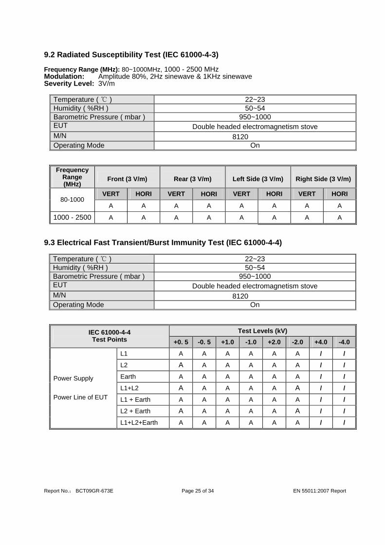
9.2 Radiated Susceptibility Test (IEC 61000-4-3) Frequency Range (MHz): 80~1000MHz, 1000 - 2500 MHz Modulation: Amplitude 80%, 2Hz sinewave & 1KHz sinewave Severity Level: 3V/m
Temperature ( ℃ ) 22~23 Humidity ( %RH ) 50~54 Barometric Pressure ( mbar ) 950~1000 EUT Double headed electromagnetism stove M/N 8120 Operating Mode On
Frequency Range (MHz)
Front (3 V/m) Rear (3 V/m) Left Side (3 V/m) Right Side (3 V/m)
VERT HORI VERT HORI VERT HORI VERT HORI 80-1000
A A A A A A A A
1000 - 2500 A A A A A A A A 9.3 Electrical Fast Transient/Burst Immunity Test (IEC 61000-4-4)
Temperature ( ℃ ) 22~23 Humidity ( %RH ) 50~54 Barometric Pressure ( mbar ) 950~1000 EUT Double headed electromagnetism stove M/N 8120 Operating Mode On
Test Levels (kV) IEC 61000-4-4 Test Points +0. 5 -0. 5 +1.0 -1.0 +2.0 -2.0 +4.0 -4.0
L1 A A A A A A / /
L2 A A A A A A / /
Earth A A A A A A / /
L1+L2 A A A A A A / /
L1 + Earth A A A A A A / /
L2 + Earth A A A A A A / /
Power Supply Power Line of EUT
L1+L2+Earth A A A A A A / /

Report No.; BCT09GR-673E Page 26 of 34 EN 55011:2007 Report
9.4 Surge Immunity Test (IEC 61000-4-5)
Temperature ( ℃ ) 22~23 Humidity ( %RH ) 50~54 Barometric Pressure ( mbar ) 950~1000 EUT Double headed electromagnetism stove M/N 8120 Operating Mode On
Table 1: Surge Power Supply
Level Voltage Poll Path Pass Fail 1 0.5kV ± L-N A / 2 1kV ± L-N A / 3 2kV ± L-PE, N-PE A / 4 4kV ± L-N, L-PE, N-PE / /
9.5 Conducted Susceptibility Test (IEC 61000-4-6) Frequency Range (MHz): 0.15~80MHz Modulation: Amplitude 80%, 2Hz sinewave & 1KHz sinewave Severity Level: 3Vr.m.s.
Temperature ( ℃ ) 22~23 Humidity ( %RH ) 50~54 Barometric Pressure ( mbar ) 950~1000 EUT Double headed electromagnetism stove M/N 8120 Operating Mode On
Level Voltage Level (e.m.f.) U0
Pass Fail
1 1 / / 2 3 A / 3 10 / / X Special / /

Report No.; BCT09GR-673E Page 27 of 34 EN 55011:2007 Report
9.6 Voltage Dips, Short Interruptions Immunity Tests (IEC 61000-4-11)
Temperature ( ℃ ) 22~23 Humidity ( %RH ) 50~54 Barometric Pressure ( mbar ) 950~1000 EUT Double headed electromagnetism stove M/N 8120 Operating Mode On
Level U2 td Phase Angle N Pass Fail 1 >95% 10s 0/90/180/270 3 B /
2 70% 500s N/A 3 C / 3 40% 100s N/A 3 C / 4 2% 5s N/A 3 C /
Note:
A. The apparatus shall continue to operate as intended during and after the test. The manufacturer specifies some minimum performance level. The performance level may be specified by the manufacturer as a permissible loss of performance.
B. The apparatus shall continue to operate as intended after the test. This
indicates that the EUT does not need to function at normal performance levels during the test, but must recover. Again some minimal performance is defined by the manufacture. No change in operating state or loss or data is permitted.
C. Temporary loss of function is allowed. Operation of the EUT may stop as long
as it is either automatically reset or can be manually restored by operation of the controls.

Report No.; BCT09GR-673E Page 28 of 34 EN 55011:2007 Report
10 - TEST RESULTS The following tests were performed on the SHENZHEN H-ONE ELECTRICAL APIANCES CO.,LTD’s product; model: 8120; the actual test results are contained within the Test Data section of this report. 10.1 IEC 61000-4-2 Electrostatic Discharge Immunity Test Configuration The EUT was subjected to the electrostatic discharge tests required by EN 60601-1-2:2001 and all lower levels specified in IEC 61000-4-2.
The EUT continued to perform as intended during and after the application of the ESD. Test setup photographs presented in Appendix C.
10.2 IEC 61000-4-3 Radiated Susceptibility Test Configuration The EUT was subjected to a 3-volt/meter, 80% Amplitude, 2Hz Sine wave field as required by EN 60601-1-2:2001 and all lower levels specified in IEC 61000-4-3.
The EUT continued to perform as intended during and after the application of the electromagnetic field. Test setup photographs presented in Appendix C.
10.3 IEC 61000-4-4 Electrical Fast Transient/Burst Immunity Test Configuration The EUT was subjected to the electrical fast transient tests required by EN 60601-1-2:2001 and all lower levels specified in IEC 61000-4-4.
The EUT continued to perform as intended during and after the application of the EFT/B. Test setup photographs presented in Appendix C.
10.4 IEC 61000-4-5 Surge Immunity Test Configuration The EUT was subjected to the Surge Immunity tests required by EN 60601-1-2:2001 and all lower levels specified in IEC 61000-4-5.
The EUT continued to perform as intended during and after the application of the Surge Immunity Test. Test setup photographs presented in Appendix C.
10.5 IEC 61000-4-6 Conducted Susceptibility Test Configuration
The EUT was subjected to the Conducted Susceptibility tests required by EN 60601-1-2:2001 and all lower levels specified in IEC 61000-4-6.
The EUT continued to perform as intended during and after the application of the Conducted Susceptibility Test. Test setup photographs presented in Appendix C.
10.6 IEC 61000-4-11 Voltage Dips, Short Interruptions Immunity Tests Configuration The EUT was subjected to the Voltage Dips/Interruptions tests required by EN 60601-1-2:2001 and all lower levels specified in IEC 61000-4-11.
The EUT continued to perform as intended during and after the application of the Voltage Dips/Interruptions Test. Test setup photographs presented in Appendix C.

Report No.; BCT09GR-673E Page 29 of 34 EN 55011:2007 Report
APPENDIX A - PRODUCT LABELING CE Marking Label Specification Specification: Text is Black or white in color and is left justified. Labels are printed in indelible ink on permanent adhesive backing and shall be affixed at a conspicuous location on the
EUT or silk-screened onto the EUT.
Proposed Label Location on EUT EUT Rear View/Proposed CE Marking Location

Report No.; BCT09GR-673E Page 30 of 34 EN 55011:2007 Report
APPENDIX B - EUT PHOTOGRAPHS EUT - Front View EUT - Rear View EUT – Internal View
Report No.; BCT09GR-673E Page 31 of 34 EN 55011:2007 Report
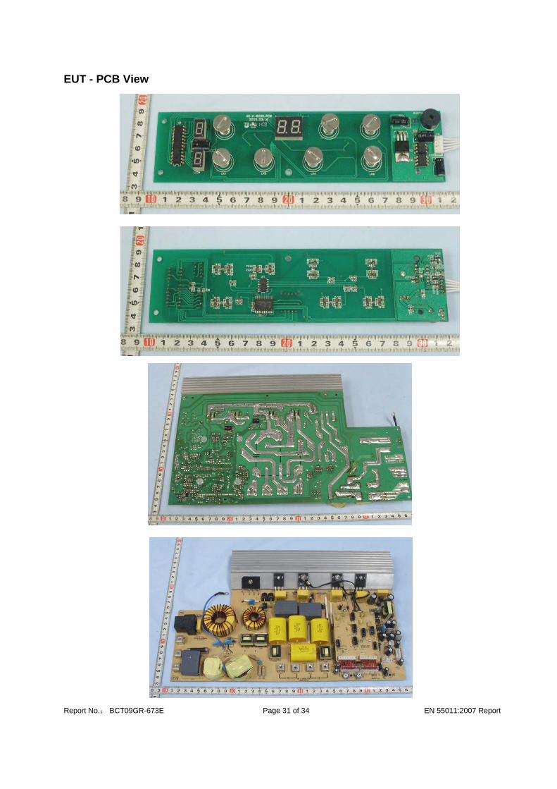
EUT - PCB View

Report No.; BCT09GR-673E Page 32 of 34 EN 55011:2007 Report
APPENDIX C - SUBSIDIARY MODEL Model: 8121

Report No.; BCT09GR-673E Page 33 of 34 EN 55011:2007 Report
APPENDIX D - TEST SETUP PHOTOGRAPHS Conducted Emission Magnetic Field Emission Test Radiated Susceptibility Test (IEC 61000-4-3)

Report No.; BCT09GR-673E Page 34 of 34 EN 55011:2007 Report
Electrostatic Discharge Immunity Test (IEC 61000-4-2) Electrical Fast Transient/Burst Immunity Test (IEC 61000-4-4) Voltage Dips, Short Interruptions Immunity Test (IEC 61000-4-11)