en knx rw - id eide.com.pl/.../knx_rw/knx_rw_manual_en.pdf · rain/wind sensor knx rw • date of...
TRANSCRIPT

Installation and Adjustment
EN
Elsner Elektronik GmbH Control and Automation TechnologyHerdweg 7D – 75391 Gechingen Phone +49 (0) 70 56 / 93 97-0 [email protected] Fax +49 (0) 70 56 / 93 97-20 www.elsner-elektronik.de
KNX RWRain / Wind Sensor
1 Content
1. Description ........................................................................................... 3
1.1. Technical specifications ........................................................................................... 3
2. Installation and commissioning ........................................................... 4
2.1. Notes on installation ................................................................................................ 42.2. Location ..................................................................................................................... 5
2.3. Mounting the sensor ................................................................................................ 6
2.3.1. Attaching the mount ..................................................................................... 6
2.3.2. View of rear side and drill hole plan ........................................................... 7
2.3.3. Preparing the sensor .................................................................................... 8
2.3.4. PCB Layout .................................................................................................... 9
2.3.5. Mounting the sensor .................................................................................. 10
2.4. Notes on mounting and commissioning .............................................................. 11
3. Maintenance ....................................................................................... 11
4. Transmission protocol ....................................................................... 12
4.1. List of all communication objects ......................................................................... 12
5. Setting of parameters ........................................................................ 15
5.1. General settings ..................................................................................................... 15
5.2. Threshold values .................................................................................................... 16
5.2.1. Wind threshold value 1 / 2 / 3 .................................................................... 16
5.3. Logic ........................................................................................................................ 18
5.3.1. AND Logic 1 / 2 / 3 / 4 / 5 / 6 / 7 / 8 .............................................................. 18
5.3.2. Linkage inputs of AND logic ...................................................................... 19
5.3.3. OR Logic 1 / 2 / 3 / 4 / 5 / 6 / 7 / 8 ................................................................ 20
5.3.4. Linkage inputs of OR logic ......................................................................... 20
Elsner Elektronik GmbH • Herdweg 7 • D-75391 Gechingen • GermanyRain/Wind Sensor KNX RW • from software version 1.00, ETS programme version1.1
Errors excepted. Subject to technical changes.

2 Content
Elsner Elektronik GmbH • Herdweg 7 • D-75391 Gechingen • GermanyRain/Wind Sensor KNX RW • from software version 1.00, ETS programme version1.1
Errors excepted. Subject to technical changes.
3 Description
1. Description
The Rain/Wind Sensor KNX RW measures precipitation and wind speed and trans-fers the values to the KNX system. Four switching outputs with three adjustable
threshold values as well as additional AND and OR logic gates are available. The sen-
sor system, the evaluation electronics and the electronics of the bus connection aremounted in a compact housing.
Functions:
• Precipitation perception: The surface of the sensor is heated so that only
drops and flakes are recognised as precipitation but not fog or dew. If it stops
raining or snowing, the sensor dries quickly and the precipitation message ends
• Wind measurement: The wind strength measurement takes place
electronically and thus noiselessly and reliably, even during hail, snow and sub-zero temperatures. Even turbulent air and anabatic winds in the vicinity of
the weather station are recorded
• 4 switching outputs, 3 with adjustable threshold values (Threshold values can be set by parameter or via communication objects)
• 8 AND and 8 OR logic gates with each 4 inputs. Every switching incident as
well as 8 logic inputs (in the form of communication objects) may be used as inputs for the logic gates. The output of each gate may optionally be configured
as 1 bit or 2 x 8 bits
Configuration is made using the KNX software ETS. The programme file (format VD),the data sheet and the manual can be downloaded from the Elsner Elektronik home-
page on www.elsner-elektronik.de in the “Service” menu.
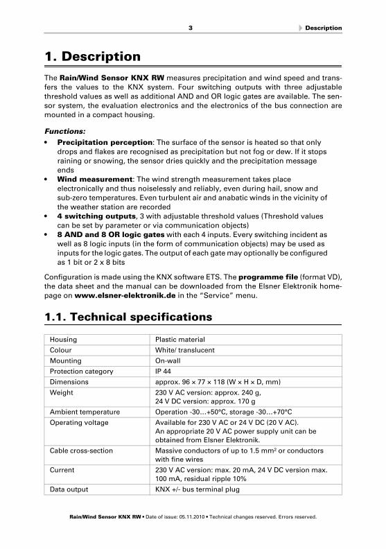
1.1. Technical specifications
Housing Plastic material
Colour White/ translucent
Mounting On-wall
Protection category IP 44
Dimensions approx. 96 × 77 × 118 (W × H × D, mm)
Weight 230 V AC version: approx. 240 g,
24 V DC version: approx. 170 g
Ambient temperature Operation -30…+50°C, storage -30…+70°C
Operating voltage Available for 230 V AC or 24 V DC (20 V AC).
An appropriate 20 V AC power supply unit can be
obtained from Elsner Elektronik.
Cable cross-section Massive conductors of up to 1.5 mm² or conductors
with fine wires
Current 230 V AC version: max. 20 mA, 24 V DC version max.
100 mA, residual ripple 10%
Data output KNX +/- bus terminal plug
Rain/Wind Sensor KNX RW • Date of issue: 05.11.2010 • Technical changes reserved. Errors reserved.
4 Installation and commissioning
The following standards have been considered for the evaluation of the product in
terms of electro magnetic compatibility: Transient emissions:
• EN 60730-1:2000 Section EMV (23, 26, H23, H26) (threshold category: B)
• EN 50090-2-2:1996-11 + A1:2002-01 (threshold category: B)• EN 61000-6-3:2001 (threshold category: B)
Interference resistance:
• EN 60730-1:2000 Section EMV (23, 26, H23, H26)• EN 50090-2-2:1996-11 + A1:2002-01
• EN 61000-6-1:2004
The product has been tested for the above mentioned standards by an accredited EMVlaboratory.
2. Installation and commissioning
2.1. Notes on installation
Warning, mains voltage! National legal regulations are to be observed.
Installation, inspection, commissioning and troubleshooting of the device must only be carried out by a competent electrician.
Disconnect all lines to be assembled, and take safety precautions against accidental
switch-on.
The device is exclusively intended for appropriate use. With each inappropriate changeor non-observance of the instructions for use, any warranty or guarantee claim will be
void.
After unpacking the device, check immediately for any mechanical damages. In case oftransport damage, this must immediately notified to the supplier.
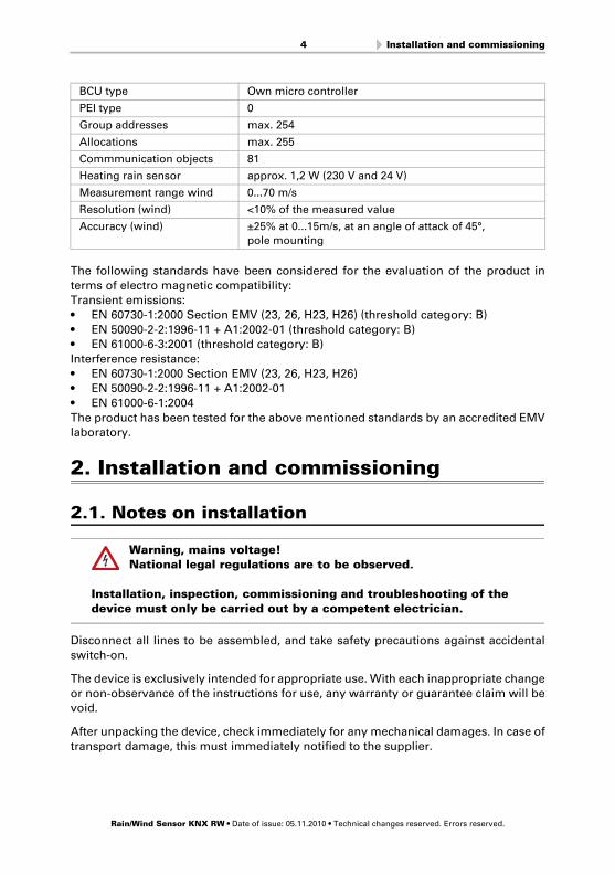
BCU type Own micro controller
PEI type 0
Group addresses max. 254
Allocations max. 255
Commmunication objects 81
Heating rain sensor approx. 1,2 W (230 V and 24 V)
Measurement range wind 0...70 m/s
Resolution (wind) <10% of the measured value
Accuracy (wind) ±25% at 0...15m/s, at an angle of attack of 45°,
pole mounting
Rain/Wind Sensor KNX RW • Date of issue: 05.11.2010 • Technical changes reserved. Errors reserved.

5 Installation and commissioning
If damaged, the device must not be put into operation.
If an operation without risk may supposedly not be guaranteed, the device must be putout of operation and be secured against accidental operation.
The device must only be operated as stationary system, i.e. only in a fitted state and
after completion of all installation and start-up works, and only in the environment in-
tended for this purpose.
Elsner Elektronik does not assume any liability for changes in standards after publica-
tion of this instruction manual.
2.2. Location
Select an assembly location at the building where precipitation and wind may be coll-
ected by the sensors unobstructedly. Do not assemble any construction components
above the sensor from where water may drop on to the rain and wind sensor after ithas stopped raining or snowing. At least 60 cm of free space must be left beneath the
device to enable correct wind measurement and prevent snowing in when there is
snow.
Fig. 1The rain/wind sensor must be mounted onto
a vertical wall (or pole).
Wallor pole
Fig. 2
The rain/wind sensor must be mounted hori-
zontally in the lateral direction.Horizontal
Rain/Wind Sensor KNX RW • Date of issue: 05.11.2010 • Technical changes reserved. Errors reserved.

6 Installation and commissioning
2.3. Mounting the sensor
2.3.1. Attaching the mount
The sensor comes with a combination wall/pole mount. The mount comes adhered by
adhesive strips to the rear side of the housing.
Fasten the mount vertically onto the wall or pole.
Fig. 3
When wall mounting: flat side on wall, crescent-
shaped collar upward.Collar
Fig. 4
When pole mounting: curved side on pole, collar
downward.
Collar
Fig. 5An additional, optional accessory available from
Elsner Elektronik is an articulated arm for flexib-
le wall, pole or beam mounting of the sensor.
Rain/Wind Sensor KNX RW • Date of issue: 05.11.2010 • Technical changes reserved. Errors reserved.
7 Installation and commissioning
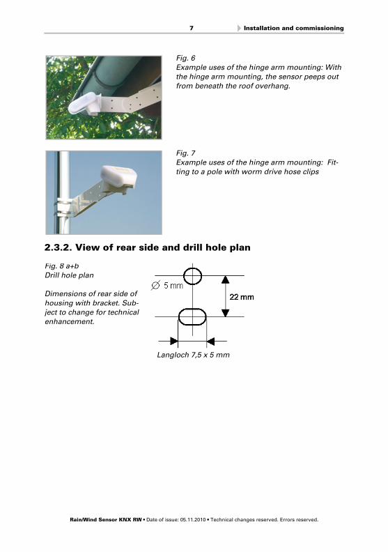
2.3.2. View of rear side and drill hole plan
Fig. 6Example uses of the hinge arm mounting: With
the hinge arm mounting, the sensor peeps out
from beneath the roof overhang.
Fig. 7Example uses of the hinge arm mounting: Fit-
ting to a pole with worm drive hose clips
Langloch 7,5 x 5 mm
Fig. 8 a+b
Drill hole plan
Dimensions of rear side of
housing with bracket. Sub-ject to change for technical
enhancement.
Rain/Wind Sensor KNX RW • Date of issue: 05.11.2010 • Technical changes reserved. Errors reserved.
8 Installation and commissioning
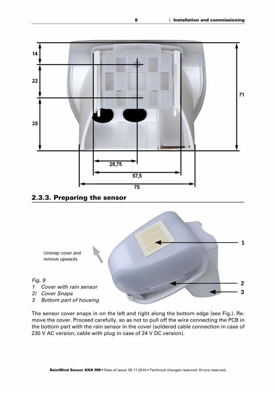
2.3.3. Preparing the sensor
The sensor cover snaps in on the left and right along the bottom edge (see Fig.). Re-
move the cover. Proceed carefully, so as not to pull off the wire connecting the PCB inthe bottom part with the rain sensor in the cover (soldered cable connection in case of
230 V AC version, cable with plug in case of 24 V DC version).
Fig. 9
1 Cover with rain sensor
2) Cover Snaps3 Bottom part of housing
23
Unsnap cover and remove upwards
1
Rain/Wind Sensor KNX RW • Date of issue: 05.11.2010 • Technical changes reserved. Errors reserved.

9 Installation and commissioning
Lead the cable for the voltage supply and bus connection through the rubber seals on
the bottom of the device and connect Voltage L/N and Bus +/- to the terminals provi-
ded.
For 24V devices the connection cable must be plugged in between the cover and circuitboard.
2.3.4. PCB Layout
230 V AC version
Fig. 10
1) Cable connection to the rain
sensor in the housing cover2) Opening for the cable for the
voltage supply
3) Tension clamp for voltage supply (230 V AC), suitable for
massive conductors of up to
1.5 mm² or conductors with fine wires
4) Slot for KNX clamp +/-
5 Opening for the bus cable6) Programming pushbutton for
the teach-in of the device
7) Programming LED
2 3
4
67
5
1
Rain/Wind Sensor KNX RW • Date of issue: 05.11.2010 • Technical changes reserved. Errors reserved.
10 Installation and commissioning
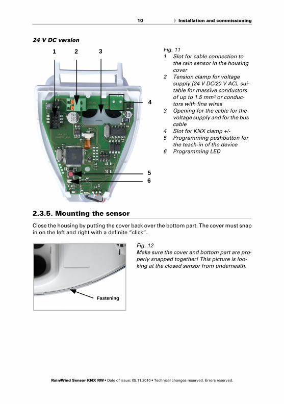
24 V DC version
2.3.5. Mounting the sensor
Close the housing by putting the cover back over the bottom part. The cover must snapin on the left and right with a definite “click”.
Fig. 111 Slot for cable connection to
the rain sensor in the housing
cover
2 Tension clamp for voltage supply (24 V DC/20 V AC), sui-
table for massive conductors
of up to 1.5 mm² or conduc-tors with fine wires
3 Opening for the cable for the
voltage supply and for the bus cable
4 Slot for KNX clamp +/-
5 Programming pushbutton for the teach-in of the device
6 Programming LED
1 2
4
3
56
Fig. 12
Make sure the cover and bottom part are pro-perly snapped together! This picture is loo-
king at the closed sensor from underneath.
Fastening
Rain/Wind Sensor KNX RW • Date of issue: 05.11.2010 • Technical changes reserved. Errors reserved.
11 Maintenance
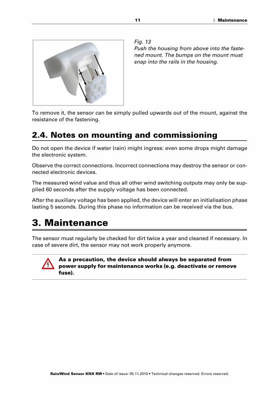
To remove it, the sensor can be simply pulled upwards out of the mount, against the
resistance of the fastening.
2.4. Notes on mounting and commissioning
Do not open the device if water (rain) might ingress: even some drops might damage
the electronic system.
Observe the correct connections. Incorrect connections may destroy the sensor or con-nected electronic devices.
The measured wind value and thus all other wind switching outputs may only be sup-
plied 60 seconds after the supply voltage has been connected.
After the auxiliary voltage has been applied, the device will enter an initialisation phase
lasting 5 seconds. During this phase no information can be received via the bus.
3. Maintenance
The sensor must regularly be checked for dirt twice a year and cleaned if necessary. In
case of severe dirt, the sensor may not work properly anymore.
As a precaution, the device should always be separated from power supply for maintenance works (e.g. deactivate or remove
fuse).
Fig. 13Push the housing from above into the faste-
ned mount. The bumps on the mount must
snap into the rails in the housing.
Rain/Wind Sensor KNX RW • Date of issue: 05.11.2010 • Technical changes reserved. Errors reserved.

12 Transmission protocol
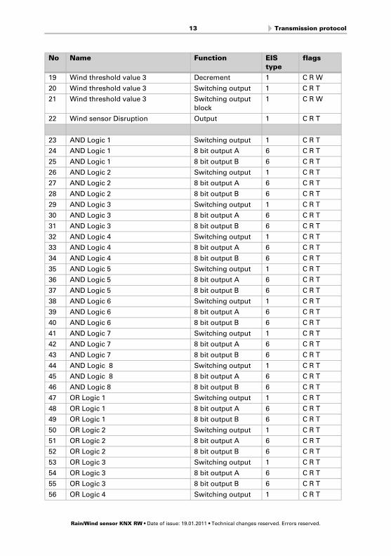
4. Transmission protocol
Units of measurement:
Wind in metre per second
4.1. List of all communication objects
Abbreviations EIS types:
1 Switching1/0
5 Floating point value
6 8 bit value
Abbreviations flags:
C CommunicationR Read
W Write
T Transmit
No Name Function EIS
type
flags
0 Wind force measured value Output 5 C R T
1 Request max. wind force Input 1 C R W
2 Max. wind force measured value Output 5 C R T
3 Reset max. wind force Input 1 C R W
4 Wind threshold value 1 16 bit value 5 C R W T
5 Wind threshold value 1 1 = Increment |
0 = Decrement
1 C R W
6 Wind threshold value 1 Increment 1 C R W
7 Wind threshold value 1 Decrement 1 C R W
8 Wind threshold value 1 Switching output 1 C R T
9 Wind threshold value 1 Switching output
block
1 C R W
10 Wind threshold value 2 16 bit value 5 C R W T
11 Wind threshold value 2 1 = Increment |
0 = Decrement
1 C R W
12 Wind threshold value2 Increment 1 C R W
13 Wind threshold value 2 Decrement 1 C R W
14 Wind threshold value 2 Switching output 1 C R T
15 Wind threshold value 2 Switching output
block
1 C R W
16 Wind threshold value 3 16 bit value 5 C R W T
17 Wind threshold value 3 1 = Increment |
0 = Decrement
1 C R W
18 Wind threshold value3 Increment 1 C R W
Rain/Wind sensor KNX RW • Date of issue: 19.01.2011 • Technical changes reserved. Errors reserved.
13 Transmission protocol
19 Wind threshold value 3 Decrement 1 C R W
20 Wind threshold value 3 Switching output 1 C R T
21 Wind threshold value 3 Switching output
block
1 C R W
22 Wind sensor Disruption Output 1 C R T
23 AND Logic 1 Switching output 1 C R T
24 AND Logic 1 8 bit output A 6 C R T
25 AND Logic 1 8 bit output B 6 C R T
26 AND Logic 2 Switching output 1 C R T
27 AND Logic 2 8 bit output A 6 C R T
28 AND Logic 2 8 bit output B 6 C R T
29 AND Logic 3 Switching output 1 C R T
30 AND Logic 3 8 bit output A 6 C R T
31 AND Logic 3 8 bit output B 6 C R T
32 AND Logic 4 Switching output 1 C R T
33 AND Logic 4 8 bit output A 6 C R T
34 AND Logic 4 8 bit output B 6 C R T
35 AND Logic 5 Switching output 1 C R T
36 AND Logic 5 8 bit output A 6 C R T
37 AND Logic 5 8 bit output B 6 C R T
38 AND Logic 6 Switching output 1 C R T
39 AND Logic 6 8 bit output A 6 C R T
40 AND Logic 6 8 bit output B 6 C R T
41 AND Logic 7 Switching output 1 C R T
42 AND Logic 7 8 bit output A 6 C R T
43 AND Logic 7 8 bit output B 6 C R T
44 AND Logic 8 Switching output 1 C R T
45 AND Logic 8 8 bit output A 6 C R T
46 AND Logic 8 8 bit output B 6 C R T
47 OR Logic 1 Switching output 1 C R T
48 OR Logic 1 8 bit output A 6 C R T
49 OR Logic 1 8 bit output B 6 C R T
50 OR Logic 2 Switching output 1 C R T
51 OR Logic 2 8 bit output A 6 C R T
52 OR Logic 2 8 bit output B 6 C R T
53 OR Logic 3 Switching output 1 C R T
54 OR Logic 3 8 bit output A 6 C R T
55 OR Logic 3 8 bit output B 6 C R T
56 OR Logic 4 Switching output 1 C R T
No Name Function EIS
type
flags
Rain/Wind sensor KNX RW • Date of issue: 19.01.2011 • Technical changes reserved. Errors reserved.

14 Transmission protocol
57 OR Logic 4 8 bit output A 6 C R T
58 OR Logic 4 8 bit output B 6 C R T
59 OR Logic 5 Switching output 1 C R T
60 OR Logic 5 8 bit output A 6 C R T
61 OR Logic 5 8 bit output B 6 C R T
62 OR Logic 6 Switching output 1 C R T
63 OR Logic 6 8 bit output A 6 C R T
64 OR Logic 6 8 bit output B 6 C R T
65 OR Logic 7 Switching output 1 C R T
66 OR Logic 7 8 bit output A 6 C R T
67 OR Logic 7 8 bit output B 6 C R T
68 OR Logic 8 Switching output 1 C R T
69 OR Logic 8 8 bit output A 6 C R T
70 OR Logic 8 8 bit output B 6 C R T
71 Logic input 1 Input 1 C R W
72 Logic input 2 Input 1 C R W
73 Logic input 3 Input 1 C R W
74 Logic input 4 Input 1 C R W
75 Logic input 5 Input 1 C R W
76 Logic input 6 Input 1 C R W
77 Logic input 7 Input 1 C R W
78 Logic input 8 Input 1 C R W
79 Switching output rain Output 1 C R T
80 Software Version readable 6 CR
No Name Function EIS
type
flags
Rain/Wind sensor KNX RW • Date of issue: 19.01.2011 • Technical changes reserved. Errors reserved.
15 Setting of parameters
5. Setting of parameters
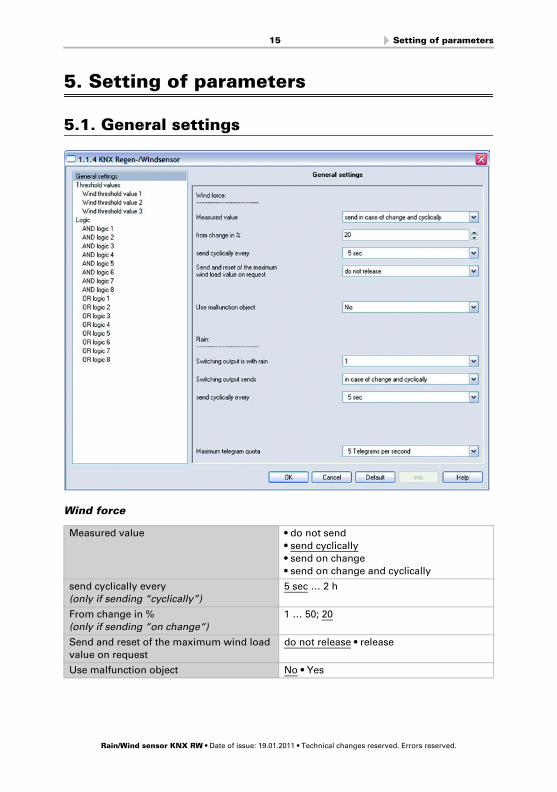
5.1. General settings
Wind force
Measured value • do not send
• send cyclically
• send on change
• send on change and cyclically
send cyclically every
(only if sending “cyclically”)
5 sec … 2 h
From change in %
(only if sending “on change“)
1 … 50; 20
Send and reset of the maximum wind load
value on request
do not release • release
Use malfunction object No • Yes
Rain/Wind sensor KNX RW • Date of issue: 19.01.2011 • Technical changes reserved. Errors reserved.
16 Setting of parameters
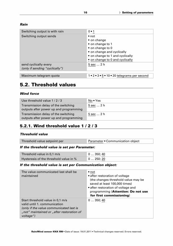
Rain
5.2. Threshold values
Wind force
5.2.1. Wind threshold value 1 / 2 / 3
Threshold value
If the threshold value is set per Parameter:
If the threshold value is set per Communication object:
Switching output is with rain 0 • 1
Switching output sends • not
• on change
• on change to 1
• on change to 0
• on change and cyclically
• on change to 1 and cyclically
• on change to 0 and cyclically
send cyclically every
(only if sending “cyclically”)
5 sec … 2 h
Maximum telegram quota 1 • 2 • 3 • 5 • 10 • 20 telegrams per second
Use threshold value 1 / 2 / 3 No • Yes
Transmission delay of the switching
outputs after power up and programming
5 sec … 2 h
Transmission delay of the switching
outputs after power up and programming
5 sec … 2 h
Threshold value setpoint per Parameter • Communication object
Threshold value in 0,1 m/s 0 … 350; 40
Hysteresis of the threshold value in % 0 … 250; 20
The value communicated last shall be
maintained
• not
• after restoration of voltage
(the changes threshold value may be
saved at least 100,000 times)
• after restoration of voltage and
programming (Attention: Do not use
for first commissioning)
Start threshold value in 0,1 m/s
valid until 1. communication
(only if the value communicated last is
„not“ maintained or „after restoration of
voltage“)
0 … 350; 40
Rain/Wind sensor KNX RW • Date of issue: 19.01.2011 • Technical changes reserved. Errors reserved.

17 Setting of parameters
Switching output
Blocking
„Blocking“ only appears if using „Switching output sends on change“
If block of the switching output is used:
Type of threshold change • Absolute value with a 16 bit
communication object
• Increment / decrement with one
communication object
• Increment / decrement with two
communication objects
Step size
(only if sending „Increment/decrement“)
0,1 m/s … 5 m/s; 1 m/s
Hysteresis of the threshold value in % 0 … 250; 20
Output is at
(TV = Threshold Value)
• TV above = 1 | TV - Hyst. below = 0
• TV above = 0 | TV - Hyst. below= 1
• TV below = 1 | TV + Hyst. above = 0
• TV below = 0 | TV + Hyst. above = 1
Switching delay from 0 to 1 none • 1 sec … 2 h
Switching delay from 1 to 0 none • 1 sec … 2 h
Switching output sends • not
• on change
• on change to 1
• on change to 0
• on change and periodically
• on change to 1 and periodically
• on change to 0 and periodically
send periodically all
(only if sending “periodically“)
5 sec … 2 h
Use block of the switching output Yes • No
Use block of the switching output Yes
Evaluation of the blocking object • if value 1: block | if value 0: release
• if value 0: block | if value 1: release
Value of the blocking object before
1. communication
0 • 1
Behaviour of the switching output
with blocking
• do not send telegram
• send 0
• send 1
Behaviour of the switching output
with release (Auswahl je nach vorheriger
Einstellung möglich)
• do not send telegram
• send status of the switching output
• if switching output = 1 => send 1
• if switching output = 0 => send 0
Rain/Wind sensor KNX RW • Date of issue: 19.01.2011 • Technical changes reserved. Errors reserved.
18 Setting of parameters
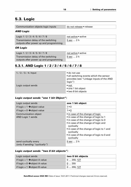
5.3. Logic
AND Logic
OR Logic
5.3.1. AND Logic 1 / 2 / 3 / 4 / 5 / 6 / 7 / 8
Logic output sends “one 1 bit Object“:
Logic output sends “two 8 bit objects“:
Communication objects logic inputs do not release • release
Logic 1 / 2 / 3 / 4 / 5 / 6 / 7 / 8 not active • active
Transmission delay of the switching
outputs after power up and programming
5 sec … 2 h
Logic 1 / 2 / 3 / 4 / 5 / 6 / 7 / 8 not active • active
Transmission delay of the switching
outputs after power up and programming
5 sec … 2 h
1. / 2. / 3. / 4. Input • do not use
• all switching events which the sensor
provides (see “Linkage inputs of the AND
logic”)
Logic output sends • not
• one 1 bit object
• two 8 bit objects
Logic output sends one 1 bit object
if logic = 1 object value 1 • 0
if logic = 0 object value 1 • 0
Communication object
AND Logic 1 sends
• in case of the change of logic
• in case of the change of logic to 1
• in case of the change of logic to 0
• in case of the change of logic and
cyclically
• in case of the change of logic to 1 and
cyclically
• in case of the change of logic to 0 and
cyclically
send cyclically every
(only if sending “cyclically”)
5 sec … 2 h
Logic output sends two 8 bit objects
if logic = 1 object A value 0 … 255; 127
if logic = 0 object A value 0 … 255
if logic = 1 object B value 0 … 255; 127
Rain/Wind sensor KNX RW • Date of issue: 19.01.2011 • Technical changes reserved. Errors reserved.
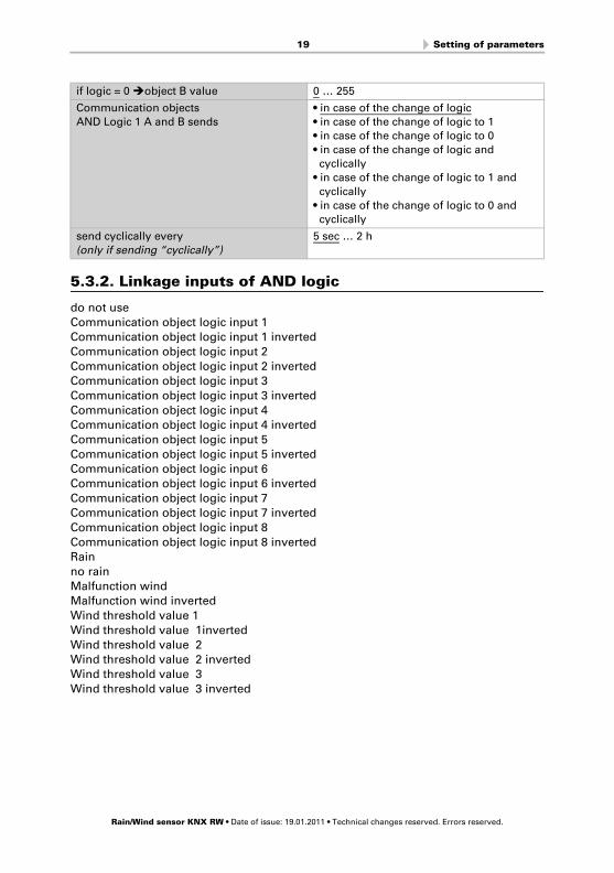
19 Setting of parameters
5.3.2. Linkage inputs of AND logic
do not use
Communication object logic input 1Communication object logic input 1 inverted
Communication object logic input 2
Communication object logic input 2 invertedCommunication object logic input 3
Communication object logic input 3 inverted
Communication object logic input 4Communication object logic input 4 inverted
Communication object logic input 5
Communication object logic input 5 invertedCommunication object logic input 6
Communication object logic input 6 inverted
Communication object logic input 7Communication object logic input 7 inverted
Communication object logic input 8
Communication object logic input 8 invertedRain
no rain
Malfunction windMalfunction wind inverted
Wind threshold value 1
Wind threshold value 1inverted
Wind threshold value 2Wind threshold value 2 inverted
Wind threshold value 3
Wind threshold value 3 inverted
if logic = 0 object B value 0 … 255
Communication objects
AND Logic 1 A and B sends
• in case of the change of logic
• in case of the change of logic to 1
• in case of the change of logic to 0
• in case of the change of logic and
cyclically
• in case of the change of logic to 1 and
cyclically
• in case of the change of logic to 0 and
cyclically
send cyclically every
(only if sending “cyclically”)
5 sec … 2 h
Rain/Wind sensor KNX RW • Date of issue: 19.01.2011 • Technical changes reserved. Errors reserved.
20 Setting of parameters
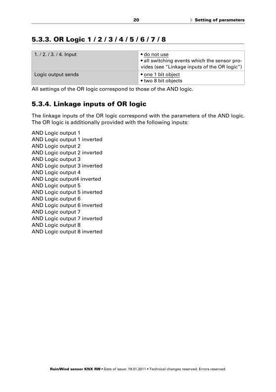
5.3.3. OR Logic 1 / 2 / 3 / 4 / 5 / 6 / 7 / 8
All settings of the OR logic correspond to those of the AND logic.
5.3.4. Linkage inputs of OR logic
The linkage inputs of the OR logic correspond with the parameters of the AND logic.
The OR logic is additionally provided with the following inputs:
AND Logic output 1AND Logic output 1 inverted
AND Logic output 2
AND Logic output 2 invertedAND Logic output 3
AND Logic output 3 inverted
AND Logic output 4
AND Logic output4 invertedAND Logic output 5
AND Logic output 5 inverted
AND Logic output 6AND Logic output 6 inverted
AND Logic output 7
AND Logic output 7 invertedAND Logic output 8
AND Logic output 8 inverted
1. / 2. / 3. / 4. Input • do not use
• all switching events which the sensor pro-
vides (see “Linkage inputs of the OR logic”)
Logic output sends • one 1 bit object
• two 8 bit objects
Rain/Wind sensor KNX RW • Date of issue: 19.01.2011 • Technical changes reserved. Errors reserved.

WS1 ColorControl System for Buildings and for Conservatories
Installation and Operation
EN
WS1000 ColorControl System for Buildings and for Conservatories
Elsner Elektronik GmbH Control and Automation TechnologyHerdweg 7D – 75391 Gechingen Phone +49 (0) 70 56 / 93 97-0 [email protected] Fax +49 (0) 70 56 / 93 97-20 www.elsner-elektronik.de