enclosure 1 to tn e-37268 calculation package number tn-lc ... · this calculation qualifies the...
TRANSCRIPT

Enclosure 1 to TN E-37268
Calculation Package Number TN-LC-0204,Revision 2
FOR INFORMATION ONLYControlled by TN-LC Transportation Package SAR,
Rev. 7, Oct. 2013, Docket 71-9358
CONTROLLED COPY 1-01UNCONTROLLED IF PRINTED
A Form 3.2-1 Calculation No.: TN-LC-0204AR EVA Calculation Cover Sheet Revision No.: 2
TRANSNUCLEAR INC. TIP 3.2 (Revision 6) Page: 1 of 34
DCR NO (if applicable) 165200-021 R2 PROJECT NAME: TN-LC Transport Packaging
PROJECT NO: 65200 CLIENT: Trananuclear, Inc.
CALCULATION TITLE:
TN-LC TRANSPORT CASK TRUNNION, TRUNNION LOCAL STRESS AND TIE DOWNSYSTEM EVALUATIONS.
I
SUMMARY DESCRIPTION:
1) Calculation Summary
This calculation analyzes the stresses In the cask trunnions and In the tie down system for liftingloads during transport conditions.
2) Storage Media Description
Secure network server Initially, then redundant tape backup
It original Issue, Is licensing review per TIP 3.5 required?
Yes El No [0 (explain below) Licensing Review No.: LR
N/ASoftware Utilized: Version:
None N/A
Calculation is complete-
Originator Name and Signature: Mark Tung Date:Calculation has been checked for consistency, completeness and correctness:
Checker Name and Signature: Jeff Peper Date:
Calculation Is approved for use:
Da te:6Date:Prolect Engineer Name and Sinnatur:r Olivier Gandou
iI
1I

A Calculation No.: TN-LC-0204AREVA Calculation Revision No.: 2
TRANSNUCLEAR INC. Page: 2of34
REVISION SUMMARY
AFFECTED AFFECTEDREV. DATE DESCRIPTION PAGES DISKS
0 09/27/10 Initial Issue All All
Changed material of the trunnion andincreased diameter of trunnion shoulder;revised evaluation of trunnion shoulder,trunnion bolts and attachment blocks;
1 04/19/12 corrected allowable for the shear key weld; All ) Allrevised calculation of shear key areabearing area and bearing stress; clarifiedexplanations, modified sketches and addednew ones. The changes are prompted byDCR 65200-006.
Note 1: Due to an extensive amount of changes in Revision 1, including section structure ofthe document, the detail location of changes is not tracked by means of revision bars.
Modified trunnion attachment block weldsper DCR 65200-021 R2. Updated and 1-5, 7-10, 14,
2 0-•/ik6 ,3 clarified weld analysis methodology. Minor 15, 20-25, 28, Alleditorial changes, updated references, and 32-34
number corrections.
A Calculation No.: TN-LC-0204AREVA Calculation Revision No.: 2
TRANSNUCLEAR INC. Page: 3of34
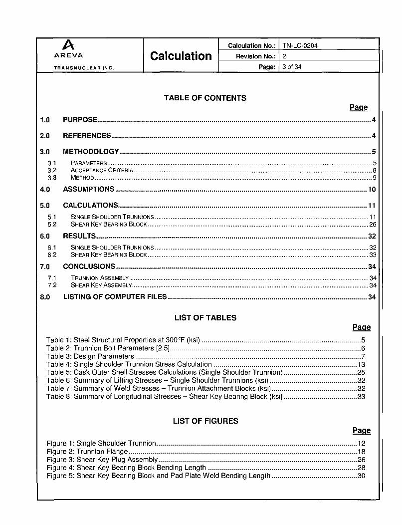
TABLE OF CONTENTS
Page
1.0 PURPOSERENC .................................................................................................................................. 4
2.0 REFERENCES. .............................................................................................................................. 4
3.0 M ETHODOLOGY ..... ......................................................................................................................... 53.1 PARAMETERS ........ ....................................................................................................................................... 53.2 ACCEPTANCE CRITERIA. ....................................................................................................................................... 83.3 METHOD ......................................................................................................................................... 9
4.0 ASSUM PTTIONS ............................................................................................................................. 10
5.0 CALCULATIONSU ............................................................................................................................. 115.1 SINGLE SHOULDER TRUNNIONS ......................................................................................................................... 115.2 SHEAR KEY BEARING BLOCK......................................................................................................................6... 2
6.0 RESULTS TRUNNIO.......... ................................................................................................................. 326.1 SINGLE SHOULDER TRUNNIONS ......................................................................................................................... 326.2 SHEAR KEY BEARING BLOCK ................................................................................................................. ... 33
7.0 CONCLUSIONS ........................................................................................... 347.1 TRUNNION ASSEMBLY ....................................................................................................................................... 347.2 SHEAR KEY ASSEMBLY ...................................................................................................................................... 34
8.0 LISTING O F COM PUTER FILES ............................................................................................... 34
LIST OF TABLESPaqe
Table 1: Steel Structural Properties at 300OF (ksi) ................................................................................ 5Table 2: Trunnion Bolt Param eters [2.5] ........................................................................................... 6Table 3: Design Param eters ......................................................................................................... 7Table 4: Single Shoulder Trunnion Stress Calculation ................................................................... 13Table 5: Cask O uter Shell Stresses Calculations (Single Shoulder Trunnion) ................................. 25Table 6: Sum m ary of Lifting Stresses - Single Shoulder Trunnions (ksi) ........................................ 32Table 7: Sum m ary of W eld Stresses - Trunnion Attachm ent Blocks (ksi) ...................................... 32Table 8: Summary of Longitudinal Stresses - Shear Key Bearing Block (ksi) ................................. 33
LIST OF FIGURESPage
Figure 1: Single Shoulder Trunnion ............................................................................................... 12Figure 2: Trunnion Flange ................................................................................................................... 18Figure 3: Shear Key Plug Assem bly ............................................................................................... 26Figure 4: Shear Key Bearing Block Bending Length ..................................................................... 28Figure 5: Shear Key Bearing Block and Pad Plate W eld Bending Length ...................................... 30

A Calculation No.: TN-LC-0204AREVA Calculation Revision No.: 2
TRANSNUCLEAR INC. Page: 4of34
1.0 PURPOSE
This calculation qualifies the TN-LC cask trunnions design, trunnion bolts, trunnionattachment blocks and their welds for lifting the TN-LC package during transport, andcalculates pertinent stresses in the cask outer shell in the vicinity of the trunnionattachment blocks due to lifting loads. It also evaluates the stresses in the shear keybearing block, pad plate, and welds during transport conditions.
2.0 REFERENCES
2.1 TN Document 65200.0101, Rev.4 "Design Criteria Document (DCD) for the TN-LCTransport Package."
2.2 "Pressure Vessel Design Handbook", Second Edition, Henry Bednar, 1986.
2.3 TNLC-0401 Rev. 0, "Thermal Analysis of TN-LC Transport Cask for NormalConditions of Transport."
2.4 TNLC-0200 Rev. 1, "Transport Packaging Weight, CG location and moment of inertiacalculation."
2.5 Machinery Handbook, 26th Edition, Industrial Press, 2000.
2.6 1 0CFR Part 71, "Packaging and Transportation of Radioactive Materials."
2.7 ANSI N14.6, "American National Standard for Radioactive Materials - Special LiftingDevices for Shipping Containers Weighing 10,000 Pounds (4500 kg) or More", 1993.
2.8 Machine Design, August 17, 1967, "Eccentrically Loaded Joints", Richard T. Burger.
2.9 WRC Bulletin 107, March 1979 Revision, "Local Stresses in Spherical and CylindricalShells Due to External Loading."
2.10 NUREG/CR 6007, "Stress Analysis of Closure Bolts for Shipping Casks," LawrenceLivermore National Laboratory, 1992.
2.11 ASME Boiler and Pressure Vessel Code, Section III, Subsection NF, 2004 including2006 addenda.
A Calculation No.: TN-LC-0204AREVA Calculation Revision No.: 2
TRANSNUCLEAR INC. Page: 5of34
3.0 METHODOLOGY
3.1 Parameters
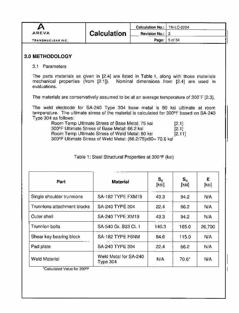
The parts materials as given in [2.4] are listed in Table 1, along with those materialsmechanical properties (from [2.1]). Nominal dimensions from [2.4] are used inevaluations.
The materials are conservatively assumed to be at an average temperature of 300'F [2.3].
The weld electrode for SA-240 Type 304 base metal is 80 ksi ultimate at roomtemperature. The ultimate stress of the material is calculated for 30O0-F based on SA-240Type 304 as follows:
Room Temp Ultimate Stress of Base Metal: 75 ksi [2.1]300-°F Ultimate Stress of Base Metal: 66.2 ksi [2.1]Room Temp Ultimate Stress of Weld Metal: 80 ksi [2.11]30O0-F Ultimate Stress of Weld Metal: (66.2/75)x80= 70.6 ksi
Table 1: Steel Structural Properties at 300OF (ksi)
Part Material Sy Su E
[ksi] [ksi] [ksi]
Single shoulder trunnions SA-1 82 TYPE FXM1 9 43.3 94.2 N/A
Trunnions attachment blocks SA-240 TYPE 304 22.4 66.2 N/A
Outer shell SA-240 TYPE XM19 43.3 94.2 N/A
Trunnion bolts SA-540 Gr. B23 Cl. 1 140.3 165.0 26,700
Shear key bearing block SA-182 TYPE F6NM 84.6 115.0 N/A
Pad plate SA-240 TYPE 304 22.4 66.2 N/A
Weld Material Weld Metal for SA-240 N/A 70.6* N/AType 304
*Calculated Value for 300-F
A Calculation No.: TN-LC-0204AREVA Calculation Revision No.: 2
TRANSNUCLEAR INC. Page: 6of34
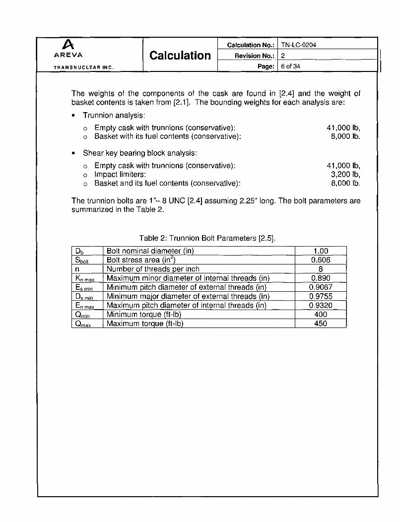
The weights of the components of the cask are found in [2.4] and the weight of
basket contents is taken from [2.1]. The bounding weights for each analysis are:
0 Trunnion analysis:
" Empty cask with trunnions (conservative):o Basket with its fuel contents (conservative):
Shear key bearing block analysis:
41,000 Ib,8,000 lb.
41,000 Ib,3,200 Ib,8,000 lb.
0
0
0
Empty cask with trunnions (conservative):Impact limiters:Basket and its fuel contents (conservative):
The trunnion bolts are 1"- 8 UNC [2.4] assuming 2.25" long. The bolt parameters aresummarized in the Table 2.
Table 2: Trunnion Bolt Parameters [2.5].
Db Bolt nominal diameter (in) 1.00Sbolt Bolt stress area (in;ý) 0.606n Number of threads per inch 8Kn max Maximum minor diameter of internal threads (in) 0.890Es min Minimum pitch diameter of external threads (in) 0.9067Ds min Minimum major diameter of external threads (in) 0.9755En max Maximum pitch diameter of internal threads (in) 0.9320Q0nm Minimum torque (ft-lb) 400Qmax Maximum torque (ft-lb) 450

A Calculation No.: TN-LC-0204
AREVA Calculation Revision No.: 2
TRANSNUCLEAR INC. Page: 7of34
Table 3: Design Parameters
Ntr Number of trunnions 2a, Vertical acceleration (g) 6aL Longitudinal acceleration (g) 10Thos Outer shell thickness (in) 1.5Nb Number of bolts per trunnion 8K Nut factor for trunnion bolts 0.135Dbolt Bolt circle diameter (in) 6.875Thtooi Thickness of lifting tool (in) 1.00Dextl Diameter of trunnion shoulder (in) 4.25Lsh Length of trunnion shoulder (in) 2.25Lhub Length of trunnion hub (in) 2.69Dhub Diameter of trunnion hub (in) 4.00Dhole Diameter of trunnion bolt counterbore (in) 1.8Dmax Maximum outer diameter of trunnion (in) 9.50Thflanqe Thickness of flange at closure bolt cylinder (in) 1.75Roý Outer radius of the outer shell (in) 15Thw ext Thickness of the attachment block external weld (in) 0.75Thw int Thickness of the attachment block internal weld (in) 0.00Dw int Diameter of the attachment block internal weld (in) 4.010Dw ext Length of the side of the attachment block external weld (in) 10.5Dab Outer surface diameter of the attachment block (in) 38.5Hab Depth of the counterbore for trunnion in the attachment block (in) 0.77ac Angle of shear key plug assembly chamfer (degrees) 18Ask Distance between shear key top surface and thermal shield shell (in) 0.37Hss Height of shear key bearing block (in) 4.25b Width of the base of the shear key bearing block (in) 13.62d Longitudinal dimension of the shear key bearing block (in) 9.62Thss Thickness of shear key bearing block wall (in) 2.75Thpp Thickness of pad plate (in) 1.0bpp Longitudinal dimension of pad plate (in) 28.00dpp Lateral dimension of pad plate (in) 21.21at Coefficient of thermal expansion of trunnions at 300 OF (in/in/°F) 8.7 x 10⁶ab Coefficient of thermal expansion of trunnion bolts at 300 OF (in/in/°F) 6.9 x 10T Analysis temperature (OF) 300
A Calculation No.: TN-LC-0204AREVA Calculation Revision No.: 2
TRANSNUCLEAR INC. Page: 8of34
3.2 Acceptance Criteria
3.2.1 Trunnions
The TN-LC transport cask is lifted by the upper two removable trunnions. Thetrunnion attachment blocks are welded to the cask structural shell and as suchare considered a structural part of the package. The removable trunnionbodies, although designed per subsection NF of the ASME code, are notstructural part of the transportation package and are evaluated per therequirements of 1 0CFR71.45 [2.6]. The trunnions are designed and fabricatedbased on ANSI N 14.6 [2.71.
In addition, the package must be designed such that "failure of any liftingdevice under excessive load would not impair the ability of the package to meetthe requirements" of [2.6].
Single Shoulder Trunnions:
For 6 g loads, the stresses must remain below Sy. For 10 g loads, the stressesmust remain below the ultimate strength Su. [2.1]
3.2.2 Shear Key Bearing Block
10CFR71.45 (b) (1) requires that a system of tie-down devices that is astructural part of the package must be capable of withstanding, withoutgenerating stress in any material of the package in excess of its yield strength,a static force applied to the center of gravity of the package having a horizontalcomponent along the direction in which the vehicle travels of 10 times theweight of the package with its contents.
Therefore, for 10 g loads, the stresses must remain below Sy (or 0.6 x Sy in thecase of shear stress). The stresses for the weld between the outer shell andpad must be lower than 0.6xSy of the weakest base material.
3.2.3 Margin of Safety
It will be calculated as follows:
Margin = Allowable stressMargine st 1.Calculated stress
The margin should always be positive.
A Calculation No.: TN-LC-0204AREVA Calculation Revision No.: 2
TRANSNUCLEAR INC. Page: 9of34
3.2.4 Weld Analysis
Per Table NF-3324.5(a)-1 [2.11], tension normal to the axis on the effectivethroat of a partial penetration groove weld is limited to 0.3*Su, and shear stresson the base metal is limited to 0.4*Sy.
ASME Subsection NF-3322.1 [2.11] limits the maximum tensile stress instructural steel to 0.6*Sy and 0.5*Su, and limits the shear stress to 0.4*Sy.Therefore, per ASME NF, the weld metal allowable tensile stress is a factor of(0.5/0.3)=1.67 less than the base metal stress.
Therefore, the ANSI N1 4.6 stress criteria for weld evaluations are as follows:
Allowable base metal tension: Lesser of (Sy/6) and (Su/1 0)Allowable base metal shear stress: (0.4/0.6)x[Lesser of (Sy/6) and (Su/1 0)]Allowable weld metal stress intensity: (0.3/0.5)x(Su/1 0)
For XM-19 Material: Sy/6 = 7.22 and Su/10 = 9.42. Therefore, yield stressgoverns and the weld base metal tension will be evaluated based on 6x thelifted load, compared against yield stress. Base metal shear will be checkedbased on (0.6/0.4)*6 = 9x the lifted load, compared against yield stress of thebase metal.
For SA-240 Type 304 material: Sy/6 = 3.73 and Su/10 = 6.62. Therefore, yieldstress governs and the base metal tension will be evaluated based on 6x thelifted load, compared against yield stress. Base metal shear will be checkedbased on (0.6/0.4)*6 = 9x the lifted load, compared against yield stress of thebase metal.
Weld metal stress intensity will be evaluated based on (0.5/0.3)*10 = 16.67xthe lifted load, compared against the ultimate stress of the weld metal.
3.3 Method
3.3.1 Trunnions Evaluation
First, the stresses in various sections of the trunnions are calculated. Then,the trunnion bolts are evaluated. Stresses in the trunnion flange and in thewelds of the trunnion attachment block are also analyzed. Finally, the localstresses in the cask outer shell at the trunnion attachment block are calculated.
.3.3.2 Shear Key Bearing Block Evaluation
The shear key bearing block and pad plate are parts of the cask structuredesigned to resist the 10 g longitudinal transportation load. The shear key

A Calculation No.: TN-LC-0204AREVA Calculation Revision No.: 2
TRANSNUCLEAR INC. Page: 10of34
bearing block is a welded structure. The 21.21" x 28" x 1" pad plate is used tospread the longitudinal shear load over a large area of the cask structural shellto which it is welded, thus preventing the cask outer shell to be subjected toany bending moment resulting from the longitudinal load.
First the bearing stress between the shear key and the shear key bearing blockis calculated. Bending stresses in the shear key bearing block are evaluatedas well. Finally, the welds between the shear key bearing block and the padplate and between the pad plate and the cask outer shell are analyzed.
4.0 ASSUMPTIONS
A Dynamic Load Factor (DLF) of 1.15 is used for the lifting loads.
The maximum weight of the packaging contents is conservatively taken as 8,000 lb [2.4].
The section of the shear key bearing block perpendicular to the cask axis, which is acircular sector, is conservatively assumed to bend like a straight beam.
The reference temperature is 70 0F.
The ultimate stress of weld material at 30O°F is calculated based on the reduction inultimate strength of A240 Type 304 base metal for 300°-F. Calculations are performed inmaterial property section of analysis.
A Calculation No.: TN-LC-0204AREVA Calculation Revision No.: 2
TRANSNUCLEAR INC. Page: 11 of 34
5.0 CALCULATIONS
5.1 Single Shoulder Trunnions
5.1.1 Lifting load
The TN-LC transport cask is lifted from the fuel pool vertically by its upper tworemovable trunnions using the fuel building crane. The weights of itscomponents are: [2.4]
" Empty cask with trunnions: maximum 41,000 lb.
* Basket with its fuel contents: maximum 8,000 lb.
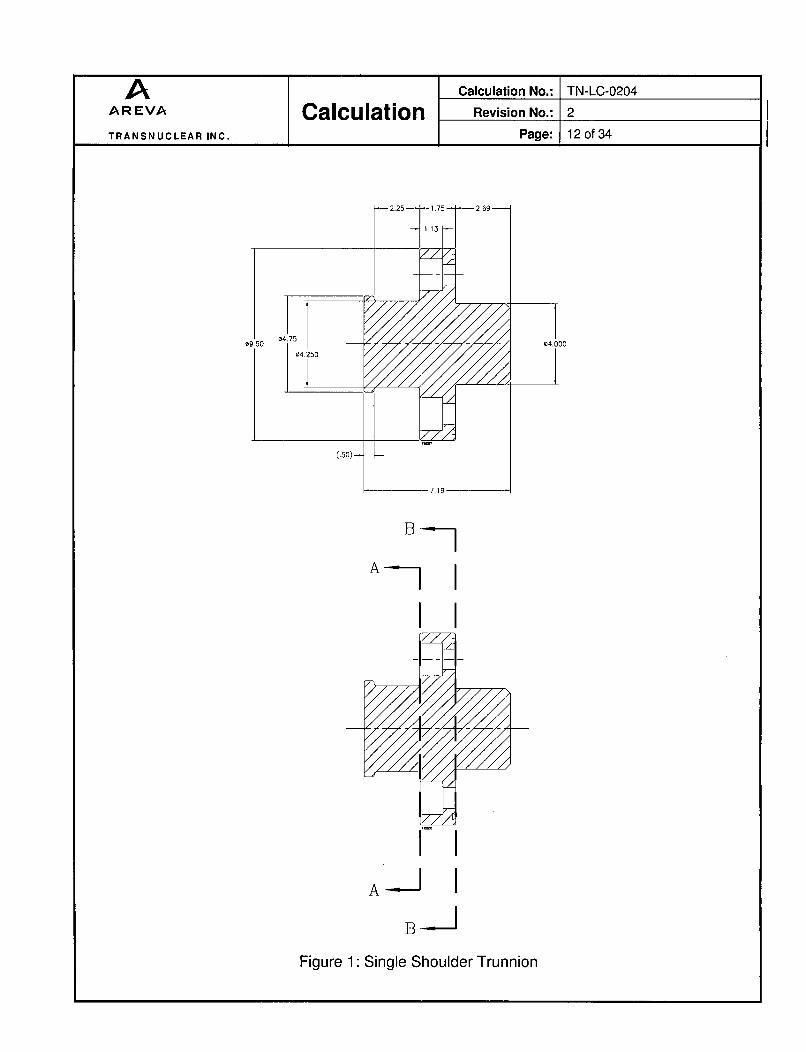
The maximum weight of the cask is WL = 49,000 lb for the vertical lift from thefuel pool, distributed evenly between the two upper trunnions. Using a dynamicload factor of 1.15 and a lifting load of 6 g, the vertical design load (yield) forone trunnion is:
6F11 = WL x DLFx = 49,000 x 1.15 x - = 169,050 lb.N,, 2
Trunnion section is shown on Figure 1.
A Calculation No.: TN-LC-0204
AREVA Calculation Revision No.: 2
TRANSNUCLEAR INC. Page: 12of34
A I
I IA-JI
B-b
Figure 1: Single Shoulder Trunnion

A Calculation No.: TN-LC-0204AREVA Calculation Revision No.: 2
TRANSNUCLEAR INC. Page: 13of34
5.1.2 Trunnion stresses
The stresses in sections A-A and B-B of the trunnion, shown in Figure 1, arecalculated in Table 4.
Table 4: Single Shoulder Trunnion Stress Calculation
Section A-A B-B
SAM = - e(xt,) sB8 =-(D,,,)Stress area (in2)
' (4.25 2)= 14.19 4 (4.02) 12.574 4
64
Bending distance (in) LAA = Lsh -- Thtool= 2.25 - 1 = 1.25
MAA = Fv x LAABending moment (in.lb) = 169,050 x 1.25
= 211,312.50
F1, 169,050 F1, 169,050Shear stress (ksi) SAA 14.19 SBB 12.57
= 11.91 -13.45MAz X Devi_
IAA ?
Bending stress (ksi) 211,312.5 4.25
16.01 2= 28.04
Max. stress intensity (ksi) V28.042 +4x] 1.91 2 2x13.45= 26.90= 36.80

A Calculation No.: TN-LC-0204AREVA Calculation Revision No.: 2
TRANSNUCLEAR INC. Page: 14of34
5.1.3 Trunnion Bolt Stress Evaluation
5.1.3.1 Load Due to Trunnion Moment
The trunnions are attached to the cask using eight 1"- 8 UNC bolts.The bolts are in tension because of the moment on the trunnionflange. The shear load is supported by trunnion hub and the hole inthe trunnion (welded to the cask body) attachment block. The radialclearance between the screw heads (and shanks) and the trunnionflange holes is large enough so that the shear load is supported by thetrunnion hub-to-block hole interface by bearing, and not by the bolts.
The bending length is equal to (section BB is shown in Figure 1):
LBB = Lsh + Thflange - Thtoo, = 2.25 + 1.75 - 1.0 = 3.0 in.
Therefore, the bending moment MBB is equal to MBB = Fv x LBB,
which is equal to:
MBB = 169,050 x 3 = 507,150 in.-lb.
According to [2.8], case 4, for bolt patterns symmetrical about thevertical axis and flange rotating about the bottom bolt, the maximumbolt force Fm due to the bending moment MBB is:
[ 2 + Cos-E-- 1 MBBL3xDbolt /2xNb, Nbi I
4 ++cosj x507,1503 x6.875 x8 8
23,653.22 lb.
5.1.3.2 Bolt Preload
Per [2.4], the trunnion bolts should be torqued at the torque range from400 ft-lb to 450 ft-lb.
Bolt preload for minimum torque (Omin) is:
Q,,,i 400 x 12P,,i= - - = 35555.6 lb.
KxDb 0.135xl
Bolt preload for maximum torque (Qmax) is:
A Calculation No.: TN-LC-0204AREVA Calculation Revision No.: 2
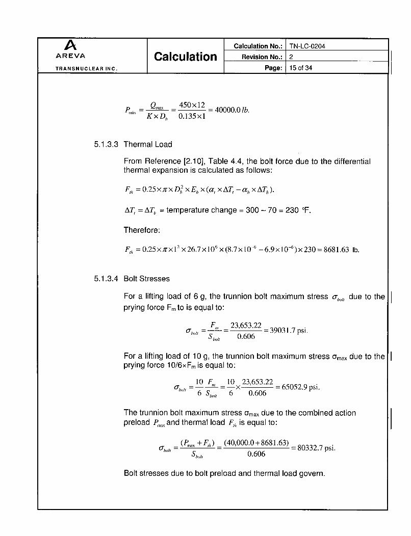
TRANSNUCLEAR INC. Page: 15 of 34
p,,,_ 450_ 4x12 = 40000.0 lb.KxDb 0.135x1
5.1.3.3 Thermal Load
From Reference [2.10], Table 4.4, the bolt force due to the differentialthermal expansion is calculated as follows:
F,, =0.25xx D 2 xEbx(axAT, -cbxATb).
AT, = ATb = temperature change = 300 - 70 = 230 OF.
Therefore:
F,h = 0.25 XfX1 2 x 26.7 x 106 x (8.7 x 10- 6 - 6.9 x 10-6) x 230 = 8681.63 lb.
5.1.3.4 Bolt Stresses
For a lifting load of 6 g, the trunnion bolt maximum stress abo,- due to theprying force Fm to is equal to:
F,, 23,653.22O'bot -- -101- 0.6 6 - 39031.7 psi.S bo ot, 0.606
For a lifting load of 10 g, the trunnion bolt maximum stress Gmax due to theprying force 10/6xFm is equal to:
10 F,, 10 23,653.22='bo "!- - X - 65052.9 psi.
6 Sboo, 6 0.606
The trunnion bolt maximum stress Umax due to the combined actionpreload I,,,ax and thermal load F,,, is equal to:
= (Pmax + F,,) (40,000.0 + 8681.63) = 80332.7 psi.Sbult 0.606
Bolt stresses due to bolt preload and thermal load govern.

A Calculation No.: TN-LC-0204
AREVA Calculation Revision No.: 2
TRANSNUCLEAR INC. Page: 16of34
5.1.3.5 Minimum Engagement Length
The minimum engagement length Le for the bolt and flange is (seeRef. [2.5], page 1490):
2 x Sbo otLe =XbI
3.116 K, maxx l+. 5 7 7 35xnXkEsmm nK ....
-2 x 0.606
3.1416x 0.89Ox 12 + .57735 x 8 x (0.9067 - 0.890)1
Le = 0.751 in
According to [2.5], page 1490:
J As x Sue
A, x Sui
Sue is the tensile strength of external thread material, equal to 165 ksi,and Sui is the tensile strength of internal thread material, equal to66.2 ksi.
A, is the shear area of external threads:1
As = 3.1416 x nx Le XKn max X-L+0.57735x(Esmin -Knmax)[2n
An is the shear area of internal threads:
An =3.1416xnxLe xDsmin x1n +0.57735x(Dsmin- Enmax)]
Therefore:
A, =3.1416x8x0.751x0.890x + 0.57735 x (0.9067 - 0.890)12x8
A, =1.212in2 .
A,, = 3.1416x8x 0.751 x0.9755 x E + 0.57735 x(0.9755-0.9320)]12x8J

A Calculation No.: TN-LC-0204
AREVA Calculation Revision No.: 2
TRANSNUCL-AR INC. Page: 17of34
A,, =1.613in 2 .
So:
1.212x165 -1.872.1.613x 66.2
Therefore, the minimum required engagement lengthQ=J x Le =1.872 x 0.751 = 1.41 in.
According to [2.4], helicoils 1185-16CN-3000 of maximum length3.0 in. are used with bolts of maximum threaded length1.63 in = 2.25 in (total bolt shank length) - 1.75 in (trunnion flangethickness) + 1.13 in (counter bore depth). The helicoils are cut to fitwith the maximum threaded length of the bolt which is 1.63 in.

A Calculation No.: TN-LC-0204AREVA Calculation Revision No.: 2
TRANSNUCLEAR INC. Page: 18of34
5.1.4 Trunnion Flange Stresses
The trunnion flange is shown in Figure 2
L
_22.5"-
A A
Lf, =1.O5"-
TRUNNION
L
SECTION A-A
Figure 2: Trunnion Flange
A Calculation No.: TN-LC-0204AREVA Calculation Revision No.: 2
TRANSNUCLEAR INC. Page: 19of34
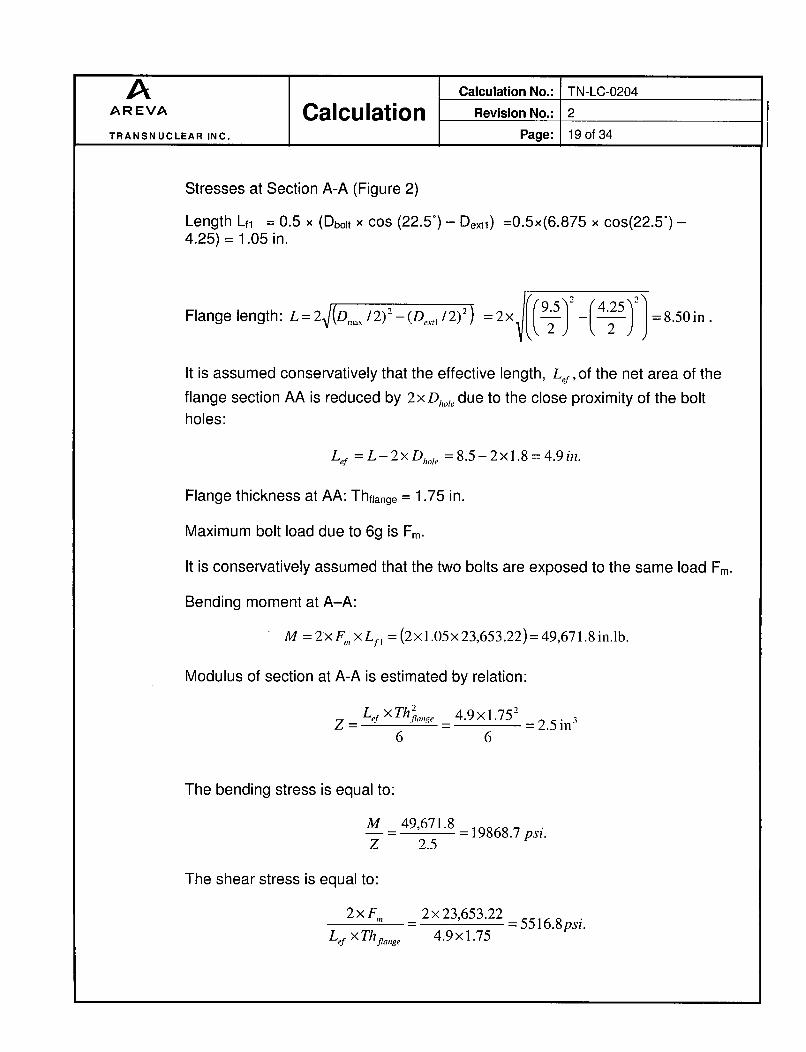
Stresses at Section A-A (Figure 2)
Length Lfj = 0.5 x (Dbolt x cos (22.5°) - Dexu) =0.5x(6.875 x cos(22.5°) -4.25) = 1.05 in.
Flange length: L = 2V(Dia .,/2)2 - (De,,,/2) 2 = 2x - = 8.50 in.
It is assumed conservatively that the effective length, Lef of the net area of theflange section AA is reduced by 2xDh,,, due to the close proximity of the boltholes:
Lef =L-2xDhole = 8.5-2x1.8=4.9in.
Flange thickness at AA: Thfjange = 1.75 in.
Maximum bolt load due to 6g is Fm.
It is conservatively assumed that the two bolts are exposed to the same load Fm.
Bending moment at A-A:
M =2xF,,xLp = (2x 1.05x 23,653.22) = 49,671.8 in.lb.
Modulus of section at A-A is estimated by relation:
Lef XTh•2 49x1752a = _____ = 2.5
6 6
The bending stress is equal to:
M _49,671.8M 2.596 =19868.7 psi.Z 2.5
The shear stress is equal to:
2xF,,, 2x 23,653.22- = 5516.8psi.
Lef x Thflage 4.9 x 1.75

A Calculation No.: TN-LC-0204
AREVA Calculation Revision No.: 2
TRANSNUCLEAR INC. Page: 20 of 34
The maximum stress intensity is equal to:
UbO' + 4x r 2 -, F19,868.72 +4x5516.82 = 22726.8 psi.
5.1.5 Trunnion Attachment Block and Cask Shell Weld
There is a 3/4" groove weld on the outer perimeter of the attachment block andthe cask shell [2.4]. On the inside of the attachment block, there is a seal weld.Strength of the seal weld is ignored. The outer weld is subjected to a bendingmoment plus direct shear loading.
Tension in base metal is evaluated for 6x lifted load and compared to Sy.Shear in base metal is evaluated for 9x lifted load and compared to Sy. Weldmetal is evaluated for 16.67x lifted load and compared to Su of weld metal.Refer to Section 3.2.4 for weld loading details.
6x Load for Base Metal Tensile Stress Check: 169,050 lbs9x Load for Base Metal Shear Stress Check: 253,575 lbs16.67x Load for Weld Metal Stress Check: 469,677 lbs
The outer surface diameter of the cask attachment block is 38.5 in. Since theinner radius of the cask shell at attachment block is 15 in, the maximum heightof the block at a distance (10.5/2) = 5.25 inch from the block symmetry planeis:
H = 38 -5.252 - 1521 (5.25)2 =4.47 in.
The minimum height of the block is:
H = -5.252- 152 4.1_.. J =3.65in.
The average height Havg is therefore 0.5 x (4.47+3.65) = 4.06 in.
The bending length for the weld is conservatively calculated using Hmax:
Lsh-Thtooi + Hmax + Thfiange - Hab= 2.25-1.0 + 4.47 + 1.75 - 0.77 = 6.7 in. [2.4]
A Calculation No.: TN-LC-0204AREVA Calculation Revision No.: 2
TRANSNUCLEAR INC. Page: 21 of 34
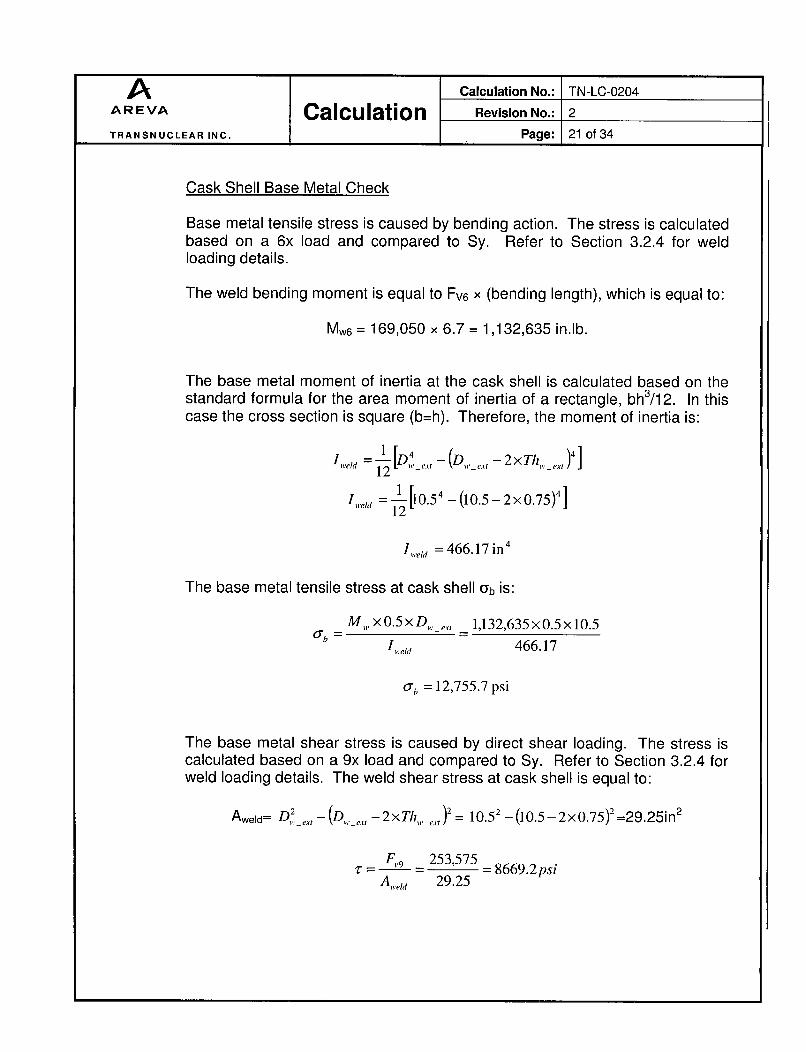
Cask Shell Base Metal Check
Base metal tensile stress is caused by bending action. The stress is calculatedbased on a 6x load and compared to Sy. Refer to Section 3.2.4 for weldloading details.
The weld bending moment is equal to Fv6 x (bending length), which is equal to:
Mw6 = 169,050 x 6.7 = 1,132,635 in.lb.
The base metal moment of inertia at the cask shell is calculated based on thestandard formula for the area moment of inertia of a rectangle, bh 3/12. In thiscase the cross section is square (b=h). Therefore, the moment of inertia is:
,i.eld = II•[D4 _r..- (D ._.,.e -2x T ,e_,, )4]
wed 12 WCI- tA
'welff = [10.5 54 -(10.5-2xO.75)4]
,ie i, = 466.17 in 4
The base metal tensile stress at cask shell Gb is:
M, x0.5xD _, _ 1,132,635xO.5xlO.5
' Itj 466.17
ob = 12,755.7 psi
The base metal shear stress is caused by direct shear loading. The stress iscalculated based on a 9x load and compared to Sy. Refer to Section 3.2.4 forweld loading details. The weld shear stress at cask shell is equal to:
,,., -_2xT , = 2 -(10.5- 2x0.75)2 =29.25in
Fý,9 253,575Aeld 29.25

A Calculation No.: TN-LC-0204AREVA Calculation Revision No.: 2
TRANSNUCLEAR INC. Page: 22ot34
Weld Metal Stress Intensity
Weld metal stress intensity is caused by a combination of bending and shearstresses. The stress is calculated based on a 16.67x load and compared to Suof the weld metal. Refer to Section 3.2.4 for weld loading details.
Therefore, the weld bending moment is equal to Fv16.67 x (bending length),which is equal to:
Mw1 6.67= 469,677 x 6.7 = 3,146,836 in.lb.
The moment of inertia and area of the weld are the same as calculated abovefor base metal. The weld bending stress at trunnion block 0 b is:
SM , 6.67 0.5 x D, , 3,146,836 x 0.5 x 10.5I=weld 466.17
ub= 35,440 psi
The weld metal shear stress is equal to:
F,,16.67 469,677_"_.. . . 16,O57psiAweld 29.25
The maximum weld metal stress intensity is equal to:
o-b-±+ 4 x r2 = f354402+ 4 x 160572 = 4 7,82 6 psi.
Attachment Block Base Metal Check
The attachment block base metal is a 452 groove. The moment of inertia is thesame as calculated previously, but bending action causes a component oftension and a component of shear on the 45Q face. Likewise, the direct shearload causes a component of tension and a component of shear on the 45 0f ace.
The tensile stress component from bending load is calculated based onprevious bending stress. The stress is adjusted for the 45 - weld surface and isreduced by a factor of 1.414 to account for the increased surface area:
A Calculation No.: TN-LC-0204AREVA Calculation Revision No.: 2 '
TRANSNUCLEAR INC. Page: 23 of 34
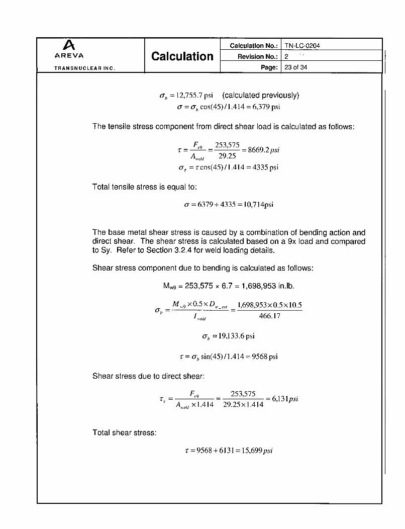
ab =12,755.7 psi (calculated previously)
a = ab cos(45) / 1.414 = 6,379 psi
The tensile stress component from direct shear load is calculated as follows:
F,9 253,575A•" e~ - - 292 =8669.2 psiA,,.eld 29.25
a, = z'cos(45) /1.414 =4335 psi
Total tensile stress is equal to:
cr = 6379+4335 = 10,714psi
The base metal shear stress is caused by a combination of bending action anddirect shear. The shear stress is calculated based on a 9x load and comparedto Sy. Refer to Section 3.2.4 for weld loading details.
Shear stress component due to bending is calculated as follows:
Mw9 = 253,575 x 6.7 = 1,698,953 in.lb.
M W9 x0.5xD,,e,, 1,698,953x0.5x 10.5
lWeId 466.17
ab = 19,133.6 psi
-r = a. sin(45) /1.414 = 9568 psi
Shear stress due to direct shear:
F,,9 253,575 6,131psiA >elx1.414 29.25×1.414
Total shear stress:
v = 9568 + 6131 = 15,699psi
A Calculation No.: TN-LC-0204
AREVA Calculation Revision No.: 2
TRANSNUCLEAR INC. Page: 24of 34
5.1.6 Stress in Trunnion Attachment Block
The shear and bending stress in the attachment block are bounded by theevaluation of the attachment welds.
The bearing stress in the trunnion hub-to-block interface:
F1, 169,050_F, - 16,50 - 15.7 ksi.Li,,,b X Dl,,t, 2,69 x 4.0
5.1.7 Local Stresses in Cask Outer Shell at Trunnion Attachment Block
Local stresses are calculated using the methodology [2.9]. for a squareattachment with circumferential side length equal to 2 x c, and longitudinal sidelength equal to 2 x C2
The trunnion shear loads in the longitudinal and circumferential directions arerespectively VL = Fv = 169,050 lb and Vc = 0 lb.
The bending length is calculated using Have:
Lsh-ThtooI + Have + Thflange - Hab= 2.25-1.0 + 4.06 + 1.75 - 0.77 = 6.29 in. [2.4]
The external overturning moments supported by the intersection in thelongitudinal and circumferential directions with respect to the shell arerespectively:
ML = 169,050 x 6.29 = 1,063,324.5 in.lb. and Mc = 0 in.lb.
The thickness of the outer shell is Thos = 1.5 in. The cylinder mean radius is:
Rm = Ros -0.5 x Thos = 15-0.5xl .5= 14.25 in.

A Calculation No.: TN-LC-0204AREVA Calculation Revision No.: 2
TRANSNUCLEAR INC. Page: 25of34
The block circumferential side length is equal to 2 x c, = 10.50 in. Itsequivalent longitudinal length 2 x c2=10.50 in. since the block shape is square[2.4]
Therefore:c= = c = 5.25 in.
The geometric parameters are:
R, 14.25 c_5.25= 1. = 9.5, 8 = 8, = 632 - - = 0.37.
Tho, 1.5 R,,, 14.25
The above quantities are used as the input data in the supplementaryspreadsheet (file TN-LC-0204-Rev-2.xls, documented in the Section 8.0) tocalculate the stresses in the outer shell of the cask. The spreadsheet layout isdocumented as Table 5.
Table 5: Cask Outer Shell Stresses Calculations (Single Shoulder Trunnion)Abs. stress
From fig.: Read curves for: Mult. values Au Al Bu BI Cu CI Du DI
3C & 4C 0 0 0 0 0 0 0 0 0 0 01C & 2C-1 0 0 0 0 0 0 0 0 0 0 0
3A 0 0 0 0 0 01A 0 0 0 0 0 03B 1.152 P=0.37 9,475 10,916 -10,916 -10,916 16,916 10,916
1B or 1B-1 0.0284 540,101 15,339 -15,339 15,339 15,339 -15,339_(phi - circumferential stresses) -26,255 4,423 26,255 4,423 0 0 0 0
3C & 4C 0 0 0 0 0 0 0 0 0 0 01C-1 &2C 0 0 0 0 0 0 0 0 0 0 0
4A 0 0 0 0 0 02A 0 0 0 0 0 04B 0.414 0=0.37 9,475 3,923 -3,923 -3,923 3,923 3,923
2B or 2B-1 0.0474 540,101 25,601 -25,601 25,601 25,601 -25,601E(X - longitudinal stresses) -29,524 21,678 29,524 -21,678 0 0 0 0
Shear stress due to torsion MT 0 0 0 0 0 0 0 0 0Shear stress due to load Vc 0 0 0 0 0Shear stress due to load VL 5,367 5,367 5,367 5,367 5,367
X(shear stresses T) 0 0 0 0 5,367 5,367 5,367 5,367Stress intensities 29,524 21,678 29,524 21,678 10,733 10,733 10,733 10,733
The maximum stress intensity is 29,524 psi.
The trunnion attachment block and the cask shell are at the sametemperatures.
A Calculation No.: TN-LC-0204AREVA Calculation Revision No.: 2
TRANSNUCLEAR INC. Page: 26 of 34
5.2 Shear Key Bearing Block
5.2.1 Horizontal Load
The TN-LC transport cask is blocked in translation by its shear key. The weightof its elements during transport is:
* Empty cask trunnions(conservative): maximum 41,000 Ib,* Impact limiters (top and bottom): (conservative) maximum 3,200 Ib,* Basket with its fuel contents (conservative): maximum 8,000 lb.
The maximum weight of the cask is WH = 52,200 lb for horizontal loads,
concentrated on the shear key plug assembly (10 g).
5.2.2 Bearing Stress between the Shear Key and the Shear Key Bearing Block
Using a dynamic load factor of 1.15, the horizontal design load (yield) is:
FH = WH X DLF X aL = 52,200 x 1. 15 x 10 = 600,300 1b.
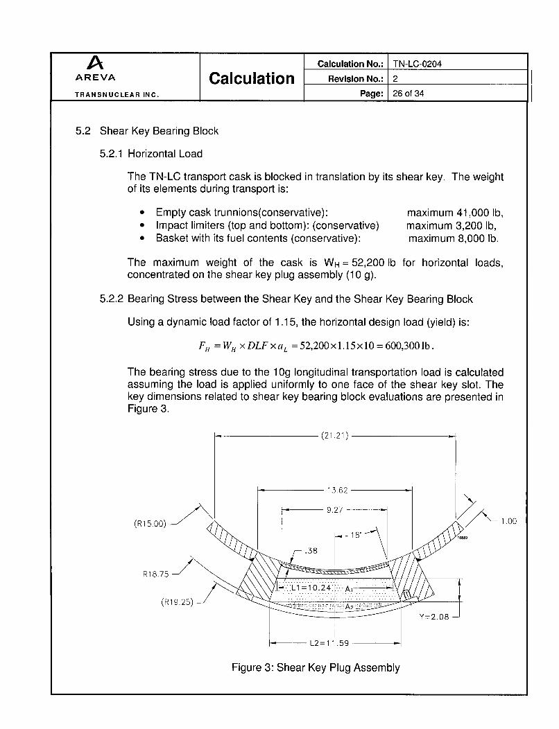
The bearing stress due to the 1Og longitudinal transportation load is calculatedassuming the load is applied uniformly to one face of the shear key slot. Thekey dimensions related to shear key bearing block evaluations are presented inFigure 3.
(21.21)
1-3.62
9.27
-- 1 .0
R18.75-
(R19.25) I ..*..........
Figure 3: Shear Key Plug Assembly
A Calculation No.: TN-LC-0204AREVA Calculation Revision No.: 2
TRANSNUCLEAR INC. Page: 27 of 34
The bearing area is divided into two areas (see Figure 3): a trapezoidal areaA1, of average width (L1+L2)/2 and height Y, and an area A2, which is asegment of solid circle (see Figure 3). The bearing area is the sum of A, andA2. The bearing area A, is calculated as:
A= L1 + LX1 2 xY2
where:
L, is the width of the top surface of the shear key assembly (shear key chamfer topwidth).
L2 is the width of the shear key assembly at the lowest lateral point of the contactwith the shear key bearing block assembly.
Y is the distance between the planes L, and L2.
The angle of shear key assembly chamfer is ac= 180.
From geometrical relations (see Figure 3)
L2= 2x18.75xsin(18 0) =11.59 in.
The analysis assumes that the top surface of shear key is separated from thethermal shield shell component by Ask = 0.37", so that the distance of the shearkey top surface to the TN-LC cask center is 15.0+0.38+0.37 =15.75" (Figure 3).
From the geometric relations of shear key bearing block (see Figure 3):
Y= 1(l 8.75 -15)2 11l.5 9 29 .2 7 )J -[115.75 -15.0Oxcos(I 8')]= 3.566 - 1.484 =2.08
L, = L2- 2xYx tan( ac )=1 1.59-2 x 2.08 x tg(1 8°) = 10.24 in.
Therefore:A•L +L• 10.24+11.59, = x Y= x 2.08 = 22.70 in•2
2 2
The solid circle area A2, with the span angle ac=1 8 0 (0.314 radians) can beassessed by the expression:

A Calculation No.: TN-LC-0204AREVA Calculation Revision No.: 2
TRANSNUCLEAR INC. Page: 28 of 34
= 2 ×(18.75)' x [2×0.314_ sin(2× 18o)]A2
A2 =7.1 Ilin 2
Therefore, A = 22.70+7.11 = 29.81 in2.
The bearing stress is equal to:
FR 600,300-- -. 0,0 20,137.5 psiA 29.81
5.2.3 Stresses in the Shear Key Bearing Block
Figure 4: Shear Key Bearing Block Bending Length
The maximum bending length at the horizontal section A-A on the Shear keybearing block for the longitudinal load is (see Figure 4):
e'= Hs 2 ThPP- 4.25 1 1.125in2 2

A Calculation No.: TN-LC-0204AREVA Calculation Revision No.: 2
TRANSNUCLEAR INC. Page: 29of34
Therefore, the maximum bending moment at the horizontal section A-A on the
shear key bearing block for the longitudinal load is:
MA-A= F, xe'= 600,300x 1.125 = 675,337.50 in.lb.
The moment of inertia is:
bd 3 (b-2xThs,)x(d-2x2xThs) 3 13.62x 9.623 8.12x4.12 3l.-12 12 12 12
I,,,, = 963.1 in.4
The bending stress is equal to:
M AA x d / 2 675,337.50x 9 "62. p/2I-11-V - = 3,372.7 psi.I 963.1
The shear stress is equal to:
F=H 600,300 6,152.5 psi.bxd-(b-2xTh,)x(d-2xTh,,) 13.62x9.62-8.12x4.12
The maximum stress intensity is equal to:
3,372.72 + 4x 6,152.52 = 12,758.9 psi.
5.2.4 Weld Between the Shear Key Bearing Block and the Pad Plate.
The shear key bearing block is welded to the 1 "-thick pad plate with a tw = 3/8"partial penetration groove weld (black weld on Figure 5). The weld is loaded inbending, resulting from the offset "e" (see Figure 5) of the 10 g longitudinalpoint to the pad plate center.

A Calculation No.: TN-LC-0204
AREVA Calculation Revision No.: 2
TRANSNUCLEAR INC. Page: 30of34
Figure 5: Shear Key Bearing Block and Pad Plate Weld Bending Length
The bending moment is applied at the middle of the shear key bearing block
bearing area, therefore at a distance H-s from the outer shell:2
The bending length is equal toHs 4.25
e =-H - 0.5 x Thpp - 0.5 x 1 = 1.625 in.2 2
The bending moment M is therefore:
M, = FH. ×e = 600,300x1.625 = 975,488iin.lb
The section modulus of the weld is computed by treating the weld as a line perunit thickness tw [2.2]:
S, =rbd±+•djx t~v.
S (13.62x9.6 2 ×+ =60.70in3
A Calculation No.: TN-LC-0204
AREVA Calculation Revision No.: 2
TRANSNUCLEAR INC. Page: 31 of 34
The bending stress is equal to:
, .975,488 16070.6 psi
S,,, 60.70
5.2.5 Weld between the Pad Plate and the Outer Shell
The shear key pad plate is welded to the cask structure all around with a 0.5"groove weld (gw) and 0.5" fillet weld (fwp). The shear area in the base metal ofthe structural shell is:
S = b,,P x d,,,, - {(dl, --2x g,.)x (b,,,, - 2 xg,,.)} + 2 x (b,, + dp,)× x 2f
= 28x 21.21 - 1(21.21 - 2x 0.5)x (28 - 2 x 0.5)} + 2x (28 + 21.21) x 0.707x0.5
= 83.01 in2
The weld shear stress at the junction of the weld material and the cask structural
shell is:
F1 _ 600,300 = 7,231.7 psi
S 83.01
A Calculation No.: TN-LC-0204
AREVA Calculation Revision No.: 2
TRANSNUCLEAR INC. Page: 32of34
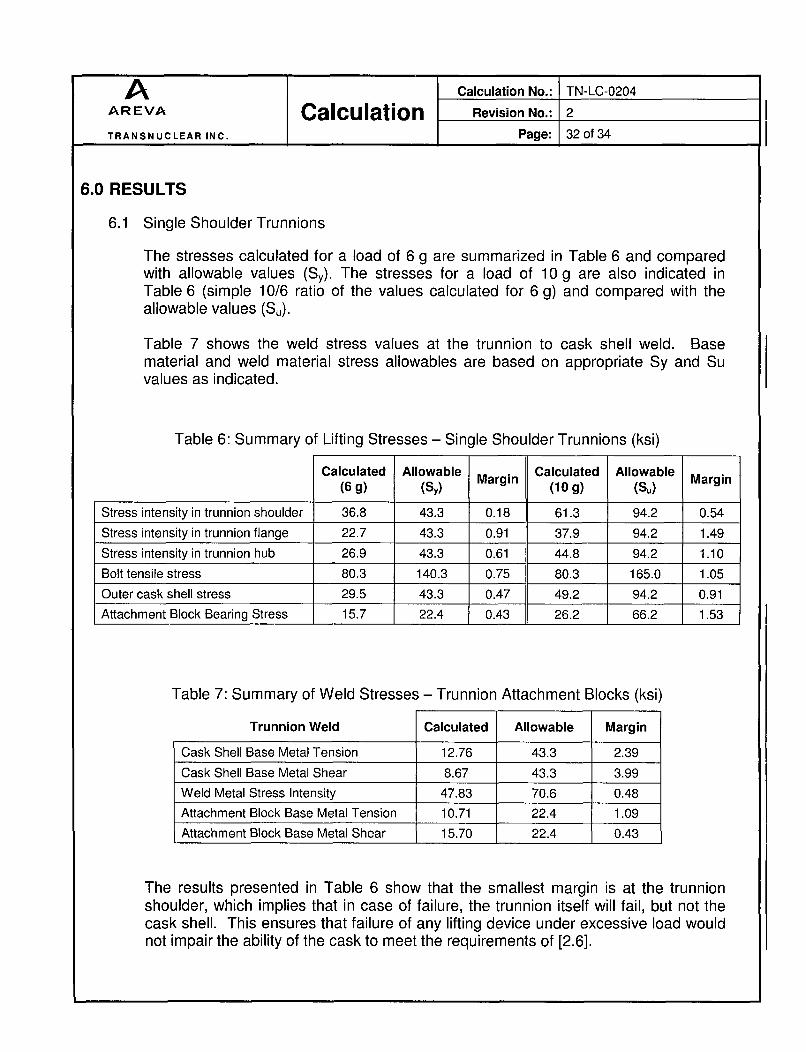
6.0 RESULTS
6.1 Single Shoulder Trunnions
The stresses calculated for a load of 6 g are summarized in Table 6 and comparedwith allowable values (Sy). The stresses for a load of 10 g are also indicated inTable 6 (simple 10/6 ratio of the values calculated for 6 g) and compared with theallowable values (Se).
Table 7 shows the weld stress values at the trunnion to cask shell weld. Basematerial and weld material stress allowables are based on appropriate Sy and Suvalues as indicated.
Table 6: Summary of Lifting Stresses - Single Shoulder Trunnions (ksi)
Calculated(6 g)
Allowable(SY) Margin Calculated
(10 g)Allowable
(SU) Margin
Stress intensity in trunnion shoulder 36.8 43.3 0.18 61.3 94.2 0.54
Stress intensity in trunnion flange 22.7 43.3 0.91 37.9 94.2 1.49
Stress intensity in trunnion hub 26.9 43.3 0.61 44.8 94.2 1.10
Bolt tensile stress 80.3 140.3 0.75 80.3 165.0 1.05
Outer cask shell stress 29.5 43.3 0.47 49.2 94.2 0.91
Attachment Block Bearing Stress 15.7 22.4 0.43 26.2 66.2 1.53
Table 7: Summary of Weld Stresses - Trunnion Attachment Blocks (ksi)
Trunnion Weld Calculated Allowable Margin
Cask Shell Base Metal Tension 12.76 43.3 2.39
Cask Shell Base Metal Shear 8.67 43.3 3.99
Weld Metal Stress Intensity 47.83 70.6 0.48
Attachment Block Base Metal Tension 10.71 22.4 1.09
Attachment Block Base Metal Shear 15.70 22.4 0.43
The results presented in Table 6 show that the smallest margin is at the trunnionshoulder, which implies that in case of failure, the trunnion itself will fail, but not thecask shell. This ensures that failure of any lifting device under excessive load wouldnot impair the ability of the cask to meet the requirements of [2.6].

A Calculation No.: TN-LC-0204AREVA Calculation Revision No.: 2
TRANSNUCLEAR INC. Page: 33of34
The minimum required engagement length is 1.406 in. According to [2.4], helicoils1185-16CN-3000 are used. The maximum threaded length of the bolt is equal to1.63 in, which is greater than the minimum required engagement length.
6.2 Shear Key Bearing Block
The stresses calculated for a longitudinal load of 10 g are summarized in Table 8 andcompared with allowable values.
Table 8: Summary of Longitudinal Stresses - Shear Key Bearing Block (ksi)
Calculated(10 g)
Allowable(SY or 0.6xSy)
Margin
Bearing stress 20.1 84.6 3.20
Bending stress 3.4 84.6 24.08
Shear key bearing block Shear stress 6.2 50.8 7.25
Maximum stress intensity 12.8 84.6 5.63
Bending stress in the weld with 16.1 22.4 0.39pad plate
Weld between pad plate Shear stress in base metal 7.2 13.4 0.86and cask outer shell I I

A Calculation No.: TN-LC-0204AREVA Calculation Revision No.: 2
TRANSNUCLEAR INC. Page: 34 of 34
7.0 CONCLUSIONS
All of the stresses calculated above are less than the allowable stresses.
7.1 Trunnion Assembly
Based on the above calculations, the trunnion design meets the requirements of10CFR71.45 and ANSI N14.6.
7.2 Shear Key Assembly
Based on the above calculations, the design meets the requirements of 1 OCFR71.
8.0 LISTING OF COMPUTER FILES
Below is listing of computer file used for computing the trunnion and shear key assemblystresses.
File Name Time Description
TN- LC-0204-Rev2. As 09/16/2013 TN-LC transport cask trunnion, trunnion local stress and2:49 PM tie-down system stress evaluation.