end of addendum 2 - ci.carlton.or.us · addendum no. 2 city of carlton mw&l-carlton emergency...
TRANSCRIPT

ADDENDUM NO. 2 CITY OF CARLTON MW&L-CARLTON EMERGENCY INTERTIE PROJECT
CITY OF CARLTON
MW&L-CARLTON EMERGENCY INTERTIE PROJECT
ADDENDUM NO. 2
Bid Opening: March 1st, 2018 at 2:00pm at Carlton City Hall
This Addendum modifies the original bidding documents and is included in the Contract Documents. Receipt of this Addendum is to be acknowledged in the space provided in the Bid Form. Failure to acknowledge this Addendum may result in the bid being considered nonresponsive. Item Specification or Sheet Change
2.01 Division 17 specifications
Replace the existing 17 specifications with the section in this addendum. The changes are for the Schedule B SCADA upgrade.
End of Addendum 2

135-13914-16001-02
Instrumentation and Control Systems 17000-1 01/2018
SECTION 17000 INSTRUMENTATION AND CONTROL SYSTEMS
1. GENERAL
1.01 DESCRIPTION OF WORK
A. Scope:
1. General: This section specifies general requirements applicable to process instrumentation systems consisting of process sensors, monitoring and control devices, and accessories required to provide a complete and fully functional monitoring and control system.
2. Responsibility: The Contractor shall provide, configure, calibrate, program, test, and commission all components of the instrumentation, control, communications, and network systems supplied (UNO). The Contractor shall place the completed systems in operation, including tuning loops and making final adjustments to instruments as required during plant start-up. The Contractor shall provide the services of instrument technicians for testing and adjustment activities.
3. Related Requirements: Division 40 is an extension of, and includes all of the requirements of Division 26, Electrical. All work performed under Division 40 shall also comply with the applicable sections of Division 26 as well as the general provisions of Divisions 0 & 1.
B. Contract Requirements:
1. General Conditions, Supplementary Conditions, and Division 1 apply to Work in this section.
C. Definitions:
1. General: The definitions of terminology used in these specifications shall be defined in ISA Standard S51.1, unless otherwise specified.
2. Approved Equal: Items that are accepted and approved by the Owner, the Owner’s designated Project Representative, or the Engineer as being functionally equivalent for the application and acceptably substitutes for items specified in the Contract Documents.
3. BOM: Bill of Materials
4. Contractor: The General Contractor is responsible for overall project construction. The party with whom the contract is executed.
5. COS: Commercial off the Shelf
135-13914-16001-02
Instrumentation and Control Systems 17000-2 01/2018
6. CSI: Control System Integrator. An organization engaged in the business of detail design, component purchase, assembly, programming, and implementing process control and industrial electronic systems.
7. Data Sheets: Data sheets as used in this specification shall refer to ISA S20.
8. Galvanic Isolation: Pertaining to an electrical node having no direct current path to another electrical node. As used in this specification, galvanic isolation refers to a device with electrical inputs and/or outputs which are galvanically isolated from ground, the device case, the process fluid, and any separate power supply terminals, but such inputs and/or outputs are capable of being externally grounded without affecting the characteristics of the devices or providing path for circulation of ground currents.
9. GC: General Contractor
10. HMI: Human Machine Interface.
11. Integrated Circuit: A number of circuit elements inseparably associated on or within a continuous body to perform the function of a circuit.
12. NA: Not Applicable
13. Panel: An instrument support system which may be either a flat surface, a partial enclosure, or a complete enclosure for instruments and other devices used in process control systems. Panels may provide mechanical protection, electrical isolation, and protection from dust, dirt, and chemical contaminants which may be present in the atmosphere. "Panel" shall be understood to include consoles, cabinets, and racks.
14. PDF: Portable Document Format
15. OIT: Touch screen Operator Interface Terminal. Used for HMI as specified.
16. SCADA: Supervisory Control and Data Acquisition.
17. Signal Types: The following types of signals are used in systems specified in this division.
a. Low Level Analog: A signal that has a full output level of 100 millivolts or less. This group includes thermocouples and resistance temperature detectors.
b. Digital Code: Coded information such as that derived from the output of an analog to digital converter or the coded output from a digital computer or other digital transmission terminal. This type includes those cases where direct line driving is utilized and not those cases where the signal is modulated.
135-13914-16001-02
Instrumentation and Control Systems 17000-3 01/2018
c. Pulse Frequency: Counting pulses such as those emitted from speed transmitters.
d. High Level Analog: Signals with full output level greater than 100 millivolts but less than 30 volts, including 4-20 mA transmission.
e. Modulated Signals: Signals emanating from modems or low level audio signals. Normal signal level is plus 4 dBm to minus 22 dBm. Frequency range is 300 to 10,000 hertz.
f. Discrete Events: Dry contact closures monitored by solid-state equipment. If the conductors connecting to dry contacts enter enclosures containing power or control circuits and cannot be isolated from such circuits in accordance with NEC Article 725, this signal shall be treated as low voltage control.
g. Low Voltage Control: Contact closures monitored by relays, or control circuits operating at less than 30 volts and 250 milliamperes.
h. High Level Audio Signals: Audio signals exceeding plus 4 dBm, including loud speaker circuits.
i. Radio Frequency Signals: Continuous wave, alternating current signals with fundamental frequency greater than 10 kilohertz.
j. 120 VAC control: Contact closures monitored by relays, or control circuits operating at 120 volts AC.
18. Solid State: Circuitry or components of a type which convey electrons by means of solid material such as silicon or crystals, or which work on magnetic principles such as ferrite cores. Vacuum tubes, gas tubes, slide wires, stepping motors, or other devices are not acceptable substitutes for solid-state components or circuitry.
19. Two-Wire Transmitter: A transducer which derives operating power supply from the signal transmission circuit and therefore requires no separate power supply connections. As used in this specification, two-wire transmitter refers to a transmitter which produces a 4 to 20-milliampere, current-regulated signal in a series circuit with a 24-volt direct current driving potential and a maximum circuit resistance of 600 ohms.
20. UNO: Unless specifically Noted Otherwise. All general requirements statements shall apply as stated except where specific exceptions are stated, in which case the general requirement shall be modified by the stated exception.
1.02 QUALITY ASSURANCE
A. Referenced Standards: The latest edition of the documents and applicable standards and recommended practices listed below are included in the Contract by reference.
135-13914-16001-02
Instrumentation and Control Systems 17000-4 01/2018
1. American National Standards Institute (ANSI)
2. Institute of Electrical and Electronic Engineers (IEEE)
3. Underwriters' Laboratories (UL)
4. The Instrumentation, Systems, and Automation Society (ISA)
5. PLCopen Foundation
6. IEC 61131-3
7. API RP550: Manual on Installation of Refinery Instruments and Control Systems, Part I – Process Instrumentation and Control Sections 1 Through 13
8. API RP 551: Process Measurement Instrumentation
9. API RP 552: Transmission Systems - first Edition
10. ANSI/ISA S5.4: Instrument Loop Diagrams
11. ISA S20: Specification Forms for Process Measurement and Control Instrumentation, Primary Elements, and Control Valves
12. ANSI/ISA S5.1: Instrumentation symbols and Identification
13. ANSI/ISA S51.1: Process Instrumentation Terminology
14. ISA S5.3: Graphic Symbols for Distributed Control/Shared Display Instrumentation, Logic, and Computer systems
15. ISA RP12.2.02: Recommendations for the Preparation, Content, and Organization of Intrinsic Safety Control Drawings
16. NFPA 70 National Electric Code (NEC)
17. NFPA 79 Electrical Standards for Industrial Machinery
18. NFPA 820 Fire Protection in Wastewater Treatment and Collection Facilities
19. IBC 1632 International Building Code
20. UL 508 Industrial Control Equipment
B. Listing:
1. All materials and equipment specified herein shall be within the scope of Nationally Recognized Testing Laboratory (NRTL) examination services, be approved by the NRTL for the purpose for which they are used, and shall bear the appropriate listing/label.

135-13914-16001-02
Instrumentation and Control Systems 17000-5 01/2018
2. Equipment shall be listed/labeled by an NRTL acceptable to the local authority having jurisdiction.
3. When a product is not available with a listing/label for the purpose for which it is to serve, the product may be required by the inspection authority to undergo a special inspection at the manufacturer’s place of assembly or as a completed assembly in the field. All costs and expenses incurred for such inspections shall be included in the original contract price.
1.03 SUBMITTALS
A. General: Submit information in compliance with procedures established in WSDOT Standard Specifications for Road, Bridge and Municipal Construction; Part 1.06 Control of Materials.
B. Media:
1. Initial Submittals shall be provided in electronic .PDF format, and shall be electronically transmitted via e-mail or made available for downloading by e-mailing a functional link to the Contractor’s FTP or similar share-point site.
2. Conformed Shop Drawings shall be delivered to the Engineer in bound hard-copy form, using standard tabloid 11” x 17” page size. Include hard card-stock front and back cover. Include project and Contractor information on the front cover. Provide electronic source files on USB flash drive media, or on a USB solid-state backup hard drive. Select appropriate media based on storage capacity required for files.
C. Organization and Format:
1. The following Submittals shall be organized under separate covers.
a. Qualifications
b. Product Data Sheets – provide all required product datasheets within a single comprehensive submittal.
c. Shop Drawings– provide all required shop drawings within a single comprehensive submittal.
1) SIZE: Hardcopy plots shall be 11-inch by 17-inch (half-size).
2) TEXT: Minimum Text size: 0.125 inch for 22 x 34 inch drawings, 0.063 inch for 11 x 17 inch drawings.
3) BOARDERS: Drawings shall have borders and title blocks identifying the Contract, facility, system, revisions to the drawing, and type of drawing.
135-13914-16001-02
Instrumentation and Control Systems 17000-6 01/2018
4) REVISIONS: Each release of a drawing shall carry a revision number, date, and a brief description of the changes. All changes associated with a given release shall be indicated on the drawing by a revision flag. Changes on the latest revision shall be indicated by clouding.
5) CAD: Drafting software shall be AutoCAD 2008 or latter. Bind all x-refs.
d. Completed Testing and calibration Forms – provide all completed testing and calibration forms within a single comprehensive submittal.
e. As-constructed Field Markups (Contractor redlines)
f. Operations and Maintenance Manuals
2. Segregate submittal materials in a manner which groups materials consistently with Specifications sections divisional organization.
3. Include a comprehensive Index identifying each product submitted, and pages where applicable information can be found. Locate immediately after any inside covers and transmittals. PDF documents shall include bookmark links to each product identified within the Index. Organize bookmarks in a hierarchical tree structure.
4. For product datasheets; at the beginning of each divisional section, include specified product requirements (Part 2 – Products) from the Specifications, and therein notate Contractor compliance, or non-compliance with each specified requirement. Non-complying items may be accepted or rejected by the Engineer based on best judgement and circumstances. Include detailed explanation for all non-complying items noted.
5. Shop Drawings shall include a comprehensive Bill of Materials (BOM) which shall be indexed and cross-referenced using a unique identifier to:
a. Products within the submitted product data sheets
b. Individual components shown within shop drawings including schematics, panel layouts, and schedules.
6. Improperly organized or notated submittals may be returned to the Contractor without review for their subsequent correction and re-submittal as required.
D. Reviews and Submittals
1. Review of submittal materials by the Project Representative is provided as a courtesy for the convenience of the Contractor, and does not in any respect relieve the Contractor from full compliance with the Contract.

135-13914-16001-02
Instrumentation and Control Systems 17000-7 01/2018
2. The Project Representative will review the Contractor’s Submittal materials and issue one of the following assessment status for each item:
a. No Exceptions Taken
b. Exceptions noted
c. Submit for review
d. Revise and Resubmit
e. Rejected
3. Items with status of Exceptions Noted, Submit for Review, Revise and Resubmit, and Rejected shall be corrected and re-submitted by the Contractor. Resubmittals shall:
a. Include Contractor responses to each submittal review comments separately and at a level of detail commensurate with each comment.
b. Supplier responses, where applicable, shall indicate how the Supplier resolved the issue pertaining to each review comment. The Contractor is fully responsible for ensuring that their Suppliers present and offer materials and equipment which comply in every detail to the requirements of the Contract.
c. Fully describe the actions which have been taken to resolve the non-compliant aspect of the comments. Contractor responses that only indicate that the review comment was noted, will be looked into, etc., are not satisfactory.
d. Re-submittals which do not comply with this requirement may be rejected and returned without review.
e. Contract time extensions will not be allowed due to impacts related to the rejection and subsequent re-review of non-compliant submittals.
f. Submittal review comments not addressed by the contractor in re submittals shall remain in full force and shall continue to apply, whether restated or not in subsequent reviews, until adequately addressed by the contractor to the satisfaction of the Project Representative.
E. Detailed Requirements
1. Qualifications: Submit information about the Contractor’s proposed CSI including employee resumes, company information, etc., as required by any Division 40 specification sections.
2. Product Data: Submit product datasheets for each product required for this project.
135-13914-16001-02
Instrumentation and Control Systems 17000-8 01/2018
a. Include Manufacture name and part number for each product
b. Cross out or otherwise obliterate all extraneous materials and information not applicable to this project.
c. Clearly identify all configuration options for the equipment to be furnished.
d. Part ordering numbers shall include a comprehensive ordering key; which clearly describes all Manufacturer available options, and the selected options for this project.
e. Include product dimensions and requirements for mounting and securing.
f. Include diagrams for terminal identification and layouts
g. Identify electrical capacities and characteristics
h. Include operational description where applicable
i. Indicate UL or other independent testing lab certifications which apply
j. Indicate range of environmental conditions applicable to reliable service. Including IP rating, resistance to chemicals, applicability to classified areas, temperature limits, humidity limits, etc.
k. Certifications:
1) Temperature: Provide test data certified by the manufacturer to demonstrate that field electronic devices are suitable for the specified ambient temperatures.
2) Corrosion: Provide test data showing design features of the electronic equipment provided to protect against damage by the specified atmospheric contaminants and specific evidence that similarly protected electronic equipment has operated in similar environments for a period of not less than five years without failure due to corrosion.
3. Shop Drawings
a. Drawings: Submit all drawings described in this and other Division 40 sections including
1) Site-specific layout plans, elevations and details describing field installation requirements
2) Elementary, loop, schematic, wiring details.
a) Submit detailed interconnection diagrams, wiring diagrams, elementary diagrams, communications diagrams, and loop
135-13914-16001-02
Instrumentation and Control Systems 17000-9 01/2018
diagrams with all electrical and electronic components clearly identified by project tag number consistent with the contract drawings and schedules.
b) Diagrams for each circuit or element shall be separate and unique. Typical diagrams are not allowed.
c) Wiring and loop diagrams shall carry a uniform and coordinated set of wire numbers and terminal block numbers in compliance with Division 26 and Section 409513.
d) Field Equipment Terminals: All schematics, diagrams, and drawings showing connections to field equipment shall provide correct terminal block numbers for the connections at the field equipment. This includes packaged system control panels, MCCs, stand-alone motor controls, valve actuators, instruments, switches, etc. The contractor, subcontractors, and suppliers shall coordinate as needed to accomplish this.
e) Comply with NFPA79 – Electrical Standard for Industrial Machinery.
f) Show components of a control panel in an arrangement similar to the actual layout of the panel.
g) Show internal wiring between devices within the panel.
h) Show all terminal blocks whether used for internal or field wiring. Those used for field wiring shall be clearly identified as such.
i) Wiring diagrams shall indicate insulation color code, signal polarities, wire numbers, and terminal block numbers.
j) Submit complete interconnection diagrams for field wiring.
k) Show each panel and field devices.
l) Show wire numbers, cable numbers, panel numbers, and field device tag numbers.
3) Fabrication, Panel Layout and Assembly Drawings
a) Submit detailed construction drawings for panel layouts and equipment enclosures with dimensions in inches. Show both exterior and interior views.
b) Provide arrangement drawings of all panel front and internal-mounted instruments, switches, devices, and

135-13914-16001-02
Instrumentation and Control Systems 17000-10 01/2018
equipment indicated. All panel mounting details shall be shown. Outer dimensions of all panels shall be included on the drawing. Deviations from approved arrangements shall require Project Representatives approval prior to installation. Arrangement drawings shall be drawn to scale using standard Architectural or Engineering scales.
4) Update drawings following submittal review, factory test, and commissioning. Updates shall be provided to the Project Representative in a timely manner. Utilize revision clouds to identify specific changes to the work.
5) Cross reference drawing elements with BOM and product datasheets using unique references.
6) Drawings shall use project-specific tag formats and numbers.
7) Unique and separate drawings shall be provided for each item supplied including but not limited to all panels and all MCC units.
8) Typical drawings that apply to multiple panels or multiple MCC motor control units are not acceptable.
9) Drawings shall be prepared utilizing a computer aided drafting program. CAD shop drawings shall be updated and provided to the Project Representative prior to factory testing, prior to system installation, and with the O&M manuals.
10) Version Control: Diagrams shall carry a date and brief description of the revisions.
11) Symbols: Drawing symbol format shall comply with NFPA 79, ISA 5.1, ISA 5.3 and where appropriate, ISA RP 12.2.02.
12) Seismic: Submit Seismic design and anchoring information for applicable equipment weighing 200 pounds or more.
4. Bill of Materials: Include all items, products, and assemblies supplied.
a. Documents shall be updated following submittal review, factory test, and commissioning. Updates shall be provided to the Project Representative in a timely manner. Bill of materials shall include the following information:
1) Provide in spreadsheet format, inserted into Shop Drawing sheets.
2) Page layout to be landscape orientation with sheet width suitable for printing on standard 11 x 17 tabloid paper when printed at 50% reduced size. Reduced size printing shall result in text font height of no less than 0.0625-inch minimum (0.125-inch full-size.)

135-13914-16001-02
Instrumentation and Control Systems 17000-11 01/2018
3) Include repeated column headings for each page of material.
4) Include spreadsheet title “Bill of Materials”.
5) Include issuance / revision date.
6) Arrange columns as follows:
a) Column A – item / index number
b) Column B – applicable specification section
c) Column C – Material description
d) Column D – Material quantity
e) Column E – Unit of measure
f) Column F – Manufacturer Name
g) Column G – Manufacturer Model Number
h) Column H – Selected Options / accessories
i) Column I - Footnotes
j) Item number, index, or key shall be cross-referenced and applied consistently to submitted product datasheets, drawings, schedules, etc.
k) Item manufacturer's name, model, and part numbers. Supplier unique part numbers are not acceptable.
l) Description
m) Quantity supplied
n) Supplier contact information
7) Contractor shall note all spare units provided within the BOM.
b. Packaged Equipment: All packaged equipment suppliers shall provide submittals in compliance with Division 40. This shall include packaged equipment purchased under the contract as well as any pre purchased packaged equipment assigned to the contractor.
5. As-Constructed Markups: The Contractor shall keep record of all required as-constructed deviations from those shown in the Bid Documents and approved shop drawings.
a. Maintain a red-line set of as-constructed conditions on site at all times.
135-13914-16001-02
Instrumentation and Control Systems 17000-12 01/2018
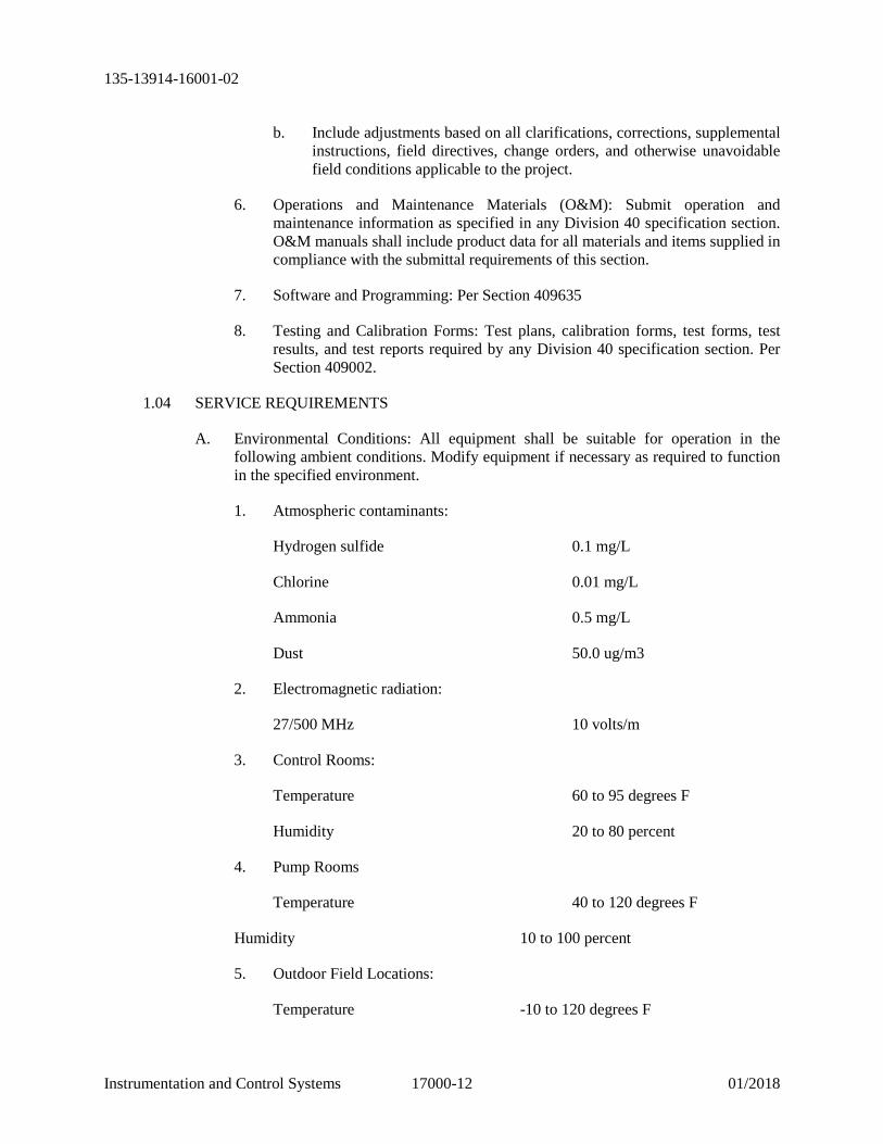
b. Include adjustments based on all clarifications, corrections, supplemental instructions, field directives, change orders, and otherwise unavoidable field conditions applicable to the project.
6. Operations and Maintenance Materials (O&M): Submit operation and maintenance information as specified in any Division 40 specification section. O&M manuals shall include product data for all materials and items supplied in compliance with the submittal requirements of this section.
7. Software and Programming: Per Section 409635
8. Testing and Calibration Forms: Test plans, calibration forms, test forms, test results, and test reports required by any Division 40 specification section. Per Section 409002.
1.04 SERVICE REQUIREMENTS
A. Environmental Conditions: All equipment shall be suitable for operation in the following ambient conditions. Modify equipment if necessary as required to function in the specified environment.
1. Atmospheric contaminants:
Hydrogen sulfide 0.1 mg/L
Chlorine 0.01 mg/L
Ammonia 0.5 mg/L
Dust 50.0 ug/m3
2. Electromagnetic radiation:
27/500 MHz 10 volts/m
3. Control Rooms:
Temperature 60 to 95 degrees F
Humidity 20 to 80 percent
4. Pump Rooms
Temperature 40 to 120 degrees F
Humidity 10 to 100 percent
5. Outdoor Field Locations:
Temperature -10 to 120 degrees F
135-13914-16001-02
Instrumentation and Control Systems 17000-13 01/2018
Humidity 10 to 100 percent
1.05 DESCRIPTION OF SYSTEM
A. General:
1. System Scope: The instrumentation and control system shall include the instruments, control devices, programmable controllers, input and output devices, sensors, interfacing devices, communications devices, cabinets, enclosures, and other components, as required to implement the functional requirements of the Contract.
2. Design and Assembly: The instrumentation and control system shall be designed and assembled by the CSI to be an integrated system composed completely of components that are specifically designed and intended to be used for and in conjunction with the control and operation of a valve system. The control system shall be designed and assembled by the CSI to provide:
a. Control of a valve system as shown on the drawings
b. New SCADA HMI shall be like controls of existing system
c. Reliable communications with the New SCADA system.
3. Custom Parts: System components shall be commercial, off-the-shelf (COS) components. Custom designed or manufactured components shall require Project Representatives approval.
B. Functional Requirements:
1. Bid Documents: As defined in Division 40 specifications and the contract drawings.
2. Manual Functions: NA
3. Fault Tolerance: NA
4. Location of Functions: Existing system functions will stay the same, SCADA HMI shall be new Graphics with the same functionality as the existing system with the addition of the new valve system.
1.06 CONTROL SYSTEM INTEGRATOR (CSI) ROLES AND RESPONSIBILITIES
A. Systems Responsibility:
1. All instrumentation and industrial electronic systems and functions shall be provided under the supervision of a single Control System Integrator, chosen by the Contractor, who is regularly engaged in the design, programming, configuration, and installation of similar systems of equal or greater scope and complexity.

135-13914-16001-02
Instrumentation and Control Systems 17000-14 01/2018
2. The Control System Integrator shall be enjoined to the Contract as a Subcontractor.
3. The assignment of specific responsibilities herein to the Control System Integrator shall not, in any way or under any conditions, diminish the Contractor's full and complete responsibility for all work performed and all materials installed under the contract.
4. The Contractor shall ensure that the Control System Integrator conforms to and meets all requirements specified in the contract documents. The assignment of the Control System Integrator as an equipment supplier shall not be acceptable.
5. Intent of the drawings and specifications:
a. General: Except where specifically noted as “no equal” or “no substitutions”, the contract documents do not dictate the use of specific brands or models of components and equipment.
1) The control system drawings are intended to primarily convey detailed functional and operational requirements of the control system rather than specific component selection, assembly, and interconnection information.
2) The substantial interconnection information provided in the Contract Drawings is general in nature and is provided for the purpose of indicating the general scope of work and the aforementioned functional and operational requirements, and shall not be construed to represent detailed shop drawings or parts thereof.
b. Ancillary Components Required: Components not explicitly indicated in the Contract Documents but none-the-less implied, required for the environment or area classification indicated, or required for the proper functioning of the system shall be considered required just as though they had been explicitly indicated. The ancillary components shall be considered incidental to the Contract, and shall not constitute a basis for claims by the Contractor for additional time or compensation to complete the Work.
B. Control System Integrator’s Responsibility:
1. Sole Responsibility: The Control System Integrator (CSI) shall be solely and completely responsible for the detailed design, assembly, programming, and commissioning of the entire control system unless otherwise noted.
2. Design and Performance: The control system hardware and assemblies shall be designed by the CSI to provide the control capabilities and functions indicated in and implied by the drawings and these specifications and to provide trouble-free operation with a minimum of maintenance.

135-13914-16001-02
Instrumentation and Control Systems 17000-15 01/2018
3. CSI Coordination and Integration
a. Coordinate and integrate the control system with motor controls, packaged equipment controls, and other related equipment.
b. Obtain submittal information on equipment specified, provided by other suppliers, or other disciplines and integrate all the equipment into a comprehensive control system to form a complete working system as outlined by the Contract Documents.
c. Communicate directly with the manufacturer(s) and supplier(s) of all related equipment to determine all details of the equipment that may influence or affect the control system.
d. Determine all requirements for and shall cause integration of the control system into a unified operating system.
e. Include Carbon Copying (cc:) the General Contractor for all correspondence related to coordination
4. CSI Additional Itemized Responsibilities:
a. Field investigate existing conditions, including retrieval of existing PLC, and HMI programs needed for offline conversion and testing.
b. Develop Detailed Design of Control Panels: NA
c. Develop Detailed Design of Control Circuitry:
1) Select all control system components, except for items indicated as “no equal”, or “no substitutions” within the specifications.
2) Develop detailed circuit design and component interconnection required to meet the general and functional requirements indicated in or implied by the Drawings and Specifications.
3) Select and design miscellaneous or interfacing components and wiring required to integrate components specified as “no equal” or “no substitutions”.
4) Select components which are suitable for environmental and other conditions of application.
5) Define all requirements for all interfacing components
6) Provide all appurtenances, accessories, and all such devices which may be required for safe and proper functioning and interfacing of components as part of the control system. Examples of such appurtenances include, but are not limited to:
135-13914-16001-02
Instrumentation and Control Systems 17000-16 01/2018
a) Interposing relays
b) Analog isolators
c) Fuses
d) Terminals
e) Media converters
f) Intrinsic barriers
g) Power supplies
7) Design all interconnecting wiring of the valve system
5. CSI Equipment Testing: NA
6. CSI Integration Testing: NA
7. CSI Coordination with GC
a. Coordinate with the Contractor for specific requirements and locations of raceway penetrations and field wiring in control panels.
b. Provide the Contractor with all necessary detailed installation drawings and/or written instruction for installation of all control components and sensing devices as required for proper system operation.
8. CSI Calibration: NA
9. CSI Communications and Networks
a. Set up, configuration, test, and verification of all communications equipment, channels, and networks including new and reused telephone circuits.
10. CSI Startup and Testing
a. Provide services for system start up, commissioning, functional testing following installation specifications.
11. CSI Procurement Responsibility: Unless specifically noted otherwise;
a. Provide computer data processing equipment including workstation, monitor, UPS equipment as applicable.
b. Provide all software and associated licenses
12. CSI Configuration and Programming
135-13914-16001-02
Instrumentation and Control Systems 17000-17 01/2018
a. Configure and program all supplied devices, equipment, and software unless specifically noted otherwise. Configuration and programming of devices and equipment supplied as a part of packaged systems shall be provided by the vendor of each packaged system.
13. CSI Application Software Development:
a. Install and program all software systems provided under software system
14. CSI Equipment Submittal Review
a. Review all valve system controls
b. Notify the Contractor of any and all needed modifications to submitted equipment, package system scope of services or supply, or CSI supplied equipment required to accommodate and integrate submitted equipment into the CSI's work.
15. Training
a. Provide services for on-site training to Owner’s Personnel of New SCADA System and Valve System. Minimum 4 Hrs
C. CSI Submittal Materials
1. Product Data Sheets: collect, mark up, assemble, and organize product datasheets applicable to this Project.
2. SHOP DRAWINGS: Engineer, prepare, assemble, and organize all shop drawings for submission by the Contractor.
3. Record Drawings: All submitted drawings shall be updated over the course of the construction project to reflect the installations and equipment as-built. A full set of record drawings shall be provided to the Project Representative upon completion of the project and shall be included in the O&M manuals. Record drawing requirements shall be the same as submittal drawing requirements.
4. As-Constructed Field Markup Drawings: Maintain on site a set of record plan and P&ID markup drawings on site during construction. The contractor shall mark up the record drawing set to indicate any and all deviations of the installed systems from the contract documents. The marked-up drawings shall be provided to the project representative at project close out.
1.07 CSI QUALIFICATIONS
A. The Control System shall be designed, constructed, and commissioned by full time or contract employees with a minimum of 5 years of experience and a minimum of one year with Integrator.
135-13914-16001-02
Instrumentation and Control Systems 17000-18 01/2018
B. The CSI shall configure and program all devices and equipment supplied to perform the functions indicated in the contract documents unless specifically noted otherwise. Engineering and programming services shall only be provided by staff members directly employed by the CSI. Contract labor is not acceptable for engineering and programming services.
C. Prequalified Integrators: CSI’s acceptable for this project include the following companies.
1. The Automation Group – Eugene, OR
D. Evaluation of Integrators and Personnel
1. Withholding of Approval: The Contractor and the proposed CSI shall anticipate that the Project Representative may withhold approval of a proposed CSI or employee if, in the opinion of the Project Representative, the CSI or employee does not have the experience, capability, or an acceptable performance and execution record of similar projects in the past. No Contractor, CSI, or employee denied approval by the Project Representative shall be entitled to any extension of time or to any claim for damages related to any consequences resulting from the withholding of approval for any reason whatsoever. Applicable consequences may include but are not limited to associated extra or unanticipated costs, hindrances, delays, or complications of any kind.
E. Requirements for Alternates: The acceptability of a proposed alternate CSI will be determined solely by the Project Representative. The CSI shall be an instrument and control system manufacturing company that conforms to the following requirements:
1. Location: The CSI’s manufacturing and assembly facility shall be located within a 100 mile drive from the Owner’s offices and the job site.
2. Specialty: The CSI shall be specialized in the design, assembly, testing, installation, programming, commissioning, and service of municipal control and communication systems in the Pacific Northwest for at least five years.
3. Employee Experience: The CSI shall employ technicians and engineers with documented experience in the design, assembly, testing, installation, operation, calibration, trouble-shooting, service, and repair of control and communication systems for municipal waterworks and sewerage facilities.
4. Similar Experience: The CSI shall have completed the design, assembly, testing, installation, and commissioning of control systems which include the instruments, components, equipment, and devices cited on the Plans by specific manufacturer's name.
5. Spare Parts Stocks: NA
135-13914-16001-02
Instrumentation and Control Systems 17000-19 01/2018
6. Alternate Supplier Information: Prior to placement of purchase orders for services and equipment, the Contractor shall provide the following information about a proposed alternate CSI:
a. Company Information: Description of Ownership and organization of Integrator.
b. Resumes: Resumes of principals and/or key employees who will be working directly in the engineering, design, assembly, testing, and commissioning of the system for this project.
c. Expertise: Description of expertise in design, assembly, testing, and installation of control systems for municipal waterworks and sewerage facilities.
d. Project Resume: Description of municipal control systems designed, assembled, and installed in the last five (5) years. Description shall include:
1) Names of employees involved in each system.
2) Detailed description and drawings of each system.
3) Cost of each system.
4) Names and telephone numbers of persons involved in operation and maintenance of each system.
e. Service: Description of the service capabilities normally provided by the company including resumes of employees assigned to field service and listing of service equipment.
f. Spare Parts: Description of spare parts normally stocked and of restocking procedures.
g. Additional Information: Additional information that may assist the Project Representative in ascertaining the company's general ability to perform the work.
h. Warranty: Written agreement to the warrantee service terms of the contract documents.
135-13914-16001-02
Instrumentation and Control Systems 17000-20 01/2018
2. PRODUCTS
2.01 ACCEPTABLE MANUFACTURERS
A. Products: All products provided by the CSI shall be manufactured to comply with the listing requirements identified in Part 1 and other requirements as indicated in the Contract. System components shall be commercial, off-the-shelf components to the maximum extent possible. Custom designed or manufactured components shall require Project Representative’s approval.
2.02 MATERIALS
A. General: Material shall be new, free from defects, and of the quality specified. All equipment and materials utilized in the system shall be the products of Manufacturers with at least five (5) years of experience in the manufacture of similar equipment. Similar items in the system shall be the products of the same Manufacturer. All equipment shall be of industrial grade and of standard construction, shall be capable of long, reliable, trouble-free service, and shall be specifically intended for control and monitoring of operation of motor-driven pumps and process equipment. All equipment shall be of modular design to facilitate interchangeability of parts and to assure ease of servicing.
B. Electronic Components: Unless otherwise specified, electronic equipment shall be of solid-state construction. Components of standard electronic assemblies shall not be replaced with components of different characteristics in order to meet the performance requirements of the specification. Parts shall be as shown in the instruction manuals and shall be replaceable with standard commercial components of the same description without degrading the performance of the completed assembly.
2.03 INSTRUMENTS: NA
2.04 SPARE PARTS: NA
3. EXECUTION
3.01 DESIGN AND ASSEMBLY
A. General: The supplied control systems shall be designed by the CSI. The supplied control system shall be completely assembled in the shop of and by the CSI. All components and equipment shall be prewired to the maximum extent possible.
B. Integration: The CSI shall determine all requirements for the valve system
C. Review of Submittals: The CSI shall be directly responsible to obtain submittal information on related equipment supplied by others and to integrate this information as required with the overall control system to form a complete working package.
D. Coordination: The CSI shall communicate directly with the Manufacturer(s) and Supplier(s) of all related equipment to determine all details of the equipment that may
135-13914-16001-02
Instrumentation and Control Systems 17000-21 01/2018
influence or affect the supplied control system components. The CSI shall make any and all adjustments or revisions required to integrate the submitted equipment into the job at no additional expense to the Owner and with no extension of the schedule.
3.02 DELIVERY, STORAGE, AND HANDLING
A. Shipping:
1. Anchor, brace, and protect equipment during shipping handling.
B. Delivery Inspection: Notify the Project Representative and provide access for inspection upon arrival of any material or equipment to be incorporated into the work. Remove protective covers when required.
C. Supplied Control Panels: NA
3.03 INSTALLATION
A. General
1. Delivery: Contractor shall be fully responsible for delivery of materials from the CSI and supplier’s place of business to the project jobsite location(s).
2. Installation by Contractor: The valve system shall be install by the Conntractor
3. Installation Instructions: The control system shall be installed in accordance with the installation drawings and instructions provided by the CSI, packaged system suppliers, and other equipment suppliers.
4. Supervision: The CSI's instrumentation and controls project engineer shall supervise and coordinate all activities related to the installation of Division 40 requirements.
5. Expertise of Installer: Installation shall be performed by workers who are skilled and experienced in the installation of electrical instrumentation and control systems. Installation shall include all elements and components of the control systems and all conduit and interconnecting wiring between all elements, components, sensors, valve operators, etc.
6. Locations: Equipment shall be located so that it is readily accessible for operation and maintenance.
7. Instrument Technician: NA
B. Signal Connection and Transmission
1. Unless otherwise specified, analog signal transmission between electric or electronic instruments not located within a common panel shall be 4 to 20 milliamperes and shall have a loop compliance of at least 500 ohms.
2. Two-wire loop transmitters shall operate at 24 VDC.

135-13914-16001-02
Instrumentation and Control Systems 17000-22 01/2018
3. Unless otherwise shown, milliampere signals from the field shall be converted to 1 to 5 VDC signals at the field terminal block of each panel. Conversion error shall not exceed 0.1%. All instruments within a panel shall be parallel wired with 1-5 VDC signals.
4. Loops shall be grounded at the field terminal block by bonding to the instrument panel signal ground bus. Separate grounded conductors shall be provided for each loop. Daisy chaining of grounded conductors from one loop to another is not allowed.
5. Provide isolating amplifiers for field equipment possessing a grounded input or output, or having a common mode voltage other than system ground.
6. Convert high frequency (greater than 50 Hz) pulse rate signals from field transmitters to analog 1- 5 VDC signals at the panel.
7. Convert platinum resistance temperature detector (RTD) outputs to 4-20 milliampere signals at the RTD, or where shown on the Drawings. The temperature milliampere signal may be brought from the field to the panel and converted to a 1-5 Volt DC signal.
8. All other transmission systems, such as impulse duration, low frequency pulse rate, and voltage regulated, will not be permitted. When transmitters with non-standard outputs are specified, their output shall be converted to 4 to 20 milliamperes at the field instrument.
9. Equipment located in classified areas shall be explosion-proof or intrinsically safe. Provide intrinsic safety barriers approved by UL, CSA, or FM.
C. Tagging: All field devices shall be labeled with tag number indicated in the bid documents or consistent with project tagging conventions when not shown in the bid documents. Comply with project naming and numbering conventions. Tag shall be 10ga, 316 stainless steel with stamped letters and numbers attached to device with 12ga, 316 stainless steel wire.
D. Field Equipment
1. Installation: Equipment shall be provided as specified on the drawings such that ports and adjustments are accessible for in-place testing and calibration. Where possible, equipment shall be located between 48 inches and 60 inches above the floor or a permanent work platform. Instrumentation equipment shall be mounted for unobstructed access, but mounting shall not obstruct walkways. Equipment shall be mounted where shock or vibration will not impair its operation. Support systems shall not be attached to handrails, process piping or mechanical equipment except for measuring elements and valve positioners. Instruments and cabinets supported directly by concrete or concrete block walls shall be spaced out not less than 5/8 inch by framing channel between instrument and wall.
135-13914-16001-02
Instrumentation and Control Systems 17000-23 01/2018
2. Support Systems: Steel used for support of equipment shall be hot-dip galvanized after fabrication. Support systems including panels shall be designed in accordance with the applicable building code and seismic zone and shall prevent deformation greater than 1/8 inch under the attached equipment load and an external load of 200 pounds in any direction.
E. Electrical Power Connections:
1. Disconnect Switches: Power disconnect switches shall be provided within sight of equipment and shall be labeled to indicate opened and closed positions and specific equipment served. “Within sight of” is defined as having a clear unobstructed view from the equipment served and within 50 feet of the equipment served. Disconnect switches shall be mounted between 36 inches and 72 inches above the floor or permanent work platform. Where equipment location is such that the above requirements cannot be met by a single disconnect switch, two switches, one at the equipment and one at the work platform, shall be provided.
2. Surge Arrestors: Each disconnect switch serving equipment located outdoors shall be provided with a surge arrestor, General Electric 9L15CCB001, or equal. The surge arrestor shall be bonded to the plant ground grid with a No. 8 AWG bare copper conductor.
3. Control Panel: NA
3.04 TESTS AND INSPECTIONS:
A. Per testing and inspections specifications
3.05 CALIBRATION, START-UP, AND COMMISSIONING:
A. Per Start up and commissioning specifications.
3.06 SYSTEM MAINTENANCE AND WARRANTY
A. CSI Solely Responsible: The CSI shall be solely and completely responsible for all maintenance of control systems they supply from time of installation to the date of substantial completion of all work under the contract. The CSI shall correct all deficiencies and defects and make any and all repairs, replacements, modifications, and adjustments as malfunctions or failures occur. The CSI shall perform all such work required or considered to be required by the Owner to properly maintain the system.
B. Defects and Repairs: The CSI shall make any and all repairs, replacements, modifications, and adjustments required to eliminate any and all defects in design, materials, and workmanship which are discovered within the one year guarantee period. The CSI shall begin all repairs, replacements, modifications and adjustments within twenty-four (24) hours of notification by telephone by the Owner and shall complete such repairs, replacements, modifications and adjustments within forty-eight (48) hours of notification.
135-13914-16001-02
Instrumentation and Control Systems 17000-24 01/2018
C. Acceptance of Work: The CSI shall anticipate that the Owner may delay acceptance of all work under the contract if, in the judgment of the Owner, malfunctions or failures in operation of the supplied control system repeatedly occur after start-up to an unacceptable extent. The CSI shall not be entitled to an extension of time or to any claim for damages because of hindrances, delays, or complications caused by or resulting from delay by the Owner in accepting the work because of malfunctions or failures in operation of the supplied control system.
D. Packaged Systems: Packaged system suppliers shall provide warranty support meeting the above stated requirements for their supplied systems.
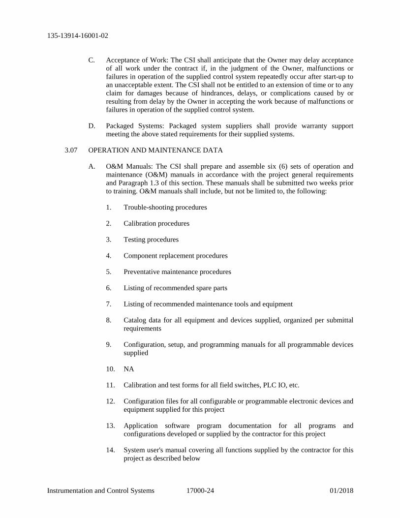
3.07 OPERATION AND MAINTENANCE DATA
A. O&M Manuals: The CSI shall prepare and assemble six (6) sets of operation and maintenance (O&M) manuals in accordance with the project general requirements and Paragraph 1.3 of this section. These manuals shall be submitted two weeks prior to training. O&M manuals shall include, but not be limited to, the following:
1. Trouble-shooting procedures
2. Calibration procedures
3. Testing procedures
4. Component replacement procedures
5. Preventative maintenance procedures
6. Listing of recommended spare parts
7. Listing of recommended maintenance tools and equipment
8. Catalog data for all equipment and devices supplied, organized per submittal requirements
9. Configuration, setup, and programming manuals for all programmable devices supplied
10. NA
11. Calibration and test forms for all field switches, PLC IO, etc.
12. Configuration files for all configurable or programmable electronic devices and equipment supplied for this project
13. Application software program documentation for all programs and configurations developed or supplied by the contractor for this project
14. System user's manual covering all functions supplied by the contractor for this project as described below

135-13914-16001-02
Instrumentation and Control Systems 17000-25 01/2018
B. Record Documents: All contract P&ID drawings and control strategy specification sections and all submittal drawings shall be revised to reflect as-built conditions at the end of the project. Record drawings and documents shall be submitted in accordance with the project general requirements and Paragraph 1.3 of this section. Record drawings and documents shall be submitted with the O&M manuals. Record drawings and documents shall include the following:
1. Shop drawings per 1.7 of this section.
2. Wiring diagrams of cabinet and enclosure contained assemblies
3. Wiring diagrams of all system connections and interconnections including all loops, field equipment, communications interfaces, networks, etc.
4. All other submitted shop and installation drawings and details not listed
5. Bill of Material
6. Contract P&ID drawings
7. Contract control strategy specification sections
3.08 SYSTEM USERS MANUAL
A. Scope: The CSI shall develop and submit a detailed user manual covering all aspects of the operation and use of the components and systems they supply. The manual shall cover the following
1. Overview: An overview of the valve system and how it works
2. Network scheme: Provide IP address listing
3. Security: System, application, remote access, etc., security. Provide all configured user and administrator user names and passwords.
4. Start-Up: System start-up procedures for SCADA systems supplied and configured by the contractor for the project.
B. Used in Training: NA
C. Packaged Equipment: Packaged equipment suppliers shall supply user's manuals per the above requirements for the systems they supply.
D. Third Party Programming: NA
3.09 TRAINING
A. General: The CSI shall conduct specifically an organized training sessions to educate and train the Owner's personnel in the maintenance and operation of the Valve System.

135-13914-16001-02
Instrumentation and Control Systems 17000-26 01/2018
1. All O&M manual items
2. All system users’ manual items
B. Training Sessions: The CSI shall provide a minimum of 4 hours of on-site instruction to the Owner's employees after start-up and commissioning of the system. The Owner shall be allowed to video tape all or any part of the training sessions. The CSI shall prepare and assemble specific instruction materials for the training session and shall supply such materials to the Project Representative at least two (2) weeks prior to the time of the training. The O&M manuals and the system users’ manual shall be complete and shall be used in the training sessions.
END OF SECTION 17000

135-13914-16001-02
Computer Equipment 17220-1 01/2018
SECTION 17220 COMPUTER EQUIPMENT
1. GENERAL
1.01 DESCRIPTION OF WORK
A. Scope: This section specifies requirements for computer components and systems.
B. Related Sections: N/A
C. Performance Benchmarks: Items listed by part number are intended to serve as performance benchmarks. Submit most current model meeting the benchmark performance requirements for items that have been superseded or are otherwise obsolete.
D. Not all products listed are required for all applications. Submit only products required for the application.
1.02 QUALITY ASSURANCE
A. Listing:
1. All materials and equipment specified herein shall be within the scope of Nationally Recognized Testing Laboratory (NRTL) examination services, be approved by the NRTL for the purpose for which they are used, and shall bear the appropriate listing/label.
2. Equipment listed/labeled by an NRTL acceptable to the local authority having jurisdiction.
3. When a product is not available with a listing/label for the purpose for which it is to serve, the product may be required by the inspection authority to undergo a special inspection at the manufacturer’s place of assembly or as a completed assembly in the field. All costs and expenses incurred for such inspections shall be included in the original contract price.
1.03 SUBMITTALS
A. Per Submittals Section
2. PRODUCTS
2.01 GENERAL
A. Computer system hardware shall be standard commercial off-the-shelf products that meet the specified requirements.
135-13914-16001-02
Computer Equipment 17220-2 01/2018
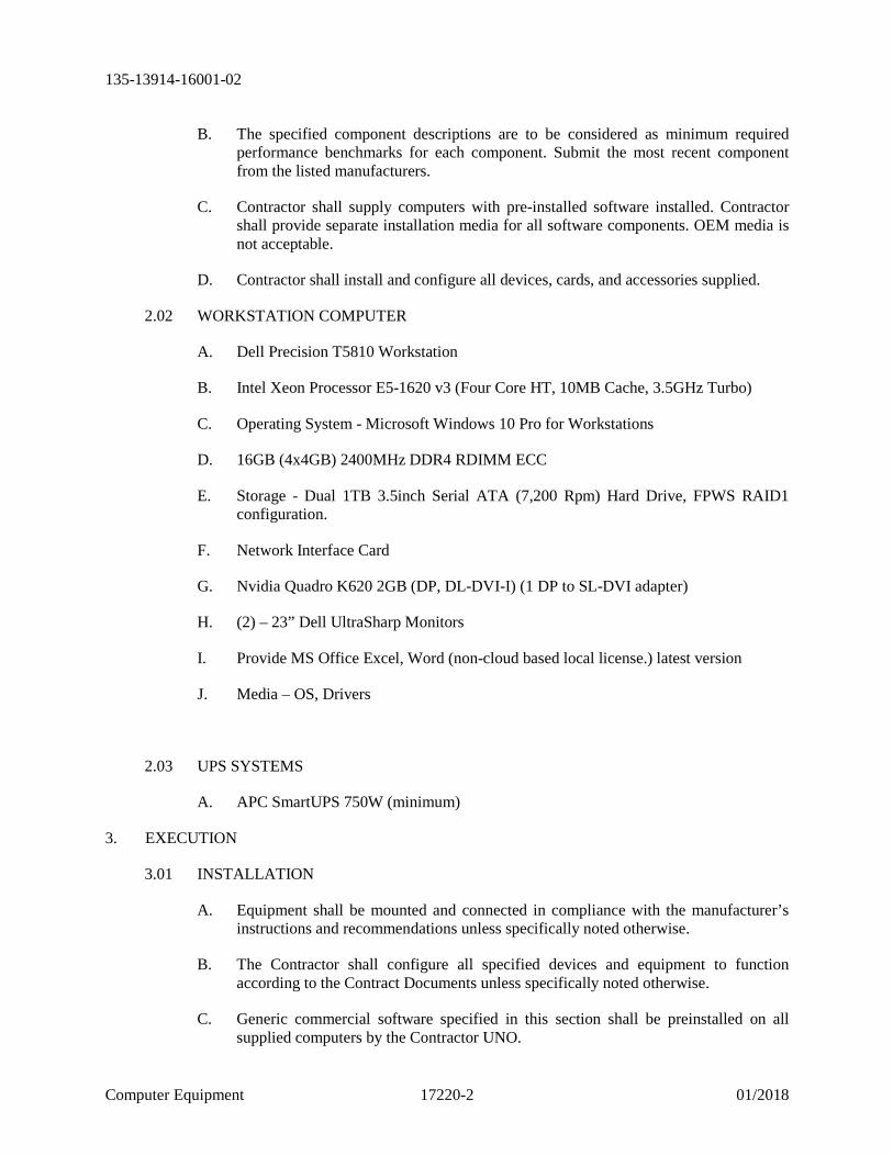
B. The specified component descriptions are to be considered as minimum required performance benchmarks for each component. Submit the most recent component from the listed manufacturers.
C. Contractor shall supply computers with pre-installed software installed. Contractor shall provide separate installation media for all software components. OEM media is not acceptable.
D. Contractor shall install and configure all devices, cards, and accessories supplied.
2.02 WORKSTATION COMPUTER
A. Dell Precision T5810 Workstation
B. Intel Xeon Processor E5-1620 v3 (Four Core HT, 10MB Cache, 3.5GHz Turbo)
C. Operating System - Microsoft Windows 10 Pro for Workstations
D. 16GB (4x4GB) 2400MHz DDR4 RDIMM ECC
E. Storage - Dual 1TB 3.5inch Serial ATA (7,200 Rpm) Hard Drive, FPWS RAID1 configuration.
F. Network Interface Card
G. Nvidia Quadro K620 2GB (DP, DL-DVI-I) (1 DP to SL-DVI adapter)
H. (2) – 23” Dell UltraSharp Monitors
I. Provide MS Office Excel, Word (non-cloud based local license.) latest version
J. Media – OS, Drivers
2.03 UPS SYSTEMS
A. APC SmartUPS 750W (minimum)
3. EXECUTION
3.01 INSTALLATION
A. Equipment shall be mounted and connected in compliance with the manufacturer’s instructions and recommendations unless specifically noted otherwise.
B. The Contractor shall configure all specified devices and equipment to function according to the Contract Documents unless specifically noted otherwise.
C. Generic commercial software specified in this section shall be preinstalled on all supplied computers by the Contractor UNO.
135-13914-16001-02
Computer Equipment 17220-3 01/2018
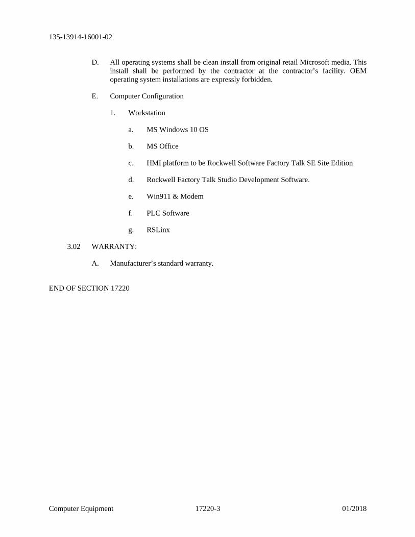
D. All operating systems shall be clean install from original retail Microsoft media. This install shall be performed by the contractor at the contractor’s facility. OEM operating system installations are expressly forbidden.
E. Computer Configuration
1. Workstation
a. MS Windows 10 OS
b. MS Office
c. HMI platform to be Rockwell Software Factory Talk SE Site Edition
d. Rockwell Factory Talk Studio Development Software.
e. Win911 & Modem
f. PLC Software
g. RSLinx
3.02 WARRANTY:
A. Manufacturer’s standard warranty.
END OF SECTION 17220

135-13914-16001-02
Fuctional System Specifcations 17501-1 01/2018
SECTION 17501 FUNCTIONAL SYSTEM SPECIFICATIONS
1. GENERAL
1.01 DESCRIPTION OF WORK
A. This Section specifies requirements for functionality of the system to be installed as a part of this contract.
1.02 QUALITY ASSURANCE
A. Referenced Standards: This Section incorporates by reference the latest revision of the documents listed below.
1. PLC Open Foundation
2. IEC 61131-3
1.03 SUBMITTALS
A. General: Per Submittals Section.
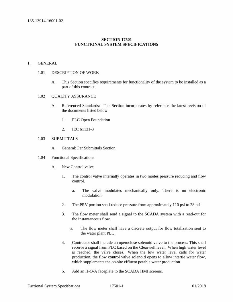
1.04 Functional Specifications
A. New Control valve
1. The control valve internally operates in two modes pressure reducing and flow control.
a. The valve modulates mechanically only. There is no electronic modulation.
2. The PRV portion shall reduce pressure from approximately 110 psi to 28 psi.
3. The flow meter shall send a signal to the SCADA system with a read-out for the instantaneous flow.
a. The flow meter shall have a discrete output for flow totalization sent to the water plant PLC.
4. Contractor shall include an open/close solenoid valve to the process. This shall receive a signal from PLC based on the Clearwell level. When high water level is reached, the valve closes. When the low water level calls for water production, the flow control valve solenoid opens to allow intertie water flow, which supplements the on-site effluent potable water production.
5. Add an H-O-A faceplate to the SCADA HMI screens.
135-13914-16001-02
Fuctional System Specifcations 17501-2 01/2018
a. In “Hand”: The flow control valve solenoid shall open, allowing continuous filling of the Clearwell at the preset flow rate and independent of process control production “call” status.
b. In “Off”: Flow control valve solenoid shall remain closed regardless of Clearwell level or water production calls.
c. In “Auto”: The flow control valve solenoid shall open automatically whenever the plant control system calls for water production, allowing for the plant water production to be supplemented at the predetermined flow rate of the flow control valve.
B. SCADA improvements
1. Duplicate existing functionality into latest version of FactoryTalk View Site Edition per SCADA specification.
END OF SECTION 17501
135-13914-16001-02
Supervisory Control and Data Acquisition 17801-1 01/2018 (SCADA) System
SECTION 17801 SUPERVISORY CONTROL AND DATA ACQUISITION (SCADA) SYSTEM
1. GENERAL
1.01 DESCRIPTION OF WORK
A. Scope: This section specifies software components of the Supervisory Control and Data Acquisition system.
B. The SCADA server environment shall be a Station Application
C. Software components and licenses for the SCADA system include, but are not limited to the following:
1. MS Office suite products
2. SCADA application software
3. PLC system software
4. Remote SCADA access software
5. Dialer Software
1.02 QUALITY ASSURANCE
A. All products shall be commercial off the shelf products. All products shall be provided by manufacturers with the highest possible reputation in the industry for the application. Custom products are not acceptable. All products supplied shall be either provided by a single manufacturer or shall be endorsed by all the manufacturers for integration into a complete, fully functional, and reliable system. All components, if not the product of a single manufacturer, shall be recommended by all of the component manufacturers for integration with all other provided software products supplied.
B. It shall be the CSI's responsibility to verify that all submitted software components of the system meet the support requirements of all of the system software vendors. This applies particularly to computer operating system compatibility.
C. Acceptability of submitted products shall be entirely at the discretion of the project.
1.03 SUBMITTALS
A. Software list Bill of Materials (BOM) to be submitted per requirements submittals section
135-13914-16001-02
Supervisory Control and Data Acquisition 17801-2 01/2018 (SCADA) System
B. Submittal to include Manufacturer’s version and revision number for each software component.
C. Provide Manufacturer’s product data sheets for each software component.
D. Include software licenses as separate line-items within the BOM. All installed licenses shall be fully activated, and shall not deactivate after any trial-period time.
E. Include Information regarding Manufacturer’s software support including hotline technical support numbers and phone numbers to suppliers.
2. PRODUCTS
2.01 GENERAL
A. All software components shall be commercial off the shelf type components which have not been customized for the application. All components, programs, configurations, etc., shall be non-proprietary with no legal restrictions on their use or modification.
B. All software licensing requirements are specified by the functions they must enable and by the number of concurrent running instances of the software they allow. The contractor shall submit software licenses which meet the listed functional requirements as a minimum. The functionality of the submitted licenses shall be greater than or equal to the specified functionality.
C. The contractor shall provide any and all ancillary or related software and licensing required to support the specified functionality of the core software components. These items shall be considered incidental to and included in the contract.
2.02 SCADA APPLICATION SOFTWARE:
A. General: SCADA software core components shall be Rockwell Automation Factory Talk View Site Edition, most current version at the time of purchase.
B. All licenses required to provide the defined functionality shall be provided. It shall be the CSI's responsibility to determine, submit, and supply the required licenses. SCADA software licenses provided shall license a minimum of 100 screens. Hot Backup SCADA fail over is not required.
C. Remote Access SCADA:
1. (4) Remote SCADA Connections shall be provided via PC and (4) Mobile. (2) will be supplied to the Cities System Integrator for Remote services.
D. SCADA HMI development licenses: The contractor shall provide sufficient software licenses to support 1 Development System.
E. Data Acquisition: Shall be Factory Talk RSLinx
135-13914-16001-02
Supervisory Control and Data Acquisition 17801-3 01/2018 (SCADA) System
E. SCADA process data base: NA
G. Process Data Historian Software: NA
H. Data Reporting Utilities: NA
I. Remote Alarm Notification Software
1. Software shall integrate with the SCADA software and provide greater than 3 levels of alarm annunciation including the use of voice, phone, pager, e-mail, and support of alarm groups with common acknowledgement indication across all SCADA nodes.
2. Software shall be WIN911, with FT Connection: no substitutions.
3. The alarm software shall be the software product most highly recommended by the SCADA software manufacturer.
4. Contractor shall provide 1 Professional Version
5. Contractor shall provide and configure modem(s) specified by Win911 for use with the software.
J. SOFTWARE PACKAGES TO SUPPLY – Latest Versions to run on Windows 10
a) (1) - Factory Talk View SE Station 100 Display
b) (1) - Factory Talk View Studio SE
c) (1) – RS Logix 500 Standard
d) (1) – RSLinx Gateway
e) (1) – Win-911 Interactive (PRO)
f) (1) – Win-911 FT Connection
g) (1) – Win-911 USB Modem
3. EXECUTION
3.01 INSTALLATION
A. The Contractor shall install and configure all software supplied unless specifically noted otherwise.
135-13914-16001-02
Supervisory Control and Data Acquisition 17801-4 01/2018 (SCADA) System
3.02 PROGRAMMING AND CONFIGURATION:
A. Contractor shall install, configure, program, and test all SCADA application and related software specifications unless specifically noted otherwise.
B. Screens shall be developed or otherwise migrated as a like-in-kind interface, except for the software platform upgrade and the addition of a flow control valve H-O-A faceplate and intertie flow indicator faceplate.
1. Use new Graphics Library of existing and layout including all P&ID information
2. Incorporate all user interfaces, faceplates, displays, alarms, and animations as required to duplicate existing HMI screens. Provide tag substitution tables where required for faceplate mapping to field device parameters if used in existing HMI software.
3. Test and verify all HMI points, tags, and functional operation within the system, end-to-end.
4. Configure and test alarm call-out (WIN911) software to mimic existing functionality.
3.03 TESTS AND INSPECTIONS
A. Per tests and inspections specification
3.04 OPERATION AND MAINTENANCE DATA
A. The Contractor shall provide complete sets of documentation for all software components supplied.
B. Documentation sets shall include installation manuals, user manuals, technical manuals, troubleshooting manuals, etc.
C. Original documents or copies of originals shall be required. Internet or web page printouts shall not be accepted.
D. High volume documentation may be provided on electronic storage media. Provide bookmark index of documentation.
E. The contractor shall develop and provide a comprehensive and detailed SCADA system user’s manual per Instrumentation and Control specifications.
END OF SECTION 17801
135-13914-16001-02
Programming 17802-1 01/2018
SECTION 17802 PROGRAMMING
1. GENERAL
1.01 DESCRIPTION OF WORK
A. This Section specifies requirements for programming software, programmable devices, and programmable systems.
B. Provide fully operational, fully programmed, and fully tested programs for all supplied programmable devices, software, and systems unless specifically noted otherwise. All programming shall become property of the Owner.
C. Programming for controlled processes shall replicate existing functionality, using updated software and hardware platforms. Include setup, configuration and programming of all programmable items furnished under this Contract including, but not limited to:
1. PLC's
2. Data acquisition servers
3. SCADA system components
4. Telemetry hardware and network components
5. Remote alarm notification software
6. Other programmable devices supplied but not listed above
D. Version Compatibility: Contractor shall utilize the latest (most up to date) hardware, software and firmware versions that are fully compatible and tested for interoperability as recommended by the individual device and/or software Manufacturers. Update or roll-back versions as applicable to support required software installation and programming.
E. Develop fully documented and updated programming by migrating or otherwise creating programming code as required to re-implement existing functionality on the updated platforms. This programming shall include all salient features and functions as depicted and/or described in specifications and drawings.
F. Experience: Programmers responsible for performing the detailed software design and programming of programmable equipment on the project shall have a minimum of five (5) years of experience in similar projects. The Contractor shall assume full responsibility for software system design, programming, and operation unless specifically noted otherwise.
135-13914-16001-02
Programming 17802-2 01/2018
G. Acceptable Programmers: All programming on the project shall be provided by either a direct employee of the CSI, packaged equipment control system suppliers, or the design consultant. CSI employees providing programming services to the project shall have a minimum of 1 year of employment with the CSI. Packaged equipment suppliers shall provide programming for supplied programmable packaged control system components. The design consultant may be hired to program CSI supplied equipment. Contract programmers hired by the contractor or the CSI are not acceptable
1.02 QUALITY ASSURANCE
A. Referenced Standards: This Section incorporates by reference the latest revision of the documents listed below.
1. PLC Open Foundation
2. IEC 61131-3
1.03 SUBMITTALS
A. Progress Submittals: All programming elements shall be submitted to the Project Representative for review at all required submittal levels.
B. Format: Submit as hard copy printed program and configuration listings as well as programming software file format on CD-ROM.
C. Submittals: Submittals shall include the following as they apply to this project and the submittal level as defined within Part 3 - Execution:
1. PLC logic block diagrams
2. PLC I/O and data file listings
3. PLC program listings
4. PLC program files
5. SCADA HMI screen and functionality samples from recent similar project
6. SCADA database listing
7. SCADA HMI screenshots
8. SCADA HMI program files
9. Remote alarm notification software database listing
10. Remote alarm notification software configuration files
D. SCADA: Submit color "screen shot" images of each proposed SCADA screen.

135-13914-16001-02
Programming 17802-3 01/2018
1.04 PROGRAMMING SOFTWARE
A. PLC programming software as specified in programming specifications.
B. SCADA programming software as specified.
C. Remote alarm notification software as specified.
1.05 PLC PROGRAMMING
A. General: All programmed process and equipment control logic shall be executed in PLC’s. The Contractor shall have full and complete knowledge of ladder logic programming. PLC programming is existing to remain with exception of the added analog flow meter input and discrete FCV control output (with associated H-O-A faceplate logic.)
B. PLC logic shall be modified in the existing SLC5/05 PLC to interface with analog and discrete points added under this project. Discrete output to valve solenoid shall actuate when PLC program calls for water production and delivery to Clearwell to begin.
C. Ladder Logic: Program all PLC functions in Ladder Logic. Submit requests to program functions in any other language. Function Block, Structured Text, and Sequential Function Chart programming may be allowed on an exception basis with written permission from the project representative. Time spent by the Contractor to correct programming that is not compliant with the programming software and programming language defined in this section will be at the Contractor's expense and shall not affect the project schedule or milestone dates.
1.06 SOFTWARE REVISIONS
A. Revision Tracking: Provide a formal revision tracking procedure for all software being developed and submitted to the Project Representative. The revision tracking procedure shall contain information necessary to track all changes, and ensure revisions are properly tested, documented, and incorporated into the final program. The revision tracking procedure shall track submitted programs, reference Project Representative's comments, show date program was saved, date of all revisions, and reference to material used for the program revisions. The revision tracking procedure shall ensure that only fully tested, fully documented, and properly revised software is loaded into the PLC for delivery. Track incorporation of reviewers comments.
1.07 COMMUNICATIONS
A. Ethernet: PLC, SCADA components shall communicate over the plant process control Ethernet network.
1.08 PROGRAM DEVELOPMENT AND COMMISSIONING RESPONSIBILITY
A. General: The contract documents include depictions and descriptions of the functional requirements of control system component programming. Unless
135-13914-16001-02
Programming 17802-4 01/2018
specifically noted otherwise the contractor shall configure and program all programmable equipment on the project. The contractor shall in all cases be responsible for the proper functioning or all programmable hardware they supply. The contractor shall in all cases be responsible for the process control network, communication systems, media, and infrastructure on which proper process control programming functionality depends.
B. Network Devices: The Contractor is required to configure specifically identified network devices which provide network connectivity to the owner's network and IT systems. These items include the following devices:
1. Alarm dial-out peripherals
2. PRODUCTS
2.01 PROGRAMS
A. General: Provide fully functioning programs that are without error, do not perform abnormal stops or actions, and are fully documented.
B. Security: Per Existing System
C. Graphic Screen Content: Operator Interface and HMI display screens shall provide the following types of information:
1. System Overview
2. Sub process detailed information
3. Equipment Status
4. Set point and Data Entry
5. Alarm History with time/date stamp
6. Control Modes and logic state
7. Maintenance information
8. Trends
9. Navigation
D. Graphic Screen Layout
1. Graphic displays shall include static and animated text and graphical representations of the facility, the equipment, and the process.
2. Graphic HMI displays shall be logical, well organized, and intuitive to the operators. Do not overpopulate and congest screens. Create a sufficient number
135-13914-16001-02
Programming 17802-5 01/2018
of screens to provide easy to read and understand screens which logically separate process information.
3. Graphic elements shall resemble the facilities, equipment, and devices they represent. Use manufacturer provided graphic elements where available.
4. Replicate existing Owner screens and layout.
5. Include color scheme, aminations, user interfaces, security log-ins/permissions level, and navigation to match existing HMI screens.
2.02 SOFTWARE FUNCTIONS
A. PLC Programs: Provide PLC programs capable of performing the following general functions at a minimum:
1. Develop PLC programs to expand existing logic and I/O interface.
B. HMI: SCADA HMI programming that allows adjustment of loop set points, timer and counter presets, loop tuning parameters, etc.
2.03 PROGRAM DOCUMENTATION
A. General: Provide complete documentation of all programs. Utilize available documentation services available through the Programming Software. Application programs shall be fully documented. Program databases shall be fully expanded and documented and shall include a populated comments field. Documentation shall be sufficiently thorough to enable reviewers to review and understand all submitted programs without extensive reverse engineering efforts, and to enable trained staff of the owner to review, understand, maintain, and modify programs supplied without extensive reverse engineering efforts. Programming components required to be complete for each progress submittal level shall be fully documented.
B. PLC Programs: For New logic, Document PLC programs. Apply comments to describe program blocks, sub programs, ladder rungs, and instructions. Provide descriptive program block, sub program, and rung comments which relate the programming to the control sequence specifications. Provide sufficiently detailed comments to enable reviewers to understand the logic flow and functions of the programs. Use sub program and rung comments to explain how the code performs the all functions including those specified in the control strategy specification sections. Provide revision history of programs. Submit complete printouts and files demonstrating compliance to documentation requirements.
C. Tag Names: Provide consistent tag names in PLC, SCADA, and remote alarm notification software. Tags shall be descriptive and correlate to the loop, equipment, or function to which they are associated. Include device or equipment tag number in register tag names, instruction comments, and rung comments at every available opportunity where the application of the element is specific to an individual tag number. Utilize existing tags for field devices and equipment where applicable.
135-13914-16001-02
Programming 17802-6 01/2018
D. Descriptor Fields: Fully utilize all descriptor fields provided by the programming software including the following:
1. Tags and Aliases
2. Descriptions
3. Comments
4. Titles
E. Data Communications
1. Packaged Equipment: Provide documentation detailing data structures communicated between vendor and contractor provided PLC's and SCADA. Provide correlated tag lists from vendor provided PLC's or SCADA which exchange data with contractor provided PLC's or SCADA.
2.04 OWNERSHIP OF SOFTWARE LICENSES AND PROGRAMS
A. All operating software, programming software, etc. shall become the property of the Owner upon completion of the project. Suppliers and contractors shall make no claims of ownership, copyright, or other licenser upon final acceptance of the system. All “Commercial” software licenses required shall be licensed to the Owner at the time of the original purchase.
3. EXECUTION
3.01 PROGRAM DEVELOPMENT
A. Schedule: Provide a schedule showing program development tasks including milestones. Include all software programs developed by the contractor. The schedule shall include the following steps as a minimum:
1. Predevelopment coordination Meeting
2. Preliminary Software Submittal (50%)
3. Final Software Submittal with O&M manuals (100%)
4. Submittal review meetings
B. Predevelopment Coordination: The programmer shall coordinate with the project prior to the start of detailed program development. The programmer shall provide the project with examples of proposed conventions, function implementation, and data presentations as requested by the project. The Project may at their discretion provide the programmer with samples of software functions and data presentations, conventions, etc. The programmer shall incorporate requested software functions, data presentations, conventions, etc. into the programs they develop.
135-13914-16001-02
Programming 17802-7 01/2018
C. Submittals: Provide submittals listed below. Submit in programming software configuration and program file format and hardcopy format. Hard copy shall be produced with utilities provided with the programming software or format shall be compatible with Microsoft Word/Excel 2010®. All program and configuration files shall be represented at each submittal level and shall be submitted simultaneously for each submittal level. Resubmittal of any programming submittal level may be required or may be deferred to the next submittal level at the discretion of the owners Project Representative. Resubmittals shall be provided upon the request of the owners Project Representative until the owners Project Representative approves all elements of the programming and configuration submittals.
1. Predevelopment Submittal: Submit HMI screen samples from recent similar projects. Submit proposed standard screen element color code and proposed standard graphic elements for interface screen presentations.
2. 50% Software Submittal: Submit all items listed under submittals developed to a 50% level of completion. All unique functional and presentation elements shall be identified. All functional and presentation elements shall be identified and associated with a defined unique functional element. Tag databases shall be complete for all unique functional and presentation elements at the 30% level. A list shall be provided which identifies the duplication of the developed tags required to complete the tag databases. Programming for 50% of all unique functional and presentation elements shall be complete at the 30% submittal level. Programming for 50% of all functional and presentation elements shall be complete at the 50% submittal level. A list shall be provided which indicates all remaining functional and presentation elements to be developed and identifies which block of common tags and programming will be duplicated to complete the programming. Include tag lists and communications device configurations for data acquired via Devicenet, Foundation Fieldbus, vendor-provided PLC's or SCADA, etc.
3. 100% Submittal: Submit completed programs to be used for factory acceptance testing.
4. O&M Submittal: Submit final programs and documentation as part of O&M manuals.
D. Submittal Review: The programmer shall provide progress submittals listed above to the project in the specified formats, color screen shots, and as requested by the project for review by the project. The project will provide review comments to the programmer. The programmer shall incorporate all project submittal review comments into the development of the subsequent submittal as requested by the project. The contractor shall attend a submittal review and coordination meeting following each submittal. The meetings shall be at a time and place and of a duration required by the project. The project may, at its discretion, waive any or all of the submittal review meetings.
135-13914-16001-02
Programming 17802-8 01/2018
E. Contractor Response to Submittal Review Comments: The contractor shall provide individual written responses to each submittal review comment on a file copy of the submittal review comments and shall submit these responses and the updated and corrected files with the subsequent submittal. Responses to submittal review comments shall describe the action taken to correct or otherwise address the issue identified by each submittal review comment. Responses such as "comment noted", "will review and correct as needed", etc., are not acceptable. The review comment responses shall identify all specific areas of the program and configuration files that have been modified in response to the review comments. The review comment responses shall be accompanied by the updated programming and configuration files which contain the corrections as referenced by the review comment responses and as required by the submittal level requirements.
F. Coordination of Display Screen Development
1. General: Coordination of all HMI devices and programming shall be within the Contractors scope of supply UNO. This includes CSI provided systems and bid and assigned Vendor provided systems. The development of display screens for these systems shall be coordinated with the Project Representative to ensure consistency of functionality and the look and feel of the systems at the plant.
2. Screen Content: Match existing with exception of added faceplates and indicators.
3. Screen Conventions: Display screens shall follow the Owners conventions for color usage, function, navigation, alarm display, graphic symbols, animation, etc. if requested. The Contractor shall coordinate display screen presentation development with the Project Representative and shall submit tag lists, alarm lists, PLC I/O lists, sample screens, color code, etc., to the Project Representative for approval.
3.02 DETAILED HMI PROGRAMMING REQUIREMENTS:
A. Match existing screens, virtual controls, animations, etc. in new HMI platform. Add tag and on-screen faceplate for Intertie Flow meter analog display.
3.03 PROGRAM INSTALLATION
A. The Contractor is responsible for obtaining, loading and configuring all software and application programs applicable to this project.
B. Coordinate with the Owner’s designated IT Personnel for establishing port availability and network addressing details. Provide the Owner with a list of requested IP addresses, and port connections.
C. Install the application program.
D. Edits by the Contractor to software installed in a PLC in production operation at the facility shall comply with the following:
135-13914-16001-02
Programming 17802-9 01/2018
1. Coordinate the changes, edits or reloading of the programs with the Project Representative.
2. The Project Representative shall approve all changes before loading the program into the PLC.
3. All programming changes shall be downloaded locally.
4. Contractor shall provide complete record documents. All applicable documentation, drawings, copies of the program, and narratives shall be revised by the Contractor to reflect the edits to the programs and the operation of the process.
END OF SECTION 17802
