end of well reports for the ou 3-14 2004 tank farm soil ... · ou 3-14 2004 tank farm ... assistant...
TRANSCRIPT

ICP/EXT-04-00706Revision 0
End of Well Reports for the OU 3-14 2004 Tank Farm Soil Investigation at the Idaho Nuclear Technology and Engineering Center
Arden Bailey, PS2 Dean E. Shanklin
April 2006

ICP/EXT-04-00706Revision 0
Project No. 23512
End of Well Reports for the OU 3-14 2004 Tank Farm Soil Investigation at the Idaho Nuclear Technology
and Engineering Center
Arden Bailey, PS2 Dean E. Shanklin
April 2006
Idaho Cleanup Project
Idaho Falls, Idaho 83415
Prepared for the U.S. Department of Energy
Assistant Secretary for Environmental Management Under DOE Idaho Operations Office
Contract DE-AC07-05ID14516

iii
ABSTRACT
Twenty-three boreholes and probeholes were drilled for subsurface characterization and sampling purposes within the Idaho Nuclear Technology and Engineering Center in support of the Operable Unit 3-14 Tank Farm Soils and Groundwater Remedial Investigation/Feasibility Study in the summer of 2004. Downhole gamma-logging data collected from within the existing and new probeholes will be used to determine the aerial extent of contamination within the subsurface soils. Analytical data collected from five sample boreholes drilled to refusal or basalt will be used to determine the compositional characteristics and migration of the contamination, to support the conceptual model, and to confirm source term assumptions. This report documents the field installation of these 23 boreholes and probeholes, the sample collection, and the gamma logging of the existing and new probeholes.

iv

v
CONTENTS
ABSTRACT................................................................................................................................................. iii
ACRONYMS............................................................................................................................................... xi
1. INTRODUCTION...........................................................................................................................1-1
1.1 Site Description and Background.......................................................................................1-1
1.2 Logging of New and Pre-existing Probeholes....................................................................1-4
1.3 Sampling of Locations........................................................................................................1-8
2. 15-1 (CPP-1866) END OF WELL REPORT ..................................................................................2-1
2.1 General ...............................................................................................................................2-1
2.2 Drilling and Completion Observations...............................................................................2-1
2.2.1 Drilling Activity ...............................................................................................2-1 2.2.2 Problems Encountered and Lessons Learned...................................................2-2 2.2.3 Gamma Logging...............................................................................................2-2 2.2.4 Sampling ..........................................................................................................2-2
3. 15-2 (CPP-1867) END OF WELL REPORT ..................................................................................3-1
3.1 General ...............................................................................................................................3-1
3.2 Drilling and Completion Observations...............................................................................3-1
3.2.1 Drilling Activity ...............................................................................................3-1 3.2.2 Problems Encountered and Lessons Learned...................................................3-2 3.2.3 Gamma Logging...............................................................................................3-2 3.2.4 Sampling ..........................................................................................................3-2
4. 15-3 (CPP-1868) END OF WELL REPORT ..................................................................................4-1
4.1 General ...............................................................................................................................4-1
4.2 Drilling and Completion Observations...............................................................................4-1
4.2.1 Drilling Activity ...............................................................................................4-1 4.2.2 Problems Encountered and Lessons Learned...................................................4-2 4.2.3 Gamma Logging...............................................................................................4-2 4.2.4 Sampling ..........................................................................................................4-2
5. 15-SAMPLE (CPP-1869) END OF WELL REPORT ....................................................................5-1
5.1 General ...............................................................................................................................5-1

vi
5.2 Drilling and Completion Observations...............................................................................5-1
5.2.1 Drilling Activity ...............................................................................................5-1 5.2.2 Problems Encountered and Lessons Learned...................................................5-2 5.2.3 Gamma Logging...............................................................................................5-2 5.2.4 Sampling ..........................................................................................................5-2
6. 27-1 (CPP-1870) END OF WELL REPORT ..................................................................................6-1
6.1 General ...............................................................................................................................6-1
6.2 Drilling and Completion Observations...............................................................................6-1
6.2.1 Drilling Activity ...............................................................................................6-1 6.2.2 Problems Encountered and Lessons Learned...................................................6-2 6.2.3 Gamma Logging...............................................................................................6-2 6.2.4 Sampling ..........................................................................................................6-2
7. 27-SAMPLE-A (CPP-1871) END OF WELL REPORT ................................................................7-1
7.1 General ...............................................................................................................................7-1
7.2 Drilling and Completion Observations...............................................................................7-1
7.2.1 Drilling Activity ...............................................................................................7-1 7.2.2 Problems Encountered and Lessons Learned...................................................7-2 7.2.3 Gamma Logging...............................................................................................7-2 7.2.4 Sampling ..........................................................................................................7-2
8. 27-SAMPLE-B (CPP-1872) END OF WELL REPORT ................................................................8-1
8.1 General ...............................................................................................................................8-1
8.2 Drilling and Completion Observations...............................................................................8-1
8.2.1 Drilling Activity ...............................................................................................8-1 8.2.2 Problems Encountered and Lessons Learned...................................................8-2 8.2.3 Gamma Logging...............................................................................................8-2 8.2.4 Sampling ..........................................................................................................8-2
9. 27-Sample-C (CPP-1873) END OF WELL REPORT ....................................................................9-1
9.1 General ...............................................................................................................................9-1
9.2 Drilling and Completion Observations...............................................................................9-1
9.2.1 Drilling Activity ...............................................................................................9-1 9.2.2 Problems Encountered and Lessons Learned...................................................9-2 9.2.3 Gamma Logging...............................................................................................9-2 9.2.4 Sampling ..........................................................................................................9-2

vii
10. 28-1 (CPP-1876) END OF WELL REPORT ................................................................................10-1
10.1 General .............................................................................................................................10-1
10.2 Drilling and Completion Observations.............................................................................10-1
10.2.1 Drilling Activity .............................................................................................10-1 10.2.2 Problems Encountered and Lessons Learned.................................................10-2 10.2.3 Gamma Logging.............................................................................................10-2 10.2.4 Sampling ........................................................................................................10-2
11. 28-2 (CPP-1877) END OF WELL REPORT ................................................................................11-1
11.1 General .............................................................................................................................11-1
11.2 Drilling and Completion Observations.............................................................................11-1
11.2.1 Drilling Activity .............................................................................................11-1 11.2.2 Problems Encountered and Lessons Learned.................................................11-2 11.2.3 Gamma Logging.............................................................................................11-2 11.2.4 Sampling ........................................................................................................11-2
12. 28-SAMPLE (CPP-1878) END OF WELL REPORT ..................................................................12-1
12.1 General .............................................................................................................................12-1
12.2 Drilling and Completion Observations.............................................................................12-1
12.2.1 Drilling Activity .............................................................................................12-1 12.2.2 Problems Encountered and Lessons Learned.................................................12-2 12.2.3 Gamma Logging.............................................................................................12-2 12.2.4 Sampling ........................................................................................................12-2
13. 31-1 (CPP-1874) END OF WELL REPORT ................................................................................13-1
13.1 General .............................................................................................................................13-1
13.2 Drilling and Completion Observations.............................................................................13-1
13.2.1 Drilling Activity .............................................................................................13-1 13.2.2 Problems Encountered and Lessons Learned.................................................13-2 13.2.3 Gamma Logging.............................................................................................13-2 13.2.4 Sampling ........................................................................................................13-2
14. 31-SAMPLE (CPP-1875) END OF WELL REPORT ..................................................................14-1
14.1 General .............................................................................................................................14-1
14.2 Drilling and Completion Observations.............................................................................14-1
14.2.1 Drilling Activity .............................................................................................14-1 14.2.2 Problems Encountered and Lessons Learned.................................................14-2

viii
14.2.3 Gamma Logging.............................................................................................14-2 14.2.4 Sampling ........................................................................................................14-2
15. 79-2 (CPP-1886) END OF WELL REPORT ................................................................................15-1
15.1 General .............................................................................................................................15-1
15.2 Drilling and Completion Observations.............................................................................15-1
15.2.1 Drilling Activity .............................................................................................15-1 15.2.2 Problems Encountered and Lessons Learned.................................................15-2 15.2.3 Gamma Logging.............................................................................................15-2 15.2.4 Sampling ........................................................................................................15-2
16. 79-4 (CPP-1885) END OF WELL REPORT ................................................................................16-1
16.1 General .............................................................................................................................16-1
16.2 Drilling and Completion Observations.............................................................................16-1
16.2.1 Drilling Activity .............................................................................................16-1 16.2.2 Problems Encountered and Lessons Learned.................................................16-2 16.2.3 Gamma Logging.............................................................................................16-2 16.2.4 Sampling ........................................................................................................16-2
17. 79-5 (CPP-1884) END OF WELL REPORT ................................................................................17-1
17.1 General .............................................................................................................................17-1
17.2 Drilling and Completion Observations.............................................................................17-1
17.2.1 Drilling Activity .............................................................................................17-1 17.2.2 Problems Encountered and Lessons Learned.................................................17-2 17.2.3 Gamma Logging.............................................................................................17-2 17.2.4 Sampling ........................................................................................................17-2
18. 79-6 (CPP-1887) END OF WELL REPORT ................................................................................18-1
18.1 General .............................................................................................................................18-1
18.2 Drilling and Completion Observations.............................................................................18-1
18.2.1 Drilling Activity .............................................................................................18-1 18.2.2 Problems Encountered and Lessons Learned.................................................18-2 18.2.3 Gamma Logging.............................................................................................18-2 18.2.4 Sampling ........................................................................................................18-2
19. 79-8 (CPP-1888) END OF WELL REPORT ................................................................................19-1
19.1 General .............................................................................................................................19-1

ix
19.2 Drilling and Completion Observations.............................................................................19-1
19.2.1 Drilling Activity .............................................................................................19-1 19.2.2 Problems Encountered and Lessons Learned.................................................19-2 19.2.3 Gamma Logging.............................................................................................19-2 19.2.4 Sampling ........................................................................................................19-2
20. 79-10 (CPP-1883) END OF WELL REPORT ..............................................................................20-1
20.1 General .............................................................................................................................20-1
20.2 Drilling and Completion Observations.............................................................................20-1
20.2.1 Drilling Activity .............................................................................................20-1 20.2.2 Problems Encountered and Lessons Learned.................................................20-2 20.2.3 Gamma Logging.............................................................................................20-2 20.2.4 Sampling ........................................................................................................20-2
21. 79-SAMPLE-A (CPP-1881) END OF WELL REPORT ..............................................................21-1
21.1 General .............................................................................................................................21-1
21.2 Drilling and Completion Observations.............................................................................21-1
21.2.1 Drilling Activity .............................................................................................21-1 21.2.2 Problems Encountered and Lessons Learned.................................................21-2 21.2.3 Gamma Logging.............................................................................................21-2 21.2.4 Sampling ........................................................................................................21-2
22. 79-SAMPLE-B (CPP-1882) END OF WELL REPORT ..............................................................22-1
22.1 General .............................................................................................................................22-1
22.2 Drilling and Completion Observations.............................................................................22-1
22.2.1 Drilling Activity .............................................................................................22-1 22.2.2 Problems Encountered and Lessons Learned.................................................22-2 22.2.3 Gamma Logging.............................................................................................22-2 22.2.4 Sampling ........................................................................................................22-2
23. CPP-1879 END OF WELL REPORT...........................................................................................23-1
23.1 General .............................................................................................................................23-1
24. CPP-1880 END OF WELL REPORT...........................................................................................24-1
24.1 General .............................................................................................................................24-1
25. REFERENCES..............................................................................................................................25-1
Appendix A—Final Downhole Gamma Logs ..........................................................................................A-1

x
Appendix B—Gamma Survey Cross Section (West to East) Through Site CPP-79 and Gamma Survey Cross Section (South to North) Through Sites CPP-79 and CPP-28 ................................ B-1
Appendix C—Gamma-Logging Data for OU 3-14 Tank Farm Investigation for CPP-79 ....................... C-1
Appendix D—Gamma-Logging Data for OU 3-14 Tank Farm Investigation for CPP-15, CPP-27, CPP-28, and CPP-31 ......................................................................................................................D-1
FIGURES
1-1. Location of the Idaho Nuclear Technology and Engineering Center at the Idaho National Laboratory.....................................................................................................................................1-2
1-2. New and existing probeholes and new sample locations ..............................................................1-3
1-3. CPP-28/79 release sites.................................................................................................................1-5
1-4. CPP-31 release sites......................................................................................................................1-6
TABLES
1-1. Probe hole and sample location cross-reference list .....................................................................1-7
1-2. Archived intact intervals ...............................................................................................................1-8
1-3. Archived material (500-mL high-density polyethelene container) ...............................................1-9

xi
ACRONYMS
bls below land surface
FSP field sampling plan
GM Geiger-Mueller
HDR Hydrological Data Repository
HPIL Health Physics Instrument Laboratory
ICP Idaho Completion Project
INEEL Idaho National Engineering and Environmental Laboratory
INL Idaho National Laboratory
INTEC Idaho Nuclear Technology and Engineering Center
OU operable unit
RI/BRA remedial investigation/baseline risk assessment
ROD Record of Decision
SVOC semivolatile organic compound
TAL target analyte list
TCLP toxicity characteristic leaching procedure
VOC volatile organic compound
WAG waste area group

xii

1-1
End of Well Reports for the OU 3-14 2004 Tank Farm Soil Investigation at the
Idaho Nuclear Technology and Engineering Center 1. INTRODUCTION
The activities described in this report were conducted under the Operable Unit 3-14 Tank Farm Soil and Groundwater Remedial Investigation/Feasibility Study Work Plan (DOE-ID 2004a) and the Waste Area Group (WAG) 3, Operable Unit (OU) 3-14 Field Sampling Plan (FSP) (DOE-ID 2004b). The purpose of these activities was to collect environmental data in order to fill the data gaps concerning the extent, distribution, and composition of contamination in soils located at identified release sites at the Idaho Nuclear Technology and Engineering Center (INTEC) tank farm that had been identified in the OU 3-13 Record of Decision (ROD) (DOE-ID 1999). The data collected will support the remedial investigation/baseline risk assessment (RI/BRA) and feasibility study phases of OU 3-14.
This investigation involved a two-phased approach which focused project resources on maximizing uncertainty reductions to meet data quality objectives while minimizing unnecessary sampling and characterization efforts.
The first phase was to install cased probeholes to reduce the uncertainty in the spatial extent and distribution of contaminants at known release sites. All tank farm releases are known to have contained high concentrations of gamma-emitting radionuclides including cesium-137 (Cs-137); therefore, the Phase 1 investigation focused on determining the spatial extent and distribution (e.g., locations of hot spots) of gamma-emitting radionuclides in the release zones. Gamma radiation then served as an indicator of zones where other contaminants of potential concern were most likely to exist.
The second phase was to collect soil samples from the surface to basalt or a specified depth at a selected location within each of the designated release sites. The objective of the sampling effort was to define the composition of contamination from release locations defined during the probing effort or to determine the vertical extent of contamination if previously undefined.
A map indicating locations of the INTEC at the Idaho National Laboratory (INL)a and the tank farm within the INTEC is provided in Figure 1-1.
1.1 Site Description and Background
Probing and sampling activities were conducted in the following soil contamination sites: CPP-15, CPP-27, CPP-28, CPP-31, and CPP-79. With the exception of soil contamination site CPP-15, all the sites are within CPP-96, Tank Farm Soils (Figure 1-2).
a. Beginning February 1, 2005, the name of the Idaho National Engineering and Environmental Laboratory (INEEL) was changed to Idaho National Laboratory (INL). The Idaho Completion Project (ICP) is the name of the project that is performing remediation work at the Idaho National Laboratory.

1-2
Figure 1-1. Location of the Idaho Nuclear Technology and Engineering Center at the Idaho National Laboratory.

1-3
Figure 1-2. New and existing probeholes and new sample locations.

1-4
A detailed description of the site background of the INTEC tank farm and a detailed account of the source, nature, and extent of contamination present at specific release sites at the INTEC tank farm are provided in Section 3 of the Operable Unit 3-14 Tank Farm Soil and Groundwater Remedial Investigation/Feasibility Study Work Plan (DOE-ID 2004a). The investigation logic for known release sites is also included in the work plan.
1.2 Logging of New and Pre-existing Probeholes
Probeholes have been installed into the tank farm subsurface by several previous investigations. Previous probeholes have been augered or driven with a final completion using a 2-in.-diameter stainless-steel casing. The probeholes existing prior to the OU 3-14 activities are shown in Figure 1-2 (Tank Farm Soils) and are listed below:
• A-45
• A-50
• A-52
• A-53-11
• A-53-19
• A-53-20
• A-56
• A-61
• A-62
• A-63
• A-64
• A-65
• A-66
• B-2
• B-7
• 81-04
• 81-05
• 81-06
• 81-07
• 81-08
• 81-09
• 81-10
• 81-11
• 81-12
• 81-13
• 81-14
• 81-17
• 81-19
• 81-20
• 81-23
• 81-24
• 81-02
• 81-21
• A-46
• A-48
• A-49
• A-60.
Gamma logging of the new and previously existing probeholes was completed utilizing an AMP-100 and an AMP-50 downhole gamma logger. Data from the gamma logging are included in the appendixes. The new and previously existing probeholes at and near soil contamination sites CPP-28 and CPP-79 are shown in Figure 1-3 (CPP-28/79 release sites). The new and previously existing probeholes at and near soil contamination site CPP-31 are shown in Figure 1-4 (CPP-31 release sites). All new probeholes installed in 2004 are listed below.
• 15-1, slant
• 15-2, slant
• 15-3
• 27-1
• 28-1
• 28-2
• 31-1
• 79-2
• 79-4
• 79-5
• 79-6
• 79-8
• 79-10

1-5
Figure 1-3. CPP-28/79 release sites.

1-6
Figure 1-4. CPP-31 release sites.

1-7
The AMP-100 Area Monitor Probe is a Geiger-Mueller (GM) tube-based rate meter. The instrument has a measuring range of 1 mR/hr up to 1,000 R/hr with readings output in R/hr. The probe was used with a 100-ft-long cable between the instrument and the survey head in order to allow downhole measurements. The instrument calibration was tested and confirmed by the Health Physics Instrument Laboratory (HPIL) (CFA-1618). The AMP-100 was used to measure zones where the expected gamma fields were in excess of 4 R/hr. Additionally, the AMP-100 was used to perform initial surveys of the newly installed gamma probes to determine the appropriate sample locations and intervals.
The AMP-50 is a GM tube-based low-range monitor. The AMP-50’s detector features a linear response from 10 µR/h to 4 R/h with readings output in mR/hr. The probe was used with a 100-ft-long cable between the instrument and the survey head in order to allow downhole measurements. The instrument calibration was tested and confirmed by the HPIL. The AMP-50 was used to conduct higher-resolution gamma logging at lower contamination levels of both the newly installed and previously existing tank farm probeholes.
The probe locations within release site CPP-28 were hand-augered with a 4-in.-diameter auger to a depth below nearby utility lines (approximately 10 ft). The annular space between the hand-augered portion of the borehole and the gamma probe was then filled with 3/8-in. bentonite crumbles on September 27, 2004. Gamma logging conducted after that date may not be representative of in situ soil conditions. The AMP-50 data in Appendixes A and B were collected after the filling of the annular space. The AMP-100 data contained in Appendixes C and D were collected prior to the filling of the annular space. The specific zones that were hand-augered are described in the appropriate probe completion sections. Monitor probe data have been arranged into a west-to-east cross section of Site CPP-79 and a south-to-north cross section of Sites CPP-79 and CPP-28 (Appendix B).During the project, field names were given to each probe and sample location for tracking proposes. Upon completion of the field activities, official INL names were assigned that conformed to the requirements of the Hydrological Data Repository (HDR). Table 1-1 contains a cross-reference list of the common field and official HDR probe and sample locations.
Table 1-1. Probe hole and sample location cross-reference list.
Field name HDR Name
15-1 CPP-1866
15-2 CPP-1867
15-3 CCP-1868
15-sample CPP-1869
27-1 CPP-1870
27-sample a CPP-1871
27-sample b CPP-1872
27-sample c CPP-1873
28-1 CPP-1876
28-2 CPP-1877
28-sample CPP-1878
31-1 CPP-1874
31-sample CPP-1875

Table 1-1. (continued).
1-8
Field name HDR Name
79-2 CPP-1886
79-4 CPP-1885
79-5 CPP-1884
79-6 CPP-1887
79-8 CPP-1888
79-10 CPP-1883
79-sample-a CPP-1881
79-sample-b CPP-1882
1.3 Sampling of Locations One surface location was selected at each of the release sites for vertical sampling of the
subsurface soils. The gamma data collected by the AMP-100 gamma logger were used to select the sampling locations (Appendixes C and D). Samples were collected through the use of a 3-1/2-in.-diameter direct-push sample system. A 2-1/8-in.-diameter system was used if the 3-1/2-in.-diameter system could not be advanced. The 3-1/2-in.-diameter system was used to collect samples in 2-ft intervals. Within a 4-ft interval, the 2-ft sample interval with the highest radiological field measurement was selected for laboratory analysis. The remaining 2-ft interval was not opened or removed from the sampling equipment but was bagged and placed intact into an archive sample container for future use (Table 1-2). Additionally, a 500-mL sample container was filled with the excess soil from the interval selected for sampling. The 500-mL containers were also archived for further use in the project’s Radioactive Storage Unit, with other core archives (Table 1-3).
Sample intervals with total gamma/beta activity levels above 500 mR/hr could not be sampled initially due to radiological control constraints. These intervals were archived for possible future use. The only location that exceeded 500 mR/hr was at CPP-31 from 16 to 18 ft. Samples were later sent to the laboratory for limited analysis. Results are reported on Table 5-7 of the main RI/BRA document and in Appendix G.
Table 1-2. Archived intact intervals.
Soil Contamination Site Depth Drum No.
Site CPP-15 (CPP-1869) 0-2 Drum 2 4-6 Drum 2 8-10 Drum 2 12-14 Drum 2 18-20 Drum 2 Site CPP-27 (CPP-1871, -1873) 0-2 Drum 2 4-6 Drum 2 8-10 Drum 2 12-14 Drum 2

Table 1-2. (continued).
1-9
Soil Contamination Site Depth Drum No. 16-18 Drum 2 Site CPP-28 (CPP-1876, -1877, _1878) 14-16 Drum 1 20-22 Drum 1 32-34 Drum 1 34-36 Drum 1 36-38 Drum 1 40-42 Drum 1 48-50 Drum 1 Site CPP-31 (CPP-1875) 4-6 Drum 2 12-14 Drum 2 20-22 Drum 1 24-26 Drum 1 Site CPP-79 (CPP-1881, -1882) 0-2 Drum 1 4-6 Drum 1 8-10 Drum 1 12-14 Drum 1 18-20 Drum 2 22-24 Drum 2 26-28 Drum 2 28-30 Drum 2 32-34 Drum 2 36-38 Drum 1 38-40 Drum 2 40-42 Drum 2
Table 1-3. Archived material (500-mL high-density polyethelene container). Site Sample Number Date Depth (ft)
CPP-15 15-Sample (CPP-1869) E051040001A 8/9/04 2-4 E051040011A 8/10/04 6-8 E051040021A 8/10/04 10-12 E051040031A 8/10/04 14-16 E051040041A 8/10/04 16-18

Table 1-3. (continued).
1-10
Site Sample Number Date Depth (ft)CPP-27 27-Sample-A (CPP-1871) E051040121A 8/12/04 2-4 E051040131A 8/12/04 6-8 E051040141A 8/12/04 10-12 E051040161A 8/12/04 18-20 27-Sample-C (CPP-1873) E051040171A 8/16/04 20-24 E051040181A 8/16/04 24-28 E051040191A 8/16/04 28-32 E051040201A 8/16/04 32-36 CPP-28 28-1 (CPP-1876) (hand auger) E051040241A 8/18/04 2-3 E051040251A 8/18/04 6-7 28-2 (CPP-1877) (hand auger) Not numbered 9/14/04 0-4 Not numbered 9/14/04 4-8 28-Sample (CPP-1878) E051040261A 9/20/04 10-12 E051040271A 9/20/04 12-14 E051040281A 9/20/04 16-18 E051040301A 9/21/04 24-28 E051040311A 9/21/04 28-32 E051040321A 9/21/04 32-34 E051040331A 9/21/04 38-40 E051040341A 9/22/04 42-44 E051040351A 9/22/04 44-48 E051040641A 9/22/04 50-52 E051040651A 9/22/04 54-56 CPP-31 31-Sample (CPP-1875) E051040361A 8/24/04 0-4 E051040371A 8/24/04 6-8 E051040381A 8/24/04 10-12 E051040391A 8/24/04 14-16 E051040401A 8/25/04 18-20

Table 1-3. (continued).
1-11
Site Sample Number Date Depth (ft) E051040411A 8/25/04 22-24 E051040421A 8/25/04 26-28 E051040431A 8/26/04 30-32 E051040441A 8/26/04 34-36 E051040451A 8/26/04 36-40 CPP-79 79-Sample-A (CPP-1881) E05104048 9/7/04 2-4 E05104049 9/7/04 6-8 E05104050 9/8/04 10-12 E05104051 9/8/04 14-16 E05104052 9/8/04 16-18 E05104053 9/8/04 20-22 E05104054 9/8/04 24-26 E05104055 9/9/04 30-32 E05104056 9/9/04 34-36 E05104058 9/9/04 42-44 E05104059 9/13/04 44-46

1-12

2-1
2. 15-1 (CPP-1866) END OF WELL REPORT
2.1 General
Project name: Tank Farm Soil Characterization at the Idaho Nuclear Technology and Engineering Center, Operable Unit (OU) 3-14
Well number: 15-1 (CPP-1866)
Implementation plans: Operable Unit 3-14 Tank Farm Soil and Groundwater Remedial Investigation/Feasibility Study Work Plan (DOE/ID-10676, June 2004)
Tank Farm Soil and Groundwater Health and Safety Plan for the Operable Unit 3-14 Remedial Investigation/Feasibility Study (INEEL/EXT-2000-00529, July 2004)
Tank Farm Soil and Groundwater Field Sampling Plan for the Operable Unit 3-14 Remedial Investigation/Feasibility Study (DOE/ID-10764, June 2004)
Waste Management Plan for the Operable Unit 3-14 Tank Farm Soil and Groundwater Remedial Investigation/Feasibility Study (INEEL/EXT-99-00361, June 2004)
Logbooks: ER-144-2004, INEEL Environmental Restoration Department Field Team Leader’s Daily Logbook, pp. 4 through 6
ER-146-2004, INEEL Environmental Restoration Department Site Attendance Logbook, p. 4
2.2 Drilling and Completion Observations
Drilling company: MSE TECHNOLOGY APPLICATIONS, INC., Butte, Montana
Drillers: John Gilbert (drilling supervisor), Travis Hendrickson (driller), Greg Thomas (driller), and Joseph Trudgeon (driller)
Field Lead: Arden Bailey
Drill rig type: GeoProbe DT-660 (Direct Push)
Drill bit type: Direct push 2.125 casing with solid tip
2.2.1 Drilling Activity
Direct push of Probe 15-1 (CPP-1866) was completed on July 29, 2004. The probe was composed of 29 ft of 2.125-in. outside diameter (1.5-in. inside diameter) casing with a 0.2-ft length solid tip. The probe was pushed at an angle of 45 degrees from the vertical with a directional azimuth of 270 degrees. The probe was initially left with 0.4 ft. of stick up during the gamma surveys and then the top of the probe was pushed to ground surface for a total depth of 29.2 ft bls (20.7 ft bls vertical). The initial gamma survey depth was 28.6 ft bls. The final completion extends to 29.2 ft bls (20.7 ft bls vertical).

2-2
2.2.2 Problems Encountered and Lessons Learned
No significant problems occurred in the installation of this probe.
2.2.3 Gamma Logging
Gamma logging of the probehole was completed using an AMP-100 and an AMP-50 downhole gamma logger. Data from the gamma logging are included in Appendixes A and D.
2.2.4 Sampling
Samples were not collected from this probehole.

3-1
3. 15-2 (CPP-1867) END OF WELL REPORT
3.1 General
Project name: Tank Farm Soil Characterization at the Idaho Nuclear Technology and Engineering Center, Operable Unit (OU) 3-14
Well number: 15-2 (CPP-1867).
Implementation plans: Operable Unit 3-14 Tank Farm Soil and Groundwater Remedial Investigation/Feasibility Study Work Plan (DOE/ID-10676, June 2004)
Tank Farm Soil and Groundwater Health and Safety Plan for the Operable Unit 3-14 Remedial Investigation/Feasibility Study (INEEL/EXT-2000-00529, July 2004)
Tank Farm Soil and Groundwater Field Sampling Plan for the Operable Unit 3-14 Remedial Investigation/Feasibility Study (DOE/ID-10764, June 2004)
Waste Management Plan for the Operable Unit 3-14 Tank Farm Soil and Groundwater Remedial Investigation/Feasibility Study (INEEL/EXT-99-00361, June 2004)
Logbooks: ER-144-2004, INEEL Environmental Restoration Department Field Team Leader’s Daily Logbook, pp. 4 through 6
ER-146-2004, INEEL Environmental Restoration Department Site Attendance Logbook, p 4
3.2 Drilling and Completion Observations
Drilling company: MSE TECHNOLOGY APPLICATIONS, INC., Butte, Montana
Drillers: John Gilbert (drilling supervisor), Travis Hendrickson (driller), Greg Thomas (driller), and Joseph Trudgeon (driller)
Field Lead: Arden Bailey
Drill rig type: GeoProbe DT-660 (Direct Push)
Drill bit type: Direct push 2.125 casing with solid tip
3.2.1 Drilling Activity
Direct push of Probe 15-2 (CPP-1867) was completed on July 29, 2004. The probe was composed of 29 ft of 2.125-in. outside diameter (1.5-in. inside diameter) casing with a 0.2-ft-length solid tip. The probe was pushed at an angle of 45 degrees from the vertical with a directional azimuth of 270 degrees. The top of the probe was pushed to ground surface for a total depth of 29.2 ft bls (20.7 ft bls vertical). The initial gamma survey depth was 28.6 ft bls. The final completion extends to 29.2 ft bls (20.7 ft bls vertical).

3-2
3.2.2 Problems Encountered and Lessons Learned
No significant problems occurred in the installation of this probe.
3.2.3 Gamma Logging
Gamma logging of the probehole was completed utilizing an AMP-100 and an AMP-50 downhole gamma logger. Data from the gamma logging are included in Appendixes A and D.
3.2.4 Sampling
Samples were not collected from this probehole.

4-1
4. 15-3 (CPP-1868) END OF WELL REPORT
4.1 General
Project name: Tank Farm Soil Characterization at the Idaho Nuclear Technology and Engineering Center, Operable Unit (OU) 3-14
Well number: 15-3 (CPP-1868)
Implementation plans: Operable Unit 3-14 Tank Farm Soil and Groundwater Remedial Investigation/Feasibility Study Work Plan (DOE/ID-10676, June 2004)
Tank Farm Soil and Groundwater Health and Safety Plan for the Operable Unit 3-14 Remedial Investigation/Feasibility Study (INEEL/EXT-2000-00529, July 2004)
Tank Farm Soil and Groundwater Field Sampling Plan for the Operable Unit 3-14 Remedial Investigation/Feasibility Study (DOE/ID-10764, June 2004)
Waste Management Plan for the Operable Unit 3-14 Tank Farm Soil and Groundwater Remedial Investigation/Feasibility Study (INEEL/EXT-99-00361, June 2004)
Logbooks: ER-144-2004, INEEL Environmental Restoration Department Field Team Leader’s Daily Logbook, pp. 4 through 6
ER-146-2004, INEEL Environmental Restoration Department Site Attendance Logbook, p 4
4.2 Drilling and Completion Observations
Drilling company: MSE TECHNOLOGY APPLICATIONS, INC., Butte, Montana
Drillers: John Gilbert (drilling supervisor), Travis Hendrickson (driller), Greg Thomas (driller), and Joseph Trudgeon (driller)
Field Lead: Arden Bailey
Drill rig type: GeoProbe DT-660 (Direct Push)
Drill bit type: Direct push 2.125 casing with solid tip
4.2.1 Drilling Activity
Direct push of Probe 15-3 (CPP-1868) was completed on July 29, 2004. The probe was composed of 50 ft of 2.125-in. outside diameter (1.5-in. inside diameter) casing with a 0.2-ft-length solid tip. The probe was pushed vertically downward to the top of basalt. The basalt surface was reached when the top of the probe was 3.6 ft above land surface for a total depth of 46.5 ft bls. The probe was pulled back 1.3 ft on September 27, 2004, and a 5-ft casing section was removed to leave a zero stickup surface completion. The initial gamma survey depth was 46.4 ft bls. The final completion extends to 45 ft bls.

4-2
4.2.2 Problems Encountered and Lessons Learned
No significant problems occurred in the installation of this probe.
4.2.3 Gamma Logging
Gamma logging of the probehole was completed utilizing an AMP-100 and an AMP-50 downhole gamma logger. Data from the gamma logging are included in Appendixes A and D.
4.2.4 Sampling
Samples were not collected from this probehole.

5-1
5. 15-SAMPLE (CPP-1869) END OF WELL REPORT
5.1 General
Project name: Tank Farm Soil Characterization at the Idaho Nuclear Technology and Engineering Center, Operable Unit (OU) 3-14
Well number: 15-Sample (CPP-1869)
Implementation plans: Operable Unit 3-14 Tank Farm Soil and Groundwater Remedial Investigation/Feasibility Study Work Plan (DOE/ID-10676, June 2004)
Tank Farm Soil and Groundwater Health and Safety Plan for the Operable Unit 3-14 Remedial Investigation/Feasibility Study (INEEL/EXT-2000-00529, July 2004)
Tank Farm Soil and Groundwater Field Sampling Plan for the Operable Unit 3-14 Remedial Investigation/Feasibility Study (DOE/ID-10764, June 2004)
Waste Management Plan for the Operable Unit 3-14 Tank Farm Soil and Groundwater Remedial Investigation/Feasibility Study (INEEL/EXT-99-00361, June 2004)
Logbooks: ER-144-2004, INEEL Environmental Restoration Department Field Team Leader’s Daily Logbook, pp. 17 through 22
ER-146-2004, INEEL Environmental Restoration Department Site Attendance Logbook, pp. 10 and 11
ER-143-2004, Environmental Operations Sample Logbook, pp. 2 through 14
5.2 Drilling and Completion Observations
Drilling company: MSE TECHNOLOGY APPLICATIONS, INC., Butte, Montana
Drillers: John Gilbert (drilling supervisor), Travis Hendrickson (driller), Greg Thomas (driller), and Joseph Trudgeon (driller)
Field Lead: Arden Bailey
Samplers: Tyler Winder, Pat Marushia, Michael Charney
Drill rig type: GeoProbe DT-660 (Direct Push)
Drill bit type: Direct push 3.5 dual wall sample system
5.2.1 Drilling Activity
Sampling of Sample Location 15-Sample (CPP-1869) was started on August 9, 2004, and completed on August 10, 2004. Sampling was accomplished through the use of a GeoProbe 3.5-in. dual-wall direct-push sampling system. The sample casing was pushed next to Probe CPP-1866 at an

5-2
angle of 45 degrees from vertical with a directional azimuth of 270 degrees. The sample casing was pushed to a length of 19 ft below land surface (bls) (13.5 ft vertical bls). The casing was pulled back to 15.5 ft length below land surface on September 27, 2004, and the top section of casing was removed. The top of the 3.5-in. casing was left 0.5 bls and the casing and sample hole were filled with bentonite crumbles.
5.2.2 Problems Encountered and Lessons Learned
The GeoProbe™ rig was unable to advance the 3.5-in. casing at a 45-degree angle beyond 20 ft bls.
5.2.3 Gamma Logging
Gamma logging of the sample hole was not conducted due to the presence of radiologically contaminated soils within the sample hole casing. However, the adjacent probehole (15-1) was gamma logged.
5.2.4 Sampling
Sample sets were collected from within 4-ft intervals and submitted to BWXT Services Incorporated for laboratory analysis. The samples were analyzed for volatile organic compounds (VOCs) (VOC Appendix IX target analyte list [TAL]) and semivolatile organic compound [SVOC] Appendix IX TAL), total metals (TAL), toxicity characteristic leaching procedure (TCLP) metals, TCLP VOCs, nitrate/nitrite – speciated, acid/base potential, hydrogen ion (pH), Am-241, C-14, Tc-99, gamma spec, Pu isotopes, U isotopes, Sr-90, tritium, and I-129.
Archived sample intervals: (0-2.8), (5.7-8.5), (11.3-14.1), (16.9-19.7), (25.5-28.3).
Analyzed sample intervals: (1.4-2.8), (4.2-5.7), (7.1-8.5), (9.9-11.3), (11.3-12.7).

6-1
6. 27-1 (CPP-1870) END OF WELL REPORT
6.1 General
Project name: Tank Farm Soil Characterization at the Idaho Nuclear Technology and Engineering Center, Operable Unit (OU) 3-14
Well number: 27-1 (CPP-1870 )
Implementation plans: Operable Unit 3-14 Tank Farm Soil and Groundwater Remedial Investigation/Feasibility Study Work Plan (DOE/ID-10676, June 2004)
Tank Farm Soil and Groundwater Health and Safety Plan for the Operable Unit 3-14 Remedial Investigation/Feasibility Study (INEEL/EXT-2000-00529, July 2004)
Tank Farm Soil and Groundwater Field Sampling Plan for the Operable Unit 3-14 Remedial Investigation/Feasibility Study (DOE/ID-10764, June 2004)
Waste Management Plan for the Operable Unit 3-14 Tank Farm Soil and Groundwater Remedial Investigation/Feasibility Study (INEEL/EXT-99-00361, June 2004)
Logbooks: ER-144-2004, INEEL Environmental Restoration Department Field Team Leader’s Daily Logbook, pp. 7 through 9
ER-146-2004, INEEL Environmental Restoration Department Site Attendance Logbook, p. 5
6.2 Drilling and Completion Observations
Drilling company: MSE TECHNOLOGY APPLICATIONS, INC., Butte, Montana
Drillers: John Gilbert (drilling supervisor), Travis Hendrickson (driller), Greg Thomas (driller), and Joseph Trudgeon (driller)
Field Lead: Arden Bailey
Drill rig type: GeoProbe DT-660 (Direct Push)
Drill bit type: Direct push 2.125 casing with solid tip
6.2.1 Drilling Activity
Direct push of Probe 27-1 (CPP-1870) was completed on August 2, 2004. The probe was composed of 45 ft of 2.125-in. outside diameter (1.5-in. inside diameter) casing with a 0.2-ft-length solid tip. The probe was pushed vertically downward to the top of basalt. The basalt surface was reached when the top of the probe was 2.8 ft above land surface for a total depth of 42.2 ft bls. The initial gamma survey depth was 42.2 ft bls. The final completion extends to 42.2 ft bls.

6-2
6.2.2 Problems Encountered and Lessons Learned
No significant problems occurred in the installation of this probe.
6.2.3 Gamma Logging
Gamma logging of the probehole was completed utilizing an AMP-100 and an AMP-50 downhole gamma logger. Data from the gamma logging are included in Appendixes A and D.
6.2.4 Sampling
Samples were not collected from this probehole.

7-1
7. 27-SAMPLE-A (CPP-1871) END OF WELL REPORT
7.1 General
Project name: Tank Farm Soil Characterization at the Idaho Nuclear Technology and Engineering Center, Operable Unit (OU) 3-14
Well number: 27-Sample-A (CPP-1871)
Implementation plans: Operable Unit 3-14 Tank Farm Soil and Groundwater Remedial Investigation/Feasibility Study Work Plan (DOE/ID-10676, June 2004)
Tank Farm Soil and Groundwater Health and Safety Plan for the Operable Unit 3-14 Remedial Investigation/Feasibility Study (INEEL/EXT-2000-00529, July 2004)
Tank Farm Soil and Groundwater Field Sampling Plan for the Operable Unit 3-14 Remedial Investigation/Feasibility Study (DOE/ID-10764, June 2004)
Waste Management Plan for the Operable Unit 3-14 Tank Farm Soil and Groundwater Remedial Investigation/Feasibility Study (INEEL/EXT-99-00361, June 2004)
Logbooks: ER-144-2004, INEEL Environmental Restoration Department Field Team Leader’s Daily Logbook, pp. 24 and 25
ER-146-2004, INEEL Environmental Restoration Department Site Attendance Logbook, pp. 19 and 20
ER-143-2004, Environmental Operations Sample Logbook, pp. 14 through 20
7.2 Drilling and Completion Observations
Drilling company: MSE TECHNOLOGY APPLICATIONS, INC., Butte, Montana
Drillers: John Gilbert (drilling supervisor), Travis Hendrickson (driller), Greg Thomas (driller), and Joseph Trudgeon (driller)
Field Lead: Arden Bailey
Samplers: Tyler Winder, Pat Marushia, Michael Charney
Drill rig type: GeoProbe DT-660 (Direct Push)
Drill bit type: Direct push 3.5 dual wall sample system.
7.2.1 Drilling Activity
Sampling of Sample Location 27-Sample-A (CPP-1871) was started on August 12, 2004, and completed on August 12, 2004. Sampling was accomplished through the use of a GeoProbe 3.5-in. dual-wall direct-push sampling system. The sample casing was pushed adjacent to probe CPP-1870

7-2
(27-1). The sample casing was pushed to a depth of 19.5 ft below land surface. The GeoProbe rig was unable to advance the sample casing below that depth. The sample casing was pulled back to a depth of 15.5 ft bls on September 27, 2004. The top section of casing was removed, leaving the remaining casing top located 0.5 ft bls. The remaining casing and sample hole were completely filled with bentonite crumbles.
7.2.2 Problems Encountered and Lessons Learned
The GeoProbe™ rig was unable to advance the 3.5-in. casing beyond 20 ft bls in the undisturbed soil of area CPP-27.
7.2.3 Gamma Logging
Gamma logging of the sample hole was not conducted due to the presence of radiologically contaminated soils within the sample hole casing. However, the adjacent probehole was gamma logged.
7.2.4 Sampling
Sample sets were collected at 4-ft intervals from 0-19.5 ft bls and submitted to BWXT Services Incorporated for laboratory analysis. The samples were analyzed for volatile (VOC Appendix IX TAL) and semivolatile (SVOC Appendix IX TAL) organic compounds, total metals (TAL), TCLP metals, TCLP VOCs, nitrate/nitrite – speciated, acid/base potential, hydrogen ion (pH), Am-241, C-14, Tc-99, gamma spec, Pu isotopes, U isotopes, Sr-90, tritium, and I-129.
Archived sample intervals: (0-2), (4-6), (8-10), (12-14), (16-18).
Analyzed sample intervals: (2-4), (6-8), (10-12), (14-16), (18-19.5).

8-1
8. 27-SAMPLE-B (CPP-1872) END OF WELL REPORT
8.1 General
Project name: Tank Farm Soil Characterization at the Idaho Nuclear Technology and Engineering Center, Operable Unit (OU) 3-14
Well number: 27-Sample-B (CPP-1872)
Implementation plans: Operable Unit 3-14 Tank Farm Soil and Groundwater Remedial Investigation/Feasibility Study Work Plan (DOE/ID-10676, June 2004)
Tank Farm Soil and Groundwater Health and Safety Plan for the Operable Unit 3-14 Remedial Investigation/Feasibility Study (INEEL/EXT-2000-00529, July 2004)
Tank Farm Soil and Groundwater Field Sampling Plan for the Operable Unit 3-14 Remedial Investigation/Feasibility Study (DOE/ID-10764, June 2004)
Waste Management Plan for the Operable Unit 3-14 Tank Farm Soil and Groundwater Remedial Investigation/Feasibility Study (INEEL/EXT-99-00361, June 2004)
Logbooks: ER-144-2004, INEEL Environmental Restoration Department Field Team Leader’s Daily Logbook, pp. 26 through 28
ER-146-2004, INEEL Environmental Restoration Department Site Attendance Logbook, p. 14
8.2 Drilling and Completion Observations
Drilling company: MSE TECHNOLOGY APPLICATIONS, INC., Butte, Montana
Drillers: John Gilbert (drilling supervisor), Travis Hendrickson (driller), Greg Thomas (driller), and Joseph Trudgeon (driller)
Field Lead: Arden Bailey
Samplers: Tyler Winder, Pat Marushia, Michael Charney
Drill rig type: GeoProbe DT-660 (Direct Push)
Drill bit type: Direct push 3.5 dual wall sample system.
8.2.1 Drilling Activity
Sampling of Sample Location 27-Sample-B (CPP-1872) was started on August 16, 2004, and completed on August 16, 2004. The sample casing was advanced with a solid tip to a depth of 20 ft bls. The solid tip was removed and replaced with the dual-wall sample system. However, the GeoProbe rig was unable to advance the sample system beyond that depth. The sample casing was left flush with the ground surface and was completely filled with bentonite crumbles.

8-2
8.2.2 Problems Encountered and Lessons Learned
The GeoProbe™ rig was unable to advance the 3.5-in. casing beyond 20 ft bls in the undisturbed soil of area CPP-27.
8.2.3 Gamma Logging
Gamma logging of the sample hole was not conducted due to the presence of radiologically contaminated soils within the sample hole casing. However, the adjacent probehole was gamma logged.
8.2.4 Sampling
Sample sets were not collected from this location.

9-1
9. 27-SAMPLE-C (CPP-1873) END OF WELL REPORT
9.1 General
Project name: Tank Farm Soil Characterization at the Idaho Nuclear Technology and Engineering Center, Operable Unit (OU) 3-14
Well number: 27-Sample-C (CPP-1873)
Implementation plans: Operable Unit 3-14 Tank Farm Soil and Groundwater Remedial Investigation/Feasibility Study Work Plan (DOE/ID-10676, June 2004)
Tank Farm Soil and Groundwater Health and Safety Plan for the Operable Unit 3-14 Remedial Investigation/Feasibility Study (INEEL/EXT-2000-00529, July 2004)
Tank Farm Soil and Groundwater Field Sampling Plan for the Operable Unit 3-14 Remedial Investigation/Feasibility Study (DOE/ID-10764, June 2004)
Waste Management Plan for the Operable Unit 3-14 Tank Farm Soil and Groundwater Remedial Investigation/Feasibility Study (INEEL/EXT-99-00361, June 2004)
Logbooks: ER-144-2004, INEEL Environmental Restoration Department Field Team Leader’s Daily Logbook, pp. 26 through 31
ER-146-2004, INEEL Environmental Restoration Department Site Attendance Logbook, pp. 14 and 20
ER-143-2004, Environmental Operations Sample Logbook, pp. 21 through 32
9.2 Drilling and Completion Observations
Drilling company: MSE TECHNOLOGY APPLICATIONS, INC., Butte, Montana
Drillers: John Gilbert (drilling supervisor), Travis Hendrickson (driller), Greg Thomas (driller), and Joseph Trudgeon (driller)
Field Lead: Arden Bailey
Samplers: Tyler Winder, Pat Marushia, Michael Charney
Drill rig type: GeoProbe DT-660 (Direct Push)
Drill bit type: Direct push 2.125 sample system
9.2.1 Drilling Activity
Sampling of Sample Location 27-Sample-C (CPP-1873) was started on August 16, 2004, and completed on August 20, 2004. The 2.125-in. sample casing was advanced with a solid tip to a depth of 20 ft bls. The solid tip was removed and replaced with the 2.125-in. sample system. Sampling began at 20 ft bls and continued to refusal at 40 ft bls. No sample material was recovered from the 36-to-40-ft

9-2
zone. The top of the casing was pushed flush with ground surface on September 27, 2004, and casing and sample hole were completely filled with bentonite crumbles.
9.2.2 Problems Encountered and Lessons Learned
The 2.125-in. sample system typically had lower recovery ratios than the 3.5-in. system. It was common to achieve an 80% recovery with the 3.5-in. system, with the 2.125-in. system typically recovering approximately 30% of the sampled zone.
9.2.3 Gamma Logging
Gamma logging of the sample hole was not conducted due to the presence of radiologically contaminated soils within the sample hole casing. However, the adjacent probehole was gamma logged.
9.2.4 Sampling
Sample sets were collected at 4-ft intervals from 20 ft bls to 36 ft bls and submitted to BWXT Services Incorporated for laboratory analysis. The samples were analyzed for volatile (VOC Appendix IX TAL) and semivolatile (SVOC Appendix IX TAL) organic compounds, total metals (TAL), TCLP metals, TCLP VOCs, nitrate/nitrite – speciated, acid/base potential, hydrogen ion (pH), Am-241, C-14, Tc-99, gamma spec, Pu isotopes, U isotopes, Sr-90, tritium, and I-129.
Analyzed sample intervals: (20-24), (24-28), (28-32), (32-36).

10-1
10. 28-1 (CPP-1876) END OF WELL REPORT
10.1 General
Project name: Tank Farm Soil Characterization at the Idaho Nuclear Technology and Engineering Center, Operable Unit (OU) 3-14
Well number: 28-1 (CPP-1876)
Implementation plans: Operable Unit 3-14 Tank Farm Soil and Groundwater Remedial Investigation/Feasibility Study Work Plan (DOE/ID-10676, June 2004)
Tank Farm Soil and Groundwater Health and Safety Plan for the Operable Unit 3-14 Remedial Investigation/Feasibility Study (INEEL/EXT-2000-00529, July 2004)
Tank Farm Soil and Groundwater Field Sampling Plan for the Operable Unit 3-14 Remedial Investigation/Feasibility Study (DOE/ID-10764, June 2004)
Waste Management Plan for the Operable Unit 3-14 Tank Farm Soil and Groundwater Remedial Investigation/Feasibility Study (INEEL/EXT-99-00361, June 2004)
Logbooks: ER-144-2004, INEEL Environmental Restoration Department Field Team Leader’s Daily Logbook, pp. 15 and 16
ER-146-2004, INEEL Environmental Restoration Department Site Attendance Logbook, p. 32
10.2 Drilling and Completion Observations
Drilling company: MSE TECHNOLOGY APPLICATIONS, INC., Butte, Montana
Drillers: John Gilbert (drilling supervisor), Travis Hendrickson (driller), Greg Thomas (driller), and Joseph Trudgeon (driller)
Field Lead: Arden Bailey
Drill rig type: GeoProbe DT-660 (Direct Push)
Drill bit type: Direct push 2.125 casing with solid tip
10.2.1 Drilling Activity
Hand augering of the probe location for Probe 28-1 (CPP-1876) was completed on August 17, 2004. A 4-in.-diameter stainless-steel bucket auger was used to excavate to a depth of 9 ft bls. Sample sets were collected from the hand-augered portion of the borehole. Direct push of Probe 28-1 (CPP-1876) with the GeoProbe rig was completed on August 18, 2004. The probe was composed of 50 ft of 2.125-in. outside diameter (1.5-in. inside diameter) casing with a 0.2-ft-length solid tip. The probe was pushed vertically downward to the top of basalt. The basalt surface was reached when the top of the probe was 0.5 ft above land surface for a total depth of 49.7 ft bls. The annular space between the hand-augered

10-2
portion of the borehole and the gamma probe was filled with 3/8-in. bentonite crumbles on September 27, 2004. The initial gamma survey depth was 49.0 ft bls.
10.2.2 Problems Encountered and Lessons Learned
No significant problems occurred in the installation of this probe. Additionally, hand augering to 9 ft bls was accomplished without incident.
10.2.3 Gamma Logging
Gamma logging of the probehole was completed utilizing an AMP-100 and an AMP-50 downhole gamma logger. Data from the gamma logging are included in Appendixes A and D. The annular space between the hand-augered portion of the borehole and the gamma probe was filled with 3/8-in. bentonite crumbles on September 27, 2004. Gamma logging conducted after that date may not be representative of in situ conditions. The AMP-100 data contained in Appendix D were collected prior to the filling of the annular space. The AMP-50 data in Appendix A were collected after the filling of the annular space.
10.2.4 Sampling
Samples were collected from the hand-augered portion of the borehole from 0-9 ft bls.

11-1
11. 28-2 (CPP-1877) END OF WELL REPORT
11.1 General
Project name: Tank Farm Soil Characterization at the Idaho Nuclear Technology and Engineering Center, Operable Unit (OU) 3-14
Well number: 28-2 (CPP-1877)
Implementation plans: Operable Unit 3-14 Tank Farm Soil and Groundwater Remedial Investigation/Feasibility Study Work Plan (DOE/ID-10676, June 2004)
Tank Farm Soil and Groundwater Health and Safety Plan for the Operable Unit 3-14 Remedial Investigation/Feasibility Study (INEEL/EXT-2000-00529, July 2004)
Tank Farm Soil and Groundwater Field Sampling Plan for the Operable Unit 3-14 Remedial Investigation/Feasibility Study (DOE/ID-10764, June 2004)
Waste Management Plan for the Operable Unit 3-14 Tank Farm Soil and Groundwater Remedial Investigation/Feasibility Study (INEEL/EXT-99-00361, June 2004)
Logbooks: ER-144-2004, INEEL Environmental Restoration Department Field Team Leader’s Daily Logbook, pp. 58 and 61 through 62
ER-146-2004, INEEL Environmental Restoration Department Site Attendance Logbook, pp. 30 and 31
11.2 Drilling and Completion Observations
Drilling company: MSE TECHNOLOGY APPLICATIONS, INC., Butte, Montana
Drillers: John Gilbert (drilling supervisor), Travis Hendrickson (driller), Greg Thomas (driller), and Joseph Trudgeon (driller)
Field Lead: Arden Bailey
Drill rig type: GeoProbe DT-660 (Direct Push)
Drill bit type: Direct push 2.125 casing with solid tip
11.2.1 Drilling Activity
Hand augering of the probe location for Probe 28-2 (CPP-1877) was completed on September 14, 2004. A 4-in.-diameter stainless-steel bucket auger was used to excavate to a depth of 10 ft bls. Radiation activity levels were found to be less than 200 counts above background in the upper 9.5 ft of the hand-augered portion of the borehole. The radiation activity level abruptly increased from 200 counts per minute to 45 mR/hr at 9.5 ft bls. The borehole was hand augered to a depth of 10 ft bls. Direct push of Probe 28-2 (CPP-1877) with the GeoProbe rig was completed on September 18, 2004. The probe was composed of 55 ft of 2.125-in. outside diameter (1.5-in. inside diameter) casing with a 0.2-ft-length

11-2
solid tip. The probe was pushed vertically downward to the top of basalt. The basalt surface was reached when the top of the probe was 1.0 ft above land surface for a total depth of 54.2 ft bls. The annular space between the hand-augered portion of the borehole and the gamma probe was filled with 3/8-in. bentonite crumbles on September 27, 2004. The initial gamma survey depth was 53.6 ft bls.
11.2.2 Problems Encountered and Lessons Learned
No significant problems occurred in the installation of this probe. Additionally, hand augering to 10 ft bls was accomplished without incident.
11.2.3 Gamma Logging
Gamma logging of the probehole was completed utilizing an AMP-100 (Appendix D) and an AMP-50 downhole gamma logger (Appendix A).
11.2.4 Sampling
Samples were not collected at this probehole.

12-1
12. 28-SAMPLE (CPP-1878) END OF WELL REPORT
12.1 General
Project name: Tank Farm Soil Characterization at the Idaho Nuclear Technology and Engineering Center, Operable Unit (OU) 3-14
Well number: 28-Sample (CPP-1878)
Implementation plans: Operable Unit 3-14 Tank Farm Soil and Groundwater Remedial Investigation/Feasibility Study Work Plan (DOE/ID-10676, June 2004)
Tank Farm Soil and Groundwater Health and Safety Plan for the Operable Unit 3-14 Remedial Investigation/Feasibility Study (INEEL/EXT-2000-00529, July 2004)
Tank Farm Soil and Groundwater Field Sampling Plan for the Operable Unit 3-14 Remedial Investigation/Feasibility Study (DOE/ID-10764, June 2004)
Waste Management Plan for the Operable Unit 3-14 Tank Farm Soil and Groundwater Remedial Investigation/Feasibility Study (INEEL/EXT-99-00361, June 2004)
Logbooks: ER-144-2004, INEEL Environmental Restoration Department Field Team Leader’s Daily Logbook, pp. 61 through 66
ER-146-2004, INEEL Environmental Restoration Department Site Attendance Logbook, pp. 32 through 34
ER-143-2004, Environmental Operations Sample Logbook, pp. 75 through 93
12.2 Drilling and Completion Observations
Drilling company: MSE TECHNOLOGY APPLICATIONS, INC., Butte, Montana
Drillers: John Gilbert (drilling supervisor), Travis Hendrickson (driller), Greg Thomas (driller), and Joseph Trudgeon (driller)
Field Lead: Arden Bailey
Samplers: Tyler Winder, Pat Marushia, Michael Charney
Drill rig type: GeoProbe DT-660 (Direct Push)
Drill bit type: Direct push 3.5 sample system
12.2.1 Drilling Activity
Sampling of Sample Location 28-Sample (CPP-1878) was started on September 20, 2004, and completed on September 22, 2004. Sampling was accomplished through the use of a GeoProbe 3.5-in. dual-wall direct-push sampling system that was advanced from the bottom (10 ft bls) of the hand-augered

12-2
hole excavated during the installation of probe CPP-1877. The sample casing was pushed adjacent to probe CPP-1877 (28-2). The sample casing was pushed to a depth of 54 ft bls. The sample casing was pulled back to a depth of 51 ft bls on September 27, 2004. The top section of casing was removed, leaving the remaining casing top located 1 ft bls. The remaining casing and sample hole were completely filled with bentonite crumbles.
12.2.2 Problems Encountered and Lessons Learned
No significant problems occurred during the installation of this probe.
12.2.3 Gamma Logging
The sample hole was not gamma logged.
12.2.4 Sampling
Sample sets were collected at 4-ft intervals from the bottom of the hand-augered portion of the borehole at 10 ft bls and continued to basalt at 54 ft bls. The samples were submitted to BWXT Services Incorporated for laboratory analysis. The samples were analyzed for volatile (VOC Appendix IX TAL) and semivolatile (SVOC Appendix IX TAL) organic compounds, total metals (TAL), TCLP metals, TCLP VOCs, nitrate/nitrite – speciated, acid/base potential, hydrogen ion (pH), Am-241, C-14, Tc-99, gamma spec, Pu isotopes, U isotopes, Sr-90, tritium, and I-129.
Archived sample intervals: (14-16), (20-22), (32-34), (34-36), (36-38), (40-42), (48-50).
Analyzed sample intervals: (2-3), (6-7), (8-12), (12-16), (16-20), (20-24), (24-28), (28-32), (32-36), (36-40), (40-44), (44-48), (48-52), (52-56).

13-1
13. 31-1 (CPP-1874) END OF WELL REPORT
13.1 General
Project name: Tank Farm Soil Characterization at the Idaho Nuclear Technology and Engineering Center, Operable Unit (OU) 3-14
Well number: 31-1 (CPP-1874)
Implementation plans: Operable Unit 3-14 Tank Farm Soil and Groundwater Remedial Investigation/Feasibility Study Work Plan (DOE/ID-10676, June 2004)
Tank Farm Soil and Groundwater Health and Safety Plan for the Operable Unit 3-14 Remedial Investigation/Feasibility Study (INEEL/EXT-2000-00529, July 2004)
Tank Farm Soil and Groundwater Field Sampling Plan for the Operable Unit 3-14 Remedial Investigation/Feasibility Study (DOE/ID-10764, June 2004)
Waste Management Plan for the Operable Unit 3-14 Tank Farm Soil and Groundwater Remedial Investigation/Feasibility Study (INEEL/EXT-99-00361, June 2004)
Logbooks: ER-144-2004, INEEL Environmental Restoration Department Field Team Leader’s Daily Logbook, pp. 12 through 14
ER-146-2004, INEEL Environmental Restoration Department Site Attendance Logbook, p. 8
13.2 Drilling and Completion Observations
Drilling company: MSE TECHNOLOGY APPLICATIONS, INC., Butte, Montana
Drillers: John Gilbert (drilling supervisor), Travis Hendrickson (driller), Greg Thomas (driller), and Joseph Trudgeon (driller)
Field Lead: Arden Bailey
Drill rig type: GeoProbe DT-660 (Direct Push)
Drill bit type: Direct push 2.125 casing with solid tip
13.2.1 Drilling Activity
Direct push of Probe 31-1 (CPP-1874) was completed on August 4, 2004. The probe was composed of 40 ft of 2.125-in. outside diameter (1.5-in. inside diameter) casing with a 0.2-ft-length solid tip. The probe was pushed vertically downward to the top of basalt. The basalt surface was reached when the top of the probe was 0.6 ft above land surface for a total depth of 39.6 ft bls. The initial gamma survey depth was 39.2 ft bls. The final completion extends to 39.6 ft bls.

13-2
13.2.2 Problems Encountered and Lessons Learned
No significant problems occurred in the installation of this probe.
13.2.3 Gamma Logging
Gamma logging of the probehole was completed using an AMP-100 and an AMP-50 downhole gamma logger. Data from the gamma logging are included in Appendix A.
13.2.4 Sampling
Samples were not collected at this probehole.

14-1
14. 31-SAMPLE (CPP-1875) END OF WELL REPORT
14.1 General
Project name: Tank Farm Soil Characterization at the Idaho Nuclear Technology and Engineering Center, Operable Unit (OU) 3-14
Well number: 31-Sample (CPP-1875)
Implementation plans: Operable Unit 3-14 Tank Farm Soil and Groundwater Remedial Investigation/Feasibility Study Work Plan (DOE/ID-10676, June 2004)
Tank Farm Soil and Groundwater Health and Safety Plan for the Operable Unit 3-14 Remedial Investigation/Feasibility Study (INEEL/EXT-2000-00529, July 2004)
Tank Farm Soil and Groundwater Field Sampling Plan for the Operable Unit 3-14 Remedial Investigation/Feasibility Study (DOE/ID-10764, June 2004)
Waste Management Plan for the Operable Unit 3-14 Tank Farm Soil and Groundwater Remedial Investigation/Feasibility Study (INEEL/EXT-99-00361, June 2004)
Logbooks: ER-144-2004, INEEL Environmental Restoration Department Field Team Leader’s Daily Logbook, pp. 37 to 43
ER-146-2004, INEEL Environmental Restoration Department Site Attendance Logbook, pp. 19 through 21
ER-143-2004, Environmental Operations Sample Logbook, pp. 33 through 50
14.2 Drilling and Completion Observations
Drilling company: MSE TECHNOLOGY APPLICATIONS, INC., Butte, Montana
Drillers: John Gilbert (drilling supervisor), Travis Hendrickson (driller), Greg Thomas (driller), and Joseph Trudgeon (driller)
Field Lead: Arden Bailey
Samplers: Tyler Winder, Pat Marushia, Michael Charney
Drill rig type: GeoProbe DT-660 (Direct Push)
Drill bit type: Direct push 3.5 sample system
14.2.1 Drilling Activity
Sampling of Sample Location 31-Sample (CPP-1875) was started on August 24, 2004, and completed on August 26, 2004. Sampling was accomplished through the use of a GeoProbe 3.5-in. dual-wall direct-push sampling system. The sample casing was pushed adjacent to probe

14-2
CPP-1874 (31-1). The sample casing was pushed to a depth of 39.5 ft below land surface. The sample casing was pulled back to a depth of 36 ft bls on September 27, 2004. The top section of casing was removed leaving the remaining casing top located 1 ft bls. The remaining casing and sample hole were completely filled with bentonite crumbles.
14.2.2 Problems Encountered and Lessons Learned
No significant problems occurred in the installation of this probe.
14.2.3 Gamma Logging
The sample hole was not gamma logged.
14.2.4 Sampling
Sample sets were collected at 4-ft intervals and submitted to BWXT Services Incorporated for laboratory analysis. The samples were analyzed for volatile (VOC Appendix IX TAL) and semivolatile (SVOC Appendix IX TAL) organic compounds, total metals (TAL), TCLP metals, TCLP VOCs, nitrate/nitrite – speciated, acid/base potential, hydrogen ion (pH), Am-241, C-14, Tc-99, gamma spec, Pu isotopes, U isotopes, Sr-90, tritium, and I-129. The sample interval from 16 to 18 ft could not be sampled initially because the field screening for gamma radiation exceeded the Radiological Work Permit limits. Samples were later analyzed by the analytical laboratory for a limited number of analytes.
Archived sample intervals: (4-6), (12-14), (20-22), (24-26).
Analyzed sample intervals: (0-4), (6-8), (10-12), (14-16), (18-20), (22-24), (26-28), (30-32), (32-36), (36-40).

15-1
15. 79-2 (CPP-1886) END OF WELL REPORT
15.1 General
Project name: Tank Farm Soil Characterization at the Idaho Nuclear Technology and Engineering Center, Operable Unit (OU) 3-14
Well number: 79-2 (CPP-1886)
Implementation plans: Operable Unit 3-14 Tank Farm Soil and Groundwater Remedial Investigation/Feasibility Study Work Plan (DOE/ID-10676, June 2004)
Tank Farm Soil and Groundwater Health and Safety Plan for the Operable Unit 3-14 Remedial Investigation/Feasibility Study (INEEL/EXT-2000-00529, July 2004)
Tank Farm Soil and Groundwater Field Sampling Plan for the Operable Unit 3-14 Remedial Investigation/Feasibility Study (DOE/ID-10764, June 2004)
Waste Management Plan for the Operable Unit 3-14 Tank Farm Soil and Groundwater Remedial Investigation/Feasibility Study (INEEL/EXT-99-00361, June 2004)
Logbooks: ER-144-2004, INEEL Environmental Restoration Department Field Team Leader’s Daily Logbook, pp. 48 and 49
ER-146-2004, INEEL Environmental Restoration Department Site Attendance Logbook, p. 24
15.2 Drilling and Completion Observations
Drilling company: MSE TECHNOLOGY APPLICATIONS, INC., Butte, Montana
Drillers: John Gilbert (drilling supervisor), Travis Hendrickson (driller), Greg Thomas (driller), and Joseph Trudgeon (driller)
Field Lead: Arden Bailey
Drill rig type: GeoProbe DT-660 (Direct Push)
Drill bit type: Direct push 2.125 casing with solid tip
15.2.1 Drilling Activity
Direct push of Probe 79-2 (CPP-1886) was completed on September 1, 2004. The probe was composed of 60 ft of 2.125-in. outside diameter (1.5-in. inside diameter) casing with a 0.2-ft-length solid tip. The probe was pushed vertically downward to the top of basalt. The basalt surface was reached when the top of the probe was 2.3 ft above land surface for a total depth of 57.9 ft bls. The initial gamma survey depth was 55.8 ft bls. The final completion extends to 57.9 ft bls.

15-2
15.2.2 Problems Encountered and Lessons Learned
No significant problems occurred during the installation of this probe.
15.2.3 Gamma Logging
Gamma logging of the probehole was completed utilizing an AMP-100 and an AMP-50 downhole gamma logger. Data from the gamma logging are included in Appendixes A and C.
15.2.4 Sampling
Samples were not collected from this probehole.

16-1
16. 79-4 (CPP-1885) END OF WELL REPORT
16.1 General
Project name: Tank Farm Soil Characterization at the Idaho Nuclear Technology and Engineering Center, Operable Unit (OU) 3-14
Well number: 79-4 (CPP-1885)
Implementation plans: Operable Unit 3-14 Tank Farm Soil and Groundwater Remedial Investigation/Feasibility Study Work Plan (DOE/ID-10676, June 2004)
Tank Farm Soil and Groundwater Health and Safety Plan for the Operable Unit 3-14 Remedial Investigation/Feasibility Study (INEEL/EXT-2000-00529, July 2004)
Tank Farm Soil and Groundwater Field Sampling Plan for the Operable Unit 3-14 Remedial Investigation/Feasibility Study (DOE/ID-10764, June 2004)
Waste Management Plan for the Operable Unit 3-14 Tank Farm Soil and Groundwater Remedial Investigation/Feasibility Study (INEEL/EXT-99-00361, June 2004)
Logbooks: ER-144-2004, INEEL Environmental Restoration Department Field Team Leader’s Daily Logbook, p. 45
ER-146-2004, INEEL Environmental Restoration Department Site Attendance Logbook, p. 22
16.2 Drilling and Completion Observations
Drilling company: MSE TECHNOLOGY APPLICATIONS, INC., Butte, Montana
Drillers: John Gilbert (drilling supervisor), Travis Hendrickson (driller), Greg Thomas (driller), and Joseph Trudgeon (driller)
Field Lead: Arden Bailey
Drill rig type: GeoProbe DT-660 (Direct Push)
Drill bit type: Direct push 2.125 casing with solid tip
16.2.1 Drilling Activity
Direct push of Probe 79-4 (CPP-1885) was completed on August 30, 2004. The probe was composed of 50 ft of 2.125-in. outside diameter (1.5-in. inside diameter) casing with a 0.2-ft-length solid tip. The probe was pushed vertically downward to the top of basalt. The basalt surface was reached when the top of the probe was 1.0 ft above land surface for a total depth of 49.2 ft bls. The initial gamma survey depth was 48.6 ft bls. The final completion extends to 49.2 ft bls.

16-2
16.2.2 Problems Encountered and Lessons Learned
No significant problems occurred during the installation of this probe.
16.2.3 Gamma Logging
Gamma logging of the probehole was completed utilizing an AMP-100 and an AMP-50 downhole gamma logger. Data from the gamma logging are included in Appendixes A and C.
16.2.4 Sampling
Samples were not collected from this probehole.

17-1
17. 79-5 (CPP-1884) END OF WELL REPORT
17.1 General
Project name: Tank Farm Soil Characterization at the Idaho Nuclear Technology and Engineering Center, Operable Unit (OU) 3-14
Well number: 79-5 (CPP-1884)
Implementation plans: Operable Unit 3-14 Tank Farm Soil and Groundwater Remedial Investigation/Feasibility Study Work Plan (DOE/ID-10676, June 2004)
Tank Farm Soil and Groundwater Health and Safety Plan for the Operable Unit 3-14 Remedial Investigation/Feasibility Study (INEEL/EXT-2000-00529, July 2004)
Tank Farm Soil and Groundwater Field Sampling Plan for the Operable Unit 3-14 Remedial Investigation/Feasibility Study (DOE/ID-10764, June 2004)
Waste Management Plan for the Operable Unit 3-14 Tank Farm Soil and Groundwater Remedial Investigation/Feasibility Study (INEEL/EXT-99-00361, June 2004)
Logbooks: ER-144-2004, INEEL Environmental Restoration Department Field Team Leader’s Daily Logbook, pp. 46 and 47
ER-146-2004, INEEL Environmental Restoration Department Site Attendance Logbook, p. 23
17.2 Drilling and Completion Observations
Drilling company: MSE TECHNOLOGY APPLICATIONS, INC., Butte, Montana
Drillers: John Gilbert (drilling supervisor), Travis Hendrickson (driller), Greg Thomas (driller), and Joseph Trudgeon (driller)
Field Lead: Arden Bailey
Drill rig type: GeoProbe DT-660 (Direct Push)
Drill bit type: Direct push 2.125 casing with solid tip
17.2.1 Drilling Activity
Hand augering of the probe location for Probe 79-5 (CPP-1884) was completed on August 31, 2004. A 4-in.-diameter stainless-steel bucket auger was used to excavate to a depth of 3 ft bls in order to clear nearby utility lines. Direct push of Probe 79-5 (CPP-1884) was also completed on August 31, 2004. The probe was composed of 45 ft of 2.125-in. outside diameter (1.5-in. inside diameter) casing with a 0.2-ft-length solid tip. The probe was pushed vertically downward to the top of basalt. The basalt surface was reached when the top of the probe was 0.8 ft above land surface for a total depth of 44.3 ft bls. The initial gamma survey depth was 44.2 ft bls. The final completion extends to 44.3 ft bls.

17-2
17.2.2 Problems Encountered and Lessons Learned
No significant problems occurred during the installation of this probe.
17.2.3 Gamma Logging
Gamma logging of the probehole was completed utilizing an AMP-100 and an AMP-50 downhole gamma logger. Data from the gamma logging are included in Appendixes A and C.
17.2.4 Sampling
Samples were not collected from this probehole.

18-1
18. 79-6 (CPP-1887) END OF WELL REPORT
18.1 General
Project name: Tank Farm Soil Characterization at the Idaho Nuclear Technology and Engineering Center, Operable Unit (OU) 3-14
Well number: 79-6 (CPP-1887)
Implementation plans: Operable Unit 3-14 Tank Farm Soil and Groundwater Remedial Investigation/Feasibility Study Work Plan (DOE/ID-10676, June 2004)
Tank Farm Soil and Groundwater Health and Safety Plan for the Operable Unit 3-14 Remedial Investigation/Feasibility Study (INEEL/EXT-2000-00529, July 2004)
Tank Farm Soil and Groundwater Field Sampling Plan for the Operable Unit 3-14 Remedial Investigation/Feasibility Study (DOE/ID-10764, June 2004)
Waste Management Plan for the Operable Unit 3-14 Tank Farm Soil and Groundwater Remedial Investigation/Feasibility Study (INEEL/EXT-99-00361, June 2004)
Logbooks: ER-144-2004, INEEL Environmental Restoration Department Field Team Leader’s Daily Logbook, pp. 44 and 45
ER-146-2004, INEEL Environmental Restoration Department Site Attendance Logbook, p. 22
18.2 Drilling and Completion Observations
Drilling company: MSE TECHNOLOGY APPLICATIONS, INC., Butte, Montana
Drillers: John Gilbert (drilling supervisor), Travis Hendrickson (driller), Greg Thomas (driller), and Joseph Trudgeon (driller)
Field Lead: Arden Bailey
Drill rig type: GeoProbe DT-660 (Direct Push)
Drill bit type: Direct push 2.125 casing with solid tip
18.2.1 Drilling Activity
Direct push of Probe 79-6 (CPP-1887) was completed on August 30, 2004. The probe was composed of 65 ft of 2.125-in. outside diameter (1.5-in. inside diameter) casing with a 0.2-ft-length solid tip. The probe was pushed vertically downward to the top of basalt. The basalt surface was reached when the top of the probe was 1.2 ft above land surface for a total depth of 64.0 ft bls. The initial gamma survey depth was 63.1 ft bls. The final completion extends to 64.0 ft bls.

18-2
18.2.2 Problems Encountered and Lessons Learned
No significant problems occurred during the installation of this probe.
18.2.3 Gamma Logging
Gamma logging of the probehole was completed utilizing an AMP-100 and an AMP-50 downhole gamma logger. Data from the gamma logging are included in Appendixes A and C.
18.2.4 Sampling
Samples were not collected at this probehole.

19-1
19. 79-8 (CPP-1888) END OF WELL REPORT
19.1 General
Project name: Tank Farm Soil Characterization at the Idaho Nuclear Technology and Engineering Center, Operable Unit (OU) 3-14
Well number: 79-8 (CPP-1888)
Implementation plans: Operable Unit 3-14 Tank Farm Soil and Groundwater Remedial Investigation/Feasibility Study Work Plan (DOE/ID-10676, June 2004)
Tank Farm Soil and Groundwater Health and Safety Plan for the Operable Unit 3-14 Remedial Investigation/Feasibility Study (INEEL/EXT-2000-00529, July 2004)
Tank Farm Soil and Groundwater Field Sampling Plan for the Operable Unit 3-14 Remedial Investigation/Feasibility Study (DOE/ID-10764, June 2004)
Waste Management Plan for the Operable Unit 3-14 Tank Farm Soil and Groundwater Remedial Investigation/Feasibility Study (INEEL/EXT-99-00361, June 2004)
Logbooks: ER-144-2004, INEEL Environmental Restoration Department Field Team Leader’s Daily Logbook, pp. 44 and 45
ER-146-2004, INEEL Environmental Restoration Department Site Attendance Logbook, p. 22
19.2 Drilling and Completion Observations
Drilling company: MSE TECHNOLOGY APPLICATIONS, INC., Butte, Montana
Drillers: John Gilbert (drilling supervisor), Travis Hendrickson (driller), Greg Thomas (driller), and Joseph Trudgeon (driller)
Field Lead: Arden Bailey
Drill rig type: GeoProbe DT-660 (Direct Push)
Drill bit type: Direct push 2.125 casing with solid tip
19.2.1 Drilling Activity
Direct push of Probe 79-8 (CPP-1888) was completed on August 30, 2004. The probe was composed of 45 ft of 2.125-in. outside diameter (1.5-in. inside diameter) casing with a 0.2-ft-length solid tip. The probe was pushed vertically downward to the top of basalt. The basalt surface was reached when the top of the probe was 2.1 ft above land surface for a total depth of 43.1 ft bls. The initial gamma survey depth was 43 ft bls. The final completion extends to 43.1 ft bls.

19-2
19.2.2 Problems Encountered and Lessons Learned
No significant problems occurred during the installation of this probe.
19.2.3 Gamma Logging
Gamma logging of the probehole was completed utilizing an AMP-100 and an AMP-50 downhole gamma logger. Data from the gamma logging are included in Appendixes A and C.
19.2.4 Sampling
Samples were not collected from this probehole.

20-1
20. 79-10 (CPP-1883) END OF WELL REPORT
20.1 General
Project name: Tank Farm Soil Characterization at the Idaho Nuclear Technology and Engineering Center, Operable Unit (OU) 3-14
Well number: 79-10 (CPP-1883)
Implementation plans: Operable Unit 3-14 Tank Farm Soil and Groundwater Remedial Investigation/Feasibility Study Work Plan (DOE/ID-10676, June 2004)
Tank Farm Soil and Groundwater Health and Safety Plan for the Operable Unit 3-14 Remedial Investigation/Feasibility Study (INEEL/EXT-2000-00529, July 2004)
Tank Farm Soil and Groundwater Field Sampling Plan for the Operable Unit 3-14 Remedial Investigation/Feasibility Study (DOE/ID-10764, June 2004)
Waste Management Plan for the Operable Unit 3-14 Tank Farm Soil and Groundwater Remedial Investigation/Feasibility Study (INEEL/EXT-99-00361, June 2004)
Logbooks: ER-144-2004, INEEL Environmental Restoration Department Field Team Leader’s Daily Logbook, pp. 69 and 70
ER-146-2004, INEEL Environmental Restoration Department Site Attendance Logbook, p. 36
20.2 Drilling and Completion Observations
Drilling company: MSE TECHNOLOGY APPLICATIONS, INC., Butte, Montana
Drillers: John Gilbert (drilling supervisor), Travis Hendrickson (driller), Greg Thomas (driller), and Joseph Trudgeon (driller)
Field Lead: Arden Bailey
Drill rig type: GeoProbe DT-660 (Direct Push)
Drill bit type: Direct push 2.125 casing with solid tip
20.2.1 Drilling Activity
Direct push of Probe 79-10 (CPP-1883) was completed on September 27, 2004. The probe was composed of 50 ft of 2.125-in. outside diameter (1.5-in. inside diameter) casing with a 0.2-ft-length solid tip. The probe was pushed vertically downward to the top of basalt. The basalt surface was reached when the top of the probe was 0.9 ft above land surface for a total depth of 49.3 ft bls. The initial gamma survey depth was 49.1 ft bls. The final completion extends to 49.3 ft bls.

20-2
20.2.2 Problems Encountered and Lessons Learned
No significant problems occurred during the installation of this probe.
20.2.3 Gamma Logging
Gamma logging of the probehole was completed utilizing an AMP-100 and an AMP-50 downhole gamma logger. Data from the gamma logging are included in Appendixes A and C.
20.2.4 Sampling
Samples were not collected from this probehole.
21-1
21. 79-SAMPLE-A (CPP-1881) END OF WELL REPORT
21.1 General
Project name: Tank Farm Soil Characterization at the Idaho Nuclear Technology and Engineering Center, Operable Unit (OU) 3-14
Well number: 79-Sample-A (CPP-1881)
Implementation plans: Operable Unit 3-14 Tank Farm Soil and Groundwater Remedial Investigation/Feasibility Study Work Plan (DOE/ID-10676, June 2004)
Tank Farm Soil and Groundwater Health and Safety Plan for the Operable Unit 3-14 Remedial Investigation/Feasibility Study (INEEL/EXT-2000-00529, July 2004)
Tank Farm Soil and Groundwater Field Sampling Plan for the Operable Unit 3-14 Remedial Investigation/Feasibility Study (DOE/ID-10764, June 2004)
Waste Management Plan for the Operable Unit 3-14 Tank Farm Soil and Groundwater Remedial Investigation/Feasibility Study (INEEL/EXT-99-00361, June 2004)
Logbooks: ER-144-2004, INEEL Environmental Restoration Department Field Team Leader’s Daily Logbook, pp. 51 through 56
ER-146-2004, INEEL Environmental Restoration Department Site Attendance Logbook, pp. 26 through 29
ER-143-2004, Environmental Operations Sample Logbook, pp. 50 through 69
21.2 Drilling and Completion Observations
Drilling company: MSE TECHNOLOGY APPLICATIONS, INC., Butte, Montana
Drillers: John Gilbert (drilling supervisor), Travis Hendrickson (driller), Greg Thomas (driller), and Joseph Trudgeon (driller)
Field Lead: Arden Bailey
Samplers: Tyler Winder, Pat Marushia, Michael Charney
Drill rig type: GeoProbe DT-660 (Direct Push)
Drill bit type: Direct push 3.5 sample system
21.2.1 Drilling Activity
Sampling of Sample Location 79-Sample-A (CPP-1881) was started on September 7, 2004, and completed on September 13, 2004. Sampling was accomplished through the use of a GeoProbe 3.5-in. dual-wall direct-push sampling system that was advanced adjacent to probe 79-2 (CPP-1886). The sample

21-2
casing was pushed to a depth of 47 ft bls. The GeoProbe rig was unable to advance the casing and sample system below that depth. The sample casing was pulled back to a depth of 46 ft bls on September 27, 2004. The top section of casing was removed, leaving the remaining casing top located 1 ft bls. The remaining casing and sample hole were completely filled with bentonite crumbles.
21.2.2 Problems Encountered and Lessons Learned
The GeoProbe™ rig was unable to advance the 3.5-in. casing beyond 47 ft bls.
21.2.3 Gamma Logging
The sample hole was not gamma logged.
21.2.4 Sampling
Sample sets were collected at 4-ft intervals from the land surface to the point of refusal at 47 ft bls. The samples were submitted to BWXT Services Incorporated for laboratory analysis. The samples were analyzed for volatile (VOC Appendix IX TAL) and semivolatile (SVOC Appendix IX TAL) organic compounds, total metals (TAL), TCLP metals, TCLP VOCs, nitrate/nitrite – speciated, acid/base potential, hydrogen ion (pH), Am-241, C-14, Tc-99, gamma spec, Pu isotopes, U isotopes, Sr-90, tritium, and I-129.
Archived sample intervals: (0-2), (4-6), (8-10), (12-14), (18-20), (22-24), (26-28), (28-30), (32-34), (36-38), (38-40), (40-42).
Analyzed sample intervals: (2-4), (6-8), (10-12), (14-16), (16-18), (20-22), (24-26), (30-32), (34-36), (36-38), (42-44), (44-46).

22-1
22. 79-SAMPLE-B (CPP-1882) END OF WELL REPORT
22.1 General
Project name: Tank Farm Soil Characterization at the Idaho Nuclear Technology and Engineering Center, Operable Unit (OU) 3-14
Well number: 79-Sample-B (CPP-1882)
Implementation plans: Operable Unit 3-14 Tank Farm Soil and Groundwater Remedial Investigation/Feasibility Study Work Plan (DOE/ID-10676, June 2004)
Tank Farm Soil and Groundwater Health and Safety Plan for the Operable Unit 3-14 Remedial Investigation/Feasibility Study (INEEL/EXT-2000-00529, July 2004)
Tank Farm Soil and Groundwater Field Sampling Plan for the Operable Unit 3-14 Remedial Investigation/Feasibility Study (DOE/ID-10764, June 2004)
Waste Management Plan for the Operable Unit 3-14 Tank Farm Soil and Groundwater Remedial Investigation/Feasibility Study (INEEL/EXT-99-00361, June 2004)
Logbooks: ER-144-2004, INEEL Environmental Restoration Department Field Team Leader’s Daily Logbook, pp. 59 through 60
ER-146-2004, INEEL Environmental Restoration Department Site Attendance Logbook, p. 30
ER-143-2004, Environmental Operations Sample Logbook, pp. 69 through 75
22.2 Drilling and Completion Observations
Drilling company: MSE TECHNOLOGY APPLICATIONS, INC., Butte, Montana
Drillers: John Gilbert (drilling supervisor), Travis Hendrickson (driller), Greg Thomas (driller), and Joseph Trudgeon (driller)
Field Lead: Arden Bailey
Samplers: Tyler Winder, Pat Marushia, Michael Charney
Drill rig type: GeoProbe DT-660 (Direct Push)
Drill bit type: Direct push 2.125 sample system
22.2.1 Drilling Activity
Sampling of Sample Location 79-Sample-B (CPP-1882) was started on September 15, 2004, and completed on September 15, 2004. The 2.125-in. sample casing was advanced with a solid tip to a depth of 48 ft bls. The solid tip was removed and replaced with the 2.125-in. sample system. Sampling began at 48 ft bls and continued to refusal at 58 ft bls. The sample casing was pulled back to a depth of 56 ft bls on

22-2
September 27, 2004. The top section of casing was removed, leaving the remaining casing top located 1 ft bls. The remaining casing and sample hole were completely filled with bentonite crumbles.
22.2.2 Problems Encountered and Lessons Learned
The 2.125-in. sample system typically had lower recovery ratios than the 3.5-in. system. It was common to achieve an 80% recovery with the 3.5-in. system, with the 2.125-in. system typically recovering approximately 30% of the sampled zone.
22.2.3 Gamma Logging
The sample hole was not gamma logged.
22.2.4 Sampling
Sample sets were collected at 4-ft intervals from 48 ft bls to 58 ft bls and submitted to BWXT Services Incorporated for laboratory analysis. The samples were analyzed for volatile (VOC Appendix IX TAL) and semivolatile (SVOC Appendix IX TAL) organic compounds, total metals (TAL), TCLP metals, TCLP VOCs, nitrate/nitrite – speciated, acid/base potential, hydrogen ion (pH), Am-241, C-14, Tc-99, gamma spec, Pu isotopes, U isotopes, Sr-90, tritium, and I-129.
Analyzed sample intervals: (48-52), (52-56), (56-60).

23-1
23. CPP-1879 END OF WELL REPORT
23.1 General
Borehole number CPP-1879 was set aside as a step-out probe location in Site CPP-79. It was determined that this location was not required after probing and gamma logging of adjacent wells. Therefore, this probe location and borehole number were not used.

23-2

24-1
24. CPP-1880 END OF WELL REPORT
24.1 General
Borehole number CPP-1880 was set aside as a step-out probe location in Site CPP-79. It was determined that this location was not required after probing and gamma logging of adjacent wells. Therefore, this probe location and borehole number were not used.

24-2

25-1
25. REFERENCES
DOE-ID, 1999, Final Record of Decision Idaho Nuclear Technology and Engineering Center, Operable Unit 3-13, DOE/ID-10660, Rev. 0, U.S. Department of Energy Idaho Operations Office; U.S. Environmental Protection Agency, Region 10; and Idaho Department of Health and Welfare, Division of Environmental Quality; October 1999.
DOE-ID, 2004a, Operable Unit 3-14 Tank Farm Soil and Groundwater Remedial Investigation/Feasibility Study Work Plan, DOE/ID-10676, Rev. 1, U.S. Department of Energy Idaho Operations Office, June 2004.
DOE-ID, 2004b, Tank Farm Soil and Groundwater Field Sampling Plan for the Operable Unit 3-14 Remedial Investigation/Feasibility Study, DOE/ID-10764, Rev. 1, U.S. Department of Energy Idaho Operations Office, June 2004.

25-2

A-1
Appendix A
Final Downhole Gamma Logs

A-2

A-3
Appendix A Final Downhole Gamma Logs
Table A-1. Final downhole gamma logs using Instrument AMP-50 (except where noted). Measurements are in mR/hr. Ground Elevation (ft): 4912.42 4912.63 4912.46 4913.29 4915.80 4915.95 4915.86 4919.20 4924.90 4917.44 Stickup (ft): 0.4 0.4 3.6 2.8 1.0 1.4 0.8 0.7 1.4 0.8
Casing Top (ft): 4912.82 4913.03 4916.06 4916.10 4916.80 4917.35 4916.66 4919.90 4926.30 4918.24 Probe: 15-1ª (1) 15-2ª (1) 15-3ª 27-1ª 28-1 28-2 31-1 79-2 79-4 79-5
Depth Below Casing (ft)
0 0 0 0 0 0.013* 0.012* 0.016 0.017 0.012 0.029 0.5 0.013* 0.012* 0.022 0.027 0.019 0.033 1.0 0 0 0 0 0.013* 0.014* 0.023 0.031 0.019 0.032 1.5 0.014* 0.013* 0.028 0.073 0.021 0.037 2.0 0 0 0 0 0.017* 0.016* 0.056 0.081 0.023 0.043 2.5 0.018* 0.017* 0.177 0.075 0.028 0.041 3.0 0 0 0 0 0.020* 0.020* 0.191 0.057 0.037 0.041 3.5 0.028* 0.023* 0.184 0.053 0.042 0.043 4.0 0 0 0 0 0.034* 0.022* 0.177 0.051 0.079 0.042 4.5 0.235* 0.023* 0.171 0.049 0.216 0.043 5.0 0 0 0 0 0.588* 0.031* 0.354 0.053 0.305 0.041 5.5 0.680* 0.031* 0.367 0.055 0.284 0.044 6.0 0 0 0 0 0.811* 0.036* 0.327 0.053 0.274 0.046 6.5 0.538* 0.036* 0.317 0.053 0.273 0.047 7.0 0 0 0 0 0.484* 0.041* 0.271 0.051 0.400 0.062 7.5 0.323* 0.047* 0.246 0.049 0.286 0.064 8.0 0 0 0 0 0.242* 0.050* 0.279 0.051 0.192 0.071 8.5 0.234* 0.057* 0.393 0.056 0.166 0.076 9.0 0 0 0 0 0.178* 0.069* 0.318 0.056 0.161 0.077 9.5 0.161* 0.193* 0.387 0.059 0.155 0.077
10.0 0 0 0 0 0.150* 1* 2.14 0.062 0.150 0.084 10.5 0.214 2.38 0.506 0.058 0.211 0.112 11.0 0 0 0 0 2.96 7.27 0.5 0.058 0.159 0.113 11.5 2.43 13.7 1 0.061 0.138 0.109 12.0 0 0 0 0 0.596 3.53 3.54 0.064 0.116 0.106 12.5 0.315 1.45 7.29 0.073 0.102 0.102 13.0 0 0.001 0.001 0 0.247 0.963 8.9 0.089 0.092 0.095 13.5 0.203 0.48 12.6 0.085 0.086 0.088 14.0 0.003 0.002 0 0 0.168 0.396 58.4 0.080 0.077 0.091 14.5 0.150 0.294 881 0.199 0.072 0.716 15.0 0.016 0.001 0 0 0.139 0.217 >4,000 0.297 0.058 0.694 15.5 0.131 0.179 1570 0.497 0.075 0.617 16.0 0.002 0.001 0 0 0.118 0.155 2090 3.41 0.084 0.510 16.5 0.102 0.135 >4,000 25.5 0.095 0.457 17.0 0 0 0 0 0.088 0.122 >4,000 14.5 0.110 0.440 17.5 0.076 0.114 >4,000 2.95 0.134 0.615 18.0 0 0 0 0 0.072 0.099 >4,000 2.2 0.129 0.655 18.5 0.060 0.095 >4,000 1.15 0.117 0.168 19.0 0 0 0 0 0.048 0.107 >4,000 0.734 0.109 0.141 19.5 0.043 0.612 768 0.278 0.099 0.126 20.0 0 0 0 0 0.039 0.354 87.5 0.173 0.089 0.107 20.5 0.034 0.219 123 0.141 0.089 0.096 21.0 0 0 0 0 0.029 0.142 209 0.122 0.104 0.083 21.5 0.025 0.133 700 0.114 0.135 0.077 22.0 0 0 0 0 0.023 0.120 256 0.119 0.174 0.072 22.5 0.023 0.101 160 0.190 0.273 0.065 23.0 0 0 0 0 0.025 0.090 161 0.291 0.284 0.061 23.5 0.025 0.087 35.7 0.357 0.309 0.054 24.0 0 0 0 0 0.024 0.073 13.6 0.306 0.382 0.050 24.5 0.022 0.070 6.76 0.266 0.372 0.046 25.0 0 0 0 0 0.026 0.067 4.58 0.257 0.652 0.038 25.5 0.030 0.065 4.28 0.210 4.66 0.034 26.0 0 0 0 0 0.035 0.063 4.02 0.173 7.12 0.033 26.5 0.058 0.073 4.16 0.162 17.9 0.032 27.0 0 0 0 0 0.120 0.083 4.17 0.156 36.6 0.029 27.5 0.555 0.145 4.16 0.136 94.1 0.027 28.0 0 0 0 0 3.27 0.869 5.31 0.115 251 0.025 28.5 25.4 5.1 4.07 0.104 371 0.025 29.0 0 0 0 0 281 51.8 3.67 0.094 120 0.028 29.5 1360 533 3.75 0.088 74.8 0.041 30.0 0 0 2720 1850 3.89 0.085 29.8 0.474 30.5 2730 2330 3.53 0.085 22 6.75 31.0 0 0 208 1730 3.53 0.120 28.3 27 31.5 27.1 632 3.65 0.714 9.43 208 32.0 0 0 8.28 36.5 3.52 3.17 8.74 320 32.5 9.12 5.7 3.38 22.3 3.5 144 33.0 0 0 9.52 2.57 3.38 153 3.19 307 33.5 7.05 3.07 3.26 1220 2.37 102 34.0 0 0 6.42 2.87 3.12 3440 1.78 21.9 34.5 5.07 1.96 2.89 >4000 1.95 4.4

Table A-1. (continued).
A-4
Ground Elevation (ft): 4912.42 4912.63 4912.46 4913.29 4915.80 4915.95 4915.86 4919.20 4924.90 4917.44 Stickup (ft): 0.4 0.4 3.6 2.8 1.0 1.4 0.8 0.7 1.4 0.8
Casing Top (ft): 4912.82 4913.03 4916.06 4916.10 4916.80 4917.35 4916.66 4919.90 4926.30 4918.24 Probe: 15-1ª (1) 15-2ª (1) 15-3ª 27-1ª 28-1 28-2 31-1 79-2 79-4 79-5
Depth Below Casing (ft)
35.0 0 0 4.02 1.09 2.8 1790 2.02 3.94 35.5 2.84 0.789 2.53 70.4 3.6 1.38 36.0 0 0 2.34 0.332 2.36 14.6 2.48 1.31 36.5 1.81 0.231 2.21 1.99 2.48 1.14 37.0 0 0 1.04 0.182 2.28 2.11 2.13 0.959 37.5 0.425 0.160 2.44 2.19 1.73 0.282 38.0 0 0 0.225 0.134 2.54 2.11 1.55 0.247 38.5 0.158 0.116 2.37 2.51 14.7 0.171 39.0 0 0 0.121 0.103 2.99 0.937 46.2 0.149 39.5 0.109 0.099 3 0.711 599 0.134 40.0 0 0 0.138 0.089 0.142 1540 0.180 40.5 0.109 0.083 0.123 2650 0.114 41.0 0 0 0.098 0.077 0.114 3870 0.095 41.5 0.091 0.068 0.103 >4,000 0.079 42.0 0 0 0.081 0.061 0.092 1040 0.074 42.5 0.063 0.055 0.079 90.6 0.063 43.0 0 0 0.055 0.052 0.076 12.2 0.056 43.5 0.044 0.046 0.071 4.51 0.049 44.0 0 0 0.043 0.041 0.062 1.73 0.047 44.5 0.041 0.038 0.056 1.04 0.045 45.0 0 0 0.071 0.033 0.051 0.450 0.045 45.5 0.061 0.028 0.047 0.162 46.0 0 0.055 0.028 0.042 0.127 46.5 0.050 0.032 0.040 0.086 47.0 0 0.049 0.031 0.039 0.076 47.5 0.050 0.028 0.039 0.066 48.0 0 0.044 0.026 0.054 0.069 48.5 0.040 0.024 0.059 0.078 49.0 0 0.039 0.022 0.054 0.069 49.5 0.034 0.024 0.044 0.074 50.0 0 0.042 0.020 0.041 0.239 50.5 0.020 0.036 51.0 0.022 0.034 51.5 0.023 0.032 52.0 0.023 0.032 52.5 0.025 0.029 53.0 0.038 0.032 53.5 0.059 0.026 54.0 0.067 0.026 54.5 0.030 55.0 0.029 55.5 0.342 56.0 1.99 56.5 66.9 57.0 57.5 58.0 58.5 59.0 59.5 60.0 60.5 1-49 mR/hr 61.0 50-999 mR/hr 61.5 1000-1999 mR/hr 62.0 2000 or greater mR/hr 62.5 * AMP-50 data unreliable due to bentonite crumbles. 63.0 ª AMP-100 Data 63.5 (1) Slant probe holes 64.0 64.5

Table A-1. (continued).
A-5
Ground Elevation (ft): 4924.85 4917.17 4925.02 4914.59 4915.52 4916.19 4915.69 4916.23 4916.09 Stickup (ft): 1.4 2.0 0.9 2.1 0.5 1.2 1.7 0.5 2.1 Casing Top (ft): 4926.25 4919.17 4925.92 4916.69 4916.02 4917.39 4917.39 4916.73 4918.19
Probe: 79-6 79-8 79-10 81-02 81-04 81-05 81-06 81-07 81-08
Depth Below Casing (ft) 0 0.031 0.025 0.015 0.032 0.017 0.022 0.080 0.007 0.011
0.5 0.041 0.023 0.029 0.032 0.018 0.024 0.016 0.009 0.013 1.0 0.059 0.023 0.030 0.034 0.018 0.024 0.020 0.007 0.013 1.5 0.093 0.025 0.047 0.031 0.021 0.027 0.024 0.014 0.018 2.0 0.099 0.024 0.049 0.033 0.027 0.043 0.026 0.020 0.022 2.5 0.107 0.028 0.049 0.031 0.046 0.049 0.082 0.041 0.437 3.0 0.102 0.026 0.080 0.030 0.045 0.052 0.921 0.042 1.840 3.5 0.099 0.033 0.715 0.031 0.045 0.055 0.889 0.042 0.417 4.0 0.116 0.040 0.686 0.031 0.059 0.051 0.179 0.041 0.292 4.5 0.137 0.046 0.533 0.031 0.069 0.047 0.304 0.042 0.227 5.0 0.165 0.054 0.277 0.031 0.069 0.044 0.471 0.041 0.219 5.5 0.188 0.058 0.176 0.031 0.073 0.039 0.279 0.039 0.261 6.0 0.225 0.112 0.147 0.030 0.068 0.036 0.157 0.038 0.514 6.5 0.241 0.156 0.133 0.030 0.063 0.033 0.110 0.038 2.270 7.0 0.276 0.403 0.129 0.029 0.054 0.031 0.095 0.039 0.662 7.5 0.291 0.388 0.121 0.030 0.048 0.028 0.079 0.038 0.238 8.0 0.264 0.386 0.114 0.028 0.046 0.027 0.066 0.041 0.200 8.5 0.222 0.333 0.103 0.027 0.045 0.026 0.056 0.040 0.168 9.0 0.199 0.348 0.099 0.028 0.042 0.026 0.052 0.040 0.117 9.5 0.170 0.316 0.096 0.029 0.037 0.027 0.050 0.046 0.095
10.0 0.164 0.342 0.096 0.028 0.036 0.027 0.049 0.054 0.079 10.5 0.166 0.521 0.089 0.028 0.034 0.026 0.047 0.071 0.069 11.0 0.161 0.667 0.083 0.028 0.031 0.025 0.044 0.080 0.064 11.5 0.156 0.348 0.072 0.029 0.030 0.025 0.038 0.198 0.056 12.0 0.151 0.201 0.072 0.028 0.029 0.023 0.035 0.268 0.054 12.5 0.627 0.162 0.075 0.027 0.028 0.023 0.034 0.503 0.050 13.0 0.234 0.161 0.078 0.025 0.027 0.022 0.030 2.5 0.047 13.5 0.176 0.161 0.079 0.023 0.026 0.021 0.027 15.5 0.045 14.0 0.165 0.156 0.088 0.022 0.026 0.020 0.025 89.9 0.042 14.5 0.154 0.072 0.143 0.022 0.025 0.021 0.024 1,270 0.039 15.0 0.143 0.051 0.173 0.021 0.024 0.021 0.023 >4,000 0.035 15.5 0.138 0.044 0.189 0.020 0.022 0.025 1,370.00 0.033 16.0 0.129 0.038 0.226 0.023 0.021 0.026 203 0.031 16.5 0.116 0.036 0.217 0.032 0.022 0.023 19.4 0.027 17.0 0.109 0.031 0.173 0.032 0.022 0.021 8.11 0.025 17.5 0.113 0.031 0.167 0.029 0.021 0.021 9.63 0.025 18.0 0.109 0.029 0.145 0.028 0.021 0.020 16 0.025 18.5 0.115 0.027 0.113 0.027 0.021 0.029 90.6 0.024 19.0 0.111 0.026 0.125 0.026 0.020 0.292 1,150 0.024 19.5 0.104 0.021 0.121 0.027 0.021 2.35 >4000 0.024 20.0 0.100 0.021 0.117 0.027 0.020 9.39 0.023 20.5 0.097 0.022 0.110 0.026 15.1 0.022 21.0 0.094 0.021 0.106 0.026 4.25 0.021 21.5 0.098 0.021 0.112 0.025 0.670 0.024 22.0 0.101 0.020 0.120 0.025 0.234 0.022 22.5 0.170 0.020 0.104 0.024 0.168 0.023 23.0 0.418 0.019 0.046 0.024 0.137 0.022 23.5 0.431 0.019 0.046 0.023 0.120 0.022 24.0 1.53 0.020 0.045 0.022 0.116 0.020 24.5 1.05 0.019 0.043 0.022 0.141 0.023 25.0 0.632 0.019 0.042 0.021 0.336 0.022 25.5 2.39 0.019 0.035 0.020 0.729 0.020 26.0 19.3 0.018 0.032 0.020 2.4 26.5 18.1 0.018 0.032 0.019 14.9 27.0 26.2 0.018 0.031 0.018 26.9 27.5 2.96 0.018 0.030 0.018 26.9 28.0 1.82 0.018 0.029 0.018 82.1 28.5 0.478 0.017 0.029 0.019 1230 29.0 0.175 0.017 0.028 0.019 764 29.5 0.141 0.018 0.028 0.017 20.9 30.0 0.125 0.019 0.028 0.021 15.9 30.5 0.109 0.017 0.028 0.020 31.0 0.098 0.016 0.028 31.5 0.081 0.015 0.003 32.0 0.070 0.015 0.005 32.5 0.068 0.017 0.005 33.0 0.062 0.078 0.002 33.5 0.055 1.27 0.003 34.0 0.052 7.27 0.003 34.5 0.046 102 0.003 35.0 0.046 64.7 0.004 35.5 0.046 3.12 0.006 36.0 0.050 0.514 0.007 36.5 0.051 0.282 0.007

Table A-1. (continued).
A-6
Ground Elevation (ft): 4924.85 4917.17 4925.02 4914.59 4915.52 4916.19 4915.69 4916.23 4916.09 Stickup (ft): 1.4 2.0 0.9 2.1 0.5 1.2 1.7 0.5 2.1
Casing Top (ft): 4926.25 4919.17 4925.92 4916.69 4916.02 4917.39 4917.39 4916.73 4918.19
Probe: 79-6 79-8 79-10 81-02 81-04 81-05 81-06 81-07 81-08
Depth Below Casing (ft)
37.0 0.091 0.289 0.007 37.5 0.369 0.435 0.008 38.0 1.34 0.467 0.009 38.5 16.4 0.453 0.010 39.0 107 0.167 0.010 39.5 1210 0.485 0.012 40.0 2640 0.401 0.012 40.5 3370 0.284 0.014 41.0 1360 0.254 0.014 41.5 242 0.148 0.015 42.0 57.4 0.117 0.015 42.5 45.9 0.106 0.015 43.0 32.2 0.072 0.016 43.5 23.6 0.064 0.017 44.0 15.7 0.054 0.018 44.5 9.1 0.053 0.019 45.0 5.81 0.051 0.020 45.5 1.87 0.022 46.0 1.48 0.022 46.5 0.727 0.022 47.0 0.327 0.022 47.5 0.196 0.021 48.0 0.161 0.021 48.5 0.144 0.021 49.0 0.129 0.021 49.5 0.120 0.021 50.0 0.831 0.019 50.5 0.245 51.0 0.166 51.5 0.142 52.0 0.124 52.5 0.103 53.0 0.089 53.5 0.082 54.0 0.074 54.5 0.069 55.0 0.846 55.5 0.807 56.0 0.168 56.5 0.153 57.0 0.133 57.5 0.128 58.0 0.120 58.5 0.112 59.0 0.105 59.5 0.098 60.0 0.166 60.5 0.181 61.0 0.168 61.5 0.156 62.0 0.135 62.5 0.120 63.0 0.111 63.5 0.104 64.0 0.101 64.5 1.51

Table A-1. (continued).
A-7
Ground Elevation (ft): 4916.01 4915.98 4915.78 4915.69 4915.82 4916.22 4913.80 4914.99 4915.69 Stickup (ft): 1.9 2.4 1.4 1.7 2.6 1.6 2.5 1.5 1.3
Casing Top (ft): 4917.91 4918.38 4917.18 4917.39 4918.42 4917.82 4916.30 4916.49 4916.99 Probe: 81-09 81-10 81-11 81-12 81-13 81-14 81-17 81-19 81-20
Depth Below Casing (ft)
0 0.031 0.027 0.029 0.007 0.020 0.021 0.032 0.025 0.020 0.5 0.030 0.030 0.029 0.009 0.020 0.024 0.032 0.022 0.021 1.0 0.030 0.029 0.029 0.010 0.021 0.024 0.030 0.022 0.023 1.5 0.027 0.030 0.028 0.012 0.023 0.025 0.029 0.022 0.022 2.0 0.028 0.029 0.029 0.015 0.026 0.025 0.030 0.020 0.023 2.5 0.029 0.033 0.029 0.025 0.026 0.025 0.029 0.021 0.025 3.0 0.029 0.040 0.068 0.042 0.027 0.096 0.030 0.023 0.023 3.5 0.032 0.168 0.076 0.058 0.029 0.710 0.041 0.036 0.023 4.0 0.032 0.405 0.099 0.099 0.033 0.996 0.063 0.035 0.022 4.5 0.031 0.613 0.163 0.176 0.057 1.37 0.099 0.038 0.022 5.0 0.029 0.634 0.260 0.830 0.134 0.355 0.123 0.124 0.023 5.5 0.027 0.659 1.29 0.191 0.376 0.151 0.169 0.221 0.021 6.0 0.031 0.779 0.381 0.160 1.59 0.123 0.178 0.175 0.022 6.5 0.034 0.858 0.315 0.149 6.88 0.108 0.165 0.182 0.022 7.0 0.032 0.750 0.281 0.144 15.1 0.101 0.130 0.209 0.023 7.5 0.036 0.506 0.250 0.129 39.1 0.098 0.121 0.359 0.023 8.0 0.049 0.376 0.168 0.091 92.3 0.091 0.101 0.123 0.025 8.5 0.053 0.347 0.147 0.086 421 0.082 0.078 0.090 0.027 9.0 0.059 0.320 0.114 0.078 1,760 0.079 0.060 0.059 0.028 9.5 0.087 0.313 0.098 0.061 3,050 0.087 0.056 0.049 0.026
10.0 0.572 0.350 0.079 0.046 3,360 0.085 0.054 0.041 0.026 10.5 1.63 0.390 0.065 0.043 >4,000 0.082 0.049 0.039 0.024 11.0 8.21 0.602 0.055 0.033 >4,000 0.071 0.047 0.037 0.022 11.5 44.9 2.22 0.049 0.029 1,180 0.069 0.045 0.034 0.024 12.0 303 2.65 0.045 0.026 219 0.064 0.042 0.031 0.021 12.5 1,960 2.33 0.040 0.025 30.4 0.062 0.040 0.030 0.022 13.0 2,090 0.171 0.039 0.026 10.7 0.066 0.037 0.030 0.022 13.5 246 0.163 0.034 0.023 8.26 0.074 0.037 0.029 0.023 14.0 58.3 0.142 0.031 0.023 10.4 0.115 0.033 0.025 0.024 14.5 221 0.119 0.027 0.024 8.58 0.235 0.029 0.024 0.023 15.0 1,580 0.107 0.026 0.024 5.91 0.566 0.029 0.023 0.026 15.5 >4,000 0.096 0.024 4.84 2.17 0.028 0.021 0.024 16.0 966 0.089 0.023 4.3 9.57 0.027 0.020 0.023 16.5 80.2 0.194 0.022 3.96 142 0.026 0.019 0.023 17.0 16.3 0.239 0.021 3.64 707 0.025 0.020 0.023 17.5 9.06 0.243 0.020 3.41 >4,000 0.024 0.021 0.023 18.0 6.01 0.192 0.019 3.3 1,560 0.024 0.021 0.024 18.5 5.25 0.160 0.019 2.7 159 0.024 0.020 0.023 19.0 4.64 0.143 0.020 2.51 30 0.023 0.019 0.023 19.5 3.32 0.124 0.019 2.43 30.2 0.023 0.019 0.022 20.0 3.17 0.105 0.020 2.26 38.4 0.021 0.020 0.021 20.5 2.25 0.094 25.2 0.019 0.022 21.0 1.17 0.082 8.26 0.018 0.022 21.5 1.43 0.068 2.3 0.019 0.021 22.0 0.511 0.059 1.13 0.020 0.020 22.5 0.443 0.054 1.04 0.019 0.019 23.0 0.442 0.048 1.01 0.020 0.019 23.5 0.044 0.939 0.019 0.017 24.0 0.043 0.881 0.018 0.016 24.5 0.040 0.649 0.017 0.017 25.0 0.038 0.571 0.015 0.016 25.5 0.033 0.496 0.019 26.0 0.032 0.463 0.019 26.5 0.031 0.364 0.018 27.0 0.033 0.304 0.017 27.5 0.036 0.295 0.017 28.0 0.033 0.274 0.017 28.5 0.031 0.268 0.018 29.0 0.030 0.249 0.017 29.5 0.029 0.220 0.017 30.0 0.029 0.197 30.5 0.029 31.0 0.027

Table A-1. (continued).
A-8
Ground Elevation (ft): 4916.59 4916.18 4912.11 4911.97 4915.74 4912.18 4912.34 4915.07 4915.12 Stickup (ft): 1.9 1.6 1.4 2.3 2.8 3.1 1.5 3.2 1.3
Casing Top (ft): 4918.49 4917.78 4913.51 4914.27 4918.54 4915.28 4913.84 4918.27 4916.42 Probe: 81-21 81-23 81-24 A-45 A-46 A-48 A-49 A-50 A-52
Depth Below Casing (ft)
0 0.070 0.027 0.025 0.025 0.038 0.024 0.018 0.037 0.033 0.5 0.019 0.025 0.024 0.024 0.037 0.025 0.017 0.035 0.036 1.0 0.022 0.024 0.025 0.023 0.038 0.025 0.016 0.035 0.035 1.5 0.024 0.024 0.024 0.023 0.037 0.025 0.018 0.035 0.034 2.0 0.029 0.025 0.023 0.022 0.036 0.024 0.018 0.035 0.033 2.5 0.030 0.026 0.024 0.022 0.035 0.024 0.020 0.036 0.036 3.0 0.034 0.026 0.025 0.022 0.035 0.022 0.022 0.034 0.040 3.5 0.037 0.099 0.025 0.023 0.033 0.022 0.024 0.037 0.041 4.0 0.297 0.112 0.025 0.024 0.035 0.023 0.024 0.034 0.052 4.5 0.300 0.176 0.030 0.024 0.034 0.021 0.024 0.033 0.103 5.0 0.250 0.169 0.033 0.025 0.036 0.021 0.025 0.034 0.170 5.5 0.152 0.159 0.025 0.035 0.021 0.024 0.033 0.251 6.0 0.141 0.151 0.025 0.041 0.019 0.023 0.034 0.195 6.5 0.132 0.190 0.025 0.045 0.021 0.023 0.038 0.285 7.0 0.118 0.196 0.024 0.048 0.024 0.023 0.036 0.317 7.5 0.110 0.249 0.024 0.050 0.025 0.024 0.034 0.390 8.0 0.107 0.485 0.024 0.048 0.025 0.024 0.035 0.380 8.5 0.096 0.466 0.022 0.043 0.023 0.026 0.038 0.255 9.0 0.090 0.427 0.022 0.040 0.023 0.024 0.035 0.210 9.5 0.083 0.322 0.023 0.039 0.024 0.025 0.036 0.174
10.0 0.077 0.181 0.022 0.037 0.024 0.023 0.038 0.162 10.5 0.069 0.154 0.022 0.039 0.024 0.020 0.035 0.168 11.0 0.064 0.149 0.025 0.037 0.025 0.020 0.033 0.275 11.5 0.060 0.155 0.027 0.035 0.024 0.020 0.033 0.562 12.0 0.056 0.440 0.027 0.034 0.028 0.021 0.033 0.545 12.5 0.052 0.474 0.027 0.031 0.027 0.024 0.032 0.547 13.0 0.048 0.360 0.027 0.031 0.026 0.023 0.030 0.316 13.5 0.046 0.174 0.028 0.029 0.025 0.023 0.029 0.287 14.0 0.043 0.141 0.026 0.028 0.024 0.023 0.030 0.270 14.5 0.040 0.136 0.027 0.026 0.024 0.023 0.029 0.280 15.0 0.038 0.135 0.026 0.029 0.026 0.022 0.029 0.499 15.5 0.156 0.026 0.028 0.025 0.020 0.027 0.553 16.0 0.384 0.026 0.026 0.024 0.020 0.028 0.490 16.5 2.25 0.024 0.027 0.024 0.020 0.028 0.529 17.0 10.6 0.023 0.026 0.025 0.020 0.027 2.040 17.5 139 0.025 0.027 0.024 0.020 0.027 0.409 18.0 1,150 0.024 0.025 0.023 0.021 0.028 0.422 18.5 1,700 0.022 0.024 0.022 0.021 0.030 0.564 19.0 192 0.023 0.024 0.023 0.021 0.031 0.934 19.5 19.5 0.023 0.023 0.024 0.021 0.029 0.880 20.0 5.93 0.022 0.023 0.025 0.021 0.030 0.852 20.5 5.52 0.022 0.025 0.026 0.020 0.028 0.696 21.0 0.020 0.024 0.025 0.021 0.029 0.653 21.5 0.021 0.022 0.026 0.021 0.031 0.501 22.0 0.022 0.022 0.024 0.022 0.031 0.431 22.5 0.022 0.022 0.023 0.023 0.030 0.388 23.0 0.023 0.021 0.023 0.025 0.030 0.485 23.5 0.020 0.020 0.023 0.024 0.028 0.375 24.0 0.021 0.019 0.027 0.026 0.027 0.389 24.5 0.020 0.019 0.029 0.025 0.025 0.402 25.0 0.020 0.018 0.026 0.027 0.028 0.469 25.5 0.021 0.018 0.026 0.026 0.027 0.774 26.0 0.022 0.017 0.025 0.025 0.027 1.05 26.5 0.021 0.019 0.025 0.024 0.027 1.04 27.0 0.022 0.020 0.024 0.024 0.026 0.997 27.5 0.021 0.021 0.023 0.023 0.029 1.15 28.0 0.021 0.023 0.021 0.021 0.028 1.15 28.5 0.024 0.022 0.020 0.020 0.030 1.11 29.0 0.023 0.023 0.022 0.020 0.031 1.2 29.5 0.022 0.025 0.021 0.019 0.032 2.87 30.0 0.024 0.029 0.021 0.019 0.034 5.42 30.5 0.023 0.027 0.022 0.018 0.033 13.2 31.0 0.022 0.027 0.022 0.018 0.034 53.4 31.5 0.021 0.026 0.025 0.019 0.038 112 32.0 0.022 0.024 0.026 0.018 0.039 87.7 32.5 0.019 0.025 0.027 0.018 0.037 52.6 33.0 0.021 0.024 0.028 0.018 0.037 21.4 33.5 0.023 0.023 0.028 0.020 0.038 4.6 34.0 0.022 0.024 0.028 0.020 0.037 2.07 34.5 0.022 0.022 0.029 0.019 0.038 1.99 35.0 0.022 0.022 0.027 0.020 0.039 1.7 35.5 0.024 0.022 0.026 0.020 0.039 1.53 36.0 0.022 0.023 0.025 0.020 0.039 1.44 36.5 0.022 0.023 0.024 0.020 0.039 1.34

Table A-1. (continued).
A-9
Ground Elevation (ft): 4916.59 4916.18 4912.11 4911.97 4915.74 4912.18 4912.34 4915.07 4915.12 Stickup (ft): 1.9 1.6 1.4 2.3 2.8 3.1 1.5 3.2 1.3
Casing Top (ft): 4918.49 4917.78 4913.51 4914.27 4918.54 4915.28 4913.84 4918.27 4916.42 Probe: 81-21 81-23 81-24 A-45 A-46 A-48 A-49 A-50 A-52
Depth Below Casing (ft)
37.0 0.024 0.023 0.039 1.29 37.5 0.025 0.025 0.038 1.15 38.0 0.025 0.023 0.040 1.02 38.5 0.029 0.023 0.041 0.900 39.0 0.033 0.024 0.043 0.865 39.5 0.031 0.025 0.044 0.837 40.0 0.032 0.026 0.043 0.804 40.5 0.031 0.024 0.048 0.776 41.0 0.031 0.024 0.048 0.744 41.5 0.031 0.023 0.048 0.773 42.0 0.053 0.024 0.055 42.5 0.050 0.024 0.053 43.0 0.044 0.023 0.070 43.5 0.043 0.073 44.0 0.070 44.5 0.069 45.0 0.083 45.5 0.083 46.0 0.083 46.5 0.159 47.0 0.261 47.5 0.626 48.0 0.621

Table A-1. (continued).
A-10
Ground Elevation (ft): 4915.94 4916.20 4915.90 4915.90 4913.32 4915.25 4920.45 4916.65 4916.25 Stickup (ft): 1.0 0.6 0.9 2.0 2.3 2.1 1.7 3.4 5.2
Casing Top (ft): 4916.94 4916.80 4916.80 4917.90 4915.62 4917.35 4922.15 4920.05 4921.45 Probe: A-53-11 A-53-19 A-53-20 A-56 A-59 A-60 A-61ª A-62 A-63
Depth Below Casing (ft)
0 0.011 0.014 0.030 0.008 Blocked 0.030 0 0.017 0.029 0.5 0.028 0.017 0.029 0.010 0.028 0.038 0.029 1.0 0.030 0.018 0.029 0.012 No Data 0.028 0 0.037 0.029 1.5 0.372 0.021 0.028 0.013 0.026 0.038 0.029 2.0 0.573 0.028 0.037 0.015 0.025 0 0.044 0.029 2.5 0.809 0.057 0.052 0.018 0.024 0.043 0.029 3.0 0.756 0.071 0.177 0.033 0.024 0 0.042 0.028 3.5 0.678 0.086 0.171 0.138 0.024 0.042 0.030 4.0 0.887 0.089 0.155 0.163 0.023 0 0.038 0.032 4.5 0.743 0.524 0.109 0.163 0.023 0.040 0.033 5.0 0.696 0.404 0.072 0.163 0.022 0 0.041 0.032 5.5 0.719 0.260 0.065 0.153 0.023 0.047 0.032 6.0 0.694 0.359 0.067 0.143 0.022 0 0.052 0.031 6.5 0.694 0.703 0.067 0.143 0.021 0.311 0.030 7.0 1.06 0.402 0.057 0.149 0.020 0 0.447 0.029 7.5 7.27 0.301 0.047 0.168 0.021 0.400 0.029 8.0 37.9 0.399 0.042 0.162 0.019 0 0.174 0.028 8.5 247 0.436 0.041 0.157 0.019 0.110 0.026 9.0 305 0.405 0.038 0.152 0.018 0 0.075 0.025 9.5 52.7 1.97 0.033 0.152 0.020 0.070 0.025
10.0 46.1 1.85 0.030 0.167 0.019 0 0.063 0.025 10.5 51.8 1.00 0.027 0.193 0.020 0.055 0.024 11.0 12.6 1.11 0.026 0.231 0.018 0 0.055 0.025 11.5 1.92 6.88 0.025 0.188 0.018 0.051 0.025 12.0 1.89 27.9 0.025 0.151 0.020 0 0.051 0.024 12.5 0.408 50.1 0.023 0.146 0.021 0.051 0.025 13.0 0.309 58.9 0.039 0.160 0.021 0 0.050 0.025 13.5 0.194 60.4 0.471 0.406 0.020 0.051 0.025 14.0 0.141 177 0.589 0.020 0 0.051 0.023 14.5 0.110 1370 0.878 0.022 0.049 0.022 15.0 0.087 >4,000 0.568 0.022 0 0.049 0.021 15.5 0.075 >4,000 0.550 0.022 0.047 0.021 16.0 0.062 >4,000 0.494 0.021 0 0.044 0.020 16.5 0.060 >4,000 0.513 0.024 0.043 0.020 17.0 0.068 >4,000 0.631 0.022 0 0.045 0.021 17.5 0.061 >4,000 0.784 0.021 0.050 0.020 18.0 0.055 >4,000 1.11 0.020 0 0.051 0.019 18.5 0.047 1.77 0.020 0.053 0.019 19.0 0.047 2.64 0.021 0 0.049 0.020 19.5 0.044 3.47 0.020 0.049 0.021 20.0 0.045 3.59 0.019 0 0.049 0.020 20.5 0.045 3.75 0.018 0.046 0.018 21.0 3.99 0.016 0 0.044 0.017 21.5 3.39 0.022 0.041 0.016 22.0 2.28 0.020 0 0.040 0.016 22.5 2.2 0.020 0.037 0.017 23.0 2.23 0.020 0 0.035 0.018 23.5 2.39 0.019 0.034 0.018 24.0 2.8 0.019 0 0.033 0.018 24.5 3.05 0.019 0.031 0.017 25.0 3.4 0.019 0 0.031 0.017 25.5 4.81 0.019 0.030 0.017 26.0 5.04 0.180 0 0.029 0.017 26.5 5.35 0.019 0.028 0.018 27.0 5.85 0.017 0 0.027 0.017 27.5 6.98 0.017 0.026 0.017 28.0 7.38 0.017 0 0.024 0.017 28.5 8.4 0.017 0.023 0.017 29.0 8.61 0.016 0 0.022 0.018 29.5 11.2 0.015 0.022 0.021 30.0 13.3 0.017 0 0.023 0.020 30.5 12.7 0.018 0.023 0.019 31.0 15.8 0.017 1 0.021 0.019 31.5 36 0.016 0.021 0.019 32.0 77 0.017 1 0.023 0.019 32.5 135 0.018 0.023 0.018 33.0 108 0.018 0 0.025 0.018 33.5 27 0.019 0.024 0.017 34.0 9.14 0.017 1 0.023 0.016 34.5 3.33 0.017 0.025 0.015 35.0 3.21 0.016 2 0.025 0.016 35.5 3.07 0.024 0.016 36.0 3.07 21 0.024 0.015 36.5 3.17 0.023 0.014 37.0 3.33 6 0.022 0.014

Table A-1. (continued).
A-11
Ground Elevation (ft): 4915.94 4916.20 4915.90 4915.90 4913.32 4915.25 4920.45 4916.65 4916.25 Stickup (ft): 1.0 0.6 0.9 2.0 2.3 2.1 1.7 3.4 5.2
Casing Top (ft): 4916.94 4916.80 4916.80 4917.90 4915.62 4917.35 4922.15 4920.05 4921.45 Probe: A-53-11 A-53-19 A-53-20 A-56 A-59 A-60 A-61ª A-62 A-63
Depth Below Casing (ft)
37.5 2.72 0.020 0.013 38.0 2.86 2 0.019 0.013 38.5 3.2 0.018 0.014 39.0 3.3 4 0.018 0.013 39.5 0.018 0.014 40.0 6 0.018 0.014 40.5 0.018 0.014 41.0 0.014 41.5 1-49 mR/hr 0.014 42.0 50-999 mR/hr 0.015 42.5 1000-1999 mR/hr 0.014 43.0 2000 or greater mR/hr 0.014 43.5 ª AMP-100 Data 0.014 44.0 0.015 44.5 0.015 45.0 0.015 45.5 0.015

Table A-1. (continued).
A-12
Ground Elevation (ft): 4915.03 4914.06 4915.75 4915.58 4912.09 Stickup (ft): 4.7 4.0 4.2 1.4 3.2
Casing Top (ft): 4919.73 4918.06 4919.95 4916.98 4915.29 Probe: A-64 A-65 A-66 B-2 B-7
Depth Below Casing (ft) 0 0.027 0.08 0.032 0.011 0.021
0.5 0.029 0.076 0.031 0.012 0.022 1.0 0.030 0.073 0.033 0.015 0.022 1.5 0.029 0.071 0.031 0.017 0.026 2.0 0.030 0.066 0.031 0.024 0.025 2.5 0.031 0.063 0.029 0.039 0.024 3.0 0.031 0.063 0.027 0.044 0.022 3.5 0.033 0.061 0.027 0.067 0.026 4.0 0.033 0.059 0.025 0.099 0.027 4.5 0.034 0.057 0.024 0.169 0.026 5.0 0.036 0.055 0.025 0.317 0.025 5.5 0.035 0.052 0.026 0.577 0.027 6.0 0.037 0.060 0.032 0.167 0.026 6.5 0.041 0.061 0.037 0.098 0.027 7.0 0.039 0.057 0.039 0.080 0.029 7.5 0.037 0.055 0.040 0.076 0.028 8.0 0.037 0.052 0.041 0.064 0.027 8.5 0.034 0.046 0.037 0.057 0.028 9.0 0.031 0.044 0.037 0.054 0.027 9.5 0.031 0.041 0.033 0.054 0.026
10.0 0.031 0.040 0.033 0.052 0.025 10.5 0.031 0.039 0.031 0.050 0.025 11.0 0.031 0.036 0.030 0.044 0.025 11.5 0.030 0.035 0.030 0.040 0.025 12.0 0.029 0.035 0.028 0.037 0.024 12.5 0.030 0.032 0.028 0.037 0.027 13.0 0.030 0.030 0.026 0.037 0.026 13.5 0.029 0.031 0.025 0.036 0.025 14.0 0.029 0.032 0.025 0.033 14.5 0.029 0.031 0.026 0.034 15.0 0.028 0.031 0.025 0.031 15.5 0.027 0.028 0.025 16.0 0.026 0.027 0.025 16.5 0.025 0.028 0.025 17.0 0.025 0.028 0.025 17.5 0.025 0.028 0.026 18.0 0.025 0.025 0.024 18.5 0.026 0.024 0.023 19.0 0.026 0.028 0.022 19.5 0.025 0.027 0.021 20.0 0.024 0.027 0.021 20.5 0.023 0.025 0.020 21.0 0.023 0.024 0.022 21.5 0.023 0.024 0.021 22.0 0.025 0.024 0.021 22.5 0.024 0.025 0.021 23.0 0.025 0.024 0.022 23.5 0.025 0.024 0.022 24.0 0.024 0.025 0.023 24.5 0.025 0.026 0.022 25.0 0.024 0.025 0.024 25.5 0.024 0.024 0.023 26.0 0.023 0.022 0.023 26.5 0.022 0.021 0.023 27.0 0.022 0.021 0.022 27.5 0.022 0.020 0.021 28.0 0.021 0.020 0.020 28.5 0.021 0.019 0.019 29.0 0.021 0.018 0.019 29.5 0.024 0.019 0.019 30.0 0.023 0.018 0.020 30.5 0.220 0.020 0.020 31.0 0.021 0.019 0.020 31.5 0.021 0.019 0.021 32.0 0.022 0.019 0.021 32.5 0.021 0.019 0.022 33.0 0.200 0.018 0.023 33.5 0.019 0.018 0.022 34.0 0.019 0.018 0.022 34.5 0.018 0.018 0.021 35.0 0.016 0.016 0.021 35.5 0.016 0.022 36.0 0.015 0.022 36.5 0.016 0.023 37.0 0.016 0.024 37.5 0.016 0.025

Table A-1. (continued).
A-13
Ground Elevation (ft): 4915.03 4914.06 4915.75 4915.58 4912.09 Stickup (ft): 4.7 4.0 4.2 1.4 3.2
Casing Top (ft): 4919.73 4918.06 4919.95 4916.98 4915.29 Probe: A-64 A-65 A-66 B-2 B-7
Depth Below Casing (ft) 38.0 0.017 0.024 38.5 0.017 0.026 39.0 0.015 0.025 39.5 0.015 0.023 40.0 0.015 0.025 40.5 0.015

A-14

B-1
Appendix B
Gamma Survey Cross Section (West to East) Through Site CPP-79 and
Gamma Survey Cross Section (South to North) Through Sites CPP-79 and CPP-28

B-2

B-3
Appendix B Gamma Survey Cross Section (West to East) Through Site CPP-79
and Gamma Survey Cross Section (South to North) Through Sites CPP-79 and CPP-28
Table B-1. Gamma survey cross sections (AMP-50 measurements except where noted. Measurements in mR/hr). Gamma Survey Cross Section (West to East) Through Site CPP-79 Gamma Survey Cross Section (South to North) Through Sites CPP-79 and CPP-28
Probe: A-61ª 79-10 79-6 79-2 79-5 79-8 A-62 Probe: 79-4 79-2 28-2 28-1 Casing Top
Elevation (ft): 4922.15 4925.92 4926.25 4919.90 4918.24 4919.17 4920.05 Casing Top
Elevation (ft): 4926.30 4919.90 4917.35 4916.80
Elevation (ft) Elevation (ft)
4926.5 4926.5 0.012 4926.0 0.015 0.031 4926.0 0.019 4925.5 0.029 0.041 4925.5 0.019 4925.0 0.030 0.059 4925.0 0.021 4924.5 0.047 0.093 4924.5 0.023 4924.0 0.049 0.099 4924.0 0.028 4923.5 0.049 0.107 4923.5 0.037 4923.0 0.080 0.102 4923.0 0.042 4922.5 0.715 0.099 4922.5 0.079 4922.0 0 0.686 0.116 4922.0 0.216 4921.5 0.533 0.137 4921.5 0.305 4921.0 0 0.277 0.165 4921.0 0.284 4920.5 0.176 0.188 4920.5 0.274 4920.0 0 0.147 0.225 0.017 0.017 4920.0 0.273 0.017 4919.5 0.133 0.241 0.027 0.038 4919.5 0.400 0.027 4919.0 0 0.129 0.276 0.031 0.025 0.037 4919.0 0.286 0.031 4918.5 0.121 0.291 0.073 0.023 0.038 4918.5 0.192 0.073 4918.0 0 0.114 0.264 0.081 0.029 0.023 0.044 4918.0 0.166 0.081 4917.5 0.103 0.222 0.075 0.033 0.025 0.043 4917.5 0.161 0.075 0.012* 4917.0 0 0.099 0.199 0.057 0.032 0.024 0.042 4917.0 0.155 0.057 0.012* 0.013* 4916.5 0.096 0.170 0.053 0.037 0.028 0.042 4916.5 0.150 0.053 0.014* 0.013* 4916.0 0 0.096 0.164 0.051 0.043 0.026 0.038 4916.0 0.211 0.051 0.013* 0.013* 4915.5 0.089 0.166 0.049 0.041 0.033 0.040 4915.5 0.159 0.049 0.016* 0.014* 4915.0 0 0.083 0.161 0.053 0.041 0.040 0.041 4915.0 0.138 0.053 0.017* 0.017* 4914.5 0.072 0.156 0.055 0.043 0.046 0.047 4914.5 0.116 0.055 0.020* 0.018* 4914.0 0 0.072 0.151 0.053 0.042 0.054 0.052 4914.0 0.102 0.053 0.023* 0.020* 4913.5 0.075 0.627 0.053 0.043 0.058 0.311 4913.5 0.092 0.053 0.022* 0.028* 4913.0 0 0.078 0.234 0.051 0.041 0.112 0.447 4913.0 0.086 0.051 0.023* 0.034* 4912.5 0.079 0.176 0.049 0.044 0.156 0.400 4912.5 0.077 0.049 0.031* 0.235* 4912.0 0 0.088 0.165 0.051 0.046 0.403 0.174 4912.0 0.072 0.051 0.031* 0.588* 4911.5 0.143 0.154 0.056 0.047 0.388 0.110 4911.5 0.058 0.056 0.036* 0.680* 4911.0 0 0.173 0.143 0.056 0.062 0.386 0.075 4911.0 0.075 0.056 0.036* 0.811* 4910.5 0.189 0.138 0.059 0.064 0.333 0.070 4910.5 0.084 0.059 0.041* 0.538* 4910.0 0 0.226 0.129 0.062 0.071 0.348 0.063 4910.0 0.095 0.062 0.047* 0.484*

Table B-1. (continued).
B-4
Gamma Survey Cross Section (West to East) Through Site CPP-79 Gamma Survey Cross Section (South to North) Through Sites CPP-79 and CPP-28 Probe: A-61ª 79-10 79-6 79-2 79-5 79-8 A-62 Probe: 79-4 79-2 28-2 28-1
Casing Top Elevation (ft): 4922.15 4925.92 4926.25 4919.90 4918.24 4919.17 4920.05
Casing Top Elevation (ft): 4926.30 4919.90 4917.35 4916.80
Elevation (ft) Elevation (ft) 4909.5 0.217 0.116 0.058 0.076 0.316 0.055 4909.5 0.110 0.058 0.050* 0.323* 4909.0 0 0.173 0.109 0.058 0.077 0.342 0.055 4909.0 0.134 0.058 0.057* 0.242* 4908.5 0.167 0.113 0.061 0.077 0.521 0.051 4908.5 0.129 0.061 0.069* 0.234* 4908.0 0 0.145 0.109 0.064 0.084 0.667 0.051 4908.0 0.117 0.064 0.193* 0.178* 4907.5 0.113 0.115 0.073 0.112 0.348 0.051 4907.5 0.109 0.073 1* 0.161* 4907.0 0 0.125 0.111 0.089 0.113 0.201 0.050 4907.0 0.099 0.089 2.38 0.150* 4906.5 0.121 0.104 0.085 0.109 0.162 0.051 4906.5 0.089 0.085 7.27 0.214 4906.0 0 0.117 0.100 0.080 0.106 0.161 0.051 4906.0 0.089 0.080 13.7 2.96 4905.5 0.110 0.097 0.199 0.102 0.161 0.049 4905.5 0.104 0.199 3.53 2.43 4905.0 0 0.106 0.094 0.297 0.095 0.156 0.049 4905.0 0.135 0.297 1.45 0.596 4904.5 0.112 0.098 0.497 0.088 0.072 0.047 4904.5 0.174 0.497 0.963 0.315 4904.0 0 0.120 0.101 3.41 0.091 0.051 0.044 4904.0 0.273 3.41 0.480 0.247 4903.5 0.104 0.170 25.5 0.716 0.044 0.043 4903.5 0.284 25.5 0.396 0.203 4903.0 0 0.046 0.418 14.5 0.694 0.038 0.045 4903.0 0.309 14.5 0.294 0.168 4902.5 0.046 0.431 2.95 0.617 0.036 0.050 4902.5 0.382 2.95 0.217 0.150 4902.0 0 0.045 1.53 2.2 0.510 0.031 0.051 4902.0 0.372 2.2 0.179 0.139 4901.5 0.043 1.05 1.15 0.457 0.031 0.053 4901.5 0.652 1.15 0.155 0.131 4901.0 0 0.042 0.632 0.734 0.440 0.029 0.049 4901.0 4.66 0.734 0.135 0.118 4900.5 0.035 2.39 0.278 0.615 0.027 0.049 4900.5 7.12 0.278 0.122 0.102 4900.0 0 0.032 19.3 0.173 0.655 0.026 0.049 4900.0 17.9 0.173 0.114 0.088 4899.5 0.032 18.1 0.141 0.168 0.021 0.046 4899.5 36.6 0.141 0.099 0.076 4899.0 0 0.031 26.2 0.122 0.141 0.021 0.044 4899.0 94.1 0.122 0.095 0.072 4898.5 0.030 2.96 0.114 0.126 0.022 0.041 4898.5 251 0.114 0.107 0.060 4898.0 0 0.029 1.82 0.119 0.107 0.021 0.040 4898.0 371 0.119 0.612 0.048 4897.5 0.029 0.478 0.190 0.096 0.021 0.037 4897.5 120 0.190 0.354 0.043 4897.0 0 0.028 0.175 0.291 0.083 0.020 0.035 4897.0 74.8 0.291 0.219 0.039 4896.5 0.028 0.141 0.357 0.077 0.020 0.034 4896.5 29.8 0.357 0.142 0.034 4896.0 0 0.028 0.125 0.306 0.072 0.019 0.033 4896.0 22 0.306 0.133 0.029 4895.5 0.028 0.109 0.266 0.065 0.019 0.031 4895.5 28.3 0.266 0.120 0.025 4895.0 0 0.028 0.098 0.257 0.061 0.020 0.031 4895.0 9.43 0.257 0.101 0.023 4894.5 0.003 0.081 0.210 0.054 0.019 0.030 4894.5 8.74 0.210 0.090 0.023 4894.0 0 0.005 0.070 0.173 0.050 0.019 0.029 4894.0 3.5 0.173 0.087 0.025 4893.5 0.005 0.068 0.162 0.046 0.019 0.028 4893.5 3.19 0.162 0.073 0.025 4893.0 0 0.002 0.062 0.156 0.038 0.018 0.027 4893.0 2.37 0.156 0.070 0.024 4892.5 0.003 0.055 0.136 0.034 0.018 0.026 4892.5 1.78 0.136 0.067 0.022 4892.0 0 0.003 0.052 0.115 0.033 0.018 0.024 4892.0 1.95 0.115 0.065 0.026 4891.5 0.003 0.046 0.104 0.032 0.018 0.023 4891.5 2.02 0.104 0.063 0.030 4891.0 1 0.004 0.046 0.094 0.029 0.018 0.022 4891.0 3.6 0.094 0.073 0.035 4890.5 0.006 0.046 0.088 0.027 0.017 0.022 4890.5 2.48 0.088 0.083 0.058 4890.0 1 0.007 0.050 0.085 0.025 0.017 0.023 4890.0 2.48 0.085 0.145 0.120 4889.5 0.007 0.051 0.085 0.025 0.018 0.023 4889.5 2.13 0.085 0.869 0.555 4889.0 0 0.007 0.091 0.120 0.028 0.019 0.021 4889.0 1.73 0.120 5.1 3.27

Table B-1. (continued).
B-5
Gamma Survey Cross Section (West to East) Through Site CPP-79 Gamma Survey Cross Section (South to North) Through Sites CPP-79 and CPP-28 Probe: A-61ª 79-10 79-6 79-2 79-5 79-8 A-62 Probe: 79-4 79-2 28-2 28-1
Casing Top Elevation (ft): 4922.15 4925.92 4926.25 4919.90 4918.24 4919.17 4920.05
Casing Top Elevation (ft): 4926.30 4919.90 4917.35 4916.80
Elevation (ft) Elevation (ft) 4888.5 0.008 0.369 0.714 0.041 0.017 0.021 4888.5 1.55 0.714 51.8 25.4 4888.0 1 0.009 1.34 3.17 0.474 0.016 0.023 4888.0 14.7 3.17 533 281 4887.5 0.010 16.4 22.3 6.75 0.015 0.023 4887.5 46.2 22.3 1850 1360 4887.0 2 0.010 107 153 27 0.015 0.025 4887.0 599 153 2330 2720 4886.5 0.012 1210 1220 208 0.017 0.024 4886.5 1540 1220 1730 2730 4886.0 21 0.012 2640 3440 320 0.078 0.023 4886.0 2650 3440 632 208 4885.5 0.014 3370 >4000 144 1.27 0.025 4885.5 3870 >4000 36.5 27.1 4885.0 6 0.014 1360 1790 307 7.27 0.025 4885.0 >4,000 1790 5.7 8.28 4884.5 0.015 242 70.4 102 102 0.024 4884.5 1040 70.4 2.57 9.12 4884.0 2 0.015 57.4 14.6 21.9 64.7 0.024 4884.0 90.6 14.6 3.07 9.52 4883.5 0.015 45.9 1.99 4.4 3.12 0.023 4883.5 12.2 1.99 2.87 7.05 4883.0 4 0.016 32.2 2.11 3.94 0.514 0.022 4883.0 4.51 2.11 1.96 6.42 4882.5 0.017 23.6 2.19 1.38 0.282 0.020 4882.5 1.73 2.190 1.09 5.07 4882.0 6 0.018 15.7 2.11 1.31 0.289 0.019 4882.0 1.04 2.110 0.789 4.02 4881.5 0.019 9.1 2.51 1.14 0.435 0.018 4881.5 0.450 2.510 0.332 2.84 4881.0 0.020 5.81 0.937 0.959 0.467 0.018 4881.0 0.162 0.937 0.231 2.34 4880.5 0.022 1.87 0.711 0.282 0.453 0.018 4880.5 0.127 0.711 0.182 1.81 4880.0 0.022 1.48 0.142 0.247 0.167 0.018 4880.0 0.086 0.142 0.160 1.04 4879.5 0.022 0.727 0.123 0.171 0.485 0.018 4879.5 0.076 0.123 0.134 0.425 4879.0 0.022 0.327 0.114 0.149 0.401 4879.0 0.066 0.114 0.116 0.225 4878.5 0.021 0.196 0.103 0.134 0.284 4878.5 0.069 0.103 0.103 0.158 4878.0 0.021 0.161 0.092 0.180 0.254 4878.0 0.078 0.092 0.099 0.121 4877.5 0.021 0.144 0.079 0.114 0.148 4877.5 0.069 0.079 0.089 0.109 4877.0 0.021 0.129 0.076 0.095 0.117 4877.0 0.074 0.076 0.083 0.138 4876.5 0.021 0.120 0.071 0.079 0.106 4876.5 0.239 0.071 0.077 0.109 4876.0 0.019 0.831 0.062 0.074 0.072 4876.0 0.062 0.068 0.098 4875.5 0.245 0.056 0.063 0.064 4875.5 0.056 0.061 0.091 4875.0 0.166 0.051 0.056 0.054 4875.0 0.051 0.055 0.081 4874.5 0.142 0.047 0.049 0.053 4874.5 0.047 0.052 0.063 4874.0 0.124 0.042 0.047 0.051 4874.0 0.042 0.046 0.055 4873.5 0.103 0.040 0.045 4873.5 0.040 0.041 0.044 4873.0 0.089 0.039 0.045 4873.0 0.039 0.038 0.043 4872.5 0.082 0.039 4872.5 0.039 0.033 0.041 4872.0 0.074 0.054 4872.0 0.054 0.028 0.071 4871.5 0.069 0.059 4871.5 0.059 0.028 0.061 4871.0 0.846 0.054 4871.0 0.054 0.032 0.055 4870.5 0.807 0.044 4870.5 0.044 0.031 0.050 4870.0 0.168 0.041 4870.0 0.041 0.028 0.049 4869.5 0.153 0.036 4869.5 0.036 0.026 0.050 4869.0 0.133 0.034 4869.0 0.034 0.024 0.044 4868.5 0.128 0.032 4868.5 0.032 0.022 0.040 4868.0 0.120 0.032 4868.0 0.032 0.024 0.039

Table B-1. (continued).
B-6
Gamma Survey Cross Section (West to East) Through Site CPP-79 Gamma Survey Cross Section (South to North) Through Sites CPP-79 and CPP-28 Probe: A-61ª 79-10 79-6 79-2 79-5 79-8 A-62 Probe: 79-4 79-2 28-2 28-1
Casing Top Elevation (ft): 4922.15 4925.92 4926.25 4919.90 4918.24 4919.17 4920.05
Casing Top Elevation (ft): 4926.30 4919.90 4917.35 4916.80
Elevation (ft) Elevation (ft) 4867.5 0.112 0.029 4867.5 0.029 0.020 0.034 4867.0 0.105 0.032 4867.0 0.032 0.020 0.042 4866.5 0.098 0.026 4866.5 0.026 0.022 4866.0 0.166 0.026 4866.0 0.026 0.023 4865.5 0.181 0.030 4865.5 0.030 0.023 4865.0 0.168 0.029 4865.0 0.029 0.025 4864.5 0.156 0.342 4864.5 0.342 0.038 4864.0 0.135 1.99 4864.0 1.99 0.059 4863.5 0.120 66.9 4863.5 66.9 0.067 4863.0 0.111 4863.0 4862.5 0.104 4862.5 4862.0 0.101 4862.0 4861.5 1.51 4861.5
1-49 mR/hr 50-999 mR/hr 1000-1999 mR/hr 2000 or greater mR/hr ª AMP-100 data * AMP-50 data unreliable due to bentonite crumbles.
C-1
Appendix C
Gamma-Logging Data for OU 3-14 Tank Farm Investigation for CPP-79

C-2

C-3
Appendix C Gamma-Logging Data for OU 3-14 Tank Farm Investigation for CPP-79
Table C-1. Gamma-logging data for Site CPP-79 using Instrument AMP-100. Probe: CPP 79-2 CPP 79-4 CPP 79-5 CPP 79-6 CPP 79-8 CPP 79 (Well A-56) CPP 79 (Well A-61) CPP 79 (Well A-62) Date: 9/1/2004 8/30/2004 8/31/2004 8/30/2004 8/30/2004 8/31/2004 8/31/2004 8/31/2004
Ground Elevation (ft): 4919.20 4924.90 4917.44 4924.85 4917.17 4915.90 4920.45 4916.65 Stickup (ft): 0.7 1.4 0.8 1.4 2.0 2.0 1.7 3.4
Depth Below Top of
Casing (ft)
Depth Below Land
Surface (ft) R/h mR/h
Depth Below Land
Surface (ft) R/h mR/h
Depth Below Land
Surface (ft) R/h mR/h
Depth Below Land
Surface (ft) R/h mR/h
Depth Below Land
Surface (ft) R/h mR/h
Depth Below Land
Surface (ft) R/h mR/h
Depth Below Land
Surface (ft) R/h mR/h
Depth Below Land
Surface (ft) R/h mR/h
1 0.3 0 0 -0.4 0 0 -0.2 0 0 -0.4 0 0 -1 0 0 -1 0 0 -0.7 0 0 -2.4 0 0 2 1.3 0 0 0.6 0 0 0.8 0 0 0.6 0 0 0 0 0 0 0 0 0.3 0 0 -1.4 0 0 3 2.3 0 0 1.6 0 0 1.8 0 0 1.6 0 0 1 0 0 1 0 0 1.3 0 0 -0.4 0 0 4 3.3 0 0 2.6 0 0 2.8 0 0 2.6 0 0 2 0 0 2 0 0 2.3 0 0 0.6 0 0 5 4.3 0 0 3.6 0 0 3.8 0 0 3.6 0 0 3 0 0 3 0 0 3.3 0 0 1.6 0 0 6 5.3 0 0 4.6 0 0 4.8 0 0 4.6 0 0 4 0 0 4 0 0 4.3 0 0 2.6 0 0 7 6.3 0 0 5.6 0 0 5.8 0 0 5.6 0 0 5 0 0 5 0 0 5.3 0 0 3.6 0 0 8 7.3 0 0 6.6 0 0 6.8 0 0 6.6 0 0 6 0 0 6 0 0 6.3 0 0 4.6 0 0 9 8.3 0 0 7.6 0 0 7.8 0 0 7.6 0 0 7 0 0 7 0 0 7.3 0 0 5.6 0 0
10 9.3 0 0 8.6 0 0 8.8 0 0 8.6 0 0 8 0 0 8 0 0 8.3 0 0 6.6 0 0 11 10.3 0 0 9.6 0 0 9.8 0 0 9.6 0 0 9 0 0 9 0 0 9.3 0 0 7.6 0 0 12 11.3 0 0 10.6 0 0 10.8 0 0 10.6 0 0 10 0 0 10 0 0 10.3 0 0 8.6 0 0 13 12.3 0 0 11.6 0 0 11.8 0 0 11.6 0 0 11 0 0 11 0 0 11.3 0 0 9.6 0 0 14 13.3 0 0 12.6 0 0 12.8 0 0 12.6 0 0 12 0 0 12 0 0 12.3 0 0 10.6 0 0 15 14.3 0 0 13.6 0 0 13.8 0 0 13.6 0 0 13 0 0 13 0 0 13.3 0 0 11.6 0 0 16 15.3 0.013 13 14.6 0 0 14.8 0 0 14.6 0 0 14 0 0 14 0 0 14.3 0 0 12.6 0 0 17 16.3 0.008 8 15.6 0 0 15.8 0.001 1 15.6 0 0 15 0 0 15 0 0 15.3 0 0 13.6 0 0 18 17.3 0.001 1 16.6 0 0 16.8 0 0 16.6 0 0 16 0 0 16 0.001 1 16.3 0 0 14.6 0 0 19 18.3 0 0 17.6 0 0 17.8 0 0 17.6 0 0 17 0 0 17 0.001 1 17.3 0 0 15.6 0 0 20 19.3 0 0 18.6 0 0 18.8 0 0 18.6 0 0 18 0 0 18 0.002 2 18.3 0 0 16.6 0 0 21 20.3 0 0 19.6 0 0 19.8 0 0 19.6 0 0 19 0 0 19 0.004 4 19.3 0 0 17.6 0 0 22 21.3 0 0 20.6 0 0 20.8 0 0 20.6 0 0 20 0 0 20 0.004 4 20.3 0 0 18.6 0 0 23 22.3 0.001 1 21.6 0 0 21.8 0 0 21.6 0 0 21 0 0 21 0.003 3 21.3 0 0 19.6 0 0 24 23.3 0 0 22.6 0 0 22.8 0 0 22.6 0.002 2 22 0 0 22 0.002 2 22.3 0 0 20.6 0 0 25 24.3 0 0 23.6 0.001 1 23.8 0 0 23.6 0.001 1 23 0 0 23 0.002 2 23.3 0 0 21.6 0 0 26 25.3 0 0 24.6 0.009 9 24.8 0 0 24.6 0.028 28 24 0 0 24 0.003 3 24.3 0 0 22.6 0 0 27 26.3 0 0 25.6 0.057 57 25.8 0 0 25.6 0.033 33 25 0 0 25 0.005 5 25.3 0 0 23.6 0 0 28 27.3 0 0 26.6 0.291 291 26.8 0 0 26.6 0.004 4 26 0 0 26 0.007 7 26.3 0 0 24.6 0 0 29 28.3 0 0 27.6 0.118 118 27.8 0 0 27.6 0 0 27 0 0 27 0.007 7 27.3 0 0 25.6 0 0 30 29.3 0 0 28.6 0.042 42 28.8 0 0 28.6 0 0 28 0 0 28 0.01 10 28.3 0 0 26.6 0 0 31 30.3 0 0 29.6 0.036 36 29.8 0 0 29.6 0 0 29 0 0 29 0.014 14 29.3 0.001 1 27.6 0 0

Table C-1. (continued).
C-4
Probe: CPP 79-2 CPP 79-4 CPP 79-5 CPP 79-6 CPP 79-8 CPP 79 (Well A-56) CPP 79 (Well A-61) CPP 79 (Well A-62) Date: 9/1/2004 8/30/2004 8/31/2004 8/30/2004 8/30/2004 8/31/2004 8/31/2004 8/31/2004
Ground Elevation (ft): 4919.20 4924.90 4917.44 4924.85 4917.17 4915.90 4920.45 4916.65 Stickup (ft): 0.7 1.4 0.8 1.4 2.0 2.0 1.7 3.4
Depth Below Top of
Casing (ft)
Depth Below Land
Surface (ft) R/h mR/h
Depth Below Land
Surface (ft) R/h mR/h
Depth Below Land
Surface (ft) R/h mR/h
Depth Below Land
Surface (ft) R/h mR/h
Depth Below Land
Surface (ft) R/h mR/h
Depth Below Land
Surface (ft) R/h mR/h
Depth Below Land
Surface (ft) R/h mR/h
Depth Below Land
Surface (ft) R/h mR/h
32 31.3 0.008 8 30.6 0.009 9 30.8 0.035 35 30.6 0 0 30 0 0 30 0.018 18 30.3 0.001 1 28.6 0 0 33 32.3 0.545 545 31.6 0.005 5 31.8 0.349 349 31.6 0 0 31 0 0 31 0.092 92 31.3 0 0 29.6 0 0 34 33.3 4.1 4100 32.6 0.002 2 32.8 0.371 371 32.6 0 0 32 0.009 9 32 0.104 104 32.3 0.001 1 30.6 0 0 35 34.3 0.457 457 33.6 0.002 2 33.8 0.025 25 33.6 0 0 33 0.062 62 33 0.008 8 33.3 0.002 2 31.6 0 0 36 35.3 0.006 6 34.6 0.002 2 34.8 0.009 9 34.6 0 0 34 0 0 34 0.005 5 34.3 0.021 21 32.6 0 0 37 36.3 0.004 4 35.6 0.002 2 35.8 0.003 3 35.6 0 0 35 0 0 35 0.004 4 35.3 0.006 6 33.6 0 0 38 37.3 0.004 4 36.6 0.002 2 36.8 0.001 1 36.6 0.001 1 36 0 0 36 0.003 3 36.3 0.002 2 34.6 0 0 39 38.3 0.002 2 37.6 0.056 56 37.8 0 0 37.6 0.148 148 37 0 0 37 0.004 4 37.3 0.004 4 35.6 0 0 40 39.3 0.001 1 38.6 1.8 1800 38.8 0 0 38.6 2.886 2886 38 0 0 38 0.003 3 38.3 0.006 6 36.6 0 0 41 40.3 0 0 39.6 4 4000 39.8 0 0 39.6 1.743 1743 39 0 0 42 41.3 0 0 40.6 1.528 1528 40.8 0 0 40.6 0.069 69 40 0 0 43 42.3 0 0 41.6 0.016 16 41.8 0 0 41.6 0.046 46 41 0 0 44 43.3 0 0 42.6 0.003 3 42.8 0 0 42.6 0.027 27 42 0 0 45 44.3 0 0 43.6 0 0 43.8 0 0 43.6 0.011 11 43 0 0 46 45.3 0 0 44.6 0 0 44.6 0.002 2 47 46.3 0 0 45.6 0 0 45.6 0 0 1-49 mR/hr 48 47.3 0 0 46.6 0 0 46.6 0 0 50-999 mR/hr 49 48.3 0 0 47.6 0 0 47.6 0 0 1000-1999 mR/hr 50 49.3 0 0 48.6 0 0 48.6 0 0 2000 or greater mR/hr 51 50.3 0 0 49.6 0 0 52 51.3 0 0 50.6 0 0 53 52.3 0 0 51.6 0 0 54 53.3 0 0 52.6 0 0 55 54.3 0.014 14 53.6 0.002 2 56 55.3 0.4 400 54.6 0 0 57 55.6 0 0 58 56.6 0 0 59 57.6 0 0 60 58.6 0 0 61 59.6 0 0 62 60.6 0 0 63 61.6 0 0 64 62.6 0 0 65 63.6 0.001 1

D-1
Appendix D
Gamma-Logging Data for OU 3-14 Tank Farm Investigation for
CPP-15, CPP-27, CPP-28, and CPP-31

D-2
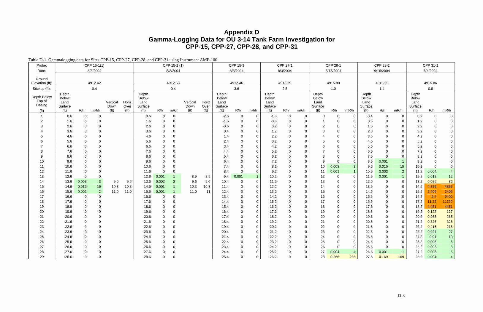
D-3
Appendix D Gamma-Logging Data for OU 3-14 Tank Farm Investigation for
CPP-15, CPP-27, CPP-28, and CPP-31
Table D-1. Gammalogging data for Sites CPP-15, CPP-27, CPP-28, and CPP-31 using Instrument AMP-100. Probe: CPP 15-1(1) CPP 15-2 (1) CPP 15-3 CPP 27-1 CPP 28-1 CPP 28-2 CPP 31-1 Date: 8/3/2004 8/3/2004 8/3/2004 8/3/2004 8/18/2004 9/16/2004 8/4/2004
Ground Elevation (ft): 4912.42 4912.63 4912.46 4913.29 4915.80 4915.95 4915.86 Stickup (ft): 0.4 0.4 3.6 2.8 1.0 1.4 0.8
Depth Below Top of Casing
(ft)
Depth Below Land
Surface (ft) R/h mR/h
Vertical Down
(ft)
Horiz Over (ft)
Depth Below Land
Surface (ft) R/h mR/h
Vertical Down
(ft)
Horiz Over (ft)
Depth Below Land
Surface (ft) R/h mR/h
Depth Below Land
Surface (ft) R/h mR/h
Depth Below Land
Surface (ft) R/h mR/h
Depth Below Land
Surface (ft) R/h mR/h
Depth Below Land
Surface (ft) R/h mR/h
1 0.6 0 0 0.6 0 0 -2.6 0 0 -1.8 0 0 0 0 0 -0.4 0 0 0.2 0 0 2 1.6 0 0 1.6 0 0 -1.6 0 0 -0.8 0 0 1 0 0 0.6 0 0 1.2 0 0 3 2.6 0 0 2.6 0 0 -0.6 0 0 0.2 0 0 2 0 0 1.6 0 0 2.2 0 0 4 3.6 0 0 3.6 0 0 0.4 0 0 1.2 0 0 3 0 0 2.6 0 0 3.2 0 0 5 4.6 0 0 4.6 0 0 1.4 0 0 2.2 0 0 4 0 0 3.6 0 0 4.2 0 0 6 5.6 0 0 5.6 0 0 2.4 0 0 3.2 0 0 5 0 0 4.6 0 0 5.2 0 0 7 6.6 0 0 6.6 0 0 3.4 0 0 4.2 0 0 6 0 0 5.6 0 0 6.2 0 0 8 7.6 0 0 7.6 0 0 4.4 0 0 5.2 0 0 7 0 0 6.6 0 0 7.2 0 0 9 8.6 0 0 8.6 0 0 5.4 0 0 6.2 0 0 8 0 0 7.6 0 0 8.2 0 0 10 9.6 0 0 9.6 0 0 6.4 0 0 7.2 0 0 9 0 0 8.6 0.001 1 9.2 0 0 11 10.6 0 0 10.6 0 0 7.4 0 0 8.2 0 0 10 0.003 3 9.6 0.015 15 10.2 0 0 12 11.6 0 0 11.6 0 0 8.4 0 0 9.2 0 0 11 0.001 1 10.6 0.002 2 11.2 0.004 4 13 12.6 0 0 12.6 0.001 1 8.9 8.9 9.4 0.001 1 10.2 0 0 12 0 0 11.6 0.001 1 12.2 0.012 12 14 13.6 0.003 3 9.6 9.6 13.6 0.002 2 9.6 9.6 10.4 0 0 11.2 0 0 13 0 0 12.6 0 0 13.2 0.086 86 15 14.6 0.016 16 10.3 10.3 14.6 0.001 1 10.3 10.3 11.4 0 0 12.2 0 0 14 0 0 13.6 0 0 14.2 4.856 4856 16 15.6 0.002 2 11.0 11.0 15.6 0.001 1 11.0 11 12.4 0 0 13.2 0 0 15 0 0 14.6 0 0 15.2 2.406 2406 17 16.6 0 0 16.6 0 0 13.4 0 0 14.2 0 0 16 0 0 15.6 0 0 16.2 9.4 9400 18 17.6 0 0 17.6 0 0 14.4 0 0 15.2 0 0 17 0 0 16.6 0 0 17.2 11.22 11220 19 18.6 0 0 18.6 0 0 15.4 0 0 16.2 0 0 18 0 0 17.6 0 0 18.2 4.451 4451 20 19.6 0 0 19.6 0 0 16.4 0 0 17.2 0 0 19 0 0 18.6 0 0 19.2 0.127 127 21 20.6 0 0 20.6 0 0 17.4 0 0 18.2 0 0 20 0 0 19.6 0 0 20.2 0.265 265 22 21.6 0 0 21.6 0 0 18.4 0 0 19.2 0 0 21 0 0 20.6 0 0 21.2 0.326 326 23 22.6 0 0 22.6 0 0 19.4 0 0 20.2 0 0 22 0 0 21.6 0 0 22.2 0.215 215 24 23.6 0 0 23.6 0 0 20.4 0 0 21.2 0 0 23 0 0 22.6 0 0 23.2 0.027 27 25 24.6 0 0 24.6 0 0 21.4 0 0 22.2 0 0 24 0 0 23.6 0 0 24.2 0.01 10 26 25.6 0 0 25.6 0 0 22.4 0 0 23.2 0 0 25 0 0 24.6 0 0 25.2 0.005 5 27 26.6 0 0 26.6 0 0 23.4 0 0 24.2 0 0 26 0 0 25.6 0 0 26.2 0.003 3 28 27.6 0 0 27.6 0 0 24.4 0 0 25.2 0 0 27 0.004 4 26.6 0.001 1 27.2 0.005 5 29 28.6 0 0 28.6 0 0 25.4 0 0 26.2 0 0 28 0.266 266 27.6 0.169 169 28.2 0.004 4

Table D-1. (continued).
D-4
Probe: CPP 15-1(1) CPP 15-2 (1) CPP 15-3 CPP 27-1 CPP 28-1 CPP 28-2 CPP 31-1 Date: 8/3/2004 8/3/2004 8/3/2004 8/3/2004 8/18/2004 9/16/2004 8/4/2004
Ground Elevation (ft): 4912.42 4912.63 4912.46 4913.29 4915.80 4915.95 4915.86 Stickup (ft): 0.4 0.4 3.6 2.8 1.0 1.4 0.8
Depth Below Top of Casing
(ft)
Depth Below Land
Surface (ft) R/h mR/h
Vertical Down
(ft)
Horiz Over (ft)
Depth Below Land
Surface (ft) R/h mR/h
Vertical Down
(ft)
Horiz Over (ft)
Depth Below Land
Surface (ft) R/h mR/h
Depth Below Land
Surface (ft) R/h mR/h
Depth Below Land
Surface (ft) R/h mR/h
Depth Below Land
Surface (ft) R/h mR/h
Depth Below Land
Surface (ft) R/h mR/h
30 26.4 0 0 27.2 0 0 29 2.867 2867 28.6 2.73 2730 29.2 0.005 5 31 27.4 0 0 28.2 0 0 30 0.320 320 29.6 1.74 1740 30.2 0.004 4 32 28.4 0 0 29.2 0 0 31 0.006 6 30.6 0.025 25 31.2 0.003 3 33 29.4 0 0 30.2 0 0 32 0.006 6 31.6 0.007 7 32.2 0.002 2 34 30.4 0 0 31.2 0 0 33 0.006 6 32.6 0.001 1 33.2 0.002 2 35 1-49 mR/hr 31.4 0 0 32.2 0 0 34 0.003 3 33.6 0 0 34.2 0.002 2 36 50-999 mR/hr 32.4 0 0 33.2 0 0 35 0.002 2 34.6 0 0 35.2 0.002 2 37 1000-1999 mR/hr 33.4 0 0 34.2 0 0 36 0 0 35.6 0 0 36.2 0.002 2 38 2000 or greater mR/hr 34.4 0 0 35.2 0 0 37 0 0 36.6 0 0 37.2 0.001 1 39 (1) Angle probe hole 35.4 0 0 36.2 0 0 38 0 0 37.6 0 0 38.2 0.003 3 40 36.4 0 0 37.2 0 0 39 0 0 38.6 0 0 39.2 0.004 4 41 37.4 0 0 38.2 0 0 40 0 0 39.6 0 0 42 38.4 0 0 39.2 0 0 41 0 0 40.6 0 0 43 39.4 0 0 40.2 0 0 42 0 0 41.6 0 0 44 40.4 0 0 41.2 0 0 43 0 0 42.6 0 0 45 41.4 0 0 42.2 0 0 44 0 0 43.6 0 0 46 42.4 0 0 45 0 0 44.6 0 0
47 43.4 0 0 46 0 0 45.6 0 0 48 45.4 0 0 48 0 0 47.6 0 0 49 47.4 0 0 50 0 0 49.6 0 0 50 48.4 0 0 51 0 0 50.6 0 0 51 51.6 0 0 52 52.6 0 0 53 53.6 0 0 54 54.6 0 0