end user approach to chromeed editor - …crow/callofjaurez/chromeeditor/chromed...end user approach...
TRANSCRIPT

End user approach to ChromeEd Editor
Author: Marek PszczolkowskiDocument version: 12Date: 30.6.2006Concerns: „ChromeEd” version attached to Call of JuarezTranslation of document version 8.0: Tomasz Gajer

„ChromEd” documentation – ver. 12.0
1 Table of contents
1 TABLE OF CONTENTS ..................................................................................................................................... 2
2 CHROMEED FEATURES .................................................................................................................................. 5
2.1 ELEMENTS OF THE GAME LEVEL THAT CANNOT BE CREATED BY CHROMEED .................................................................. 5 2.2 ELEMENTS OF THE GAME LEVEL SUPPORTED BY CHROMEED ....................................................................................... 5
3 CHROMEED FILES ........................................................................................................................................... 6
3.1 FILES THAT ARE REQUIRED TO RUN CHROMEED ........................................................................................................ 6 3.2 FILES USED BY CHROMEED .................................................................................................................................. 8
3.2.1 Bitmaps: .................................................................................................................................................. 8 3.2.2 3D objects ............................................................................................................................................... 8 3.2.3 Sounds .................................................................................................................................................... 8 3.2.4 Other ....................................................................................................................................................... 8
3.3 RESULT FILES – CREATED BY CHROMEED ................................................................................................................ 8 3.4 „GAME.INI”, „EDITORSTART.INI” AND “EDITORSTARTGAME.INI” FILES ..................................................................... 9
3.4.1 „Game.ini” ............................................................................................................................................. 9 3.4.2 „EditorStart.ini” .................................................................................................................................... 9
3.4.2.1 Most often used Java classes section ............................................................................ 10 3.4.2.2 Class section from the Object Selection window .......................................................... 10 3.4.2.3 Predefined Meshes section ............................................................................................ 10 3.4.2.4 Editor helper section ...................................................................................................... 11 3.4.2.5 Gizmo materials section ................................................................................................ 12 3.4.2.6 Protected map section ................................................................................................... 12 3.4.2.7 Common classes section ............................................................................................... 12 3.4.2.8 Hide as helpers section .................................................................................................. 13 3.4.2.9 Game section ................................................................................................................. 13
3.5 MESH DEFINITION FILES AND THEIR CONSTRUCTION ................................................................................................. 13 3.5.1 „def” file construction : ....................................................................................................................... 13
3.6 SKIN DEFINITION FILES AND THEIR CONSTRUCTION ................................................................................................... 15
4 CHROMEED BASICS ...................................................................................................................................... 16
4.1 THE STARTUP WINDOW ....................................................................................................................................... 16 4.2 THE WIZARD ................................................................................................................................................... 17 4.3 CHROMEED SCREEN LAYOUT ............................................................................................................................... 18
4.3.1 Viewports .............................................................................................................................................. 18 4.3.2 The editor status bar ............................................................................................................................. 18
4.4 EDITOR FUNCTIONALITIES ................................................................................................................................... 18 4.4.1 Editor menu .......................................................................................................................................... 19 4.4.2 Editor toolbar ....................................................................................................................................... 20 4.4.3 Refresh toolbar ..................................................................................................................................... 20 4.4.4 Object selection .................................................................................................................................... 21
4.4.4.1 Object selection – creation and use ............................................................................... 21 4.4.4.2 Filtering and object selection class creation ................................................................ 23
4.4.5 Class selection ...................................................................................................................................... 24 4.4.6 Object layers ......................................................................................................................................... 24 4.4.7 Setting the object attributes .................................................................................................................. 25
4.4.7.1 ‘Anims’ tab .................................................................................................................... 29 4.4.7.2 ‘Comment’ tab ............................................................................................................... 31 4.4.7.3 ‘Dyn. Lights’ tab ........................................................................................................... 31 4.4.7.4 ‘Info’ tab ........................................................................................................................ 34 4.4.7.5 ‘Fields’ tab ..................................................................................................................... 36
4.4.7.5.1 Browse mesh .............................................................................................. 46 4.4.7.6 ‘Light’ tab ...................................................................................................................... 46
2

„ChromEd” documentation – ver. 12.0
4.4.7.7 ‘Lighting’ tab ................................................................................................................. 47 4.4.7.7.1 Object layout .............................................................................................. 48 4.4.7.7.2 Level layout ................................................................................................ 51
4.4.7.8 ‘Matrix’ tab .................................................................................................................... 52 4.4.7.9 ‘Mimics’ tab .................................................................................................................. 52 4.4.7.10 ‘Misc’ tab – object layout ............................................................................................ 54 4.4.7.11 ‘Object’ tab .................................................................................................................. 56 4.4.7.12 ‘Skins’ tab .................................................................................................................... 57 4.4.7.13 ‘Comment’ tab ............................................................................................................. 58 .................................................................................................................................................. 58 4.4.7.14 ‘Fog’ tab ...................................................................................................................... 59 4.4.7.15 ‘Sky’ tab ...................................................................................................................... 60 4.4.7.16 ‘Terrain’ tab ................................................................................................................. 61 4.4.7.17 ‘Trees’ tab .................................................................................................................... 62 4.4.7.18 ‘Varlist’ tab .................................................................................................................. 62 4.4.7.19 ‘Water’ tab ................................................................................................................... 67
4.4.8 Object hiding ........................................................................................................................................ 68 4.4.9 Object groups ....................................................................................................................................... 68 4.4.10 Object selections ................................................................................................................................. 70 4.4.11 Reference window ............................................................................................................................... 71
4.4.11.1 Object references ......................................................................................................... 71 4.4.11.2 String attributes ........................................................................................................... 72
4.4.12 Object clipboard ................................................................................................................................. 72 4.4.13 Object Collapser ................................................................................................................................. 73
4.4.13.1 The Idea ....................................................................................................................... 73 4.4.13.2 User interface .............................................................................................................. 74
4.4.14 Running the game in editor ................................................................................................................ 75 4.4.15 Object selection groups management window (from the file) ............................................................ 76
4.4.15.1 *.trk format file structure ............................................................................................ 76 4.4.16 Object selection filtering .................................................................................................................... 76 4.4.17 Process window .................................................................................................................................. 77 4.4.18 Screenshot window ............................................................................................................................. 83 4.4.19 Collapsing with cell division .............................................................................................................. 84 4.4.20 Job list ................................................................................................................................................ 84 4.4.21 Occluders ............................................................................................................................................ 86 4.4.22 Map compilation ................................................................................................................................. 87
5 EDITOR OPTIONS ........................................................................................................................................... 88
5.1 RENDERING OPTIONS .......................................................................................................................................... 88 5.2 MISCELLANEOUS OPTIONS ................................................................................................................................... 90
5.2.1 ‘Misc’ tab ............................................................................................................................................. 90 5.2.2 ‘Actions’ tab ......................................................................................................................................... 91
5.3 ERROR WINDOW ................................................................................................................................................ 91 5.4 KEY SHORTCUTS FOR 3D VIEW ............................................................................................................................ 92
6 EXISTING PLUG - INS ...................................................................................................................................... 93
6.1 ENVIRONMENT .................................................................................................................................................. 93 6.1.1 Purpose ................................................................................................................................................. 93 6.1.2 Dependence on other plug-ins .............................................................................................................. 93 6.1.3 User interface ....................................................................................................................................... 93
6.1.3.1 AI collision map creation .............................................................................................. 93 6.1.3.2 Saving the heightmap/normals map .............................................................................. 96 6.1.3.3 ‘Renumerate objects’ .................................................................................................... 96
6.2 FORESTER ........................................................................................................................................................ 97 6.2.1 Plug-in idea and purpose ..................................................................................................................... 97
3

„ChromEd” documentation – ver. 12.0
6.2.1.1 Trees .............................................................................................................................. 97 6.2.1.2 Grass ............................................................................................................................. 97
6.2.2 Description ........................................................................................................................................... 97 6.2.2.1 Plug-in menu ................................................................................................................. 97 6.2.2.2 Plug-in toolbar ............................................................................................................... 98 6.2.2.3 Plug-in form .................................................................................................................. 98 6.2.2.4 Tree lighting calculation window ................................................................................ 103 6.2.2.5 Single tree edition ....................................................................................................... 103
6.3 LIGHTMAPSED ................................................................................................................................................ 104 6.3.1 Purpose ............................................................................................................................................... 104 6.3.2 Dependence on other plug-ins ............................................................................................................ 104 6.3.3 User interface ..................................................................................................................................... 104 6.3.4 LightmapsEd form .............................................................................................................................. 104
6.3.4.1 Terrain lightmap generation ........................................................................................ 106 6.3.4.2 Override parameters .................................................................................................... 106 6.3.4.3 Generation process for objects .................................................................................... 106 6.3.4.4 Setting the light source properties ............................................................................... 107 6.3.4.5 Distributed generation of lightmaps for objects .......................................................... 107
6.4 MESH BROWSER ............................................................................................................................................. 107 6.4.1 Purpose ............................................................................................................................................... 107 6.4.2 Dependence on other plug-ins ............................................................................................................ 107 6.4.3 Transformations in viewport .............................................................................................................. 108
6.4.3.1 Views ........................................................................................................................... 108 6.4.3.2 Observer (camera) positioning .................................................................................... 108 6.4.3.3 Object interaction ........................................................................................................ 109
6.4.4 Plug-in menu ....................................................................................................................................... 110 6.4.5 Plug-in toolbar and actions executed from the toolbar ...................................................................... 111
6.4.5.1 Main toolbar ................................................................................................................ 111 6.4.5.2 Scene toolbar ............................................................................................................... 112 6.4.5.3 Align toolbar ................................................................................................................ 112
6.4.6 Plug-in main widow description ......................................................................................................... 114 6.5 FILMS ............................................................................................................................................................ 117
6.5.1 Purpose ............................................................................................................................................... 117 6.5.2 Importing and exporting movies ......................................................................................................... 121 6.5.3 Dependence on other plug-ins ............................................................................................................ 122 6.5.4 User interface ..................................................................................................................................... 122
6.5.4.1 Plug-in menu ............................................................................................................... 122 6.5.4.2 Plug-in toolbar ............................................................................................................. 122 6.5.4.3 Plug-in main window: ................................................................................................. 123 6.5.4.4 Scenario window ......................................................................................................... 125
6.5.4.4.1 Toolbar ..................................................................................................... 125 6.5.4.4.2 Time scale ................................................................................................ 126 6.5.4.4.3 Information section .................................................................................. 126 6.5.4.4.4 Tracks ....................................................................................................... 126 6.5.4.4.5 Settings window ....................................................................................... 128 6.5.4.4.6 Filter track window .................................................................................. 129 6.5.4.4.7 Key filter and settings window ................................................................ 129 6.5.4.4.8 Camera parameters window ..................................................................... 130 6.5.4.4.9 ‘Subtrack’ parameters window ................................................................. 130 6.5.4.4.10 Adjust time window ............................................................................... 131 6.5.4.4.11 Key attributes window ........................................................................... 131
6.5.4.5 Camera selection ......................................................................................................... 132 6.5.4.6 Point keys multiselection ............................................................................................ 132
4

„ChromEd” documentation – ver. 12.0
6.6 TERRAINED .................................................................................................................................................... 133 6.6.1 Purpose ............................................................................................................................................... 133
6.6.1.1 Common setting for all tools ....................................................................................... 133 6.6.1.2 Tool description ........................................................................................................... 133 6.6.1.3 ‘Blur’ tool .................................................................................................................... 134 6.6.1.4 ‘Point height’ tool ........................................................................................................ 134 6.6.1.5 ‘Posterize’ tool ............................................................................................................ 135 6.6.1.6 ‘Relative height’ tool ................................................................................................... 135 6.6.1.7 ‘Set height’ tool ........................................................................................................... 135 6.6.1.8 ‘Ramp’ tool .................................................................................................................. 135 6.6.1.9 Tool predefining .......................................................................................................... 136
6.6.2 Dependence on other plug-ins ............................................................................................................ 137 6.6.3 User interface ..................................................................................................................................... 138
6.6.3.1 Plug-in main form ....................................................................................................... 138 6.6.3.2 Bitmap edition window ............................................................................................... 139 7 PHYSICS ........................................................................................................................................................... 141
7.1 PURPOSE ........................................................................................................................................................ 141 7.1.1 Attuning and testing object parameters connected with physics ........................................................ 141 7.1.2 Laying out objects with use of physics ............................................................................................... 141
7.2 USER INTERFACE ............................................................................................................................................ 141
8 THE RULES OF PREPARING JAVA ATTRIBUTES TO BE EDITED WITH USE OF CHROMED ... 142
8.1 FORMAT OF A STRING DESCRIBING ATTRIBUTES IN A CUSTOM RTTI SYSTEM .............................................................. 142 8.1.1 Flags (F) ............................................................................................................................................. 142 8.1.2 Edit flags (E) ...................................................................................................................................... 143 8.1.3 Category (C) ....................................................................................................................................... 144 8.1.4 Description (D) ................................................................................................................................... 144 8.1.5 Minimum (M), maximum (X) and step (S) .......................................................................................... 144 8.1.6 Additional data (A) ............................................................................................................................. 144 8.1.7 Package (P) ........................................................................................................................................ 144 8.1.8 Precision (R) ....................................................................................................................................... 145
9 DICTIONARY .................................................................................................................................................. 145
10 SUMMARY ..................................................................................................................................................... 145
1 ChromeEd featuresChromeEd is an editor that enables you to create maps for games based on the Chrome
game engine. It enables you to create a complete game level along with the interaction with all level objects.
1.1 Elements of the game level that cannot be created by ChromeEd• bitmaps/textures (you may only edit the existing map aligned to the terrain the same way as the
color map)• 3D objects (Mesh)• soundsTo create these files you need to use other tools.
1.1 Elements of the game level supported by ChromeEd• terrain generation based on the previously prepared bitmaps and its later edition• determination of the basic parameters of the game level (e.g. sun, terrain size etc. – it will be
described more in detail in paragraph 6.1)• placement and transformation of 3D objects• linking objects with classes in Java and setting their attributes
5

„ChromEd” documentation – ver. 12.0
• lightmap creation• films and directed cut-scenes creation (see 6.5)• vegetation generation (trees and grass)• creation of objects relations (it concerns both object hierarchy and interiors – described further in
this document)• edition of color map or any other map aligned to the terrain
1 ChromeEd files
To function properly the ChromeEd editor requires specified files and their proper location in the directory tree. The basic principle is that all file paths are stored relatively to the ChromeEd work folder.
1.1 Files that are required to run ChromeEdThey all have to be located in an editor work folder. All subfolders are given relatively to this folder
a) ChromEd.exe – application executable
b) DLL libraries:• A3dapi.dll• ChromeEngine3.dll• FileSystem.dll• ImageLib.dll• JavaDebug.dll• Memdump.dll• Mfc71.dll• Msvcp71.dll• Msvcr71.dll• Ogg.dll• VorbisEnc.dll• VorbisFile.dll• Vorbis.dll
c) ini files• Game.ini – defines the path to java classes needed for engine initialization• EditorStart.ini, EditorStartGame.ini – configuration files containing the basic definitions (e.g.
editor helpers definition (see the dictionary), predefined meshes etc.)
d) ChromeEdOptions.scr – this file is not required. It stores editor settings and it is loaded at the editor startup. All user changes made to editor settings will be stored to that file.
e) EditorRenderOptions.scr - this file is not required, although it will be automatically created – editor render settings are stored in it
f) DefaultKeysParams.fkd – contains default settings of Films plug-in keys
g) DefaultShortcuts.sdat – contains default keyboard settings
h) PredefinedBrushes.ini – contains predefined tools for terrain modification by TerrainEd plug-ini) R_init.scr – file with some of the basic settings concerning renderer (e.g. paths for textures and
material search)j) Subfolder „ .\Data\Interface ”, containing:
• NoMesh.msh – default Mesh for those objects that Meshes were not fund• Editor Helper Meshes (providing that the paths in EditorStart.ini file were not changed)• Default.wav – default sound
k) Subfolders with java classes for the current game with the engine Java classes – those paths need to be located in Game.ini
6

„ChromEd” documentation – ver. 12.0
l) Subfolder „ .\jre ” with Java environmentm) Subfolder „ .\Plugins ” with plug-in dlls
7

„ChromEd” documentation – ver. 12.0
1.1 Files used by ChromeEdDuring work with ChromeEd the following file formats will be used:
1.1.1 Bitmaps:• jpg• png• tga• dds
1.1.2 3D objects• 3da• msh
1.1.3 Sounds• wav• ogg
1.1.1 Other• cem – exported movies (Films plug-in)• def – Mesh definition file• edcs – class selection file (described further in this document)• eds – object selection file (described further in this document )• fkd – key data file (Films plug-in)• fscr – exported vegetation file (Forester plug-in)• height – terrain heightmap• ini – Mesh (a .3da file object) animation sequences file• jl – job list file• lmap – object lightmaps• lmf – Mesh lighting model file• map – game level map• sdat – keyboard settings• skn – object skin definition file• track – file with position tracks or rotation (Films plug-in)
1.1 Result files – created by ChromeEd• bak, ba1, ba2, ba3 – map back-ups (auto-created)• cem – exported movies• edcs – exported class selections• eds – exported selections• exp – compiled map file• fscr – exported vegetation• fxm – heightmap for fx’s• ini – stored animation sequences• jl – job list file• lmf – Mesh lighting models• lmp – object lightmaps• map – game level maps• pfm – AI collision maps• s3d – static geometry (created in map compilation process)• sdat – keyboard settings• stl – terrain or geometry exported to stl format
8

„ChromEd” documentation – ver. 12.0
• track – file with position tracks or rotation (described in Films plug-in)
1.2 „Game.ini”, „EditorStart.ini” and “EditorStartGame.ini” filesGeneral rules of ini files (and any other script files) construction (doesn’t concern files with object animation sequences):
• they have heading and data lines• each heading line starts with ‘!’ sign and defines in brackets the quantity and type of given key
attributes• each data line consist one key defined in heading• after the last data line there needs to be a EOL (End Of Line) mark• all lines with // prefix are treated as comment line
The file construction will be described with use of existing files:
1.2.1 „Game.ini”
// path where game will find compiled classes!JavaClasses(s)
// name of packed classes jar file!JavaClassesPacked(s)
// class inherited from Game spawned first and running all game!JavaGameClassName(s)
// source path of classes for java debugger!JavaClassSourcePath(s)
// name of game's locale!Locale(s)
JavaGameClassName("LawmanGame")JavaClasses("Java")JavaClassesPacked("code")JavaClassSourcePath("JavaEngine/")JavaClassSourcePath("JavaLawman/")Locale("En")
Comments:• ten first lines make the heading with comments to each key – they need to be left unchanged• the eleventh line defines the name of the Java game class – it has to be only one• all the other key lines are not significant from the Editor point of view
1.2.2 „EditorStart.ini”In this file you can see following sections:• most often used Java classes section• class list section that will appear in the selection window (see 4.4.2)• predefined meshes section• editor helpers section• gizmo materials section• protected maps section• common classes section• hide as helpers section• game section
9

„ChromEd” documentation – ver. 12.0
1.2.2.1 Most often used Java classes section
// Preset() - section to place most often used classes!Preset()// PresetSingle( s ) - class names in section Preset!PresetSingle( s )
Preset(){
PresetSingle( "TriggerObject" )PresetSingle( "PlayerSingle" )PresetSingle( "NewAIHuman" )
}
Comments:In this sections there are located all Java classes that will ALWAYS be displayed in Object Attributes window (subsection: the most often used list) upon the Java class selection (see 4.4.4 – Object Class Change window)Each key PresetSingle adds one class to the list. There should be only one Preset key – it groups the PresetSingle keys.
1.2.2.2 Class section from the Object Selection window//EdClassSelections() - section to store content of EdClassSelections.ini file!EdClassSelections()//ClassSelection( class selection name to be displayed in combobox)!ClassSelection( s )//Class( class name, include inherited classes: 1 - yes, other - no )!Class( s , n )
EdClassSelections(){ClassSelection("SoundEmitters"){
Class("SoundEmitter", 1)}
ClassSelection("AI"){
Class("AIGroup", 1)Class("NewAI", 1)Class("Waypoint",0)
}}
Comments:• This example consists of only one section of the „EditorStart.ini” file given with the game because
of its size• The EdClassSelections groups ClassSelection keys only and should be only one of that kind• Each ClassSelection key makes one position in Object Selection window combobox (see 4.4.2).• Each key defines class pack that are to be concerned upon its selection in combobox. There may
be many keys of this kind.• To each ClassSelection key there may be attached many Class keys. Each of them defines the
class that belongs to that pack. If the second attribute of the key is ‘1’ then all the classes inheriting from the first attribute of that key also belong to that pack. In other case only the given class belongs to the pack.
1.2.2.3 Predefined Meshes section
// EditorMeshes() - section to store content of EditorMeshes.ini file
10
„ChromEd” documentation – ver. 12.0
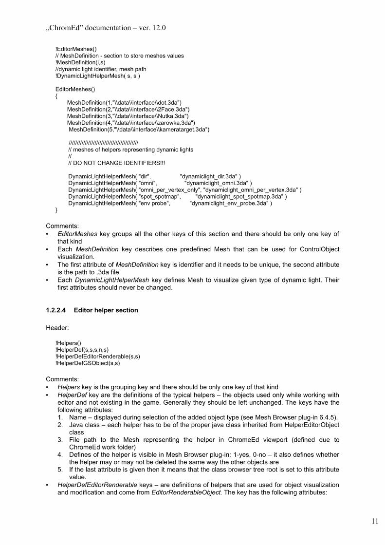
!EditorMeshes()// MeshDefinition - section to store meshes values!MeshDefinition(i,s)//dynamic light identifier, mesh path!DynamicLightHelperMesh( s, s )
EditorMeshes(){
MeshDefinition(1,"\\data\\interface\\dot.3da")MeshDefinition(2,"\\data\\interface\\2Face.3da")MeshDefinition(3,"\\data\\interface\\Nutka.3da")MeshDefinition(4,"\\data\\interface\\zarowka.3da")MeshDefinition(5,"\\data\\interface\\kameratarget.3da")
/////////////////////////////////////////// // meshes of helpers representing dynamic lights // // DO NOT CHANGE IDENTIFIERS!!!
DynamicLightHelperMesh( "dir", "dynamiclight_dir.3da" ) DynamicLightHelperMesh( "omni", "dynamiclight_omni.3da" ) DynamicLightHelperMesh( "omni_per_vertex_only", "dynamiclight_omni_per_vertex.3da" ) DynamicLightHelperMesh( "spot_spotmap", "dynamiclight_spot_spotmap.3da" ) DynamicLightHelperMesh( "env probe", "dynamiclight_env_probe.3da" )}
Comments:• EditorMeshes key groups all the other keys of this section and there should be only one key of
that kind• Each MeshDefinition key describes one predefined Mesh that can be used for ControlObject
visualization.• The first attribute of MeshDefinition key is identifier and it needs to be unique, the second attribute
is the path to .3da file.• Each DynamicLightHelperMesh key defines Mesh to visualize given type of dynamic light. Their
first attributes should never be changed.
1.2.2.4 Editor helper section
Header:
!Helpers()!HelperDef(s,s,s,n,s)!HelperDefEditorRenderable(s,s)!HelperDefGSObject(s,s)
Comments:• Helpers key is the grouping key and there should be only one key of that kind• HelperDef key are the definitions of the typical helpers – the objects used only while working with
editor and not existing in the game. Generally they should be left unchanged. The keys have the following attributes:1. Name – displayed during selection of the added object type (see Mesh Browser plug-in 6.4.5).2. Java class – each helper has to be of the proper java class inherited from HelperEditorObject
class3. File path to the Mesh representing the helper in ChromeEd viewport (defined due to
ChromeEd work folder)4. Defines of the helper is visible in Mesh Browser plug-in: 1-yes, 0-no – it also defines whether
the helper may or may not be deleted the same way the other objects are5. If the last attribute is given then it means that the class browser tree root is set to this attribute
value.• HelperDefEditorRenderable keys – are definitions of helpers that are used for object visualization
and modification and come from EditorRenderableObject. The key has the following attributes:
11

„ChromEd” documentation – ver. 12.0
1. Name – see HelperDef description2. Java abstract base class – the class browser treats the given class as the tree root – it must
be specified• HelperDefGSObject keys are the definitions of helpers that are used for operations on objects
inheriting from GameObject but not from MeshObject or EditorRenderableObject. The attributes are the same as HelperDefEditorRenderable keys
Example (from EditorStart.ini file):
Helpers(){HelperDef("Light","LightEditorObject","data\\interface\\zarowka.3da",1,"")HelperDefEditorRenderable("Dynamic light", "LightObject")HelperDefGSObject("Movie","Movie")}
1.2.2.5 Gizmo materials section
// materials used by gizmo
!GizmoMaterials()!GizmoMaterial( s )!GizmoHighLightMaterial( s )!GizmoScaleMaterial( s )!GizmoScaleHighLightMaterial( s )
GizmoMaterials(){GizmoMaterial( "Gizmo II SI.mat" )GizmoHighLightMaterial( "Gizmo SI.mat" )GizmoScaleMaterial( "GizmoScale.mat" )GizmoScaleHighLightMaterial( "GizmoScaleSelected.mat" )}
This section should be left unchanged.
1.2.2.6 Protected map section
Example taken from XpandRally game:
!ProtectedMapWarning( s )!ProtectedMap( s )
ProtectedMap( "data/maps/nevada/nevada.map" )
Comments:• ProtectedMapWarning key enables you to define the comment that will be displayed while trying to
overwrite any of the maps from this section• ProtectedMap key enables you to specify the maps you want to protect
1.2.2.7 Common classes section
Example taken from XpandRally game:
!CommonClasses()!CommonClass( s, s ) //name, description
CommonClasses()
12
„ChromEd” documentation – ver. 12.0
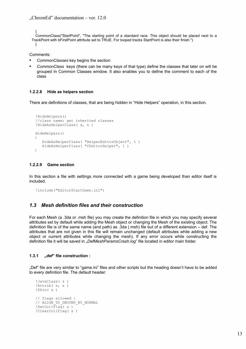
{CommonClass("StartPoint", "The starting point of a standard race. This object should be placed next to a
TrackPoint with bFirstPoint attribute set to TRUE. For looped tracks StartPoint is also their finish.")}
Comments:• CommonClasses key begins the section• CommonClass keys (there can be many keys of that type) define the classes that later on will be
grouped In Common Classes window. It also enables you to define the comment to each of the class
1.2.2.8 Hide as helpers section
There are definitions of classes, that are being hidden in “Hide Helpers” operation, in this section.
!HideHelpers()//class name; get inherited classes !HideAsHelperClass( s, n )
HideHelpers(){ HideAsHelperClass( "HelperEditorObject", 1 ) HideAsHelperClass( "CEditorHelper", 1 )}
1.2.2.9 Game section
In this section a file with settings more connected with a game being developed than editor itself is included.
!include("EditorStartGame.ini")
1.3 Mesh definition files and their construction
For each Mesh (a .3da or .msh file) you may create the definition file in which you may specify several attributes set by default while adding the Mesh object or changing the Mesh of the existing object. The definition file is of the same name (and path) as .3da (.msh) file but of a different extension – def. The attributes that are not given in this file will remain unchanged (default attributes while adding a new object or current attributes while changing the mesh). If any error occurs while constructing the definition file it will be saved in „DefMeshParamsCrash.log” file located in editor main folder.
1.3.1 „def” file construction :
„Def” file are very similar to “game.ini” files and other scripts but the heading doesn’t have to be added to every definition file. The default header:
!JavaClass( s )!Attrib( s, s )!Skin( s )
// flags allowed :// ALIGN_TO_GROUND_BY_NORMAL!SetCollFlag( s )!ClearCollFlag( s )
13

„ChromEd” documentation – ver. 12.0
// flags allowed :// COLLISIONS// BLOCK_MOVE// BLOCK_TRACE// FX_PARTICLE_COLLISIONS// NO_ANIMATION// STOP_BY_PATHFINDER// NOT_STATIC// PATHFINDER_VISIBLE// NO_CULL_BY_SIZE// RECEIVE_SHADOWS// NOT_STOPS_RAIN// TERRAIN_OBJECT// ENV_MAP_OBJECT// CAST_SHADOWS!SetFlag( s )!ClearFlag( s )
// flags allowed:// FACING_TOWARDS_OBSERVER// NO_WATER_RANGE_CULL// MESH_OCCLUDER!SetMeshFlag( s )!ClearMeshFlag( s )
// types allowed:// ELLIPSOID// PERFACE// PERFACEOBJECT!CollType( s )
// types allowed :// COARSE_BOX// COARSE_ELLIPSOID// ELEMENT_BOX// ELEMENT_ELLIPSOID// PERFACE// extents!CollTraceType( s )
!CastShadows( n )!UseDefaultLightmapParams( n )!GenerateLightmaps( n )!SamplesPerPixel( n )!Texels( f )!UseDefaultAmbient()!UseVarlistAmbient( n )!Ambient( n, n, n )!RGBFlag( n )!AlphaFlag( n )!AmbientOcclusionSamples( n )!AmbientOcclusionRayLength( f )!AmbientOcclusionRaytraceBothDirs( n )!SmoothLightmaps( n )!UseAllLights( n )!MeshColor( n, n, n )
Comments:• JavaClass key – java class that is automatically set to the object. Additionally it is the grouping key
of the keys described below. Each of the key concerns the attributes set in its name. In every case the first parameter is the attribute name and the second is value.• Attrib
• SetCollFlag and ClearCollFlag, SetFlag and ClearFlag, SetMeshFlag and ClearMeshFlag keys enable you to set/clear the proper object flags (the flag names are specified in comments)
14

„ChromEd” documentation – ver. 12.0
• CollType, CollAction, CollHandler, CollTraceType keys– enable to set the parameters of collisions and tracking (the values allowed are given in comments – they are equal to values that may be set to this attributes In editor)
• CastShadows key– specifies if the object is to cast shadows or not• GenerateLightmaps key– it specifies that the given object will have the lightmaps generated.
Additionally it is the grouping key for the following keys:• SamplesPerPixel – specifies the number of samples calculated per each pixel of the lightmap
(see 6.3)• Texels – specifies the number of texels per meter for the lightmap• UseDefaultAmbient – turns the default ambient on while generating the object lightmap• UseVarlistAmbient – specifies if ambient set in a varlist is to be used in ligthmap generation
(instead of ambient set for this object)• Ambient – allows to set the ambient used while generating the object lightmap. The color
parameters are given from [0, 255] range• RGBFlag – flags used to determine which parts of ligthmap generation process are supposed
to write their results in lightmap RGB channels• AlphaFlag – same as RGBFlag but concerns alpha channel• AmbientOcclusionSamples – number of samples per texel (in ambient occlusion calculations)• AmbientOcclusionRayLength – length of all rays casted in ambient occlusion calculations• AmbientOcclusionRaytraceBothDirs – specifies whether all rays are to be traced in both
directions (in ambient occlusion calculations)• UseAllLights – specifies whether all lightmap lights are to be traced while generating the
object lightmap• MeshColor key – defines the Mesh color that can be used later on in materials
1.4 Skin definition files and their construction
Skin definition files .skn that can be attached to objects must be located in the same folder the respective .3da files are located. Such file is built the same way the standard script file is built and it has the following default header (it doesn’t have to be located in the file)
!Skin(s)!Replace(s, s)!Hide(s)
• Key world “Skin” specifies the beginning of the skin definition of the name given as the word parameter
• Key word “Replace” can be used in skin definition and specifies the change of material given as the first parameter into the material given as the second parameter
• Key word “Hide” can be used in skin definition and it says that the MeshElement given as the parameter has to be excluded from the rendering as well as the collisions with the skin
Example of the skin definition file:
Skin("Coretech1"){Replace("HSoldier.mat", "CoretechHeavy.mat")Replace("HSoldier_SP.mat", "CoretechHeavy_SP.mat")Replace("HSoldierHand.mat", "CoretechHeavyHand.mat")Replace("HSoldierHead.mat", "BaldHead2.mat")Replace("HSoldierHelmet_SP.mat", "CoretechHeavyHelmet_SP.mat")Replace("HSoldierHelmet_A_SP.mat", "CoretechHeavyHelmet_A_SP.mat")Hide("Irokez")Hide("Okulary")Hide("Okulary2")
}
15

„ChromEd” documentation – ver. 12.0
2 ChromeEd basics
ChromeEd editor is an application consisting of the editor itself and editor plug-ins. The editor itself provides just the basic functions and cannot be used separately to create and modify game maps. Most of all it is the platform for all kinds of plug-ins. While initializing the editor there are several operations executed:• Searching and loading all plug-ins from „ .\Plugins” subfolder• Loading all information about Editor Helpers according to „EditorStart.ini” file• Initiating all plug-ins and 3D views• Activating MeshBrowser plug-in
The plug-ins co-operate with each other while working with the ChromeEd. Therefore to obtain the full functionality of the given plug-in it is required to load other plug-in. The relations between plug-ins are described further in this document.
Most of the time while working with ChromeEd you will be using one of the loaded plug-in. Most of the existing plug-ins has its own toolbar to use as well as the form enabling the proper use of the plug-in.
At the given moment only one plug-in may be active and only one window will be opened. There is one exception: the plug-in creates modeless dialogues. During most of the time all the crucial messages (e.g. mouse movement, key pressing) reach all plug-ins and all of them may respond to them, though basically only the operations specified for the given work mode are executed. The work modes are described with the caption on the status bar, the proper cursor shape and most of all with the state of the button used to activate the given work mode.
2.1 The Startup window
Just after the ChromeEd initialization (and only after the initialization) the Startup window appears( see below). This window enables you to create a new level or load an existing one.
16

„ChromEd” documentation – ver. 12.0
The window consists of the following elements:• Create new level – starts the wizard enabling to create a new level. The further information
you may found in section Wizard.• Load Existing Level – enables you to load an existing map• Recently used levels – displays the list with the names of the recently used maps• Load selected level – load the selected map from the Recently used levels.• Don’t show this window again – if checked, the Startup window will not be displayed while
initializing the ChromeEd. To uncheck this option choose Tools->Options and set the value of Startup window option
2.2 The Wizard
The Wizard enables you to crate a new map without creating any of the auxiliary files. To run the Wizard click “Create new level” button on the Startup window or in main menu choose File->New. The following window will appear:
This window consists of the following elements:• Map type – there are several types to choose from. ‘Single player’ stands for all single player
maps that are placed in ‘data/mapscustom’ folder. The other types are Call of Juarez multi player modes. Such a maps are placed in ‘data/mapsnet’ folder.
• ‘Help’ button – opens help page located in ‘data/wizard/wizard.htm’• Map file name – name of the new map• Map file path – this field is filled automatically. New map created by editor should be located in
data/mapscustom folder. Folder and map name and the .map file are written in this field.• Terrain size – map size (100 = 1meter). It can be set only for ‘Single player’ map type. For all
multi player maps it is predefined. That does not mean that multi player maps cannot have other map dimensions. It is because multi player tutorial map has terrain of that size.
After clicking ‘Next’ the new window appears, which displays the previously given data. You may go back to reset data or click ‘Finish’ to start the level generation.
17

„ChromEd” documentation – ver. 12.0
2.3 ChromeEd screen layout
The editor screen consists of the two main sections. On the left side there are four 3D views (viewports) displaying the scene (module visual part) and to the right there are plug-in forms.
2.3.1 Viewports
The viewports are separated by the splitter enabling the change of viewport size. Additionally each of them may be minimized or maximized. There’s a concept relating viewports to observers, i.e. objects combined with camera. You may change the observer parameters in Observers... in the context menu (right clicking any viewport).
The context menu also enables you to mark the actual position and directing the observer as one of 12 locations and also to transferring it to the previously marked position. The same effect you may reach by using Ctrl_f1 – Ctrl_f12 (marking the location) and Shift_f1 – Shift_f12 (transferring to location).
Each viewport has the title bar displaying the following information (starting from the left):1) Observer name currently used to render2) In brackets – observer view – see MeshBrowser plug-in (6.4.3)3) If the constraint aspect is set (width : height ratio) to the given view then it will be displayed as the
next element. It is given in brackets (e.g. 16:9). The change of viewport size (by using the splitter) effects in change of the second parameter due to the given aspect ratio. It does not apply if the viewport is maximized.
4) If a film is attached to the given viewport then the information will be displayed as the next element and it will be the key word “Movie” meaning that to the given viewport the film is attached.
5) Actual position of the observer (due to the map starting point). See 6.1.3 – terrain size setting6) Observer direction (the same as the camera base vector Z)
For each viewport you may set:• Forth and back camera cut plane used to view rendering – each viewport has own parameters (to
access them choose Observers...->Settings... from the context menu)• Observer movement and rotating velocity – it enables you to change the given values by using the
slide bars. It applies to all viewports at the same time. To access the options choose Observers...>Speed factor... from the context menu
2.3.2 The editor status bar
The editor status bar consists of several elements:• On the left side (just a bit of that side is displayed on the picture above) there is a progress bar of
any long lasting process (e.g. level loading, terrain lightmap generation). In other cases this side remains unused
• “Faces” filed and fields right to it. The information displayed there is the triangle quantity rendered in the active viewport. There is face and material number of the selected objects displayed in brackets.
• Next fields correspond to the current editor work mode and this mode parameters. On the picture above those are object rotation in Z axis
2.4 Editor functionalities
The basic editor functionalities are object selection (does not concern the object selection directly in views – MeshBrowser responsibility) and setting the object attributes from the engine point of view (that is the proper Java classes attributes)
18

„ChromEd” documentation – ver. 12.0
2.4.1 Editor menu
Editor menu consists of several submenus. Some of them are editor menus, the others belong to plug-ins. Those are described in their plug-in sections. In this section only editor menus are described.
1) Filea) New – creates new map (opens Wizard window)b) Open... – opens an existing mapc) Reload – reloads current mapd) Save – saves the current mape) Save as... – saves the current map to another filef) Save MIS file – saves MIS file for current mapg) Resources
i) Refresh file system – rebuilds file system internal data. This option should be used if new files have appeared for game to use (e.g. new textures or meshes)
ii) Reload textures – reloads all currently loaded texturesiii) Reload materials – reloads all currently loaded materialsiv) Reload FXs – reloads all currently loaded fxs
h) Exit – quits ChromEd2) Edit
a) Select level – selects level in editor and opens ‘Object attributes’ windowb) Undo – makes undo operationc) Redo – makes redo operationd) Cut – erases selected stringe) Copy – copies selected stringf) Paste – pastes copied string
3) Viewa) Object selection window – opens the Object Selection windowb) Attributes window – opens the Object Attributes windowc) References window – opens the Object References windowd) Groups window – opens the Groups windowe) Selections window – opens the Object Selection windowf) Processes window – opens Processes windowg) Layers window – opens Layers windowh) Other windows
i) Joblist – opens Joblist windowii) Object clipboard – opens Object clipboard windowiii) Object collapser – opens Object collapser windowiv) Object selection groups – opens Object selection groups windowv) Common classes – opens Common classes windowvi) Game screenshots – opens Game screenshots windowvii) Object selection filters – opens Object selection filters windowviii) Map errors – opens Errors window
i) Continuous updating – toggles updating while Idlej) Render options – opens Render options windowk) Crashlog – opens Log windowl) Gizmo
i) Move and rotate gizmo – toggles drawing of move and rotate gizmoii) Scale gizmo – toggles drawing of scale gizmo
m) Object visibilityi) Hide helpers – toggles editor helpers rendering and collisionsii) Hide selected objects – hides (turns rendering and collisions off) selected objectsiii) Hide unselected objects – hides all unselected objectsiv) Unhide selected objects – unhides (turns rendering and collisions on) selected objectsv) Unhide all objects – unhides all objects
n) Toolbars – enables to choose which toolbars are visibleo) Status bar – toggles visibility of status barp) Split – starts dragging 3D view splitter
4) Builda) Start game – runs the current map in the editor
19

„ChromEd” documentation – ver. 12.0
b) Validate references – validates all object references and hierarchyc) Compile map – compile current map
5) Toolsa) Collapse objects by grid... – start collapse objects by grid processb) Options... – open Options windowc) Shortcuts... – open Shortcuts window
6) Helpa) About editor... – open simple information window
2.4.2 Editor toolbar 1. 2. 3. 4. 5. 6. 7. 8. 9. 10. 11.12. 13. 14. 15.16. 17. 18. 19.
Starting from the left (as a description only the name of menu counterpart):1. New2. Reload3. Open...4. Save5. Start game6. Render Options7. Object selection window8. Attributes window9. References window10. Groups window11. Selections window12. Object selection groups13. Hide helpers 14. Hide selected objects15. Hide unselected objects16. Unhide selected objects17. Unhide all objects18. Layers – allows to set active layer and to change layers flags (visible and selectable)19. Select level
2.4.3 Refresh toolbar
1. 2. 3. 4. 5.
Starting from the left (as a description only the name of menu counterpart):1. Refresh file system2. Reload textures3. Reload materials4. Reload FXs5. Apply only to selected objects – when this option is checked, Reload textures, Reload materials
and Reload FXs apply only to selected objects, otherwise they apply to all objects on level.
20

„ChromEd” documentation – ver. 12.0
2.4.4 Object selectionYou may select the object using the modeless dialogue window:
There are two sections of the window:a. (left) object selection section (see 4.4.2.1)b. (right) object filtering and object class selection generation (see 4.4.2.2.)
Initially, only the first section (‘Selection’) is displayed. To open the second section (‘Filters’) click the ‘Filters>>’ button at the bottom of object selection window. You may also hide the second section. To do so, click ‘<<Hide’ button.
2.4.4.1 Object selection – creation and use
The basic purpose of this section is to display the object list of the level object and to enable to select it (which is equivalent to selection by using the viewport)It consists of two sections:
1) Masks section
21

„ChromEd” documentation – ver. 12.0
2) Object list section
The section descriptions:1) Masks section:
It consists of two edit fields (labelled ‘Name’ and ‘ID’) and two comboboxes (labelled ‘Class’ and without any label).
The section enables to select objects according to the given name and/or Java class name and/or object ID. The objects matching all selection mask are being selected (if the mask field is empty it is concerned that all strings match (as if there was the ‘ * ’)). The masks have two wildcards ‘*’ and ‘ ? ‘, respectively ‘ * ‘ – stands for any given string and ‘ ? ‘ – any given character. There is no upper/lowercase rule and by default it is set that any given string ends with ‘ * ‘, meaning that entering ‘a’ as a mask value will select all object that name starts with an ‘a’ or ‘A’.
There is one exception why selecting object by using the masks. It’s when the ‘Select Subtree’ checkbox is checked. Then all the objects are selected that correspond to masks and those objects that are hierarchically below (that is objects assigned to selected etc.).
The change of mask automatically selects objects (no need to confirm) but the time from entering the mask to selection is given in editor settings (see 5.2). That is to avoid the selection change in entering complex mask set. It is very useful for complex levels.
The combobox in this section (not labelled one) enables the simple object filtering on the list. It is checked due to one of the sections of the ‘EditorStart.ini’ file (see 3.4.2.2). Additionally, there is ‘ALL’ element at the beginning of the list displaying all the objects form the list. Checking the combobox results in change of the object list (there is no result in current object selection). There are all objects on the list that Java classes belong to the Java class group assigned to the given combobox value.
2) Object list section
This is the second way to select objects. The objects on that list are alphabetically ordered, concerning the way of presentation. The default standard of object presentation is ‘object_name [object Java class]’. To open the Object attribute window double click any element of the list (see 4.4.4).You may change the way of object presentation by using the checkboxes
• ‘Show class first’ – results in order change (object Java class and the object name)• ‘Show class hierarchy’ – shows the object hierarchy. Objects with ‘parents’ are sorted
alphabetically. If an object has ‘children’ then they are displayed directly below it (naturally, those objects also may have own children). Each ‘generation’ is being displayed with larger intersection
Additional checkboxes are used for:• ‘Hidden’ – changes the object list to display. This way you may get the list of the hidden
objects. This is the only way to select such list and select the hidden objects• ‘Select subtree’ – enables to select whole hierarchy subtree branches (using the masks
and directly from the list)• ‘Expand all groups’ – displays all objects on the list that are in closed (not in edit mode)
object groups – there is no way to select such object, you may only see the group that the object belongs to – if you try to select the object the whole group will be selected.
Additionally you may use the following buttons:• ‘All’ – selects all objects form the list• ‘None’ – unselects all selected objects• ‘Inverse’ – inverses the selection – selected objects become unselected and unselected -
selected • ‘Refresh’ – refreshes objects list
Object list context menu:
22

„ChromEd” documentation – ver. 12.0
• ‘Add to clipboard’ – adds the selected object to the object clipboard (see 4.4.9)• ‘Delete object’ – deletes the selected object (NOTE: you delete the object pointed by the
cursor not the selected objects)• ‘Set <object_name> as <attribute_name>’ – in case in ‘Fields” tab of the Object Attribute
window there is reference attribute checked (attribute of object reference to the class of the object you open the context menu) then you may set this assign the selected object to selected attribute. ‘Object_name’ stands for the object and ‘Attribute_name’ stands for the attribute you want the object to assign to.
2.4.4.2 Filtering and object selection class creation
In this section you just limit the group of objects on the selected object list. Then the smaller selection is being processed (the selection from all level objects).
It consists of three sections1) Masks section2) Class tree section3) Class selection section
The description of the sections:1) Masks section
It works the same way as in Selection section but here you just specify the mask you want the object to match to be displayed on the selection section. The change of masks results in:
• Change of object list in selection section• Change of class selection in tree in class tree section (if the mask values were
changed). In this case you may also turn on the selection of the whole subtree (to do that use ‘Subclasses’ checkbox)
1) Class tree section
There is the class tree of all parsed Java classes located in hierarchy above the ControlObject (that is the object that the tree inherits partially from). The tree enables multiselection. The selection change in tree results in automatically change of the object list in selection section (only the objects of the given Java classes are on that list)
Additionally there are following elements in this section:• ‘Subclasses’ checkbox – specifying if the selection concerns the whole subtree (it
concerns only the class selection in this section)• ‘Select classes form selection’ checkbox – checking this option results in automatic
selection of the classes in this section corresponding to the selections from the selections options. In other words, only those classes will be selected that have at least one object of that class
• ‘All’, ‘None’ and ‘Inverse’ buttons working the same way as the buttons in selection section, but they only work with selections on this section.
2) Class selection section
The more detailed description of the class selection you may find in 4.4.3 and there you may find the description of selection manager (initiated by ‘Manager’ button). In this section there is the list of created selections. Selecting any of the selections from the list results in selecting all objects that belong to tat class and unselecting all others.
23
„ChromEd” documentation – ver. 12.0
2.4.5 Class selection
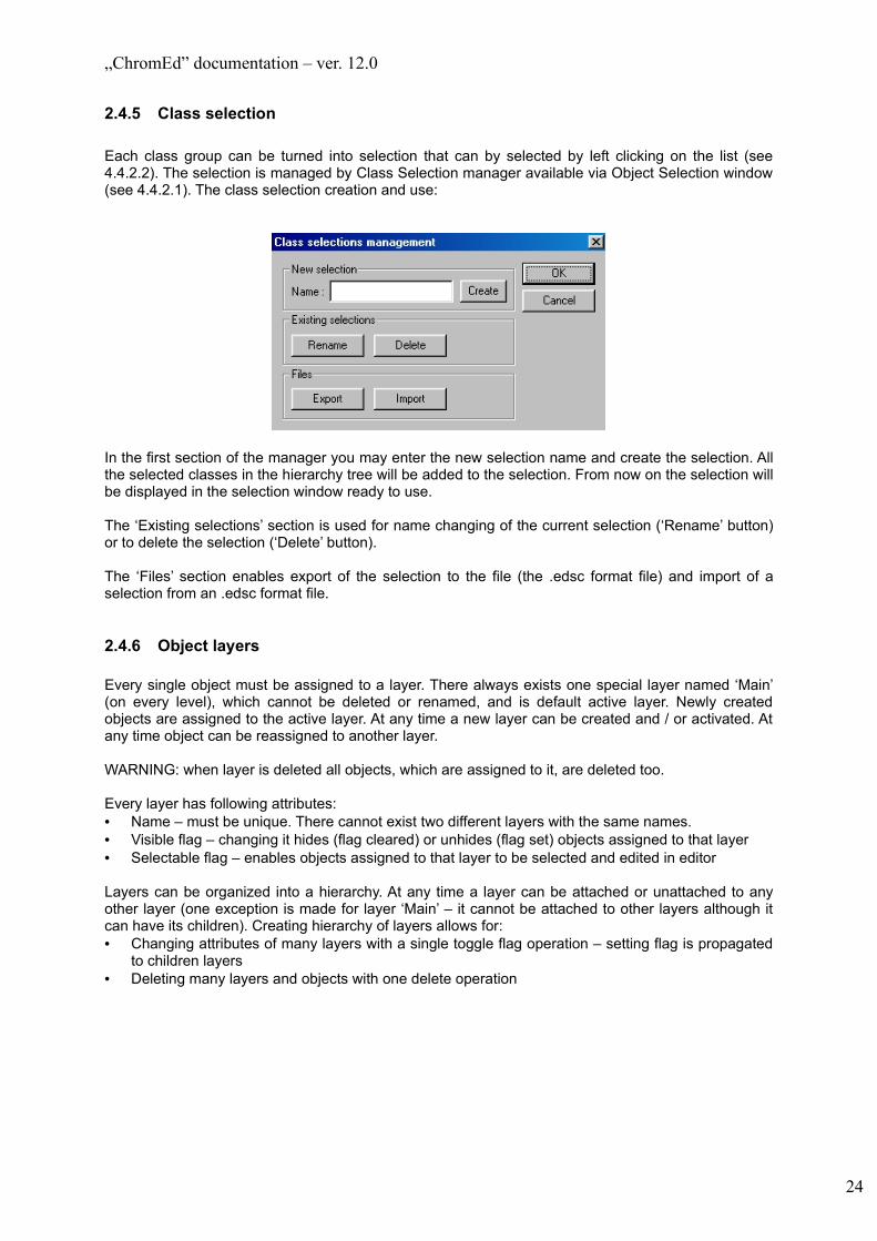
Each class group can be turned into selection that can by selected by left clicking on the list (see 4.4.2.2). The selection is managed by Class Selection manager available via Object Selection window (see 4.4.2.1). The class selection creation and use:
In the first section of the manager you may enter the new selection name and create the selection. All the selected classes in the hierarchy tree will be added to the selection. From now on the selection will be displayed in the selection window ready to use.
The ‘Existing selections’ section is used for name changing of the current selection (‘Rename’ button) or to delete the selection (‘Delete’ button).
The ‘Files’ section enables export of the selection to the file (the .edsc format file) and import of a selection from an .edsc format file.
2.4.6 Object layers
Every single object must be assigned to a layer. There always exists one special layer named ‘Main’ (on every level), which cannot be deleted or renamed, and is default active layer. Newly created objects are assigned to the active layer. At any time a new layer can be created and / or activated. At any time object can be reassigned to another layer.
WARNING: when layer is deleted all objects, which are assigned to it, are deleted too.
Every layer has following attributes:• Name – must be unique. There cannot exist two different layers with the same names.• Visible flag – changing it hides (flag cleared) or unhides (flag set) objects assigned to that layer• Selectable flag – enables objects assigned to that layer to be selected and edited in editor
Layers can be organized into a hierarchy. At any time a layer can be attached or unattached to any other layer (one exception is made for layer ‘Main’ – it cannot be attached to other layers although it can have its children). Creating hierarchy of layers allows for:• Changing attributes of many layers with a single toggle flag operation – setting flag is propagated
to children layers• Deleting many layers and objects with one delete operation
24

„ChromEd” documentation – ver. 12.0
Layers are managed via Layers Window:
There are following elements in this dialog:• A tree of layers – an existing layer hierarchy is presented here. There are two checkboxes for
every layer presented there. They enable to set flags ‘Visible’ and ‘Selectable’ for a layer. Using drag & drop operation (holding Ctrl key) layers can be attached to each other. Dropping on the empty part of the tree is equivalent to unattaching layer from its current parent.
• Button ‘+’ – creates new layer (via window Layer)• Button ‘-‘ – deletes selected layer• Button ‘Settings’ – enables to change selected layer attributes (via window Layer)• Button ‘Select objects’ – selects in editor all objects assigned to a layer. From that moment those
are the only selected objects.• Button ‘Deselect objects’ – deselects in editor all objects, that were selected and are assigned to a
layer. All other selected objects remain selected.
Creating and editing layers is managed via Layer Window:
There are all layer attributes presented in this dialog.
2.4.7 Setting the object attributes
Use ‘Objects attributes’ window to set the object attributes. It is a modeless dialogue used for setting the attributes of the selected objects (it supports the multiselection). If setting the object attributes is disabled it is signalized by displaying ‘<no valid objects selected>’ message in ‘Name’ edit field.
According to selected object various tabs are available:
25

„ChromEd” documentation – ver. 12.0
• Anims• Comment• Dyn. lights• Fields• Info• Java• Light (part of LightmapsEd plug-in – see 6.3)• Lighting (part of LightmapsEd plug-in – see 6.3)• Matrix• Mimic• Misc• Object• Skins
The tabs are available only when they concern all selected objects (even the most detailed common Java class of the selected object) and it is possible to manage multiple objects at the same time (does not apply to ‘Anims’ and ‘Indoors’ tabs.
In case only the level object is selected the following tabs are additionally available:• Comment (different then selecting single object)• Fog (part of Environment plug-in – see 6.1)• Sky (part of Environment plug-in – see 6.1)• Terrain (part of Environment plug-in – see 6.1)• Trees (part of Forester plug-in – see 6.2)• Varlist (part of Environment plug-in – see 6.1)• Water (part of Environment plug-in – see 6.1)
Elements that are always available (see 4.4.4.1):• ‘Name’ – enables to change the object name. it is active only in case of single object selection.
Theoretically, the objects may be of the same name, but it’s not advised due to work comfort. In case of multiselection the ‘<multiple selected>’ message is displayed. You cannot change the name of multiple objects at the same time.
• Object ID – right to the object name (‘---‘ in case of level object or multiselection)‘Class’ – displays the current object Java or native class or the base class in case of multiselection. Using the browse button (‘…’) you may choose the new class – the dialogue presented below will appear. The given class will be assigned to all selected objects (after clicking ‘Apply’ button). In case you choose Java class that does not have all the current class attributes and apply changes you lose all the current values (‘undo’ is not supported in that case).• ‘Parent’ – displays the parent object in hierarchy. Various parent objects are signalized by
‘<various meshes>’ message. The ‘X’ button is used for removing the selected objects from hierarchy.
• ‘Element’ – displays the name of a mesh element of the parent object this object is attached to. Various mesh elements are signalized by <different elements> message. Using browse button (‘...’) you may choose new mesh element to attach to.
• ‘Layer’ – combobox that shows current and enables to change layer this object is assigned to. It allows to set flags ‘Visible’ and ‘Selectable’ of all layers as well.
• ‘Load defs’ button – loads the default mesh data form .def format file• ‘Dump defs’ button – saves the default mash data to .def format file• ‘Refresh’ button – enables refreshing the selected objects settings• ‘Apply’ button – applies the changes
26

„ChromEd” documentation – ver. 12.0
The Change class window:
This window consists of the following elements:• On the left side there is the Java class tree that you may choose the new object class from. A root
of the tree is one of engine classes: CGSObject, CControlObject, CModelObject. It can be an abstract class as well. In such case it depends on a state of checkbox “advanced”.
• On the right side there is class list enabling to quick selection of the most frequently used classes. The list is created according to ‘EditorStart.ini’ file (see 3.4.2.1). Additionally, by using ‘’and ‘’ buttons you may add or remove the list elements. The changes will be stored in registry and be used while editor next initialization (the classes added in ‘EditorStart.ini’ are ALWAYS on the list).
• Edit “Mask” – it is used to set a mask, that determines which classes appear in a class tree. In case of typing any character as mask:• In the tree are listed only these classes, that names match the mask• All classes in tree are displayed as root classes (no hierarchy is presented)
• Checkbox “advanced” – enables to choose which of classes will be treated as root class:• closest abstract class in hierarchy (if there is any)• base engine classThis checkbox is important if a current class is derived from an abstract class (directly or indirectly). In such a case it determines the root of a tree of classes that can be chosen as a new object class. If it is checked the root is base engine class for a current object class. Otherwise it is the closest abstract class in hierarchy.
27

„ChromEd” documentation – ver. 12.0
The tabs description (only in the first part the whole window will be described, the further will be omitted):
2.4.7.1 ‘Anims’ tab
This tab is used for playing the object animations. Using the Anims tab you cannot create new animation frames but you may define the animation frames sequence. You may also view the given object mesh structure and also assign the proper animation sequence to the mesh (.scr format file).
The tab enables only the preview of the mesh structure of the object on the level that make easer the Java code creation responsible for object behavior (mostly animation).
The picture below shows the tab and the whole ‘Object attributes’ window (the following tabs will be presented without the window):
28
„ChromEd” documentation – ver. 12.0
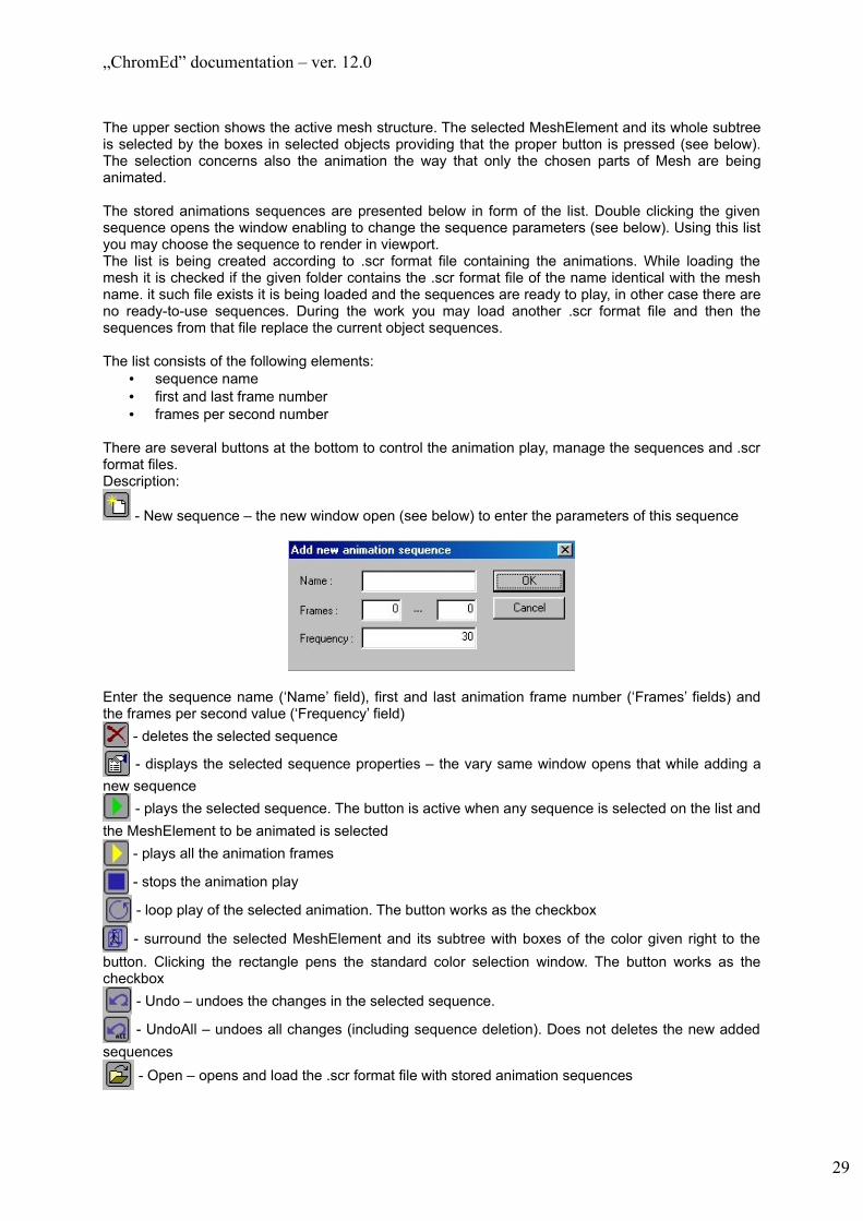
The upper section shows the active mesh structure. The selected MeshElement and its whole subtree is selected by the boxes in selected objects providing that the proper button is pressed (see below). The selection concerns also the animation the way that only the chosen parts of Mesh are being animated.
The stored animations sequences are presented below in form of the list. Double clicking the given sequence opens the window enabling to change the sequence parameters (see below). Using this list you may choose the sequence to render in viewport.The list is being created according to .scr format file containing the animations. While loading the mesh it is checked if the given folder contains the .scr format file of the name identical with the mesh name. it such file exists it is being loaded and the sequences are ready to play, in other case there are no ready-to-use sequences. During the work you may load another .scr format file and then the sequences from that file replace the current object sequences.
The list consists of the following elements:• sequence name• first and last frame number• frames per second number
There are several buttons at the bottom to control the animation play, manage the sequences and .scr format files.Description:
- New sequence – the new window open (see below) to enter the parameters of this sequence
Enter the sequence name (‘Name’ field), first and last animation frame number (‘Frames’ fields) and the frames per second value (‘Frequency’ field)
- deletes the selected sequence
- displays the selected sequence properties – the vary same window opens that while adding a new sequence
- plays the selected sequence. The button is active when any sequence is selected on the list and the MeshElement to be animated is selected
- plays all the animation frames
- stops the animation play
- loop play of the selected animation. The button works as the checkbox
- surround the selected MeshElement and its subtree with boxes of the color given right to the button. Clicking the rectangle pens the standard color selection window. The button works as the checkbox
- Undo – undoes the changes in the selected sequence.
- UndoAll – undoes all changes (including sequence deletion). Does not deletes the new added sequences
- Open – opens and load the .scr format file with stored animation sequences
29
„ChromEd” documentation – ver. 12.0
At the bottom there is the name of the current .scr format file displayed.
2.4.7.2 ‘Comment’ tab
This tab enables to enter the comment to the object. The comment may be various text.This tab is in face large edit field, so it is not presented here.
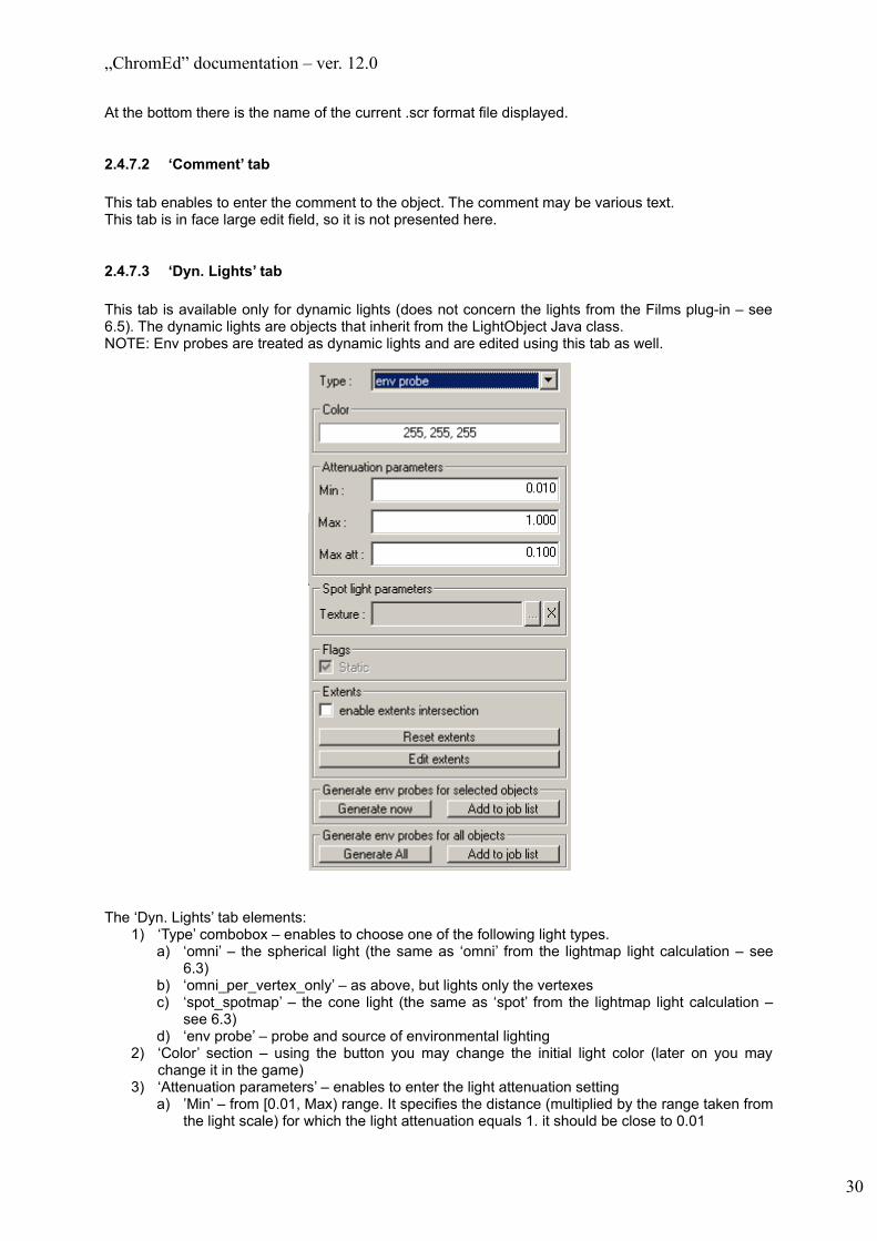
2.4.7.3 ‘Dyn. Lights’ tab
This tab is available only for dynamic lights (does not concern the lights from the Films plug-in – see 6.5). The dynamic lights are objects that inherit from the LightObject Java class.NOTE: Env probes are treated as dynamic lights and are edited using this tab as well.
The ‘Dyn. Lights’ tab elements:1) ‘Type’ combobox – enables to choose one of the following light types.
a) ‘omni’ – the spherical light (the same as ‘omni’ from the lightmap light calculation – see 6.3)
b) ‘omni_per_vertex_only’ – as above, but lights only the vertexesc) ‘spot_spotmap’ – the cone light (the same as ‘spot’ from the lightmap light calculation –
see 6.3)d) ‘env probe’ – probe and source of environmental lighting
2) ‘Color’ section – using the button you may change the initial light color (later on you may change it in the game)
3) ‘Attenuation parameters’ – enables to enter the light attenuation settinga) ’Min’ – from [0.01, Max) range. It specifies the distance (multiplied by the range taken from
the light scale) for which the light attenuation equals 1. it should be close to 0.01
30

„ChromEd” documentation – ver. 12.0
b) ‘Max’ – from (Min, 1] range. Similar to ‘Min’ value, but for this distance the attenuation reaches the value set in next parameter
c) ‘Max att’ – from (Min | Max, 1) range. It specifies the attenuation required for the distance specifies by ‘Max’ value
4) ‘Flags’ section – light flagsa) ‘Static’ – this flag should be set for those lights that position remains unchanged during the
game and the range (taken by the object scale) remains the same in condition to the initial range (though it may fluctuate in time)
5) ‘Extents’ section – enables to setup an extent used to test if an object is to be lightened by this light. This is not always the same extent, which is calculated using the light matrix (although by default these two extents are identical). a) ‘enable extents intersection’ checkbox – if set extent to test objects is clipped to main
object extentb) ‘Reset extents’ button – resets extent to test objects to default state (equal to extent
calculated using matrix)c) ‘Edit extents’ – allows to edit extent to test objects. When this button is pushed a box is
created. It can be moved and / or resized. When it is deselected its extent is stored as new extent to test objects of this light.
6) Generate env probes for selected objects – generates env probe data for selected lights (it is relevant only for lights of env probe type).a) ‘Generate now’ button – starts generation immediatelyb) ‘Add to job list’ – adds generation process to job list. No calculations are made at this
moment. NOTE: generation will be processed for objects selected at the moment this button is pressed.
7) Generate env probes for all objects – same as previous section, but generates for all existing env probes (not only selected ones).
31

„ChromEd” documentation – ver. 12.0
2.4.7.4 ‘Info’ tab
This tab is available only in case of selection of single object with a mesh (classes derived from CModelObject or MeshObject).
This tab shows which materials are used by the given object. It presents also the internal structure of these materials. A structure of a material is as follows:material -> techniques -> shaders -> passes -> vertex shader, pixel shader, samplers -> texture.For each of these elements different data are presented:1. Materials:
a) File nameb) Surface identifierc) Surface flags (if set)
2. Techniques:a) Name
3. Shaders:a) Quality [0;3]b) Version name
4. Passes:a) Order numberb) Indicator ‘light’ for light passesc) Types of lights that can be used in passes. For light passes – if there is no light of such type
pass is not used in rendering.5. Samplers:
a) Identifier of texture in pixel and vertex shaders assembly code (not in HLSL code)6. Textures:
32

„ChromEd” documentation – ver. 12.0
a) File name
Using ‘Sort by textures’ checkbox control tree can be toggled between two forms. One form has already been presented – it is a form, where materials are roots of hierarchy and pixel shaders, vertex shaders and textures are leaves. The other form has textures as roots and for each texture context of its use is listed. It enables quick orientation in the textures used in given object and the materials of the textures. It is presented below:
In case you select the texture in a tree texture view window is opened:
33

„ChromEd” documentation – ver. 12.0
On the window title bar the texture path is displayed (in case the path is too long it is also being displayed as a tooltip). Under the texture there are the basic texture parameters that is the resolution, color depth and the type of storage (in this case the texture is compressed). The ‘RGB’ and ‘Alpha’ buttons enable to set the elements of textures to be displayed (of course it concerns only this window – it does not affect the game rendering).
In case you select vertex or pixel shader in a tree Shader window is opened:
It presents both HLSL shader code after preprocessing phase and assembly code.
2.4.7.5 ‘Fields’ tab
The games created using the Chrome Engine are written in Java. Because of that all object used in those games (they may be created dynamically during the game or set up using the editor) have Java class assigned. In many cases it will be predefined classes (by the engine) e.g. MeshObject, but basically each object in game has to have a class assigned that inherits from GameObject class (also the engine class) .
The attributes defined in Java classes are enabled to set in editor (after creation of the given object) providing that while declaring them some rules were obeyed. These rules are described in sec 8.
34

„ChromEd” documentation – ver. 12.0
There are following elements in this tab:- a list of edited attributes- Checkbox “display advanced attributes” – toggles visibility of attributes that have been marked as
‘advanced’ (see chapter 8.)
All attributes of object class (and its base class and so on) are presented on the list. They are grouped according to their categories (see chapter 8.). Categories can be expanded and collapsed to limit a number of visible attributes.
The list is divided into two columns:- Name – presents:
- names of attributes or categories- types of attributes- hierarchy of attributes – concerns mostly attributes that are pointers to objects or lists of
pointers to objects- contains buttons to expand / collapse (categories and some attributes)
- Value – presents:- values of attributes- controls that are used to edit value- additional information (for example in case of list of pointers to objects size of list is presented)
Value of an attribute may be marked as default using gray color (in case it was changed the black color is used). Default values are those that an object has immediately after its construction and before any operations have been made upon it.
35

„ChromEd” documentation – ver. 12.0
In case of editing many objects at the same time a situation often takes place when attributes have different values for particular objects. Those values are marked by ‘<different values>’ string. Any change of those attribute values are made for all objects.
Attributes that are pointers to objects are being edited in different ways taking into consideration objects they are pointing to. There are two possible situations:- pointers to abstract classes (objects that are pointed at are called ‘private’ – see chapter 9.)- pointers to all other classes (objects that are pointed at are called ‘public’ – see chapter 9.)
In case of pointers to public objects only the objects existing on the edited level can be chosen. The examples are:- meshes of all kind- waypoints- fight nodesEditing of such attributes is possible in following ways:- through a button to select objects from a list of all valid objects (BROWSE_OBJECT flag must be
used in an attribute declaration – see chapter 8.)- providing ID of an object (depends on EDIT flag)- using context menu of editor 3D viewport (pointing at object while the attribute is selected on the
list).
Editing of pointers to private objects takes place with use of combobox. First a class of an object has to be chosen. Then a new object is created for this attribute and all attributes of the newly created object become visible and editable.Examples of such objects are:- actions executed (pointers to Action)- conditions of action execution (pointers to Condition)
Additional elements of user interface that are connected with editing of attributes:- Copy attribute / Paste attribute – available through context menu. - Select object(s) – available through context menu. This option is available only for attributes that
are pointers or lists of pointers to public objects. When chosen it selects all pointed objects in editor (which in consequence stops editing of current object(s)).
- Select chain of objects – available through context menu. This option is available only for an attribute pointing at objects that have that attribute as well. When chosen it selects a chain (sequence) of objects (which in consequence stops editing of current object(s)).
- Delete object(s) – available through context menu or pressing ‘Delete’ key. This option is available only for attributes that are pointers or list of pointers. If a pointed object is a public one the attribute is emptied. If it is a pointer it becomes NULL pointer. If it is a list of pointers all pointers are removed from the list. If it is an element of the expanded list it is removed from the list. Delete operation has effect only on the attribute – public objects are never deleted during the process. If the attribute points at private object (for example action) then pointed object (action) is deleted and pointer becomes NULL pointer. In case of list of pointers all objects on list are deleted.
- Remove object from list – available through context menu. This option is available only for elements of list of pointers to objects. The element is removed from list. If it is a pointer to a private object it is deleted.
- Pressing ‘Insert’ key for pointers to private objects opens a window to choose a class for a pointed object. After the class has been chosen a new private object of that class is created.
- Pressing ‘Insert’ key for a list of pointers to private objects adds an empty (NULL) pointer to the list.
- Double-click with left mouse button on a category expands / collapses this category.- Double-click with left mouse button on an attribute that can be expanded (for example a list of
pointers, Vector) in the Name column expands / collapses of the attribute.- Double-click with left mouse button on a list of pointers in the Value column adds empty (NULL)
pointer to the list.- Pressing combination of ‘Shift’ + ‘Delete’ keys restores default value to an attribute and sets a flag
that signals that default value is to be used. If this flag had been set before it is cleared.
36
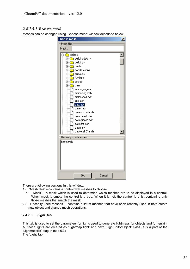
„ChromEd” documentation – ver. 12.0
2.4.7.5.1 Browse meshMeshes can be changed using ‘Choose mesh’ window described below:
There are following sections in this window:1) ‘Mesh files’ – contains a control with meshes to choose.
a. ‘Mask’ – a mask which is used to determine which meshes are to be displayed in a control. When mask is empty the control is a tree. When it is not, the control is a list containing only those meshes that match the mask.
2) ‘Recenlty used meshes’ – contains a list of meshes that have been recently used in both create new object and change mesh operations.
2.4.7.6 ‘Light’ tab
This tab is used to set the parameters for lights used to generate lightmaps for objects and for terrain. All those lights are created as ‘Lightmap light’ and have ‘LightEditorObject’ class. It is a part of the ‘LighmapsEd’ plug-in (see 6.3).The ‘Light’ tab:
37

„ChromEd” documentation – ver. 12.0
Description1) ‘Type’ – enables to choose the light source type from:
a) ‘Omni’ – (point light) – all directions are lighted evenlyb) ‘Spot’ – (cone light) – the light cone is defined and only those objects (a part of level) that are
in the way of this cone are lighted by this light. The cone vertex is located the same point as the light object and is directed according to current object rotation. For the ‘Spot’ light you need to set the additional parameters in group ‘Spot light properties’ (see below).
2) ‘Color’ – presents the light color and enables the color change – click the color bar. The ‘Is negative’ checkbox means that the light will not make objects lighter but darker
3) ‘Attenuation’ – the effect of light brightness decrease according to distance from the light source. The ‘Use’ checkbox enables to choose it you want to use this property or not. ‘Range’ specifies the value that light brightness reaches 0.
4) ‘Spot light properties’ – this section becomes available only if ‘Spot’ light type is selecteda) ‘HotSpot’ – the light cone angle of maximum brightness. This angle has to be lower or even
‘FallOff’ angle.b) ‘FallOff’ – the light cone angle defining the area of light disappearing, that is the area between
‘HotSpot’ and the area with no light (from this source). This angle must be higher or even the ‘HotSpot’ angle
5) Misc – miscellaneous settingsa) ‘Enabled’ – means that the light is on and affects the surroundingb) ‘render light range’ – specifies if the light range is being rendered in viewport (cones for ‘Spot’
and spheres for ‘Omni’) – see the rendering options 5.1)c) ‘Clear lighting model flag’ button – is available only when the light belongs to the object
lighting model. While changing the object lighting model all the lights belonging to the previous model are deleted and new model is inserted. Pressing this button removes the light from the object lighting model.
2.4.7.7 ‘Lighting’ tab
This tab is used for setting object lightmap generation parameters for selected objects. In case the level object is selected then the settings concerns the terrain lightmap generation. In such case this tab has a bit different layout – both layouts are presented and described below.
38

„ChromEd” documentation – ver. 12.0
This lightmap is a part of ‘LighMapsEd’ plug-in and more information about this tab can be found in this plug-in description (see 6.3)
2.4.7.7.1 Object layout
The tab consists of couple sections:1) ‘use default parameters’ checkbox – if set default parameters for lightmap generation for objects
are used (they are described in sec 6.3). In such case all the other controls with exception of ‘Lighting model’ section are disabled and cannot be set.
2) ‘Lighting output’ – contains two checkboxes that enable generation of classic lightmap (‘Texture’) and per vertex lighting (‘Vertex’). All combinations are allowed (with both checkboxes unset there is no output at all). NOTE: it depends on material whether effects of generation are visible or not.
3) ‘Lightmap parameters’ – contains the selected object lightmap generation parameters. In case of multiselection and other setting the edits might be empty, the checkbox is tri-state, the color button might be labeled as ‘Unidentified’. The change of one of the parameters effects in all selected objects.
39

„ChromEd” documentation – ver. 12.0
a) ‘use lightmaps’ checkbox – it must be checked if you want to generate the lightmap for the given object. NOTE: in some cases the lightmap is being generated automatically no matter if you press the ‘Generate’ button. It happens when e.g. the object is in a group and you choose to generate the lightmap for the group. So, for objects not to have the lightmap generated you should uncheck this checkbox.
b) ‘Samples per pixel’ – the sample per pixel quantity rendered while generating the result lightmap (the entered value is being squared – for ‘1’ only one sample will be calculated, for ‘2’ – four samples etc. – the result is average of all samples)
c) ‘Texels’ – number of texels per square meter of lightmapd) ‘Ambient occlusion’ subsection – contains parameters used in ambient occlusion calculations
• ‘Rays per texel’ – number of rays traced per texel (mentioned above) • ‘Ray length’ – length of each ray traced • ‘raytrace in both directions’ checkbox – enables raytrace in both directions
e) ‘Ambient’ subsection - the ambient color used while generating the lightmap for the selected objects• ‘use varlist ambient’ checkbox – if set, ambient is taken from varlist. If it is unset ambient
color can be changed using a color button.• color button – can be used to change ambient color if ‘use varlist ambient’ checkbox is
unset, otherwise it is disabledf) ‘RGB’ and ‘Alpha’ subsections – contain flags that enable or disable certain calculations to
store their results in rgb and alpha channels of lightmap respectively4) ‘Flags’ – flags used while lightmap calculation
a) ‘cast shadows’ – specifies if the selected object are to cast shadows. For those objects that might change the location or be destroyed during the game it is advised to turn this option off because in other case if the object locates or is destroyed the shadow remains
b) ‘receive shadows’ – specifies if the shadow is being cast on the object5) ‘Lights’ section – is used to select the lights to be concerned while generating the object lightmap
a) ‘use all editor lights’ checkbox – it concerns all light sources located in editor as objects (also the light form the object lighting model)
6) ‘Lighting model’ – this section is used to specify the object lighting model. The object lighting model is a predefined light set that can be loaded into object. The lighting models are connected with mesh (.3da format file) so the mesh change affects in deletion of light from the current lighting model. This section consists of:a) object lighting model list defined for the given mesh. In case different meshes are selected the
list is empty.b) ‘Load’ – loads the selected lighting model on the list and sets it as current for selected objectsc) ‘Save’ – available only for single object selection. All light linked in ControlObject hierarchy to
the selected object are stored in new lighting model for the given object.NOTE: you may enter the name of the object lighting model and those name are displayed on the list. Physically (on the disk) all the lighting models have the same name based on the .3da format file it concerns. E.g. for MurA.3da mesh the lighting models would be named MurA_0.lmf, MurA_1.lmf etc.
40
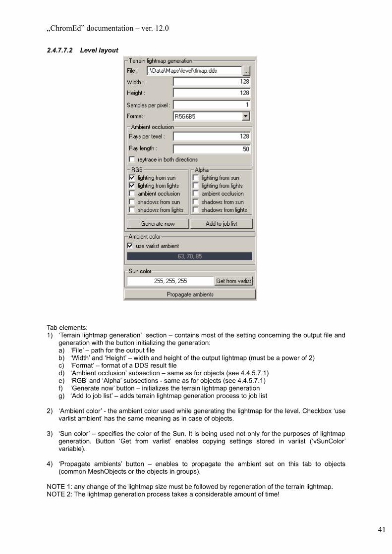
„ChromEd” documentation – ver. 12.0
2.4.7.7.2 Level layout
Tab elements:1) ‘Terrain lightmap generation’ section – contains most of the setting concerning the output file and
generation with the button initializing the generation:a) ‘File’ – path for the output fileb) ‘Width’ and ‘Height’ – width and height of the output lightmap (must be a power of 2)c) ‘Format’ – format of a DDS result filed) ‘Ambient occlusion’ subsection – same as for objects (see 4.4.5.7.1)e) ‘RGB’ and ‘Alpha’ subsections - same as for objects (see 4.4.5.7.1)f) ‘Generate now’ button – initializes the terrain lightmap generationg) ‘Add to job list’ – adds terrain lightmap generation process to job list
2) ‘Ambient color’ - the ambient color used while generating the lightmap for the level. Checkbox ‘use varlist ambient’ has the same meaning as in case of objects.
3) ‘Sun color’ – specifies the color of the Sun. It is being used not only for the purposes of lightmap generation. Button ‘Get from varlist’ enables copying settings stored in varlist (‘vSunColor’ variable).
4) ‘Propagate ambients’ button – enables to propagate the ambient set on this tab to objects (common MeshObjects or the objects in groups).
NOTE 1: any change of the lightmap size must be followed by regeneration of the terrain lightmap.NOTE 2: The lightmap generation process takes a considerable amount of time!
41

„ChromEd” documentation – ver. 12.0
The lightmap generation process is being presented on the status bar.
2.4.7.8 ‘Matrix’ tab
This tab is used for modifications of the selected objects transformation matrix parameters.The values in this matrix concern the ‘pivot point’ that is the one set point of the object representing the object location. If there are many selected objects then the position of pivot point is averaged from positions of all of them.
The tab construction:
Description:• in the upper part there is a 3x3 matrix defining the translation like position (‘Position’), rotation
(‘Rotation’) and scaling (‘Scale) in each of the axes (x, y, z). The rotation is in the given axis. The edition may be conducted in two ways: you may enter the new value in edit field or you may use the windows GUI element for changing the values. The difference is that the values entered in the second way are immediate visible in the viewport.
• ‘Spiners steps’ section – defines the step for the value change with use of the windows GUI element for changing the values. For each transformation you may specify a different step.
• ‘Primary scale’ – specifies the scaling factor for the whole object in all axes. Entering the value other then ‘1’ and clicking ‘Apply’ results in changing the object scale (the object dimensions are multiplied by the factor) and then the factor is being set to ‘1’. Using the windows GUI element to change the values does not result in automatic update in viewport.
• ‘C’, ‘P’ and ‘R’ buttons next to each column name enables to:o ‘C’ (copy) – copies the column values to the column clipboard (each column has own
clipboard);o ‘P’ (paste) – pastes the values prom the column clipboardo ‘R’ (reset) – resets the column values (for rotate and position the values are set to ‘0’,
for scale column ‘1’)• ‘Whole Matrix’ section – ‘Copy’, ‘Paste’ and ‘Reset’ buttons have the same purpose as ‘C’, ‘P’
and ‘R’ buttons of the column but they concern the whole matrix
2.4.7.9 ‘Mimics’ tab
This tab allows to see all facial expressions defined for mesh of selected object (these data are stored in ‘name_of_mesh.fed’ file). Choosing an expression in editor has no impact on game – no information is stored in map file.
42

„ChromEd” documentation – ver. 12.0
Selecting an expression name on list results in applying it to selected object. ‘Clear mimic’ button sets default facial expression for an object.
2.4.7.10 ‘Misc’ tab – object layout
In this tab miscellaneous settings are made. First of all there are LOD and visibility settings. There are two tabs in ‘Level of detail’ section. First, titled ‘Object’, contains settings for selected objects – it has been described below. Second, titled ‘Default’, contains settings for all objects. It has not been presented here, because of its similarity to ‘Object’ tab.
43

„ChromEd” documentation – ver. 12.0
Description:• ‘Level of detail’ section – is used to set the level of detail and visibility ranges of objects. There
are following subsections:o ‘Geometry’ – contains settings concerning level of detail of geometry:
‘LOD count’ – number of LODs of this object ‘use default parameters’ – enables to use parameters set in ‘Default’ tab ‘1st’, ‘2nd’, ‘3rd’ – LOD distances. Objects that are closer to a camera than ‘1st’ [cm] are
displayed at LOD 0. At ‘1st’ LOD 0 is changed to LOD 1, at ‘2nd’ LOD 1 is changed to LOD 2, at ‘3rd’ LOD 2 is changed to LOD 3 that is active up to a visibility range.
o ‘Shaders’ – contains settings with similar meaning that those in ‘Geometry’ subsection but they concern shaders.
o ‘Visibility range’ – contains visibility range settings: ‘use default parameters’ – enables to use parameters set in ‘Default’ tab ‘Visibility range’ – distance, from camera to object, at which object is no longer rendered ‘Blend distance’ – distance, from camera to object, at which objects starts to fade out (it
depends on the object material though)• ‘Mesh color’ – is used for setting the mesh color that can be used in materials• ‘auto align to ground in editor’ checkbox – turns on/off the automatic aligning object to the
ground• ‘enable physics in editor’ checkbox – enables physics to have any influence on that object in
editor (this flag has no influence on game)
44
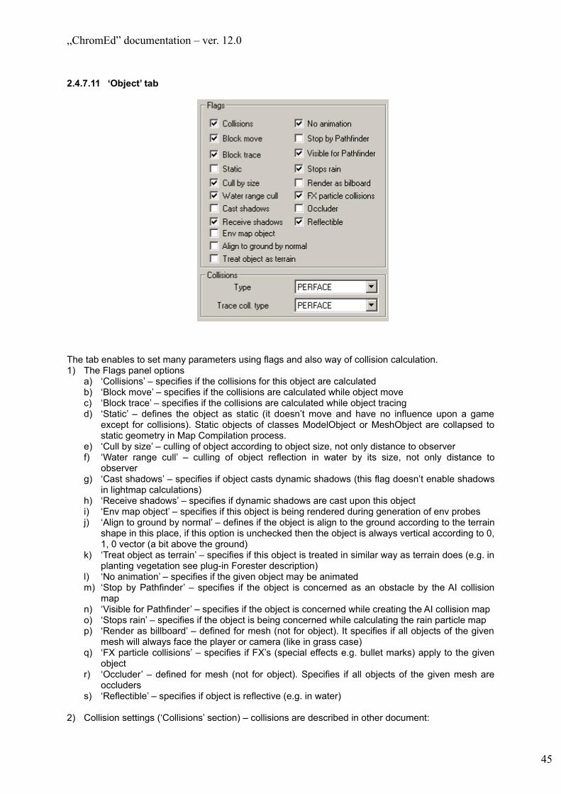
„ChromEd” documentation – ver. 12.0
2.4.7.11 ‘Object’ tab
The tab enables to set many parameters using flags and also way of collision calculation.1) The Flags panel options
a) ‘Collisions’ – specifies if the collisions for this object are calculatedb) ‘Block move’ – specifies if the collisions are calculated while object movec) ‘Block trace’ – specifies if the collisions are calculated while object tracingd) ‘Static’ – defines the object as static (it doesn’t move and have no influence upon a game
except for collisions). Static objects of classes ModelObject or MeshObject are collapsed to static geometry in Map Compilation process.
e) ‘Cull by size’ – culling of object according to object size, not only distance to observerf) ‘Water range cull’ – culling of object reflection in water by its size, not only distance to
observerg) ‘Cast shadows’ – specifies if object casts dynamic shadows (this flag doesn’t enable shadows
in lightmap calculations)h) ‘Receive shadows’ – specifies if dynamic shadows are cast upon this object i) ‘Env map object’ – specifies if this object is being rendered during generation of env probesj) ‘Align to ground by normal’ – defines if the object is align to the ground according to the terrain
shape in this place, if this option is unchecked then the object is always vertical according to 0, 1, 0 vector (a bit above the ground)
k) ‘Treat object as terrain’ – specifies if this object is treated in similar way as terrain does (e.g. in planting vegetation see plug-in Forester description)
l) ‘No animation’ – specifies if the given object may be animatedm) ‘Stop by Pathfinder’ – specifies if the object is concerned as an obstacle by the AI collision
mapn) ‘Visible for Pathfinder’ – specifies if the object is concerned while creating the AI collision mapo) ‘Stops rain’ – specifies if the object is being concerned while calculating the rain particle mapp) ‘Render as billboard’ – defined for mesh (not for object). It specifies if all objects of the given
mesh will always face the player or camera (like in grass case)q) ‘FX particle collisions’ – specifies if FX’s (special effects e.g. bullet marks) apply to the given
objectr) ‘Occluder’ – defined for mesh (not for object). Specifies if all objects of the given mesh are
occluderss) ‘Reflectible’ – specifies if object is reflective (e.g. in water)
2) Collision settings (‘Collisions’ section) – collisions are described in other document:
45

„ChromEd” documentation – ver. 12.0
α) ‘Type’ – possible values: ELLIPSOID, PERFACEβ) ‘Trace coll. Type’ – possible values: COARSE_BOX, COARSE_ELLIPSOID,
ELEMENT_BOX, ELEMENT_ELLIPSOID, PERFACE, EXTENTS
2.4.7.12 ‘Skins’ tab
The tab is available only if object with the very same mesh are selected. All skins (you may find the skin description in 3.6) defined for this .3da (.msh) object are displayed on the list in section ‘Skins’. In the tree labeled ‘Default skin (mesh)’ there are presented the original materials of the .3da (.msh) object. The tree labeled ‘Current skin’ displays the current materials of the .3da (.msh) object. In case of multiselection the ‘Current skin’ tree may be empty if the skins differ. Then none element on the list is selected. To update the ‘Current skin’ tree click ‘Apply’.
The ‘Current skin’ tree contains the information about what MeshElements are hidden (HIDE)and excluded from collisions (NO COLLISION).
Clicking the list element you change the skin for all selected objects (no need to click ‘Apply’). If you have selected many objects and you want to assign them various skins then click ‘Randomize skins’ and the following window opens:
46

„ChromEd” documentation – ver. 12.0
By using this window you may choose the group of the skins to randomize for the selected objects. Each randomization is separate with the equal probability for all skins.
2.4.7.13 ‘Comment’ tab
This tab is available if the single object is selected (or the level). It enables to add the comments to the object (it will be stored in .map format file). In case of the level also the data of the last saving, user name and computer name is stored
47
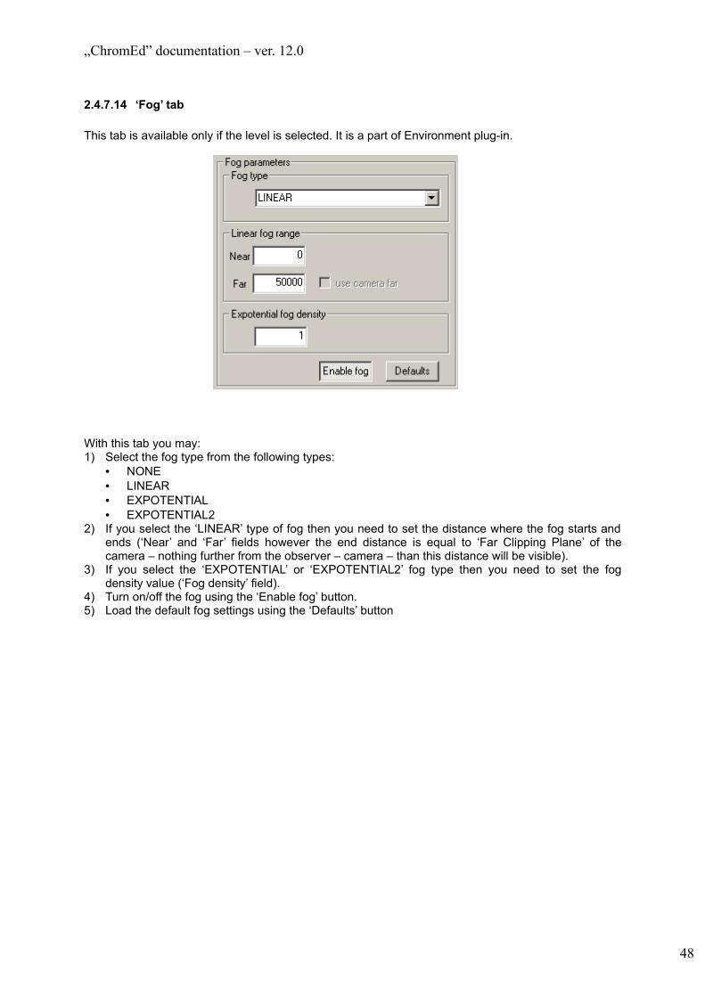
„ChromEd” documentation – ver. 12.0
2.4.7.14 ‘Fog’ tab
This tab is available only if the level is selected. It is a part of Environment plug-in.
With this tab you may:1) Select the fog type from the following types:
• NONE• LINEAR• EXPOTENTIAL• EXPOTENTIAL2
2) If you select the ‘LINEAR’ type of fog then you need to set the distance where the fog starts and ends (‘Near’ and ‘Far’ fields however the end distance is equal to ‘Far Clipping Plane’ of the camera – nothing further from the observer – camera – than this distance will be visible).
3) If you select the ‘EXPOTENTIAL’ or ‘EXPOTENTIAL2’ fog type then you need to set the fog density value (‘Fog density’ field).
4) Turn on/off the fog using the ‘Enable fog’ button.5) Load the default fog settings using the ‘Defaults’ button
48

„ChromEd” documentation – ver. 12.0
2.4.7.15 ‘Sky’ tab
This tab is available In case the level is selected. It is a part of the Environment plug-in.
Using this tab you may:1) Enable or disable sky (‘Enable’ checkbox in ‘Sky’ section) – this affects rendering of sky, sun and
blind effect2) Set mesh of the sky (‘Sky mesh’)3) Set position of the sky mesh in world coordinates (‘Position’)4) Set the horizon radius (‘Horizon radius’)– it is a kind of scale factor. Assuming that sky mesh is of
shape of a sphere or a cylinder it is a radius of this solid in XZ plane (Y is up).5) Enable or disable sun (‘Enable’ checkbox in ‘Sun’ section) – this affects rendering of sun and blind
effect6) Set the Sun location – enter the sun position angle in XZ plane (left – right, ‘Angle in XZ’ field) and
YZ (up – down, ‘Angle in YZ’ field). 7) Specify the flare FX of the Sun (you may click ‘…’ to browse for .fx file)8) Specify if the Sun blinding effect is on (‘Blind effect’ section – ‘Enable’ checkbox)9) Enable or disable blind effect (‘Enable’ checkbox in ‘Blind effect’ section) – this affects only blind
effect of sun10) Enter the blinding FX (you may click ‘…’ to browse for .fx file)11) Load the default sky settings using the ‘Defaults’ button
NOTE 1: For sun to be rendered both ‘Enable’ checkboxes from ‘Sky’ and ‘Sun’ sections need to be enabled.NOTE 2: For blind effect to be rendered all three ‘Enable’ checkboxes need to be enabled.
49

„ChromEd” documentation – ver. 12.0
2.4.7.16 ‘Terrain’ tab
This tab is available in case the level is selected. It is a part of the Environment plug-in.
Using this tab you may enter both the terrain parameters to create the terrain (providing it doesn’t exists yet) and change the existing terrain parameters:1) ‘Enable’ checkbox – specifying if the terrain is being rendered2) HeightMap file path (‘HeightMap’) – determining the terrain shape3) Lightmap file path (‘Lightmap’) – it is used for tree and movable objects (e.g. the player, AI.
Vehicles) shading
Both files may be of standard, recognized by ChromeEd file formats. The allowed bitmaps must be of 8-bit or 24-bit color resolution
4) Materials to render:a) ‘Terrain’ – the base terrain materialb) ‘Horizon’ – the horizon material – it is used to render the plane Y=0
5) ‘Render horizon’ checkbox – specifying if the horizon is being rendered6) Terrain size – in the following fields enter the terrain size in X, Y and Z axes. The terrain
boundaries are specified by vectors (0,0,0) – (X,Y,Z). 100 units = 1 meter7) The factor determining the detail map density (Detail Map). The value in ‘Detail Tile’ field specifies
how many times the map is copied in X and Z axes. In other words – value ‘1’ means that the DetailMap is being mapped on the terrain without copying, value ‘2’ means that the map will be copied onto quarter of the map (1/2 in both X and Z axes) etc.
8) The factor used to changing the terrain LODs (Level of details) – ‘Geom error’ field
The ‘Object grid sizes’ section contains the Object grid parameters:• Grid boundaries (the rectangle specified by the values in ‘Minimum’ and ‘Maximum’ edit fields).
Most often the grid is equal to the terrain size. To set the terrain size values into these filed click ‘Get extents from terrain’NOTE: All objects must be located inside the grid
• Grid cell size in X and Z axes
50

„ChromEd” documentation – ver. 12.0
By clicking ‘Apply’ you reload the bitmaps of a different paths or bitmaps that have been changed. The terrain re-initialization may happen only in cases of:• HeightMap change• Terrain size change
2.4.7.17 ‘Trees’ tab
This tab is available in case level is selected. It is a part of the Environment plug-in.Using this tab you may set basic parameters of trees and grass grids – size of their cells. An assumption: grid is equal to or greater than terrain. In case of grass grid cells are square, it is not required for trees grid.
2.4.7.18 ‘Varlist’ tab
Varlist is a set of parameters used mostly in rendering and particularly in materials. It is defined in a ‘data/varlist.scr’ file. There are default settings used for all maps there. Besides for each map there exists a file with settings that are used for that map only (these settings overwrite those defined in ‘data/varlist.scr’). Default name of that file is map_name.scr but it can be changed using the editor. There also exists ‘data/varlist_descriptions.scr’ file which has meaning only for ChromEd and defines a way of editing all varlist parameters in the same way it is done with Java attributes.
ChromEd does not make full varlist editing possible. It allows only for changing values of parameters existing in a loaded map varlist file. It is not possible to:- add new parameters to that file- remove parameters from it- change default value of any parameter (they are stored in ‘data/varlist.scr’).
51

„ChromEd” documentation – ver. 12.0
Elements of this tab:- A list of parameters to edit- ‘Renderer variable script file path’ – a path to a file with varlist settings for this map- Button ‘...’ – use it to browse for a file- Button ‘Load...’ – enables to select and load a file with varlist settings. It does not mean that the
chosen file will be used as a file with settings for this map.- Button ‘Save’ – saves current settings in the file pointed by ‘Renderer variable script file path’- Button ‘Save as...’ – enables to save settings to selected file. It does not mean that the chosen file
will be used as a file with settings for this map.
52

„ChromEd” documentation – ver. 12.0
2.4.7.19 ‘Water’ tab
This tab is available in case the level is selected. It is a part of the Environment plug-in.
Using this tab you may set the following water parameters:1) ‘Main setting’ section – water main settings:
a) ‘Enable’ checkbox – it is used to turn on/off the water rendering on the levelb) ‘Enable water horizon’ – it is used to turn on/off rendering of water horizonc) ‘Material’ field – it is used to specify the water material file path. Right to the field there is the
browsing button enabling the material selection in the standard Open file dialogued) ‘Scale tile’ field – enables to specify the texture mapping type. It is a factor enabling to set the
texture location while mapping onto the water2) ‘Extent’ section – the water extents
a) ‘Level’ field – the water level in Y plane set in game scale units (100 units = 1m). The lowest value is ‘0’
b) ‘Whole terrain’ ‘part of terrain’ radio button – specifies if the water is to be on the whole terrain or just a part of it. In case of ‘part of terrain’ selection the extent is taken from ‘From’ and ‘to’ fields:• the extent is squared so the ‘From’ value defines both the beginning in X and Z axes• the extent size is not any but is calculated this way:
size = (((To-From)/1000) up rounded to the nearest power of 2)*1000c) ‘Pick’ button – enables to set the extent by selecting it in viewport. It is available only if the
extent concerns a part of the terrain
53

„ChromEd” documentation – ver. 12.0
3) ‘Waves’ section – waves only occur in XZ plane (so the water is always a plane). You may set:a) Wave scaling in X and Z axis – it enables to set less regular shape of the wave (‘Scale’ field)b) Wave amplitude – the higher value in ‘Amplitude’ field, the higher wavesc) Wave speed – ‘Speed’ field
4) Turn on the water animation (‘Animations preview). You may set the required animations frame per second (FPS) and then turn on the animation (‘Start’ button) or stop the animation (‘Stop’ button). During the animation you may change the water settings and it is being updated automatically
5) ‘Underwater settings’ section – main setting of the underwater camera renderinga) ‘Sky is visible’ checkbox – specifies if the sky is being renderedb) ‘Blind plane color’ – the color of the quad on the screen. It enables to change the color
perspective under the water.6) ‘Underwater FOV wave’ section - Underwater FOV wave
a) ‘Speed’ – the horizontal(‘H’) and vertical (‘V’) speed of waves under the waterb) ‘Amplitude’ – the wave amplitude
7) ‘Underwater fog settings’ section – the underwater fog is generally LINEAR type (see 4.4.4.15)a) ‘Enable’ checkbox – specifies if the fog is on under the waterb) ‘Near’ and ‘Far’ fields specify the fog rangec) Fog color (the button at the bottom of the section)
2.4.8 Object hiding
By default, all the newly added objects to the level are visible and you may select them in the viewport. However for the great number of objects there is a danger of changing the objects that must remain unchanged (because if the way of selecting the objects by the viewport – see 6.4). To avoid such situations you may hide the objects – from now on these objects are not rendered (which fastens the editor itself) and cannot be selected in the standard way. You may select them (e.g. to unhide them) only by using the Object selection window – the ‘Hidden’ checkbox (see 4.4.2)
The objects may be hidden in two ways:• By using menu / toolbar options• By using the rendering options (for all objects of the given Java class located on the level) –
see 5.1
NOTE: Layers are an alternative way to prevent selecting of sets of objects, although there are certain situations, when only a subset of layer objects is to be changed. In such a situation pure object hiding is the best method to avoid unwanted selecting and changing of objects.
2.4.9 Object groups
Objects group are used to link object in the way that they are treated by the editor as one object. It concerns both selection and other transformations. Additionally, the object groups are used in portal systems (see 4.4.4.4) and while generating the lightmap (the ‘LightmapsEd’ plug-in – see 6.3)
A group may be in two states in editor: open or closed. If the group is closed then everything mentioned above concerns the group. Also you may not change the objects of the group (it is being treated as one object). The open group is treated as an object set and then you may add new objects to it or remove objects from it and also change the setting of the particular object (e.g. location, attributes, etc.).
54
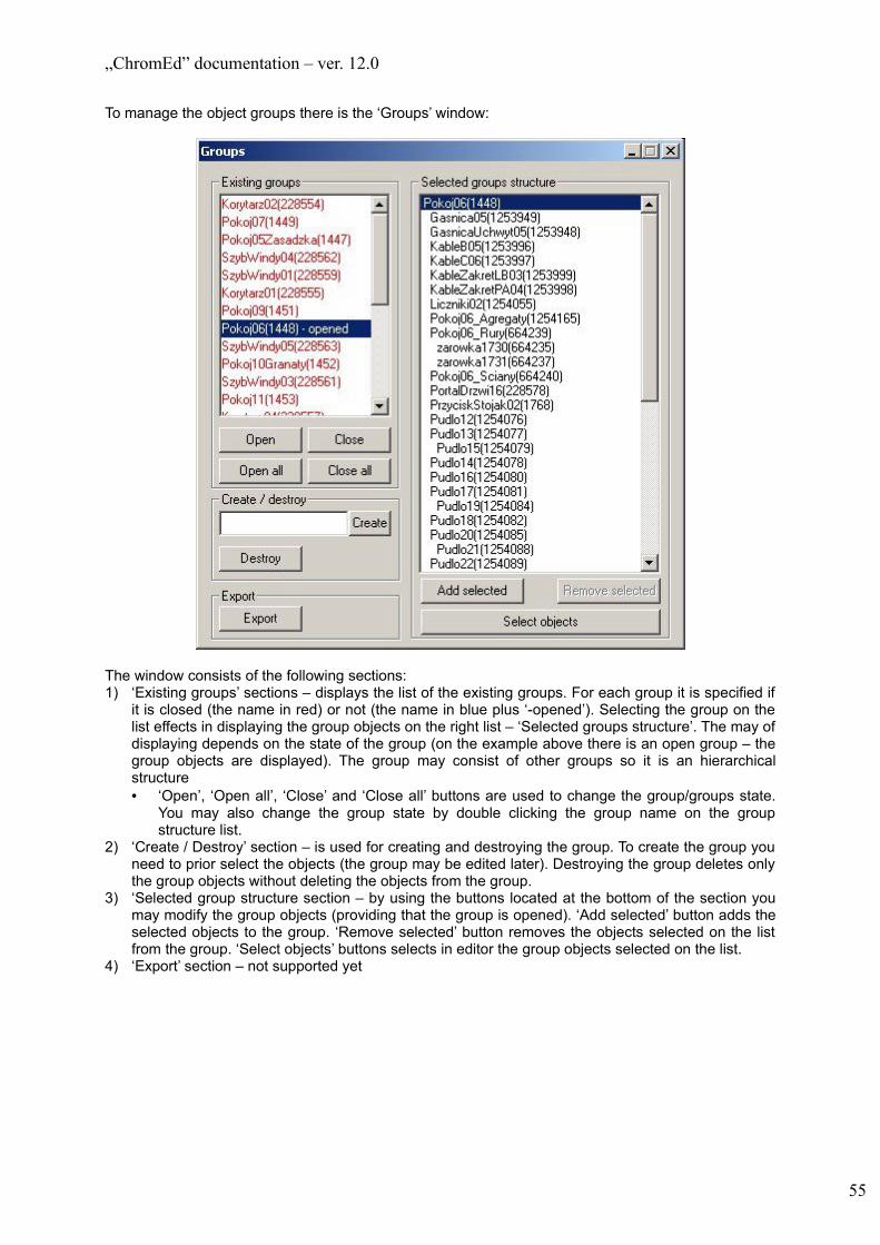
„ChromEd” documentation – ver. 12.0
To manage the object groups there is the ‘Groups’ window:
The window consists of the following sections:1) ‘Existing groups’ sections – displays the list of the existing groups. For each group it is specified if
it is closed (the name in red) or not (the name in blue plus ‘-opened’). Selecting the group on the list effects in displaying the group objects on the right list – ‘Selected groups structure’. The may of displaying depends on the state of the group (on the example above there is an open group – the group objects are displayed). The group may consist of other groups so it is an hierarchical structure• ‘Open’, ‘Open all’, ‘Close’ and ‘Close all’ buttons are used to change the group/groups state.
You may also change the group state by double clicking the group name on the group structure list.
2) ‘Create / Destroy’ section – is used for creating and destroying the group. To create the group you need to prior select the objects (the group may be edited later). Destroying the group deletes only the group objects without deleting the objects from the group.
3) ‘Selected group structure section – by using the buttons located at the bottom of the section you may modify the group objects (providing that the group is opened). ‘Add selected’ button adds the selected objects to the group. ‘Remove selected’ button removes the objects selected on the list from the group. ‘Select objects’ buttons selects in editor the group objects selected on the list.
4) ‘Export’ section – not supported yet
55

„ChromEd” documentation – ver. 12.0
2.4.10 Object selections
Object selections are used to simultaneous selection of multiple objects. Additionally, there is a possibility of adding an exported object selection to the level after loading the level. To manage the objects selection there is the ‘Selections’ window:
Description:• The list on the left contains the existing selections. Choosing the list element effects in selecting
the selection in window and all the selection objects in editor.• ‘Manipulate’ section – is used for selection manipulations. It consists of the following elements:
a) Edit field – it displays the selection name upon choosing it on the listb) ‘Create’ button – creates a new selection. All the currently selected objects are added to the
selection. The new selection is named due to the edit field (or the same name with the number suffix)
c) ‘Destroy’ button – destroys the selection – it does not affect the objects from the selectiond) ‘Rename’ button – enables to change the selection name. It is available only if one selection is
selected on the list. The new name is taken form the edit field.e) ‘Export’ button – enables to export the selection to the file. It is available only if one selection is
selected on the listf) ‘Select by objects’ button – selects all the selections on the list that consists of at least one of
the currently selected in editor objects• ‘Link with file’ section – enables to logical linking selection with file. The objects of such selection
are not saved with level but during the level saving they are automatically exported to the linked file. During saving the selection is not saved on the level so while re-loading the level the objects from the selection will not be on the level. Also there won’t be the selection itself. The change of the link is available only in case of single object selection.a) the browsing button ‘…’ enables to choose the file to linkb) ‘Unlink’ button – destroys the selection-file link
• The list on the right – all objects from the currently selected selections are being displayed on this list
• ‘Add selected’ button – available only if the single selection is selected. It adds all currently selected objects in editor to the selected selection
56
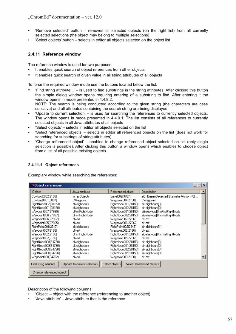
„ChromEd” documentation – ver. 12.0
• ‘Remove selected’ button – removes all selected objects (on the right list) from all currently selected selections (the object may belong to multiple selections).
• ‘Select objects’ button – selects in editor all objects selected on the object list
2.4.11 Reference window
The reference window is used for two purposes:• It enables quick search of object references from other objects• It enables quick search of given value in all string attributes of all objects
To force the required window mode use the buttons located below the list:• ‘Find string attribute...’ – is used to find substrings in the string attributes. After clicking this button
the simple dialog window opens requiring entering of a substring to find. After entering it the window opens in mode presented in 4.4.9.2.NOTE: The search is being conducted according to the given string (the characters are case sensitive) and all attributes containing the search string are being displayed
• ‘Update to current selection’ – is used for searching the references to currently selected objects. The window opens in mode presented in 4.4.9.1. The list consists of all references to currently selected objects in all Java attributes of all objects
• ‘Select objects’ – selects in editor all objects selected on the list• ‘Select referenced objects’ – selects in editor all referenced objects on the list (does not work for
searching for substrings of string attributes)• ‘Change referenced object’ – enables to change referenced object selected on list (only single
selection is possible). After clicking this button a window opens which enables to choose object from a list of all possible existing objects.
2.4.11.1 Object references
Exemplary window while searching the references:
Description of the following columns:• ‘Object’ – object with the reference (referencing to another object)• ‘Java attribute’ – Java attribute that is the reference.
57
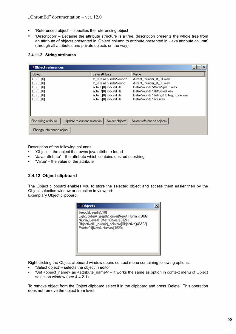
„ChromEd” documentation – ver. 12.0
• ‘Referenced object’ – specifies the referencing object• ‘Description’ – Because the attribute structure is a tree, description presents the whole tree from
an attribute of objects presented in ‘Object’ column to attribute presented in ‘Java attribute column’ (through all attributes and private objects on the way).
2.4.11.2 String attributes
Description of the following columns:• ‘Object’ – the object that owns java attribute found• ‘Java attribute’ – the attribute which contains desired substring• ‘Value’ – the value of the attribute
2.4.12 Object clipboard
The Object clipboard enables you to store the selected object and access them easier then by the Object selection window or selection in viewport:Exemplary Object clipboard:
Right clicking the Object clipboard window opens context menu containing following options:• ‘Select object’ – selects the object in editor• ‘Set <object_name> as <attribute_name>’ – it works the same as option in context menu of Object
selection window (see 4.4.2.1)
To remove object from the Object clipboard select it in the clipboard and press ‘Delete’. This operation does not remove the object from level.
58
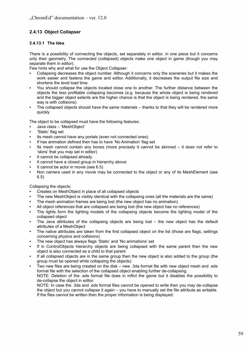
„ChromEd” documentation – ver. 12.0
2.4.13 Object Collapser
2.4.13.1 The Idea
There is a possibility of connecting the objects, set separately in editor, in one piece but it concerns only their geometry. The connected (collapsed) objects make one object in game (though you may separate them in editor).Few hints why and what for use the Object Collapser:• Collapsing decreases the object number. Although it concerns only the sceneries but it makes the
work easier and fastens the game and editor. Additionally, it decreases the output file size and shortens the level load time.
• You should collapse the objects located close one to another. The further distance between the objects the less profitable collapsing becomes (e.g. because the whole object is being rendered and the bigger object extents are the higher chance is that the object is being rendered, the same way is with collisions)
• The collapsed objects should have the same materials – thanks to that they will be rendered more quickly
The object to be collapsed must have the following features:• Java class – ‘MeshObject’• ‘Static’ flag set• Its mesh cannot have any portals (even not connected ones)• If has animation defined then has to have ‘No Animation’ flag set• Its mesh cannot contain any bones (more precisely it cannot be skinned – it does not refer to
‘skins’ that you may set in editor)• It cannot be collapsed already• It cannot have a closed group in hierarchy above• It cannot be actor in movie (see 6.5)• Non camera used in any movie may be connected to the object or any of its MeshElement (see
6.5)
Collapsing the objects:• Creates on MeshObject in place of all collapsed objects• The new MeshObject is visibly identical with the collapsing ones (all the materials are the same)• The mesh animation frames are being lost (the new object has no animation)• All object references that are collapsed are being lost (the new object has no references)• The lights form the lighting models of the collapsing objects become the lighting model of the
collapsed object• The Java attributes of the collapsing objects are being lost – the new object has the default
attributes of a MeshObject• The native attributes are taken from the first collapsed object on the list (those are flags, settings
concerning physics and collisions)• The new object has always flags ‘Static’ and ‘No animations’ set• If in ControlObjects hierarchy objects are being collapsed with the same parent then the new
object is also connected as a child to that parent• If all collapsed objects are in the same group then the new object is also added to the group (the
group must be opened while collapsing the objects)• Two new files are being created on the disk – new .3da format file with new object mesh and .eds
format file with the selection of the collapsed object enabling further de-collapsing.NOTE: Deletion of the .eds format file does in inflict the game but it disables the possibility to de-collapse the object in editor.NOTE: In case the .3da and .eds format files cannot be opened to write then you may de-collapse the object but you cannot collapse it again – you have to manually set the file attribute as writable. If the files cannot be written then the proper information is being displayed:
59

„ChromEd” documentation – ver. 12.0
De-collapsing objects:• It is possible only in case the object has the collapsing selection stored (in .eds format file)
NOTE: Using the copies of the collapsed object (e.g. by adding to the level the object with mesh created while collapsing the objects) is possible but you cannot de-collapse that copy
• All object that were collapsed go back to the level• All lights from the lighting model of the collapsing object are being checked. In object selection
lights are stored for all collapsing objects, but during de-collapsing only those lights are restored that were not deleted while collapsing the object (the light attributes also are not restored for the selection)
Generally speaking the de-collapsing process removes the de-collapsing object from the level and replaces it with the object selection. The only difference from adding the common object selection is that not all lights are being restored from the collapsed object.
2.4.13.2 User interface
This window consists of three sections:1) ‘(de)collapsed objects’ section – contains the list of collapsed and de-collapsed (previously
collapsed) objects and the buttons used for collapsing (de-collapsing). Section elements and their functions:a) Object list:
• The first object is always ‘<new> -d’ – it enables to create a new collapsed object, that is to specify the object set to be collapsed
• All objects displayed in red without ‘-d’ suffix are collapsed objects
60

„ChromEd” documentation – ver. 12.0
• All objects displayed in blue with ‘-d’ suffix (except ‘<new> -d’) are de-collapsed objects. Selecting a de-collapsed object activates ‘Collapse details’ section
b) ‘Decollapse’ button – clicking this button starts the process of de-collapsing the selected object (the same as double clicking the selected object)
c) ‘Collapse’ button – clicking the button starts the collapsing process for the selected object (the same as double clicking the selected object)
d) ‘Destroy’ button – destroys the collapsed object (does not deletes the objects)e) ‘Collapse all’ button – starts the collapsing process for all de-collapsed objects
2) ‘Collapse details’ section – enables modifications of the objects set ready to collapse to object selected on the list in ‘(de)collapsed objects’. The following elements are in this section:a) object list
Objects on the list may be displayed in black – which means they can be collapsed without any problems or in red – which means that the collapsing process may be difficult or impossible for given object.Selecting object on the list effects in yellow outlining it in the viewport (it is not identical with selecting in editor).For each object a tooltip is being displayed upon pointing it with cursor informing about any potential problems with collapsing. ‘Ok’ means that there are no problems and you may collapse the object. In any other case a detailed information will be displayed in this tooltip such as on the example below:
The object does not fulfill the requirements for the object to collapse (see 4.4.10.1)
b) ‘+’ button – adds the object selected in editor to object set (objects are being added even though they may not be collapsed later on)
c) ‘-‘ button – removes the selected object form the object setd) ‘Select trouble’ button – clicking this button selects all the troublesome objects on the list (and
the objects displayed in red on the list)e) ‘Select in editor’ button – selects in editor all objects selected on the list
3) ‘Selected collapse object parameters’ section – collapsing settingsa) ‘Vertex align threshold’ – vertex connecting threshold. The vertexes that are distant one from another less then the given threshold are connected during the collapsing process.
2.4.14 Running the game in editor
Running the game in editor saves the currently edited level and loads it in game mode. Unconditionally from the module classes the game runs in singleplayer mode. After exiting the game (ALT-F4) you may continue the level edition.
61

„ChromEd” documentation – ver. 12.0
2.4.15 Object selection groups management window (from the file)
This window supports loading the tracks defined with *.trk format files• ‘Script file’ section – enables selection of *.trk format file. The content of the file is displayed in the
tree below. By default it is ‘loaded_map_name.trk’ file• ‘Currently loaded group’ section – displays the currently loaded track• The tree with the track enables the track to load.• ‘Load’ button – closes the current track (if loaded) and loads the selected track• ‘Unload current’ button – closes the current track• ‘Close’ button – closes the window
While loading the track (‘Load’) all added object selection are still logically linked with files they come from and upon saving the level they will be saved in these files (they won’t be saved in *.map file). Unloading the loaded track effects in deletion the objects from this .eds from the level.
2.4.15.1 *.trk format file structure
The *.trk format files are the scripts defined for each *.map format file and contain the information about the tracks on this map. From the ChromeEd point of view the following keys are important:• Group(s) – the track name is given as the parameter. This key defines the track and groups the
rest of the keys• Objects(s) – the path to *.eds format file (that is the exported from level object group) is given as
the parameter
2.4.16 Object selection filtering
The window is presented below. You may filter the selection by the name or by the class name. To do so enter the filtering mask in ‘Mask’ filed and try to select the object (objects). Only the objects that pass through the mask are being selected (on the picture below – all objects of TrackPoint class).
62

„ChromEd” documentation – ver. 12.0
2.4.17 Process window
The process window contains the task list which the editor can perform automatically. The processes are always executed for the currently selected objects (providing that the process concerns the object). The window contains the following tasks:• ‘Calculate movie dialog length’ – dumps exact lengths of all dialogs in all movies to a given file• ‘Change meshes of objects’ – changes meshes of all existing objects using a given script file.
Script must contain keys ChangeMesh( s, s ). The first argument is a mesh path that is to be changed, the second one is a new mesh path. E.g. ChangeMesh( "barrel.msh", "boxwooden.msh" ) will change all meshes from ‘barrel.msh’ to ‘boxwooden.msh’.
• ‘Convert meshes from 3da to msh’ – converts all meshes that have .3da extension (old format) to they replacements of the same name but .msh extension (new format). If there is no such file no action takes place.
• ‘Export objects to STL format’ – exports geometry of objects to .stl format file.• ‘Export terrain to STL format’ – exports the terrain to .stl format file.• ‘Find default attributes’ – first it asks for a name of an attribute to find. Next it deselects all objects
that either don’t have any attribute of such name or that attribute does not have default value.• ‘Generate trees map’ – generates map of all trees on the level. First it shows dialog (presented
below) to gather all necessary data. Next it creates bitmap of given size with all trees marked on it.
• ‘Java method caller’ – calls java method of given name for selected objects.• ‘Numerical attributes randomizer’ – enables to generate the random value for object attributes. In
the dialog window you need to specify the attribute name and the value range
63
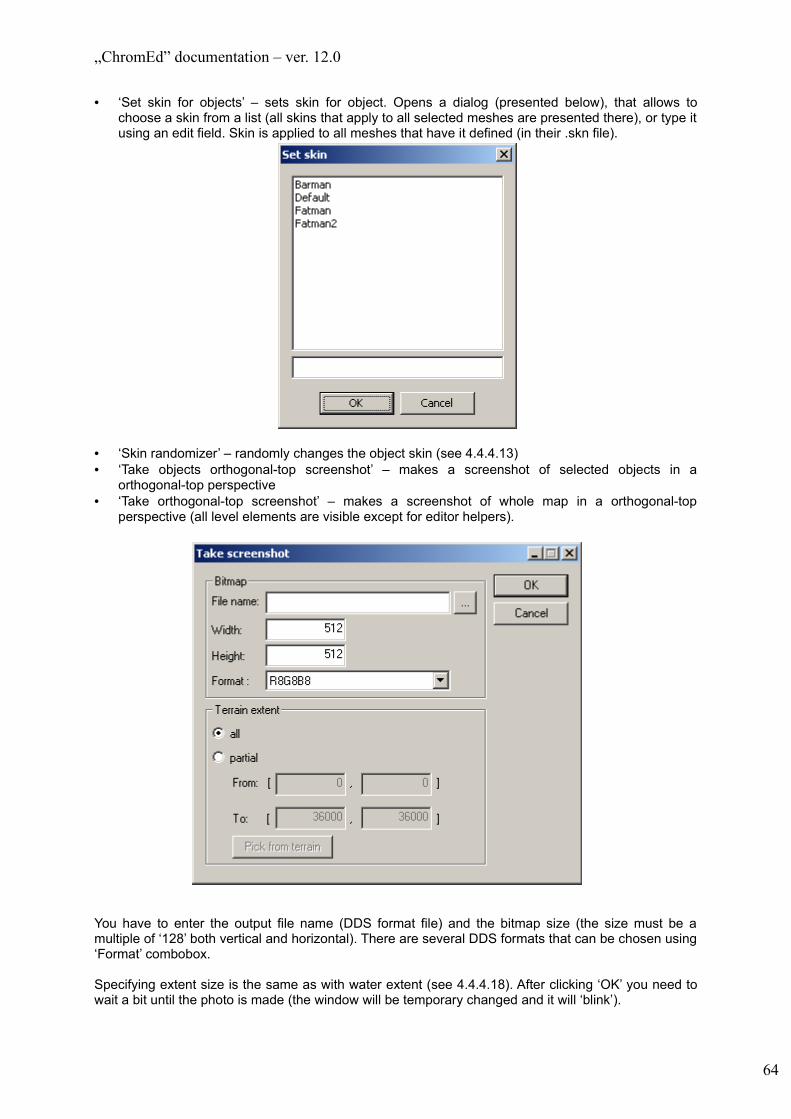
„ChromEd” documentation – ver. 12.0
• ‘Set skin for objects’ – sets skin for object. Opens a dialog (presented below), that allows to choose a skin from a list (all skins that apply to all selected meshes are presented there), or type it using an edit field. Skin is applied to all meshes that have it defined (in their .skn file).
• ‘Skin randomizer’ – randomly changes the object skin (see 4.4.4.13)• ‘Take objects orthogonal-top screenshot’ – makes a screenshot of selected objects in a
orthogonal-top perspective• ‘Take orthogonal-top screenshot’ – makes a screenshot of whole map in a orthogonal-top
perspective (all level elements are visible except for editor helpers).
You have to enter the output file name (DDS format file) and the bitmap size (the size must be a multiple of ‘128’ both vertical and horizontal). There are several DDS formats that can be chosen using ‘Format’ combobox.
Specifying extent size is the same as with water extent (see 4.4.4.18). After clicking ‘OK’ you need to wait a bit until the photo is made (the window will be temporary changed and it will ‘blink’).
64

„ChromEd” documentation – ver. 12.0
The photos are made in ‘TOP’ orthogonal view and zooming is made automatically to fit the whole extent in the bitmap
• ‘Take perspective screenshot’ – as ‘Take orthogonal-top screenshot’, but it does not enable orthogonal-top perspective
You have to enter the output file name (TGA format file) and the bitmap size (the size must be a multiple of ‘256’ both vertical and horizontal).
2.4.18 Screenshot window
The screenshot window displays the screenshots made during the game and stored in .scr format files. Thanks to that you may set the camera in editor the same way it was set while taking the screenshot (providing that the same level is selected)
2.4.19 Collapsing with cell division
This tool is very similar to common object collapsing but here the selected objects are divided into cells with the set (in the dialogue window) dimension and only those objects are collapsed that are in the same cells
2.4.20 Job list
Job lists serve to execute several actions (processes) one after another. Their main purpose is to queue time consuming tasks to avoid the need of constant monitoring whether previous task has finished and it is time to start next.
Processes that are gathered on the job list need not to work on the same map. Another map will be automatically loaded if necessary. If a map needs to be saved, after a task has finished processing, a backup copy of a map file is made before save operation is performed.
65
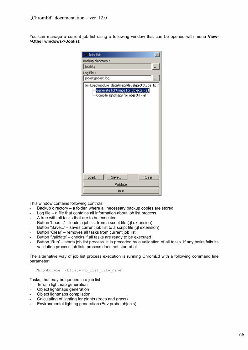
„ChromEd” documentation – ver. 12.0
You can manage a current job list using a following window that can be opened with menu View->Other windows->Joblist:
This window contains following controls:- Backup directory – a folder, where all necessary backup copies are stored- Log file – a file that contains all information about job list process - A tree with all tasks that are to be executed- Button ‘Load...’ – loads a job list from a script file (.jl extension)- Button ‘Save...’ – saves current job list to a script file (.jl extension)- Button ‘Clear’ – removes all tasks from current job list- Button ‘Validate’ – checks if all tasks are ready to be executed- Button ‘Run’ – starts job list process. It is preceded by a validation of all tasks. If any tasks fails its
validation process job lists process does not start at all.
The alternative way of job list process execution is running ChromEd with a following command line parameter:
ChromEd.exe joblist=job_list_file_name
Tasks, that may be queued in a job list:- Terrain lightmap generation- Object lightmaps generation- Object lightmaps compilation- Calculating of lighting for plants (trees and grass)- Environmental lighting generation (Env probe objects)
66

„ChromEd” documentation – ver. 12.0
2.4.21 Occluders
Occluders are objects that mark visibility ranges. They can be used to decrease number of objects that are rendered (though they are invisible) and ipso facto speed up the game. On the other hand every occluder means additional calculations for every object in frustum. Because of that there shouldn’t be too much occluders – there is no need to create occluder for every static rock or crate. Generally it is advisable to create as few as possible as large as possible occluders.
Occluders are added to level in the same way as other objects (object type ‘Occluder’ must be chosen).
There are several occluder shape types:- Box – a cuboid- Pyramid – a pyramid- Plane SS – a plane tested from on side only (normal of the plane points the tested side out)- Plane TS – a plane tested from both sides- Triangle – a triangle tested from both sides
Occluder parameters can be set using ‘Occluders’ tab of ‘Attributes window’:
There are following elements of this tab:1) ‘Occluder type’ group:
a) A combobox to change occluder typeb) Button ‘R’ – reloads ‘Occluders.cfg’ file which may contain additional occluder types. This
feature is currently unused so there is no such file in game data. This button has no influence upon basic occluder types.
2) Checkbox ‘Enabled’ – enables / disables selected occluder3) Checkbox ‘Portal’ – determines if occluder is to be treated as an ‘anti-occluder’ – it may be used to
make holes in occluders4) ‘Occluder distance action’ group:
a) ‘activate when too far’ - occluder is activated when distance between camera and occluder is greater than Distance parameter (described below)
b) ‘deactivate when too far’ - occluder is deactivated when distance between camera and occluder is greater than Distance parameter (described below)
c) ‘disabled’ – there is no distance action5) ‘Distance’ – a parameter which is used to check if a distance action is to be processed6) ‘ID’ – occluder identification number – this is NOT the same number as object ID7) ‘ParentID’ – ID of parent in occluder hierarchy. It is used in connection with ‘Portal’ flag. An anti-
occluder makes a hole only in his parent.
67

„ChromEd” documentation – ver. 12.0
2.4.22 Map compilation
The last part of map creation is its compilation. This is not the obligatory process but it can speed up the game quite nicely. In the map compilation process all static meshes (object of MeshObject or ModelObject classes with Static flag set) are combined into one object. In this process any information about object hierarchy is lost so no object should be attached to static meshes and vice versa.
The result of map compilation are two files:- Name_of_map.exp – this is a copy of original map file but with all static meshes removed and the
object created in map compilation added to it- Name_of_map.s3d – this is a compiled geometry – the static object that has been added to .exp
file
NOTE: when a map is being loaded in a game it is always checked whether compiled map files exist. If so they are loaded otherwise a .map file is loaded.
Map compilation can be started using menu Build->Compile map, which opens a following window:
There are following elements of this window:- ‘Span size’ – this is target size of leaves of a static geometry tree used in spatial division.
Generally – the higher this value is the better from the rendering point of view, but worse from culling point of view.
- ‘Face threshold’ – this is minimal number of faces in a leaf of a static geometry tree. If there are fewer faces in it leaves are merged to speed up rendering.
- ‘Remove TVerts (slow)’ – enables / disables removing of vertices of type T from static geometry.- ‘Vertex weld threshold’ – minimal distance between vertices. All vertices, that are closer to each
other than this value, are merged. This parameter is relevant only when ‘Remove TVerts’ is enabled.
- ’Edge split threshold’ – minimal distance between a vertex and a edge. If they are closer then this value edge is splitted. This parameter is relevant only when ‘Remove TVerts’ is enabled.
- ‘Compilation progress’ group – presents current compilation phase and its progress. - Button ‘Start’ – starts compilation- Button ‘Quick Save’ – this option can be used when map has already been compiled before. It
saves only the .exp file without any compilation process and generating .s3d file. This option can be used only in a situation when changes made on level don’t affect static geometry (static meshes). If there are any doubts about character of those changes it is better to compile the map.
- Button ‘Cancel’ – cancels the compilation and exits the window
68

„ChromEd” documentation – ver. 12.0
3 Editor options
3.1 Rendering options
The picture below presents the Render options window. To open it click the proper button on the editor toolbar (see 4.4.1).
69

„ChromEd” documentation – ver. 12.0
You may change the rendering options for the following elements:1) ‘Terrain’ – turns on/off (‘Render’ checkbox) rendering, ‘Wireframe’ turns on/of the rendering in
wireframe mode2) ‘Horizon’ – turns on/off (‘Render’ checkbox) rendering3) ‘Sky’ – turns on/off (‘Render’ checkbox) rendering4) ‘Trees’ – turns on/off (‘Render’ checkbox) rendering, ‘Wireframe’ turns on/of the rendering in
wireframe mode5) ‘Water’ – turns on/off (‘Render’ checkbox) rendering6) ‘Grass’ – turns on/off (‘Render’ checkbox) rendering7) ‘Fog’ – turns on/off (‘Render’ checkbox) rendering8) ‘Attributes visualization’ – turns on/off (‘Render’ checkbox) rendering. The visualization concerns
class attributes (including attributes of java classes).9) ‘Objects’ – you have the following options to choose from:
a) If any object is to be rendered (‘Render’ checkbox)b) Rendering mode (‘Render mode’) – there are 3 options: normal rendering, wireframe, extents
onlyc) Turning on/off rendering of boxes for selected objects (‘Render object selection boxes’)d) Turning on/off rendering of object description set in ‘Comments’ tab in ‘Object attributes’
window (‘Render object description’)e) Turning on/off culling based on the object size (pixel quantity on the screen) (‘Enable cull by
size’)f) ‘Object classes excluded from rendering’ – Java class list that objects will not be rendered
(use buttons to add or remove the elements)NOTE: Turning off the object rendering means that the object becomes hidden and is treated like hidden object (see 4.4.5)
10) ‘Occluders’ – there are following settings that can be changed:a) ‘Enable’ – turns on/off occluders in editorb) ‘Render type’ - mode of rendering occluders. There are following modes:
• ‘Occluders rendering disabled’ – occluders are not rendered at all• ‘Render chosen occluders only’ – render occluder engine data for active occluders only• ‘Render all occluders’ – render occluder engine data for all occluders• ‘Render occluder volumes’ – render only data for relevant planes of occluders
11) Other elements (‘Misc’) – the settings below override the respective setting set in other places. There are following options available:a) ‘Show shadow casters’ – turns on/off blinking of all objects, that cast dynamic shadows (they
have flag ‘Cast shadows’ set)b) ‘Render debug env probes data’ – turns on/off marking of all objects that are outside of extents
of all env probes. Such objects have violet pulsing color.c) ‘Hide gizmo as helper’ – enables/disables treating gizmo as editor helper for purpose of ’Hide
helpers’ operationd) ‘Render dynamic light extents’ – turns on/off rendering of dynamic light extent (see 4.4.4.3)e) ‘Render sound emitter ranges’ – turns on/off rendering of sound emitter rangesf) ‘Render references between waypoints and fightpoints (fightnodes)’ – turns on/off marking of
those connections with violet boxes. Those are connections through Waypoint’s aBehaviours attribute, bhv_DtypeFight behavior type and cFirstFightPoint attribute of that behavior.
g) ‘Render waypoints lists’ – turns on/off rendering of violet boxes around all waypoints, that are somehow connected with selected waypoints through cNext attribute. Both predecessors and successors on the waypoints chain are marked.
h) ‘Physics: render ODE’ – turns on/off rendering of ODE datai) ‘Films: render camera tracks’ – turns on/off rendering of track of selected movie cameraj) ‘Forester: calc lighting debug lines’ – turns on/off rendering of the lines presenting the process
of calculating the lighting for the vegetation (see 6.2.2.3)k) ‘Control: Render hooks’ – turns on/off rendering of hooks (see 6.4)l) ‘Control: Render gizmo and boxes during orbiting’ – turns on/off rendering of the Gizmo and
boxes of selected object while orbiting the camera (see 6.4)m) ‘LightmapsEd:light ranges’ – turns on/off rendering of the light rangesn) ‘Color MIPs TMU’ combobox – enables to choose TMU (first ‘empty’ option turns this tool off)
for which the textures are not rendered in normal way but instead it is displayed which
70

„ChromEd” documentation – ver. 12.0
Mip_map is taken for each texture. It is being presented with colors, ordered below from the largest Mip-map to the smallest:
White – Red – Green – Blue – Yellow – Light Blue – Violet – Redo) ‘Postprocess mode’ combobox – enables to select postprocess to use. There are following
options:a. ‘none’ – no postprocess is usedb. ‘simple’ – a simplified version of postprocess is usedc. ‘normal’ – the same version that is used in game is used
3.2 Miscellaneous options
To access these options choose ‘Tools -> Options…’ from the menu. The following window opens:
3.2.1 ‘Misc’ tab
Using the ‘Misc’ tab you may set:1) In ‘Misc’ section:
a) Refresh time of the Object selection window after mask change (‘Mask delay time’)b) Object clipboard capacity (‘Object clipboard capacity’)c) If to display the loading option window before loading the level (‘Loading options dialog’)d) If to load the object lightmaps (‘Load lightmaps’)e) Default class filter to activate in ‘Object selection’ window (‘Default class filter’)f) Editor startup window mode (’Startup window’). The following values are possible:
• ‘Window’ – the window is displayed in normal way• ‘Wizard’ – the window does not appear but while editor initializes the Wizard window
opens• ‘Blank’ – during the editor initialization no window open but a ‘blank’ level is being created
g) In ‘TerrainEd’ category tree:• The size of undo stack for drawing the textures on terrain surface (‘2D draw undo
manager stack size’) – see 6.6.3.2h) In ‘Control’ category tree:
71
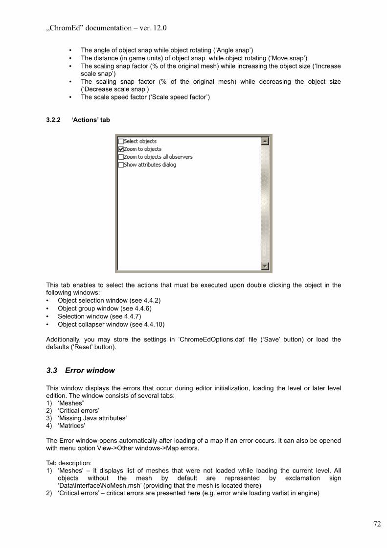
„ChromEd” documentation – ver. 12.0
• The angle of object snap while object rotating (‘Angle snap’)• The distance (in game units) of object snap while object rotating (‘Move snap’)• The scaling snap factor (% of the original mesh) while increasing the object size (‘Increase
scale snap’)• The scaling snap factor (% of the original mesh) while decreasing the object size
(‘Decrease scale snap’)• The scale speed factor (‘Scale speed factor’)
3.2.2 ‘Actions’ tab
This tab enables to select the actions that must be executed upon double clicking the object in the following windows:• Object selection window (see 4.4.2)• Object group window (see 4.4.6)• Selection window (see 4.4.7)• Object collapser window (see 4.4.10)
Additionally, you may store the settings in ‘ChromeEdOptions.dat’ file (‘Save’ button) or load the defaults (‘Reset’ button).
3.3 Error window
This window displays the errors that occur during editor initialization, loading the level or later level edition. The window consists of several tabs:1) ‘Meshes” 2) ‘Critical errors’3) ‘Missing Java attributes’4) ‘Matrices’
The Error window opens automatically after loading of a map if an error occurs. It can also be opened with menu option View->Other windows->Map errors.
Tab description:1) ‘Meshes’ – it displays list of meshes that were not loaded while loading the current level. All
objects without the mesh by default are represented by exclamation sign ‘Data\Interface\NoMesh.msh’ (providing that the mesh is located there)
2) ‘Critical errors’ – critical errors are presented here (e.g. error while loading varlist in engine)
72

„ChromEd” documentation – ver. 12.0
3) ‘Missing java attributes’ – the object list is displayed that were given a Java class attribute value but in currently parsed class the Java attributes are missing. Because of that the level saves may result in losing the previously set attributes. This situation may happen if you use old Java classes. Also the fact of Java class change (removing some attributes form it) is displayed on this tab
4) ‘Matrices’ – the objects list is displayed containing the objects which matrices didn’t pass the validation process while loading the level. This error may occur for many reasons, most of all they are very unpleasant, and should be corrected immediately (with use of ‘Matrix’ tab of the object attribute window)
3.4 Key shortcuts for 3D view
To access key shortcuts choose ‘Tools -> Shortcuts…’ from the main menu. Then the following window opens:
Using this window you may define the key shortcuts used to execute the respective actions. You may use the shortcuts while working on a viewport (that is when a 3D view is active)
Using ‘Filter’ combobox you may specify which actions are to be displayed on the list below (‘Shortcut list’ group). You may choose all actions to be displayed (as on the picture above) or specify the required plug-in which actions you want to be displayed or choose the editor actions.
The action short description and the respective key shortcut is presented on the list.
To change the key shortcut select the action on the list and specify the required shortcut in ‘Definition’ section. You may also change the shortcut by clicking ‘Press key’ button and then pressing the required key combination on the keyboard. Generally, on shortcut should be linked to one action.
The additional buttons on the right side enable to save the settings and to restore the defaults. During editor initialization the file ‘DefaultShortcuts.sdat’ is being loaded form the current work folder (providing it exists there)
73

„ChromEd” documentation – ver. 12.0
4 Existing plug-insIn this paragraph all existing plug-in are described (in alphabetical order). For each of them the basic information is given:• What the plug-in is used for• Plug-in idea• Dependence on other plug-ins (the plug-in list that may be loaded to make the plug-in fully
functional)• User interface description
4.1 Environment
4.1.1 PurposeThe ‘Environment’ plug-in is one of the basic plug-in critically needed to create a new level. The ‘Environment’ plug-in is used to specify and create the level data not connected with particular objects. Most of the initiating actions while creating new level are made by this plug-in but it is also used upon completing the level.The plug-in does not have its own form, the most important operations made with its use take place during the level object attribute change – most of the tabs concerning level object are the plug-in tabs (they are described in paragraph describing the object attribute setting – see 4.4.4).
The plug-in enables to:• Create the terrain (based on the bitmaps) with the defined size• Create the object grid (otherwise they cannot be placed on level)• Specify the settings for Sun and sky• Specify the for parameters• Specify the water (and ‘underwater’) parameters• Specify the global settings concerning rendering• Create the collision map for AI• Save the current heightmap to .TGA format file
4.1.2 Dependence on other plug-insThe ‘Environment’ plug-in does not depend on any other plug-in.
4.1.3 User interfacePlug-in menu ‘Environment’: 1) ‘AI collision generation’ – opens the AI collision map creation window2) ‘Get heightmap’ – opens the window for saving the heightmap / terrain normals map3) Other
i. ‘Renumerate objects’ – see description in 6.1.3.4
4.1.3.1 AI collision map creationClicking the proper plug-in toolbar button (see 6.1.3) opens the following window:
74

„ChromEd” documentation – ver. 12.0
First, you need to set:• File name of the output collision map (NOTE: clicking ‘Save filename’ saves the map under other
name without generating a new map). Clicking ‘OK’ starts the AI collision map generation process, clicking ‘Add to job list’ adds generation process to job list.
• Map cell size. Each cell represents a part of the terrain. It is a square with side specified by the cell size value (cm)
Then using the ‘Generate options’ section you need to specify what has to be concerned while generating the collision map (what is an obstacle). The following options are available:• ‘Boundary’ – the map boundaries• ‘Water’ – the player cannot walk into water• ‘Objects’ – all objects with collision flag on will make an obstacle.
NOTE: the collision map is generated only for the open terrains, NOT the building insides therefore they are concerned as an obstacle no matter if you can enter it or not.
• ‘Trees’ – trees with collision flag on will make the obstacle• ‘Terrain height’ – the terrain height difference will make and obstacle. To use this option you need
to enter the maximum terrain difference value specifying the cell height difference that makes the obstacle
You may choose any options set.
NOTE: besides the output map file consisting of the single option maps also the single option maps are saved as well as the RAW format files containing the uncompressed date easy to analyze (e.g. using Photoshop). They are saved in ‘PMGFiles’ subfolder of the main editor folder.
NOTE: The AI collision map should be created with all options on after the level is completed (the objects are located, the terrain shape is defined, etc.)
75

„ChromEd” documentation – ver. 12.0
4.1.3.2 Saving the heightmap/normals mapClicking the proper plug-in toolbar button (see 6.1.3) opens the following window:
Description:1) ‘Map type’ section enables to specify if you want to save the heightmap or the normals map. Same
of the following options are available only for the heightmap so this choice should be made at the beginning
2) ‘Map’ section – enables to specify the basic settings for the map generation. It is the path to output file and the map resolution. In case of the heightmap you also may save it in 16-bit resolution (by default it is saved in 24-bit resolution – TGA format)
3) ‘Start from pixel center’ checkbox – enables to specify if the bitmap covers the terrain completely (checked) or the terrain vertexes are in the middle of the bitmap boundary pixels (unchecked). In the second case each bitmap pixel covers bigger part of terrain than in first case.
4) ‘Relative heights’ checkbox – available only for the heightmaps – the bitmap describes the height in 8-bit resolution (256 values). The ‘Terrain’ tab ob the level object (see 4.4.4.17) you specify the way of height mapping that ‘0’ form bitmap reflects ‘0’ of height and the maximum bitmap value (255) reflects the maximum terrain height (255). All values are being interpolated. That way you may specify the terrain values that must reflect values of the bitmaps to make the terrain more detailed. But quite often it happens that the terrain cannot use the full height spectrum. In this moment some details are being lost. The ‘Relative heights’ checkbox enables to increase the details in way that the bitmap ‘0’ reflects the lowest terrain height and ‘255’ reflects the highest terrain height. That is the current values are being stored instead of the declared ones.
In case of saving the normals map each of the values is coded with different color:• X – red• Y – blue• Z - green
4.1.3.3 ‘Renumerate objects’
Clicking this option effects in re-numbering all objects located on the level that is to set a new ID for them. This option was added because of the errors of the previous editor versions when same ID objects were generated. Currently this option is mostly unused.
76

„ChromEd” documentation – ver. 12.0
4.2 Forester
4.2.1 Plug-in idea and purpose
The ‘Forester’ plug-in is used to place the vegetation. The vegetation system of engine divides it into trees and grass. Each level can have many tree and grass kinds specified – each plant belongs to the kind and change of the kind settings applies to all plants of that kind.
The ‘Forester’ plug-in enables to:• Create new and remove old tree and grass kinds• Add tree and grass to the level as well as remove them• Change of existing tree matrix• Automatic calculate the tree and grass lighting
Forester supports only static vegetation system. There exists also dynamic vegetation system, which:• Is able to plant grass at runtime. Grass is planted only in places that player see and removed from
the other places (to save memory).• Is able to place small (or even tiny) objects across the level. It works in the same way that
dynamic grass does, but it places meshes instead of billboards.
Dynamic system is based on scripts defining grass and object placement data. These scripts have to be set for every level using following level attributes:• ‘Grass params script’ – dynamic grass script• ‘Script containing tiny objects configuration’ – dynamic meshes script
4.2.1.1 Trees
Trees are plants that have own mesh to render and to collide with objects. Trees are visible from any side, each has full matrix and therefore each can be rotated and scaled.
4.2.1.2 Grass Grass is a plant rendered as a billboard. Due to that there are no collisions with grass and during the game they always face the player. The grass kind parameter is responsible for grass waving - simulating the movement caused by the wind blow.
There is one material for all kinds of grass. Kinds differ from one another with texture coordinates (material should use one and only one texture).
4.2.2 Description
4.2.2.1 Plug-in menu
Plug-in menu is titled ‘Forester’. It has following sub-menus:1) ‘Update to terrain‘ – updates positions of all vegetables to terrain height2) ‘Calculate lighting...’ – opens Tree lighting calculation window3) ‘Statistics’ – opens Statistics window4) ‘Reload tiny objects script’ – reloads script with tiny objects data5) ‘Dynamic grass’
a) ‘Reload density texture’ - reloads density texture path to which is stored in parameters scriptb) ‘Reload parameters script’ - reload parameters script path to which is stored in level attributes
6) ‘Import from module...’ – opens Import plants from module window7) ‘Predefined brushes’
a) ‘Import...’ – loads data stored in forester data script (.fscr file)b) ‘Export...’ – saves data to forester data script (.fscr file)
8) ‘List of types properties...’ - opens the properties window where you may specify what properties are being always displayed on the kind list
77

„ChromEd” documentation – ver. 12.0
4.2.2.2 Plug-in toolbar
1. 2.
Description:1) Shows / hides the plug-in form2) Turns on / off the single tree edit mode
4.2.2.3 Plug-in formMost of the plug-in functionalities is accessible by its form (it has been splitted due to its size):
Description:1) The list presents the existing tree and grass kinds. For each kind some of their properties are
presented – you may change them on the list (also you may open the special window to change the properties – then you may change all properties). The checkboxes located on the list specify if the kind is being used for the active tool – description below
2) – creates a new tree kind and opens the properties edit window
3) – creates a new grass kind and opens the properties edit window
4) – deletes the selected kind
5) – selects: all kinds of vegetables, all kinds of trees and all kinds of grass
respectively. If Shift is pressed while clicking this buttons deselecting takes place instead of selecting.
78

„ChromEd” documentation – ver. 12.0
6) ‘Brush attributes’ section – contains the parameters of the brush used while placing the vegetation
(they have different values for each tool). Those are: a) The bitmap specifies the brush shape. You may change it by clicking the bitmap.b) ‘Extents’ – specifies the area size that will be affected by single brush move.c) ‘Power’ – specifies the factor enabling to control the change speed made by the tool. For
Power = 0 the tool does not make any changes, for Power = 1 the changes are made with full tool strength. The changes are interpolated for all in-between values.
d) ‘Hardness’ – the parameter enabling to modify the changes from the bitmap. It does not influence the bitmap pixels with ‘0’ brightness (that is not making any changes). It is added to all other pixels (enabling to brighten up the bitmap)
e) ‘Mask bitmap’ – enables to define the bitmap mask that is mapped on all terrain and can disable the tool in some parts of the terrain. Checkbox enables using mask (of course to use it path must be specified too).
7) ‘Tools’ section – enables to choose the tool and to change its properties. Each tool works only for the kinds selected on the list (with checkboxes)
a) – turns on the tool adding the vegetation in an area pointed by the cursor and ‘Extent’
parameter of the brush
b) – turns on the tool adding the plant only in an area pointed by the cursor
c) – turns on the tool removing the plants (an area defined in the same way as ‘Add’ tool)
d) – turns on the tool updating height of plants to terrain
79
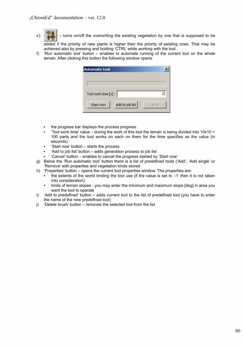
„ChromEd” documentation – ver. 12.0
e) – turns on/off the overwriting the existing vegetation by one that is supposed to be
added if the priority of new plants is higher then the priority of existing ones. That may be achieved also by pressing and holding ‘CTRL’ while working with the tool.
f) ‘Run automatic tool’ button – enables to automate running of the current tool on the whole terrain. After clicking this button the following window opens:
• the progress bar displays the process progress• ‘Tool work time’ value – during the work of this tool the terrain is being divided into 10x10 =
100 parts and the tool works on each on them for the time specifies as the value (in seconds)
• ‘Start now’ button – starts the process• ‘Add to job list’ button – adds generation process to job list• ‘Cancel’ button – enables to cancel the progress started by ‘Start now’
g) Below the ‘Run automatic tool’ button there is a list of predefined tools (‘Add’, ‘Add single’ or ‘Remove’ with properties and vegetation kinds stored
h) ‘Properties’ button – opens the current tool properties window. The properties are:• the extents of the world limiting the tool use (if the value is set to ‘-1’ then it is not taken
into consideration)• limits of terrain slopes - you may enter the minimum and maximum slope [deg] in area you
want the tool to operate i) ‘Add to predefined’ button – adds current tool to the list of predefined tool (you have to enter
the name of the new predefined tool)j) ‘Delete brush’ button – removes the selected tool from the list
80
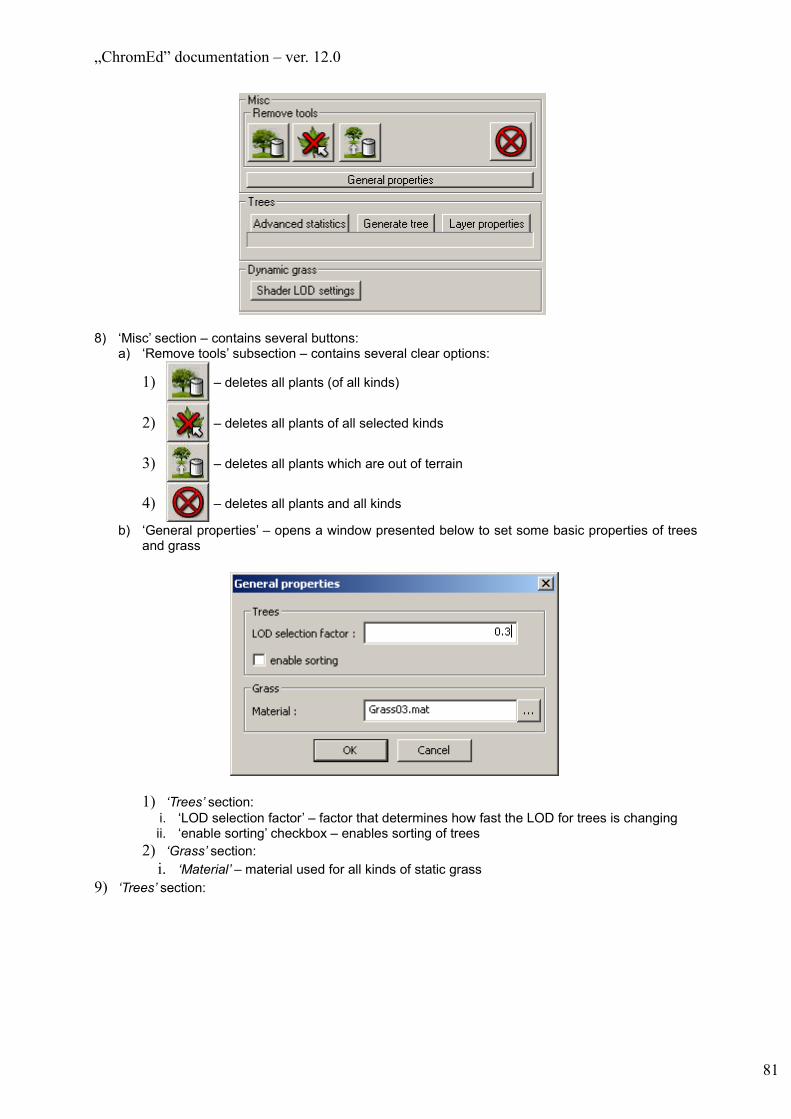
„ChromEd” documentation – ver. 12.0
8) ‘Misc’ section – contains several buttons:a) ‘Remove tools’ subsection – contains several clear options:
1) – deletes all plants (of all kinds)
2) – deletes all plants of all selected kinds
3) – deletes all plants which are out of terrain
4) – deletes all plants and all kinds
b) ‘General properties’ – opens a window presented below to set some basic properties of trees and grass
1) ‘Trees’ section:i. ‘LOD selection factor’ – factor that determines how fast the LOD for trees is changingii. ‘enable sorting’ checkbox – enables sorting of trees
2) ‘Grass’ section:i. ‘Material’ – material used for all kinds of static grass
9) ‘Trees’ section:
81

„ChromEd” documentation – ver. 12.0
a) ‘Advanced statistics’ button – opens window, that present advanced statistics of the trees.
Example of trees Advanced statistics window
b) ‘Generate tree’ button – rebuilds tree system internal data. Rebuild always takes place at level save. Using this button is recommended if a lot of changes has been made since last save operation.
c) ‘Layer properties’ button – opens Tree layer properties window that enables to set properties for all tree layers
10) ‘Dynamic grass’ section:1. ‘Shader LOD settings’ – opens ‘Dynamic grass shader LOD settings’ window where all
settings concerning LOD selection for all layers can be changed. When distance is less than ‘LOD 0’ LOD 0 is applied, when it is greater than ‘LOD 2’ LOD 3 is applied.
82
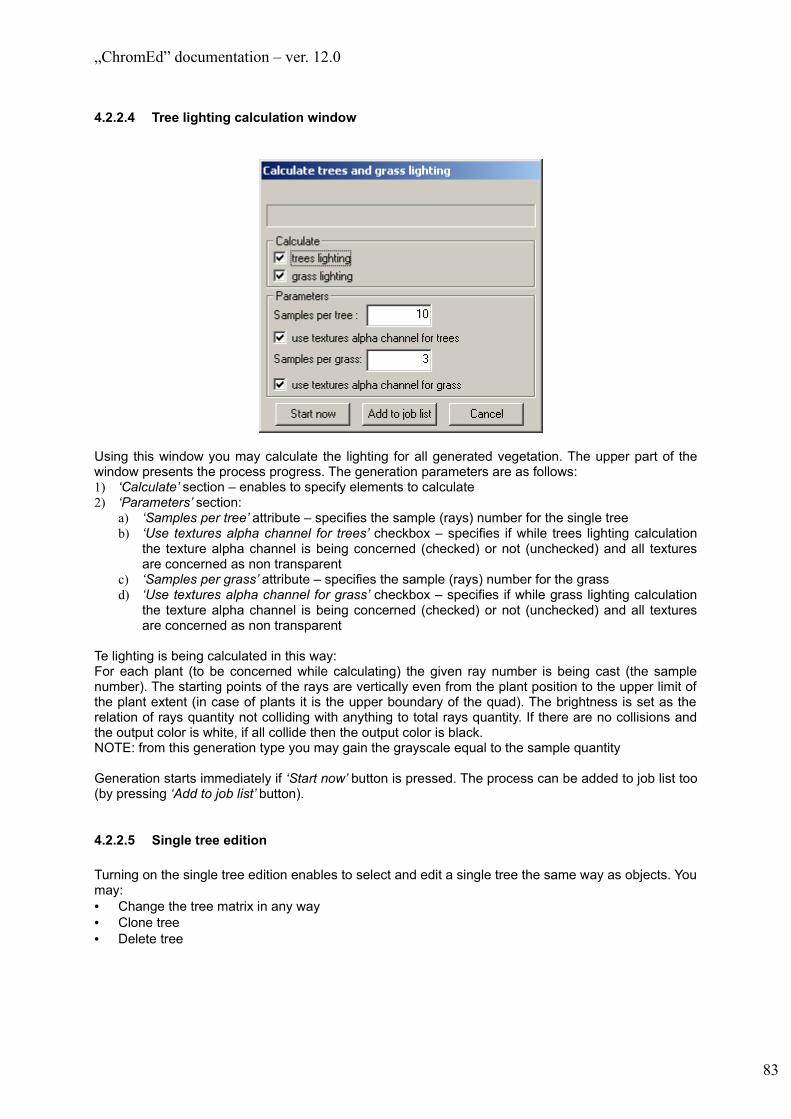
„ChromEd” documentation – ver. 12.0
4.2.2.4 Tree lighting calculation window
Using this window you may calculate the lighting for all generated vegetation. The upper part of the window presents the process progress. The generation parameters are as follows:1) ‘Calculate’ section – enables to specify elements to calculate2) ‘Parameters’ section:
a) ‘Samples per tree’ attribute – specifies the sample (rays) number for the single treeb) ‘Use textures alpha channel for trees’ checkbox – specifies if while trees lighting calculation
the texture alpha channel is being concerned (checked) or not (unchecked) and all textures are concerned as non transparent
c) ‘Samples per grass’ attribute – specifies the sample (rays) number for the grassd) ‘Use textures alpha channel for grass’ checkbox – specifies if while grass lighting calculation
the texture alpha channel is being concerned (checked) or not (unchecked) and all textures are concerned as non transparent
Te lighting is being calculated in this way:For each plant (to be concerned while calculating) the given ray number is being cast (the sample number). The starting points of the rays are vertically even from the plant position to the upper limit of the plant extent (in case of plants it is the upper boundary of the quad). The brightness is set as the relation of rays quantity not colliding with anything to total rays quantity. If there are no collisions and the output color is white, if all collide then the output color is black.NOTE: from this generation type you may gain the grayscale equal to the sample quantity
Generation starts immediately if ‘Start now’ button is pressed. The process can be added to job list too (by pressing ‘Add to job list’ button).
4.2.2.5 Single tree edition
Turning on the single tree edition enables to select and edit a single tree the same way as objects. You may:• Change the tree matrix in any way• Clone tree• Delete tree
83

„ChromEd” documentation – ver. 12.0
4.3 LightmapsEd
4.3.1 Purpose
The ‘LightmapsEd’ plug-in is used for lightmap generation for terrain and objects.
NOTE: the lightmap generation process takes a considerable amount of time. It is advised to locate the objects in their final location before generation of the lightmap (both terrain and objects). It is possible to generate the lightmap for single object. However the object transformation may cause the need to re-generate the lightmaps for other objects and terrain. The decision, which lightmaps are to be regenerated, is left to the user.
There is a possibility to speed-up lightmap generation by using several computers to do so. That process is described in 6.3.3.5.
4.3.2 Dependence on other plug-ins‘LightmapsEd’ plug-in depends on ‘Mesh Browser’ plug-in.
4.3.3 User interface
The plug-in toolbar has only one icon which opens plug-in form:
4.3.4 LightmapsEd form
Due to its size the form is divided for the purpose of describing it.
1) ‘Generate lightmaps’ section:a) ‘preview’ – enable it to generate only preview of lightmaps (e.g. shadows are not generated at
all).b) ‘raytrace in both directions’ – means that while rendering a new lightmap the rays will be
traced in both directions (from and to the light source). It is possible to specify the way of raytracing as one way (from the light source to object) or both ways (also from the object to the light source). The both way raytracing is slower but necessary in some cases when the collisions occurs on one side of the triangle (if the ray traces the triangle ‘from the back’ the there is no collision). Terrain shape when this matters: deep hole (e.g. mine shaft) and the sun low on the horizon – the hole bottom will be lighted only by one way tracing. The both way tracing will handle the problem.
c) ‘raytrace trees’ – enables / disables tracing trees while generating lightmaps both for objects and terrain
84

„ChromEd” documentation – ver. 12.0
d) ‘raytrace trees (ambient occlusion)’ – as ‘raytrace trees’ but only for ambient occlusion calculations
e) ‘Generate for selected objects’ section – used for selected object lightmap generationi) ‘Generate’ – starts the generation process immediately – the object lightmap generation
window opensii) ‘Add to job list’ – lightmap generation process is added to job list. NOTE: generation will
be processed for objects selected at the moment this button is pressed.f) ‘Generate for all objects’ section - used to generate the lightmaps for all level objects that have
the proper flag seti) ‘Generate all’ – starts the generation process immediately – the object lightmap generation
window opensii) ‘Add to job list’ – lightmap generation process is added to job list
g) ‘Override parameters’ – opens a window (see 6.3.4.2) that enables to set override parameters. These are parameters, that have influence on lightmap generation. They are not saved on map. Their only purpose is to make prototyping easier.
h) ‘enable distributed generation’ checkbox – see 6.3.4.5
i) ‘Default parameters for objects’ – opens a window, that enable to set lightmap generation parameters, that apply to all objects, which have flag ‘use default parameters’ set (see 4.4.6.7.1).
j) ‘Compile lightmaps’ section:i) ‘Format’ – format of result lightmap imagesii) ‘Compile for selected objects’ subsection – used to compile lightmaps for currently
selected objects(1) ‘Compile’ – starts compilation process immediately(2) ‘Add to job list’ – adds compilation process to job list. NOTE: compilation will be
processed for objects selected at the moment this button is pressed.iii) ‘Compile for all objects’ – used to compile lightmaps for all objects on level
(1) ‘Compile all’ – starts compilation process immediately(2) ‘Add to job list’ – adds compilation process to job list
k) ‘Delete lightmaps for selected objects’ – deletes lightmap for selected objects. Object states are automatically refreshed to reflect this change.
l) ‘Delete lightmaps for all objects’ - deletes lightmap for all objects. Object states are automatically refreshed to reflect this change.
m) ‘Distributed generation’ subsection – described in 6.3.4.5
85

„ChromEd” documentation – ver. 12.0
4.3.4.1 Terrain lightmap generation
To start the terrain lighting generation process use ‘Lighting’ tab of the level object attributes window (see 4.4.4.8.2).
4.3.4.2 Override parameters
There are two kinds of settings in this window:1) Maximum allowed values (‘Max samples per pixel’, ‘Max texels per meter’, ‘Max rays per texel’
and ‘Max ray length’ ) – they define boundary values for some settings. If a per-object setting is higher than the number entered in this window maximum allowed value is taken for purpose of the generation.
2) Flags (all checkboxes) – they define if a particular flag can be set. Disabling a checkbox means that a flag is not allowed to be set for purpose of the generation.
4.3.4.3 Generation process for objects
Upon starting the object generation process (both by clicking ‘Generate’ and ‘Generate for all objects’) the dialogue window opens that remains opened during the whole process and enables to stop the process. The window is presented on the following picture:
86

„ChromEd” documentation – ver. 12.0
• ‘Cancel’ button enables to stop the generation process• ‘Current objects’ sections – displays the current object name and the progress bar presents the
generation process progress for this object only• ‘All objects’ section – the progress bar displays the generation process progress for all objects set
to generate the lightmaps for
4.3.4.4 Setting the light source properties
To set the light source properties use ‘Light’ tab of the object attribute window (see 4.4.4.7).
4.3.4.5 Distributed generation of lightmaps for objects
There are following phases of a process of distributed generation of lightmaps:1) Preparation
a) Map folder with the newest version of map must be copied to all the computers that are supposed to be used in the generation
b) On the server working folder should be created and shared to all users (read and write rights are required). In facts this folder can be placed on any computer in the network but it is recommended to be on the server machine because of performance reasons.
c) Run ChromEd, load map on all the computersd) Configuration of server and clients:
i) In plug-in LightmapsEd form path to working folder must be filled. Assuming that folder is on the server workstation proper formats of paths are as follow:(1) On client machines: \\name_of_computer\name_of_folder(2) On the server machine it needs to be full path to the folder
ii) Set ‘enable distributed generation’ flag on the server machine (plug-in LightmapsEd form)2) Generation
a) Select all objects you want lightmaps generated for and press ‘Generate’ button.b) Press ‘Start client’ button on all client machines
It is allowed to start clients before server, but clients stops working if it does not get a task to do in a 10s.
3) Copying resultsAll result files are on clients in subfolders ‘lm’ of the map folder. It is necessary to copy them to destination location on the server.
4.4 Mesh Browser
The only plug-in located not in DLL format file named MeshBrowser (as all plug-in) but in Control.dll file.
4.4.1 Purpose
The ‘Mesh Browser’ plug-in is one of the most important ChromeEd plug-ins. It is responsible for adding new objects to level, positioning them, selecting them in viewport and positioning the observer in active viewport. It also has other functions like:• Creating the object hierarchy (not to confuse with object selections described in 4.4.7)• Copying objects located on the level• Snapping the objects• Screenshot creation (direct viewport screenshots and satellite photos)
4.4.2 Dependence on other plug-ins
The ‘Mesh Browser’ plug-in does not depend on other plug-ins.
87

„ChromEd” documentation – ver. 12.0
4.4.3 Transformations in viewport
The ‘Mesh Browser’ uses the viewport the most time. Practically all operations of object and observer positioning are made by this plug-in (though to position the object you may also use the ‘Matrix’ tab of the object attribute window – see 4.4.4.9).
The ‘Mesh Browser’ plug-in is usually in specified work mode (to recognize the current work mode see the Mesh Browser button state on the toolbar or see the cursor shape). To choose the work mode click the button on the editor toolbar (see 6.4.4).
4.4.3.1 Views
One of the plug-in features is specifying the view. This plug-in adds couple of elements concerning the view type to the viewport context menu:• ‘Perspective’ – Perspective view (3D)• ‘User’ – orthogonal view• ‘Front’, ‘Back’, ‘Top’, ‘Bottom’, ‘Left’ and ‘Right’ – predefined orthogonal views – the camera turns
into orthogonal view and directs according to the selected option (e.g. ‘Top’ view – the camera is directed top down). Any camera rotation in such case switches to ‘User’ view
4.4.3.2 Observer (camera) positioning
You may position the observer (camera) by using:1) Direction keys – they move camera up, down and to sides2) Mouse – depending on the work mode you may (with left mouse button pressed):
a) move the camera in view plane – ‘Pan Camera’ modeb) rotate the camera (change the view angle without changing the location) – ‘Rotate Camera’
modec) change the scale (orthogonal view) or move the camera along the view vector (perspective
view – ‘Zoom camera’ mode. Only the vertical mouse movement is important.d) Rotate the camera around the selection center in specified distance (in case of single object
the center is the object, in case of multiselection the center is the center of the selection). In this mode the camera moves on the sphere which center is the center of the selection. The camera is directed all the time to the center of selection. The only limitation is in the poles of that sphere not allowing to pass it and to look upside down – ‘Arc – rotate camera’ mode
e) Rotate the camera around the screen center – similar mode to the previous mode but here the camera is being rotated around the screen center. You may turn on/off displaying the center of the rotation using menu Control->Other->Camera orbit point command.
3) Mouse – with middle mouse button pressed you automatically switch to ‘Pan Camera’ mode4) Mouse – with right mouse button pressed you automatically switch to ‘Rotate Camera’ mode
unless there is a context menu to be displayed for an object pointed by the mouse cursor5) Mouse wheel – switches to ‘Zoom Camera’ mode6) Pressing ‘x’ key – it results in displaying the current selection in active viewport the way the whole
selection is visible (the viewport MUST be active one). Pressing ‘SHIFT-x’ displays the current selection in all viewports.
7) Using the ‘Fly/Walk’ mode – to enter this mode you have to use the context menu for viewport title bar (Observers...->Enter ghost mode) or press ‘G’ key. You may exit this mode ONLY by pressing ‘G’ key again. In this mode the mouse cursor is invisible. The movement is disabled if the observer is out of the terrain extent while turning this mode on. If you press and hold ‘SHIFT’ key then the movement speed is multiplied by the ‘Speed Factor’ value in ‘Observer Mode Properties’ window (6.4.4).
8) ‘1-9’ alphanumerical keys – moves the observer on the constant (current) height. The camera orientation remain unchanged.
9) ‘2’ and ‘8’ alphanumerical keys with ‘CTRL’ key pressed – works as ‘Zoom Camera’ mode10) ‘4’ and ‘6’ alphanumerical keys with ‘CTRL’ key pressed – rotates the camera around the screen
center on the same height (Y axis)
88

„ChromEd” documentation – ver. 12.0
11) ‘7’ and ‘9’ alphanumerical keys with ‘CTRL’ key pressed –rotates the camera in XZ plane. The camera position remain unchanged.
NOTE: all keys are the default keys and can be re-defined (see 5.4). It concerns all keys described in this document.
4.4.3.3 Object interaction
The object interaction is possible by the left mouse button and the proper plug-in work mode:• ‘Select Objects’ mode – it enables object selection (multiselection is allowed). To select the object
simply click it. To add (or remove) the object to the selected objects list click the object while holding ‘CTRL’ key. Also you may select the object by defining the rectangle (extent) in viewport – it works the same way as defining the water extent (see 4.4.4.18) but here you select all not hidden objects in the extent. To deselect the selected object you may use ‘ALT’ key. Clicking the selected object while holding ‘ALT key pressed deselects the object. While holding ‘ALT’ key pressed you may also choose extent to deselect.
• ‘Select Lock’ mode – disables the selection change for objects. To turn on/off this mode use the button on the toolbar or press ‘SPACE’
• ‘Attach Objects’ mode – enables to connect objects in hierarchy (of ControlObjects). All transformations to the object are also made on all object located below in hierarchy (on three where the given object makes the tree root). In case the object and the object from the subtree is selected only one transformation is being done.
• ‘Move Objects’ mode – enables to change the object position• ‘Rotate Object’ mode – enables to rotate the objects• ‘Scale Objects’ mode – enables to scale the objects. Using the viewport you may scale the object
in three dimensions at the same time with the same scaling factor. To scale the object in only required dimensions use the ‘Matrix’ tab in Object attributes window (see 4.4.4.9)
In case of ‘Move Objects’ and ‘Rotate Objects’ modes you have to choose the axis/plane for transformation. You may select it using the menu (Control->Other->Directions and then desired axis/plane) or using the Gizmo (by ‘holding’ the axes of the selected object).
Object scaling with the Gizmo is possible only after tuning on the Gizmo visualization responsible for scaling (by default it is in invisible). You may turn it on using menu (View->Gizmo->Scale gizmo) or by they key (not defined by default). The scaling Gizmo consists of many elements (e.g. side, extent vertex). To scale the objects you have to ‘pull’ one of those elements (the opposite element remain unchanged.
NOTE: the operation mode set by the Gizmo overrides the current mode. In other words if the scaling mode is on and you ‘hold’ the Gizmo axis responsible for movement then the selected objects are moved.
In case of all transformation the axis coordination mode is important. You may choose the coordination on the toolbar (the toolbar displays the current selection – see 6.4.4).In ‘World’ axis coordination mode the axis are identical with world axes and in case of multiselection the ‘point zero’ for axes is in the center of the selection.In ‘Local’ axis coordination mode the axes are directed according to the current object rotation (separately for each object). The ‘point zero’ for axes is different for each object and connected with its position. For each object the separate Gizmo is displayed presenting the local axes coordination mode. However all transformations are always made for all objects around selected axis/plane (most probably it will be different for each object) no matter which Gizmo is used for that transformation.
If you move the object and the ‘Snap Objects’ mode is on (you may turn on/off this mode using menu Control->Snap objects command or by pressing ‘S’ key) then the objects will be joined with use of portals (see 4.4.4.4) or hooks if the distance of portals/hooks is less then the value set while initializing hr mode (only by the button on the toolbar). The portals are automatically snapped with hooks. The hook is a MeshElement having ‘hook’ string in its name.NOTE: The portal is not being automatically created!
89
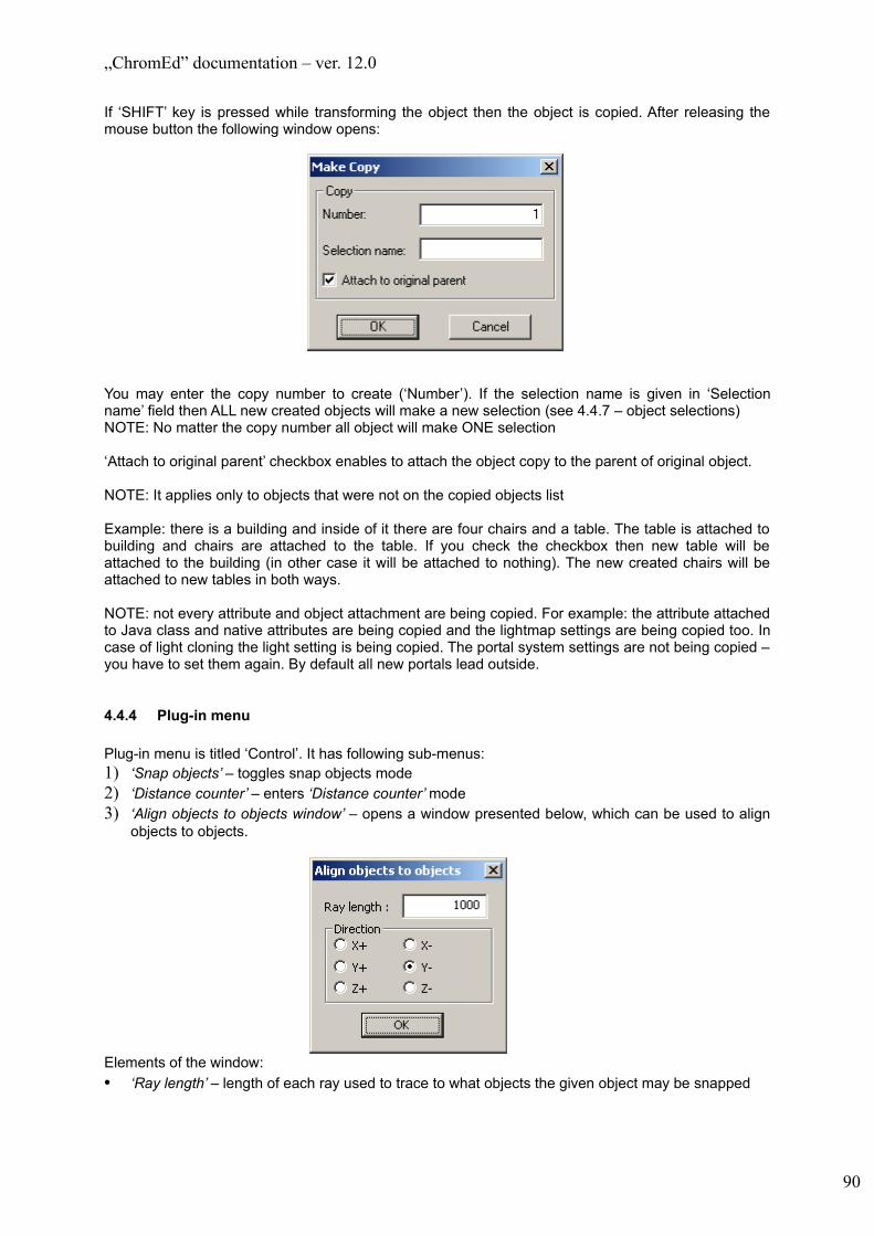
„ChromEd” documentation – ver. 12.0
If ‘SHIFT’ key is pressed while transforming the object then the object is copied. After releasing the mouse button the following window opens:
You may enter the copy number to create (‘Number’). If the selection name is given in ‘Selection name’ field then ALL new created objects will make a new selection (see 4.4.7 – object selections)NOTE: No matter the copy number all object will make ONE selection
‘Attach to original parent’ checkbox enables to attach the object copy to the parent of original object.
NOTE: It applies only to objects that were not on the copied objects list
Example: there is a building and inside of it there are four chairs and a table. The table is attached to building and chairs are attached to the table. If you check the checkbox then new table will be attached to the building (in other case it will be attached to nothing). The new created chairs will be attached to new tables in both ways.
NOTE: not every attribute and object attachment are being copied. For example: the attribute attached to Java class and native attributes are being copied and the lightmap settings are being copied too. In case of light cloning the light setting is being copied. The portal system settings are not being copied – you have to set them again. By default all new portals lead outside.
4.4.4 Plug-in menu
Plug-in menu is titled ‘Control’. It has following sub-menus:1) ‘Snap objects’ – toggles snap objects mode2) ‘Distance counter’ – enters ‘Distance counter’ mode3) ‘Align objects to objects window’ – opens a window presented below, which can be used to align
objects to objects.
Elements of the window:• ‘Ray length’ – length of each ray used to trace to what objects the given object may be snapped
90

„ChromEd” documentation – ver. 12.0
• ‘Direction’ subsection – there are 6 checkboxes each for one direction. Both ‘World’ and ‘Local’ coordination modes can be used but one must has in mind that in case ‘Local’ is used for multiselection, objects might go in different directions.
• ‘OK’ button – pressing it processes alignment
NOTE: The move vectors are defined for all objects before they change their positionNOTE: For proper snapping the objects should have ‘Per Face’ collision type set (and of course collision map generated)
4) ‘Other’a) ‘Add replay cameras’ – disabledb) ‘Directions’ – submenu that contains axes and planes used by transformationsc) ‘Camera orbit point’ – toggles rendering of camera orbit point
4.4.5 Plug-in toolbar and actions executed from the toolbar
NOTE concerning the work mode change:• The buttons for changing the work mode are located on all toolbars – they are described below• Only one work mode can be active – activating new mode cancels the current work mode• If the editor is in any mode then it is presented by the proper button state (on the toolbar or in the
main window). It also concerns situation when the mode is activated by the key. Additionally, the change of work mode is presented by change of cursor shape.
The ‘Mesh Browser’ plug-in has three toolbars:
4.4.5.1 Main toolbar
1. 2. 3. 4. 5. 6. 7. 8. 9.
Toolbar elements:1) Button activating/deactivating the ‘Mesh Browser’ plug-in2) ‘Select Objects’ mode3) Turns on/off the selection lock - ‘Select Lock’4) ‘Move Objects’ mode5) ‘Rotate Objects’ mode6) ‘Scale Objects’ mode7) Axis coordination mode (‘World’/’Local’)8) ‘Attach Objects’ mode9) ‘Detach Objects’ mode – detaching the selected object from their parents in hierarchy
Actions / setting change available through this toolbar:1) Turn on ‘Fly/Walk’ mode – if activated by the toolbar you may set the mode preferences (if you
activate the mode my ‘G’ key then it has the previous properties). To change the mode preferences use the following dialogue:
91

„ChromEd” documentation – ver. 12.0
a) In ‘Move properties’ section you may specify the step length forward/back (‘Move ratio’) and left/right (‘Pan ratio’) and the step multiple factor (with ‘SHIFT’ key pressed). It concerns both ‘Fly’ and ‘Walk’ modes
b) ‘Constant Height Mode’ section concerns ‘Walk’ mode. You may specify the height that camera will be over the terrain and if mode is one (if not then ‘Fly’ mode is on)
2) Turn on ‘Snap Object’ mode – similar to ‘Fly/Walk’ mode activating by the toolbar opens the dialogue enabling to set the snapping distance:
4.4.5.2 Scene toolbar
1. 2. 3. 4. 5. 6.
Toolbar elements:1) ‘Pan camera’ mode2) ‘Rotate camera’ mode3) ‘Zoom camera’ mode4) ‘Arc – rotate camera’ mode5) ‘Arc – rotate camera around middle of screen’ mode6) ‘Distance counter’ – measures the distance between two points on the level (terrain or object). The
distance is being updated all the time and the result is being displayed in the mode name field on the status bar (see 4.3.2)
4.4.5.3 Align toolbar
1. 2. 3. 4. Toolbar elements:1) ‘Align to terrain’ – selected objects are moved down this way that their pivot point is on the terrain
surface2) ‘Place objects’ mode – pressing this button activates that mode where you may specify the new
object position (the center of selection in case of multiselection) on the ground or other object
92

„ChromEd” documentation – ver. 12.0
3) ‘Place objects to terrain’ – as above but in this case you may put objects only on the ground (all objects are concerned as ‘transparent’ and there are no collisions with them)
4) ‘Place objects to observer position’ – moves the selected objects to observer position
93

„ChromEd” documentation – ver. 12.0
4.4.6 Plug-in main widow description
The picture was resized duo to its large size:
This window enables to add new object or object selection to the level.The tabs are used to define the adding properties. The picture above presents the ‘Settings’ tab, all other tabs are presented below:
1) ‘Drop’ tab:
94

„ChromEd” documentation – ver. 12.0
2) ‘Rand Rotate’ tab:
3) ‘Rand Scale’ tab:
Plug-in main window description:1) ‘Place Object’ section. There are two buttons there available only if all required data for adding the
object are given:a) ‘Put object’ / ‘Add object’ – the name of the button depends on the added object type. It is
used to add a single object or object selection to the level. The way of adding depends on its name• ‘Put Object’ – you add object inheriting from ControlObject or object selection. You need to
specify in viewport the position for the object (object selection)• ‘Add Object’ – you add object inheriting from GameObject that is not located somewhere
in specific in object grid. Because the object has no matrix it is being added at once upon clicking the button. Also the object attribute window opens to edit the object properties.
b) ‘Put selection at original pos’ button – available only if you add the object selection. It enables to automatic placement of the object selection as it was while exporting it from the original level
The placement properties are set on the different tabs:1) ‘Settings’ tab – main settings concerning the adding object
a) ‘Type’ combobox specifies the object type. It is being specifies by the ‘EditorStart.ini’ file (see 3.4.2.4). The following types are:• ‘Normal’ – it concerns both adding a single MeshObject and object selection. Only in this
case the tree for choosing the mesh is available and the list of last added meshes 9at the bottom of the window)
• Any abstract Java class name – ‘Put Object’ button becomes disabled and you have to select a Java class inheriting from that abstract class to enable this button. You cannot choose mesh – it is set by the editor.
95

„ChromEd” documentation – ver. 12.0
• Any other option – object may be added by ‘Put object’ / ‘Add object’ button. The class and mesh are chosen by the editor
b) ‘Mesh’ field – displays the mesh of the added object. Not in all cases the filed is filled. Using this field you cannot choose or change the mesh (other elements are used for that)
c) ‘Class’ field – displays the Java class of the added object. In some cases (see above) you may or even you must change he object class. To do that use the browsing button ‘…’ located right to that field.
2) ‘Drop’ tab – enables to specify the way of adding the object to the level:a) Placing the object in front of the observer (in a very close distance) – ‘Place in front of
observer’b) Dropping the object on the terrain surface (‘Drop to terrain’). The object is being put on the
terrain in the place pointed by the mouse cursor. If there is no collision with the terrain at the pointed location then the object is being put in front of the observer
c) Dropping the object on other objects (‘Drop to objects’). It works similarly to ‘Drop to terrain’ but while placing the object also the collisions to other objects are being checked
d) Dropping the objects on objects with distance (‘Drop to objects by box’). Works similarly to ‘Drop to objects’ but at the end the added object is replaced in the given axis in way that its extent is not in the placing point
e) Dropping with constraints (‘Drop with constraints’). Object is being dropped along the vector that begins in the observer position and the direction is set by the left mouse click. You may enter the constraints concerning the destination. The vector is being modified to match the constraints and then the object position is defined
Example 1: entering three constraints results in not placing the objects no matter the destination wasExample 2: entering one constraint results in dropping the object on the given plane and the vector is set according to mouse click
f) Dropping with physics (‘Drop with physics’). Object is being dropped as in ‘Drop to objects’ mode but right after object is created physics impulse is applied to it.
NOTE: no matter the add mode when you specify the add point (by left clicking) and you hold ‘CTRL” key pressed then they Y axis of the object local coordination mode is identical with normal of the adding place (terrain or object)
3) ‘Rand rotate’ tab – enables adding the object and its random rotation in given axis/axes4) ‘Rand scale’ tab – enables adding the object and its scaling in given scaling range in any axes. In
case the object is to be scaled with the same factor in all axes you need to check ‘All the same (as X)’ checkbox. Then only one parameter is being randomized (X axis) and the result is set to all axes
5) Folder tree and ‘Last used meshed’ section – available only if ‘Normal’ type is selected in ‘Type’ combobox (‘Settings’ tab). Using these elements you may choose the mesh for the adding object. Not selecting the mesh makes the adding not possible.
NOTE 1: the mesh defines the initial object nameNOTE 2: choosing .eds format file you decide to add the object selection (see 4.4.7)
The tree may have several tabs. Each of then specifies different folder tree root that you search in (generally all data must be located in subfolder ‘data’ of the folder that contains the editor executables). There is always ‘data’ tab which contains all folders that might contain the data. Other tabs might be created with use of the context menu for any not empty folder. Then the following window opens:
96

„ChromEd” documentation – ver. 12.0
The upper part of this window presents the absolute path for the created tab. The ‘Tab name’ field specifies the tab name.
Mask can be used to filter files presented in the tree control. When it is empty trees contain folders and files (*.msh, *.3da and *.eds files). When mask is not empty trees work as lists. They contain only files (no matter from which subfolders of the tab root folder they are) that match the mask. A mask is defined for each tab independently.
To choose the mesh for the adding object you also may use the ‘Last used meshes’ list containing the last used meshes.
4.5 Films
4.5.1 Purpose
The ‘Films’ plug-in is used for making the films that later on may be played during the game as well as directing the cut-scenes (they differ by the fact of defined camera – described further in this paragraph). For both cases the term ‘film’ is being used in this document if not mentioned differently. You may create many films for one level.
The film may use all objects located on level with exception of objects in groups and editor helpers. Additionally, for the give film purpose you may create new objects to use in that film. During the film play all objects not existing on the level are presented as virtual objects. Additionally, in films you may use the dynamic lights created only for that film.
NOTE: There are two kinds of dynamic lights used in films. The names are historically given and do not correspond to the current light purposes:• GL lights – light only the vertexes• Dynamic lights – ‘regular’ lightsThe object light depends on the object materials.In this document both names are used because of the user interface.
From the editor point of view the film consists of several actors (objects in film). Each actor has the proper tracks set defining all actions connected to that actor during the film. Additionally, the tracks exist also for level objects, all lights used in the film and cameras used in the movie. The track set is different, depending on what they concern – described below. On each track you may set the keys enabling to specify the moment to execute the action. Each track can have only keys of one kind (the same as the track).
During the film creation the level object tracks are automatically added and the Sun track is specified (providing the Sun is placed on the level – the GL light)There are following track sets:1) For level object:
a) Cameras – any given numberb) Soundsc) Java methodsd) Flags
97

„ChromEd” documentation – ver. 12.0
2) For objects:a) Positionb) Rotationc) Scaled) Animation – there might be many animation tracks – described belowe) Speechf) MTSpeechg) Soundsh) Java methodsi) Flagsj) Mimicsk) Eye controller
3) For GL lights:a) Positionb) Colorc) Flags
4) For dynamic lights:a) Positionb) Rotationc) Scaled) Colore) Flags
5) For cameras:a) Camera positionb) Camera target positionc) FOVd) Rotation around the direction axis (Roll)
The dynamic lights and cameras may be added to the film with the context menu (described further in this document). There may be many lights and cameras defined for one film.
Use of cameras depends on the game. It concerns those film moments when no camera is defined (for example the view from players eyes).
Description of the track kinds and track keys:1. Camera tracks – they may be placed only on level object track. There may be many camera
tracks. Each track has the priority defining which camera key is being concerned in the given second of the film – the film is always played for the camera on the track with the lowest number and the update is being done to all cameras, no matter if used or not.a) Camera key parameters:
• Name of the camera used by the key (‘Camera’) – you may choose one from the cameras defined for the film
• Camera delay time (‘Delay time’) – the parameter mainly for use of cameras defined by no longer used mechanisms. It enables to set the delay between the current film second (the second that camera key is in) and the second on the track of the camera. For example:
Value ‘0’ means that for film 6th second you take camera track 6th secondValue’3’ means that for film 6th second you take 3rd second
No keys can be at the same position on the track – that’s why there are many tracks defined to execute several keys at the same time.
2. Position, rotation and scale tracks (for objects) – in each key the proper vector is given used for specifying the object matrix modifications. Depending on whether the object is attached in film hierarchy to another object or not you enter the vectors in ‘World’ axis coordination mode (not attached) or in ‘Local’ axis coordination mode (attached). Additionally you specify the method of
98

„ChromEd” documentation – ver. 12.0
changes from the previous key and to the next key. The options are described further in this document.
3. Sounds tracks – the keys placed on these tracks enable to play the sounds (.wav format files). Depending on whether the sound is played for object or level object you may define different parameters
a) Common parameters:• .wav (or .ogg) format file path with the sound to play (‘Wav file path’)• flag specifying whether the sound is to be played just once or will be repeated (‘Looped’)
b) Key parameters on the level object track• vector of world position specifying the sound play location
c) Key parameters on the object track• flag specifying if the sound follows the moving object. If not set then the sound is being
played at the current object location and will remain there until it ends (‘Follow object’)
4. Speech tracks – the keys placed on those tracks use for speech play for the given object which is not only playing the proper sound but also proper animations for the character lips that the key is being played. The keys on such tracks cannot be at the same place.Key parameters:a) .wav (or .ogg) format file path with the sound to play. According to the sound file name the
phonem file is specified which will be used to visualize the lips moves of the speaking character. The phonem file path is specified in this way: ‘data/sounds/others/sound_file_name.phn’
b) text that will be displayed as the caption – before the display this caption is processed by the localizing string system which is described in another document
NOTE: This is obsolete track type - in general MTSpeech tracks should be used
5. MTSpeech tracks – they have almost identical meaning to Speech keys but animations of lips is based on morph targets instead of bones. Key parameters:a) Path to a sound file (as in case of speech keys)b) Text of a caption (as in case of speech keys)c) Name of a mesh element that determine position of source of soundd) Sound volumee) Sound range factor
6. Animation tracks – they enable to play the object animation. Initially for each object only one animation track is defined (‘Animation keys’). All the key animations without defined MeshElement are placed on this track – that is the root starting the animation play (the animation is played for all MeshElements located in the subtree root. When you define the root the key is being moved to the new track (named after the root). If the track doesn’t exists it is being created.Key parameters:a) ‘Mesh element’ – the tree root for animation to playb) Animation sequence name to be played (‘Animation sequence’)c) Frequency (‘Frequency’)d) Loop quantity (‘Repeats’)e) Initial frame for this sequence (‘0’ means start of any sequence from the first frame and not
playing the first animation frame from all animation frames of the given object)
The keys on these track may be located at the same place which effects in playing many animations at the same time.
7. Java methods tracks – the keys on that track enable to activate the no-parameter Java method. Key parameters:a) ‘Name’ – the name of Java method to activate – you must make sure that the method may be
activated for the given object classb) ‘Call after stop movie’ – specifies if the method is activated even of the film play is interrupted.
There are two ways of stopping the movie in the game: the first results in immediate play stop and the second additionally calculates the tracks to the film end (it concerns e.g. object matrix
99

„ChromEd” documentation – ver. 12.0
tracks and Java method tracks. In case of the second way the value of this key parameter matters
8. Color tracks – you may set the color by using the standard color selection window
9. Flags tracks – the flag track set is different depending on what they concern (level object, object or light)a) Level object flags:
• ‘Portal system active’ – turns on/of the portal systemb) Light (both kinds) flags:
• ‘Enable’ – enables the given lightc) Object flags:
• ‘Object invisible’ – the object is excluded from rendering• ‘Cast shadows’ – the object casts the shadows (both blobs and shadow maps)• ‘Receive shadows’ – the object receives shadow (for blobs only, you cannot turn this
option for shadow maps)• ‘Use object LODs’ – specifies if LODs are used for this object
10. Camera position and camera target position tracks – for both kinds the same key settings apply:a) position vector (in case the position / target position is attached to any object – MeshElement
– than those positions are presented in local axis coordination mode. While changing the attachment the vector is being changed
b) ways of changing to next/previous position (the same as position, rotation and scale vector change – described below)‘Object ID’ – object ID to which the position/target position is attached to. You may change the object by entering the new ID and changing the parameter selection (to confirm the change re-calculate the vector) or by using the active viewport context menu. If you selected this parameter then the context menu opens over the object you want to attach the camera to e.g.: Link camera to object MetalCrateA02(34685)Choosing this option attaches the camera to object
c) ‘Mesh element name’ – name of MeshElement that the position/ target position is attached to. You may enter the name or use the browsing button ‘…’
11. FOV tracks – enables to change the camera FOV. You may set:a) FOV value in that secondb) ways of changing to next/previous key
12. Roll tracks – enables to set the camera rotation in camera direction axis (that is facing the target)a) roll in degreesb) ways of changing to next/previous key
13. Mimic tracks – enables to setup expression of the face of the object. They use .fed files where all mimic data are stored. For each object there are 3 mimic tracks. In such a way mimic keys can overlap (it is impossible to do with only 1 track).Key parameters:a) Name of mimic to morphb) Fade in time – in [s]c) Fade out time – in [s]d) Morph target delta multiplier - must be in [0; 1]
14. Eye controller tracks – enables to setup what an object (character) is looking at. Key parameters:a) Type – there are following possible choices available:
1) None (CEyesMgr::eNone) – the character is looking straight ahead2) Object (CEyesMgr::eObject) – the character is looking at an object3) Camera (CEyesMgr::eCamera) – the characer is looking at camera (into players eyes)4) World point (CEyesMgr::eWorldPoint) – the character is looking at world point
b) Mesh element representing eyes (m_SrcMeshElement) – eyes of the characterc) OBJECT category – important only in case the Object type has been chosen
1) Target object (m_Object)
100

„ChromEd” documentation – ver. 12.0
2) Mesh element of target object (m_DstMeshElementName) – mesh element of target object the character is looking at
d) WORLD POINT category – important only in case the World point type has been chosen1) Position in world coordinates (m_WorldPoint)
In case of some keys (e.g. position, rotation or scale) there are additional parameters (beside vector) that is the ways of change from the previous and to the next key. You may choose the ways from:
• ‘Smooth’ – smooth change• ‘Linear’ – linear change• ‘Slowdown’ – slowdown change• ‘Speedup’ – speedup change• ‘User’ – user defined change• ‘Inverse’ – inverse change – described in further part of the document• ‘Step’ – no interpolation. Value of next key is immediately taken.
In each case the way defines the change curve of the given parameter. All options (except ‘User’ are predefined and do not require any additional parameters. In case of ‘User’ type you need to give the vector of the proper control point (the curve is a Bezier curve).
If an object becomes and film actor then all changes of its matrix are being tracked (providing that the movie is active). Due to this changes the actions are being executed if ‘Animate’ mode is on (you may turn this mode on by clicking the button on toolbar). There are two possible situations:• ‘Animate’ mode is inactive – you cannot change the matrix of active film object. Each try to change
it will result in restoring the matrix from the actor tracks of this film (and current film second)• ‘Animate’ mode is active – the change of matrix results in change of keys connected with the
matrix (position, rotation and scale) in current film second or creation of new keys if there is no key in that second.
In both situations the object matrix in that film second is the same as the matrix set during the change.
4.5.2 Importing and exporting movies
Movies can be exported to external files (.cem) and imported from such. While exporting all tracks, keys and actors (objects) are saved. Additionally all objects references to are stored in actors are exported too. While importing one must decide what to do with objects. The decision has to be made for each actor. There are following options:1. ‘Preserve level object’ – There is existing object on level that replaces movie actor. All data
concerning actor and stored in .cem file are ommited. This is default action if there is a match for an actor. Only object name and class are compared (object ID is not taken into consideration).
2. ‘Add imported to level’ – Actor (object) is added to level – this is default action if no actor match has been found
101

„ChromEd” documentation – ver. 12.0
All decision concerning object are to be made using following window:
Window elements:a) List of objects – Each row represents one actor. In ‘Imported object’ column .cem file object data
are presented. In ‘Final object’ description of final actor are presented (it might be an level object or the imported object). Color represents action taken:• Red – an error• Yellow – ‘Add imported to level’• Green – ‘Preserve level object’
b) ‘Browse final object’ button – enables to browse for an level object to replace actor with it. Using this operation sets action to ‘Preserve level object’.
c) ‘Set final object to imported object’ button – marks actor to be added to level. Using this operation sets action to ‘Add imported to level’.
4.5.3 Dependence on other plug-ins
The ‘Films’ plug-in depends on the ‘Mesh Browser’ plug-in.
4.5.4 User interface
4.5.4.1 Plug-in menu
Plug-in menu is titled ‘Films’. It contains following options:1. ‘Transform to virtual objects’ – transforms selected objects to virtual objects (objects that exists
only in movies)2. ‘Transform to normal objects’ - transforms selected virtual objects to regular objects3. ‘Export movie...’ – exports movie to selected file4. ‘Import movie...’ – imports movie from selected file
4.5.4.2 Plug-in toolbar
102

„ChromEd” documentation – ver. 12.0
1. 2. 3.
Toolbar elements:1) Plug-in activation2) Turns on/off ‘Animate’ mode3) Frame creation for selected camera – see 6.5.3.4
4.5.4.3 Plug-in main window:
Plug-in main form:
With this form you may:• Select on the list the film to be active (only one film may be active at once). You may also
deactivate all films by selecting ‘<none>’ on the list.• Create a new film by clicking ‘Add’ button• Delete the film (complete deletion) by clicking ‘Delete’ button• Double clicking on the film automatically opens the scenario window
103

„ChromEd” documentation – ver. 12.0
4.5.4.4 Scenario windowThe scenario window enables to edit single film:
The scenario window consists of the following sections:• Toolbar• Time scale – upper part of the window• Information section – upper left part of the window• TracksThe element are described below.
4.5.4.4.1 Toolbar
1. 2. 3. 4. 5. 6. 7. 8. 9. 10.11.12.13.14.15.
Toolbar elements:1) Undo – currently unsupported2) Redo – currently unsupported3) Goes to the film start4) Goes one frame back5) Goes to the previous key6) Goes to the next key7) Goes one frame forth8) Goes to the film end9) Plays the film10) Stops the film play11) Turns on/off the ‘Animate’ mode12) Creates the key frame for the selected camera – see 6.5.3.413) Unselects all the multiselected keys – see 6.5.3.514) Enables to multiselected the point keys (that is keys that doesn’t have time period) – see 6.5.3.5
104

„ChromEd” documentation – ver. 12.0
15) Attaches/ detaches the current movie to active viewport
4.5.4.4.2 Time scale The time scale is presented below:
It represents the time scale and enables to evenly place the keys. You may change the tome scale properties in setting window (described further in this paragraph).
4.5.4.4.3 Information sectionThe information section is located left to the time scale. It displays:• Current second of film update (hour : minute : second : frame format)• Active camera in this second (if any)• Film second pointed by the mouse cursor
4.5.4.4.4 Tracks
For each object (level, light, camera) there is a set number of tracks (described in 6.5.1). Additionally, there is always one main track which is always displayed if the object is not set to be displayed (using the filter window – described below). The display of all other tracks (‘subtracks’) you may turn off using the proper filter. To access this filter choose the proper option from the context menu (described below). Additionally, all main track has the button (left to the track label) enabling to fold and unfold the tracks of the given object. Only those tracks are unfolded that match the filter criteria.
Each track has its own label located on its left side. For main track that is the object name that this track concerns (and all ‘subtracks’) – it may also be an information that this track concerns level object, the Sun, etc.
All lights used in films are represented in editor by the proper objects and the main track label informs about the light object name but the ‘subtracks’ label describes the key located on the given ‘subtrack’.
All the rest of the track presents the track data that is the keys. It does not concern the main track on which you cannot place any keys. The keys are presented by the different color rectangles – according to the type and the settings that you may change using the same window as the ‘subtracks’ filtering window. In case of some keys additional information is displayed:• Camera keys – camera name• Animation keys – animation sequence name• Sound keys - .wav format file path• Speech keys - .wav format file path• MTSpeech keys - .wav format file path• Mimic keys – name of mimic and visualization of fade in and fade out timesUpon pointing the key with the mouse cursor the tooltip with short key description is being displayed.
To manipulate the tracks and keys and various parameters of the Scenario window use the context menu. Using this context menu enables you to execute many actions depending on the object that it is opened for. The context menu opens only for the time scale and the tracks (including track label). Below you may find the option list and their description:1) Options for the timescale concerning the whole film:
a) ‘Validate movie’ – currently unsupportedb) ‘Play movie’ – starts the movie form the current frame. Available only of there is no movie
played at the momentc) ‘Set movie frame’ – sets the current film secondd) ‘Stop movie’ – stops the movie. Available only if there is a movie playede) ‘Add actors’ – adds actors for all selected objects that might but currently are not the actorsf) ‘Add GL light’ – creates a new GL lightg) ‘Add dyn light’ – creates a new dynamic light
105

„ChromEd” documentation – ver. 12.0
h) ‘Add camera’ – creates a new camerai) ‘Remove actors’ – removes selected objects from the list – the objects become non actors
only in the current film (they still may be actors in other films)j) ‘Filter actors’ – opens film actor filter window (described below)k) ‘Settings’ – opens the setting window (described below)l) ‘Adjust time’ – opens the ‘Adjust time’ window (described below). The changes made in that
window applies to the whole film (all tracks and ‘subtracks’)
2) Options for tracks. They concern only the given track and the ‘subtracks’ of the given track. Not all options are available for all tracks – in such cases it is mentioned for which tracks the option should be available:a) ‘Adjust time’ – available only for main tracks – opens the ‘Adjust time’ window described
below. Depending on whether the window is opened for main track or the ‘subtrack’ the changes concern all ‘subtracks’ (main track) or just a single ‘subtrack’.
b) ‘Filter keys’ – available for main tracks only – opens the key filter window (described below)c) ‘Add camera track’ – available for level object main track – adds new camera track (with the
lowest priority)d) ‘Hide track’ – enables to hide the track – if applied to main track then it also hides all
‘subtracks’ (works as actor filtering), if applied to ‘subtrack’ then only one track is hidden (works as key filtering)
e) ‘Remove actor’ – available for all main tracks except the object level and Sun tracks – enables to remove the actor from film. In case of camera, main light and dynamic light it also destroys the object the track concerns.
f) ‘Camera parameters’ – available only for cameras main tracks – opens ‘Camera parameters’ window enabling to modify the camera settings (described below)
g) ‘Attach to object’ – available only for the object main tracks – enables to attach in hierarchy one object to another object (ONLY for the time of film). In this case all object keys on position, rotation and scale tracks are being concerned as presented in local axis coordination mode of the parent object
h) ‘Change actor’ – available for object main tracks – enables to change the actor of the track (and all ‘subtracks’). The new actor must be selected in viewport. All keys from the ‘subtrack’ must match the new object to successfully complete the change.
i) ‘Add key’ – available for all track with at least on key – enables to add a key to the track in pointed position
j) ‘Remove track’ – available for camera selection tracks – enables to remove the given trackk) ‘Import – available for position and rotation tracks (for objects and lights) – enables to import
the track from .track format filel) ‘Export’ – available for position and rotation tracks (for objects and lights) – enables to export
the track to .track format filem) ‘Track parameters’ – available for camera ‘subtracks’ – opens ‘Track properties’ window
3) Options for keys. Similar to track options these options depend on the key type:a) ‘Copy attributes’ – copies the key attributes to the clipboard (the clipboard may have only one
key properties at the time)b) ‘Paste attributes’ – pastes the key attributes from the clipboard. Available only if the key
properties in clipboard are copied from the same key typec) ‘Set position’ – enables to set the initial key position (the value must be entered manually)d) ‘Set duration’ – available for the keys with variable duration – it enables to specify the key
duratione) ‘Calc key duration’ – enables to calculate (according to data) the key duration – available only
for the following keys:• Sound keys with defined .wav format file to play• Animation keys with defined animation sequence• Speech keys with .wav format file to play
f) ‘Calc key fading’ – enables to calculate key fading. It is available only for Mimic keys and only in such a situation when there are come overlapping keys.
g) ‘Remove key’ – removes the given keyh) ‘In method’ – available for the following keys:
• position• rotation
106

„ChromEd” documentation – ver. 12.0
• scale• color (in GL and dynamic lights)• camera position• camera target position• FOV• RollIt enables to set the way of change from the previous key. You mat choose from:
• Smooth• Linear• Slowdown• Speedup• User• Inverse• Step
i) ‘Out method’ – similar to ‘In method’ but it concerns changing to next key
NOTE: you shouldn’t set ‘Inverse’ for both ‘In’ and ‘Out’ for the same key. The detailed description of these changes is in other document.
Many of this option of the context menu opens the dialog windows. They are described below:
4.5.4.4.5 Settings window
This window is used for specifying the Scenario window settings and the film length:
This window consists of two sections:1) ‘Time axis’ – you may set there both the film duration (‘Movie length’) and the interval which is
presented in Scenario window (both values are set in seconds)2) ‘Grid’ – you may set there the time scale settings that is used in Scenario window. You may
specify:a) the distance between the small tics – set in framesb) the frequency of big tics – specified in small ticsc) the frequency of time labels – specified in big tics
107
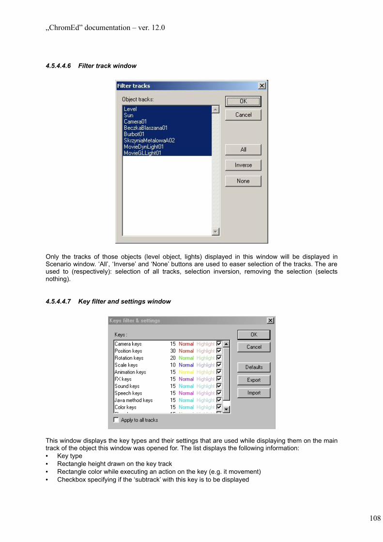
„ChromEd” documentation – ver. 12.0
4.5.4.4.6 Filter track window
Only the tracks of those objects (level object, lights) displayed in this window will be displayed in Scenario window. ‘All’, ‘Inverse’ and ‘None’ buttons are used to easer selection of the tracks. The are used to (respectively): selection of all tracks, selection inversion, removing the selection (selects nothing).
4.5.4.4.7 Key filter and settings window
This window displays the key types and their settings that are used while displaying them on the main track of the object this window was opened for. The list displays the following information:• Key type• Rectangle height drawn on the key track• Rectangle color while executing an action on the key (e.g. it movement)• Checkbox specifying if the ‘subtrack’ with this key is to be displayed
108

„ChromEd” documentation – ver. 12.0
Additionally, the following buttons are available:• ‘Defaults’ – loads the default settings• ‘Export’ – exports the settings to the file• ‘Import’ – imports the settings from the file• ‘Apply to all tracks’ checkbox – upon applying the changes the changes affect all tracks
4.5.4.4.8 Camera parameters window
The parameters you may set:1) ‘Name’ – camera name2) ‘Clipping planes’ section – enables to set the clipping plane distances:
a) ‘Near’ – forward planeb) ‘Far’ – back plane
3) ‘Loop all tracks’ section – enables to set the track loop modea) ‘no loop’ – the track doesn’t loop – while reaching its end the track remains unchangedb) ‘loop’ – regular track loop – while reaching its end the track goes to the first keyc) ‘smooth loop’ – smooth track loop – while reaching its end the track smoothly goes to the first
keyd) ‘ping pong loop’ – while reaching its end the track goes back from the end to the beginning
and so on4) ‘All tracks length’ – enables to specify all tracks length. It only matters in case of ‘smooth loop’
mode. It specifies the time of change to first key. The smooth change takes place form the last key position to the track length
4.5.4.4.9 ‘Subtrack’ parameters window
109

„ChromEd” documentation – ver. 12.0
The parameters you may set:1) ‘Length’ – the ‘subtrack’ length – see the ‘Camera parameters’ window description2) ‘Loop mode’ – defines the ‘subtrack’ loop mode – see the ‘Camera parameters’ window description
4.5.4.4.10 Adjust time window
This window enables to:1) Insert a time interval in the required place. All keys located behind the inserted interval move to
the right. To do so enter the required value in ‘Length’ field and set ‘From’ and ‘To’ values to ‘0’. The interval begins in ‘Current time’ and has ‘Length’ length
2) Remove the time interval from the selected place. The same as inserting the interval but in this case the ‘Length value’ must be negative. The length of the removed interval is absolute of ‘Length’ value
3) Rescale the time interval. If both ‘From’ and ‘To’ fields have values set then the time interval beginning in ‘Current time’ and ending in ‘From’ time is being rescaled to time interval with ‘To’ length
4) As above but with ‘End’ checked – the interval beginning in ‘Current time’ and editing at the film end is being rescaled to length described by ‘To’ value
NOTE: all times are given in seconds
4.5.4.4.11 Key attributes window
This window opens upon double clicking the key:
110

„ChromEd” documentation – ver. 12.0
This window is used for setting the key attributes. It is used for all key types but for various key types the various attribute list is. The attribute list may change during the work with that window (new attributes may appear). In case of most of the attributes you need to enter the values using the proper controls (edits or dropdown lists) but in some cases you may use the browsing button (as on the picture above presenting ‘MeshElement’ attributes.
‘Next’ and ‘Prev’ buttons (if available) enable to switch to next/previous key on the same track.
4.5.4.5 Camera selection
By left clicking the camera main track label in the context menu you select the camera to edit (it is unconditionally from the object selection in editor). Camera selection enables to:1) Quick creation of camera keys. Clicking the ‘Fr’ button on the toolbar automatically creates the
camera position and camera target position keys in the current film time in way that in the given film second the camera is positioned the same way as it is positioned in this moment in active viewport.
2) Edition of camera position and camera target position keys. The camera and camera target track are being visualized and for the selected key the object is being created that may be replaced with immediate change of the key vector
4.5.4.6 Point keys multiselection
Using the buttons on the toolbar (see – 6.5.3 Scenario window toolbar description) you may multiselect the various number of point keys at the same time. But the multiselection concerns only the key replacement – to edit the key attributes you have to select the single key.To multiselect the keys you have to:• Select the key• Press the multiselection button on the toolbar• Repeat the operation on the next keyEach key form the multiselection is being crossed by the red vertical line. To exclude the key from the multiselection you need to select it again. To exclude all keys from the multiselection use the proper button on the toolbar (see 6.5.3)
111

„ChromEd” documentation – ver. 12.0
4.6 TerrainEd
4.6.1 Purpose
During loading the level the terrain is being created according to height map. The map may be presented as the bitmap and the .height format file. The map size is crucial – it must be a square with side equal 2^n + 1, where n stands for any natural number. The minimum side length is ‘33’. The terrain size is strictly connected with the bitmap size – the terrain has the vertex number equal to bitmap pixel number. The difference between .height format file and the bitmap is then the .height format file is much more detailed because the vertex height is presented in 32bit resolution and in case of bitmap the resolution is 8bit.
The ‘TerrainEd’ plug-in enables to modify the existing terrain grid. It enables to change its size (vertex number in grid) and to modify the Y axis (height) of the given vertexes). The results of plug-in modifications are always stored in .height format file which becomes the level height map from now on (providing that the bitmap was defining the height map)
For terrain modifications you may use the predefined tool set which is described below:• ‘Blur’ – terrain smoothing• ‘Point height’ – setting the vertex height together with the nearby area• ‘Posterize’ – terrain leveling• ‘Relative height’ – relative change of the vertex height• ‘Ramp’ – ramp creation• ‘Set height‘ – seting the vertex height to a given value
4.6.1.1 Common setting for all tools
The common settings for all tools are the ones located in ‘Current brush’ section of the plug-in window (see 6.6.3) and are not in ‘Tool’ section:• Bitmap – defines the changes to be made in the given extent (see 6.6.1.2)• Extents (‘Extent’) – specifies the terrain part to be modified with single tool move• Power factor (‘Power’) – the value from [0, 1] range. Enables to manage the size of the changes
made (to decrease the changes size) – see 6.6.1.2• Fade factor (‘Fade’) – enables to specify the tool power decrease while using the tool with mouse
move (to ‘fade’ the tool) – see 6.6.1.2)• ‘Hardness’ factor – the parameter enabling to modify the changes from the bitmap. It does not
influence the bitmap pixels with ‘0’ brightness (that is not making any changes). It is added to all other pixels (enabling to brighten up the bitmap)
• Mask – works the same as ‘Mask bitmap’ attribute of brush used in ‘Forester’ plug-in (see 6.2.2.2)
4.6.1.2 Tool description
All tools work with the single move. The single move is defined as the time from pressing the left mouse button over the terrain and it release. Those moves can be ‘Undo’ and ‘Redo’ with the terrain editor (the buttons are located on the plug-in main window – see 6.6.3).
Each tool works differently while used (single move) but they can be divided onto few groups:• The tools that specify the terrain extent with single mouse click and the mouse move (with the
button pressed) defines the change scale e.g. ‘Point height’ tool• The tools that operate in all places pointed by the mouse cursor from the mouse click till the
mouse button release. The mouse move speed is considerable because it defines the operations number e.g. ‘Blur’, ‘Posterize’, ‘Relative heights’, ‘Set height’.
• The tools that only take the point of mouse clicking and the point of mouse button release and the calculations are being made according to those two points and the tool settings e.g. ‘Ramp’.
112

„ChromEd” documentation – ver. 12.0
‘Ramp’ tool considerably differs from all other tools and it is described in 6.6.1.8 (the further part of this subchapter doesn’t concern it.
All tools work as a series of operations. In case of ‘Point height’ tool all operations concern the very same area, in case of other tools each operation concerns different part of terrain (the mouse move speed specifies the changes between the parts). The part terrain size depend on the tool extent (‘Extent’).
Each operation is being done on the given set of terrain grid vertexes. According to the bitmap for each grid vertex the allowed change value is being specified defining the power of tool move in this point. The power is defined in % - the absolute change value is defined according to the tool and its internal settings. Here you define the percent of the changes the tool could make to the terrain vertex. The brighter point on the bitmap the higher power of the tool. Generally, color black (brightness ‘0’) does not inflict any changes.
The change values are also influenced by ‘Power’ and ‘Fade’ factors:• ‘Power’ factor is used the same way in all operations: the allowed change value is being multiplied
by the factor (so if ‘Power’ = 0 then no changes are made, if ‘Power’ = 1 then the maximum change value is set)
• ‘Fade’ factor results in decreasing the change value according to the distance in one move (this factor is being omitted in case of ‘Point height’ tool). The factor value defines the distance where the change value is ‘0’. In other words: if this factor value is set (different form ‘0’) then the ‘Power’ factor is being modified with the mouse move and ‘Fade’ factor specifies the distance where ‘Power’ factor decreases to ‘0’
When you already defined the vertexes set and for each of them the relative change is defined, then the tool specifies what change you want to make on the vertex and what percent of the change you want to make. The way of specifying the change depends on the tool only and is described while describing the following tools.
One move cannot make changes to one vertex greater then set for the tool for bitmap brightness = 255 and ‘Power’ factor = 1 (if not described differently while describing the tool).
4.6.1.3 ‘Blur’ tool
This tool is used for terrain leveling. It evens the nearby vertexes height according to changing vertex and sets that height to vertex.
Additional parameters of this tool:1) ‘Neighborhood size’ – the neighborhood size of the vertex that will be evened and will make the
vertex new height. The size is square with the side equal to 2*Neighborhood_size + 1 (the vertex is the size center)
2) ‘Use only dest buffer’ – specifies that upon one move you may set any given number of changes.NOTE: using this option makes the sometimes rapid changes. It is advised to use ‘Power’ factor <1 for this option.
3) ‘Mode’ – work mode. It enables to limit the modifying vertex set. You may choose from the following modes:a) ‘Default’ – all vertexes are being modifiedb) ‘Min’ – only those vertexes that are to be raised are being modifiedc) ‘Max’ – only those vertexes that are to be lowered are being modified
The suggested change of vertex height is defined in this way: change = neighborhood vertexes average height – current vertex height(the vertex always belongs to its neighborhood)
4.6.1.4 ‘Point height’ tool
113

„ChromEd” documentation – ver. 12.0
This tool is used to change on vertex neighborhood. It does not have any additional parameters. The suggested vertex height change depends on the mouse move and is equal to the vertical mouse move from the last operation (in game units)
4.6.1.5 ‘Posterize’ tool
This tool is used for leveling all the vertexes to level numbers specified by the ‘Height divisions number’ attribute value. The vertex height division is being divided by the level number and all vertexes are leveled to the nearest level.
Additional parameters of the tool:1) ‘Mode’ – work mode. It enables to limit the modifying vertex set. You may choose from the
following modes:a) ‘Default’ – all vertexes are being modifiedb) ‘Min’ – only those vertexes that are to be raised are being modifiedc) ‘Max’ – only those vertexes that are to be lowered are being modified
2) ‘Height division number’ – level number to which vertexes are being leveled3) ‘Use only dest buffer’ – specifies that upon one move you may set any given number of changes.
4.6.1.6 ‘Relative height’ tool
This tool is used for relative change of the vertex height. The suggested change value (‘Delta height’) is the only additional parameter of this tool.
4.6.1.7 ‘Set height’ tool
This tool is used for changing the vertex height to the given value.
Additional parameters of the tool:1) ‘Height’ – the height value to set to vertexes2) ‘Mode’ – work mode. It enables to limit the modifying vertex set. You may choose from the
following modes:a) ‘Default’ – all vertexes are being modifiedb) ‘Min’ – only those vertexes that are to be raised are being modifiedc) ‘Max’ – only those vertexes that are to be lowered are being modified
3) ‘Pick height’ – specifies if while starting the move the ‘Height’ parameter is being taken from the move starting point
The suggested vertex height change is defined as:Change = height – current vertex height
4.6.1.8 ‘Ramp’ tool
This tool is used for ramp creation. It works differently then other tools that is fully described in this chapter (chapter 6.6.1.2 does not concern this tool).
The move for ‘Ramp’ tool is defined the same way as it is for other tools but in this case only the starting and ending point of the move matters. Those two points define the ramp beginning and end. The ramp width is defined by ‘Extent’.
The ramp has the rectangle shape (from the top point of view). All vertexes of this rectangle are being modifying. Depending on the ‘Mode’ parameter the vertex set may be limited. The ‘Mode’ parameter is the same as in ‘Set height’ tool:
a) ‘Default’ – all vertexes are being modifiedb) ‘Min’ – only those vertexes that are to be raised are being modifiedc) ‘Max’ – only those vertexes that are to be lowered are being modified
114
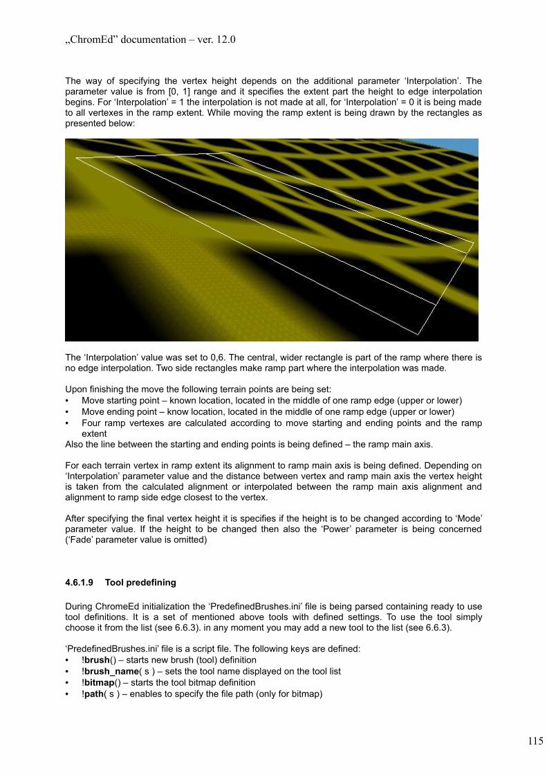
„ChromEd” documentation – ver. 12.0
The way of specifying the vertex height depends on the additional parameter ‘Interpolation’. The parameter value is from [0, 1] range and it specifies the extent part the height to edge interpolation begins. For ‘Interpolation’ = 1 the interpolation is not made at all, for ‘Interpolation’ = 0 it is being made to all vertexes in the ramp extent. While moving the ramp extent is being drawn by the rectangles as presented below:
The ‘Interpolation’ value was set to 0,6. The central, wider rectangle is part of the ramp where there is no edge interpolation. Two side rectangles make ramp part where the interpolation was made.
Upon finishing the move the following terrain points are being set:• Move starting point – known location, located in the middle of one ramp edge (upper or lower)• Move ending point – know location, located in the middle of one ramp edge (upper or lower)• Four ramp vertexes are calculated according to move starting and ending points and the ramp
extentAlso the line between the starting and ending points is being defined – the ramp main axis.
For each terrain vertex in ramp extent its alignment to ramp main axis is being defined. Depending on ‘Interpolation’ parameter value and the distance between vertex and ramp main axis the vertex height is taken from the calculated alignment or interpolated between the ramp main axis alignment and alignment to ramp side edge closest to the vertex.
After specifying the final vertex height it is specifies if the height is to be changed according to ‘Mode’ parameter value. If the height to be changed then also the ‘Power’ parameter is being concerned (‘Fade’ parameter value is omitted)
4.6.1.9 Tool predefining
During ChromeEd initialization the ‘PredefinedBrushes.ini’ file is being parsed containing ready to use tool definitions. It is a set of mentioned above tools with defined settings. To use the tool simply choose it from the list (see 6.6.3). in any moment you may add a new tool to the list (see 6.6.3).
‘PredefinedBrushes.ini’ file is a script file. The following keys are defined:• !brush() – starts new brush (tool) definition• !brush_name( s ) – sets the tool name displayed on the tool list• !bitmap() – starts the tool bitmap definition• !path( s ) – enables to specify the file path (only for bitmap)
115

„ChromEd” documentation – ver. 12.0
• !function( s ) – starts the function definition. The name of the function (described below) is the function parameter)
• !power_modifier( f ) – tool ‘Power’ factor• !usage_density( f ) – tool ‘Density’ factor - unused• !fade_factor( f ) – tool ‘Fade’ factor• !hardness( f ) – tool ‘Hardness’ factor• !vertical_distance( f ) – tool ‘Vertical distance’ factor• !extent( f ) – extent size• !mask( s ) – mask path. It exists in script file only in the situation, when it is to be used.• !attrib( s, s ) – parameter value. First string is parameter name, the other is its value.
‘PredefinedBrushes.ini’ file contains only some of the functions and their additional parameters (other are not recognized). Those are:1) ‘BlurFunction’
a) ‘Neighbourhood size’ (m_NeighbourhoodSize)b) ‘Use only destination buffer’ (m_UseOnlyDestBuffer)c) ‘Mode’ (m_Mode)
2) ‘PointHeightFunction’3) ‘PosterizeFunction’
a) ‘Mode’ (m_Mode)b) ‘Number of height divisions’ (m_NumHeightDivisions)c) ‘Use only destination buffer’ (m_UseOnlyDestBuffer)
4) ‘RelativeHeightFunction’a) ‘Delta height’ (m_Height)
5) ‘SetHeightFunction’a) ‘Height’ (m_Height)b) ‘Pick height’ (m_PickHeight)c) ‘Mode’ (m_Mode)
6) ‘RampFunction’a) ‘Mode’ (m_Mode)b) ‘Front – back interpolation’ (m_FrontBackInterpolation)c) ‘Side interpolation’ (m_SizeInterpolation)
Exemplary brush definition:
brush(){ brush_name( "set")
bitmap(){
path( ".\\data\\brushes\\round.png" )}function( "SetHeightFunction" ){
attrib( "m_Mode", "mode_default" )attrib( "m_Height", "500.000000" )attrib( "m_PickHeight", "0" )
}power_modifier( 1.00000 )usage_density( 1.00000 )fade_factor( 0.00000 )hardness( 0.00000 )extent( 3200.00000 )vertical_distance( 0.00000 )
}
4.6.2 Dependence on other plug-ins
The ‘TerrainEd’ plug-in depends on ‘Environment’ plug-in.
116

„ChromEd” documentation – ver. 12.0
4.6.3 User interface
Plug-in menu is titled ‘Terrain’. It consists of following options:• ‘Save height map...’ - saves terrain height map to a .height format file• ‘Edit bitmap on terrain’ - opens the ‘Edit bitmap on terrain’ window• ‘Export terrain extent to STL’ – exports part of terrain to a STL format file. Right after choosing this
option terrain extent must be marked in a 3d view. Next a dialog appears to enter a destination file name.
Plug-in toolbar consists only one option to open/close the plug-in form:
1.
4.6.3.1 Plug-in main form
117
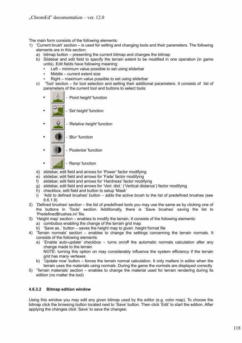
„ChromEd” documentation – ver. 12.0
The main form consists of the following elements:1) ‘Current brush’ section – is used for setting and changing tools and their parameters. The following
elements are in this section:a) bitmap button – presenting the current bitmap and changes the bitmapb) Slidebar and edit field to specify the terrain extent to be modified in one operation (in game
units). Edit fields have following meaning:• Left – minimum value possible to set using sliderbar• Middle – current extent size• Right – maximum value possible to set using sliderbar
c) ‘Tool’ section – for tool selection and setting their additional parameters. It consists of list of parameters of the current tool and buttons to select tools:
• - ‘Point height’ function
• - ‘Set height’ function
• - ‘Relative height’ function
• - ‘Blur’ function
• - ‘Posterize’ function
• - ‘Ramp’ function
d) slidebar, edit field and arrows for ‘Power’ factor modifyinge) slidebar, edit field and arrows for ‘Fade’ factor modifyingf) slidebar, edit field and arrows for ‘Hardness’ factor modifyingg) slidebar, edit field and arrows for ‘Vert. dist.’ (‘Vertical distance’) factor modifyingh) checkbox, edit field and button to setup ‘Mask’i) ‘Add to defined brushes’ button – adds the active brush to the list of predefined brushes (see
6.6.1.9) 2) ‘Defined brushes’ section – the list of predefined tools you may use the same as by clicking one of
the buttons in ‘Tools’ section. Additionally, there is ‘Save brushes’ saving the list to ‘PredefinedBrushes.ini’ file.
3) ‘Height map’ section – enables to modify the terrain. It consists of the following elements:a) combobox enabling the change of the terrain grid mapb) ‘Save as..’ button – saves the height map to given .height format file
4) ‘Terrain normals’ section – enables to change the settings concerning the terrain normals. It consists of the following elements:a) ‘Enable auto-update’ checkbox – turns on/off the automatic normals calculation after any
change made to the terrainNOTE: turning this option on may considerably influence the system efficiency if the terrain grid has many vertexes
b) ‘Update now’ button – forces the terrain normal calculation. It only matters in editor when the terrain uses the materials using normals. During the game the normals are displayed correctly
5) ‘Terrain materials’ section – enables to change the material used for terrain rendering during its edition (no matter the tool)
4.6.3.2 Bitmap edition window
Using this window you may edit any given bitmap used by the editor (e.g. color map). To choose the bitmap click the browsing button located next to ‘Save’ button. Then click ‘Edit’ to start the edition. After applying the changes click ‘Save’ to save the changes:
118
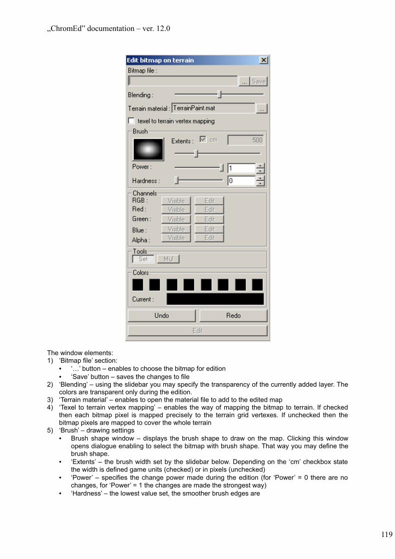
„ChromEd” documentation – ver. 12.0
The window elements:1) ‘Bitmap file’ section:
• ‘…’ button – enables to choose the bitmap for edition• ‘Save’ button – saves the changes to file
2) ‘Blending’ – using the slidebar you may specify the transparency of the currently added layer. The colors are transparent only during the edition.
3) ‘Terrain material’ – enables to open the material file to add to the edited map4) ‘Texel to terrain vertex mapping’ – enables the way of mapping the bitmap to terrain. If checked
then each bitmap pixel is mapped precisely to the terrain grid vertexes. If unchecked then the bitmap pixels are mapped to cover the whole terrain
5) ‘Brush’ – drawing settings• Brush shape window – displays the brush shape to draw on the map. Clicking this window
opens dialogue enabling to select the bitmap with brush shape. That way you may define the brush shape.
• ‘Extents’ – the brush width set by the slidebar below. Depending on the ‘cm’ checkbox state the width is defined game units (checked) or in pixels (unchecked)
• ‘Power’ – specifies the change power made during the edition (for ‘Power’ = 0 there are no changes, for ‘Power’ = 1 the changes are made the strongest way)
• ‘Hardness’ – the lowest value set, the smoother brush edges are
119

„ChromEd” documentation – ver. 12.0
6) ‘Channels’ – enables to view/edit in RGBA mode or in selected channels (some buttons might be disabled – it depends on the bitmap bit depth)• ‘Visible’ buttons – there are 5 buttons: ‘RGB’, ‘Red’, ‘Green’, ‘Blue’ and ‘Alpha’. Clicking ‘RGB’
button turns drawing in all three colors (regular view mode). Clicking any other button turns on/off the edition in this channel
• ‘Edit’ buttons – the same way as ‘Visible’ buttons but in this case using the buttons enables edition instead of viewing.
7) ‘Tools’ – additional brush properties• ‘Set’ – sets the brush in a common edition mode• ‘Mul’ – melts the current color with the color of the layer below (they layer you draw on)
8) ‘Colors’ – selects the brush color. The upper window contains all predefined colors. Under the window there is a window displaying the current color and the RGB value of this color. To change the color of drawing click on of the predefined color button. To change the predefined color double click the color button and choose new color from the dialogue.
9) ‘Undo’ / ‘Redo’ – enables to undo and redo the executed operations. During the edition it is the only way. ‘CTRL-Z’ and ‘Undo/Redo’ form the editor main menu do not work. The available number of undos depend on the tool stack and is defined in editor options (see 5.2.1)
10) ‘Edit’ – turns on/off the edit mode (the changes are being applied after clicking ‘Save’ button)
5 Physics
5.1 Purpose
Physics plug-in makes possible:
1. To attune and test object parameters connected with physics2. To lay out objects with use of physics
5.1.1 Attuning and testing object parameters connected with physics
There is a possibility to apply physical impulse to objects to test their behaviour in such a situation. Objects that are active (from the point of view of physics) can collide and activate other objects. Simulation can be stopped at any moment and it stops automatically when all objects have stabilized.
Objects must be of class LawmanASP or a class derived from it to be simulated with physics.
NOTE: Assumption: in ChromEd physics can activate and move only those objects, that have proper flag set. It can be done using ‘Attributes window’ and ‘Misc’ tab (‘emulate physics in editor’ checkbox). That flag has no influence upon game. Objects, that are not to be moved by physics in editor, should have this flag cleared.
NOTE: A physical impulse in ChromEd isn’t connected with applying any force to objects. It is only connected with activating physics and letting gravitation does its job.
5.1.2 Laying out objects with use of physics
There is a possibility to creating objects with applying a physical impulse to them automatically after their creation. For example it helps to create piles of rocks and stones.
5.2 User interface
User interface of Physics plug-in is merely a toolbar with two basics options available:
1. 2.1. Applies physical impulse to selected objects2. Stops any active physics simulation (for all objects)
120

„ChromEd” documentation – ver. 12.0
6 The rules of preparing java attributes to be edited with use of ChromEd
Objects of all java classes derived from GameObject may be edited with use of ChromEd. The system allows to decide which attributes are to be visible / editable. There must be defined an additional static String attribute of the same name, as an attribute that we want to be editable, but ended with additional Info string. For example:
class test extends GameObject { float m_Attribute; static String m_AttributeInfo = "f:EDIT;e:EDIT;d:test attribute;"; }
Types of attributes that can be defined this way (and edited later):• byte• short• char• int• long• float• double• boolean• String• Vector• reference to GameObject or any class derived from it• list of references to GameObject or any classes derived from it• classes derived from class Enum
6.1 Format of a string describing attributes in a custom RTTI system
An attribute describing string consists of any number of properties separated with semicolons. RTTI_string -> (Property‘;’)*
A property has a following format:Property -> Property_id ‘:’ Property_data
Property_id (property identificator) is a letter uniquely identifying given property:• F: flags, • E: edit flags, • C: category, • D: description, • M: minimum, • X: maximum, • S: step (for spinner controls), • A: additional data (its meaning depends on other properties), • P: package, • R: precision (for floating point attributes),
6.1.1 Flags (F)
Property data is a combination of flags and consists of flags separated with a ‘|’ character.
Property_data -> flag (‘|’ flag)*
121

„ChromEd” documentation – ver. 12.0
Available flags:• EXPOSE: an attribute is visible in an editor, (should not be combined with EDIT) • EDIT: an attributes value can be modified in an editor (should not be combined with EXPOSE), • DONT_SERIALIZE: an attribute value is not saved in a map file (by default all attributes, that
have their describing strings defined, are saved in .map files), • SAVEGAME: an attribute value is saved in savegame files, • REPLICATE: an attribute value is replicated in a network subsystem.
For example:
F: EDIT | DONT_SERIALIZE;
6.1.2 Edit flags (E)
Property data is a combination of edit flags that set up a way of modifying of this attribute value in editor. It consists of flags separated with a ‘|’ character.
Property_data -> flag (‘|’ flag)*
Available flags: • EDIT: an editbox control is used to modify value, • COMBO: a combobox is used to modify value,• SPINNER: a spinner control is used to modify value, • CHECKBOX: a checkbox is used to modify value, • EXPANDABLE: allows to expand of attributes that consists of many elemenets like vectors,
matrices, lists • BROWSE_COLOR: adds a button that shows a browse color window, • BROWSE_OBJECT: adds a button that shows a browse object window (from existing objects), • BROWSE_FILE: adds a button that shows browse file window, • BROWSE_MESH: adds a button that shows browse mesh (.msh or .3da file) window,• ADVANCED: an attribute is visible and editable only when ‘display advanced attributes’
checkbox is checked, • CONTEXT: value of this attribute can be set using context menu no matter if it is selected for
editing (an option connected with this attribute will be added to menu), • SHOW_DESCRIPTION: a description of this attribute shows as its name and vice versa,
There is defined a default control used to edit an attribute value for every allowed variable type. It can be EDIT, COMBO or CHECKBOX and it is used if none of these is defined in this property data. Controls are matched to types in a following way:
1.CHECKBOX: • boolean
2.COMBO: • Enum
3.EDIT: • byte • short • char• int • long • float• double• String• Vector
In case of Vector EXPANDABLE is additional default flag.
122

„ChromEd” documentation – ver. 12.0
For example:
E: BROWSE_OBJECT | CONTEXT | SHOW_DESCRIPTION;
6.1.3 Category (C)
Property data is string that is a name of category that attribute is assigned to in an editor.
For example:
C:AI;
6.1.4 Description (D)
Property data is string that is a text description of this attribute.
For example:
D:Density of rain drops;
6.1.5 Minimum (M), maximum (X) and step (S)
Property data are the boundary or step values of this attribute. For those types, that have many elements (like vectors), particular elements are separated by a space.
Example for Vector:
M: 0 0 0; X: 1 1 1; S: 0.1 0.1 0.1;
6.1.6 Additional data (A)
It is relevant only in connection with BROWSE_FILE edit flag. It makes possible to define strings that are used to browse files.
For example:
A:Scripts (*.scr)|*.scr; A:Scripts (*.scr)|*.scr|All files (*.*)|*.*;
6.1.7 Package (P)
It is relevant only in connection with BROWSE_FILE edit flag. It makes possible to use of predefined strings that are used to browse file (that can be achieved also by using ‘Additional data’ property). Several packages may be used at the same time.
Following strings are defined:- „all” – „All files (*.*)|*.*” - „mesh” – „Mesh files (*.3da; *.msh)|*.3da;*.msh” - „sound” – „Sound files (*.wav; *.ogg)|*.wav;*.ogg”
For example:
P:all;P:sound;
123

„ChromEd” documentation – ver. 12.0
6.1.8 Precision (R)
It is relevant only for floating point types. It specifies number of digits after the decimal point. It is used in all to and from string conversions (editing and visualisation in an editor).
For example:
R:10;
7 Dictionary
• AI – each object with Java class inheriting from NewAI class. Those are objects that have so called ‘intelligent behavior’ like the player and NPC (Non Playing Characters – live creatures not controlled by other players)
• FOV (Field Of View) – here it concerns only the camera field of view
• Gizmo – the virtual object representing an object position and orientation. In ChromeEd it may be connected with one object and then it specifies the position of the given object and presents the local axis coordination mode with axes parallel to world axes or with object selection and then it specifies the center of the selection
• Editor helpers – the objects that exist only in ChromeEd and don’t exist in the game. The list of that objects is created according to ‘Helpers.ini’ file and for each of them the following items are defined: name, java class, mesh and flag specifying if that helper may be added to the level with use of ‘Mesh Browser’ plug-in. Generally the helpers are connected to the given plug-in and only that plug-in really uses this helper. Each helper has Java class assigned that inherits from HelperEditorObjec class. The class of an existing helper cannot be changed. Those object exists only in editor because if there was no helpers then the edition would be much more difficult (e.g. lack of light or the patrol points - waypoints)
• Private object – the object that exists only for an public object (the owner). The only way to get to the private object is through an attribute of its owner. It concerns only those attributes that are pointers (references) to abstract classes are lists of pointers to abstract classes. None of objects can point at private objects. Private objects are destroyed when their owners are.
• Public object – the object that is created and visible in ChromEd in a standard way. All objects can point at them (including private ones).
• POV (Point Of View) – specified for each camera – it is camera position and camera orientation in world. For example – the view form a MeshElement POV means placing the camera in that MeshElement position and directing it according to Z axis of the MeshElement local coordination mode
8 SummaryBecause the application is still being developed this document also needs to be updated. The newer version of the document will most probably concern the editor version based on newer Chrome engine.
You need to have in mind the application bugs that might cause the data and time loss. It is advised to make a backup copies of the level and use the automatic backup tool (see 3.3)
124