energetics in robotic flight at small...
TRANSCRIPT

on June 3, 2018http://rsfs.royalsocietypublishing.org/Downloaded from
rsfs.royalsocietypublishing.org
ReviewCite this article: Karydis K, Kumar V. 2017
Energetics in robotic flight at small scales.
Interface Focus 7: 20160088.
http://dx.doi.org/10.1098/rsfs.2016.0088
One contribution of 19 to a theme issue
‘Coevolving advances in animal flight and
aerial robotics’.
Subject Areas:biomimetics
Keywords:aerial robots, unmanned aerial vehicles,
energetics, energy-aware motion planning,
aerodynamic and ground effects,
high-speed robotic flight
Authors for correspondence:Konstantinos Karydis
e-mail: [email protected]
Vijay Kumar
e-mail: [email protected]
& 2016 The Author(s) Published by the Royal Society. All rights reserved.
Energetics in robotic flight at small scales
Konstantinos Karydis and Vijay Kumar
Department of Mechanical Engineering and Applied Mechanics, University of Pennsylvania, Philadelphia,PA 19104, USA
KK, 0000-0002-1144-8260
Recent advances in design, sensing and control have led to aerial robots that
offer great promise in a range of real-world applications. However, one criti-
cal open question centres on how to improve the energetic efficiency of aerial
robots so that they can be useful in practical situations. This review paper
provides a survey on small-scale aerial robots (i.e. less than 1 m2 area foot
print, and less than 3 kg weight) from the point of view of energetics. The
paper discusses methods to improve the efficiency of aerial vehicles, and
reports on recent findings by the authors and other groups on modelling
the impact of aerodynamics for the purpose of building energy-aware
motion planners and controllers.
1. IntroductionSmall-scale unmanned aerial vehicles (UAVs) offer promise in several domains
that span from core academic research to defence and commercial applications.
Some key examples include robotic first responders [1], aerial manipulation [2],
cooperative construction [3], radiation detection [4] and intelligence, surveillance
and reconnaissance. Bioinspired aerial robots [5,6] can help study the trade-offs
in avian and insect flight. To realize the full potential of aerial vehicles in
applications, it is important to further insist on design and development.
The design and development process in small aerial robots has three steps:
building autonomy, improving reliability and testing across complex environ-
ments. The process is outlined in figure 1. Building autonomy ties to
developing and unifying algorithms for localization and mapping [7], state esti-
mation [8], motion planning [9,10], robotic vision [11] and control [12,13]. The
developed solutions are typically tested in (semi-)controlled environments.
Once a system is capable of autonomous operation, improving its reliability fol-
lows. This step is related to optimizing the system design according to practical
operational needs. Such needs include appropriate integration of software and
hardware, endurance optimization, and improvement of payload capacity and
system energetics. As in the previous step, developed solutions are typically
tested in (semi-)controlled settings. What follows then is extensive testing by
researchers, practitioners and users, in a wide variety of applications and
environments. Testing in practical situations, however, may in fact reveal limit-
ations in the reliability and autonomy of the aerial system at hand, leading the
designer back to one of the two previous steps (figure 1). These steps apply, in
principle, to the design and development of any aerial robot configuration.
1.1. Small-scale unmanned aerial vehicle configurationsSeveral UAV configurations at small scales have been studied (figure 2). The
most common configurations include fixed-wing aircraft, rotary-wing vehicles
and bioinspired flapping-wing designs [14]. Fixed-wing aircraft were intro-
duced first, drawing from the design methods for larger vehicles and
utilizing appropriate scaling laws [15]. They require low thrust-to-weight
ratio to operate [16] because wings provide lift, and they typically fly at high
speeds. They are also more energy-efficient in forward flight than rotary-
wing vehicles [17]. However, their inability to hover, or fly at low speeds
when needed, makes them less suitable than rotary-wing vehicles for
manoeuvring in cluttered environments [18].

buildingautonomy
improvingreliability
testingapplications users
semi-controlledenvironment
uncontrolledenvironment
Figure 1. Conceptual design and development process in small-scale aerial robots. The graph essentially summarizes the key steps to successfully steer autonomousaerial robots from the research and development phase to practical applications. (Online version in colour.)
fixedwing
rotarywing
flappingwing
ornithopters
insect-like
helicopters multicopters
quadrotors coaxial
ducted fan
fixed-wing
Figure 2. Illustrations of various UAV configurations. Each type of UAV has its own strengths and weaknesses, and has received different degree of adoption inapplications. (Online version in colour.)
rsfs.royalsocietypublishing.orgInterface
Focus7:20160088
2
on June 3, 2018http://rsfs.royalsocietypublishing.org/Downloaded from
Rotary-wing vehicles can execute vertical take-off and
landing (VTOL), hover and are highly manoeuvrable. These
features make them exceptional candidates for operation in
confined spaces [18,19]. The design of rotorcraft vehicles is
an active area of research, and several approaches have
been proposed. Successful designs include traditional heli-
copters, quadrotors and vehicles with more than four rotors
(multicopters), as well as coaxial [20–22] and ducted-fan
[23] rotorcraft. Among these designs, the quadrotor stands
out due to its simplicity in terms of fabrication and control.
Furthermore, the quadrotor offers promise in many appli-
cations [18], and it has a low cost of entry. As a result, it
has been widely adopted in both academia and industry.
In several cases (e.g. going through crevices or in swarms),
there is need to shrink the aerial vehicles down to the sub-
millimetre scale [24]. However, fixed-wing and rotary-wing
vehicles do not scale down well [17,25]. The miniaturization pro-
blem arises primarily because the propulsion systems employed
in these vehicles perform poorly when scaled down [25]. This
inefficiency is further aggravated by the unsteady aerodynamics
that govern flight at low Reynolds numbers [26]. An alternative
paradigm to circumvent these challenges is the introduction of
bioinspired flapping-wing robots [27,28].
Flapping-wing vehicles include bird-like ‘ornithopters’
[5,29–32] and insect-like robots [6,33,34]. Ornithopters gener-
ate lift by flapping their wings with synchronized small
variations of angle of incidence. Their wings also contribute
to thrust generation for forward flight. Ornithopters generally
lack VTOL capabilities (with a few exceptions [30]), and they
need to obtain an initial airspeed to take off [35,36]. They are
more agile than fixed-wing vehicles [27], but aeroelasticity
and the fluid–structure coupling are currently not well
understood [37]. Insect-like aerial robots rapidly change the
angle of incidence to generate lift and thrust. They are
capable of VTOL, hovering and forward flight [6,33]. How-
ever, their advantage over rotary-wing vehicles in terms of
efficiency [25], endurance or manoeuvrability is not yet
clear. Furthermore, they increase the mechanical and controls
complexity [38]. Despite recent progress in navigation and
control [39–42], autonomous operation of flapping-wing
vehicles appears to remain limited.
Table 1 outlines how four types of aerial vehicles that are
currently capable of autonomous operation compare to each
other. The comparisons are made on the basis of six impor-
tant criteria for operation in practical situations. These are
manoeuvrability, control simplicity, endurance, payload
capacity, mechanical simplicity and low cost of entry. From
table 1, it can be readily verified that vehicles capable of
hovering are currently best suited for applications that
require autonomy. Unfortunately, VTOL and hovering have
high power requirements [18,43], rendering the improvement
of the energetics of robotic flight even more pressing.
Remark: Most of the results presented herein are obtained
from studies with quadrotors. The quadrotor has been
proven successful in a variety of contexts [18], and thus
offers a trustworthy testbed for studies in autonomy and
energetics in particular. Nonetheless, the ideas put forward
in the reported results can also be generalized to other
small-scale UAV configurations.
1.2. Energetics of small rotorcraftDespite the significant advances made in the area of aerial
robots [17,18], one remaining key challenge centres on sustain-
ing long-term autonomous operation. Unfortunately, current
maximum flight times under ideal operational conditions are

Table 1. Assessment of key characteristic features for aerial vehicles used in applications that require autonomy.
vehicle type fixed-wing helicopter quadrotor multicopter
manoeuvrability in tight spaces þþ þþþ þþþþ þþþcontrol simplicity þ þþ þþþþ þþþþendurance þþþþ þþþ þþ þþpayload capacity þþ þþþ þþþ þþþþmechanical simplicity þþþ þ þþþþ þþþlow cost of entry point þþ þþþ þþþþ þþþ
rsfs.royalsocietypublishing.orgInterface
Focus7:20160088
3
on June 3, 2018http://rsfs.royalsocietypublishing.org/Downloaded from
restrictive for most practical applications. Maximum flight
times for centimetre-scale aerial vehicles (e.g. the Crazyflie
(https://www.bitcraze.io/crazyflie-2/) and Pico [44] quadro-
tors) are approximately 5–7 min. Larger, decimetre-scale
vehicles such as Asctec’s Pelican (http://www.asctec.de/en/
uav-uas-drones-rpas-roav/asctec-pelican/) and DJI’s Phantom
4 (http://www.dji.com/phantom-4) quadrotors can operate
for up to 30 min. In typical operational conditions, the expected
flight times for decimetre-scale quadrotors range between 10
and 20 min [18], depending on payload and aggressiveness of
flight. In this light, how can we improve the capacity of aerial
robots for reliable, long-term operation?
To answer this question one can look at (i) improving the
efficiency of batteries or other power sources, (ii) developing
automated recharging methods, and (iii) improving the
vehicles’ energy efficiency. The efficiency of power sources
is typically captured well by the source specific energy and
power [43]. The source specific energy (measured in
Wh kg21) represents the total energy being available to the
system. The source specific power (measured in W kg21)
relates to the power that can be delivered to the vehicle
instantaneously. To date, most aerial robots employ
lithium–polymer (LiPo) batteries [18]. Such batteries offer
acceptable specific energy at high specific power (typically
in the range 100–150 Wh kg21 at over 1000 W kg21), and
retain performance over hundreds of charging/discharging
cycles [45]. Also, many different battery sizes to select from
according to the application at hand are commercially avail-
able. At the same time, quadrotors have been found to
consume about 200 W kg21 on average [18,43]. To improve
endurance, there is need for power sources with higher specific
energy instead. To this end, a promising alternative would be
lithium–sulfur (LiS) batteries. Such batteries can store double
or more specific energy than LiPo batteries at similar or even
higher specific power levels [46]. However, they are not com-
mercially available yet. Other power options for which
prototype UAVs exist include (hydrogen) fuel cells for rotor-
craft (http://www.hus.sg/hydrogen-multi-rotor) [47], and
micro-rockets [48] for insect-like vehicles. Another interesting
power source would be micro thermo-photo-voltaic (mTPV)
cells [49,50], but scaling important components for system
integration is still under research.
Some applications (e.g. persistent monitoring or airborne
delivery tasks) require redundancy in terms of the number of
vehicles to be deployed. In such cases, a different approach
would be to use docking stations for automatic battery
charging and/or swapping. Charging-only docking stations
typically feature contact-based battery charging [51], or
charging using a tether.1 As an alternative, one can consider
using devices and methods to both swap and charge batteries
[53–55]. Such approaches can reduce the time a vehicle
remains idle and thus increase efficiency and vehicle utiliz-
ation [55]. Despite these benefits, using docking stations
adds another layer of complexity, which may not always be
desirable. In some cases (e.g. availability of direct line of
sight, and operation in non-cluttered environments), remote
charging through laser [56] or magnetic resonance [57]
power beaming could be another possible solution.
A third approach to boost the long-term operation of
UAVs is by designing systems that consume as little energy
as possible, and are energy-efficient. The main purpose of
this paper is to identify ways to improve the energy efficiency
of aerial robots, and discuss relevant open challenges.
1.3. How to improve energy efficiency?To address the energy consumption challenge, this review
paper focuses on recent advances in hardware and algorithm
optimization, and multimodal locomotion.
1.3.1. Hardware-based optimization for energy efficiencyPerhaps the most straightforward way to reduce energy con-
sumption is to minimize the weight of the vehicle. This can be
achieved by using light-weight manufacturing materials [58],
electronics2 and sensors (such as cameras). In addition, care-
ful component selection and system design [59,60] can help
further. Hardware-based optimization is in fact well studied;
here we present some of the most promising results.
1.3.2. Algorithm-based optimization for energy efficiencyLess studied but equally significant is the development of
novel motion planning and control algorithms that are
energy-aware. Energy-aware algorithms reduce energy con-
sumption and extend flight times through the design of
energy-efficient trajectories to be tracked by an aerial vehicle
[61–64]. These algorithms can also benefit by using models
that explicitly take into consideration various aerodynamics
that affect energy consumption. To this end, we present results
that seek to model rapid descent [65,66], drag [65,66] and
ground effects [65,67–69]. We also present our preliminary
new results that relate energy consumption to high-speed
flight, indoors. Taken together with weight optimization, soft-
ware-based solutions to save energy can lead to aerial robots
capable of sustaining long-term operation.
1.3.3. Bio-inspired multimodal operation capabilitiesMore traditional works in design, planning and control for
robotic flight focus on monolithic, flying-only approaches.
This is in stark contrast with nature, where multimodal

rsfs.royalsocietypublishing.orgInterface
Focus7:20160088
4
on June 3, 2018http://rsfs.royalsocietypublishing.org/Downloaded from
behaviours are actually the norm (e.g. flying and walking).
Drawing inspiration from nature, the focus on robotic flight
has started to swift toward explicitly considering multimodal
robot design and operation [17]. Doing so may have signifi-
cant impact toward better energy utilization depending on
the given task. We present results on aerial vehicles that
can perch [70–72], walk [73,74], run [35] and roll [75].
Overall, improving the capacity of aerial robots for
reliable and persistent operation will be valuable in several
ways. Foremost, it will solidify the practical utility of aerial
robots in real-world applications. Second, long-term oper-
ation will enable research on developing autonomous
motion planning, control and machine learning algorithms
that require long-term operation data. Furthermore, it will
allow the experimental validation of various deployment
[1,76] and persistent monitoring [77,78] algorithms.
1.4. OrganizationThe remainder of this review paper is organized as follows.
Section 2 focuses on hardware-based optimization to reduce
weight. Section 3 expands on algorithm-based approaches
to improve energy efficiency, and reports on our preliminary
new results on energetics of high-speed flights. Section 4 pre-
sents recent efforts on designing multimodal aerial robots.
We discuss main findings at the end of each of §§2–4, and
conclude in §5. For the convenience of the reader, we provide
a list of symbols used in this review in appendix A.
2. Hardware-based efficiency optimizationThis section focuses on how we can design energy-efficient
systems from a hardware point of view. Reducing unnecess-
ary weight either by careful component selection or system
design will make a big impact to the energy consumption
of a vehicle at hand.
2.1. Weight reductionA direct way to reduce weight is to optimize the airframe
design of the aerial vehicle. One example is to use airframes
made of carbon fibre. Owing to its low weight and high
strength properties [58], carbon fibre has already become the
material of choice for large aircraft design [79]. It has also
found use in aerial robots across scales. Examples range from
the insect-scale robobee [6] to the popular 540 mm Asctec
Hummingbird quadrotor (http://www.asctec.de/en/uav-
uas-drones-rpas-roav/asctec-hummingbird/) and the 2 m
wingspan ornithopter Phoenix [29]. Another way to further
reduce the weight of an aerial robot is to design its printed cir-
cuit board (made of fibreglass [80]) so that it can serve as the
main part of the airframe. While fibreglass may be a non-optimal
material choice for airframe design [58,79], it offers an elegant
way to scaling quadrotors down to the centimetre scale [44].
Furthermore, advances in manufacturing electronic com-
ponents can provide an alternative leeway to reducing weight.
Indeed, we witness a period at which improved computing
and sensing packages for robotics applications are more avail-
able than ever. For example, in our experiments reported in
§3.3 we use a 16 g Odroid-c0 microcomputer (http://www.
hardkernel.com/main/products/prdt_info.php) on an Asctec
Hummingbird quadrotor. Despite its size, this microcomputer
is capable of running onboard all control algorithms for
semi-autonomous operation. (Localization is provided by a
motion capture camera system.) If onboard state estimation
via cameras is needed, then a 72 g Odroid-xu3 microcomputer
can be used instead [2]. Current ongoing work in our group
demonstrates that fully autonomous operation (including
localization and mapping) can be performed by employing
a 450 g (including the case, SSD, and RAM) Intel NUC
mini PC (http://www.intel.com/content/www/us/en/nuc/
nuc-kit-nuc5i7ryh.html). As a matter of fact, control electronics
are getting less expensive, more powerful, and with smaller
footprints, following trends predicted by Moore’s law [81].
One would argue that the same holds also for light-weight
sensors,3 thus constantly driving the weight of an aerial
vehicle down.
Unfortunately, batteries do not follow Moore’s law, and
continue to account for 25–50% of the weight of small
UAVs [18]. Therefore, further optimization is required. To
this end, current aerial robot designs can benefit from follow-
ing closer existing aerodynamic and light-weight structure
design principles for efficiency [79]. An alternative way is
to reconsider the vehicle design in its entirety. The latter is
the focus of the section that follows.
2.2. Improving efficiency via mechanical (re-)designAnother hardware-based means to increase the endurance of
an aerial robotic vehicle is by making appropriate modifi-
cations in its mechanical design. This is a less explored area
than weight reduction, yet some interesting approaches
have been proposed.
Driessens & Pounds [59] introduce a more efficient rotor
configuration termed ‘triangular quadrotor’. The proposed
configuration employs a centrally located large rotor tasked
to generate lift, and three smaller peripherally arranged
rotors that are used for control. The small rotors are tilted
so to produce the appropriate counter-moment to the vehicle.
This arrangement aims to combine the energetic efficiency of
a helicopter with the mechanical simplicity of a traditional
quadrotor. Compared with a traditional quadrotor, the pro-
posed triangular quadrotor is found to achieve a 15%
reduction in the power required to hover [59].
Another interesting approach adds servo motors to the tip
of each arm of a quadrotor design to allow tilting of the
vehicle’s motors [60]. This gives rise to an overactuated
system. While this type of overactuation does not seem to
offer any benefits in terms of energetic efficiency in hover, it
may show promise during forward flight. Indeed, it is plaus-
ible that overactuation may actually help design more
energy-efficient trajectories to be tracked by the vehicle in
forward flight.4
2.3. DiscussionOverall, when designing energy-efficient aerial vehicles it is
important to take into consideration their intended operation
and the associated task specifications (e.g. payload capacity,
autonomy capabilities, desired endurance, etc.). To this end,
there is need for careful component selection, which turns
out to be an interesting system design problem. Critical in
this process is the selection of the propulsion system, which
also consumes most of the power [43]. For robots capable
of hovering, the rule of thumb is that components should
be selected so that the vehicle’s thrust-to-weight ratio is
about two during hover, and while carrying the desired

rsfs.royalsocietypublishing.orgInterface
Focus7:20160088
5
on June 3, 2018http://rsfs.royalsocietypublishing.org/Downloaded from
payload. This way, the vehicle will be responsive to user com-
mands, and able to operate smoothly without risking motor
saturation during a possible aggressive manoeuvre. For rotor-
craft, in particular, the diameter and pitch of the propeller are
important determinants of energy efficiency. Indeed, as the
radius of the propeller rp increases, the rotor produces more
thrust Tr per unit power Pr as suggested by the simplified
expression in hover [65],5
Pr ¼Tr
hrrp
ffiffiffiffiffiffiffiffiffiffi2rap
p : ð2:1Þ
In (2.1), ra is the density of air and hr is the figure of merit
for the particular system—this is a measure of the efficiency
of the rotor [65]. However, merely using larger propellers
does not solve the problem because larger propellers
require a larger frame to fit, which in turn increases the
weight of the vehicle. Similarly, the rotor efficiency increa-
ses when one uses high voltage batteries, together with
motors of low motor velocity constant (Kv is expressed in
r.p.m. per volt), and long propellers. But the weight of the
vehicle also increases.
Remark: We emphasize that this is an intentionally brief
discussion on component selection, offered here in an effort
to give the reader a flavour of the delicate trade-offs when
designing an aerial vehicle. Tools like ecalc (http://www.
ecalc.ch/) offer a place to start at, but actual testing is in
fact needed to properly design an aerial system according
to given specifications.
The vehicle’s endurance te (in hover) can then be esti-
mated as the ratio of the total energy available to required
power,
te ¼Ebmb
npPr þ Pi: ð2:2Þ
In (2.2), Eb is the battery specific energy (in Wh kg21), mb is the
mass of the battery in kilograms, np denotes the number of
rotors and Pi represents the power required by all other com-
ponents (i.e. avionics and sensors). Abdilla et al. [82] develop
a more detailed model to estimate the endurance in hover.
While less explored, thinking out of the box during initial
mechanical design may have a large impact in terms of
energy efficiency. Key to this is a solid understanding of
how thrust is being generated for a particular propulsion
system. For example, the triangular quadrotor [59] was
motivated by the observation that the power required to
hover is inversely proportional to the propeller radius (see
(2.1)). Given a vehicle’s footprint, a single large rotor will
then outperform (energetically) several smaller rotors.
The smaller rotors are still needed though to improve the
controllability properties of the system [59].
In all, trying to keep the weight as low as possible is guar-
anteed to increase the endurance of the vehicle. There exist
cases, however, where this is not possible. For instance, one
needs to work with a preconfigured system, or the system
is already well configured. In such cases, algorithm-based
solutions can be brought to bear on sustaining long-term
operation. We address this topic next.
3. Algorithm-based efficiency optimizationIn this section, we discuss how to save energy and extend
endurance for robotic flight via software. We present recent
results in energy-aware motion planning for aerial vehicles—
rotorcrafts in particular. We also discuss approaches to capture
and model various aerodynamic effects that can be incorpor-
ated into motion planners and controllers to reduce energy
expenditure. The various aerodynamic effects we consider
typically depend on the vehicle’s ground speed. To this end,
we also report some preliminary new results on energy
consumption of high-speed robotic flight, indoors.
3.1. Energy-aware motion planningThe problem of generating energy-optimal paths for a rotor-
craft has only recently started receiving attention. One idea
is to formulate an optimal control problem to generate
paths that minimize the energy consumed with respect to
motor angular velocities and accelerations [61], or only
motor angular velocities [60]. For a traditional quadrotor con-
figuration, and under the condition that the motor angular
velocities are identical at the initial time, ti, and final time,
tf, a candidate cost functional is [61]
E ¼ðtf
ti
X4
j¼1
ðc0 þ c1vjðtÞ þ c2v2j ðtÞ
þ c3v3j ðtÞ þ c4v
4j ðtÞ þ c5 _v2
j ðtÞÞ dt: ð3:1Þ
The constants ci, i ¼ 1, . . . ,5 are determined based on the par-
ameters of the motors, and on the geometry of the propellers.
vj and _vj, j ¼ f1, 2, 3, 4g denote the jth motor angular vel-
ocities and accelerations, respectively. The optimal control
problem is further simplified via an appropriate change of
variables and then solved numerically; the reported approach
is tested in simulation and shows promising results [61]. The
reported analysis can perhaps be adapted to other types of
multicopter vehicles.
For the overactuated quadrotor configuration [60], a
different cost functional based on motor angular velocities
only is proposed. However, it appears that the reported
cost functional does not fully exploit the overactuation feature
of the employed vehicle. The vehicle is also found less
energy-efficient in hovering compared with the traditional
quadrotor configuration [60]. Still, appropriate shaping of
the employed cost functional may yield improved energy
efficiency in forward flight.
A different approach focuses on coverage path planning
with energy-based optimization criteria [62]. Each path is
designed as a concatenation of elementary manoeuvres,
with predetermined energy consumption. These include the
energy consumed for take off (Etoff ) and landing (Eland)
with respect to a fixed setpoint, turning in place (Eturn) at a
constant yaw rate, and moving on a straight line in two
dimensions at constant velocity (Emove). Straight-line
segments comprise a smooth acceleration phase, a constant-
velocity part, and a smooth deceleration phase. The energy
consumption of each of these segments is also predeter-
mined, and added up to yield Emove. In this light, the total
energy consumption for a path consisting of nsl straight-line
segments, and nt turns can be calculated by [62]
Etotal ¼ Etoff þ Eland þ ntEturn þXnsl
Emove: ð3:2Þ
Then, an optimization routine identifies the optimal forward
velocity in the constant-velocity part so that the energy cost
(3.1) is minimized.
(a) (b) (c) (d)
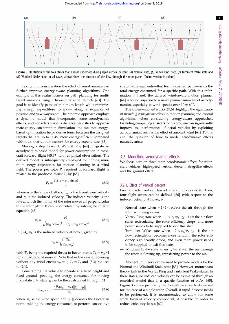
Figure 3. Illustration of the four states that a rotor undergoes during rapid vertical descent. (a) Normal state, (b) Vortex Ring state, (c) Turbulent Wake state and(d ) Windmill Brake state. In all cases, arrows show the direction of the flow through the rotor plane. (Online version in colour.)
rsfs.royalsocietypublishing.orgInterface
Focus7:20160088
6
on June 3, 2018http://rsfs.royalsocietypublishing.org/Downloaded from
Taking into consideration the effect of aerodynamics can
further improve energy-aware planning algorithms. One
example in this realm focuses on path planning for multi-
target missions using a hexacopter aerial vehicle [63]. The
goal is to identify paths of minimum length while minimiz-
ing energy expenditure to move along a sequence of
position and yaw waypoints. The reported approach employs
a dynamic model that incorporates some aerodynamic
effects, and considers various distance heuristics to approxi-
mate energy consumption. Simulations indicate that energy-
based optimization helps derive tours between the assigned
targets that are up to 11.4% more energy-efficient compared
with tours that do not account for energy expenditure [63].
Moving a step forward, Ware & Roy [64] integrate an
aerodynamics-based model for power consumption in rotor-
craft forward flight [65,67] with empirical observations. The
derived model is subsequently employed for finding mini-
mum-energy trajectories for motion planning in a wind
field. The power per rotor Pr required in forward flight is
related to the produced thrust Tr by [65]
Pr ¼Trðvi þ v1 sinaÞ
hr
, ð3:3Þ
where a is the angle of attack, v1 is the free-stream velocity
and vi is the induced velocity. The induced velocity is the
rate at which the motion of the rotor moves air perpendicular
to the rotor plane. It can be calculated by solving the quartic
equation [65]
vi ¼v2
hffiffiffiffiffiffiffiffiffiffiffiffiffiffiffiffiffiffiffiffiffiffiffiffiffiffiffiffiffiffiffiffiffiffiffiffiffiffiffiffiffiffiffiffiffiffiffiffiffiffiffiffiffiffiffiffiffiffiffiffiðv1 cosaÞ2 þ ðvi þ v1 sinaÞ2
q : ð3:4Þ
In (3.4), vh is the induced velocity at hover, given by
vh ¼ffiffiffiffiffiffiffiffiffiffiffiffiffiffiffi
Th
2rapr2p
s, ð3:5Þ
with Th being the required thrust to hover, that is Th ¼ mg/4
for a quadrotor of mass m. Note that in the case of hovering
without any wind effects v1 ¼ 0, Th ¼ Tr and (3.3) reduces
to (2.1).
Constraining the vehicle to operate at a fixed height and
fixed ground speed vg, the energy consumed for moving
from state qi to state qj can be then calculated through [64]
Esegment ¼4Prðvg � vwÞjjqj � qijj
vg, ð3:6Þ
where vw is the wind speed and jj � jj denotes the Euclidean
norm. Adding the energy consumed to perform consecutive
straight-line segments—that form a desired path—yields the
total energy consumed for a specific path. With this infor-
mation at hand, the derived wind-aware motion planner
[64] is found superior to a naive planner unaware of aerody-
namics, especially at wind speeds over 10 m s21.
The aforementioned works [63,64] highlight the significance
of including aerodynamic effects in motion planning and control
algorithms when considering energy-aware approaches.
Providing compelling answers to this problem can significantly
improve the performance of aerial vehicles by exploiting
aerodynamics, such as the effect of ambient wind [64]. To this
end, the question of how to model aerodynamic effects
naturally arises.
3.2. Modelling aerodynamic effectsWe focus here on three main aerodynamic effects for rotor-
craft vehicles: high-speed vertical descent, drag-like effects
and the ground effect.
3.2.1. Effect of vertical descentFirst, consider vertical descent at a climb velocity vc. Then,
four flight states can be defined [66] with respect to the
induced velocity at hover, vh.
— Normal state when 21/2 , vc/vh; the air through the
rotor is flowing down.
— Vortex Ring state when �1 , vc=vh � �1=2; the air flow
starts recirculating, the rotor efficiency drops, and more
power needs to be supplied to exit this state.
— Turbulent Wake state when �2 , vc=vh � �1; the air
flow recirculation becomes more random, the rotor effi-
ciency significantly drops, and even more power needs
to be supplied to exit this state.
— Windmill Brake state when vc=vh � �2; the air through
the rotor is flowing up, transferring power to the air.
Momentum theory can be used to provide models for the
Normal and Windmill Brake state [83]. However, momentum
theory fails in the Vortex Ring and Turbulent Wake states. In
these states, the induced velocity can be estimated through an
empirical model that is a quartic function of vc/vh [65].
Figure 3 shows pictorially the four states at vertical descent
for the case of a single rotor. Overall, if rapid descent needs
to be performed, it is recommended to allow for some
small forward velocity component, if possible, in order to
reduce efficiency losses [67].

0 5 10 15
0
0.1
0.2
0.3
0.4
0.5
0.6
0.7
0.8
0.9
1.0
0
0.1
0.2
0.3
0.4
0.5
0.6
0.7
0.8
0.9
1.0
t (s)
z(m
)
0 5 10 15t (s)
0.4
0.5
0.6
z(m
)
t (s)15 16 17 18 19 20
(a) (b)
Figure 4. (a) Data-driven model performance using the POD-based approach [68]. Model-predicted response (shown in red) is plotted against sample means(dashed black curves) and one standard deviation around the latter (solid grey curves). The predictive capacity of the derived data-driven model is tested andvalidated against the system behaviour when tasked to hover at jzj ¼ 20 cm from the ground. The graph is taken from Karydis & Hsieh [68] with permissionfrom the authors. (b) Performance of the stochastically extended model [69] to capture the steady-state behaviour of a quadrotor tasked to hover at various heightsfrom the ground. Monte Carlo simulation of the derived model reveals that the latter can capture the variability observed in experimental data. Red curves indicateindividual stochastic model realizations, and are plotted against the sample means (solid thick curves) and three standard deviations (dashed thick curves) ofexperimental data. The graph is taken from Karydis et al. [69] with permission from the authors.
rsfs.royalsocietypublishing.orgInterface
Focus7:20160088
7
on June 3, 2018http://rsfs.royalsocietypublishing.org/Downloaded from
3.2.2. Drag effectsWe now turn our attention to drag and drag-like effects.
Bangura & Mahony [66] propose a simple lumped parameter
nonlinear model for drag effects. The model can be incorpor-
ated in the rotorcraft dynamics, and it is designed so that it is
valid over the full vehicle flight envelope (not just in steady
state). Five drag components are considered.6
— Blade flapping, which is proportional to the vehicle’s
angular velocity and linear velocity in the x–y plane.
— Induced drag, which is proportional to the vehicle’s
planar linear velocity.
— Parasitic drag, also proportional to planar linear velocity.
— Translational drag, which is proportional to planar linear
velocity but at high velocities the vertical component of
the vehicle’s velocity and the induced velocity need to
be accounted for.
— Parasitic drag, which scales with the square of the three-
dimensional velocity of the vehicle.
The total drag force acting on the vehicle is the sum of all
the above components, taken over all rotors. The first four
drag components also create additional torque. The torques
created as a result of drag forces on individual rotors are
added to take the total additional torque on the vehicle
[66]. Including the effect of drag as additional force and
torque terms in a model for a rotorcraft is helpful in two
ways. Foremost, it allows the designer to study how the
energy expenditure due to drag varies. Second, it enables
the generation of motion trajectories that explicitly take into
consideration the effect of drag. Similar benefits can also be
gained by modelling ground effects.
3.2.3. Ground effectThe ground effect is known to manifest itself through an
increase in the lift of the vehicle. Specifically, the downward
airflow generated by the rotors of the platform redirects the
flow parallel to the ground plane, which in turn increases
the effective lift generated by the system. Blade element
and momentum theory has been used to provide an analyti-
cal model to capture the increase in the effective lift for a
single rotor as [84]
T0rTr¼ 1
1� (rp=4jzj)2f1=1þ ðjVj=viÞ2g: ð3:7Þ
In (3.7), rp is the radius of the propeller, jzj is the distance
from the ground, jVj is the vehicle’s speed, and vi is the
induced velocity. T0r and Tr denote the thrust close to and
away from the ground, respectively. Note that (3.7) indicates
that the ground effect practically diminishes when
jzj=rp � 2:5. However, this result is for one rotor, and does
not take into consideration the effect of adjacent rotors in a
multi-rotor vehicle. This perhaps explains the discrepancies
observed between (3.7) and the experimental results obtained
in some recent studies on ground effect for rotorcraft [85–87].
The ground effect can also be captured through data-
driven [68] or appropriate low-dimensional stochastic [69]
models. Karydis & Hsieh [68] derive a data-driven model
based on the principal orthogonal decomposition (POD)
[88,89] to capture the ground effect for a hovering quadrotor.
The idea is that primary modes extracted from altitude data
away from the ground capture the principal dynamics (in
this case, of a second-order system). The principal mode is
scaled and subtracted from data collected at other heights
inside the ground effect zone. Using POD again, secondary
modes are subsequently extracted. The latter are also scaled
and subtracted from data of hovering very low to the
ground. The primary mode of what remains is termed the
‘ground effect mode’. It is found that three modes (ground
effect, principal and an intermediate one) suffice to predict
the average behaviour of the system in other hovering altitudes
[68]. This is achieved by identifying appropriate scaling func-
tions that can map the constructed principal modes back to
altitude data for hovering at different setpoints. Figure 4ademonstrates this point pictorially. The proposed model is
trained based on the datasets collected when the vehicle was

ground speed,V (m s–1)0 2 4 6 8 10 12
pow
er r
atio
, P/P
h
0.6
0.8
1.0
1.2
1.4
1.6
1.8
2.0
Figure 5. Power consumption data normalized by the power consumption athover. Blue markings denote the results calculated by (3.3) – (3.5) using themeasured velocity from motion capture, and the thrust commands sent to thevehicle. A third-order polynomial model fits the data well (shown with a thickcurve), while its prediction at speeds over 8 m s21 (shown with a dashedcurve) seems to be in agreement with the theory [66].
rsfs.royalsocietypublishing.orgInterface
Focus7:20160088
8
on June 3, 2018http://rsfs.royalsocietypublishing.org/Downloaded from
commanded to hover at 50 cm, 11 cm and 2 cm, and tested
against the dataset with the hovering setpoint at 20 cm. With
reference to figure 4a, sample means are marked with
dashed black curves and one standard deviations around the
mean are shown with solid grey curves. The output of the pro-
posed data-driven model based on POD analysis closely
predicts the sample mean of the testing dataset at 20 cm, and
even captures the transient effects.
In a separate effort, Karydis et al. [69] propose a systema-
tic approach to bridge data-driven and model-based machine
learning. The reported approach starts with a deterministic
model that captures salient system behaviours, and extends
it to a stochastic regime by turning its parameters to
random variables. Experimental data are then used to esti-
mate the parameters of the distribution that the random
variables should be drawn from. The parameter estimation
is performed so that the output of the derived stochastic
model captures the variability observed in the original
system behaviour. The approach comes with probabilistic
guarantees on the validity of the outcome [69]. Figure 4bshows its application on the same dataset as before [68].
The model tested is a double integrator with zero-mean
Gaussian noise corrupting its output. The variance of the
noise is identified in all cases so that the output of the sto-
chastic model captures the mean and variance of the
experimental data at all setpoints in steady state.
These techniques can be used, in principle, to capture ceil-
ing effects. The ceiling effect is in some sense the opposite of
the ground effect: the pressure above the vehicle gets lower,
and the vehicle gets pulled toward the ceiling.
3.3. High-speed flightThe aforementioned results highlight that power consump-
tion and the ‘strength’ of aerodynamic effects are related to
the ground speed of the robot. To calculate the effect of
increased ground speeds on power consumption, we col-
lected data from an Asctec Hummingbird quadrotor of
mass 0.551 g flying in straight-line, constant-velocity trajec-
tories, indoors. The commanded speeds varied in the
interval [0, 8] m s21.7 Position, velocity and orientation data
were collected with a motion capture camera system at
100 Hz. We also collected IMU measurements and com-
manded thrust at 100 Hz. From (3.3), (3.4) and (3.5), we
calculated the ratio of the power consumed at forward
flight, P, to the power consumed at hover, Ph. The results
are shown in figure 5 as a function of ground speed. The cal-
culated values for the force ratio are marked with crosses. We
observe that the power consumption steadily decreases for
speeds in the range 1.5–6 m s21, and then starts increasing.
This reduction in power consumption can be associated
with translational lift; more air flows through the rotors in
forward flight, thus improving rotor efficiency [65].
The data are fitted well with a third-order polynomial
(R2¼ 0.9936); this is shown in figure 5 with a solid curve.
Using this third-order polynomial model, we attempt to pre-
dict the power consumption beyond 8 m s21 ground speed
where no data are available. The prediction is marked with
a dashed curve in figure 5. According to this prediction,
the power consumption increases steadily beyond 8 m s21,
reaching the power consumption at hover at about 9.5 m s21.
Our results in the region 0–8 m s21 agree qualitatively
with those reported by Ware & Roy [64, fig. 4b]. Note that
results agree despite that data in the two studies were col-
lected with different quadrotors, and at different settings.8
Quantitatively, our data show lower power consumption
than [64]. This mismatch may be caused by differences in
the drag affecting the two vehicles, or by discrepancies in
the pitch of the vehicle due to the distinct experimental set-
tings employed at the two studies. As a final remark, it
appears that the predicted power consumption agrees quali-
tatively with the analysis of drag effects. The analysis
suggests that the parasitic drag (which scales with the
square of the velocity) becomes important at ground speeds
over 10 m s21 [66]. Still, more data at higher speeds are
needed to test the hypothesis that the identified third-order
polynomial model is actually valid at higher speeds.
3.4. DiscussionModelling the various aerodynamic effects is important as
they are ultimately linked to energy losses (as in the cases
of vertical descent and drag effects) or gains (as in the case
of ground effects). At the same time, incorporating the
derived models of aerodynamic effects in motion planning
and control algorithms leads to more accurate energy-aware
algorithms. In cases where no further hardware optimization
is possible, algorithm-based approaches can still drive the
energetic cost of robotic flight down.
The motion planning approaches reported here employ a
feedforward control paradigm to handle aerodynamic effects.
Closing the loop around energy-aware controllers has
received less attention. One approach is to consider the
model of the system as a hybrid one [66]. The states of the
model depend on the operation conditions—for example in
ground effect zone, or at Vortex Ring state—and a hybrid
model predictive control scheme [90] can be closed around

rsfs.roya
9
on June 3, 2018http://rsfs.royalsocietypublishing.org/Downloaded from
this model. The need for energy-aware feedback controllers
becomes even more pressing if one considers the rapidly
increasing number of multimodal aerial robots that could
soon outperform traditional monolithic aerial robots.
lsocietypublishing.orgInterface
Focus7:20160088
4. Multimodal operationAerial robots—especially those that hover—are by their
very nature inefficient because they consume a substantial
amount of power to sustain lift (approximately 200 W kg21
[18,43]). The way to mitigate this problem is by considering
multimodal aerial robots. Inspired by nature, multimodal
aerial robots is a nascent but rapidly growing area of
research. In this section, we examine two categories:
(i) aerial robots capable of perching and (ii) aerial robots
able to simultaneously walk or roll.
4.1. PerchingSeveral works have focused on endowing UAVs with perch-
ing capabilities. The rationale is that when perched, an aerial
robot would minimize its energy expenditure but could still
be functional [2]. For example, a perched robot could provide
situational awareness or monitor a site from atop. Successful
perching on vertical walls has been achieved using prongs (or
spines) that penetrate the surface with a micro-glider [91]
and a fixed-wing vehicle [92]. The insect-scale flapping-
wing robobee [6] successfully perched on vertical surface
using magnetic adhesion [71], and recently on a variety of
overhanging surfaces using electrostatic adhesion [72].
The perching capacity of rotorcraft, and quadrotors pri-
marily, is growing fast. Gecko-inspired adhesives have been
found successful for perching on smooth inclined and vertical
surfaces [70,93,94]. In addition, rotorcraft perching can be
achieved via various attachments such as suction-based
mechanisms [95], spines [96], and passive [97,98] and active
[2,99] grippers.
4.2. Walking and rollingLess explored in the literature is the energetics of aerial
vehicles that can also walk (like birds) or roll. Recent results
consider centimetre-scale quadrotors with the capacity to
either walk with legs attached below them [73], or roll
while being suitably hinged inside a cylindrical cage [75].
The latter configuration enables the robot to increase its oper-
ation range compared with the flying-only case. Energy
savings during terrestrial locomotion when compared with
aerial locomotion are studied and experimentally validated
[75]. Depending on the surface, the robot’s terrestrial range
and operational time are found up to 11 and 10 times greater
than the range and operation time at equivalent speeds while
flying, respectively [75].
A different approach considers a light-weight bipedal
ornithopter that can run fast and transition between aerial
and terrestrial locomotion modes [35]. The flapping wings
of the robot are found to offer damping, propulsive force,
and to contribute to its dynamic stability; the robot can run
bipedally with only a single actuator. To transition from
ground running to aerial hovering, the robot requires about
1 m of runway [35]. Long distance flight and terrestrial loco-
motion in cluttered environments can be achieved through a
bi-modal morphing-wing robot [74]. The wing tips can
morph into rotary legs upon landing, to facilitate local
exploration and increase the robot’s efficiency. Aerial and ter-
restrial capabilities are powered by a single locomotor
apparatus, thus reducing the total complexity and weight of
the robot [74].
4.3. DiscussionDepending on the application, robotic vehicles capable of
multimodal locomotion can be more efficient than their
flying-only counterparts. However, more studies are needed
to better understand multimodal vehicle efficiency. Then,
algorithmic optimization of flying and walking behaviours
will be enabled. Most recent works have focused on vehicle
design, and have considered perching and capability for ter-
restrial locomotion separately. Yet, it may make sense to
eventually integrate these two functions together. In all,
recent results seem to confirm that multimodal vehicles
offer tremendous potential.
5. ConclusionWe discussed the development in aerial robotics from the
point of view of energetics. To improve energy efficiency,
we can look at three critical aspects. The first aspect centres
on careful component selection and design optimization.
The second one concerns clever algorithmic design of
motion planners and controllers that are energy-aware and
manage to harness various aerodynamic effects. The third
aspect is through multimodal locomotion. We also presented
recent efforts on modelling the effect of aerodynamics, and
integrating aerodynamic cost functions to optimize flight
paths and behaviours, including high-speed flight. Improv-
ing the energetics of flight is key to realizing the full
potential of aerial robots in many real-world applications.
To further improve the energetics of robotic flight, we
need to combine expertise from several fields. These include
robotics, fluid mechanics, material sciences and biology of
avian flight, among others. Several works presented herein
are along these lines. But more interdisciplinary, collaborative
efforts are needed. We hope that this review paper will
motivate more collaborations among the different fields
related to the energetics in robotic flight. Conversely, birds
can lower the energetic demand of flight by reducing the
amount of flapping, or flying in formation [100]. What if
additional ways to reduce the cost of flight can be revealed
via robotic path optimization based on aerodynamic cost
functions? This way the methods described in §3 could feed
back to biology by lending themselves as new tools to
study the energetics of animal flight.
Authors’ contributions. K.K. acquired, analysed and interpreted data, anddrafted the manuscript. V.K. participated in results interpretation andpresentation, and editing of the manuscript. Both authors contributedto conception and design of the review. Both authors gave finalapproval of the manuscript to be published.
Competing interests. We declare we have no competing interests.
Funding. We gratefully acknowledge the support by DARPA grant no.HR001151626/HR0011516850, ARL grant no. W911NF-08-2-0004,ARO grant no. W911NF-13-1-0350 and ONR grant no. N00014-07-1-0829. Any opinions, findings and conclusions or recommendationsprovided herein are those of the authors and do not necessarilyreflect the views of the US Department of Defense.
rsfs
10
on June 3, 2018http://rsfs.royalsocietypublishing.org/Downloaded from
Acknowledgements. We would like to thank Justin Thomas for offeringhis insight into the modelling of aerodynamic forces, and the anon-ymous reviewers for their recommendations on improving the paper.
.royalsocietypublishing.orgInterface
Focus7:2016008
Endnotes1Tethered-based solutions have started gaining momentum, and thecontrol theory to support this area is also being developed [52].2For example, the Intel NUC mini PC: http://www.intel.com/con-tent/www/us/en/nuc/nuc-kit-nuc5i7ryh.html.3Consider for instance recent developments in LiDARs, which arecritical for mapping, localization and autonomous navigation andobstacle avoidance.4More about energy-aware trajectory generation follows in §3.5A list of symbols used in this review is provided in appendix A.6The interested reader is referred to [66] for the detailed analysis andderivation of the expressions for the various drag components.7Owing to space restrictions, we were not able to fly trajectories atspeeds higher than 8 m s21.8Compare flight in place inside a wind tunnel [64] with forward flightindoors.
8
Appendix A. List of symbolsFor the convenience of the reader, we present here a collec-
tion of the key symbols used in this review.
ci
ith optimization constantmb
battery massnp
number of rotorsnsl
number of straight-line segments in a trajectorynt
number of turns in a trajectoryqi
ith state in waypoint-based trajectoryrp
propeller radiust
timete
vehicle endurancetf
final time for optimizationti
initial time for optimizationv1
free-stream velocityvc
climb velocityvg
ground speed (equal to airspeed indoors)vh
rotor induced velocity at hovervi
rotor induced velocityvw
wind speedz
vertical distance from the groundE
generic symbol for energy consumptionEb
battery specific energyEland
energy consumption at landingEmove
energy consumption in straight-line segments withsmooth acceleration and deceleration
Esegment
energy consumption in general straight-linesegments
Etoff
energy consumption at takeoffEtotal
total energy consumption of a trajectoryEturn
energy consumption during turnsKv
motor velocity constantPh
power required by rotor at hoverPi
power required by all non-propulsion systemsPr
power required by rotorTh
thrust produced by rotor at hoverTr
thrust produced by rotorT0r
thrust produced by rotor in ground effectV
speeda
rotor angle of attackhr
rotor figure of meritra
air densityvj
angular velocity of the jth rotor_vj
angular acceleration of the jth rotorReferences
1. Mohta K, Turpin M, Kushleyev A, Mellinger D,Michael N, Kumar V. 2016 QuadCloud:a rapid response force with quadrotor teams,pp. 577 – 590. Berlin, Germany: SpringerInternational Publishing.
2. Thomas J, Loianno G, Polin J, Sreenath K, Kumar V.2014 Toward autonomous avian-inspired graspingfor micro aerial vehicles. Bioinsp. Biomim. 9,025010. (doi:10.1088/1748-3182/9/2/025010)
3. Augugliaro F et al. 2014 The flight assembledarchitecture installation: cooperative constructionwith flying machines. IEEE Cont. Syst. Mag. 34,46 – 64. (doi:10.1109/MCS.2014.2320359)
4. Sun J, Tanner HG. 2015 Constrained decisionmakingfor low-count radiation detection by mobile sensors.Autonomous Robots 39, 519 – 536. (doi:10.1007/s10514-015-9468-6)
5. Wissa A, Guerreiro N, Grauer JA, Hubbard J, FreckerM, Altenbuchner C, Tummala Y, Roberts R. 2013Flight testing of novel compliant spines for passivewing morphing on ornithopters. In 54th AIAA/ASME/ASCE/AHS/ASC Structures, Structural Dynamics,and Materials Conf. Reston, VA: American Institute ofAeronautics and Astronautics.
6. Ma KY, Chirarattananon P, Fuller SB, Wood RJ. 2013Controlled fight of a biologically inspired, insect-scale robot. Science 340, 603 – 607. (doi:10.1126/science.1231806)
7. Thrun S, Burgard W, Fox D. 2005 Probabilisticrobotics (intelligent robotics and autonomousagents). Cambridge, MA: The MIT Press.
8. Simon D. 2006 Optimal state estimation: kalman,h infinity, and nonlinear approaches, 1st edn.Hoboken, NJ: Wiley-Interscience.
9. Choset H, Burgard W, Hutchinson S, Kantor G,Kavraki LE, Lynch K, Thrun S. 2005 Principles ofrobot motion: theory, algorithms, andimplementation. Cambridge, MA: MIT Press.
10. LaValle SM. 2006 Planning algorithms. Cambridge,UK: Cambridge University Press.
11. Corke P. 2013 Robotics, vision and control:fundamental algorithms in MATLAB, 1st edn.Springer Tracts in Advanced Robotics. Berlin,Germany: Springer.
12. Slotine J-J, Li, W. 1991 Applied nonlinear control.Noida, India: Pearson.
13. Khalil H. 2001 Nonlinear systems, 3rd edn. Noida,India: Pearson.
14. Petricca L, Ohlckers P, Grinde C. 2011 Micro- andnano-air vehicles: state of the art. Int. J. AerospaceEng. 2011, 214549. (doi:10.1155/2011/214549)
15. Austin R. 2010 Unmanned aircraft systems: UAVSdesign, development and deployment, 1st edn.Aerospace Series. Hoboken, NJ: Wiley.
16. Raymer DP. 2012 Aircraft design: a conceptualapproach, 5th edn. AIAA Education Series. Reston,VA: American Institute of Aeronautics andAstronautics.
17. Floreano D, Wood RJ. 2015 Science, technology andthe future of small autonomous drones. Nature521, 460 – 466. (doi:10.1038/nature14542)
18. Kumar V, Michael N. 2012 Opportunities andchallenges with autonomous micro aerial vehicles.Int. J. Robotics Res. 31, 1279 – 1291. (doi:10.1177/0278364912455954)
19. Mahony R, Kumar V, Corke P. 2012 Multirotor aerialvehicles: modeling, estimation, and control ofquadrotor. IEEE Robotics Automation Mag. 19,20 – 32. (doi:10.1109/MRA.2012.2206474)
20. Han S, Straw AD, Dickinson MH, Murray RM. 2009A real-time helicopter testbed for insect inspiredvisual fight control. In Proc. IEEE Int. Conf. on

rsfs.royalsocietypublishing.orgInterface
Focus7:20160088
11
on June 3, 2018http://rsfs.royalsocietypublishing.org/Downloaded from
Robotics and Automation (ICRA), May 2009,pp. 3055 – 3060.
21. Bouabdallah S et al. 2011 Towards palm-sizeautonomous helicopters. J. Intell. Robotic Syst. 61,445 – 471. (doi:10.1007/s10846-010-9483-y)
22. Paulos J, Yim M. 2015 Flight performance of aswash plateless micro air vehicle. In Proc. IEEE Int.Conf. on Robotics and Automation (ICRA), May 2015,pp. 5284 – 5289.
23. Piccoli M, Yim M. 2014 Passive stability of a singleactuator micro aerial vehicle. In Proc. IEEE Int. Conf.on Robotics and Automation (ICRA), May 2014,pp. 5510 – 5515.
24. Dickinson MH, Lehmann F-O, Sane SP. 1999 Wingrotation and the aerodynamic basis of insect fight.Science 284, 1954 – 1960. (doi:10.1126/science.284.5422.1954)
25. Hawkes EW, Lentink D. 2016 Fruit fly scale robotscan hover longer with flapping wings than withspinning wings. J. R. Soc. Interface 13, 20160730.(doi:10.1098/rsif.2016.0730)
26. Brunton SL, Rowley CW, Williams DR. 2013Reduced-order unsteady aerodynamic models at lowReynolds numbers. J. Fluid Mech. 724, 203 – 233.(doi:10.1017/jfm.2013.163)
27. Mackenzie D. 2012 A flapping of wings. Science 335,1430– 1433. (doi:10.1126/science.335.6075.1430)
28. Lentink D. 2013 Biomimetics: flying like a fly.Nature 498, 306 – 307. (doi:10.1038/nature12258)
29. Tedrake R, Jackowski Z, Cory R, Roberts JW, HoburgW. 2006 Learning to fly like a bird. Technical report.Cambridge, MA: Massachusetts Institute ofTechnology Computer Science and ArtificialIntelligence Lab.
30. Lentink D, Jongerius SR, Bradshaw NL. 2009 Thescalable design of flapping micro-air vehiclesinspired by insect flight. In Flying insects and robots,pp. 185 – 205. Berlin, Germany: Springer.
31. Julian RC, Rose CJ, Hu H, Fearing RS. 2013Cooperative control and modeling for narrowpassage traversal with an ornithopter mav andlightweight ground station. In Proc. Int. Conf. onAutonomous Agents and Multi-agent Systems 2013,pp. 103 – 110.
32. Ramezani A, Shi X, Chung SJ, Hutchinson S. 2016Bat bot (B2), a biologically inspired flying machine.In Proc. IEEE Int. Conf. on Robotics and Automation(ICRA), May 2016, pp. 3219 – 3226.
33. Ackerman E. 2011 DARPA Concludes Nano AirVehicle Program, We Wonder What’s Next. IEEESpectrum. http://spectrum.ieee.org/automaton/robotics/militaryrobots/darpa-concludes-nano-air-vehicleprogram-we-wonder-whats-next (accessed5 November 2016).
34. Hines L, Colmenares D, Sitti M. 2015 Platformdesign and tethered fight of a motor-drivenflapping-wing system. In Proc. IEEE Int. Conf. onRobotics and Automation (ICRA), May 2015,pp. 5838 – 5845.
35. Peterson K, Fearing RS. 2011 Experimental dynamics ofwing assisted running for a bipedal ornithopter. InProc. IEEE/RSJ Int. Conf. on Intelligent Robots andSystems (IROS), Sep 2011, pp. 5080 – 5086.
36. Rose CJ, Mahmoudieh P, Fearing RS. 2015Coordinated launching of an ornithopter with ahexapedal robot. In Proc. IEEE Int. Conf. on Roboticsand Automation (ICRA), May 2015, pp. 4029 – 4035.
37. Faruque I, Humbert JS. 2010 Dipteran insect fightdynamics. Part 2: lateral directional motion abouthover. J. Theor. Biol. 265, 306 – 313. (doi:10.1016/j.jtbi.2010.05.003)
38. Ratti J, Vachtsevanos G. 2011 Towards energyefficiency in micro hovering air vehicles. In Proc. ofIEEE Aerospace Conf., Mar 2011, pp. 1 – 8.
39. Deng X, Schenato L, Wu WC, Sastry SS. 2006Flapping fight for biomimetic robotic insects:part i-system modeling. IEEE Trans. Robotics 22,776 – 788. (doi:10.1109/TRO.2006.875480)
40. Deng X, Schenato L, Wu WC, Sastry SS. 2006Flapping fight for biomimetic robotic insects: partii-fight control design. IEEE Trans. Robotics 22,776 – 788. (doi:10.1109/TRO.2006.875483)
41. de Croon G, de Clercq K, Ruijsink R, Remes B,de Wagter C. 2009 Design, aerodynamics, andvision-based control of the delfly. Int. J. MicroAir Vehicles 1, 71 – 97. (doi:10.1260/175682909789498288)
42. Baek SS, Bermudez FLG, Fearing RS. 2011 Flightcontrol for target seeking by 13 gram ornithopter.In Proc. IEEE/RSJ Int. Conf. on Intelligent Robots andSystems (IROS), Sep 2011.
43. Mulgaonkar Y, Whitzer M, Morgan B, Kroninger CM,Harrington AM, Kumar V. 2014 Power and weightconsiderations in small, agile quadrotors. Proc. SPIE9083, 90831Q. (doi:10.1117/12.2051112)
44. Mulgaonkar Y, Cross G, Kumar V. 2015 Design ofsmall, safe and robust quadrotor swarms. In Proc.IEEE Int. Conf. on Robotics and Automation (ICRA),May 2015, pp. 2208 – 2215.
45. Tarascon J-M, Armand M. 2011 Issues andchallenges facing rechargeable lithium batteries.Nature 414, 359 – 367. (doi:10.1038/35104644)
46. Seh ZW, Sun Y, Zhang Q, Cui Y. 2016 Designinghigh-energy lithium-sulfur batteries. Chem. Soc.Rev. 45, 5605 – 5634. (doi:10.1039/C5CS00410A)
47. Ackerman E. 2016 Hydrogen Adds Longevity toLaptops, Phones, and Drones, But Is It Practical?IEEE Spectrum. http://spectrum.ieee.org/energywise/energy/renewables/hydrogen-adds-longevity-to-laptopsphones-and-drones-but-is-it-practical (accessed 5 November 2016).
48. Kovac M, Bendana M, Krishnan R, Burton J, SmithM, Wood RJ. 2008 Multi-stage micro rockets forrobotic insects. Proc. Robotics: Science and Systems,paper no. 24.
49. Bermel P et al. 2010 Design and globaloptimization of high-efficiency thermophotovoltaicsystems. Opt. Express 18, A314 – A334. (doi:10.1364/OE.18.00A314)
50. Chan WR, Bermel P, Pilawa-Podgurski RCN, MartonCH, Jensen KF, Senkevich JJ, Joannopoulos JD, SoljaiM, Celanovic I. 2013 Toward high-energy-density,high efficiency, and moderate-temperaturechip-scale thermophotovoltaics. Proc. Natl Acad. Sci.USA 110, 5309 – 5314. (doi:10.1073/pnas.1301004110)
51. Mulgaonkar Y, Kumar V. 2014 Autonomouscharging to enable long-endurance missions forsmall aerial robots. Proc. SPIE 9083, 90831S.(doi:10.1117/12.2051111)
52. Lee T. 2015 Geometric controls for a tetheredquadrotor UAV. In Proc. 54th IEEE Conf. on Decisionand Control (CDC), Dec 2015, pp. 2749 – 2754.
53. Swieringa KA, Hanson CB, Richardson JR, White JD,Hasan Z, Qian E, Girard A. 2010 Autonomous batteryswapping system for small-scale helicopters. InProc. IEEE Int. Conf. on Robotics and Automation(ICRA), May 2010, pp. 3335 – 3340.
54. Leonard J, Savvaris A, Tsourdos A. 2014 Energymanagement in swarm of unmanned aerialvehicles. J. Intell. Robotic Syst. 74, 233 – 250.(doi:10.1007/s10846-013-9893-8)
55. Ure NK, Chowdhary G, Toksoz T, How JP, VavrinaMA, Vian J. 2015 An automated batterymanagement system to enable persistent missionswith multiple aerial vehicles. IEEE/ASME Trans.Mech. 20, 275 – 286. (doi:10.1109/TMECH.2013.2294805)
56. Nugent Jr TJ, Kare JT. 2011 Laser power beamingfor defense and security applications. Proc. SPIE8045, 804514. (doi:10.1117/12.886169)
57. Kurs A, Karalis A, Moffatt R, Joannopoulos JD, FisherP, Soljacic M. 2007 Wireless power transfer viastrongly coupled magnetic resonances. Science 317,83 – 86. (doi:10.1126/science.1143254)
58. Ashby MF. 2010 Materials selection in mechanicaldesign, 4th edn. Oxford, UK: Butterworth-Heinemann.
59. Driessens S, Pounds P. 2015 The triangularquadrotor: a more efficient quadrotor configuration.IEEE Trans. Robotics 31, 1517 – 1526. (doi:10.1109/TRO.2015.2479877)
60. Ryll M, Bulthoff HH, Giordano PR. 2015 A noveloveractuated quadrotor unmanned aerial vehicle:Modeling, control, and experimental validation. IEEETrans. Cont. Syst. Technol. 23, 540 – 556. (doi:10.1109/TCST.2014.2330999)
61. Morbidi F, Cano R, Lara D. 2016 Minimum energypath generation for a quadrotor UAV. In Proc. IEEEInt. Conf. on Robotics and Automation (ICRA), 2016,pp. 1492 – 1498.
62. Franco CD, Buttazzo G. 2015 Energy-aware coveragepath planning of UAVs. In Proc. IEEE Int. Conf. onAutonomous Robot Systems and Competitions (ICARSC)2015, pp. 111 – 117.
63. Vicencio K, Korras T, Bordignon KA, Gentilini I. 2015Energy-optimal path planning for sixrotors onmulti-target missions. In Proc. IEEE/RSJ Int. Conf. onIntelligent Robots and Systems (IROS), Sep 2015,pp. 2481 – 2487.
64. Ware J, Roy N. 2016 An analysis of wind fieldestimation and exploitation for quadrotor fight in theurban canopy layer. In Proc. IEEE Int. Conf. on Roboticsand Automation (ICRA), May 2016, pp. 1507 – 1514.
65. Leishman JG. 2006 Principles of helicopteraerodynamics. Cambridge, UK: Cambridge UniversityPress.
66. Bangura M, Mahony R. 2012 Nonlinear dynamicmodeling for high performance control of a
rsfs.royalsocietypublishing.orgInterface
Focus7:20160088
12
on June 3, 2018http://rsfs.royalsocietypublishing.org/Downloaded from
quadrotor. In Proc. Australasian Conf. on Roboticsand Automation (ACRA), Dec 2012.
67. Huang H, Hoffman GM, Waslander SL, Tomlin CJ.2009 Aerodynamics and control of autonomousquadrotor helicopters in aggressive maneuvering. InProc. IEEE Int. Conf. on Robotics and Automation(ICRA), May 2009, pp. 3277 – 3282.
68. Karydis K, Hsieh MA. In press. Uncertaintyquantification for small robots using principalorthogonal decomposition. In Int. Symp. onExperimental Robotics (ISER).
69. Karydis K, Poulakakis I, Sun J, Tanner HG. 2015Probabilistically valid stochastic extensions ofdeterministic models for systems with uncertainty.Int. J. Robotics Res. 34, 1278 – 1295. (doi:10.1177/0278364915576336)
70. Thomas J, Pope M, Loianno G, Hawkes EW, EstradaMA, Jiang H, Cutkosky MR, Kumar V. 2016Aggressive fight with quadrotors for perching oninclined surfaces. J. Mech. Robotics 8, 051007.(doi:10.1115/1.4032250)
71. Chirarattananon P, Ma KY, Wood RJ. 2014 Fly on thewall. In Proc. 5th IEEE RAS/EMBS Int. Conf. onBiomedical Robotics and Biomechatronics, Aug 2014.
72. Graule MA, Chirarattananon P, Fuller SB, Jafferis NT,Ma KY, Spenko M, Kornbluh R, Wood RJ. 2016Perching and takeoff of a robotic insect onoverhangs using switchable electrostatic adhesion.Science 352, 978 – 982. (doi:10.1126/science.aaf1092)
73. Mulgaonkar Y et al. 2016 The flying monkey:a mesoscale robot that can run, fly, and grasp.In Proc. IEEE Int. Conf. on Robotics and Automation(ICRA), May 2016, pp. 4672 – 4679.
74. Daler L, Mintchev S, Stefanini C, Floreano D. 2015 Abioinspired multi-modal flying and walking robot.Bioinsp. Biomim. 10, 016005. (doi:10.1088/1748-3190/10/1/016005)
75. Kalantari A, Spenko M. 2014 Modeling andperformance assessment of the HyTAQ, a hybridterrestrial/aerial quadrotor. IEEE Trans. Robotics 30,1278 – 1286. (doi:10.1109/TRO.2014.2337555)
76. Chow Y-L, Pavone M, Sadler BM, Carpin S. 2014Trading safety versus performance: rapiddeployment of robotic swarms with robustperformance constraints. J. Dyn. Syst. MeasurementCont. 137, 031005. (doi:10.1115/1.4027888)
77. Lan X, Schwager M. 2013 Planning periodicpersistent monitoring trajectories for sensing robotsin gaussian random fields. In Proc. IEEE Int. Conf. onRobotics and Automation (ICRA), May 2013,pp. 2415 – 2420.
78. Cassandras CG, Lin X, Ding X. 2013 An optimalcontrol approach to the multi-agent persistentmonitoring problem. IEEE Trans. Automatic Cont. 58,947 – 961. (doi:10.1109/TAC.2012.2225539)
79. Cutler J, Liber J. 2006 Understanding aircraftstructures, 4th edn. Oxford, UK: Wiley-Blackwell.
80. Coombs C, Holden H. 2016 Printed circuitshandbook, 7th edn. Maidenhead, UK: McGraw-HillEducation.
81. Mack C. 2015 The Multiple Lives of Moore’s Law.IEEE Spectrum. http://spectrum.ieee.org/semiconductors/processors/the-multiple-lives-of-moores-law (accessed 5 November 2016).
82. Abdilla A, Richards A, Burrow S. 2015 EnduranceOptimisation of battery-powered rotorcraft. InTowards autonomous robotic systems (eds C Dixon,K Tuyls). Lecture Notes in Computer Science,vol. 9287, pp. 1 – 12. Berlin, Germany: SpringerInternational Publishing.
83. Seddon JM, Newman S. 2011 Basic helicopteraerodynamics, 3rd edn. Hoboken, NJ: Wiley.
84. Cheeseman IC, Bennet WE. 1957 The effect of theground on a helicopter rotor. A.R.C. Technical ReportR & M No. 3021.
85. Powers C, Mellinger D, Kushleyev A, Kothmann B,Kumar V. 2013 Influence of aerodynamics andproximity effects in quadrotor flight. In Experimentalrobotics, vol. 88. pp. 289 – 302. Heidelberg,Germany: Springer International Publishing.
86. Sharf I, Nahon M, Harmat A, Khan W, Michini M,Speal N, Trentini M, Tsadok T, Wang T. 2014 Groundeffect experiments and model validation withDraganflyer X8 rotorcraft. In Proc. IEEE Int. Conf. onUnmanned Aircraft Systems (ICUAS), May 2014,pp. 1158 – 1166.
87. Danjun L, Yan Z, Zongying S, Geng L. 2015Autonomous landing of quadrotor based on groundeffect modelling. In Proc. 34th Chinese Control Conf.(CCC), Jul 2015, pp. 5647 – 5652.
88. Karhunen K. 1947 Uber lineare methoden in derwahrscheinlichkeitsrechnung. Ann. Acad. Sci.Fennicae Ser. A I. Math. Phys. 37, 1 – 79.
89. Loeve M. 1955 Probability theory. Princeton, NJ:Van Nostrand.
90. Grune L, Pannek J. 2011 Nonlinear model predictivecontrol: theory and algorithms. Berlin, Germany:Springer.
91. Kovac M, Germann J, Hurzeler C, Siegwart RY,Floreano D. 2009 A perching mechanism for microaerial vehicles. J. Micro-Nano Mech. 5, 77 – 91.(doi:10.1007/s12213-010-0026-1)
92. Lussier Desbiens A, Asbeck AT, Cutkosky MR. 2011Landing, perching and taking off from verticalsurfaces. Int. J. Robotics Res. 30, 355 – 370. (doi:10.1177/0278364910393286)
93. Daler L, Klaptocz A, Briod A, Sitti M, Floreano D. 2013 Aperching mechanism for flying robots using a fibre-based adhesive. In Proc. IEEE Int. Conf. on Robotics andAutomation (ICRA), May 2013, pp. 4433 – 4438.
94. Kalantari A, Mahajan K, Ruffatto D, Spenko M. 2015Autonomous perching and take-off on vertical wallsfor a quadrotor micro air vehicle. In Proc. IEEE Int.Conf. on Robotics and Automation (ICRA), May 2015,pp. 4669 – 4674.
95. Tsukagoshi H, Watanabe M, Hamada T, Ashlih D,Iizuka R. 2015 Aerial manipulator with perching anddoor-opening capability. In Proc. IEEE Int. Conf. onRobotics and Automation (ICRA), May 2015,pp. 4663 – 4668.
96. Pope MT, Cutkosky MR. 2016 Thrust-assistedperching and climbing for a bioinspired UAV. InBiomimetic and biohybrid systems, pp. 288 – 296.Berlin, Germany: Springer International Publishing.
97. Doyle CE, Bird JJ, Isom TA, Kallman JC, Bareiss DF,Dunlop DJ, King RJ, Abbott JJ, Minor MA. 2013 Anavian-inspired passive mechanism for quadrotorperching. IEEE/ASME Trans. Mech. 18, 506 – 517.(doi:10.1109/TMECH.2012.2211081)
98. Burroughs ML, Beauwen Freckleton K, Abbott JJ,Minor MA. 2015 A sarrus-based passive mechanismfor rotorcraft perching. J. Mech. Robotics 8, 011010.(doi:10.1115/1.4030672)
99. Chi W, Low KH, Hoon KH, Tang J. 2014 Anoptimized perching mechanism for autonomousperching with a quadrotor. In Proc. IEEE Int. Conf.on Robotics and Automation (ICRA), May 2014,pp. 3109 – 3115.
100. Videler JJ. 2006 Avian flight, 1st edn. OxfordOrnithology Series. Oxford, UK: Oxford University Press.