energoservis engineering company
TRANSCRIPT

Energoservis Engineering Company
Best Implemented Project for Russian States Grid company
«Rosseti»

The new principle of production of plastically deformed unidirectional
twisted conductors and Ground-wire cables (including OPGW) turned out a
very promising direction in the development of the conductors production
technology. The most attractive features of new conductors type are: an
effective use of the internal volumetric space, better mechanical strength
and carrying capacity at a very moderate costs, reduction of aerodynamic
load and icing, low operating elongation and excellent stability.
Maximum coefficient
of filling in the least
costly way

The general technological principle
- plastic deformation
Products for new overhead
power lines (OHL)
High temperature (ASHT, tcw=150°C,tmax=210°C)
and high strength (ASHS, tmax=90°C)
performance
The cross sections for aluminum
from 128 to 700 mm²
for OHL 35 - 750 kW.
The cross sections for aluminum from
46 to 112mm² for overhead power lines
6 - 35 kW.
Products for reconstruction of old
OHL without replacement of supports
АNHS Conductor made
of high-strength aluminum alloy
with no core.
For overhead power lines
6 - 110 kW. (tmax=90°C)
Tested in Germany (in SAG ꝸ FGH) under the control of VDE for compliance with DIN EN 50540,
DIN EN 62004, 48207, 62568, IEC 61284, 61854, Cigré 426, DIN EN 62568, IEEE 1138

The fundamentally new technology provides costs on conductors ASHS/ASHT
and refurbishment of overhead line with these conductors almost in same extent
as similar costs in using conventional conductors, with worst characteristics.
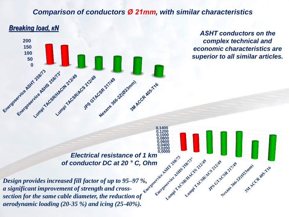
Comparison of conductors Ø 21mm, with similar characteristics.
working current load, A
Cost, EUR/км
0 10 000 20 000 30 000 40 000 50 0000 200 400 600 800 1 0001 200
Energoservice АSHТ 258/73
Energoservice АSHS 258/73*
Lumpi TACSR/HACIN 212/49
Lumpi TACSR/ACS 212/49
JPS GTACSR 217/49
Nexans 366-2Z(Ø23mm)
3M ACCR 405-T16
Low sag for high performance
ASHS and ASHТ conductors are
expand designing of HV power lines
and allow dealing with the goals that
used to be unpractical or used to
require great efforts and costs.
Tested in Germany for compliance with DIN EN 50540, DIN EN 62004, 48207, 62568,
IEC 61284, 61854, Cigré 426, DIN EN 62568, IEEE 1138
0
50
100
150
200
Comparison of conductors Ø 21mm, with similar characteristics
Breaking load, кN
0,00000,02000,04000,06000,08000,10000,12000,1400
Electrical resistance of 1 km
of conductor DC at 20 ° C, Ohm
ASHТ conductors on the
complex technical and
economic characteristics are
superior to all similar articles.
Design provides increased fill factor of up to 95–97 %,
a significant improvement of strength and cross-
section for the same cable diameter, the reduction of
aerodynamic loading (20-35 %) and icing (25-40%).

Comparison spans with new (ASHS/ASHT) and standard conductor.
Projects for OHL of different voltage classes
0
2
4
6
8
10
12
14
16
18
20
0 100 200 300 400
Spans, м
Standard St-AL120/19; ASHS 128/37
110kV
0
2
4
6
8
10
12
14
16
18
20
0 50 100 150 200 250 300 350Spans, m
Standard St-AL150/24; ASHS 128/37
110kV
Increase in the
span of 38%
Increase working
current
Resistance
reduction
Reduction of
diameter
220kV
Standard St-AL300/39 ASHS
317/47 277/79 371/106

Comparison of test pilot wire in Germany with wires used by TenneT and FDF
0
2
4
6
8
10
12
14
16
18
20
0 50 100 150 200 250 300 350 400
Spain, м
АСВТ 216/33 К 264-AL1/34-St1A Aster 228,0 AERO-Z 242-2Z АС 185/43 ACCR_405-T16 АНВП 240,72 6101 Т4-290
Section Al,
мм2
Resistance 20)С,
Ом/км
Current at nominal
mode at J=1,1 A/мм2,
А
Current
at 800С*
Current at
900С*
Current at
150°С*
ASHT 216/33 235,5 0,13 259,05 627 699 1010
264-AL1/34-St1A 263,7 0,1095 290,0 687
ANVP 240,72 6101 Т4-290 240,72 0,106 264,8 708
AERO-Z 242-2Z 241,98 0,139 266,2 610
ACCR 185/43 185,0 0,1559 203,5 589
ACCR_405-T16 205,0 0,146 225,5 1100
Aster 228,0 288,34 0,115 317,2
Given the difference of aluminum sections of our products are comparable or superior to counterparts in the EEC

Span length with allowable сlearance spans for OHL in EU
400 кВ
Icc 1080А 1098А 1283А 1397А 1300А
220 kV
Icc 802А 809А 981А 960А
220kV 220kV
Icc 687А 776А 1129А* 837А 978А* 658

Additional economic benefit due to high breaking
strength: decrease in the number of supports and reduce sag;
the reduce level of internal corrosion in the conductor;
the intensity of the formation of ice due to the surface shape;
the reduce amplitude of pitching conductors.
Significantly lower operating elongation
The application of plastic compression ASHS or ASHT conductors
makes it possible to reduce the wind load by 10-26% compared to
conventional wires with similar values of the area of aluminum layers.
In case of application for repair/upgrading works at the old OHL, new
conductors in high-temperature execution are optimum, especially
considering their rather low cost.
Practically standard fittings
By results of the conducted comparative
researches of conductors of identical diameter
critical corona voltage for ASHS/ASHT Increase
relative to the standard steel-Aluminum Wire.
In the same time the corona-induced acoustic
noise are reduction.

Same diameter 18.8 mm ASHS 197/55 conductor by
“Energoservice", has corona discharge voltage by 5.7%
higher than ACSR 185/29
Similar tests were carried out for
ASHS 216/33 Ø18,5 - Ø21,6 ACSR 240/32
have the same corona discharge voltage.
Corona-induced acoustic
noise are reduction.
wind loads reduction;
less susceptibility to conductor
galloping and vibrations self-extinction

The application of plastic compression products makes it possible to reduce the wind load.
Our conductors having streamlined design is lower by 33% on the average. Reduction of wind load makes it possible to reduce the load on power transmission poles and to mount
conductors with greater weight (which more than compensated) on existing towers during capital repairs.
Also, the possibility to reduce the load on all elements of overhead line when keeping its transmission capacity
appears.
The wind load acting on the conductor across the center was calculated as
the sum of pressure X-components: F = ∫n • P dl, where P is pressure, n is the
unit vector along the X-axis. The interactions of wind and conductors depending
on wind speed and type of conductor’s cross-section have been compared.
The following conductors with similar diameters and cross-section area
have been used for comparison. The calculated wind load differs from
P(H/W), standard wind load on conductors and ground wires, determined
according to 7-th edition of Electrical Installations Code. The difference
takes place due to ignoring the following facts: wind pressure change
at various heights depending on terrain, the influence of span length
on the wind load, wind pressure non-uniformity along overhead line span.
The used approach allows engineers to determine clearly the contribution
of conductor’s contour to the change of wind load. The view of conductors' contour after crimping was
obtained by modeling steel-aluminum conductor plastic deformation process in the Abaqus/Explicit module of
the SIMULIA/Abaqus software (Abaqus, Inc., USA). For all our conductors of outer layer are tightly adjacent
to each other without gaps. It provides a possibility to simulate the wind impact on a single conductor with
one external contour by means of COMSOLMultiphysics. The wind pressure acting on the conductors and air
velocity distribution after flowing around ACSR conductors and our conductors are shown in Figures 3 and 4.
A smoother contour and the smaller diameter of our conductors provide the reduction of pressure zone in
front of the conductor (Figure 3b) and the stagnant zone behind it (Figure 4b). The maximum pressure on our
conductors is less by 3.5%, while the area with increased pressure is smaller regarding to ACSR conductors or
ground wires. The formation of several local areas characterized by air deceleration and reduced pressure is
much more visible on the protruding turns of ACSR aluminum wires facing airflow front.
FIG. 3
FIG. 4

A significant reduction lengthening in operating
drawing plastically deformed conductors are
confirmed by series of experiments.
The correct definition of the conductors creep has
recently become one of the important requirements
arising from the Exploitation organizations, as it
turned out that the capacity of many of the overhead
Lines may not be fully utilized due to increased, after
many years of service, sag of the conductors
Stretching ASHS / ACHT (shaded area). Results for
ASVP / ACBT (replacing the signs) and AC conductors
(delta) are reproduced on the basis of experiments.
Almost all the exploitation parameters of the new conductors
important for the OHL designer do exceed greatly than those for
ordinary ones, for a very moderate added cost.
The new conductors are excellent for new construction in
regions with excessive wind/ice loads or for extended transition.
In case of application for repair/upgrading works at the old
OHL, new conductors in high-temperature execution are
optimum, especially considering their rather low cost.
In constructing the ring network circuits and network with the
possibility of congestion during the post-emergency modes
The most effective integrated use ACHS/ACHT together with
Ground-wire cables (OPGW) possessing similar mechanical
characteristics.

Comparison of ASHS and ASHT characteristics with
standard conductor Ø 17,1mm An important task is: to identify where the use of new conductors will be most effective
Parameters of the conductors to be compared ACSR 150/24 ASHS, ASHT 162/47
value value Change in percent to ACSR
Core cross section, mm2 24,2 47,3 +90
Alum cross section, mm2 149 162,3 +8,9
Diameter, mm 17,1 17,1 0,0
Rated Breaking strength, daN 5227,9 9882,4 +89,0
Max current load, A 554 590,5 (822) + 6,6 (+ 48,4)
Span length of OHL at one and the same sag, m 280 364 + 30
Towers on the 10 km of OHL 37 27 - 27
Specific losses of electricity at the same current load (150 A), MWh/km per year 41,7 36,4 - 12,7
Conductor temperature expansion coefficient, 10-6 1/ °C 19,2 16,7 - 13
Conductor elasticity modulus, Е*10-3, N/mm2 82,5 88 + 6,7
Sag at the highest air temperature (+40 °С), m, for the spans:250 m
300 m
6,29
9,26
3,32
4,87 - 47,2
Sag at ambient temperature - 5 ° C in the 3rd region of the wind and ice
load, m:250/300
6,66
9,63
4,41
6,04 - 33,8
The electric field of the corona onset at dry weather, kV/cm 34,04 40,0 +17,5
DC Resistance (20 0C), Ohm/km 0,2039 0,1780 -12,7
Assessment of the relative costs 100 % 100-120 %

Our conductors don't demand difficult and expensive fittings.
The “conductor-fittings” systems have passed a series of tests in
accordance with the rules of PJSC “Rosseti”.
The types of fittings, with which conductors were tested
The pressed fittings
The Spiral fittings
Also vibration quenchers are developed

The operational stretching of conductors - one of
the most important requirements for the overhead
lines. Reducing of extraction plastically deformed,
galvanized OPGW, confirmed experimentally.
0,0
1
0,0
2
0,0
4
0,0
6
1 102
104 T i m e e l a p s e d , h o u r s
Rela
tive
e
lon
ga
tio
n,
%
Ground-wire cable & OPGW
The plastically deformed galvanized ground conductor resistant to
to lightning strikes with charges 147 ampere-second, and following
vibration exposure 10⁸. After testing, the breaking strength was
100% of it’s initial value. The tests were carried out several times
with same result.
The product plated by aluminum has lost mechanical durability
after exposure to lighting 85 KL; its actual strength during the
test reduced to 32.8 kN (49.6 % of the nominal breaking load).
Optimum integrated use of our wires and our ground wire,
taking into account the comparability of mechanical
characteristics.
The adequacy of the test and parameters for requirements (DIN &
IEC), confirmed by SAG Deutschland - Versuchs- und
Technologiezentrum

≠
≠ Cable barriers