energy and economic analysis of an...
TRANSCRIPT
1
ENERGY AND ECONOMIC ANALYSIS OF AN AUDITORIUM’S AIR CONDITIONING
SYSTEM WITH HEAT RECOVERY IN VARIOUS CLIMATIC ZONES
Konstantinos T. PAPAKOSTAS*, Ioannis TIGANITIS, and Agis M. PAPADOPOULOS
Aristotle University of Thessaloniki, School of Engineering, Department of Mechanical Engineering,
Thessaloniki, Greece, *Corresponding author, email: [email protected]
In many Heating, Ventilation and Air-Conditioning (HVAC) applications,
heat recovery (HR) devices are installed, aiming at reducing energy
consumption. Especially in buildings requiring a high percentage of outside
air for ventilation, there is a high potential for HR from exhaust air.
Climatic conditions are an important parameter which affects the recovered
heat and the payback period of the HR device. In this paper, a 250 person
auditorium is used as a model to estimate the applicability of an air-to-air
fixed-plate heat exchanger installed in the air handling unit (AHU) of the
HVAC system. The application is considered for four cities, representative of
climatic zones A, B, C, D of Greece, which also represent typical
Mediterranean climate conditions. Zone A, Crete and Southern Greece, is
similar to Nicosia (Cyprus) and Palermo (Sicily), Zone B, with Athens,
corresponds to Rome (Italy) and coastal Spain, Zone C with Thessaloniki is
similar to the Toulon (France) and Split (Croatia) and Zone D, with its
continental climate is more like Milano (Italy) and Lyon (France). An energy
analysis with the modified bin method energy calculation was performed to
calculate (i) the heating and cooling energy that can be recovered, (ii) the
reduction in HVAC equipment, and (iii) the expected payback period. For
the specific climatic conditions examined, it was proven that: heating energy
consumption decreased by 31 to 40%, depending on occupancy, while
electric energy consumption didn’t change notably; the payback period does
not exceed 24months, depending on climate zone and occupancy.
Key words: HVAC systems, heat recovery, air-to-air heat exchangers,
energy analysis, modified bin method
1. Introduction
The prime focus of HVAC systems in comfort applications is the control of temperature and
humidity in occupied spaces and the supply of adequate ventilation, in order to create a comfortable
and healthy indoor environment. The HVAC system typically accounts for much of the energy
consumed in a building in the form of heat or electricity, for the operation of chillers, heat pumps,
boilers, fans, pumps, and control devices. In ventilation systems serving spaces with high minimum
requirements for outdoor airflow (for example, densely occupied spaces), the energy consumption for
the outdoor fresh air treatment is usually high, while the exhaust air carries away a large fraction of the
energy that is consumed. By recapturing the energy from the exhausted air, that would otherwise be
lost, and by using it to precondition the incoming outdoor air the energy waste can be substantially

2
reduced. Outdoor air preconditioning is the process of cooling, dehumidifying, heating and/or
humidifying the entering outdoor air to approximately indoor temperature and humidity conditions.
With the application of HR technology for preconditioning the outdoor ventilation air, the air-
conditioning and heating equipment can be downsized considerably and the energy consumed can be
notably decreased.
There are several types of HR devices which are used for transferring energy from the exhaust
air to the supply air or vice versa. Generally, they can be divided into two main categories: i) the
sensible energy recovery devices, which transfer only sensible heat, and ii) the total energy (sensible
and latent) recovery devices, which transfer both sensible heat and moisture between the outdoor and
the exhaust air. The first category includes fixed-plate heat exchangers, heat pipes, aqueous glycol coil
loops, and sensible energy wheels; the most common example of the latter is the total energy rotary
wheel. All these devices are usually incorporated in ventilation or air-handling units that take in
outdoor air while venting indoor air. Exhaust air from the building interior passes through one side of
the HR device while the incoming makeup air passes through the other side.
Total energy recovery devices transfer both sensible heat and moisture. During the cooling
period the outdoor air is precooled and dehumidified. The transfer of heat and moisture is reversed
during the heating season, namely the outdoor air is preheated and prehumidified by removing both
sensible heat and moisture from the exhaust air stream and releasing it into the supply air stream.
Sensible energy devices transfer only sensible heat and no moisture is recovered. The indoor air
simply precools the incoming outdoor air during the cooling season while during the heating season
heat is transferred from the warmer indoor air to preheat the incoming outdoor air. An analytical
comparison of the characteristics, performance factors, advantages and use limitations of HR devices
are given in [1-2]. Mardiana-Idayu and Riffat [3] and Cuce and Riffat [4] present detailed reviews of
heat recovery systems and technologies for building applications.
Contemporary, well designed HVAC systems usually integrate one or more HR devices. Air-
to-air, fixed-plate, cross-flow heat exchangers are the most common into processing the supply air,
mostly because of their low cost and ease of installation. Cost and energy savings typically determine
which type of HR device best suits a particular application. The potential benefits depend mainly on
the ventilation airflow requirements, the climatic parameters, the effectiveness of the HE, and the
duration of the HVAC system’s operation.
A series of studies has been conducted to determine the applicability and the benefits of HR
systems, and their impact on the building’s energy performance. Fehrm et al [5] showed that HR is a
necessity in northern and central European climatic conditions and concluded that primary energy
consumption can be reduced by a minimum of 20% in Germany and Sweden. Besant and Simonson
[6] calculated the energy recovered and the annual savings, by installing an air-to-air sensible HE in
the HVAC system of a building. Lazzarin and Gasparella [7] evaluated heat recovery ventilation
(HRV) systems in three cities with different climates in Italy by taking into account the recovered
energy, the reduction in heating and cooling capacity, and the operation time of the systems. They
concluded that the payback period is related to the climate and to the heat recovery system’s
characteristics.
Zhong and Kang [8] investigated the applicability of air-to-air heat recovery systems in four
different climates in China and showed that the selection of the type of heat recovery system and its
3
efficiency is strongly related to the climate. Other studies [9-11] focused on the significant impact of
the climate conditions on the energy savings achieved by HR systems.
The scope of this paper is to calculate (i) the heating and cooling energy that can be recovered,
(ii) the reduction in cooling and heating equipment capacity, and (iii) the expected payback period
from the installation of an air-to-air fixed-plate cross-flow heat exchanger in a HVAC system. The
application is considered for four cities, representative of climatic zones A, B, C, D of Greece, which
also represent typical Mediterranean climate conditions. A university auditorium is used as a model in
order to calculate the expected energy and cost benefits from the installation of such a heat exchanger.
The modified bin method [12] was used for the energy analysis and a spreadsheet program was
constructed specially for this purpose. Energy calculations were performed both as with and without
the HE, and with full or half occupancy. The energy consumption, the installation and the operating
energy costs of the HVAC system were evaluated and compared, and the expected payback period was
computed. The effects of the capacity and size of primary and secondary heating and cooling
equipment were also examined.
2. Description of the conditioned space and HVAC system
The space under consideration is a 250-seat university auditorium, located at the ground floor
of a 5 storied office building and is used mostly for classes and lectures from 9 a.m. to 9 p.m., during
the working days of the week. The auditorium is conditioned by a single-duct, single-zone, constant
volume, all-air HVAC system, which is the most appropriate for a single room of this size, with
uniform load behavior and considerable ventilation air needs. The HVAC system consists of an air-
handling unit (AHU), the air duct distribution system, an electrically driven chiller, a gas boiler, a
humidifier, the piping network, and the control system. The general layout of the system’s component
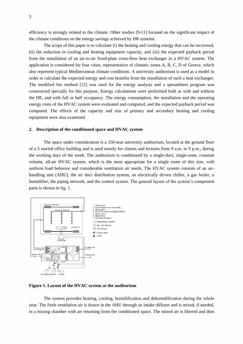
parts is shown in fig. 1.
Figure 1. Layout of the HVAC system at the auditorium
The system provides heating, cooling, humidification and dehumidification during the whole
year. The fresh ventilation air is drawn in the AHU through an intake diffuser and is mixed, if needed,
in a mixing chamber with air returning from the conditioned space. The mixed air is filtered and then

4
conditioned to the desired inside conditions. If the system is in the cooling mode, the air is cooled and
dehumidified before entering the space, while in the heating mode it is heated and humidified, at a
suitable temperature and moisture content. By installing an air-to-air heat exchanger in the AHU, the
exhaust and the fresh outdoor airstreams are passing through the HE, before leaving/entering the
mixing box respectively, as it is shown in fig. 1. In this case, the incoming outside air is precooled
(during cooling season) or preheated (during heating season) by the exhaust airstream, achieving a
reduction of the sensible portion of the ventilation air cooling and heating loads.
A gas boiler supplies hot water to the heating coil, a chiller supplies cold water to the cooling
coil, and a steam humidifier discharges steam into the conditioned air. The supply air, after being
properly processed in the AHU, it is transported through the supply fan and the supply air duct
network, to the auditorium room. The return air is driven back to the AHU with the return fan, through
the return air duct network. Since the space load varies as a function of time and occupancy, varying
amounts of heating or cooling energy are needed to match the heating and cooling load.
3. The control system
The size and capacity of HVAC systems are typically calculated with design conditions.
Nevertheless, full load conditions occur only during a rather small fraction of the operational hours
whilst partial load/occupancy conditions are the rule. The control system regulates the operation of the
HVAC system and enables its response according to changes in load and ventilation needs, so as to
preserve a good indoor air quality and maintain thermal comfort conditions, with efficient plant
operation and reduced energy use. The control system of the auditorium’s HVAC plant is equipped
with sensors for room air temperature, humidity and CO2 concentration, connected to a central
controller. The latter regulates the position of three-way valves, installed at the heating and cooling
coils, the steam flow from the humidifier, and the position of the dampers at the mixing box. In this
way, at part load/occupancy conditions, only the appropriate amounts of energy and ventilation air are
supplied. Fresh outdoor, and consequently exhaust, airflow, are regulated according to occupancy.
Under normal operation, these two airstreams pass through the air-to-air HE. In the cooling season,
when the temperature of outdoor air falls between the exhaust air temperature and the indoor discharge
air temperature, the system operates with the economizer cycle. The two airstreams - exhaust and
outdoor – instead of crossing the HE they pass through the by-pass dampers of the mixing box. This
function prevents the adding of heat to the outdoor fresh air, and accordingly to the cooling coil, and
reduces the ventilation load and the running time of cooling equipment.
4. The HVAC system design criteria
The heating and cooling loads of the room were calculated according to the methods described
in [13,14]. Outdoor-indoor design parameters, namely dry-bulb (DB) temperature, wet-bulb (WB)
temperature, relative humidity (RH) plus ventilation airflow requirements were adjusted according to
national technical directives and codes [15,16], and are given in tab.1. Climate conditions of zones A,
B, C, D [17] correspond to the Greek cities Heraklion, Athens, Thessaloniki and Florina respectively.
The climate in Greece is typical of the Mediterranean climate, characterized for the most part by mild
to cool wet winters and warm to hot dry summers. It varies from the hot/warm temperate dry of South

5
and East Greece (zones A and B) to the cool/cold temperate wet climate of Northern and Western
Greece (zones C and D). A great variety of climate subtypes, always within the Mediterranean climate
frame, are encountered in several regions of Greece due to the influence of topography; the many
hours of sunshine are their common feature. The vast majority of the country is classified Csa at the
Koeppen scale, although some mountainous areas are Dwb or Dwf.
Table 1. HVAC system design criteria
Climate zone
A B C D
Number of people at full occupancy 250
Outdoor air required [15] 8 L/s.person
Room DB temperature
(Summer/Winter) [15] 26ºC/22ºC
Room RH (Summer/Winter) [15] 50/40%
Indoor DB/WB design conditions
(Summer) [16] 32.5ºC/23 ºC 35.5ºC/22ºC 35ºC/23ºC 33.5ºC/21ºC
Outdoor DB/WB design conditions
(Winter) [16] 7ºC/5ºC 3ºC/1ºC -2ºC/-3ºC -7ºC/-8ºC
From the design heating and cooling loads results, it is concluded that the load for cooling and
dehumidifying the outdoor air of ventilation is about the 50% of the total cooling load, with an
exception in zone D where it represents 30% of the total load (due to low temperatures during some
periods of the day during summer). The load for heating the outdoor ventilation air varies from 89% to
92% of the total heating load, for the four climate zones respectively. From these results it is presumed
that there is a great potential for energy savings by applying heat recovery in ventilation, especially
during the heating season.
The supply air flow rate of the system suQ [m-3s] is calculated with the following equation:
)(=
sur
srsuQ
t - tcρ
q (1)
where, rsq [W] is the space sensible design cooling load, ρ = 1.204 [kgm-3] – the density of standard
dry air, c = 103 [J.kg-1K-1] – the specific heat of dry air, sut [ºC] – the supply air temperature, and rt
[ºC] – the space DB temperature,
The required supply air flow rate, calculated according to eq. (1), is resulted in all four cities
less than the required ventilation rate with full occupancy, which is equal to 7200 [m3h-1], thus the
HVAC system operates with 100% outside air. During part load occupancy, a percentage of return air
is recirculated at the mixing box of the AHU and is mixed with the outdoor fresh air.
When no air-to-air HE is installed in the AHU, the temperature of the ventilation air entering
the mixing box is equal to the outdoor temperature. In the case of an air-to-air HE installation, with
only sensible heat recovery, the temperature of the outdoor ventilation air leaving the HE and entering
the mixing box is calculated according to the definition equation of the HE sensible effectiveness:
)(
)(=
)(
)(=
suieximin
exoexiex
suieximin
suisuosus t-tm
t-tm
t-tm
t-tmε (2)
6
where, sε is the sensible effectiveness of the air-to-air HE, sum [kgs-1] – the supply dry air mass flow
rate, exm [kgs-1] – the exhaust dry air mass flow rate, minm [kgs-1] – the smaller of sum and exm ,
ιsut [ºC] – the supply moist air entering temperature, suot [ºC] – the supply moist air leaving
temperature, exit [ºC] – the exhaust moist air entering temperature, exot [ºC] – the exhaust moist air
leaving temperature. Eq. (2) assumes state steady conditions; no heat transfer between the HE and its
surroundings, and no condensation or frost formation on heat exchanger surfaces. In this project the
effectiveness sε is taken equal to 0.50.
With the installation of the air-to-air heat exchanger in the AHU, the total cooling load
decreases from 10% to 15% and the total heating load is reduced by about 39% for all zones, with a
corresponding reduction in the required chiller and boiler capacity, and in the size and capacity of
water pumps. However, the static pressure drop of the system increases; so do consequently the
supply and return fan total pressure requirements. The magnitude of the pressure drop through the
device and the configuration of the fans determine how much additional energy is consumed. The
electrical input power of the supply and return fan is 1.2 and 0.65 kW without the air-to-air HE, while
it increases to 1.1 and 1.7 kW respectively, when the HE is installed. The extra pressure drop due to
the heat recovery device in the system is 200 Pa. The operating cost savings provided by recovered
energy must exceed the increased cost of operating the fans in order to offset the cost of the HR
device. A year-round energy analysis must be performed to determine the overall effect on the energy
consumption of the HVAC system.
5. Energy analysis
The energy analysis was performed by applying the modified bin energy calculation method,
which simulates the building loads and the operation of the primary and secondary equipment, and is
therefore often used for the evaluation of HR systems [12]. Besides being easy to apply, it takes into
account the frequency distribution of outside temperature and humidity, and hence the part load
performance of the system and the variations of the chiller energy efficiency ratio (EER) and
coefficient of performance (COP) during summer and winter operation. Bin weather data of the above
mentioned four Greek towns were taken from [18-20]. A spreadsheet program was developed and the
energy requirements of the auditorium, along with the energy consumption of the HVAC equipment,
were calculated for the following cases:
a) Full occupancy – without air-to-air heat recovery
b) Full occupancy – with air-to-air heat recovery
c) Half occupancy – without air-to-air heat recovery
d) Half occupancy – with air-to-air heat recovery
Calculations were performed for every month of the year, for all those cases and all climate
zones. For reasons of brevity, only the total annual results are presented in this paper. The electric
energy consumption [kWhel] of chiller, fans, pumps and humidifier along with the boiler’s thermal
energy consumption [kWhth], during the cooling and heating period were calculated for each of the
above mentioned four cases and are shown in Tab. 2, 3, 4 and 5. In the case of full occupancy (tab. 2
and 3) the air-to-air heat recovery HE saves about 40% of the heating energy required for the
operation of the system, in all zones (Fig. 1). Total annual electric energy consumption decreases by
1.7, 2.8 and 0.2%, for the zones A, B, C respectively, and only in zone D it increases by 4.5% (Fig. 2).

7
Table 2. Energy consumption results without air-to-air HE - full occupancy (250 persons)
Equipment energy
consumption Climate zone
A B C D A B C D
Cooling period Heating period
Chiller [MWhel] 17.57 14.86 13.70 5.03
Boiler [kWhth] 30.42 49.17 64.76 90.81
Supply fan [MWhel] 2.10 2.13 2.12 2.06 1.40 2.01 2.36 2.68
Return fan [MWhel] 1.26 1.28 1.27 1.24 0.84 1.24 1.40 1.61
Water pumps [MWhel] 0.24 0.24 0.24 0.23 0.07 0.10 0.11 0.13
Humidifier [MWhel] 1.28 2.36 5.85 12.81
Total electric energy
[MWhel] 21.17 18.51 17.33 8.56 3.59 5.71 9.72 17.23
Total thermal energy
[MWhth] 30.42 49.17 64.76 90.81
The chiller’s electrical energy consumption is reduced in all zones by 2.2%-12%, depending
on the zone, but the installation of the HE increases the pressure drop in the AHU and leads to a 16%
increase of the energy consumption by the fans. In zones A, B and C this increase is offset by the
decrease in chiller’s energy demand but in zone D the reduction of chiller energy consumption is less
than the increase of energy consumed by the fans.
Table 3. Energy consumption results with air-to-air HE - full occupancy (250 persons)
Equipment energy
consumption Climate zone
A B C D A B C D
Cooling period Heating period
Chiller [MWhel] 16.22 13.07 12.46 4.92
Boiler [kWhth] 18.31 29.39 38.44 53.40
Supply fan [MWhel] 2.38 2.41 2.40 2.34 1.59 2.34 2.65 3.03
Return fan [MWhel] 1.54 1.56 1.55 1.51 1.03 1.51 1.71 1.96
Water pumps [MWhel] 0.24 0.24 0.24 0.23 0.07 0.10 0.11 0.13
Humidifier [MWhel] 1.28 2.36 5.85 12.81
Total electric energy
[MWhel] 20.38 17.28 16.65 9.00 3.97 6.31 10.32 17.93
Total thermal energy
[MWhth] 18.31 29.39 38.44 53.40
When the system operates without the HE, the chiller consumes 71%, 61%, 51% and 20% of
the total electric energy, while the fans and pumps 24%, 29%, 28% and 31%, in zone A, B, C and D
respectively. The rest is consumed by the humidifier. When an air-to-air HE is installed the chiller
8
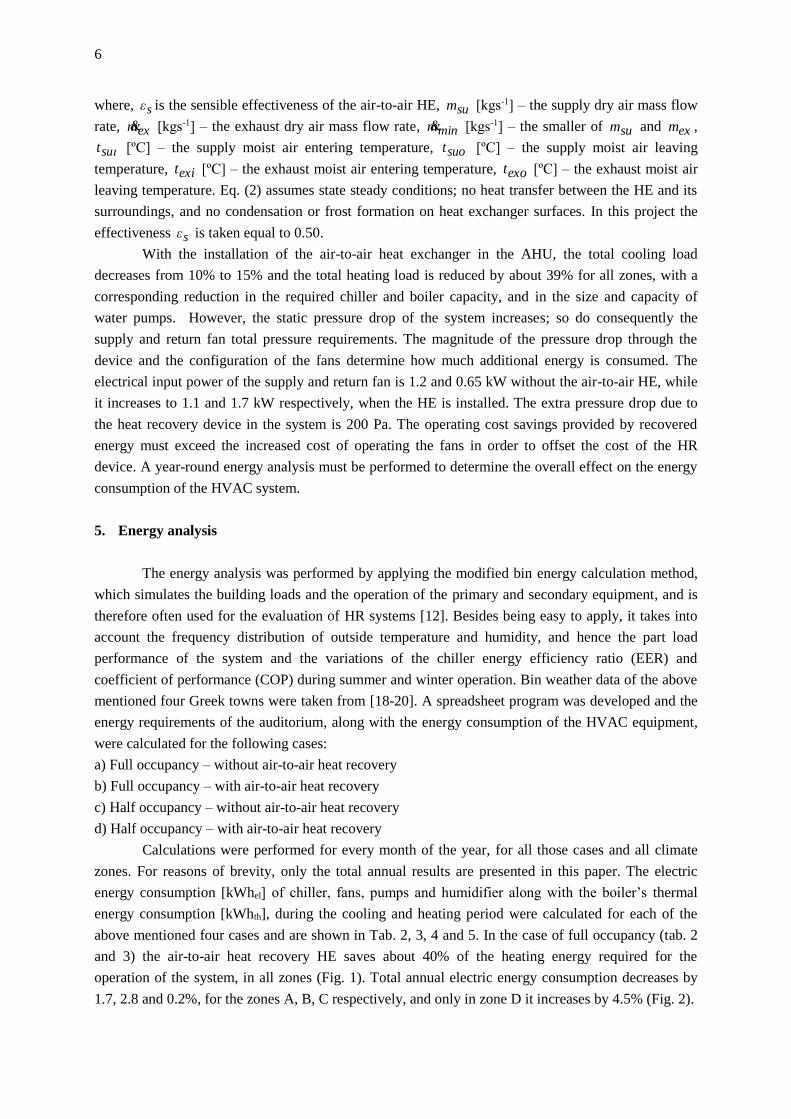
consumes 66%, 55%, 46% and 18% of the total electric energy on annual basis, while the fans and
pumps 28%, 35%, 32% and 34%, in zone A, B, C and D respectively.
Table 4. Energy consumption results without air-to-air HE – half occupancy (125 persons)
Equipment energy
consumption Climate zone
A B C D A B C D
Cooling period Heating period
Chiller [MWhel] 14.63 14.14 12.20 4.48
Boiler [kWhth] 20.00 31.97 41.86 57.23
Supply fan [MWhel] 2.10 2.13 2.12 2.06 1.40 2.06 2.34 2.68
Return fan [MWhel] 1.26 1.28 1.27 1.24 0.84 1.24 1.40 1.61
Water pumps [MWhel] 0.24 0.24 0.24 0.23 0.07 0.10 0.11 0.13
Humidifier [MWhel] 0.64 1.18 2.93 6.39
Total electric energy
[MWhel] 18.23 17.79 15.83 8.01 2.95 4.58 6.77 10.81
Total thermal energy
[MWhth] 20.00 31.97 41.86 57.23
In the case of half occupancy (Tab. 4 and 5) the heat recovery device reduces the heating
energy about 31%, in all zones (Fig. 1). Τhe total annual electric energy consumption is increased in
all zones, and more specifically by 1.4, 0.7, 2.2 and 6.7%, for the zones A, B, C and D respectively.
The chiller’s electric energy consumption remains the same in zone D and decreases by 4.4%-6.9%, in
zones A, B and C (Fig. 2).
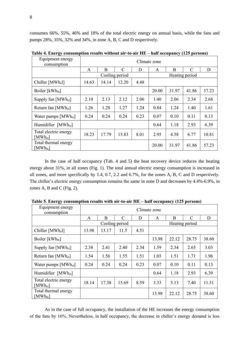
Table 5. Energy consumption results with air-to-air HE – half occupancy (125 persons)
Equipment energy
consumption Climate zone
A B C D A B C D
Cooling period Heating period
Chiller [MWhel] 13.98 13.17 11.5 4.51
Boiler [kWhth] 13.98 22.12 28.75 38.60
Supply fan [MWhel] 2.38 2.41 2.40 2.34 1.59 2.34 2.65 3.03
Return fan [MWhel] 1.54 1.56 1.55 1.51 1.03 1.51 1.71 1.96
Water pumps [MWhel] 0.24 0.24 0.24 0.23 0.07 0.10 0.11 0.13
Humidifier [MWhel] 0.64 1.18 2.93 6.39
Total electric energy
[MWhel] 18.14 17.38 15.69 8.59 3.33 5.13 7.40 11.51
Total thermal energy
[MWhth] 13.98 22.12 28.75 38.60
As in the case of full occupancy, the installation of the HE increases the energy consumption
of the fans by 16%. Nevertheless, in half occupancy, the decrease in chiller’s energy demand is less

9
than the increase of energy consumed by the fans, resulting in the increase of the total electric energy
consumption. Without the HE, the chiller consumes 69%, 63%, 54% and 24% of the total electrical
energy, while the fans and pumps 28%, 31%, 33% and 42%, in zone A, B, C and D respectively. The
rest is consumed by the humidifier. When an air-to-air HE is installed the chiller consumes 65%, 58%,
50% and 22% of the total electric energy on annual basis, while the fans and pumps 32%, 36%, 37%
and 46%, in zone A, B, C and D respectively.
Figure 2. Annual electric energy consumption of the HVAC system
Figure 3. Annual thermal energy consumption of the HVAC system
Therefore, both in the case of full and half occupancy, the installation of the air-to-air HE
reduces significantly the heating energy consumption (Fig. 3). The electrical energy consumption for
cooling is generally decreased, with a gradual reduction from cold to warm climate zones. The electric
energy consumption for humidifying, on the contrary, progressively increases from dry and warm (A
and B) to wet and cold zones (C and D). The installation of the heat recovery HE reduces the energy
consumption for heating, cooling, humidifying and dehumidifying, but electrical energy for fans is
raised. This increase affects the total electrical energy consumption of the system. An economic
analysis is therefore required to evaluate if the installation of the HE is beneficial.

10
6. The HVAC system design criteria
The reductions in energy use are linked to annual cost savings using actual energy cost data:
electricity costs 0.19 €/kWh and natural gas 0.070 €/kWh, which is average value of natural gas in
Athens and Thessaloniki (all rates at end 2016). Although the cities of Heraklion and Florina have no
gas network, for reasons of comparison it is assumed that the boilers are gas fired.
Table 6. Annual operating cost [€] and total cost savings [%]
Occupancy Full (250 persons) Half (125 persons)
Climate zone A B C D A B C D
Energy cost [€] - without air-to-air HE
Electric energy
(cooling) 4,021 3,518 3,292 1,627 3,462 3,381 3,007 1,523
Electric energy
(heating)] 682 1,093 1,842 3,271 560 868 1,258 2,052
Thermal energy
(heating) 2,129 3,442 4,534 6,357 1,401 2,238 2,930 4,006
Energy cost [€] - with air-to-air HE
Electric energy
(cooling) 3,871 3,284 3,165 1,710 3,446 3,304 2,983 1,632
Electric energy
(heating)] 753 1,198 1,960 3,387 631 973 1,405 2,188
Thermal energy
(heating) 1,282 2,058 2,691 3,758 978 1,548 2,013 2,702
Total Cost savings 926 1,514 1,852 2,400 368 662 795 1,059
Savings [%] 13.6 18.8 19.2 21.3 6.8 10.2 11.0 14.0
With these rates, the total annual energy cost is shown in tab. 6. In the case of full occupancy,
the installation of the HE reduces the yearly total energy cost by 13.6, 18.8, 19.2 and 21.3%, for the
climate zones A, B, C and D respectively. In the case of half occupancy the yearly total energy cost is
reduced by 6.8, 10.2, 11.0 and 14.0%, for climate zones A, B, C and D. These cost reductions are
mainly a consequence of the significant decrease in thermal energy operating cost. Namely, although
in some cases the electric energy cost increases, the installation of the HE is always beneficial for the
final total operating cost. If oil use is assumed instead of natural gas, the cost reduction is even greater
due to the higher price of oil (~0.1 €/kWh) and the higher percentage of thermal energy in the total
energy recovery. Energy savings and cost reduction must offset the cost of the HR device. The use of
air-to-air heat recovery usually permits a smaller heating and cooling plant, but it may lead to increase
in the fans’ motor size. In this project, the investment cost of HVAC system in the four cities, was
determined according to price lists of HVAC equipment dealers and installers in the Greek market.
The design configuration with heat recovery proved to be more expensive than the typical system with
no recovery in zones B, C and D, while in zone A, no extra investment is needed. With the use of
payback method the payback period was calculated. The results indicate that with full occupancy the
expected payback period is less than 1 year for all climate zones (1, 7, 4 and 10 months for climate
zones A, B, C and D). Even with half occupancy, the maximum payback period is less than 2 years (1,
17, 9 and 23 months for climate zones A, B, C and D).

11
These results refer to a continuous operation of the HVAC system from 9 a.m. to 9 p.m. and
during all working days (Monday to Friday). With occupancies between 50% and 100%, the expected
payback period is in all cases between 1 and 24 months, according to climate zone and occupancy rate.
Also, when oil is used in zone D the payback period further decreases. There are also the uncertainties
of future energy prices, which may prolong or shorten this period. In a recent research [21] it was
concluded that the payback period of a sensible recovery HE, in 24-hour operating ventilation systems,
is less than 4 months in Mediterranean countries. Any increase in electricity price by 10% reduces the
cost savings rate by 5% in the case of full occupancy and by about 8% in the case of half occupancy.
Nevertheless, the total cost savings and the expected payback period are not considerably affected. If a
HE with higher effectiveness sε is chosen, the increased effectiveness must be valuated against the
increased initial cost.
7. Conclusions
The research discussed on this paper covers the energy and economic analysis of an air-
conditioning system for a university auditorium that utilizes sensible heat recovery, in various
Mediterranean climate conditions. Four Greek cities were selected, representing the four climate zones
of Greece which correspond well to cities in Mediterranean countries like Cyprus, Croatia, Italy and
France: two of them have hot/warm temperate dry climate, and the other two cool/cold temperate wet
climate conditions. As it was proven, the installation of an air-to-air sensible heat exchanger is a cost-
effective way of pre-conditioning outside ventilation air, for all climatic conditions and both for full
and half occupancy patterns. The annual total energy cost is reduced by 6.8 to 21.3% according to
occupancy and climate zone, with a progressive rate from warm to cold climate conditions mostly due
to the significant reduction of the thermal energy cost, while the energy cost for cooling is not notably
reduced. The payback period of the extra investment for the HR device does not exceed 24 months,
depending on climate zone and on whether the system operates at full, intermediate or half occupancy.
The findings discussed in this paper on the one hand confirm the results of previous studies
and on the other underline the necessity to thoroughly consider the impact of the heat recovery
systems with respect to partial load conditions and varying energy prices. In that sense, further
investigation is needed in order to examine if the installation of other types of energy recovery devices
is beneficial, and on how the feasibility is influenced, when the HVAC systems operate with less than
100% outside air and for varying hours during the day. It is a research that is worth carrying out,
because HVAC systems of this type and size are common and widespread. They can be found from
universities’ auditoria to cinema halls and from events’ halls in hotels to restaurants and bars. It is
therefore clear, that they present a well suited and feasible case for the application of waste heat
recovery technologies, as part of an energy renovation strategy to improve the efficiency of existing
buildings, while moving towards the Nearly Zero Energy Building.
References
[1] ***, ASHRAE, Chap. 44 – Air-to-Air Energy Recovery, in: 2004 ASHRAE Handbook – HVAC
Systems and Equipment, American Society of Heating, Refrigerating, and Air-Conditioning
Engineers, Inc., Atlanta Geo., USA, 2008, pp. 25.1-25.25
[2] Besant, R., Simonson, C., Air-to-Air Exchangers, ASHRAE Journal, 45 (2003), 4, pp. 42–50
12
[3] Mardiana-Idayu, A., Riffat, S.B., Review on Heat Recovery Technologies for Building
Applications, Renewable and Sustainable Energy Reviews, 16 (2012), pp. 1241-1255
[4] Cuce, P.M., Riffat, S.B., A Comprehensive Review of Heat Recovery Systems for Building
Applications, Renewable and Sustainable Energy Reviews, 47 (2015), pp. 665-682
[5] Fehrm, M., et al., Exhaust Air Heat Recovery in Buildings, International Journal of
Refrigeration, 25 (2002), pp. 439–449
[6] Besant, R.W., Simonson, C.J., Air-to-Air Energy Recovery, ASHRAE Journal, 42 (2000), 4, pp.
31–38
[7] Lazzarin, R.M., Gasparella A., Technical and Economical Analysis of Heat Recovery in Building
Ventilation Systems, Applied Thermal Engineering, 18 (1998), 1-2, pp. 47-67
[8] Zhong, K., Kang Y., Applicability of Air-to-Air Heat Recovery Ventilators in China, Applied
Thermal Engineering, 29 (2009), pp. 830–840
[9] Zhou, Y.P., et al., Performance of energy recovery ventilator with various weathers and
temperature set-points, Energy and Buildings, 39 (2007), 12, pp. 1202–1210
[10] Kang, Y., et al., Temperature Ranges of the Application of Air-to-Air Heat Recovery Ventilator
in Supermarkets in Winter, China, Energy and Buildings, 42 (2010), 12, pp. 2289–2295
[11] Liu, J., et al., Efficiency of Energy Recovery Ventilator with Various Weathers and Its Energy
Saving Performance in a Residential Apartment, Energy and Buildings 42 (2010), 1, pp. 43–49
[12] Knebel, D., Simplified energy analysis using the modified bin method, American Society of
Heating Refrigerating and Air-Conditioning Engineers, Inc., Atlanta Geo., USA, 1983
[13] ***, ASHRAE, Chap. 25 – Heating Load, in: 1985 ASHRAE Handbook – Fundamentals,
American Society of Heating, Refrigerating, and Air-Conditioning Engineers, Inc., Heating load,
Atlanta Geo., USA, 1985, pp. 25.1-25.10
[14] ***, ASHRAE, Chap. 25 – Air-Conditioning Cooling Load, in: 1985 ASHRAE Handbook –
Fundamentals, American Society of Heating, Refrigerating, and Air-Conditioning Engineers,
Inc., Air conditioning Load, Atlanta Geo., USA, 1985, pp. 26.1-26.42
[15] ***, Technical Directive of the Technical Chamber of Greece 2425/86, Building installations:
Data for calculation air-conditioning loads in building spaces (in Greek), Technical Chamber of
Greece, Athens, Greece, 1987
[16] ***, Technical Directive of the Technical Chamber of Greece 20701-3/2010, Climatic data of
Greek regions (in Greek), Technical Chamber of Greece, Athens, Greece, 2012
[17] ***, Official Government Gazette EK407/B/9.4.2010, Regulation on Energy Performance in the
Building Sector – KENAK (in Greek), Ministry of Environment Energy and Climate Change,
Greece, 2010
[18] Karadaglis, C., Felekis P., Estimation of bin temperature data in 38 Greek cities (in Greek),
Diploma thesis, Department of Mechanical Engineering, Aristotle University Thessaloniki,
Thessaloniki, 2006
[19] Papakostas, K., et al., Bin Weather Data for 38 Greek Cities, Applied Energy, 85 (2008), pp.
1015–1025
[20] Zagana Papavasileiou, P., Updating of temperature database of Athens and Thessaloniki for
energy studies: Period 1983-2012 (in Greek), Diploma thesis, Department of Mechanical
Engineering, Aristotle University Thessaloniki, Thessaloniki, 2013

13
[21] Tafelmeier, S., et al., Annual Performance of Sensible and Total Heat Recovery in Ventilation
Systems: Humidity Control Constraints for European Climates, Buildings, 7 (2017), 28
doi:10.3390/buildings7020028