energy-efficient routing and secure communication in wireless sensor networks · pdf...
TRANSCRIPT

Energy-efficient Routing and SecureCommunication in Wireless Sensor Networks
A Thesis Submitted for the Degree of
Doctor of Philosophy
By
Mian Ahmad Jan
in
Faculty of Engineering and Information Technology
UNIVERSITY OF TECHNOLOGY, SYDNEY
AUSTRALIA
February 2016
c© Copyright by Mian Ahmad Jan, 2016

UNIVERSITY OF TECHNOLOGY, SYDNEY
Faculty of Engineering and Information Technology
The undersigned hereby certify that they have read this thesis entitled “Energy-efficient
Routing and Secure Communication in Wireless Sensor Networks” by Mian Ahmad
Jan and that in their opinion it is fully adequate, in scope and in quality, as a thesis for the
degree of Doctor of Philosophy.
Principal Supervisor Co-Supervisor
Dr. Priyadarsi Nanda Prof. Xiangjian He
ii

CERTIFICATE OF AUTHORSHIP
Date: 3rd February 2016
Author: Mian Ahmad Jan
Title: Energy-efficient Routing and Secure Communication in Wireless Sensor Networks
Degree: PhD
I certify that the work in this thesis has not previously been submitted for a degree nor
has it been submitted as part of requirements for a degree except as fully acknowledged
within the text.
I also certify that the thesis has been written by me. Any help that I have received in my
research work and the preparation of the thesis itself has been acknowledged. In addition,
I certify that all information sources and literature used are indicated in the thesis.
Signature of Author
iii

Acknowledgements
Firstly, I would like to express my sincere gratitude to my supervisor, Dr. Priyadarsi
Nanda whose expertise, understanding, and patience, added considerably to my graduate
experience. He is such a nice, generous, helpful and kind-hearted person. I am greatly
indebted to his continuous encouragement, advice, motivation and invaluable suggestions.
I owe my research achievements to his experienced supervision. His guidance helped
me all the time with my research and writing of this thesis. Without his support and
supervision, I could not have come this far. Besides my supervisor, I would like to thank
my co-supervisors, Prof. Xiangjian He and Dr. Ren Ping Liu for their valued suggestions
and constant support, and for the numerous conversations with them. Their encouragement
has kept me moving ahead at a critical time. Without their help, I would not have been able
to complete this thesis. I gratefully acknowledge the useful discussions with Dr. Zhiyuan
Tan, Mohammed Ambu Saidi, Thawatchai Chomsiri and Dr. Mahardhika Pratama. I wish
to thank my fellow research students and the staff of the school, especially those people
listed below for providing assistance for the completion of this research work.
• Hla Myint, M. Usman Khan, Adrian Johannes, Ashish Nanda, Amber Umair, Deepak
Puthal, Upasana Nagar, Doan B. Hoang, Soud Nassir, Mohammad Alshehri, Khaled
Aldebei, Minqi Li and Chi Yang.
I appreciate the financial support of University of Technology Sydney International
Research Scholarship (IRS) and a Top-up scholarship provided by the Commonwealth
Scientific and Industrial Research Organisation (CSIRO).
Last but not the least, I would like to express my love and gratitude to my family
members, especially my parents, my sister and my brother-in-law. Foremost, I want to
thank my late brother for his constant motivation during my studies. In my heart, you will
always stay loved and remembered, every day.
iv

Dedicated to my family
v
Table of Contents
Acknowledgements iv
List of Tables x
List of Figures xi
Abbreviation xv
Abstract xviii
List of Publications xx
1 Introduction 11.1 Background . . . . . . . . . . . . . . . . . . . . . . . . . . . . . . . . . 1
1.1.1 Routing Protocols in WSN . . . . . . . . . . . . . . . . . . . . . 4
1.1.2 Emergence of Internet of Things . . . . . . . . . . . . . . . . . . 7
1.1.3 Security Considerations . . . . . . . . . . . . . . . . . . . . . . 8
1.2 Motivation . . . . . . . . . . . . . . . . . . . . . . . . . . . . . . . . . . 10
1.3 Research Objectives and Contribution . . . . . . . . . . . . . . . . . . . 12
1.4 Research Focus . . . . . . . . . . . . . . . . . . . . . . . . . . . . . . . 15
1.5 Structure of the Thesis . . . . . . . . . . . . . . . . . . . . . . . . . . . 16
2 Literature Review 182.1 Overview of Wireless Sensor Network . . . . . . . . . . . . . . . . . . . 19
2.2 Hardware Components of a Node . . . . . . . . . . . . . . . . . . . . . . 22
vi

2.3 WSN Routing Protocols . . . . . . . . . . . . . . . . . . . . . . . . . . 26
2.4 Cluster-based Hierarchical Routing Protocols . . . . . . . . . . . . . . . 28
2.4.1 Types of Cluster-based Hierarchical Routing Protocols . . . . . . 28
2.4.2 Congestion Detection in Cluster-based Hierarchical Protocols . . 35
2.5 Sybil Attack Detection . . . . . . . . . . . . . . . . . . . . . . . . . . . 38
2.5.1 Detection of Sybil Attack in WSN . . . . . . . . . . . . . . . . . 38
2.5.2 Detection of Sybil attack in a Wildfire Monitoring Application . . 41
2.6 Internet of Things . . . . . . . . . . . . . . . . . . . . . . . . . . . . . . 44
2.6.1 Constrained Application Protocol . . . . . . . . . . . . . . . . . 48
2.6.2 Security Challenges in IoT . . . . . . . . . . . . . . . . . . . . . 51
2.7 Summary . . . . . . . . . . . . . . . . . . . . . . . . . . . . . . . . . . 55
3 Energy-efficient Communication in Cluster-based Hierarchical Networks 573.1 Energy-efficient Cluster-based Routing Algorithm . . . . . . . . . . . . . 57
3.1.1 Network Architectural Model . . . . . . . . . . . . . . . . . . . 58
3.1.2 Network Operational Model . . . . . . . . . . . . . . . . . . . . 60
3.1.3 Experimental Results and Analysis . . . . . . . . . . . . . . . . 62
3.1.3.1 Lifetime of the Network . . . . . . . . . . . . . . . . . 63
3.1.3.2 Data Aggregation . . . . . . . . . . . . . . . . . . . . 64
3.1.3.3 Quality of Data . . . . . . . . . . . . . . . . . . . . . 65
3.2 A Centralized Energy Evaluation Model . . . . . . . . . . . . . . . . . . 66
3.2.1 Network Operational Model . . . . . . . . . . . . . . . . . . . . 67
3.2.2 Energy Evaluation Model . . . . . . . . . . . . . . . . . . . . . 73
3.3 Summary . . . . . . . . . . . . . . . . . . . . . . . . . . . . . . . . . . 77
4 Energy-efficient Cluster-based Congestion Control Algorithm 794.1 The PASCCC Protocol . . . . . . . . . . . . . . . . . . . . . . . . . . . 80
4.2 Framework of PASCCC . . . . . . . . . . . . . . . . . . . . . . . . . . . 81
4.3 PASCCC Operational Mechanism . . . . . . . . . . . . . . . . . . . . . 82
4.3.1 PASCCC: An Application-specific Protocol . . . . . . . . . . . . 82
4.3.2 PASCCC: Congestion Detection and Mitigation . . . . . . . . . . 84
4.3.3 PASCCC: Queuing Model . . . . . . . . . . . . . . . . . . . . . 86
4.4 Experimental Results and Analysis . . . . . . . . . . . . . . . . . . . . . 88
vii

4.4.1 Lifetime of the Network . . . . . . . . . . . . . . . . . . . . . . 89
4.4.2 Residual Energy . . . . . . . . . . . . . . . . . . . . . . . . . . 89
4.4.3 Data Transmission . . . . . . . . . . . . . . . . . . . . . . . . . 90
4.4.4 Causes of Congestion . . . . . . . . . . . . . . . . . . . . . . . . 92
4.5 Summary . . . . . . . . . . . . . . . . . . . . . . . . . . . . . . . . . . 93
5 Sybil Attack Detection Scheme for a Cluster-based Hierarchical Network 955.1 Network Assumptions . . . . . . . . . . . . . . . . . . . . . . . . . . . 96
5.2 Sybil Attack Detection . . . . . . . . . . . . . . . . . . . . . . . . . . . 98
5.3 Centralized Cluster-based Hierarchical Network . . . . . . . . . . . . . . 101
5.4 Experimental Results and Analysis . . . . . . . . . . . . . . . . . . . . . 106
5.4.1 Detection of Sybil Nodes . . . . . . . . . . . . . . . . . . . . . . 106
5.4.2 Total Number of Candidates and Cluster Heads . . . . . . . . . . 107
5.4.3 Network Lifetime . . . . . . . . . . . . . . . . . . . . . . . . . . 108
5.4.4 Energy Consumption with Sybil Nodes . . . . . . . . . . . . . . 109
5.4.5 Packet Loss Rate . . . . . . . . . . . . . . . . . . . . . . . . . . 110
5.4.6 Packet Acceptance Ratio . . . . . . . . . . . . . . . . . . . . . . 111
5.5 Summary . . . . . . . . . . . . . . . . . . . . . . . . . . . . . . . . . . 112
6 Detection of Sybil Attack in a Wildfire Monitoring Application 1136.1 Design Considerations . . . . . . . . . . . . . . . . . . . . . . . . . . . 114
6.1.1 Characteristics of Burning Wildfire Scenario . . . . . . . . . . . 114
6.1.2 Network Parameters and Design Consideration . . . . . . . . . . 115
6.2 Sybil Attack Detection in a Forest Wildfire . . . . . . . . . . . . . . . . . 117
6.2.1 Network Architectural Model . . . . . . . . . . . . . . . . . . . 117
6.2.2 Network Deployment Model . . . . . . . . . . . . . . . . . . . . 118
6.2.3 Detection of Sybil Attack . . . . . . . . . . . . . . . . . . . . . . 120
6.2.3.1 RSSI-based Sybil Attack Detection . . . . . . . . . . . 121
6.2.3.2 Residual Energy-based Sybil Attack Detection . . . . . 122
6.2.4 Cluster-based Hierarchical Network . . . . . . . . . . . . . . . . 124
6.2.4.1 Set-up Phase . . . . . . . . . . . . . . . . . . . . . . . 124
6.2.4.2 Steady-state Phase . . . . . . . . . . . . . . . . . . . . 127
6.3 Experimental Results and Analysis . . . . . . . . . . . . . . . . . . . . . 130
viii
6.3.1 Detection of Sybil Attack . . . . . . . . . . . . . . . . . . . . . . 131
6.3.2 Accuracy of Wildfire Monitoring Application . . . . . . . . . . . 132
6.3.3 Lifetime of the Network . . . . . . . . . . . . . . . . . . . . . . 134
6.3.4 Average Size of the Clusters . . . . . . . . . . . . . . . . . . . . 135
6.4 Summary . . . . . . . . . . . . . . . . . . . . . . . . . . . . . . . . . . 137
7 A Lightweight Authentication Scheme for the Internet of Things Objects 1397.1 Problem Statement . . . . . . . . . . . . . . . . . . . . . . . . . . . . . 140
7.2 Payload-based Mutual Authentication . . . . . . . . . . . . . . . . . . . 143
7.3 Detection of Replay Attacks and their Mitigation . . . . . . . . . . . . . 150
7.4 Experimental Results and Analysis . . . . . . . . . . . . . . . . . . . . . 154
7.4.1 Authentication . . . . . . . . . . . . . . . . . . . . . . . . . . . 154
7.4.2 Handshake Duration . . . . . . . . . . . . . . . . . . . . . . . . 155
7.4.3 Average Response Time . . . . . . . . . . . . . . . . . . . . . . 157
7.4.4 Average Memory Consumption . . . . . . . . . . . . . . . . . . 158
7.4.5 Detection of Replay Attacks . . . . . . . . . . . . . . . . . . . . 159
7.5 Summary . . . . . . . . . . . . . . . . . . . . . . . . . . . . . . . . . . 159
8 Conclusion and Future Work 1618.1 Future Work . . . . . . . . . . . . . . . . . . . . . . . . . . . . . . . . . 165
Bibliography 170
ix

List of Tables
2.1 Usage of CoAP Messages . . . . . . . . . . . . . . . . . . . . . . . . . . 49
2.2 CoAP vs. HTTP . . . . . . . . . . . . . . . . . . . . . . . . . . . . . . . 51
7.1 Pre-Shared Secrets Table . . . . . . . . . . . . . . . . . . . . . . . . . . 144
7.2 Format of the Authentication Options . . . . . . . . . . . . . . . . . . . 149
7.3 Number of Detected Replay Attacks . . . . . . . . . . . . . . . . . . . . 159
x

List of Figures
1.1 Research Focus . . . . . . . . . . . . . . . . . . . . . . . . . . . . . . . 15
2.1 Wireless Sensor Network . . . . . . . . . . . . . . . . . . . . . . . . . . 20
2.2 Applications of WSN . . . . . . . . . . . . . . . . . . . . . . . . . . . . 23
2.3 Hardware Architecture of a Node . . . . . . . . . . . . . . . . . . . . . . 24
2.4 WSN Protocol Stack . . . . . . . . . . . . . . . . . . . . . . . . . . . . 25
2.5 Drawbacks of Flooding . . . . . . . . . . . . . . . . . . . . . . . . . . . 26
2.6 Randomly Distributed Cluster-based Hierarchical Routing . . . . . . . . 32
2.7 Different Levels of Hierarchy . . . . . . . . . . . . . . . . . . . . . . . . 33
2.8 Hop-by-Hop Communication vs. End-to-End Communication . . . . . . 36
2.9 Sybil Attack in WSN . . . . . . . . . . . . . . . . . . . . . . . . . . . . 39
2.10 Integration of Physical Objects with Internet-IoT . . . . . . . . . . . . . 46
2.11 Protocol Stack at the Nodes . . . . . . . . . . . . . . . . . . . . . . . . . 47
2.12 Exchange of CoAP Messages . . . . . . . . . . . . . . . . . . . . . . . . 50
2.13 A Vulnerable IoT Architecture . . . . . . . . . . . . . . . . . . . . . . . 53
3.1 Radio Communication Model . . . . . . . . . . . . . . . . . . . . . . . . 59
xi

3.2 Sensing Similar Events . . . . . . . . . . . . . . . . . . . . . . . . . . . 62
3.3 Lifetime of the Network . . . . . . . . . . . . . . . . . . . . . . . . . . 63
3.4 Data Aggregation . . . . . . . . . . . . . . . . . . . . . . . . . . . . . . 64
3.5 Quality of Data . . . . . . . . . . . . . . . . . . . . . . . . . . . . . . . 65
3.6 Frame Format of a Status Message . . . . . . . . . . . . . . . . . . . . . 68
3.7 Candidate Nodes and Cluster Heads . . . . . . . . . . . . . . . . . . . . 69
3.8 Cluster Head Selection . . . . . . . . . . . . . . . . . . . . . . . . . . . 70
3.9 Data Transmission to a Base Station . . . . . . . . . . . . . . . . . . . . 71
3.10 Flowchart of Set-up and Steady-state Phases . . . . . . . . . . . . . . . . 72
3.11 Energy Consumption in different Scenarios . . . . . . . . . . . . . . . . 76
4.1 Framework of the Proposed Protocol . . . . . . . . . . . . . . . . . . . . 82
4.2 Congestion Detection and Mitigation . . . . . . . . . . . . . . . . . . . . 85
4.3 Queuing Model of a Sensor Node . . . . . . . . . . . . . . . . . . . . . 87
4.4 Flowchart for the Queuing Operation . . . . . . . . . . . . . . . . . . . . 87
4.5 Lifetime of the Network . . . . . . . . . . . . . . . . . . . . . . . . . . 89
4.6 Residual Energy Consumption (in Joules) . . . . . . . . . . . . . . . . . 90
4.7 Data Transmission to Cluster Heads and Base Station . . . . . . . . . . . 91
4.8 Congestion Detection and Mitigation . . . . . . . . . . . . . . . . . . . . 93
5.1 A Single Sybil Node Forming Multiple Clusters . . . . . . . . . . . . . . 97
5.2 High Energy Nodes Collaboration for Sybil Attack Detection . . . . . . . 99
5.3 Cluster formation and Data Transmission . . . . . . . . . . . . . . . . . 103
5.4 Detection of Sybil Nodes and their Forged Identities . . . . . . . . . . . . 107
xii
5.5 Candidates vs. Cluster Heads . . . . . . . . . . . . . . . . . . . . . . . . 108
5.6 Lifetime of the Network . . . . . . . . . . . . . . . . . . . . . . . . . . 109
5.7 Energy Consumption in Presence of Sybil Nodes . . . . . . . . . . . . . 110
5.8 Packet Loss Rate . . . . . . . . . . . . . . . . . . . . . . . . . . . . . . 110
5.9 Packet Acceptance Ratio . . . . . . . . . . . . . . . . . . . . . . . . . . 111
6.1 Network Architectural Model . . . . . . . . . . . . . . . . . . . . . . . . 118
6.2 Base Station Mobility . . . . . . . . . . . . . . . . . . . . . . . . . . . . 119
6.3 RSSI-based Sybil Attack Detection in a Forest . . . . . . . . . . . . . . . 122
6.4 Residual Energy-based Sybil Attack Detection . . . . . . . . . . . . . . . 123
6.5 Types of Queries . . . . . . . . . . . . . . . . . . . . . . . . . . . . . . 126
6.6 Data Collection within a Forest . . . . . . . . . . . . . . . . . . . . . . . 128
6.7 Detection of Sybil Attack . . . . . . . . . . . . . . . . . . . . . . . . . . 131
6.8 Accuracy of the Wildfire Monitoring Application . . . . . . . . . . . . . 133
6.9 Lifetime of the Network . . . . . . . . . . . . . . . . . . . . . . . . . . 134
6.10 Coverage of a Geographical Region . . . . . . . . . . . . . . . . . . . . 136
7.1 A Vulnerable Internet of Things Connected Environment . . . . . . . . . 141
7.2 Four-way Authentication Handshake . . . . . . . . . . . . . . . . . . . . 145
7.3 The Replay Attack in an IoT Environment . . . . . . . . . . . . . . . . . 150
7.4 Flowchart for the Replay Attack Detection . . . . . . . . . . . . . . . . . 152
7.5 The Authentication Process . . . . . . . . . . . . . . . . . . . . . . . . . 155
7.6 The Handshake Duration . . . . . . . . . . . . . . . . . . . . . . . . . . 156
7.7 The Average Response Time . . . . . . . . . . . . . . . . . . . . . . . . 157
xiii

7.8 The Average Memory Consumption . . . . . . . . . . . . . . . . . . . . 158
xiv
Abbreviations
Abbreviations Descriptions
6LoWPAN IPv6 over Low-power Wireless Personal Area Network
AAP Anonymous Authentication Protocol
ADC Analog-to-Digital Converter
AES Advanced Encryption Standard
AIMD Additive Increase and Multiplicative Decrease
ARQ Automatic Repeat reQuest
BER Bit Error Rate
CoAP Constrained Application Protocol
CODA COngestion Detection and Avoidance
DoS Denial-of-Service
DTLS Datagram Transport Layer Security
EFMP Energy-efficient Fire Monitoring Protocol
ESRT Event-to-Sink Reliable Transport
FCFS First-Come-First-Served
FND First Node Dies
HTTP Hypertext Transfer Protocol
IANA Internet Assigned Numbers Authority
ICE Indisputable Code Execution
IETF Internet Engineering Task Force
xv

Abbreviations Descriptions
IoE Internet of Everything
IoT Internet of Things
IP Internet Protocol
LEACH Low-Energy Adaptive Clustering Hierarchy
LEACH-C Low-Energy Adaptive Clustering Hierarchy-Centralized
LLNs Lower-power and Lossy Networks
LoS Line-of-Sight
LND Last Node Dies
MAC Medium Access Control
MEMS Micro-Electro-Mechanical Systems
MTU Maximum Transmission Unit
NLoS Non-Line-of-Sight
PASCCC priority-based application-specific congestion control clustering
RAM Random-access memory
REST REpresentational State Transfer
RFC Request For Comments
RFID Radio Frequency IDentification
ROM Read-only memory
RRM Registration Request Message
RSSI Received Signal Strength Indicator
RTT Round Trip Time
xvi

Abbreviations Descriptions
SCUBA Secure Code Update By Attestation
TCP Transport Control Protocol
TDMA Time Division Multiple Access
TLS Transport Layer Security
UDP User Datagram Protocol
URI Uniform Resource Identifier
URL Uniform Resource Locator
WSN Wireless Sensor Network
DEEC Distributed Energy-efficient Clustering
HEED Hybrid Energy-efficient Distributed
xvii

Abstract
Wireless Sensor Networks (WSNs) consist of miniature sensor nodes deployed to
gather vital information about an area of interest. The ability of these networks to mon-
itor remote and hostile locations has attracted a significant amount of research over the
past decade. As a result of this research, WSNs have found their presence in a variety of
applications such as industrial automation, habitat monitoring, healthcare, military surveil-
lance and transportation. These networks have the ability to operate in human-inaccessible
terrains and collect data on an unprecedented scale. However, they experience various
technical challenges at the time of deployment as well as operation. Most of these chal-
lenges emerge from the resource limitations such as battery power, storage, computation,
and transmission range, imposed on the sensor nodes.
Energy conservation is one of the key issues requiring proper consideration. The need
for energy-efficient routing protocols to prolong the lifetime of these networks is very
much required. Moreover, the operation of sensor nodes in an intimidating environment
and the presence of error-prone communication links expose these networks to various
security breaches. As a result, any designed routing protocol need to be robust and secure
against one or more malicious attacks.
This thesis aims to provide an effective solution for minimizing the energy consump-
tion of the nodes. The energy utilization is reduced by using efficient techniques for cluster
head selection. To achieve this objective, two different cluster-based hierarchical routing
protocols are proposed. The selection of an optimal percentage of cluster heads reduces
the energy consumption, enhances the quality of delivered data and prolongs the lifetime
of a network. Apart from an optimal cluster head selection, energy consumption can also
be reduced using efficient congestion detection and mitigation schemes. We propose an
application-specific priority-based congestion control protocol for this purpose. The pro-
posed protocol integrates mobility and heterogeneity of the nodes to detect congestion. Our
xviii

proposed protocol uses a novel queue scheduling mechanism to achieve coverage fidelity,
which ensures that the extra resources consumed by distant nodes are utilized effectively.
Apart from energy conservation issue, this thesis also aims to provide a robust solution
for Sybil attack detection in WSN. In Sybil attack, one or more malicious nodes forge
multiple identities at a given time to exhaust network resources. These nodes are detected
prior to cluster formation to prevent their forged identities from participating in cluster
head selection. Only legitimate nodes are elected as cluster heads to enhance utilization
of the resources. The proposed scheme requires collaboration of any two high energy
nodes to analyse received signal strengths of neighbouring nodes. Moreover, the proposed
scheme is applied to a forest wildfire monitoring application. It is crucial to detect Sybil
attack in a wildfire monitoring application because these forged identities have the ability
to transmit high false-negative alerts to an end user. The objective of these alerts is to divert
the attention of an end user from those geographical regions which are highly vulnerable
to a wildfire.
Finally, we provide a lightweight and robust mutual authentication scheme for the real-
world objects of an Internet of Thing. The presence of miniature sensor nodes at the core of
each object literally means that lightweight, energy-efficient and highly secured schemes
need to be designed for such objects. It is a payload-based encryption approach which
uses a simple four way handshaking to verify the identities of the participating objects.
Our scheme is computationally efficient, incurs less connection overhead and safeguard
against various types of replay attacks.
xix

List of Publications
Journal Papers
1. Mian Ahmad Jan, Priyadarsi Nanda, Xiangjian He, Ren Ping Liu, PASCCC: Priority-
based application-specific congestion control clustering protocol, Computer Net-
works, vol. 74, pp.92-102, 2014. (Published-Tier A)
2. Mian Ahmad Jan, Priyadarsi Nanda, Xiangjian He, Ren Ping Liu, A Lightweight
Mutual Authentication Scheme for IoT Objects, Journal of Network and Computer
Applications (JNCA), (Under Review-Tier A)
3. Mian Ahmad Jan, Priyadarsi Nanda, Xiangjian He, Ren Ping Liu, A Sybil Attack
Detection Scheme for a Forest Wildfire Monitoring Application, Future Generation
Computer Systems (FGCS), (Under Review-Tier A)
Conference Papers
1. Mian Ahmad Jan, Priyadarsi Nanda, Xiangjian He, Energy Evaluation Model for
an Improved Centralized Clustering Hierarchical Algorithm in WSN., Wireless and
Wired international Conference WWIC, pp.154-167, 2013, Springer. (Published-
Tier B)
2. Mian Ahmad Jan, Priyadarsi Nanda, Xiangjian He, Ren Ping Liu, Enhancing life-
time and quality of data in cluster-based hierarchical routing protocol for wireless
sensor network, 10th International Conference on High Performance Computing and
Communications & International Conference on Embedded and Ubiquitous Com-
puting (HPCC EUC), pp.1400-1407, 2013, IEEE. (Published-Tier B)
3. Mian Ahmad Jan, Priyadarsi Nanda, Xiangjian He, Ren Ping Liu, A robust authen-
tication scheme for observing resources in the internet of things environment, 13th
xx

International Conference on Trust, Security and Privacy in Computing and Commu-
nications (TrustCom), pp.205-211, 2014, IEEE. (Published-Tier A)
4. Mian Ahmad Jan, Priyadarsi Nanda, Xiangjian He, Ren Ping Liu, A Sybil Attack
Detection Scheme for a Centralized Clustering-based Hierarchical Network, 14th
International Conference on Trust, Security and Privacy in Computing and Commu-
nications (TrustCom), 2015, IEEE. (Accepted-Tier A)
xxi

Chapter 1
Introduction
This thesis has three major objectives. First, the energy-efficient cluster-based hierarchical
routing protocols of Wireless Sensor Networks are studied to improve the quality of deliv-
ered data, cluster head selection and network lifetime. Second, the distinguishing features
of these protocols are exploited to improve the security of these networks. Finally, the
application of sensor nodes in the context of Internet of Things is studied and a secure
authentication scheme is designed for the interacting real-world physical objects. This
chapter is organised as follows. In Section 1.1, we outline the background of the work pre-
sented in this thesis. In Section 1.2, we discuss the motivation for our work. The research
objectives, contributions and novelty of the work are discussed in Section 1.3 followed
by our research focus in Section 1.4. Finally, we conclude the chapter by providing the
outline of the structure of remainder of the thesis in Section 1.5.
1.1 Background
Internet has revolutionized modern world by influencing every aspect of human life by pro-
viding seamless communication without geographical barriers. Gone are the days when
communication was strictly limited to writing letters and waiting for postal services to de-
liver them. Technological advancements do not merely close the communication gap but

1.1. Background 2
also influences various other sectors such as healthcare, industrial automation, agriculture,
transportation and education. The advent of wireless communication has made network
connectivity slightly more ethereal. The presence of innovative technological devices in
the Internet has not only broadened its scope but also provides an interoperable wireless
connectivity anytime, anywhere and on any device in the world. This is something impos-
sible to happen in any traditional wired infrastructure.
The latest technological advances in Micro-Electro-Mechanical Systems (MEMS) have
enabled the development of miniaturized sensor nodes [1]. These nodes are small in size,
with limited computation and processing capabilities, and they operate on small batteries.
Furthermore, they have limited storage and typically have a limitation on their transmis-
sion range. These tiny sensor nodes have brought a revolution in the world of wireless
communication by operating in remote and human-inaccessible terrains. Wireless Sen-
sor Network (WSN) is comprised of such tiny nodes which are deployed to monitor and
gather data from the physical environment. The data is routed to a centralized base sta-
tion for further processing to obtain valuable and meaningful information. WSNs possess
some unique characteristics such as self-healing, self-organization, scalability and fault-
tolerance [2]. These networks are considered as the next wave in computing as they are
typically deployed in environments which cannot be monitored with wired networks. As
a result, they have found their applications in various domains such as automated irriga-
tion system [3], telemonitoring system for healthcare [4], forest fire monitoring [5] and air
pollution monitoring system [6].
In WSNs, the nodes are either static or mobile depending on the nature of monitored
application. Most applications rely on static deployment, which has several drawbacks [7].
First, static deployment cannot guarantee an optimal coverage of the sensor field. Even a
large-scale deployment of nodes may not be sufficient to provide an optimal coverage.
Static deployment may result in severe consequences if all the critical events occur outside
the designated region of interest. Second, when static nodes die or malfunction, they create
“holes” in the network which causes a communication gap among the sensor nodes. Thus,

1.1. Background 3
the network connectivity is affected, causing packet loss and degradation of the network
quality. Another major drawback of static deployment is the role of gateway nodes, which
are one-hop away from the base station. These nodes consume a considerable amount of
energy because the whole of network traffic is routed toward the base station via them.
By contrast, mobile nodes move around the field to produce different sets of gateway
nodes in the entire span of network lifetime. As a result, the energy load is uniformly
distributed among all the nodes in the network to act as gateway nodes [8]. Mobile nodes
ensure complete coverage by capturing events and transmitting them to the base station.
Mobile WSNs improve the coverage, connectivity, energy consumption and other Quality
of Service (QoS) metrics [9]. In many applications, the sensor nodes do not need to be
mobile. However, they require data mules [10] to gather their data and transmit to the
base station. Data mules not only carry the data to a base station but also maintain high
connectivity to ensure a robust data flow.
In WSNs, the nodes are deployed and left unattended to monitor an application. These
nodes need to operate with minimal human intervention. Furthermore, it is infeasible to
replace their batteries especially when they are deployed in a hostile environment. There-
fore, special considerations need to be in place in order to efficiently utilize the limited
battery power of the nodes. In these networks, most of the energy is consumed in data
transmission as compared to data processing. Therefore, energy-efficient routing proto-
cols need to be carefully designed to maximize the lifetime of these networks. In these
networks, routing is a challenging task because they possess several unique features which
differentiate them from contemporary communication and wireless ad hoc networks [11].
First of all, it is very difficult to build a global addressing scheme due to the sheer num-
ber of deployed nodes. As a result, classical IP-based protocols are not suitable for such
networks. Second, the source nodes in close vicinity capture identical data packets and
as such, there is high redundancy in the gathered data. It is of utmost importance that
such redundant data packets are eliminated by routing protocols to improve energy con-
sumption, bandwidth utilization and quality of the data. Third, sensor nodes have strictly

1.1.1. Routing Protocols in WSN 4
limited resources and any routing protocol must abide by such limitations. Fourth, sensor
nodes operate in harsh environment and as such, they are prone to failure. As a result,
any routing protocol must be reconfigurable to find alternate paths for data transmission to
a centralized base station. Moreover, the protocol must be adaptable to the frequency of
happening events to ensure that highly prioritized events do not go unreported. Last but
not the least, sensor nodes are deployed and left unattended to sense the environment. The
absence of human intervention literally means that the routing paths need to be established
automatically within the network. It is the job of a routing protocol to establish the routing
tables dynamically within each node. Furthermore, the sleep-awake schedule of the nodes
should not disrupt the quality and operation of a routing protocol. In this section, first we
provide a generic overview of routing protocols with particular emphasis on cluster-based
hierarchical routing protocols. Next, we describe the significance of WSNs in the emer-
gence of Internet of Things (IoT) followed by the security considerations for cluster-based
hierarchical routing protocols and the IoT.
1.1.1 Routing Protocols in WSN
In WSNs, the routing protocols are broadly classified into four categories, i.e., location-
based, QoS-aware, data-centric and cluster-based hierarchical protocols [11]. Location-
based routing protocols require the location information of nodes to establish network
communication. Location information enables the nodes to calculate the distance among
them which in turn estimates their energy consumption. In the absence of a global ad-
dressing scheme, location information is utilized for energy-efficient data routing in these
protocols. If the region of interest is known, using particular location of the nodes, queries
are directly transmitted to the region for data collection. Therefore, not only the energy
consumption is minimized but the number of transmissions is also reduced significantly.
Most of the location-based routing protocols were primarily designed for ad hoc networks
and are suitable for static WSNs as well. However, these protocols are not suitable for
those applications where mobile nodes are required. QoS-aware routing protocols con-

1.1.1. Routing Protocols in WSN 5
sider the end-to-end delay requirements among sensor nodes while establishing the paths
for traffic flow. Most of these protocols emphasis on regulating the network traffic. All the
nodes are assumed to have the same reporting rate, i.e., the number of packets transmitted
per unit time is similar for all nodes. As a result, these protocols may not work efficiently
for heterogeneous sensor nodes [12]. Also, some of them rely on traffic arrival time [13]
and adjustment of packet service rate [14] which may increase energy consumption due
to the delay associated with processing of packets. In data-centric routing protocols, the
base station transmits queries to sensor nodes in certain geographical regions and waits for
their responses. Query is a programming logic which has its own particular syntax and
contains the specifications and requirements for data collection. Query-based data col-
lection requires an attribute-based naming, i.e., the properties and features of data to be
collected are specified. The use of queries significantly reduces the redundancy in cap-
tured data [15]. Data-centric routing forms a single-tier network which can overload a
gateway node within a dense deployment. Overloading a gateway node increases latency,
deterioration in QoS and loss of critical events. Moreover, single-gateway architecture is
not scalable and may not be suitable for a large scale WSN. To address these deficiencies,
cluster-based hierarchical routing protocols were developed. These protocols partition a
network into small clusters and nominate one node in each cluster as a cluster head to
collect data from member nodes. The role of a cluster head changes in each round and the
nodes take turn to become cluster heads for a uniform distribution of energy load.
Among all the routing protocols, cluster-based hierarchical protocols are highly effi-
cient in terms of data aggregation, energy consumption, collision avoidance, load balanc-
ing, fault-tolerance and network lifetime [16]. Unlike other protocols, a single cluster head
node collects data from multiple nodes in order to eliminate redundancy in the gathered
data. Data aggregation reduces the energy consumption of a network because the duplicate
packets are eliminated. Each cluster head aggregates data within its cluster and transmits
to a base station using a single-hop communication link. However, aggregating the data of
member nodes is a resource-intensive operation. Therefore, the nodes take turn to become

1.1.1. Routing Protocols in WSN 6
cluster heads in different rounds to balance the resource consumption. In other routing
protocols, the data is aggregated by each node on its way toward a base station. As a
result, higher delay is incurred by the time the data reach a base station.
In cluster-based routing protocols, intra-cluster and inter-cluster communication tech-
niques are used to reduce the number of sensor nodes which perform the task of long-haul
transmission to a base station. In intra-cluster communication, a single cluster head is
responsible to collect data which reduces the energy consumption within a cluster. In
inter-cluster communication, one of the cluster heads is elected as a leader node which
collects data from the remaining cluster heads, further aggregates it to improve its quality,
and transmits to a base station. The use of intra-cluster and inter-cluster communication
techniques for data aggregation and data transmission reduces collision to a greater ex-
tent. Each cluster head allocates Time Division Multiple Access (TDMA) slots to member
nodes within its cluster. The member nodes remain in sleep mode and periodically wake
up to transmit their data to a cluster head using their allocated slots. The use of TDMA
slots ensures that there is either minimal or no collision among the data packets of member
nodes [17]. Moreover, cluster heads are located at a distance far apart from each other
which ensure that their transmissions have minimal chances of collision.
Low-cost sensor nodes deployed in remote and hostile environment are prone to fre-
quent failure. Fault-tolerance is a major challenging task in which the key sensor nodes
face a potential threat of losing high sensitive data [18]. In cluster-based hierarchical rout-
ing protocols, one or more cluster heads may relinquish their operations due to various
reasons such as transmission error, malicious attack, energy depletion and hardware mal-
functioning. In such cases, either a backup node may take over to perform the role of
cluster head or re-clustering is initiated. However, re-clustering requires abandoning an
on-going cluster operation, which may result in the loss of vital data. The assignment of
backup cluster heads in a large scale WSN is one of the viable options as low-cost sensor
nodes are deployed in large number for monitoring purposes. Furthermore, these protocols
are highly scalable to topological changes, and in responding to occurring events within

1.1.2. Emergence of Internet of Things 7
the monitored region. These protocols are highly robust and flexible to various network
changes such as node mobility, network connectivity and avoidance of energy holes. Un-
like other routing protocols, cluster-based hierarchical protocols do not suffer from energy
hole, a mechanism in which one-hop neighbours of a base station, i.e., gateway nodes con-
sume high amount of energy [19]. The gateway nodes suffer excessive burden because not
only they transmit their own data to a base station but from neighbouring nodes as well.
As a result, they perform excessive computation, data aggregation and data transmission,
which result in their early energy depletion. However, in cluster-based routing protocols,
the role of cluster heads rotate in each round among all the available nodes.
1.1.2 Emergence of Internet of Things
Over the years, WSNs have experienced an unprecedented growth in terms of applica-
tions, interfacing, scalability, interoperability and data computation. These technological
advances along with the innovations in Radio Frequency IDentification (RFID), wireless
and cellular networks have laid a solid foundation for the Internet of Things (IoT). IoT is a
novel paradigm which encompasses real-world physical objects by enabling them to inter-
act with each other using unique addressing schemes [20]. It is estimated that around 50
billion such objects will be connected to the Internet by 20201. These objects will be em-
powered to sense, process and control the physical world events and numerous phenomena
of interest. This integration and interoperable communication will generate an enormous
amount of data which needs to be stored, processed, analysed and transmitted in a very sys-
tematic manner [21]. Eventually, the IoT will lead us to the Internet of Everything (IoE),
where the objects, data and processes will form integral parts of our lives. We are moving
to an era where the Internet of embedded objects will become ubiquitous by integrating the
virtual world of information with the physical world of objects. IoT is attracting a lot of
research nowadays from academia and industry and has found its applications in various
domains such as transport logistics [22], smart home [23], smart cities [24] and freight
1http://www.cisco.com/web/solutions/trends/iot/indepth.html
1.1.3. Security Considerations 8
supervision [25].
To realize the above vision of IoT, the industry needs to adhere to a unified standard.
Currently, each application has its own specifications and underlying software and hard-
ware platforms. The objects require a scalable application layer for the interoperable com-
munication. Also, a common programming model is required which will enable the de-
velopers to focus only on the application development rather than the hassle of worrying
about the underlying platform [26]. The IoT objects comprise of energy-starved sensor
nodes at its core which are equipped with relatively small amount of memory. The appli-
cation code needs to run on the cloud and only the firmware and the network stack need
to be nested at the core of each embedded device. Running applications on the cloud
will serve two major purposes: the availability of ample memory space on the nodes and
developing applications irrespective of the underlying hardware architecture.
1.1.3 Security Considerations
WSNs and IoT are resource-constrained networks and special considerations need to be
in place at the time of security provisioning. The general perception about IoT objects is
that they are resource-rich devices. However, this is not the case because the presence of
miniature sensor nodes at the core of IoT objects classifies them as resource-constrained
in nature. In any IoT paradigm, a physical object will not be able to communicate with the
Internet or other objects in the absence of a sensor node. The presence of a sensor node and
the assignment of an IP address or an RFID tag make an object smart enough to interact
with the physical world. Therefore, any security consideration for an IoT object must take
into account the resource-constrained nature of embedded sensor nodes. The presence of
an embedded sensor node at the core of each object makes it compulsory to first understand
the security challenges faced by WSNs before realizing the vision and goals of an IoT.
Most WSNs are deployed for mission-critical tasks for an unspecified duration of
time [27]. Therefore, security considerations need to be in place at the time of net-

1.1.3. Security Considerations 9
work design. The resource-constrained nature of these networks coupled with their unique
characteristics such as dynamic topology, in-network processing, error-prone communi-
cation links and scalability makes security provisioning a challenging and complicated
task. In addition, these networks are left unattended without human intervention and base
station supervision. Instead, sensor-collected data is harvested intermittently by a base
station [28]. Since data are retained on individual sensors, securing this data is both im-
portant and challenging. Sensor nodes operating in unattended environments face a higher
risk of security breach. If any one of these nodes is compromised, its sensitive data and
security parameters will be retrieved by an adversary to participate in malicious activities.
The presence of wireless transmission medium and the broadcast nature of sensor nodes
further complicate the security provisioning in these networks [29]. These networks are
vulnerable to a wide range of attacks such as Sybil [30], wormhole [31], sinkhole [32],
selective forwarding [33] and Denial-of-Service (DoS) [34].
The presence of embedded sensor nodes literally means that IoT is not only susceptible
to the threats posed by these physical objects but also to the aforementioned vulnerabilities
faced by the sensor nodes. Moreover, the integration of physical objects with the Internet
requires various communication models. This requirement will likely to add various inge-
nious and innovative malicious models to the future Internet [35]. Security provisioning
in an IoT framework is a challenging task because each physical object has its own dis-
tinguishing features. The identity of each person, object and system connected with the
Internet needs to be verified. In the absence of identity verification, the intruders will gain
access to the network and perform various malicious activities. The consequences of these
activities are diverse in nature with applications ranging from disabling a home security
system, conveying false health readings to practitioners to activating false fire alarms.
1.2. Motivation 10
1.2 Motivation
The energy-efficient nature along with high scalability, data aggregation, collision avoid-
ance, load balancing, and enhanced network lifetime of cluster-based hierarchical routing
protocols motivate us to use them for our research. Broadly speaking, these protocols are
classified into randomly distributed or centralized, depending on the cluster head selec-
tion technique. In randomly distributed cluster-based hierarchical protocols, each node
chooses a random number between 0 and 1. If the chosen number is less than a threshold
value (explained in Chapter 2), the node is elected as cluster head. These protocols empha-
size on improving the threshold value for cluster head selection. However, improving the
threshold value may not necessarily elect an optimal number of cluster heads. Based on
the random number generation, it is highly probable that none of the nodes may be elected
as cluster head or all the nodes may be elected as cluster heads. In the former case, all
the nodes choose random numbers which are greater than the threshold value. In the latter
case, all the nodes choose random numbers which are less than the threshold value. Both
these circumstances result in high energy consumption, low quality of aggregated data and
waste of allocated bandwidth.
The cluster head selection decision need not be made only on the basis of random
number, but the residual energy of each node must be taken into account as well. In
centralized cluster-based hierarchical routing protocols, the cluster heads are selected by
a centralized entity, i.e., a base station. The residual energy and location information of
each node are used as the deciding factors during cluster head selection. However, there is
one major drawback of a centralized approach. The nodes need to transmit their location
information and residual energy over a long distance to a base station in each round. This
transmission incurs excessive burden and delay on part of each resource-starving sensor
node. Like the randomly distributed cluster-based protocols, these protocols also cannot
guarantee an optimal selection of cluster heads in each round. Therefore, not only the
long-haul transmission to a base station need to be avoided but the optimal selection of the

1.2. Motivation 11
cluster heads need to be improved as well.
In WSNs, the use of low-power lossy links and the broadcast nature of communication
lead to network congestion. In these networks, two types of congestion arises [36]. The
first type is node-level congestion which is caused by the buffer overflow of a sensor node.
It may result in packet loss, increase in queuing delay and deterioration of network qual-
ity. The second type is link-level congestion which occurs when multiple sensors compete
for the same transmission medium. It may result in collision which decreases network
throughput, link utilization, and increases the packet service time and energy consumption
of the nodes. In cluster-based hierarchical protocols, as the nodes move around the clus-
ter field, it is highly probable that the number of nodes in a specific cluster may exceed
the maximum threshold limit. It may lead to congestion, thereby resulting in packet loss,
latency, blockage of new connections and QoS degradation. Time-critical applications ex-
perience severe setbacks due to congestion because time-stamped data need to be routed to
a base station immediately. Minor delays in transmission will make the data useless and re-
dundant. None of the previous studies have addressed congestion detection and mitigation
in the context of cluster-based hierarchical protocols. As such, it becomes an important
topic of research considering the application of cluster-based hierarchical protocols to a
large-scale WSN which consists of a dense deployment of nodes.
Another factor which motivates us to use cluster-based hierarchical protocols is the
application of WSN for a forest wildfire monitoring. The use of WSNs for a wildfire mon-
itoring application is a well-studied research topic and there exists a significant amount of
research in this context. However, all previous studies focused mainly on the improvement
of QoS parameters of the collected data. Their main objective is to collect time-critical
sensitive data and report them to a centralized base station without further delay. None
of the previous studies focuses on the security aspects of the network in general and the
data collected from the network in particular. Like any other application, security pro-
visioning is a major challenging issue in wildfire monitoring application. The resource-
constrained nature of WSN coupled with the remote and intimidating terrains of a forest

1.3. Research Objectives and Contribution 12
makes such provisioning become a daunting challenge. An adversary may capture critical
alert packets, maliciously manipulates them and transmits to a base station. It may transmit
false-negative alerts to a base station in order to mislead it about a particular geographi-
cal region. In doing so, attention of an end user is diverted to those regions which are
less vulnerable to a possible wildfire. The application of data-centric, location-based and
QoS-aware routing protocols may not achieve desirable results for security provisioning in
wildfire terrains due to various factors such as implosion and overlapping [37] [38]. These
factors consume a higher amount of energy and at the same time the network suffers from
congestion, collision, packet loss and latency.
There has been a lot of speculations and future forecasts about the IoT products, how-
ever, most of them lack secure features and are vulnerable to a wide range of attacks. As
a result, we are about to use products which are vulnerable to a wide range of security
breaches. Rather than improving our lives, these products will lead us to a new era of
cybercrimes. As a result, the IoT will more likely become the Internet of Vulnerabilities
(IoV). Recently, Proofpoint Inc.2 a leading security firm, uncovered a cyber-attack involv-
ing physical objects. This is considered as the first major security breach in the world of
IoT. Over a period of less than two weeks, 750, 000 malicious emails were transmitted from
more than 100, 000 devices. Interestingly, more than 25% of those devices were real-world
objects including televisions, refrigerators and other house hold appliances. Therefore, it
is necessary to design efficient algorithms to authenticate the identities of the interacting
objects in order to provide secured IoT products to the customers.
1.3 Research Objectives and Contribution
In Section 1.2, we identified various research gaps which motivate us to address them.
Based on those research gaps, this thesis set the following objectives and contributions.
The novelty of each objective is explained as well.
2http://www.proofpoint.com/about-us/press-releases/01162014.php

1.3. Research Objectives and Contribution 13
1. A randomly distributed cluster-based hierarchical routing algorithm is proposed to
improve the quality of data delivered at the base station and enhance the lifetime of
the network. Unlike the existing randomly distributed cluster-based protocols, the
proposed algorithm elects the cluster heads based on residual energy of each node.
2. A centralized cluster-based hierarchical routing algorithm is proposed which calcu-
lates the energy consumption of each node in various states, i.e., sensing, processing,
and transmission. Based on the energy consumption in various states, a state-of-the-
art energy evaluation model is developed. Unlike the existing centralized cluster-
based protocols, our proposed algorithm does not take into account the long-haul
transmission of location information and residual energy to a base station. More-
over, the cluster heads are no longer required to advertise themselves. Both these
factors enhance the life of battery power for resource-starving sensor nodes.
3. A novel priority-based application-specific congestion control clustering (PASCCC)
protocol is proposed, which integrates mobility and heterogeneity of the nodes to
detect congestion in a network. PASCCC decreases the duty-cycle of each node by
maintaining threshold levels for various applications. The transmitter of a node is
triggered when the reading of a captured event exceeds a specific threshold value.
Time-critical packets are prioritized during congestion in order to maintain their
timeliness requirements. The cluster heads ensure coverage fidelity by prioritizing
the packets of distant nodes over those of nearby nodes. A novel queue scheduling
mechanism is proposed for cluster heads to achieve coverage fidelity, which ensures
that the extra resources consumed by distant nodes are utilized effectively.
4. A lightweight Sybil attack detection scheme for a centralized cluster-based hierar-
chical network is proposed. In Sybil attack, an adversary forges multiple identities
to the legitimate nodes. An adversary may either fabricate such identities or steal
them from legitimate nodes by disabling them permanently. The existing Sybil at-
tack detection techniques are designed primarily for data-centric routing protocols
in which flooding technique is used to regulate traffic flow. Flooding allows inter-

1.3. Research Objectives and Contribution 14
mediate nodes to broadcast data and control packets on their way to a base station
from source nodes. Duplicate packets keep circulating in the network which causes
excessive energy consumption, delay, congestion, implosion and overlapping.
5. A two-tier Sybil attack detection scheme is proposed for a wildfire monitoring ap-
plication. The proposed scheme operates at two levels. Initially, Sybil identities are
detected by the high energy nodes at a lower level. However, due to the error-prone
communication links within a forest, one or more identities of the Sybil nodes may
sneak through the detection mechanism deployed at the high energy nodes. To de-
tect such identities, two base stations are deployed which operate at a higher level.
The ultimate objective of a two-tier detection scheme is to prevent the participation
of Sybil nodes in cluster head selection. The proposed scheme uses a centralized
cluster-based hierarchical algorithm to partition the forest into small geographical
clusters. Spatial queries and on-demand queries are used to retrieve data from the
sensor nodes within the forest terrains. Various environmental parameters such as
temperature, relative humidity and wind speed are gathered which predicts the pres-
ence or absence of a wildfire. No previous studies to our knowledge have focused
on Sybil attack detection for a wildfire monitoring application.
6. A lightweight payload-based encryption scheme for real-world physical objects in
an IoT environment is proposed. It incurs a small connection overhead and is com-
putationally simple and robust. The handshaking mechanism is used to authenticate
the identities of clients and server interacting with each other. These clients and
server are the real-world objects of everyday life. Our scheme restricts the malicious
clients from establishing multiple connections with a server at a given time. Each
client is allowed to establish only one connection with the server to fairly utilize
the limited resources of the server. Authentication ensures that a legitimate server
transmits the resource representation only to the legitimate clients.

1.4. Research Focus 15
1.4 Research Focus
Our research mainly focuses on energy-efficient routing and secured communication in
WSNs using cluster-based hierarchical platforms. Furthermore, we take these concepts
one step further by integrating sensor nodes in real-world physical objects to form an IoT
and design a secured authentication scheme for the interacting objects. Irrespective of
energy-efficient routing or secured communication, the ultimate goal of our research is to
enhance the lifetime of the network. In Fig. 1.1, we show the importance of our research
focus.
IoT Security Any authentication or secured scheme for IoT must be
Highly secured Lightweight (i.e. Energy-efficient)
Due to embedded sensor nodes
Enhance the Lifetime of the Network
Energy-efficient Routing in WSN Security in WSN
Energy-efficient routing techniques lead to o Reduced Processing burden on nodes o Reduced Network Congestion o Efficient Duty-Cycling (Sleep-awake
Scheduling) o Reduced Packet and Network Delay o Enhanced Data Aggregation o Increased Network Throughput o Reduced Collision
A secured scheme means Fewer Packets Drop which result in
Fewer Retransmission Attempts, ultimately leading to o Reduced Network Congestion o Reduced Packet and Network Delay o Increased Network Throughput o Reduced Collision
Secu
red
Ener
gy-e
fficie
nt
Figure 1.1: Research Focus

1.5. Structure of the Thesis 16
A network secured against one or more attacks drops fewer packets which reduces
the number of retransmission attempts. Hence, energy consumption for such a network is
much less compared to a network which does not have security measures in place. This
also improves the overall performance. As a result, network congestion, packet and net-
work delay, and collision are reduced, while the network throughput is increased. An
energy-efficient routing technique reduces processing burden on each node, decreases net-
work congestion through efficient duty-cycling, reduces collision and enhances the data
aggregation capabilities of each node. All these factors increase the network throughput
by reducing the delay incurred by the network in general and packets in-transit in particu-
lar. A secured network using an energy-efficient routing scheme as the underlying platform
can benefit from its distinguishing features. This idea motivates us to design a robust and
secured scheme for detecting Sybil attack using an underlying cluster-based hierarchical
platform. Moreover, the presence of embedded sensor nodes at the core of each physical
object requires extremely lightweight but highly secured authentication schemes in an IoT
paradigm. These features can be acquired from WSNs if proper consideration is in place
while profiling the energy-efficient routing techniques and secured algorithms of WSNs.
1.5 Structure of the Thesis
The rest of this thesis is organized as follows. A review of prior research works on cluster-
based hierarchical routing protocols, IoT and Sybil attack is conducted in Chapter 2. Chap-
ter 3 proposes an energy-efficient randomly distributed cluster-based hierarchical routing
algorithm along with a centralized cluster-based hierarchical routing algorithm. The oper-
ational model of the centralized cluster-based algorithm is used to derive an energy evalu-
ation model which computes the energy consumption of various type of nodes in different
states. Chapter 4 proposes a novel priority-based application-specific congestion control
clustering (PASCCC) protocol, which integrates mobility and heterogeneity of the nodes
to detect congestion in a network. PASCCC uses randomly distributed cluster-based hi-

1.5. Structure of the Thesis 17
erarchical routing algorithm of Chapter 3 as the underlying platform for its operation.
In Chapter 5, a lightweight Sybil attack detection scheme is proposed for a centralized
cluster-based hierarchical network. The detection technique uses the signal strength of
the received packets for the identification of Sybil nodes and their forged identities. In
Chapter 6, a Sybil attack detection technique for a forest wildfire monitoring application
is proposed. The geographical region of a forest is partitioned into small clusters by a cen-
tralized cluster-based hierarchical algorithm. The proposed technique uses two different
types of queries to collect data from nodes within the network. In Chapter 7, a lightweight
mutual authentication scheme is proposed for validating the identities of the interacting
physical objects. These physical objects are part of a home automation system, which is
an IoT application. Furthermore, replay attacks and their mitigation techniques are dis-
cussed for the same application. Finally, summary and future work are drawn together
with the thesis conclusion in Chapter 8.

Chapter 2
Literature Review
There has been a wide spectrum of work during the last decade involving Wireless Sensor
Networks (WSNs). The ability of these networks to operate in human-inaccessible terrains
and hazardous locations have attracted a lot of research for addressing various challenges
faced by these networks at different layers. There exists a wide range of applications which
operate in a hostile environment. The presence of a hostile environment literally means that
the operating devices fail quite frequently and it is practically infeasible to repair them.
The frequent failure of devices means that these applications require low-cost replaceable
devices. Furthermore, these applications do not support the wired mode of transmission
and require a cost-effective multi-hop wireless communication. The data generated by
these applications is mostly sporadic in nature. To reduce the cost of operation, the devices
need to remain in sleep mode and wake up periodically to capture the data. To meet the
above requirements, we need such devices which are of low-cost, replaceable, support
multi-hop wireless transmission, and have the ability to operate in sleep and idle modes
for energy conservation. Only, wireless sensor nodes have the ability to fulfil the above
requirements of such applications.
This chapter presents a survey of related works that serve as a background to our re-
search objectives. In Section 2.1, we provide a brief overview of WSN, its types and its
2.1. Overview of Wireless Sensor Network 19
applications. In Section 2.2, various components of a sensor node are discussed. In Sec-
tion 2.3, an overview of conventional routing protocols and their drawbacks is provided. In
Section 2.4, we provide a detailed description of cluster-based hierarchical routing proto-
cols in terms of their energy-efficient nature. Various congestion detection and mitigation
protocols in WSNs are also discussed in this section which reflects our goals to develop
an energy-efficient congestion detection protocol for a cluster-based hierarchical network.
In Section 2.5, we discuss the existing Sybil attack detection techniques in WSNs which
motivate us to apply such techniques to a cluster-based hierarchical network. We also dis-
cuss the need for a Sybil attack detection technique in a wildfire monitoring application in
this section. We conclude this chapter with the discussion of Internet of Things (IoT) in
Section 2.6.
2.1 Overview of Wireless Sensor Network
Wireless Sensor Network (WSN) consists of a number of miniature sensor nodes work-
ing together to monitor a geographical region and obtain data about the deployed envi-
ronment [1]. The application of WSN in monitoring these regions enable us to quantify
physical parameters such as humidity, temperature, pressure and movement in a rapidly
changing dynamic environment. Based on the deployment of the nodes, WSNs can be fur-
ther subdivided into two categories: unstructured and structured. An unstructured WSN
consists of a dense deployment of nodes which are left unattended to collect the data. The
nodes are deployed in an ad hoc1 fashion into the sensor field. The major drawback of such
deployment is the provisioning of network maintenance, failure detection and connectivity
management. The presence of a large number of nodes makes these tasks rather compli-
cated and difficult to provide. In a structured WSN, all or some of the nodes are deployed
in a pre-planned manner and the number of nodes is relatively less as compared to an un-
structured WSN. As a result, it is relatively easy to maintain such a network. Moreover, the
1In ad hoc deployment, sensor nodes are randomly placed into the field. One way of random deployment
is by dropping sensor nodes from plane.

2.1. Overview of Wireless Sensor Network 20
link or node failure can easily be detected and connectivity is managed with ease as well.
The use of a structured or unstructured WSN depends on the requirements of a specific
application.
A typical WSN deployed to collect data about an environment is shown in Fig. 2.1.
The major components of this network are sensor nodes, a base station and a sensor field.
The nodes monitor the sensor field for the happening events. An event or phenomena of
interest is the data generated by a monitored application. For example, an event may be
the temperature, relative humidity and wind speed alert packets generated during a wildfire
monitoring application. The operation of each node depends on the nature of these events.
Once an event is detected, it is reported to a base station using multi-hop transmission
links. After further analysing the data, the base station makes it available on the Internet,
which the users can access with their computers or handheld devices provided they have
privileges to do so. The nodes which sensed the events are known as source nodes while the
nodes which process the data during its transit to a base station are known as intermediate
nodes.
Event
Base Station
User
User
Internet Ev
Sensor Field
Figure 2.1: Wireless Sensor Network

2.1. Overview of Wireless Sensor Network 21
In WSNs, multi-hop transmission links are used for communication because the nodes
are not capable of long-haul transmission. The data traffic in these networks can be classi-
fied into three categories [39]: periodic, query-based and event-driven. In periodic traffic,
the nodes transmit their measurements to a base station after a fixed time interval. In
query-based traffic model, the sensor nodes sense and capture the data according to an end
user or a base station’s specific query. The base station specifies the required data and
its attributes in the query. Attributes contain certain conditions which need to be fulfilled
by each node before data transmission to the base station take place. In the event-driven
model, the sensor nodes remain in sleep mode for most of their lifetime and wake up only
when a specific event is detected. The occurrence of an event may take years to happen,
for example, volcanic eruption [40].
Depending on the deployed environment, WSNs can be subdivided into five types [1]:
underground WSN, underwater WSN, terrestrial WSN, mobile WSN and multi-media
WSN. Terrestrial WSNs [41] typically consist of a dense deployment of nodes in a given
geographical area. In a dense deployment, nodes are prone to frequent failure and they
experience high level of network congestion. Moreover, dense deployment may result in
high degree of retransmission attempt which may further delay the delivery of highly crit-
ical data to the base station. Underground WSNs [42] consists of sensor nodes deployed
underground or in a cave or mine. Although, the sensor field is deployed underneath the
ground, however, the base station is deployed above the ground. The presence of sen-
sor nodes beneath the earth surface makes these networks expensive in terms of operation
cost, maintenance and sensor nodes. Underwater WSNs [43] consist of sensor nodes de-
ployed underwater to monitor the seabeds and similar applications. These networks use
autonomous underwater vehicles to collect data from sensor nodes. Similar to underground
WSNs, communication among the nodes in these networks is a challenging task due to lim-
ited available bandwidth, signal fading, node failure and propagation delay. Multi-media
WSNs [44] support applications which demands high bandwidth, high data processing
and compressing capabilities, high energy consumption and minimum transmission delay.

2.2. Hardware Components of a Node 22
These networks are typically deployed to capture events such as audio, video and imaging.
The sensor nodes in these networks are equipped with cameras and microphone. Mobile
WSNs [45] are composed of sensor nodes which are capable of moving around the sensor
field to sense an environment. The challenges faced by these networks are localization,
deployment, navigation and control, coverage and self-organization. These networks are
suitable for applications where the deployed environment is hostile and the occurrence of
events is not confined to a specific geographical location.
There exist a wide range of applications of WSNs which can be subdivided into two
categories: tracking [46] and monitoring [47]. Tracking applications pertain to locating the
position of humans [48], animals [49], vehicles [50] and physical objects [51]. On the other
hand, monitoring applications include agriculture monitoring [52], industrial automation
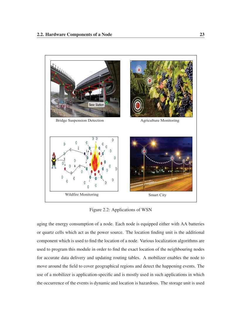
[53], forest wildfire monitoring [5], smart city [54] etc. Some of the applications of WSNs
are shown in Fig. 2.2.
2.2 Hardware Components of a Node
There are four basic components of any sensor node [55]: a sensor, a processor, a radio
transceiver and a power unit. Apart from these essential components, each node may have
additional components such as, a location finding unit, a mobilizer, a power generator, a
storage unit and an analog-to-digital converter (ADC). The hardware architecture of a node
is shown in Fig. 2.3.
The sensor unit is responsible to sense the deployed environment for capturing the data.
Each node is equipped with one or more sensors depending on the need of an application
and the type of generated data. The sensed data are the analog physical signals which need
to be digitized. The ADC unit transforms these analog signals to digital form and sends to a
processing unit which processes it and feeds into a radio transceiver for ultimate transmis-
sion to a neighbouring node. The radio transceiver is capable of simultaneous transmission
and reception of data from the neighbouring nodes. The power unit is responsible for man-
2.2. Hardware Components of a Node 23
Bridge Suspension Detection Agriculture Monitoring
Wildfire Monitoring Smart City
Figure 2.2: Applications of WSN
aging the energy consumption of a node. Each node is equipped either with AA batteries
or quartz cells which act as the power source. The location finding unit is the additional
component which is used to find the location of a node. Various localization algorithms are
used to program this module in order to find the exact location of the neighbouring nodes
for accurate data delivery and updating routing tables. A mobilizer enables the node to
move around the field to cover geographical regions and detect the happening events. The
use of a mobilizer is application-specific and is mostly used in such applications in which
the occurrence of the events is dynamic and location is hazardous. The storage unit is used

2.2. Hardware Components of a Node 24
Location finding unit Mobilizer
Power Unit
Sensor ADC Processor
Storage
Transceiver
Power Generator
Figure 2.3: Hardware Architecture of a Node
for the temporary storage of the sensed data. The processing unit retrieves the data from
the storage unit, processes it and transmits to the neighbouring nodes or a nearest base sta-
tion. Nowadays, smart sensor nodes are available in the market which are equipped with
relatively high amount of external flash memory (ROM) along with the primary storage
unit (RAM). Many applications require the nodes to operate over a longer period of time.
In these applications, the power unit may not be sufficient to sustain the nodes. To meet
these requirements, a power generator is used to prolong the lifetime of each node. The
power generator is provided in the form of a solar cell or energy scavenging technique [56].
The technological advancement in the field of WSN has brought small-sized, low-cost
and highly intelligent sensors in the market. These sensors, also known as smart sensors
are highly efficient in terms of processing, storage, transmission and energy consumption.
They support high data rate at the expense of relatively smaller amount of energy con-
sumption. Many people consider the node and sensor as the same device. They are not
2.2. Hardware Components of a Node 25
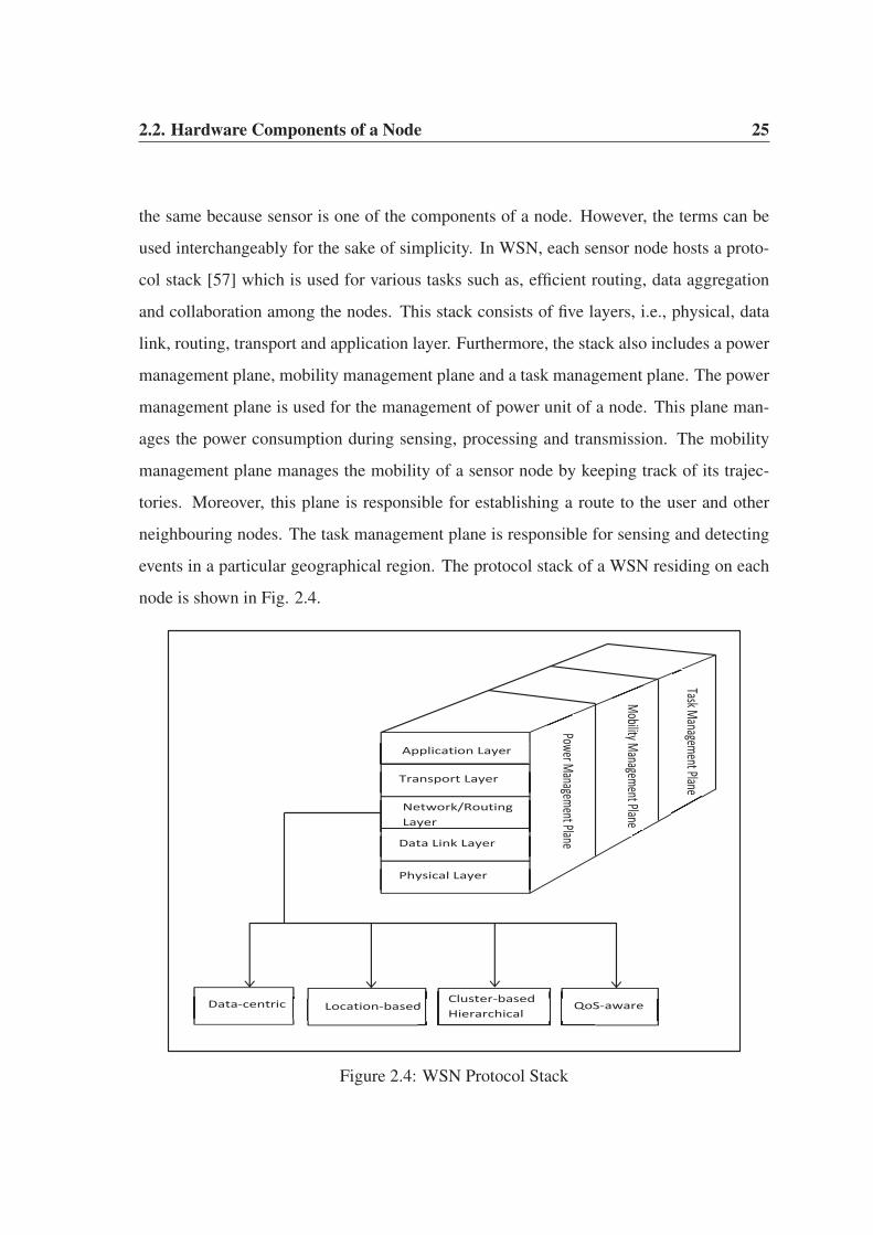
the same because sensor is one of the components of a node. However, the terms can be
used interchangeably for the sake of simplicity. In WSN, each sensor node hosts a proto-
col stack [57] which is used for various tasks such as, efficient routing, data aggregation
and collaboration among the nodes. This stack consists of five layers, i.e., physical, data
link, routing, transport and application layer. Furthermore, the stack also includes a power
management plane, mobility management plane and a task management plane. The power
management plane is used for the management of power unit of a node. This plane man-
ages the power consumption during sensing, processing and transmission. The mobility
management plane manages the mobility of a sensor node by keeping track of its trajec-
tories. Moreover, this plane is responsible for establishing a route to the user and other
neighbouring nodes. The task management plane is responsible for sensing and detecting
events in a particular geographical region. The protocol stack of a WSN residing on each
node is shown in Fig. 2.4.
Application Layer
Transport Layer
Network/Routing Layer
Data Link Layer
Physical Layer
Power Management Plane
Mobility Management Plane
Task Management Plane
Data-centric Location-based dCluster-based Hierarchical
QoS-aware
Figure 2.4: WSN Protocol Stack

2.3. WSN Routing Protocols 26
Similar to the TCP/IP model [58], the lower layers support the upper layers in WSN.
Each layer has specific protocols which carry out various tasks and functionalities per-
taining to that layer. Our research is specifically related to the routing layers of a WSN.
Therefore, only the routing protocols are shown in Fig. 2.4. Among these routing pro-
tocols, we will focus mainly on the cluster-based hierarchical protocols in view of their
distinguishing features as discussed in Chapter 1.
2.3 WSN Routing Protocols
In Chapter 1, we explained some of the distinguishing features of cluster-based hierarchi-
cal routing protocols which make them an ideal choice for any WSN application. These
features make them prominent among all other routing protocols used across WSN. Almost
all of the routing protocols rely on flooding to some extent for routing the data towards the
base station. Flooding has several drawbacks such as implosion and overlapping. The
cluster-based hierarchical protocols also suffer from these drawbacks. However, they ad-
dress them at the cluster head level which ensures that high quality data is delivered at
the base station with little or no redundancy. The rest of the protocols, i.e., data-centric,
location-based and QoS-aware suffer serious setbacks due to these drawbacks. The draw-
backs of flooding are shown in Fig. 2.5 [59].
d s
Source
Intermediate Nodes
Base station
(a) Implosion
Sources
Base Station
(b) Overlapping
Figure 2.5: Drawbacks of Flooding

2.3. WSN Routing Protocols 27
During implosion, a source node s broadcasts the sensed data packet d to all of its
neighbouring nodes, also known as intermediate nodes as shown in Fig. 2.5(a). Each in-
termediate node further transmits the data resulting in multiple copies of the same data at
the base station. In this figure, only three intermediate nodes are shown. The consequences
may further worsen provided there are multiple source nodes and a large number of inter-
mediate nodes. In overlapping, multiple source nodes sense the same geographical region.
In Fig. 2.5(b), a source node S1 senses a geographical region, known as 2, which is also
sensed by its neighbouring source node S2. A single region sensed by multiple source
nodes is known as an overlapping region. The sensing of an overlapping region results in
duplicate packets at the base station as shown in Fig. 2.5(b). Both implosion and over-
lapping consume a considerable amount of energy. They both lead to another drawback
known as resource blindness [11] in which the nodes do not take into account their energy
limitation while relaying the data to the base station.
To address the drawback of flooding, gossiping technique [60] was developed which
randomly selects any one of the intermediate nodes. The problem with gossiping is that
it is probable that the randomly selected intermediate node may be a malicious node or it
may have relatively lower energy than the rest of the neighbouring nodes. Moreover, it is
also possible that the randomly selected intermediate node may be far away as compared
to others which may further increase the energy consumption. The random selection in-
troduces too much latency during selection process which may not be a feasible option
for most of the priority-based data transmission applications. Both flooding and gossiping
have their own drawbacks such as data redundancy, energy consumption, and degradation
in the QoS parameters such as delay, jitter and throughput. Moreover, excessive delay
or latency may result in network congestion either at the nodes or at the links. Our next
section on cluster-based hierarchical routing protocols is specifically designated to address
these issues, i.e., high energy consumption and congestion in any WSN.
2.4. Cluster-based Hierarchical Routing Protocols 28
2.4 Cluster-based Hierarchical Routing Protocols
In a large-scale WSN, the data sensed by the source nodes experience excessive delay,
retransmission attempts, high energy consumption, high redundancy and low throughput.
Moreover, excessive delay and retransmission attempts lead to high network congestion
while high redundancy leads to deterioration in the quality of delivered data at the base
station. The cluster-based hierarchical routing protocols solve these problems by parti-
tioning a large-scale WSN into small clusters and achieve better results as compared to
data-centric, location-based and QoS-aware routing protocols. In this section, first we dis-
cuss the types of cluster-based hierarchical routing protocols with particular emphasis on
their energy consumption because our main objective is to improve the lifetime and quality
of data in these protocols. Next, we discuss the need for a congestion detection protocol in
hierarchical networks formed by cluster-based hierarchical routing protocols.
2.4.1 Types of Cluster-based Hierarchical Routing Protocols
Broadly speaking, the cluster-based hierarchical routing protocols are of two types: ran-
domly distributed (Self-organized) and centralized (Base Station Assisted). These two
types are differentiated based on their cluster characteristics, cluster head selection tech-
nique and clustering process [16]. In this section, first we explain the randomly distributed
cluster-based hierarchical routing protocols followed by the centralized cluster-based hier-
archical routing protocols.
In randomly distributed cluster-based hierarchical routing protocols, each node decides
on its own whether or not to become a cluster head. These protocols do not require any
negotiation among the sensor nodes for cluster head selection. Low-Energy Adaptive Clus-
tering Hierarchy (LEACH) [61] is designated as a pioneer protocol among the randomly
distributed cluster-based hierarchical routing protocols. LEACH is a self-organizing, adap-
tive clustering protocol that uses randomization for the uniform distribution of energy load
among the sensor nodes. The uniform distribution of energy load reduces the transmission
2.4.1. Types of Cluster-based Hierarchical Routing Protocols 29
burden on any particular sensor node. LEACH partitions a sensor field into small geo-
graphical regions known as clusters. Each cluster has a cluster head node which collects
and aggregates data from member nodes within the cluster and transmits to a base station.
Thus, the task of transmitting data to a base station is restricted to only few nodes, i.e., the
cluster heads. LEACH is iterative in nature and operates in rounds. Each round consists of
two phases, a set-up phase and a steady-state phase. Moreover, the set-up phase consists
of three sub-phases, i.e., cluster head selection, cluster formation and schedule creation.
The decision of any node to become a cluster head is influenced by certain factors such as,
the optimal percentage of cluster heads and the number of times a node has been elected
as cluster head so far. The optimal percentage of cluster head depends on the network
size and is decided at the time of network deployment. To elect itself as cluster head, each
node n chooses a random number between 0 and 1. If this number is less than the threshold
value T(n) of Equation 2.1, the node is elected as a cluster head for the current round.
T(n) =
⎧⎪⎪⎨⎪⎪⎩
kopt
1−kopt(rmod( 1kopt
)), i f n ∈ G,
0, otherwise.(2.1)
Here, kopt is the optimal percentage of cluster heads in each round, r is the current round
and G is the set of nodes that have not been elected as cluster heads in the past 1kopt
rounds.
The value of kopt normally ranges from 5% to 10% depending on the size of a network.
Using Equation 2.1, each node will get a chance to become a cluster head at some point
within 1kopt
rounds. During the first round, i.e., r = 0, each node has a probability kopt of
becoming a cluster head. The nodes which elect themselves as cluster heads in round 0
cannot become cluster heads for the next 1kopt
rounds. As a result, the probability of the
remaining nodes to become cluster heads increases for the next 1kopt
rounds. After 1kopt
− 1
rounds, T = 1 for any node that has not yet been elected as cluster head. After 1kopt
rounds,
all the nodes are once again eligible to be elected as cluster heads. In Equation 2.1, if n
/∈ G, it means that n has already been elected as cluster head over the past 1kopt
rounds.

2.4.1. Types of Cluster-based Hierarchical Routing Protocols 30
Therefore, T=0 and n cannot be elected as cluster head for the current round.
Each cluster head broadcasts an advertisement message containing its ID and location
information. The neighbouring nodes keep their transmissions on to hear the advertisement
messages from the elected cluster heads. They may receive multiple advertisement mes-
sages from the cluster heads located in their vicinity. However, each neighbouring node
associates itself with a cluster head having the strongest signal strength. Once a neigh-
bouring node decides to join a particular cluster head, it transmits a join-request message
to that cluster head. The join-request messages show the willingness of neighbouring
nodes in cluster formation and participation as member nodes in cluster communication.
Each cluster head must keep its receiver on during the transmission of join-request mes-
sages. These join-request messages enable each cluster head to determine the size of its
respective cluster, i.e., the number of member nodes in a cluster. Once each cluster head
receives join-request messages, TDMA slots are assigned to the member nodes. The allo-
cation of TDMA slots, also known as TDMA schedule, signals the end of cluster formation
sub-phase and initiation of schedule creation sub-phase. After schedule creation, the nodes
are ready to transmit the sensed data to their respective cluster heads. The assignment of
TDMA slots reduces the contention for wireless medium among the member nodes and
they can transmit their data using the allocated slots. The selection of cluster heads, the
formation of clusters and the creation of TDMA schedule signals the end of set-up phase
and initiation of steady-state phase. During the steady-state phase, each node remains in
sleep mode and wakes up only on its allocated TDMA schedule to transmit the data to
its designated cluster head. Each member node goes to sleep mode after the transmission
of its data. However, each cluster head must keep its receiver on all the time during the
steady-state phase. Once each cluster head receives data from its member nodes, it aggre-
gates the data and transmits to a base station. It is highly probable that the neighbouring
member nodes may have sensed similar data packets, hence, there will be redundancy in
the data packets.
To reduce or eliminate the redundancy, each cluster head performs fusion by eliminat-
2.4.1. Types of Cluster-based Hierarchical Routing Protocols 31
ing multiple copies of the same data. Each cluster head is capable to compress various
data packets into a single composite signal. The tasks of each cluster head are resource-
intensive because it performs data aggregation, fusion and long-haul transmission to a base
station. Moreover, cluster head-advertisement along with keeping the receiver on during
join-request messages are also resource-intensive tasks. All these tasks consume a consid-
erable amount of energy. As a result, a new set of cluster heads are elected in each round
for the uniform distribution of energy load on all the nodes in the network. Once the cluster
heads transmit the aggregated data to a base station, the steady-state phase is completed.
The completion of set-up phase and steady-state phase is coined as one complete round.
A new round starts after the completion of steady-state phase and the same operations,
i.e., set-up and steady-state phases are repeated in each round. The operations performed
during set-up and steady-state phases is shown in Fig. 2.6.
In Fig. 2.6(a), the sensor field at the time of network deployment is shown. The nodes
are yet to organize themselves into clusters. In Fig. 2.6(b), the cluster heads are elected
and clusters are formed around them. Each cluster head collects data from member nodes
and transmits to a base station which may be located inside or outside the sensor field
depending on the need of an application. Once data is transmitted to a base station, a new
set of cluster heads are elected in the subsequent round as shown in Fig. 2.6(c). Each
cluster head creates a schedule for member nodes which enable them to transmit data on
their turn. In Fig. 2.6(d), the internal operation within each cluster is shown. The member
nodes remain in sleep mode, but wake up on their allocated schedule and transmit data to
their respective cluster heads.
LEACH protocol has a single hierarchy, i.e., member nodes transmit their data to the
cluster heads which in turn transmit to a base station. However, in many applications,
there may be a dense deployment of nodes in a wide geographical region. In that case, the
member nodes may need to transmit over a long distance to the base station. Moreover,
the cluster heads may be located at a far distance from the base station. As a result, both
the member nodes and cluster heads may deplete their energy much faster than expected.

2.4.1. Types of Cluster-based Hierarchical Routing Protocols 32
(a) Sensor Field at the Time of Deployment (b) Cluster Formation in Round x
(c) Cluster Formation in Round x+1
Member Node Cluster Head
(d) Communication at the Cluster Level
Figure 2.6: Randomly Distributed Cluster-based Hierarchical Routing
To solve the energy consumption problem, multi-level hierarchy was introduced in which
the member nodes transmit data to their respective cluster heads which in turn transmit
to the cluster heads one level above them. In Fig. 2.7, the different levels of a randomly
distributed cluster-based hierarchical WSN architecture is shown.
The cluster heads at different levels in a multi-level hierarchical architecture are sim-
ilar to each other in terms of operation. They have their own member nodes and they act
as relay nodes for the lower-level cluster heads. Multi-level hierarchical architecture has
its own benefits such as efficient data aggregation and fusion and lower energy consump-
tion. However, the sensed data experience excessive delay at different levels during its

2.4.1. Types of Cluster-based Hierarchical Routing Protocols 33
Base Station
Member Nodes Cluster Head
(a) Single-level Hierarchical WSN
CH1
CH11
CH12 CH13
Base Station
First Level Cluster Head Second Level Cluster Head
Intra-cluster Communication Inter-cluster Communication
(b) Multi-level Hierarchical WSN
Figure 2.7: Different Levels of Hierarchy
transit. The cluster heads at each level perform data aggregation and fusion to improve
the quality of data which in turn delay the transmission of data to the base station. As a
result, multi-level hierarchical architecture may not be beneficial for applications where
the timely delivery of data at the base station is of utmost importance. Irrespective of a
single-level or multi-level hierarchical architecture, the randomly distributed cluster-based
hierarchical routing protocols elect cluster heads using a random number generation tech-
nique. The probabilistic selection of cluster heads has a potential risk of low energy nodes
being elected as cluster heads in subsequent rounds. Moreover, Equation 2.1 cannot guar-
antee an optimal number of cluster heads in each round. These protocols elect anything
between 0 and 22 cluster heads in various rounds (explained in Chapter 3). If no cluster
heads are elected in a particular round, it means that these protocols operate similar to the
data-centric and location-based protocols as discussed in Chapter 1.
One way of solving the optimal selection problem is the inclusion of residual energy
value of each node in Equation 2.1. The cluster heads need to be elected based on the resid-
ual energy of the nodes. There exist various schemes which elect the cluster heads based on
the available resources of a node. For example, protocols such as LEACH-B [62], Energy-

2.4.1. Types of Cluster-based Hierarchical Routing Protocols 34
LEACH [63], Distributed Energy-efficient Clustering protocol (DEEC) [64] and Hybrid
Energy-efficient Distributed Clustering protocol (HEED) [65] elect the cluster heads based
on the residual energy of the nodes, dissipated energy during the current round and aver-
age node energy. Another way of solving this problem is assigning the responsibility of
selection to a central controller, i.e., a base station. In [66], the authors proposed LEACH-
Centralized (LEACH-C) protocol which adopts a centralized approach for cluster head
selection. The nodes having remaining energy greater than the average residual energy are
elected as cluster heads in each round. However, it is highly probable that there will be
a large number of such nodes in each round which will result in too many cluster heads.
There are numerous protocols which are based on LEACH-C and rely on base station for
cluster head selection. In [67], Base-Station Initiated Dynamic Routing Protocol (BIDRP)
is proposed which is specifically used for heterogeneous sensor networks. In BIDRP, some
nodes have higher energy in the network. These nodes are always elected by the base sta-
tion as cluster heads in each round. In [68], the authors proposed a centralized scheme
which elected an optimal percentage of cluster heads (5% of total nodes). Each round
results in balanced clusters which enhance network stability, scalability and data aggrega-
tion. The main drawback of the centralized approach is the excessive delay experienced in
cluster head selection. The base station consumes a considerable amount of time during
selection process. Moreover, the selection process is complicated and requires extensive
computation.
The main difference between the centralized approach and the randomly distributed
approach is the cluster head selection methodology. In randomly distributed cluster-based
hierarchical routing protocols, each node decide itself whether or not to become a cluster
head. However, in centralized cluster-based hierarchical routing protocols, the base station
is the main entity which elects the cluster heads. Moreover, the base station tries to form
balanced clusters in which there is equal distribution of nodes. The rest of the operations,
i.e., cluster formation, cluster head advertisement, schedule creation and data transmission
are exactly similar in both these approaches. Furthermore, the concept of single-level and

2.4.2. Congestion Detection in Cluster-based Hierarchical Protocols 35
multi-level hierarchical architecture is equally applicable to both these approaches.
2.4.2 Congestion Detection in Cluster-based Hierarchical Protocols
In WSNs, the protocols at transport layer are responsible for establishing an end-to-end
connection to provide various services such as data flow, reliability, packet loss recovery
and congestion detection and mitigation [69]. Moreover, these protocols manage band-
width allocation and support heterogeneous application. Transport protocols such as User
Datagram Protocol (UDP) [70] and Transport Control Protocol (TCP) [71] are not suit-
able for WSN applications due to their nature of operation. The UDP protocol does not
offer flow control, reliability and congestion control. These are desirable features of any
WSN application. In contrast, TCP protocol requires an end-to-end reliability and retrans-
mission of lost packets. However in WSNs, the nodes are equipped with small batteries
which cannot afford such expensive retransmission of data to the base station. These nodes
support hop-by-hop communication for data delivery and the rate of flow on each hop is
different. Therefore, it is very difficult to establish a reliable end-to-end connection from a
source node to the base station for data delivery. In these networks, some hops have higher
network traffic compared to others. On any hop, a node may fail or a link may be broken
down, in which case, alternate paths need to be established.
The concept of hop-by-hop and end-to-end connection is shown in Fig. 2.8. In this
figure, multiple end-to-end connections are shown. On one such connection, there are 8
hops between a source node and the base station. It is difficult to ensure the reliability of
this connection between them. If the overloaded nodes fail or the hops on which they reside
are broken down, the upstream traffic to the base station will be lost. These overloaded
nodes and the hops on which they reside causes congestion during heavy traffic flow. In
WSNs, congestion arises when the nodes are overloaded, i.e., the packet arrival rate is
higher than the packet processing rate. Congestion also occurs when the rate of traffic on
the links exceed than their available capacity. Congestion on the links mainly occurs due
to interference, contention for wireless channel and blind mote problem [72].

2.4.2. Congestion Detection in Cluster-based Hierarchical Protocols 36
Base Station
1
2
3
4
5
6
7
8
Source Nodes Overloaded Nodes
Figure 2.8: Hop-by-Hop Communication vs. End-to-End Communication
In WSNs, congestion causes packet loss, latency, degradation in network throughput,
energy consumption and blockage of new connections. In literature, there exists various
congestion detection and mitigation protocols at transport layer. In [73], the authors pro-
posed an end-to-end, hop-by-hop congestion control protocol known as COngestion De-
tection and Avoidance (CODA). In CODA, the nodes near congested regions drop packets
according to an Additive Increase and Multiplicative Decrease (AIMD) scheme [74] by
monitoring and controlling the packet generation rate of each source node. CODA de-
creases the level of congestion but the retransmission of packets still remains high, which
imposes an extra burden on energy-starved sensor nodes. In [75], the authors proposed the
Fusion protocol for congestion detection based on static threshold levels. In Fusion, each
node dynamically acquires a channel based on the occurrence of events, thereby making it
difficult to pre-set a suitable threshold level. In [76], the Event-to-Sink Reliable Transport
(ESRT) protocol was proposed. In ESRT, each node monitors its buffer occupancy for con-
gestion detection. When the buffer is full, each node set a one bit congestion-notification
2.4.2. Congestion Detection in Cluster-based Hierarchical Protocols 37
field in the header of each outgoing packet to inform the neighbouring nodes about the
current status of its buffer. Each source node transmits data to the base station periodically
at a predetermined rate. The drawback of ESRT is that the predetermined rate is applicable
to each source node, which makes it unfair in terms of resource utilization. This is because
the nodes in the congested regions are not capable of transmitting at the predetermined
rate set by the base station. In [77], the authors investigated network congestion behaviour
based on the optimal packet size using the Automatic Repeat reQuest (ARQ) protocol. The
transmission of smaller packets with a high Bit Error Rate (BER) and larger packets with
a low BER reduces the number of retransmission attempts and it effectively improves the
network resource utilization. The proposed scheme determines the optimal packet size to
reduce congestion with unpredictable BERs.
The existing congestion detection and mitigation protocols have certain drawbacks
[78]. These protocols detect and mitigate congestion either through hop-by-hop or through
end-to-end approaches. These protocols do not support an adaptive congestion control
mechanism which has the ability to integrate both these approaches. Although, CODA
uses both the approaches, however, it has no adaptive congestion control mechanism. As a
result, CODA and other existing transport layer congestion detection and mitigation proto-
cols are not applicable to a large scale WSN supporting diverse applications. The use of an
adaptive mechanism is desirable because it reduces the energy consumption and simplifies
the operation of sensor nodes. Another major drawback of the existing protocols is that
they provide either application-level reliability or packet-level reliability, not both of them.
If a sensor network supports two different applications such that, one of the application
requires packet level reliability and another one requires application-level reliability, then
the existing protocols may not produce optimal results. Moreover, the existing transport
layer protocols for congestion detection and mitigation lack the support for cross-layer op-
timization. However, the lower layers, i.e., the network layer and data link layer provide
various services to the transport layer. The services of these layers can be used to develop
a robust congestion detection and mitigation protocol.
2.5. Sybil Attack Detection 38
In view of the above discussion, our aim is to develop an energy-efficient cluster-based
hierarchical routing protocol which detects congestion in a heterogeneous WSN support-
ing two different applications. Our proposed protocol partitions the network into small
clusters. The presence of clusters in a network reduces the number of hops which eases
the provisioning of end-to-end reliability as well. Furthermore, the number of hops di-
rectly affects the performance of any congestion detection and mitigation protocol. If a
network has less hops, it mean that it is relatively easy to detect the nodes and links caus-
ing congestion in that network. Our proposed protocol is energy-efficient as well because
it effectively schedules the duty-cycling of each node, i.e., the nodes remain in sleep mode
and wake up only on their allocated time slots to transmit data. In our proposed proto-
col, one application has high priority while the second has low priority. At the time of
congestion, the nodes drop low priority packets and transmit only the high priority pack-
ets to reduce the effect of congestion. The work in Chapter 4 is solely dedicated to this
contribution.
2.5 Sybil Attack Detection
The word Sybil is named after the subject of a book titled Sybil, a case study of a woman
diagnosed with dissociative identity disorder [79]. The name Sybil was suggested in or
before 2002 by Brian Zill at Microsoft Research. First we discuss the existing literature
on Sybil attack detection in WSN in Section 2.5.1 followed by the need for a Sybil attack
detection scheme in a forest wildfire monitoring application in Section 2.5.2.
2.5.1 Detection of Sybil Attack in WSN
In WSNs, communication over an error-prone wireless channel exposes nodes to various
types of malicious activities. Among them is Sybil attack where an adversary forges multi-
ple identities at a given time to mislead legitimate nodes into believing that they are having
many neighbours as shown in Fig. 2.9. An adversary may either fabricate such identities
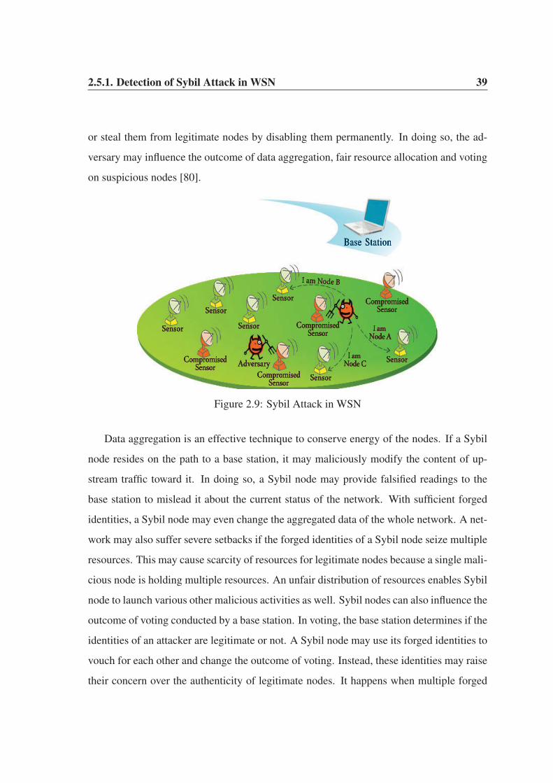
2.5.1. Detection of Sybil Attack in WSN 39
or steal them from legitimate nodes by disabling them permanently. In doing so, the ad-
versary may influence the outcome of data aggregation, fair resource allocation and voting
on suspicious nodes [80].
Figure 2.9: Sybil Attack in WSN
Data aggregation is an effective technique to conserve energy of the nodes. If a Sybil
node resides on the path to a base station, it may maliciously modify the content of up-
stream traffic toward it. In doing so, a Sybil node may provide falsified readings to the
base station to mislead it about the current status of the network. With sufficient forged
identities, a Sybil node may even change the aggregated data of the whole network. A net-
work may also suffer severe setbacks if the forged identities of a Sybil node seize multiple
resources. This may cause scarcity of resources for legitimate nodes because a single mali-
cious node is holding multiple resources. An unfair distribution of resources enables Sybil
node to launch various other malicious activities as well. Sybil nodes can also influence the
outcome of voting conducted by a base station. In voting, the base station determines if the
identities of an attacker are legitimate or not. A Sybil node may use its forged identities to
vouch for each other and change the outcome of voting. Instead, these identities may raise
their concern over the authenticity of legitimate nodes. It happens when multiple forged

2.5.1. Detection of Sybil Attack in WSN 40
identities inform the base station that one or more legitimate nodes are misbehaving and
are malicious in nature.
The unstructured and distributed environment along with broadcast nature of commu-
nication in WSNs suits well to Sybil attacks. Various protection mechanisms have been
developed to protect the nodes against this type of attacks. A radio resource testing ap-
proach for detecting forged identities was proposed in [30]. It was assumed that a sensor
node was incapable of simultaneous transmission or reception on a single radio. Moreover,
a physical node may forge multiple identities but is incapable to use a single channel for
these identities at a given time. Apart from radio resource testing, the authors also pro-
posed a key validation approach for the random key pre-distribution. However, it requires
excessive resources on part of each node and is computationally complex requiring ample
amount of memory space. In [81], the authors proposed a scheme based on the assumption
that probability of two nodes having exactly the same set of neighbours was extremely
low provided that a network had a high node density. They argued that forged identities
typically had the same set of neighbours because they were all associated with the same
physical device. Therefore, the presence of a malicious node can easily be detected by
checking the neighbourhood of a suspected victim of a Sybil attack. In [82], the authors
proposed a Received Signal Strength Indicator (RSSI) based solution for a Sybil attack
detection. They argued that even though an RSSI was a time-varying parameter and un-
reliable in nature, however, using RSSI ratio from multiple receivers might be used for
Sybil attack detection. An identity-based detection scheme for Sybil and spoofing attacks
in WSNs was proposed in [83]. The proposed approach uses a detector to identity ma-
licious activities of the malevolent entities capable of adjusting their transmission power.
The detector locates the positions of such entities and prevents them from network partic-
ipation. In [84], the authors proposed Secure Code Update By Attestation (SCUBA) to
detect and recover nodes compromised by an intruder. In SCUBA, public key is used for
authentication between each sensor node and a base station. It is the job of a base station to
determine the authenticity of each node. The node ID and the public key of a base station
2.5.2. Detection of Sybil attack in a Wildfire Monitoring Application 41
is stored in Read only Memory (ROM) of each node. The node ID is used as an input
for Indisputable Code Execution (ICE), a verification function which generates a specific
checksum. SCUBA is a strong defence mechanism against Sybil attack and is beneficial in
circumstances when a malicious node impersonates as a legitimate node. SCUBA uses the
underlying principles of Code attestation, a technique to validate the code in the memory
of each sensor node. The code of a malicious node differs from that of a legitimate node.
All of detection techniques mentioned above are designed for conventional routing
protocols such as, data-centric in which flooding is exclusively or partially used to regu-
late traffic flow. Flooding allows intermediate nodes to broadcast data and control packets
on their ways to base station from source nodes [37]. Duplicate packets keep circulating
in the network which causes excessive energy consumption, delay, congestion, implosion
and overlapping [38]. Our goal is to develop a lightweight Sybil attack detection scheme
for a centralized cluster-based hierarchical network. Our proposed scheme for Sybil at-
tack detection has two main objectives. First, we design a Sybil attack detection scheme
which requires collaboration of only two nodes. Second, we implement our scheme for a
centralized cluster-based hierarchical network to prevent Sybil nodes from participating in
cluster head selection as these nodes are capable of forming multiple virtual clusters using
their forged identities. Our proposed approach is lightweight in terms of number of nodes
required to detect a Sybil attack. Moreover, it is efficient in terms of prolonging network
lifetime, cluster head selection, energy consumption, packet loss rate and packet delivery
ratio. The contribution of Chapter 5 is dedicated to this work.
2.5.2 Detection of Sybil attack in a Wildfire Monitoring Application
WSNs have widely been investigated for monitoring the forest environment for a possible
outbreak of a wildfire. The existing research on wildfire monitoring application focus
mainly on QoS parameters of the data collected from a forest environment. The main
objective of the existing research is to gather time-critical, delay-sensitive data and report
them to a base station without further delay. These studies do not focus on the security

2.5.2. Detection of Sybil attack in a Wildfire Monitoring Application 42
aspects of the network in general and the data collected from the network in particular.
However, if none of the previous studies have focused on security provisioning within a
forest environment, it does not mean that communication in such an environment is free
from security threats and vulnerabilities. Such applications are highly vulnerable to threats
due to hostile environment of the forest and error-prone communication links over which
the sensor nodes are communicating. Like any other application, security provisioning is a
major challenging issue in wildfire monitoring application. In this section, first we provide
the existing literature on the use of WSNs for monitoring a wildfire. We mainly focus
on such studies in which cluster-based hierarchical networks are used as the underlying
platforms. Next, we discuss the need for a Sybil attack detection scheme in a wildfire
monitoring application.
In literature, there exist various works on wildfire monitoring using an underlying
cluster-based hierarchical platform. In [85], the Energy-efficient Fire Monitoring Proto-
col (EFMP) was proposed which operates in three states namely, watch, slave and master.
In a watch state, the nodes observe the detection of a possible wildfire. Among all the
cluster heads, the one which first detects a fire, known as master head, transforms itself
into master state. The master head informs all other cluster heads which transform them-
selves to slave state in order to act as slave heads within the network. In this fashion, a
layered hierarchical architectural model is formed. Irrespective of master or slave head,
all the cluster heads collect data within their clusters. However, only a master head is eli-
gible to transmit the data to a base station. All slave heads transmit their data to a master
head which aggregates the data and transmits to a base station. EFMP reduces energy
consumption because of master and slave head concepts. In [86], the authors proposed a
simulation framework to monitor and detect a possible forest fire. When the environmental
conditions are normal, the nodes remain in low-duty cycle to conserve energy. However,
during a possible fire threat, the nodes become aggressive and coordinate with each other
at a much faster rate to ensure that critical alert packets are reported instantly to a base
station.
2.5.2. Detection of Sybil attack in a Wildfire Monitoring Application 43
The operation of the nodes depends on terrain, current weather forecasts and season
of the year. Upon network deployment, the sensor nodes associate themselves with their
nearest cluster heads. Each cluster head assigns transmission slots to member nodes which
enable them to avoid contention for transmission on a wireless link. Furthermore, each
cluster head has the ability to transform the member nodes into sleep mode in a Round
Robin fashion to minimize their energy consumption. In the event of a fire detection, the
nodes in close vicinity of a fire alter their normal transmission patterns and react more
aggressively. If a fire ignites near a cluster head, it needs to immediately elect the most
suitable member node as a replacement cluster head. A cluster-based hierarchical WSN to
detect a possible wildfire was proposed in [87]. Sensor nodes were deployed to measure
relative humidity and temperature readings within a forest. The cluster heads collect alarm
packets from member nodes and transmit to a gateway node which ultimately delivers it
to a centralized monitoring computer. In [88], the authors proposed a reliable wildfire
monitoring system for a sparsely deployed WSN. The proposed scheme is reactive [38]
in nature because the nodes remain in sleep mode and wake up only when an event is de-
tected. While awake, each node remains in normal or in an alert mode for transmission of
captured data without further delay. Moreover, the authors proposed separate routing paths
for normal data and delay-sensitive data. In [89], the behaviour of nodes within a forest
was studied. The authors proposed a mobility constraint model for providing adequate
coverage to such events. They argued that the risk factors of a possible wildfire ignition
characterise the coverage density of the nodes. Those areas which are more vulnerable to
a possible wildfire occurrence require higher coverage densities. To provide accurate read-
ings of the happening events, the nodes need to move toward hotspots to ensure complete
network coverage.
The existing wildfire monitoring techniques do not address any security challenges
incurred within a forest which motivate us to fill the research gap by proposing a Sybil
attack detection scheme for a wildfire monitoring application. We propose two different
detection techniques for a possible Sybil attack. Different types of threshold-based queries

2.6. Internet of Things 44
are used to collect data within a forest environment. Furthermore, mobility is provided
by the two coordinating base stations to enhance network coverage and avoid any hotspot
issues. The contribution of Chapter 6 is dedicated to this work.
2.6 Internet of Things
The term Internet of Things (IoT) was first coined by Kevin Ashton in 1999 in the con-
text of supply chain management [90]. However, today the IoT expands to a vast majority
of fields such as healthcare, transportation logistics, industrial automation and agricul-
ture [91]. Today’s Internet has been rapidly moving from traditional computing platforms
such as computers and laptops, to multiple miniature devices capable of executing a vari-
ety of applications. Miniature sensors and RFID tags embedded in physical objects have
enabled the emergence of smart objects in recent years. Any physical object is smart as
long as it possess three distinguishing features, i.e., awareness, representation and inter-
action [92]. Awareness is the ability of an object to understand, i.e., sensing, interpreting
and reacting to the events occuring within an environment. Representation refers to the
application and programming model of an object. Interaction is the ability of an object
to communicate and negotiate with a user in terms of input, output, control and feedback.
Embedded sensors and RFID tags in objects such as refrigerators, washing machines, cars,
and personal gadgets have enabled them to collaborate with each other and share valuable
information about the physical world. Advances in wireless technologies and increased
number of physical objects integrating with the Internet are enabling the transition of In-
ternet into a service-oriented future Internet, such as the IoT [93]. This transition enables
our environment to be more interactive and informative. In 2011, the number of physical
objects connected with the Internet has surpassed the human population. Currently, there
are around 9 billion objects connected with the Internet. It is estimated that around 50
billion such objects will be integrated within the Internet by 2020 [94]. This integration
and interoperable communication will generate an enormous amount of data which need
2.6. Internet of Things 45
to be stored, processed, analysed and transmitted in a very systematic manner.
This interaction with the physical world is not a straight forward process and requires
certain norms and regulations which need to be obeyed. First, the presence of embed-
ded sensors and RFID tags make these objects constrained on various resources such as
available storage, data rate, computation, and battery power. A physical object itself is
not resource-starving but the sensor or an RFID tag embedded in it is resource-constrained
in nature. Such physical objects can communicate with each other in the presence of an
embedded sensor or RFID tag attach to them. This is because, each object requires an
ID such as IP address, for network communication. In case of an embedded sensor, the
IP address is assigned to the sensor node. If the object uses RFID tag instead of a sensor
node, then it communicates with other objects using its tag. To provide IP addresses to 50
billion objects is not an easy task and IPv4 is clearly not sufficient to facilitate such a sheer
volume of objects. The addressing space of IPv6 is sufficient to provide unique addresses
to each object currently connected or will be connecting to the Internet in future. IPv6 can
provide up to 3.4× 1038 addresses to computers, routers and other real-world objects [95].
At first glance, it seems that IPv6 has solved all the problems, i.e., connecting objects
to the Internet. However, the provisioning of IPv6 in physical objects is not that simple.
The embedded sensor in each object may be powered by an 8-bit, 16-bit or 32-bit micro-
controller with 64Kbytes or more of flash memory. The sensor nodes use IEEE 802.15.4
standard which supports only 127 bytes of packet size [96]. Therefore, each IPv6 packet
needs to be in a simple format, i.e., removing its high-level complexity and redundancy, to
make usable for physical objects. The integration of physical objects with the traditional
Internet is shown in Fig. 2.10.
In Fig. 2.10, the traditional Internet is on one side of the network while an IPv6 over
Low-power Wireless Personal Area Network (6LoWPAN) is on the other side of the net-
work. The 6LoWPAN is based on the idea that “IP address could and should be applicable
even to the smallest devices [97]” and “the low-power objects having limited storage, pro-
cessing capabilities, battery power and other available resources should be able to partici-

2.6. Internet of Things 46
6LoWPAN
Traditional Internet
Figure 2.10: Integration of Physical Objects with Internet-IoT

2.6. Internet of Things 47
pate in the IoT [98]”. The 6LoWPAN working group has defined various encapsulation and
header compression techniques so that IPv6 packets can be transmitted and received over
low-power networks such as IEEE 802.15.4. In Fig. 2.10, the 6LoWPAN specifications
manage the traffic flow from traditional Internet toward the objects and vice-versa. The
6LoWPAN uses encapsulation and header compression techniques to strip down highly-
complex IPv6 packets incoming from traditional Internet. As a result, the packets become
lightweight and do not possess the headers and complexity imposed by the upper lay-
ers. Likewise, the 6LoWPAN specifications configure smaller packets, i.e., those packets
which are flowing from 6LoWPAN to the traditional Internet. In that case, the header and
high-level complexity are added to each packet before its delivery to traditional Internet.
The protocol stack at the nodes in these two networks is shown in Fig. 2.11.
CoAP
UDP
6LoWPAN
IEEE 802.15.4 MAC
IEEE 802.15.4 PHY
HTTP
TCP
IP
Ethernet MAC
Ethernet PHY
Application Layer
Transport Layer
Network Layer
Data Link Layer
Physical Layer
Figure 2.11: Protocol Stack at the Nodes
The nodes2 in the traditional Internet of Fig. 2.10 use the TCP/IP model. On the other
hand, the nodes in 6LoWPAN use a lightweight protocol stack which meets the require-
ments of these low-powered and resource-starving objects. The use of Hypertext Transfer
Protocol (HTTP) in 6LoWPAN or any IoT is not an optimal choice because HTTP re-
quires abundant of network resources and the request-response interaction model of HTTP
does not match the event-driven nature of applications in WSNs [99]. To support and de-
2A node does not necessarily mean a sensor node. Any device capable of sending and receiving data is a
node such as laptop, desktop, refrigerator and mobile phone.
2.6.1. Constrained Application Protocol 48
velop applications in any IoT, the Internet Engineering Task Force (IETF)3 came up with
a “lightweight HTTP ”, known as Constrained Application Protocol (CoAP).
2.6.1 Constrained Application Protocol
CoAP [100] is an application layer protocol which is designed to allow the exchange of
messages between resource-constrained objects over the resource-constrained networks.
Given its simplicity, it is also easier to implement CoAP-based systems on small embed-
ded hardware. The protocol inherits the lightweight features of HTTP and the conversion
between the two protocols is relatively easy. CoAP provides an HTTP-like request and
response interaction paradigm, where the objects can interact by sending a request and
receiving a response. Similar to web services, objects are addressed using IP addresses
and port number. Resources are accessed by each object via Restful [101] URIs4, i.e.,
objects in the form of clients and server communicates with each other in such a way
that a resource resides over a server and each client access it by using the Uniform Re-
source Locator (URL) of the resource. CoAP supports the discovery of various resources
hosted by a server. A CoAP client needs to learn about the services offered by a CoAP
server [102]. Each client learns about the server via a URI that refers to a resource in
the namespace of the server. Alternatively, a client can use “Multicast CoAP” and “All
CoAP Nodes” multicast address to find a CoAP server. CoAP is based on the UDP pro-
tocol, hence, the packets may arrive out of order, missing and/or corrupted. The protocol
supports four types of messages: CON, NON, ACK and RST as shown in Table 2.1. To
provide reliability, each client transmits confirmable (CON) messages to the server which
need to be acknowledged (ACK) in a pre-specified duration. A request can carry either a
confirmable or non-confirmable message. A non-confirmable (NON) request is used for
unreliable transmissions such as, a request for sensor measurements recorded periodically
by a server. Even if one or more values of sensor measurements are missing, there is not
3http://www.ietf.org/4REST stands for Representational State Transfer while URI stands for Uniform Resource Identifier
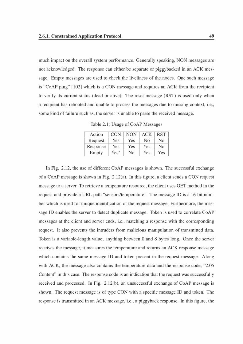
2.6.1. Constrained Application Protocol 49
much impact on the overall system performance. Generally speaking, NON messages are
not acknowledged. The response can either be separate or piggybacked in an ACK mes-
sage. Empty messages are used to check the liveliness of the nodes. One such message
is “CoAP ping” [102] which is a CON message and requires an ACK from the recipient
to verify its current status (dead or alive). The reset message (RST) is used only when
a recipient has rebooted and unable to process the messages due to missing context, i.e.,
some kind of failure such as, the server is unable to parse the received message.
Table 2.1: Usage of CoAP Messages
Action CON NON ACK RST
Request Yes Yes No No
Response Yes Yes Yes No
Empty Yes∗ No Yes Yes
In Fig. 2.12, the use of different CoAP messages is shown. The successful exchange
of a CoAP message is shown in Fig. 2.12(a). In this figure, a client sends a CON request
message to a server. To retrieve a temperature resource, the client uses GET method in the
request and provide a URL path “sensors/temperature”. The message ID is a 16-bit num-
ber which is used for unique identification of the request message. Furthermore, the mes-
sage ID enables the server to detect duplicate message. Token is used to correlate CoAP
messages at the client and server ends, i.e., matching a response with the corresponding
request. It also prevents the intruders from malicious manipulation of transmitted data.
Token is a variable-length value; anything between 0 and 8 bytes long. Once the server
receives the message, it measures the temperature and returns an ACK response message
which contains the same message ID and token present in the request message. Along
with ACK, the message also contains the temperature data and the response code, “2.05
Content” in this case. The response code is an indication that the request was successfully
received and processed. In Fig. 2.12(b), an unsuccessful exchange of CoAP message is
shown. The request message is of type CON with a specific message ID and token. The
response is transmitted in an ACK message, i.e., a piggyback response. In this figure, the

2.6.1. Constrained Application Protocol 50
server is unable to process the request, so it transmits the response with a response code
“4.04 Not Found ” with a description that the URI path in the request is invalid.
Client
ACK Message ID=0x1000 Token=0x2345 2.05 Content “30 0C”
CON GET sensors/temperature Message ID=0x1000 Token=0x2345
Server
(a) CON Message Successful Exchange
CON GET sensors/temperature Message ID=0x1001 Token=0x2346
ACK Message ID=0x1001 Token=0x2346 4.04 Not Found Invalid Path URI
Client Server
(b) CON Message Failure Exchange
NON GET sensors/temperature Message ID=0x1002 Token=0x2347
NON Message ID=0x1002 Token=0x2347 2.05 Content “37 0C”
Client Server
(c) NON Message Successful Exchange
CON GET sensors/temperature Message ID=0x1004 Token=0x2348
RST Message ID=0x1004 Token=0x2348 4.04 Not Found URL path in request is incorrect
Client Server
(d) Use of RST in Message Exchange
Figure 2.12: Exchange of CoAP Messages
In Fig. 2.12(c), the successful exchange of NON message is shown. The client sends
the request in a NON message, which literally means that there is no guarantee that the
client will receive a response from the server. The server transmits the response in a NON
message having a specific token, message ID and the requested data. If the response mes-
sage is lost, the client needs to send a request again. The use of RST in a response message
is shown in Fig. 2.12(d). The client sends a CON request which the server is unable to
interpret and replies back with a RST message. The response code is “4.04 Not Found”
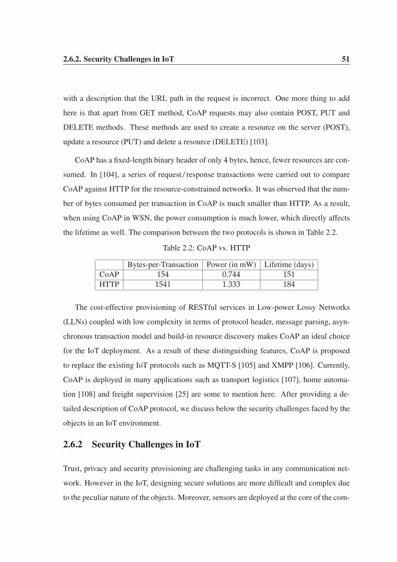
2.6.2. Security Challenges in IoT 51
with a description that the URL path in the request is incorrect. One more thing to add
here is that apart from GET method, CoAP requests may also contain POST, PUT and
DELETE methods. These methods are used to create a resource on the server (POST),
update a resource (PUT) and delete a resource (DELETE) [103].
CoAP has a fixed-length binary header of only 4 bytes, hence, fewer resources are con-
sumed. In [104], a series of request/response transactions were carried out to compare
CoAP against HTTP for the resource-constrained networks. It was observed that the num-
ber of bytes consumed per transaction in CoAP is much smaller than HTTP. As a result,
when using CoAP in WSN, the power consumption is much lower, which directly affects
the lifetime as well. The comparison between the two protocols is shown in Table 2.2.
Table 2.2: CoAP vs. HTTP
Bytes-per-Transaction Power (in mW) Lifetime (days)
CoAP 154 0.744 151HTTP 1541 1.333 184
The cost-effective provisioning of RESTful services in Low-power Lossy Networks
(LLNs) coupled with low complexity in terms of protocol header, message parsing, asyn-
chronous transaction model and build-in resource discovery makes CoAP an ideal choice
for the IoT deployment. As a result of these distinguishing features, CoAP is proposed
to replace the existing IoT protocols such as MQTT-S [105] and XMPP [106]. Currently,
CoAP is deployed in many applications such as transport logistics [107], home automa-
tion [108] and freight supervision [25] are some to mention here. After providing a de-
tailed description of CoAP protocol, we discuss below the security challenges faced by the
objects in an IoT environment.
2.6.2 Security Challenges in IoT
Trust, privacy and security provisioning are challenging tasks in any communication net-
work. However in the IoT, designing secure solutions are more difficult and complex due
to the peculiar nature of the objects. Moreover, sensors are deployed at the core of the com-

2.6.2. Security Challenges in IoT 52
munication system, which makes it even more difficult to design computationally complex
but secure and robust algorithms. In the Internet of today, various types of attacks and
their defence mechanisms are well studied. However in the IoT domain, threats posed
by various objects are unknown until they are deployed in the network. Therefore, their
dimension, scope and nature are yet to be observed.
Fig. 2.13 depicts an IoT environment, which is vulnerable to a wide range of attacks.
Here, an intruder poses threats to various type of objects and information at a given time.
An Internet, a sensor network and a smart phone are susceptible to this type of attack. Any
data coming from the attached objects will also be affected. As a result, a single intruder is
capable to conduct a large scale attack. The intruder may intercept the sensor data, manip-
ulates it and replays the malicious data in other parts of the network. Also, it may inject
fabricated data of its own. In this figure, various types of objects are connected with the
Internet. Therefore, large amount of data is at risk which may result in malfunctioning
of the whole network. Off course, the severity of this attack depends on the intruder’s
battery-power, storage, computation and other features. Like any other legitimate object, a
malicious object also requires an ID to participate in an IoT communication. Each partici-
pating object needs to be validated and authenticated in order to establish its true identity
in the network. In absence of ID validation and authentication, an attacker will always be
able to conduct a wide range of malicious activities. An intruder may establish multiple
connections with the gateway node of the sensor network. This is by far the simplest of
the attacks where multiple network resources will be seized by the intruder. This results in
denial of services to the legitimate sensor nodes and ultimately causes scarcity of resources
in the network [34]. Wireless medium is shared among the network devices. The intruder
may block access to the network resource by continuously emitting signals to interfere
with the legitimate transmissions. This act is known as jamming [109] and its conse-
quences are severe in an IoT environment as compared to traditional networks because,
physical objects differ significantly from each other in terms of various resources.
The identity validation approach restricts the objects from establishing multiple simul-

2.6.2. Security Challenges in IoT 53
Figure 2.13: A Vulnerable IoT Architecture
taneous connections with a given server. A CoAP-based interaction model requires that
each client object is restricted to a single connection with a given server. This objective
serves two purposes. First, CoAP is specifically designed for energy-constrained objects.
Therefore, energy of each object needs to be utilized in an efficient manner. Second, the
magnitude of any security breach has a direct relationship with the number of established
connections. However, connection restriction alone is not sufficient to achieve a robust
secure solution. Each connection needs to be authenticated using some lightweight en-
cryption scheme. Off course, ID validation and authentication techniques cannot combat
all types of threats in any communication network. But, they are still capable to tackle
a subset of malicious threats. Another challenging task in an IoT communication is the
resource observation at the server. Each application has its own requirements in terms of
data acquisition and resource observation. Some applications require periodic transmission
while other requires continuous data flow. Yet, there are other applications which observe
abrupt and sudden changes in the resource state. Therefore, the IoT needs to be config-

2.6.2. Security Challenges in IoT 54
ured in such a way that the requirements of each application are fulfilled. The conditional
resource observation is well-suited to the energy-constrained objects of an IoT environ-
ment. Each client specifies certain conditions in the request message. Once the condition
is fulfilled at the server end, it notifies the client about the current state of the resource.
This reduces the number of transmitted packets which in turn enhances the lifetime of the
network, throughput and at the same time reduces congestion.
There exists various works in literature which tackles security challenges in an IoT.
In [110], the authors highlighted various security challenges faced by these networks. In
an IoT, the error-prone communication links coupled with the resource-constrained nature
of objects restrict the use of Transport Layer Security (TLS) [111]. In addition, the packets
may arrive out of order, and may be missing and/or corrupted. Therefore, the Datagram
Transport Layer Security (DTLS) is an obvious choice for securing the communication
[112]. The handshake and the record layers of DTLS incur 25 bytes of overhead in each
datagram header. IEEE.802.15.4 specifies a physical layer Maximum Transmission Unit
(MTU) of only 127 bytes. As a result, only 60-75 bytes are left for the payload after
the addition of DTLS, MAC and upper layers headers [113]. Therefore, DTLS needs
to be profiled to make it more friendly toward the resource-constrained networks [114].
In [115], the authors proposed a lightweight authentication scheme to establish a unicast
communication channel. Their scheme is based on symmetric encryption algorithm to
reduce the energy consumption and computation. The authors claimed that DTLS can be
configured to develop an energy efficient authentication scheme. In [116], the authors have
proposed the DTLS implementation for smart phones (INDIGO) using CoAP. INDIGO
uses extensive resource consuming cryptographic cipher suites and its use is therefore
restricted only to smart phones. In [117], the authors proposed a bootstrapping protocol
for improving the system security in the IoT. The protocol is based on the mother-duckling
relationship [118]. A duckling node searches for the mother node by sending a POST
command using CoAP. Once a mother node is identified in the network, it imprints a shared
secret on the duckling. Upon successful imprinting of the shared secret, an encrypted

2.7. Summary 55
channel is established between them. However, the protocol lacks any information on
the communication range between the mother and the duckling along with the imprinting
cost. In [119], the authors have proposed a lightweight authentication scheme for resource
observation. However, they have not provided sufficient experimental results to justify
their claim.
In view of the discussion in this section, we propose a lightweight and mutual authen-
tication scheme for IoT objects using CoAP in Chapter 7. The proposed scheme authen-
ticates the identities of clients and the server communicating with each other. Various
scenarios for the replay attack and their mitigation techniques are briefly explained. Our
scheme can be a lightweight yet robust and secure alternative to the DTLS scheme. Var-
ious concepts of Chapter 7 heavily rely on the discussion in this section. Therefore, it is
necessary to have a thorough understanding of this section.
2.7 Summary
This thesis aims to address energy-efficient routing and secure communication issues among
sensor nodes in WSNs. The resource-constrained nature of sensor nodes requires protocols
which consume less energy in data aggregation, transmission and sensing. WSNs are dif-
ferentiated from traditional networks based on various distinguishing features, as explained
in this chapter. Among these features, operation of sensor nodes in a hostile environment
not only broadens the scope of the network but also exposes it to various vulnerabilities.
As a result, this thesis also aims to address security challenges faced by the sensor nodes.
Furthermore, sensor nodes are embedded in real-world objects of an IoT. The presence of
objects in the network exposes it to new security challenges which are different than the
ones faced by traditional Internet. The presence of embedded sensor nodes at the core of
each object requires lightweight but robust security schemes. This thesis aims to address
such issues and proposes a lightweight authentication scheme to validate the identities of
objects communicating in an IoT paradigm. Next, in Chapter 3, we propose two differ-

2.7. Summary 56
ent routing schemes which conserve the energy of the nodes and prolong the lifetime of
WSNs.
Chapter 3
Energy-efficient Communication in
Cluster-based Hierarchical Networks
This thesis so far has discussed many of the distinguishing features of cluster-based hierar-
chical routing protocols and based on our discussion, in this chapter we explore further on
our research. The energy-efficient communication provided by these protocols make them
an ideal choice for various WSN applications. In this chapter, an energy-efficient routing
algorithm along with an energy evaluation model is proposed for cluster-based hierarchi-
cal WSNs. The proposed routing algorithm uses the randomly distributed cluster-based
hierarchical architecture as the underlying platform while the energy evaluation model is
designed for a centralized cluster-based hierarchical network. The routing algorithm dis-
cussed in Section 3.1 is based on our work published in [120] while the energy evaluation
model discussed in Section 3.2 is based on our work published in [68].
3.1 Energy-efficient Cluster-based Routing Algorithm
In WSNs, the neighbouring nodes gather events which may have identical data patterns
[121]. The transmission of such events to a base station may have an adverse impact on
the lifetime, storage and processing capabilities of each node. In WSNs, an end user is
3.1.1. Network Architectural Model 58
mainly interested in the quality of transmitted data. An end user wants a brief description
of events happening within a sensor field rather than huge collection of redundant data.
The objective of our proposed routing algorithm is to enhance the lifetime of a WSN and
improve the quality of data delivered at the base station. First, we explain the network
architectural model of our proposed routing algorithm followed by its operational model.
3.1.1 Network Architectural Model
In our proposed scheme, the sensor nodes are deployed in a (100× 100) square meter geo-
graphical region. All nodes are static and are randomly deployed. We make the following
assumptions about the architectural model of our proposed scheme.
• Base station is immobile and located outside a sensor field.
• All nodes have the same initial residual energy at the time of deployment.
• Nodes have the ability to adjust their transmission power.
• Nodes sense the environment at a fixed rate and always have data to transmit.
In WSNs, the lifetime of sensor nodes depend on their communication patterns. In these
networks, the energy consumption in communication is much higher than data processing
and data sensing [57]. The distance among the neighbouring nodes determines the type
of communication model to be used. If the distance between a transmitter node and a
receiver node is less than crossover distance (dc), free-space propagation model (fs) is
used, otherwise, multipath ground propagation model (mp) is used [122]. In a free-space
model, there is a line-of-sight connection between a transmitter and a receiver node. In a
multipath model, a radio signal travels through multiple paths due to reflection, refraction
and deflection through various obstacles. Irrespective of the type of model, the crossover
distance between a transmitter and a receiver node is calculated using Equation 3.1.
dc =4πhthr
√L
λ. (3.1)

3.1.1. Network Architectural Model 59
Here, ht, hr are the heights of transmitter and receiver antennas, L is the system loss factor
and λ is the wavelength of a radio signal. In general, L > 1, but if there is no loss in system
hardware, then L=1 [123].
In our scheme, the radio model of the transmitter and receiver node is similar to first-
order radio model [61]. The electronic component of a node is responsible for processing
the data while the amplifier component performs the transmission of data over low-power
lossy links of WSNs. The radio communication among any transmitter node and a receiver
node is shown in Fig. 3.1. A transmitter node processes a k-bits packet and transmits
to a receiver over a distance d. The value of d determines the type of model to be used
between any two sensor nodes. If d < dc, free-space propagation model is used, otherwise,
multipath ground propagation model is used.
Electronics Amplifier Electronics
k bits Packet
Input k bits Packet
Output
Transmitter Receiver
d
Figure 3.1: Radio Communication Model
The amount of energy consumed by a transmitter node (ETx) in transmitting a k-bits
packet over a distance d in a free-space model is calculated using Equation 3.2.
ETx(k, d) = kEelec + kε f sd2, d < dc. (3.2)
Here, Eelec and ε f s are the energy consumptions of the electronic and amplifier components
of a transmitter node. The free-space assumption is being used to allow comparison with
existing work which does use this assumption. For a multipath ground propagation model,

3.1.2. Network Operational Model 60
the energy consumption of a transmitter node is calculated using Equation 3.3.
ETx(k, d) = kEelec + kεmpd4, d ≥ dc. (3.3)
Here, εmp is the energy consumption of the amplifier component in a multipath model.
Irrespective of the type of model, the energy consumption of a receiver node (ERx) stays
the same and is calculated using Equation 3.4.
ERx(k, d) = kEelec. (3.4)
3.1.2 Network Operational Model
Here, we provide a brief overview of the underlying operational model of our proposed
routing algorithm. The main objective is to improve the network lifetime and quality of
the data delivered at the base station.
Upon network deployment, each node n chooses a random number between 0 and 1 in
each round. If the random number is less than threshold value (T(n)proposed) of Equation
3.5, the node is elected as cluster head for the current round. Unlike LEACH protocol [61],
our proposed algorithm elects the cluster heads based on the consumed energy (Econ) of
each node.
T(n)proposed =
⎧⎪⎪⎪⎨⎪⎪⎪⎩
kopt
1−kopt
(r mod( 1
kopt)
) × Econ, n ∈ G,
0, Otherwise.
(3.5)
The inclusion of Econ in Equation 3.5 reduces the likelihood of lower energy nodes being
elected as cluster heads in each round. The unit of Econ is joule. Our proposed cluster-
based routing algorithm has significant improvement over LEACH protocol in terms of
cluster head selection. However, the probabilistic nature of Equation 3.5 cannot completely
3.1.2. Network Operational Model 61
rule out the possibility of lower energy nodes being elected as cluster heads. The use of
a random number generation approach in LEACH protocol elects x nodes as cluster heads
for a network of n nodes in each round, where x � n. However, the inclusion of Econ
further reduces the number of cluster heads to y nodes, where y < x ∧ y � n.
Using Boston University source code1, LEACH protocol generates anything between
0 and 22 cluster heads in various rounds. When there are no cluster heads in a particular
round, it means that LEACH protocol operates similar to data-centric and address-centric
protocols [124]. In that case, the sensor nodes require long-haul, multi-hop transmissions
to a base station. As a result, the protocol suffers from implosion and flooding issues sim-
ilar to data-centric and address-centric protocols. In our proposed scheme, the number of
elected cluster heads remains stable between 3 and 8 when the network has sufficient num-
ber of alive nodes. However, the percentage of elected cluster heads decreases towards the
end of network lifetime which is logical as there are not sufficient nodes to form optimal
number of clusters. The election of a near-optimal percentage of cluster heads in various
rounds prolong the network lifetime. Unlike LEACH protocol, our proposed routing algo-
rithm always elects cluster heads in each round. It means multiple clusters (anything from
3 to 8) are formed in each round which enables the nodes to avoid long-haul transmission
to a base station. The only exception is toward the end of network lifetime when there are
not sufficient nodes to form clusters and they transmit their data directly to a base station.
The election of near-optimal percentage of cluster heads coupled with the avoidance of
long-haul transmission to a base station enhances the lifetime of our proposed algorithm
over LEACH protocol.
Once a near-optimal percentage of cluster heads are elected, they advertise themselves
to the nearest neighbouring nodes to form clusters. Similar to LEACH protocol, each clus-
ter head allocates TDMA slots within its cluster for data transmission. The neighbouring
nodes within a cluster may sense and transmit highly redundant events containing similar
data patterns as shown in Fig. 3.2. In this figure, multiple nodes capture a single event
1http://csr.bu.edu/sep/
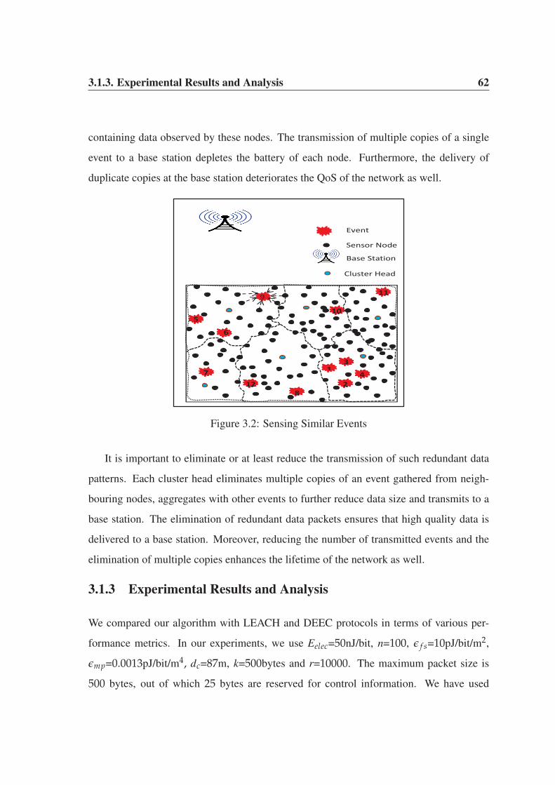
3.1.3. Experimental Results and Analysis 62
containing data observed by these nodes. The transmission of multiple copies of a single
event to a base station depletes the battery of each node. Furthermore, the delivery of
duplicate copies at the base station deteriorates the QoS of the network as well.
1
2
3
4
5
6
7
9
10
8
11
12
Event
Cluster Head
Base Station
Sensor Node
Figure 3.2: Sensing Similar Events
It is important to eliminate or at least reduce the transmission of such redundant data
patterns. Each cluster head eliminates multiple copies of an event gathered from neigh-
bouring nodes, aggregates with other events to further reduce data size and transmits to a
base station. The elimination of redundant data packets ensures that high quality data is
delivered to a base station. Moreover, reducing the number of transmitted events and the
elimination of multiple copies enhances the lifetime of the network as well.
3.1.3 Experimental Results and Analysis
We compared our algorithm with LEACH and DEEC protocols in terms of various per-
formance metrics. In our experiments, we use Eelec=50nJ/bit, n=100, ε f s=10pJ/bit/m2,
εmp=0.0013pJ/bit/m4, dc=87m, k=500bytes and r=10000. The maximum packet size is
500 bytes, out of which 25 bytes are reserved for control information. We have used

3.1.3. Experimental Results and Analysis 63
Matlab 2011a for creating simulation environment in a 100×100 square meter area under
Windows 7 platform. A detailed analysis of various performance metrics such as network
lifetime, data aggregation, and quality of the aggregated data is presented here.
3.1.3.1 Lifetime of the Network
Lifetime of a network is measured in terms of stability period and instability region. Sta-
bility period is the point in time when the first node dies in the network. Instability region
is the point in time when the last node dies in the network. In [125], it was assumed that the
instability region is reached after 97% of the nodes die, because it becomes very difficult
to form clusters as insufficient nodes remain in the network. In Fig. 3.3, we compare our
proposed routing algorithm with LEACH and DEEC protocols in terms of stability period
and instability region.
Figure 3.3: Lifetime of the Network
In our proposed scheme, the inclusion of Econ in Equation 3.5 prohibits lower energy
nodes from being elected as cluster heads. The residual energy of each node plays a vital
role in the cluster head selection and nodes having higher residual energy take preference
over low energy nodes during cluster head selection. In our proposed scheme, a near-
optimal percentage of cluster heads in each round restricts the resource-intensive tasks

3.1.3. Experimental Results and Analysis 64
to fewer nodes which in turns influence the overall network lifetime. On the other hand,
LEACH protocol randomly elects cluster heads irrespective of their residual energy values.
Unlike LEACH and our proposed scheme, DEEC protocol is a heterogeneous cluster-based
hierarchical routing protocol in which 20% of the nodes have higher residual energy at the
time of network deployment. As a result, the network operates for a longer duration in
DEEC protocol which prolongs the instability region.
3.1.3.2 Data Aggregation
In cluster-based hierarchical networks, local data aggregation and fusion is performed by
each cluster head to avoid the transmission of redundant data. The total amount of data
aggregated by each cluster head and the base station over the span of network lifetime is
shown in Fig. 3.4.
12109 8312
106613 106806
0
20000
40000
60000
80000
100000
120000
LEACH Proposed Approach
Num
ber o
f Dat
a Pa
cket
s
Base Station Cluster Heads
Figure 3.4: Data Aggregation
The performance of any data aggregation technique can be judged by the number of
packets received at the cluster head and a base station. During the course of network
lifetime, the cluster heads in our proposed scheme receive 106806 packets in comparison
to 106613 packets in LEACH protocol. After data aggregation, fusion and elimination of
redundant data packets, the data is further transmitted to a base station. In our approach,

3.1.3. Experimental Results and Analysis 65
there are 8312 data packets received at the base station in comparison to 12109 data packets
in LEACH protocol. In comparison to LEACH protocol, our proposed algorithm transmits
much lower number of packets to the base station. This is because the duplicate packets
are refrained from transmission to a base station by each cluster head. The use of an
efficient data aggregation technique at the cluster heads not only eliminates or reduces the
transmission of duplicate packets but also reduces the energy consumption of the nodes
which further prolongs the lifetime of a network.
3.1.3.3 Quality of Data
Quality of data is a percentage value which depends on data aggregation. It is calculated
as sum of packets delivered at the base station to the sum of packets received at the cluster
heads over the span of network lifetime. In Fig. 3.5, quality of data of our proposed
scheme is compared with LEACH protocol using different energy values for sensor nodes.
11.36
7.78
11.24
7.14
0
2
4
6
8
10
12
LEACH Proposed Approach
Quali
ty o
f Dat
a (%)
Half Joule One Joule
Figure 3.5: Quality of Data
For a network of 100 nodes, where each node has half joule of energy, quality of data
is 7.78% for our scheme and 11.36% for LEACH protocol. It means that for every 100
packets, only 7.78 packets on average are transmitted by each cluster head to a base station
in our proposed scheme and 11.36 packets in LEACH protocol. For a similar network size

3.2. A Centralized Energy Evaluation Model 66
with one joule of nodes, quality of data is 11.24% for LEACH protocol and 7.14% for our
proposed scheme. The quality of data improves with the increase of residual energy of the
nodes. Lower the percentage value, higher will be the quality of data and efficient will
be data aggregation at cluster heads. Moreover, low percentage values prolong network
lifetime because less number of packets are transmitted to a base station which reduces the
energy consumption, data processing and communication bandwidth.
3.2 A Centralized Energy Evaluation Model
In Section 3.1, we briefly explained our randomly distributed cluster-based hierarchical
routing algorithm. Although, our proposed scheme is capable to enhance network lifetime
and quality of data, however, it does not guarantee an optimal percentage of cluster heads
in each round. It is a best-effort algorithm which tries to elect a near-optimal percentage of
cluster heads in each round. In other words, the average percentage of cluster heads elected
over a certain number of rounds remains optimal, but in each round, an optimal percentage
is not guaranteed. This is because the threshold Equation 3.5 for cluster head selection is
probabilistic in nature and depends on a random number generation as explained earlier.
To guarantee an optimal percentage of cluster heads in each round, a centralized se-
lection mechanism is required. A central entity such as a base station elects cluster heads
for each round. Nodes are no longer required to generate random numbers and the prob-
abilistic threshold value of Equation 3.5 has no further influence in the cluster head se-
lection. Base station uses the residual energy and location information of each node to
elect cluster heads. In the existing centralized cluster-based hierarchical routing proto-
cols [126] [67] [127] [66], each node is required to transmit its location information and
residual energy to a base station at the beginning of each round. Although, the exist-
ing protocols result in a near-optimal election of cluster heads but these protocols are not
energy-efficient on part of each node. The transmission of residual energy and location in-
formation in each round is a burden on resource-starved sensor nodes. Furthermore, these
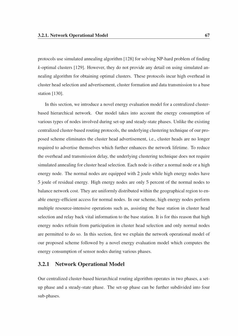
3.2.1. Network Operational Model 67
protocols use simulated annealing algorithm [128] for solving NP-hard problem of finding
k-optimal clusters [129]. However, they do not provide any detail on using simulated an-
nealing algorithm for obtaining optimal clusters. These protocols incur high overhead in
cluster head selection and advertisement, cluster formation and data transmission to a base
station [130].
In this section, we introduce a novel energy evaluation model for a centralized cluster-
based hierarchical network. Our model takes into account the energy consumption of
various types of nodes involved during set-up and steady-state phases. Unlike the existing
centralized cluster-based routing protocols, the underlying clustering technique of our pro-
posed scheme eliminates the cluster head advertisement, i.e., cluster heads are no longer
required to advertise themselves which further enhances the network lifetime. To reduce
the overhead and transmission delay, the underlying clustering technique does not require
simulated annealing for cluster head selection. Each node is either a normal node or a high
energy node. The normal nodes are equipped with 2 joule while high energy nodes have
5 joule of residual energy. High energy nodes are only 5 percent of the normal nodes to
balance network cost. They are uniformly distributed within the geographical region to en-
able energy-efficient access for normal nodes. In our scheme, high energy nodes perform
multiple resource-intensive operations such as, assisting the base station in cluster head
selection and relay back vital information to the base station. It is for this reason that high
energy nodes refrain from participation in cluster head selection and only normal nodes
are permitted to do so. In this section, first we explain the network operational model of
our proposed scheme followed by a novel energy evaluation model which computes the
energy consumption of sensor nodes during various phases.
3.2.1 Network Operational Model
Our centralized cluster-based hierarchical routing algorithm operates in two phases, a set-
up phase and a steady-state phase. The set-up phase can be further subdivided into four
sub-phases.

3.2.1. Network Operational Model 68
• Status
• Cluster Head Selection
• Cluster Formation
• Schedule Creation
During status sub-phase, each normal node transmits a status message to it’s nearest
high energy node before the start of each round. This message contains an 8-bit source
ID, 8-bit destination ID and a variable-length residual energy field. The source ID is the
identity of the transmitter node whereas destination ID is the identity of a nearest high
energy node. The frame format of a status message is shown in Fig. 3.6
8 bit 8 bit variable-length
Source ID Distination ID Residual Energy
Figure 3.6: Frame Format of a Status Message
Each high energy node aggregates status messages from its neighbouring normal nodes
and transmits to a base station. Upon transmission to a base station, each high energy node
goes to sleep mode until the beginning of next round. The base station retrieves the source
ID and residual energy from each status message and stores locally within a queue. It then
calculates the average residual energy (Eavg) using Equation 3.6
Eavg =i=n
∑i=1
(Ei
n). (3.6)
where, Ei is the residual energy of a normal node and n is the total number of such
nodes. In our proposed scheme, n is equal to 100.
During cluster head selection sub-phase, an optimal percentage of cluster heads are
elected by the base station. The base station maintains a queue as shown in Fig. 3.7. Any
node having Ei greater than Eavg is eligible for cluster head selection. In Fig. 3.7, the

3.2.1. Network Operational Model 69
value of Eavg is equal to 1.5 joule for the current round. It is highly probable that there
will be a large number of nodes for which Ei is greater than Eavg in each round. All such
nodes are nominated as the possible candidates for cluster heads. If two or more candidates
are located in the same geographical region, they are evaluated according to their residual
energy values and their election as cluster heads in the past 1kopt
rounds. In our network, the
optimal percentage of cluster heads is 4% to 6% in each round for a network of n nodes.
Step a. 1.44 1.67 1.58 1.38 ---- 1.88 1.49 ---- 1.74 1.46 Node Energy Level, Ei
1 2 3 4 ---- 63 64 ---- (n-1 ) n Node Identity
2 3 11 29 44 63 69 (n-1 )
1.67 1.58 1.92 1.77 1.74 1.88 1.66 1.74 Candidates
1.67 1.77 1.74 1.88 1.74 Cluster Heads
2 29 44 63 (n-1 )
1.67Step b.
1Step c.
Figure 3.7: Candidate Nodes and Cluster Heads
Among the candidates of Fig. 3.7, nodes 2, 3 and 11 reside in one cluster whereas
nodes 63 and 69 reside in another cluster as shown in Fig. 3.8. Only one candidate in each
cluster is allowed to be elected as cluster head. Among nodes 2, 3 and 11, node 11 has the
highest Ei, however, this node has previously been elected as cluster head in the past 1kopt
rounds which makes it ineligible for the current round. The elimination of node 11 from
cluster head selection paves the way for node 2 and 3 as the possible nominees for cluster
head in the current round. Node 2 takes preference over node 3 for cluster head selection
because the former has higher Ei and has not been elected as cluster head in the past 1kopt
rounds. In the second cluster, the election procedure is rather straightforward. Node 63
has a higher Ei than node 69. Furthermore, it has not been elected previously over the past
1kopt
rounds.
We used the term cluster while referring to Fig. 3.7 and Fig. 3.8 for clarity and simpli-
fication purposes. In reality, there is no such thing like cluster at the time of evaluating Ei
by the base station. Once a base station evaluates the residual energy of each node, only

3.2.1. Network Operational Model 70
High Energy Node Hi h E N d Cluster Head Candidate
2
3 11
63 69
Figure 3.8: Cluster Head Selection
then the cluster heads are selected and clusters are formed. In the beginning, all normal
nodes reside within a region inside a sensor field.
The cluster head selection sub-phase is a complex resource-intensive task which incurs
high processing overhead and network delay. During this phase, the normal nodes and
high energy nodes remain in sleep mode to conserve their battery powers. Once an optimal
percentage of cluster heads are selected for the current round, the base station transmits a
message to each normal node. This message contains ID of each normal node and ID of its
respective cluster head. At this point of time, there are two types of normal nodes within
the network: non-cluster head nodes and cluster head nodes. Non-cluster head nodes are
those normal nodes that participated in cluster head selection but were unable to satisfy
the criteria for selection. The base station assigns a cluster head to each non-cluster head
in order to form a cluster. The non-cluster heads become member nodes of a cluster head
within each cluster. The formation of a cluster around each cluster head signals the end of
cluster formation sub-phase. The direct association of a member node with its respective
cluster head enhances network lifetime because a cluster head is no longer required to
advertise itself. Furthermore, each member node avoids the transmission of join-request

3.2.1. Network Operational Model 71
messages to its cluster head.
The completion of cluster formation sub-phase is initiated by schedule creation sub-
phase. During this sub-phase, each cluster head assigns TDMA slots to its member nodes
which allow them to transmit their data using these slots. Furthermore, the creation of
schedule allows the nodes to remain in sleep mode and wake up only on their allocated
time slots.
The completion of status, cluster head selection, cluster formation and schedule cre-
ation sub-phases signal the end of set-up phase and initiation of a steady-state phase. Dur-
ing steady-state phase, each member node collects data according to a predefined condition
and transmits to its cluster head using the allocated TDMA slots. When all the member
nodes within each cluster have transmitted their data, the cluster heads perform necessary
signal processing to eliminate redundant data packets. Because multiple cluster heads are
involved during this process, it would be a resource-consuming task if all these nodes trans-
mit their aggregated data directly to a base station. To reduce their energy consumption,
one of the cluster head is elected as a leader node which collects data from other cluster
heads as shown in Fig. 3.9.
Leader
Figure 3.9: Data Transmission to a Base Station

3.2.1. Network Operational Model 72
The leader node further aggregates the incoming data from the remaining cluster heads
and transmits to a base station. The task performed by a leader node is resource-consuming
and as a result the cluster heads take turn to become a leader node in each round. Among
the cluster heads, the one having the largest residual energy in a particular round is elected
as a leader node. The completion of set-up phase and steady-state phase is coined as one
complete round as previously discussed. After the completion of steady-state phase, status
messages are transmitted again and a new round starts. The complete set of operations
performed during each round is shown in the flowchart of Fig. 3.10.
Figure 3.10: Flowchart of Set-up and Steady-state Phases

3.2.2. Energy Evaluation Model 73
3.2.2 Energy Evaluation Model
During set-up phase and steady-state phase, a series of operations are performed and each
one consumes a considerable amount of energy. The energy consumption of a node de-
pends on the operation it performs at a particular time. A single node may perform one
or more operations in each round. The type of operation along with the distance metric
determine the energy consumption of a node.
During status sub-phase, each normal node transmits its location information and resid-
ual energy to a nearest high energy node. The amount of energy consumed by a normal
node (Estatus) during this sub-phase is calculated using Equation 3.7.
Estatus(m, d) = mEelec + mε f sd2HEN, dHEN < dc. (3.7)
Here, m is the size of message and dHEN is the distance between a normal node and the
nearest high energy node. Because, our network model uses a (100 × 100) square meter
area, it is most likely that a normal node is within the free-space range of a high energy
node.
Each high energy node receives status messages from multiple neighbouring normal
nodes and transmits to a base station. The amount of energy consumed by a high energy
node (EHEN) during status sub-phase is calculated using Equation 3.8.
EHEN(m, d) =
⎧⎪⎨⎪⎩
mEelecx + mε f s d2BS, dBS < dc,
mEelecx + mεmp d4BS, dBS ≥ dc.
(3.8)
Here, x is a subset of normal nodes communicating with a particular high energy node, ∀x ∈ n ∧ x < n and dBS is the distance between a high energy node and the base station. If
the base station is located at a distance less than dc, free-space propagation model is used,
otherwise, multipath ground propagation model is used.

3.2.2. Energy Evaluation Model 74
When the base station selects an optimal percentage of cluster heads, it advertises them
to all the normal nodes. Each cluster head collects data within its cluster and transmits to
the base station using a two-hop communication link. The energy consumed by a cluster
head (ECH) is calculated using Equation 3.9.
ECH(m, d) =
⎧⎪⎨⎪⎩
mEelec(n
kopt) + mEDA(
nkopt
) + mε f sd2LN, dLN < dc,
mEelec(n
kopt) + mEDA(
nkopt
) + mεmpd4LN, dLN ≥ dc.
(3.9)
Here, kopt is the optimal number of clusters which is always equal to the number of cluster
heads because, there is one cluster head per cluster and dLN is the distance between a
cluster head and a leader node.
We used balanced-clustering technique [131] to establish nearly equal-sized clusters.
The base station knows the location of each node and always tries to select cluster heads
which are easily accessible to member nodes provided that such cluster heads satisfy the
selection criteria. The base station tries its best to distribute equal load in each cluster,
i.e., 20 nodes per cluster for a network of 100 nodes. Using these calculations, the value
of kopt is 5 for a network of 100 nodes. The use of balanced-clustering technique enables
our proposed algorithm to elect an optimal number of clusters and cluster heads in most
of the round over the span of network lifetime. Each cluster head consumes energy in data
processing (Eelec), data aggregation within its cluster (EDA) and transmission to a leader
node (dLN).
In Equation 3.9, the cluster heads only perform data processing, data aggregation and
transmission to a leader node. They were not assumed to sense data within their respective
clusters, a role similar to the member nodes. However in case, if the cluster heads sense
the data as well, their energy consumption is much higher. This is due to the fact that each
cluster head not only collects and transmits data from member nodes but also senses its
neighbourhood for data collection. Furthermore, each cluster head aggregates its own data
with the data of member nodes. The energy consumption of each sensing cluster head is

3.2.2. Energy Evaluation Model 75
computed using Equation 3.10.
ESensing−CH(m, d) =
⎧⎪⎪⎪⎪⎪⎪⎪⎪⎨⎪⎪⎪⎪⎪⎪⎪⎪⎩
αI + mEelec(n
kopt) + mEDA(
nkopt
)+
mε f sd2LN, dLN < dc,
αI + mEelec(n
kopt) + mEDA(
nkopt
)+
mεmpd4LN, dLN ≥ dc.
(3.10)
where, α is the amount of energy consumed by a cluster head in sensing a single bit
and I is the total number of bits in the sensed message.
The amount of energy consumed by a member node (Emember) within its cluster is
computed using Equation 3.11.
Emember = αI + mEelec + mε f sd2CH, dCH < dc. (3.11)
Here, dCH is the distance between a member node and its cluster head. The member node
is in close neighbourhood of a cluster head, therefore, free-space propagation model is an
obvious choice. Once each cluster head collects data from its member nodes, a leader node
is elected by them to transmit their data to a base station. The amount of energy consumed
by a leader node (ELN) is computed using Equation 3.12.
ELN(m, d) =
⎧⎪⎪⎪⎪⎪⎪⎪⎪⎪⎪⎪⎪⎨⎪⎪⎪⎪⎪⎪⎪⎪⎪⎪⎪⎪⎩
mEelec(n
kopt) + mEDA(
nkopt
)+
mEDA(∑kopt−1i=1 CHi) + mε f sd2
BS, dBS < dc,
mEelec(n
kopt) + mEDA(
nkopt
)+
mEDA(∑kopt−1i=1 CHi) + mεmpd4
BS, dBS ≥ dc.
(3.12)
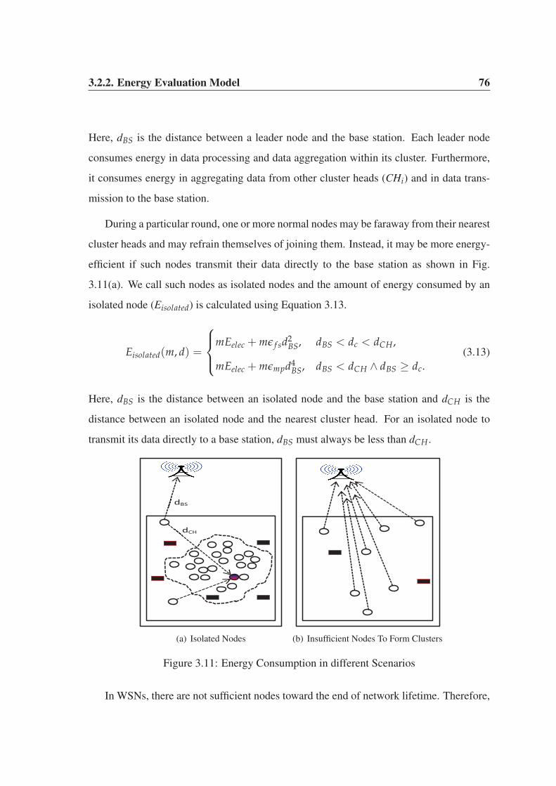
3.2.2. Energy Evaluation Model 76
Here, dBS is the distance between a leader node and the base station. Each leader node
consumes energy in data processing and data aggregation within its cluster. Furthermore,
it consumes energy in aggregating data from other cluster heads (CHi) and in data trans-
mission to the base station.
During a particular round, one or more normal nodes may be faraway from their nearest
cluster heads and may refrain themselves of joining them. Instead, it may be more energy-
efficient if such nodes transmit their data directly to the base station as shown in Fig.
3.11(a). We call such nodes as isolated nodes and the amount of energy consumed by an
isolated node (Eisolated) is calculated using Equation 3.13.
Eisolated(m, d) =
⎧⎪⎨⎪⎩
mEelec + mε f sd2BS, dBS < dc < dCH,
mEelec + mεmpd4BS, dBS < dCH ∧ dBS ≥ dc.
(3.13)
Here, dBS is the distance between an isolated node and the base station and dCH is the
distance between an isolated node and the nearest cluster head. For an isolated node to
transmit its data directly to a base station, dBS must always be less than dCH.
dCH
dBS
(a) Isolated Nodes
(b) Insufficient Nodes To Form Clusters
Figure 3.11: Energy Consumption in different Scenarios
In WSNs, there are not sufficient nodes toward the end of network lifetime. Therefore,

3.3. Summary 77
it may not be possible to form one or more clusters. In that case, each normal node trans-
mits its data directly to the base station as shown in Fig. 3.11(b). The amount of energy
consumed by each node (Eend) is calculated using Equation 3.14.
Eend(m, d) =
⎧⎪⎨⎪⎩
mEelec + mε f sd2BS, dBS < dc,
mEelec + mεmpd4BS, dBS ≥ dc.
(3.14)
The amount of energy consumed in any particular round (Eround) is calculated using
Equation 3.15.
Eround = Estatus + EHEN + ECH + Emember + ELN + Eisolated (3.15)
Finally, the total amount of energy (ETotal) consumed over the span of network lifetime is
computed using Equation 3.16.
ETotal =i=r
∑i=1
Eround +i=r
∑i=1
Eend (3.16)
Here, r is the total number of rounds over which a network operates. When there are one
or more clusters within a network, Eround is the end product. However, towards the end of
network lifetime, there are not sufficient nodes to form one or more clusters in any round
and the end result is Eend. The sum of Eround and Eend result in the total amount of energy
consumed over the span of network lifetime.
3.3 Summary
This chapter has two major objectives. First, a randomly distributed cluster-based hierar-
chical algorithm was proposed to elect a near-optimal percentage of cluster heads. The
proposed routing algorithm elects cluster heads based on their residual energy consump-
tion. The goal of the routing algorithm was to enhance network lifetime and quality of data

3.3. Summary 78
delivered at the base station. Secondly, a centralized cluster-based hierarchical algorithm
was proposed in which the base station elects an optimal percentage of cluster heads in
each round. Unlike the existing centralized approaches, our algorithm does not require
cluster head advertisement and join-request message transmissions. Once a centralized se-
lection of cluster heads is performed, an energy evaluation model is developed which takes
into account the energy consumption of the nodes during various phases and sub-phases.

Chapter 4
Energy-efficient Cluster-based
Congestion Control Algorithm
In WSNs, the data generated by heterogeneous applications differ from each other in terms
of data rate, transmission priority, bandwidth requirement, delay-tolerance and acceptable
packet loss [132]. It is necessary to meet the individual requirements of each data type. In
a cluster-based hierarchical WSN, as the nodes move across the cluster field, it is highly
probable that the number of nodes in a particular cluster may exceed the maximum thresh-
old limit for that cluster. Unbalanced clusters cause congestion, thereby resulting in packet
loss, latency, blockage of new connections and QoS degradation. Congestion affects both
static and mobile WSNs. Time-critical applications experience severe setbacks due to con-
gestion because time-stamped data need to be routed to a base station immediately. Minor
delays in transmission will make the data useless and redundant. Network congestion is
mitigated by increasing the capacity of the links or by controlling the data rate of each
node [133]. In this chapter, a novel priority-based application-specific congestion control
clustering (PASCCC) protocol is proposed, which integrates mobility and heterogeneity of
the nodes to detect congestion in a network. PASCCC decreases the duty-cycle of each
node by maintaining threshold levels for various applications. The transmitter of a sensor

4.1. The PASCCC Protocol 80
node is triggered when the reading of a captured event exceeds a specific threshold value.
Time-critical packets are prioritized during congestion in order to maintain their timeliness
requirements. The cluster heads ensure coverage fidelity by prioritizing the packets of dis-
tant nodes over those of nearby nodes. A novel queue scheduling mechanism is proposed
for cluster heads to achieve coverage fidelity, which ensures that the extra resources con-
sumed by distant nodes are utilized effectively. PASCCC uses the randomly distributed
cluster-based hierarchical algorithm as the underlying platform for its operation. PASCCC
is based on our work published in [134] and operates on the network layer of WSN stack.
The rest of the chapter is organized as follows. In Section 4.1, various features of the
deployed nodes are discussed. In Section 4.2, the framework of PASCCC is presented
followed by its operational mechanism in Section 4.3. Finally, we conclude the chapter by
providing experimental results in Section 4.4.
4.1 The PASCCC Protocol
In this section, we provide a brief description of the nodes used by our energy-efficient
PASCCC protocol. To the best of our knowledge, PASCCC is the first protocol of its kind
to consider mobility, heterogeneity, congestion detection and mitigation using a cluster
hierarchy. We make the following assumptions about the operational capabilities of the
nodes.
• Nodes are deployed randomly in the field with a different set of energy values.
• Nodes are capable of adjusting their transmission power in order to reach a far distant
cluster head during a specific round.
• A small percentage of advanced nodes are used to provide network stability towards
the end of network lifetime. These nodes have higher energy as compared to normal
nodes and are more frequently elected as cluster heads.
• The location of a base station is not fixed and it can be either within or outside the
sensor field.

4.2. Framework of PASCCC 81
• Nodes are capable of moving around the sensor field to cover vacant regions using
the random waypoint mobility model [135] with a speed V, where the value of V
ranges between Vmin and Vmax.
The framework of our proposed protocol is discussed in Section 4.2 followed by its
operational mechanism in Section 4.3.
4.2 Framework of PASCCC
In static WSNs, the nodes are confined to specific geographical locations for monitoring
various applications. To balance the network cost, the nodes cover only a subset of sen-
sor field which results in uncovered regions. In these networks, the dynamic nature of
happening events may cause one or more events to go unreported provided they occur in
uncovered regions. Fig. 4.1(a) presents the generic topology of a static WSN where all
the nodes are static, which results in uncovered regions such as region A and region B. If
critical events occur in these regions, they will go unreported, thereby causing important
data loss and degradation of the network quality. Mobile nodes solve this problem by mov-
ing around the field to provide the necessary coverage and connectivity using PASCCC as
shown in Fig. 4.1(b). The nodes are capable of moving around the field if required in
order to cover vacant regions. Mobility ensures complete coverage and connectivity at all
times. Hence, it is less likely that the generated events will go unreported. In PASCCC,
10% of the nodes are advanced. These nodes have higher energy levels as compared to
normal nodes. Normal nodes are represented by “circle”, advanced nodes are represented
by “square” and the base station is represented by “star” as shown in Fig. 4.1(b).
PASCCC is an application-specific protocol. In our scheme, we consider two appli-
cation parameters using PASCCC: temperature and humidity. PASCCC acts as a reactive
protocol for temperature monitoring and as a proactive protocol for humidity monitoring.
In reactive routing protocols, the nodes react immediately to sudden and drastic changes in
the values of sensed events [136]. As a result, these protocols are suitable for time-critical
4.3. PASCCC Operational Mechanism 82
Region B
Region A
(a) Topology of Static WSN
Region A
Region B
(b) Topology of PASCCC
Figure 4.1: Framework of the Proposed Protocol
applications. In proactive routing protocols [61], the nodes switch on their transmitters,
sense the environment and report the sensed data periodically to a base station. These
protocols are suitable for applications that require periodic data transmission.
4.3 PASCCC Operational Mechanism
A detailed description of PASCCC is provided here in terms of application support, con-
gestion detection and mitigation and the underlying queuing model.
4.3.1 PASCCC: An Application-specific Protocol
PASCCC supports two different types of application, thus different sets of priorities and
timeliness requirements are maintained for the packets. Each node is equipped with two
sensors to monitor the temperature and humidity packets. Our protocol operates under the
following assumptions.
• The nodes sense and capture humidity packets continuously and transmit them to
their respective cluster heads.
• During congestion, humidity packets are dropped to reduce the level of congestion.
• Nodes turn on their transmitters and start sensing temperature events after a certain

4.3.1. PASCCC: An Application-specific Protocol 83
threshold value is reached.
In terms of priority, humidity packets have a lower priority and they can tolerate some
delay, packet loss and degradation in their QoS. By contrast, temperature packets have a
higher priority and they need to be reported immediately to a base station. These pack-
ets are time-stamped. Even a minor delay in their transmission will make them useless
and redundant. During congestion, the temperature packets are prioritized over humidity
packets. To capture temperature packets, the nodes turn on their temperature sensors only
when the hard threshold (HT) is reached [136]. We set the value of HT to 50 0C. In our
proposed scheme, HT is the minimum temperature reading at which the sensors operate by
capturing the packets. Any value less than HT will not be able to trigger the temperature
sensors. This value is stored in a local variable inside the memory of each node, which we
call the sensed value (SV). If a node has to transmit data to its cluster head more than once
in the current round, it can only do so if its sensed value is greater than or equal to the soft
threshold (ST). ST represents a small change in the value of the sensed data, which triggers
the transmitter of each temperature sensor to capture the packets and report them to their
respective cluster heads. In PASCCC, the value of ST is 2 0C. Thus, each temperature sen-
sor will trigger for the first time at 50 0C. On the next occasion, it will only trigger when
the temperature reading is at least 52 0C in the current round. This new value is then stored
in SV. The reason for using the soft threshold is to reduce data redundancy in the current
round because an end user is only interested in disjoint sets of data patterns collected from
sensor field. In the absence of ST, the nodes will transmit similar data packets, which will
then impose an extra burden on energy-starved sensor nodes.
It should be noted that PASCCC is designed to operate in a temperature range of 50 0C
to 100 0C. Humidity, on the other hand, has a lower priority and is measured as the amount
of moisture content in the air. Humidity is a percentage value. HT and ST are not applicable
to humidity packets and they are transmitted immediately upon detection during normal
network load. However, during network congestion, they are dropped to pave the way for
highly-prioritized temperature packets. Because it depends on a threshold value, PASCCC

4.3.2. PASCCC: Congestion Detection and Mitigation 84
is suitable for bush fire monitoring [85] and similar applications where temperature is the
main parameter used to measure critical events. When the temperature in the bush rises
above a certain threshold value, the nodes turn on their transmitters and report the captured
events to a base station. These events are prioritized in order to prevent any catastrophic
consequences.
4.3.2 PASCCC: Congestion Detection and Mitigation
PASCCC uses the balanced clustering technique [131] to ensure that each round results in
an equal number of nodes in each cluster. This technique is a rather idealistic approach to
cluster formation because it tries its best to achieve its goal, but balanced clusters cannot
be guaranteed in each round. In addition, PASCCC inherits mobility features to cover
the vacant regions. Mobility ensures complete coverage and connectivity at all times,
but it also yields unbalanced clusters in various rounds throughout the network lifetime.
This problem is common in static clustering protocols as well such as LEACH and its
variants, which imposes an extra burden on the cluster heads in terms of communication,
computation, and data aggregation. Congestion arises in these circumstances, thereby
causing packet loss, delay, blocking of new connections and degradation of the QoS.
During congestion, highly-prioritized temperature packets are routed to the base sta-
tion to maintain the integrity of their time-stamps while humidity packets are dropped to
reduce the level of congestion. Congested clusters are shown in Fig. 4.2(a), where clus-
ters 1 and 3 are overcrowded, thereby causing extra resource utilization. Thus, nodes are
prevented from capturing humidity packets in these clusters. PASCCC reduces congestion
by a considerable degree because the temperature packets are only captured when a spe-
cific threshold is met and the humidity packets are dropped during congestion. Fig. 4.2(b)
shows the location of congested regions, which are represented by the x and y coordinates
in the sensor field. In PASCCC protocol, the duty-cycling of each node depends on the
congested regions and predefined threshold limits.

4.3.2. PASCCC: Congestion Detection and Mitigation 85
1
5 3
4
2
(a) Congestion at the Cluster Level
0 10 20 30 40 50 60 70 80 90 1000
10
20
30
40
50
60
70
80
90
100
X−axis
Y−a
xis
g
(b) Congested Region Locations
Figure 4.2: Congestion Detection and Mitigation
We programmed the nodes by modifying the balanced clustering technique which as-
sumes that all clusters are supposed to have an equal number of member nodes. This
technique depends on the value of optimal percentage of cluster heads (kopt). In PASCCC,
the nodes are capable of moving around the field to cover vacant regions to prevent valu-
able data losses. However, the mobility of the nodes may result in unbalanced clusters in
which some clusters will have more member nodes as compared to other. In addition, the
nodes move from one cluster to another during various rounds of operation, which may re-
sult in overcrowded clusters. During the set-up phase, each cluster head allocates TDMA
slots to its member nodes. The number of assigned slots within each cluster depends on
the total number of join-request messages sent by the member nodes. If these request mes-
sages exceed the threshold limit for a specific cluster, the cluster head piggybacks one bit
field in each time slot for its member nodes. After receiving the piggybacked time slots,
the nodes in that specific cluster turn off their humidity sensors. The piggybacked time
slots are used to prevent congestion in this manner. These time slots are used only when
each member node receives indications from its specific cluster head about the degree of
congestion within its cluster.
Congestion and unbalanced clustering lead to sparse distributions of nodes in other
clusters. Hence, the network resources are not fully utilized, thereby causing poor data ag-
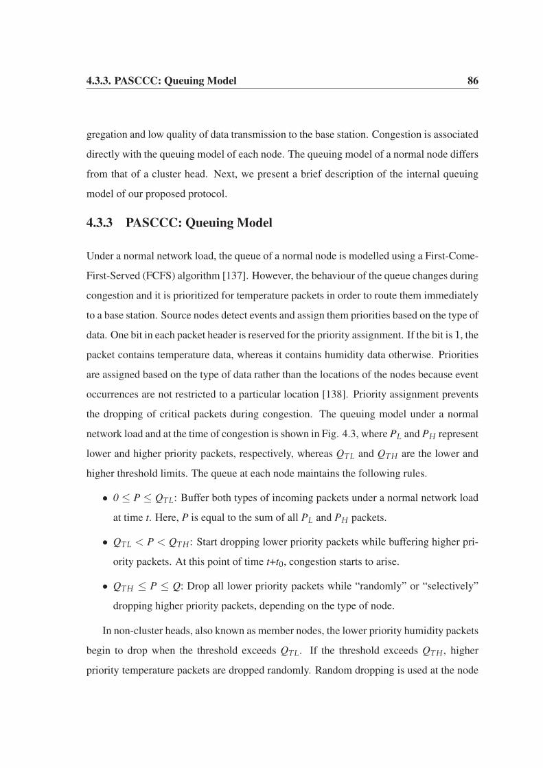
4.3.3. PASCCC: Queuing Model 86
gregation and low quality of data transmission to the base station. Congestion is associated
directly with the queuing model of each node. The queuing model of a normal node differs
from that of a cluster head. Next, we present a brief description of the internal queuing
model of our proposed protocol.
4.3.3 PASCCC: Queuing Model
Under a normal network load, the queue of a normal node is modelled using a First-Come-
First-Served (FCFS) algorithm [137]. However, the behaviour of the queue changes during
congestion and it is prioritized for temperature packets in order to route them immediately
to a base station. Source nodes detect events and assign them priorities based on the type of
data. One bit in each packet header is reserved for the priority assignment. If the bit is 1, the
packet contains temperature data, whereas it contains humidity data otherwise. Priorities
are assigned based on the type of data rather than the locations of the nodes because event
occurrences are not restricted to a particular location [138]. Priority assignment prevents
the dropping of critical packets during congestion. The queuing model under a normal
network load and at the time of congestion is shown in Fig. 4.3, where PL and PH represent
lower and higher priority packets, respectively, whereas QTL and QTH are the lower and
higher threshold limits. The queue at each node maintains the following rules.
• 0 ≤ P ≤ QTL: Buffer both types of incoming packets under a normal network load
at time t. Here, P is equal to the sum of all PL and PH packets.
• QTL < P < QTH: Start dropping lower priority packets while buffering higher pri-
ority packets. At this point of time t+t0, congestion starts to arise.
• QTH ≤ P ≤ Q: Drop all lower priority packets while “randomly” or “selectively”
dropping higher priority packets, depending on the type of node.
In non-cluster heads, also known as member nodes, the lower priority humidity packets
begin to drop when the threshold exceeds QTL. If the threshold exceeds QTH, higher
priority temperature packets are dropped randomly. Random dropping is used at the node
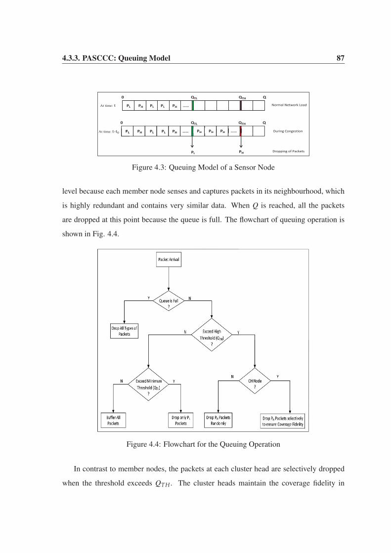
4.3.3. PASCCC: Queuing Model 87
PL PH PL PL PH ……
0 QTL QTH Q
PL PH PL PL PH …… PH PH PH ……
0 QTL QTH Q
At time: t
PL At time: t+t0
PL PH Dropping of Packets
Normal Network Load
During Congestion
Figure 4.3: Queuing Model of a Sensor Node
level because each member node senses and captures packets in its neighbourhood, which
is highly redundant and contains very similar data. When Q is reached, all the packets
are dropped at this point because the queue is full. The flowchart of queuing operation is
shown in Fig. 4.4.
Figure 4.4: Flowchart for the Queuing Operation
In contrast to member nodes, the packets at each cluster head are selectively dropped
when the threshold exceeds QTH. The cluster heads maintain the coverage fidelity in

4.4. Experimental Results and Analysis 88
sensor field [139]. Distant nodes in each cluster consume more energy to transmit their
data to their respective cluster heads. Thus, the prioritized packets of these nodes are
routed immediately due to the time elapsed in their time-stamps, which will expire earlier
compared with the nearby nodes. Therefore, the distance of a node from the cluster head
plays an important role in queue scheduling of that node. In WSNs, distant nodes at
remote locations capture highly sensitive data compared with nearby nodes. Thus, each
cluster head evaluates critical temperature packets based on the distance of the source
nodes from itself. Packets of remote nodes are forwarded to the base station, whereas those
of nearby nodes are dropped when the threshold exceeds QTH. The temperature readings
of incoming packets from remote nodes and nearby nodes must be in close proximity
of each other, otherwise, the above condition cannot be applied. Priority assignment is
applied due to the application-specific nature of PASCCC, but the data delivery timeliness
and QoS requirements vary among applications. More specifically, applications have a
different quality of information [140].
4.4 Experimental Results and Analysis
In this section, we make comparison between PASCCC protocol and other routing proto-
cols in terms of various performance metrics. We performed our evaluation and analysis
using the same parameters of the randomly distributed cluster-based hierarchical algorithm
of Chapter 3. Therefore, comparisons were made between PASCCC and existing cluster-
based hierarchical routing protocols in terms of network lifetime, energy consumption,
data transmission and quality of data. In addition, a probabilistic approach was used to de-
tect congestion, which was then validated based on the simulation results. Matlab R2011a
was used as the simulation tool under Windows 7 platform. The nodes were deployed in a
100 × 100 square meter area with sensor nodes randomly distributed.

4.4.1. Lifetime of the Network 89
4.4.1 Lifetime of the Network
The lifetime of a network is measured in terms of stability period and instability region.
We calculated the stability period and instability region as shown in Fig. 4.5.
916 943 879
1641 1851
2965
1602
9214
0
2000
4000
6000
8000
10000
LEACH SEP LEACH-Mobile PASCCC
Num
ber o
f Rou
nds
Stability Period Instability Region
Figure 4.5: Lifetime of the Network
In terms of stability period and instability region, PASCCC performs much better as
compared to other protocols because of its application-specific nature, which reduces the
duty-cycling of each node. On the other hand, SEP [141] has a better performance as com-
pared to LEACH [61] and LEACH-Mobile [142] because of its heterogeneous collection
of nodes, which extends the lifetime of the network. LEACH-Mobile handles constantly
moving nodes, which consume more energy and the lifetime of the network is significantly
reduced. Unlike LEACH-Mobile, our proposed protocol provides mobility on-demand ba-
sis to cover vacant regions left behind by the dying nodes.
4.4.2 Residual Energy
Energy consumption of the nodes influences the lifetime of a network. Higher the residual
energy consumption, shorter will be the lifetime of a network. In Fig. 4.6, we compare

4.4.3. Data Transmission 90
PASCCC protocol with LEACH and its variants in terms of residual energy consumption.
In PASCCC, the temperature sensors remain in the sleep mode until specific thresholds
trigger their transmitters. Humidity sensors also enter the sleep mode after congestion is
detected. In other protocols, the nodes have higher duty-cycles and they consume higher
amount of energy during processing and communication. PASCCC and SEP protocols
contain normal nodes and advanced nodes. The normal nodes are equipped with 0.5 joule
while the advanced nodes are equipped with 1 joule of energy. PASCCC utilizes limited
energy of the nodes efficiently compared with LEACH, SEP and LEACH-Mobile pro-
tocols. The energy consumption of the existing protocols exhibits an overlapping trend,
although SEP produces a slight improvement in the instability region.
0
10
20
30
40
50
60
1 501 1001 1501 2001 2501 3001 3501
Re
sid
ual
En
erg
y C
on
sum
pti
on
Number of Rounds
SEP
LEACH
PASCCC
LEACH-Mobile
Figure 4.6: Residual Energy Consumption (in Joules)
4.4.3 Data Transmission
The number of transmitted packets affects the energy consumption and network conges-
tion. Higher volume of data traffic increases the possibility of congestion which can ul-
timately lead to network failure. Hence, in this thesis, our aim is to limit redundant data
transmission to the base station. Fig. 4.7 shows the total number of data packets delivered

4.4.3. Data Transmission 91
at the cluster heads and base station over the span of network lifetime. PASCCC has a
lower duty-cycle compared with the existing cluster-based routing protocols. As a result,
the total amount of transmitted data is significantly lower. For temperature monitoring,
PASCCC captures the data only when HT and ST are met. For humidity monitoring, it
drops humidity packets when congestion is detected and keeps the humidity sensor of a
node in sleep mode which reduces the amount of captured data. The use of HT, ST and
keeping the humidity sensors in sleep mode not only reduces the amount of transmitted
data but also enhances the network lifetime. In Fig. 4.7, PASCCC delivers 148232 packets
to the cluster heads and 3922 packets to the base station. In comparison, LEACH, SEP and
LEACH-Mobile deliver much higher number of packets to the cluster heads and the base
station.
9573 9496 9499 3922
210258 211306 211320
148232
0
50000
100000
150000
200000
250000
LEACH SEP LEACH-Mobile PASCCC
Num
ber o
f Pac
kets
Packets to Base Station Packets to Cluster Heads
Figure 4.7: Data Transmission to Cluster Heads and Base Station
Using Fig. 4.7, we computed the quality of data for these protocols. Recall that the
quality of data is a percentage value and is calculated as the sum of packets delivered at
the base station to the sum of packets delivered at the cluster heads. The quality of data
for PASCCC is 2.64, LEACH-Mobile is 4.49, SEP is 4.49 and LEACH is 4.55 respec-
tively. These values indicate that PASCCC performs much better as compared to existing

4.4.4. Causes of Congestion 92
protocols due to its efficient duty-cycling and threshold-based operational mechanism.
4.4.4 Causes of Congestion
Based on our simulation results, we identified the nodes that caused congestion. Mobility
of the nodes results in an unequal distribution of nodes in one or more clusters which
causes network congestion. In a cluster-based hierarchical protocol, each node must be
elected as cluster head once every 1kopt
rounds [122]. In addition, each cluster has exactly
one cluster head so the number of clusters is always equal to the number of cluster heads
in each round. If there are N nodes in the network and the optimal number of clusters is
kopt, then the number of nodes in each cluster is calculated using Equation 4.1.
Cn =N
kopt. (4.1)
The probability of a node X to be elected as cluster head throughout the network lifetime
is calculated using Equation 4.2.
XCH = kopt × rtotal. (4.2)
Here, XCH is the number of times X is elected as a cluster head during its lifetime and rtotal
is the total number of rounds during which XCH is calculated.
Based on Equations 4.1 and 4.2, the number of nodes associated with any cluster head
during its lifetime is calculated using Equation 4.3.
n=N
∑n=1
CHn = (N
kopt− 1)× XCH. (4.3)
Here, n is any node that wants to become a cluster head. According to the balanced clus-
tering technique [131], each cluster has an equal number of nodes, Nkopt
. Any value greater
than that obtained using Equation 4.1 will result in congestion at the cluster level.

4.5. Summary 93
We evaluated Equations [4.1-4.3] using N=100, rtotal=1000, and kopt=5. Based on
these parameters, any cluster head associated with more than 950 nodes (threshold level)
throughout the network lifetime will cause congestion, as shown in Fig. 4.8(a). The num-
ber of humidity packets dropped during congestion in the first 1000 rounds is shown in
Fig. 4.8(b).
(a) Nodes Associated with Each Cluster Head
0 200 400 600 800 1000 12000
1
2
3
4
5
6
7
8
9
Number of Rounds
Packets
Count
y g g
(b) Dropping of Humidity Packets
Figure 4.8: Congestion Detection and Mitigation
4.5 Summary
In this chapter, we used the randomly distributed cluster-based hierarchical algorithm of
Chapter 3 to design a novel congestion detection and mitigation protocol for cluster-based
hierarchical WSNs. The proposed PASCCC protocol has the following distinctive features.
1. PASCCC provides an on-demand network mobility to cover vacant regions within a
sensor field.
2. PASCCC is an application-specific and priority-driven protocol which treats two
different monitoring applications based on their levels of assigned priorities.
3. At the time of network congestion, higher priority temperature packets are routed

4.5. Summary 94
from congested clusters to the base station while lower priority humidity packets are
instantly dropped to mitigate the level of congestion.
4. A novel queuing model is designed which drops the packets based on the assigned
priority levels, threshold levels and types of nodes.
PASCCC protocol uses threshold parameters to efficiently schedule the duty-cycling of
each node. The threshold-specific nature of PASCCC reduces the energy consumption of
the nodes in various network operations. As a result, PASCCC is suitable for monitoring a
wide range of threshold-specific applications such as forest wildfire, volcanic eruption, air
pollution and habitat monitoring.
In this chapter, we focused on designing an efficient clustering mechanism to detect and
mitigate congestion in a cluster-based hierarchical network. Efficient congestion detection
and mitigation techniques conserve the energy of sensor nodes and enhance the lifetime
of a network. In Chapter 5, we present a Sybil attack detection scheme in a centralized
cluster-based hierarchical network. The proposed detection technique is highly efficient in
term of detection rate, energy consumption and network lifetime. An efficient detection
technique against Sybil attack reduces the number of packets being dropped which literally
means that the number of retransmission attempts are reduced. Ultimately, the energy
consumption is reduced which enhances the lifetime of a network. Moreover, safeguarding
against various threats such as malicious data transmission, alteration of packet sequencing
and fabricated data transmission, also reduces the energy consumption of the nodes.
Chapter 5
Sybil Attack Detection Scheme for a
Cluster-based Hierarchical Network
The presence of low-power lossy links and a hostile deployed environment exposes WSNs
to a wide range of security threats at different layers. Sybil attack is one such threat which
targets the routing layer of WSN. The cluster-based hierarchical protocols operate at the
routing layer which makes them a favourable target for an adversary to launch a Sybil
attack. In this chapter, we propose a lightweight Sybil attack detection scheme for a cen-
tralized cluster-based hierarchical network. The proposed scheme requires coordination
of any two high energy nodes and performs its detection task using signal strength of the
received packets. The goal of our proposed scheme is to prevent Sybil nodes from par-
ticipation in cluster head selection. A single Sybil node can wreak havoc in the network
by forming multiple clusters using its forged identities as separate cluster heads. In Sec-
tion 5.1, we discuss some network assumptions for the proposed scheme. In Section 5.2,
we provide a detailed explanation of our Sybil attack detection scheme which is followed
by the formation of a centralized cluster-based hierarchical network in Section 5.3. This
chapter is based on our work published in [143].
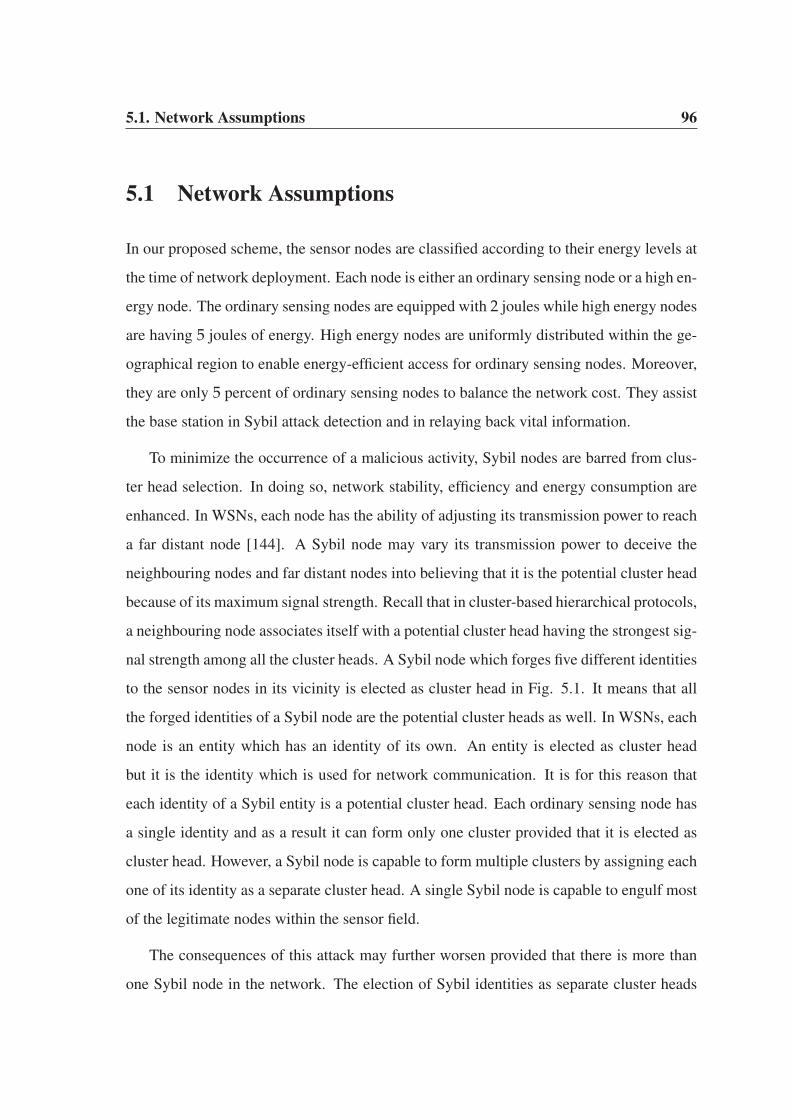
5.1. Network Assumptions 96
5.1 Network Assumptions
In our proposed scheme, the sensor nodes are classified according to their energy levels at
the time of network deployment. Each node is either an ordinary sensing node or a high en-
ergy node. The ordinary sensing nodes are equipped with 2 joules while high energy nodes
are having 5 joules of energy. High energy nodes are uniformly distributed within the ge-
ographical region to enable energy-efficient access for ordinary sensing nodes. Moreover,
they are only 5 percent of ordinary sensing nodes to balance the network cost. They assist
the base station in Sybil attack detection and in relaying back vital information.
To minimize the occurrence of a malicious activity, Sybil nodes are barred from clus-
ter head selection. In doing so, network stability, efficiency and energy consumption are
enhanced. In WSNs, each node has the ability of adjusting its transmission power to reach
a far distant node [144]. A Sybil node may vary its transmission power to deceive the
neighbouring nodes and far distant nodes into believing that it is the potential cluster head
because of its maximum signal strength. Recall that in cluster-based hierarchical protocols,
a neighbouring node associates itself with a potential cluster head having the strongest sig-
nal strength among all the cluster heads. A Sybil node which forges five different identities
to the sensor nodes in its vicinity is elected as cluster head in Fig. 5.1. It means that all
the forged identities of a Sybil node are the potential cluster heads as well. In WSNs, each
node is an entity which has an identity of its own. An entity is elected as cluster head
but it is the identity which is used for network communication. It is for this reason that
each identity of a Sybil entity is a potential cluster head. Each ordinary sensing node has
a single identity and as a result it can form only one cluster provided that it is elected as
cluster head. However, a Sybil node is capable to form multiple clusters by assigning each
one of its identity as a separate cluster head. A single Sybil node is capable to engulf most
of the legitimate nodes within the sensor field.
The consequences of this attack may further worsen provided that there is more than
one Sybil node in the network. The election of Sybil identities as separate cluster heads
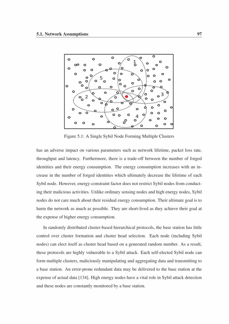
5.1. Network Assumptions 97
1
5
4
2 3
Figure 5.1: A Single Sybil Node Forming Multiple Clusters
has an adverse impact on various parameters such as network lifetime, packet loss rate,
throughput and latency. Furthermore, there is a trade-off between the number of forged
identities and their energy consumption. The energy consumption increases with an in-
crease in the number of forged identities which ultimately decrease the lifetime of each
Sybil node. However, energy-constraint factor does not restrict Sybil nodes from conduct-
ing their malicious activities. Unlike ordinary sensing nodes and high energy nodes, Sybil
nodes do not care much about their residual energy consumption. Their ultimate goal is to
harm the network as much as possible. They are short-lived as they achieve their goal at
the expense of higher energy consumption.
In randomly distributed cluster-based hierarchical protocols, the base station has little
control over cluster formation and cluster head selection. Each node (including Sybil
nodes) can elect itself as cluster head based on a generated random number. As a result,
these protocols are highly vulnerable to a Sybil attack. Each self-elected Sybil node can
form multiple clusters, maliciously manipulating and aggregating data and transmitting to
a base station. An error-prone redundant data may be delivered to the base station at the
expense of actual data [134]. High energy nodes have a vital role in Sybil attack detection
and these nodes are constantly monitored by a base station.

5.2. Sybil Attack Detection 98
In view of the above discussion, we propose a novel Sybil attack detection scheme
for a centralized cluster-based hierarchical network. Initially, high energy nodes identify
Sybil nodes and report them to a base station to avoid their participation in cluster head
selection. It ensures that only legitimate nodes can be elected as cluster heads in each
round. Next, the base station elects an optimal number of cluster heads in each round
based on an average residual energy value.
5.2 Sybil Attack Detection
We use the concept of Received Signal Strength Indicator (RSSI) for detection of Sybil
attack. A variable number of Sybil nodes with multiple forged identities are injected before
the start of each round. Each Sybil node has 2 joules of energy. Both normal nodes and
Sybil nodes are isomorphic in nature, i.e., having similar capabilities in terms of sensing,
processing, communication and broadcasting. The objective of our scheme is to prevent
their participation in cluster head selection. The normal nodes and Sybil nodes transmit
control packets to their two nearest high energy nodes as shown in Fig. 5.2. Each packet
contains the identity and residual energy of the transmitter node. Theorem 5 in [145]
argued that if at least four sensor nodes monitor radio signals from a neighbouring node,
it will not be able to hide its location. However, for a resource-constrained WSN, it is a
computationally complex task which requires abundant of network resources. To reduce
the processing complexity, we propose a lightweight scheme for Sybil attack detection
which requires the coordination of any two high energy nodes.
Suppose that, high energy nodes, hen1 and hen2, receive control packets from node i at
time t1. If the identity of node i in control packets is x, then the RSSI (Rxhen1) is calculated
by hen1 using Equation 5.1.
Rxhen1 =
Ptkdα
hen1. (5.1)
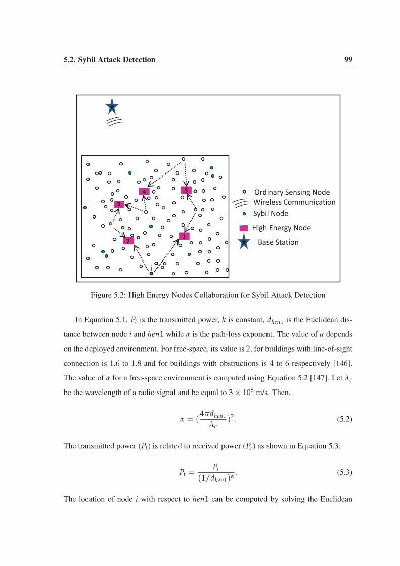
5.2. Sybil Attack Detection 99
1
i
3
4 5
Base Station
Ordinary Sensing Node
High Energy Node
Sybil Node
2
Wireless Communication
Figure 5.2: High Energy Nodes Collaboration for Sybil Attack Detection
In Equation 5.1, Pt is the transmitted power, k is constant, dhen1 is the Euclidean dis-
tance between node i and hen1 while α is the path-loss exponent. The value of α depends
on the deployed environment. For free-space, its value is 2, for buildings with line-of-sight
connection is 1.6 to 1.8 and for buildings with obstructions is 4 to 6 respectively [146].
The value of α for a free-space environment is computed using Equation 5.2 [147]. Let λc
be the wavelength of a radio signal and be equal to 3 × 10⁸ m/s. Then,
α = (4πdhen1
λc)2. (5.2)
The transmitted power (Pt) is related to received power (Pr) as shown in Equation 5.3.
Pt =Pr
(1/dhen1)α. (5.3)
The location of node i with respect to hen1 can be computed by solving the Euclidean

5.2. Sybil Attack Detection 100
distance of Equation 5.4. Euclidean distance enables an ordinary sensing node to locate its
two nearest high energy nodes.
dhen1 =√(xhen1 − xi)2 − (yhen1 − yi)2. (5.4)
Solving Equations [5.2-5.4] and substituting their values in Equation 5.1 enable hen1 to
calculate Rxhen1. At this point, hen1 creates its own control packet and appends the value
of Rxhen1 in it and transmits to its nearest high energy node, hen2. Recall that hen2 has
received a similar control packet from node i at time t1 and has calculated the value of
Rxhen2 using a similar procedure as hen1. Next, hen2 calculates the radio signal strength
ratio as shown in Equation 5.5.
Rxhen2
Rxhen1
= (Ptk
dαhen2
)/(Ptk
dαhen1
). (5.5)
Further evaluation results in
Rxhen2
Rxhen1
= (dhen1
dhen2)α and t = t1. (5.6)
At time, t1 + t0, node i again broadcasts control packets with a different identity, y. High
energy nodes, hen1 and hen2 perform similar operations as before and coordinate with
each other to calculate the radio signal strength ratio at hen2 as shown in Equation 5.7.
Ryhen2
Ryhen1
= (dhen1
dhen2)α and t = t1 + t0. (5.7)
At this point of time, hen2 compares the ratios obtained at time t1 and t1 + t0. If the
difference between these ratios is very close to zero as indicated in Equation 5.8, then
hen2 concludes that a Sybil attack has occurred.
Rxhen2
Rxhen1
− Ryhen2
Ryhen1
≈ 0. (5.8)
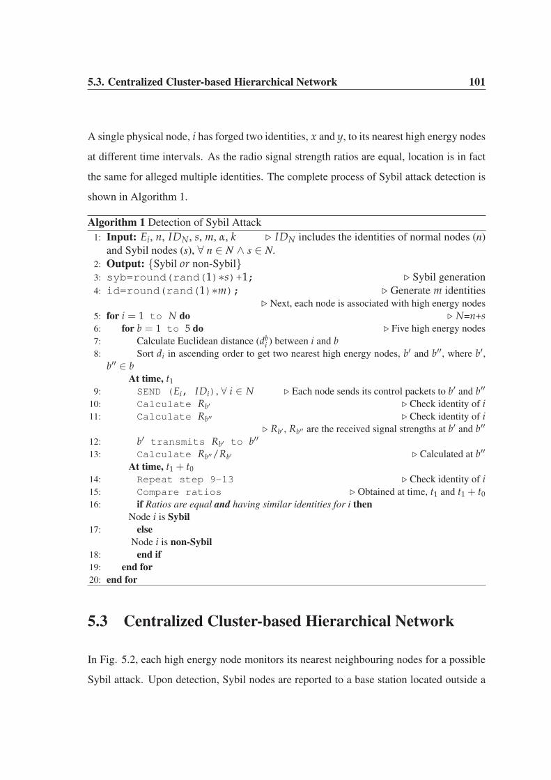
5.3. Centralized Cluster-based Hierarchical Network 101
A single physical node, i has forged two identities, x and y, to its nearest high energy nodes
at different time intervals. As the radio signal strength ratios are equal, location is in fact
the same for alleged multiple identities. The complete process of Sybil attack detection is
shown in Algorithm 1.
Algorithm 1 Detection of Sybil Attack
1: Input: Ei, n, IDN, s, m, α, k � IDN includes the identities of normal nodes (n)
and Sybil nodes (s), ∀ n ∈ N ∧ s ∈ N.
2: Output: {Sybil or non-Sybil}3: syb=round(rand(1)∗s)+1; � Sybil generation
4: id=round(rand(1)∗m); � Generate m identities� Next, each node is associated with high energy nodes
5: for i = 1 to N do � N=n+s6: for b = 1 to 5 do � Five high energy nodes
7: Calculate Euclidean distance (dbi ) between i and b
8: Sort di in ascending order to get two nearest high energy nodes, b′ and b′′, where b′,b′′ ∈ b
At time, t19: SEND (Ei, IDi), ∀ i ∈ N � Each node sends its control packets to b′ and b′′
10: Calculate Rb′ � Check identity of i11: Calculate Rb′′ � Check identity of i
� Rb′ , Rb′′ are the received signal strengths at b′ and b′′12: b′ transmits Rb′ to b′′13: Calculate Rb′′/Rb′ � Calculated at b′′
At time, t1 + t014: Repeat step 9-13 � Check identity of i15: Compare ratios � Obtained at time, t1 and t1 + t016: if Ratios are equal and having similar identities for i then
Node i is Sybil17: else
Node i is non-Sybil18: end if19: end for20: end for
5.3 Centralized Cluster-based Hierarchical Network
In Fig. 5.2, each high energy node monitors its nearest neighbouring nodes for a possible
Sybil attack. Upon detection, Sybil nodes are reported to a base station located outside a
5.3. Centralized Cluster-based Hierarchical Network 102
sensor field. Each high energy node creates a control packet containing residual energy and
identities of ordinary sensing nodes along with forged identities of detected Sybil nodes.
These packets are transmitted to a base station which makes the final decision on cluster
head selection. The base station maintains two queues, one for blacklisted Sybil nodes and
one for ordinary sensing nodes. It monitors the status of both queues at regular intervals.
The procedure of Sybil attack detection is repeated at the start of each round before cluster
formation and cluster head selection. Once a Sybil node is detected, it is blacklisted to
withhold its participation in cluster head selection. Clearly, there is a trade-off between the
cost of Sybil attack detection and energy consumption of high energy nodes. High energy
nodes remain active before the start of each round to detect new Sybil nodes. Furthermore,
they avoid communication with already blacklisted Sybil nodes to preserve their residual
energy levels.
The base station evaluates the residual energy (Ei) of ordinary sensing nodes to de-
rive an average energy threshold (Eavg). The procedure for deriving Eavg is similar to the
one discussed in Section 3.2 in Chapter 3. Any ordinary sensing node having Ei greater
than Eavg is eligible for cluster head selection. However, it is highly probable that there
will be a large number of such nodes in each round. These nodes are potential candi-
dates for cluster heads in a particular round. It is the job of base station to elect a desire
percentage of cluster heads among candidate nodes. The criteria for electing the cluster
heads among the candidates is similar to the one discussed in Section 3.2 in Chapter 3.
In our proposed scheme, the optimal percentage of cluster heads is 5% for a network of
100 nodes. An optimal percentage of such nodes is one major factor that influences the
performance of cluster-based hierarchical WSNs. A cluster head consumes more energy
in aggregating data and relaying vital information to a base station and performs general
route maintenance and some other similar tasks [148]. If a small set of cluster heads are
elected, network lifetime will degrade because these nodes will spend extra energy in data
aggregation and long-haul transmission to a base station. On the other hand, the selection
of more cluster heads will make a cluster-based network rather inefficient and ineffective.

5.3. Centralized Cluster-based Hierarchical Network 103
Unlike the centralized cluster-based hierarchical algorithm of Chapter 3, the proposed
approach for cluster formation is slightly different in this chapter. In the centralized cluster-
based hierarchical algorithm of Chapter 3, the base station was responsible for broadcast-
ing the cluster head-nomination packets to each node in order to inform them about their
nearest cluster heads. However, the proposed approach of cluster head nomination is dif-
ferent in this chapter. The base station elects an optimal percentage of cluster heads, creates
nomination packets and appends only the identities of elected cluster heads. As a result,
these packets are received only by the elected cluster heads. Upon reception of nomination
packets, each cluster head advertises itself to the nearest neighbouring nodes in order to
form clusters. Recall that Sybil nodes are blacklisted and they are not allowed to partici-
pate any further in network communication. Each non-cluster head transmits a join-request
message to a potential cluster head having the strongest signal strength in order to form
cluster. After cluster formation, each non-cluster head becomes a member node within the
cluster of its associated cluster head as shown in Fig. 5.3.
Cluster Head
100 m
100 m
Figure 5.3: Cluster formation and Data Transmission
Unlike the centralized cluster-based hierarchical routing algorithm of Chapter 3, the
cluster heads in Fig. 5.3 do not transmit their aggregated data directly to the base station.
Each cluster head collects data within its cluster in a particular round and transmits to the

5.3. Centralized Cluster-based Hierarchical Network 104
nearest high energy node which in turns transmit to the base station. The transmission of
data to a nearest high energy node reduces the energy consumption of each cluster head
as they are no longer required to use long-haul transmission links to a base station. Using
two-hop communication links not only reduces the energy consumption of each cluster
head but also enhances the quality of delivered data. Each high energy node performs data
aggregation to further improve the quality of data before delivering it to the base station.
Next, we calculate the energy consumption of various type of nodes during set-up and
steady-state phases. The energy consumption of an ordinary sensing node in a particular
cluster depends on its distance (dCH) from its respective cluster head and is computed
using Equation 5.9. Each ordinary sensing node is a member node within its cluster.
Emember =
⎧⎪⎨⎪⎩
kEelec + kε f sd2CH, dCH < dc,
kEelec + kεmpd4CH, dCH ≥ dc.
(5.9)
Once a cluster head receives data from all member nodes, it aggregates the data to
reduce its size without compromising its quality. The aggregated data is further transmitted
to a nearest high energy node for ultimate transmission to a base station. The energy
consumption of a cluster head is significantly higher than a member node and is computed
using Equation 5.10.
ECH =
⎧⎪⎪⎪⎪⎪⎨⎪⎪⎪⎪⎪⎩
kEelecn
kopt+ kEDA
nkopt
+ kε f sd2HEN , dHEN < dc,
kEelecn
kopt+ kEDA
nkopt
+ kεmpd4HEN , dHEN ≥ dc.
(5.10)
where, EDA is the energy consumption in data aggregation, k is the message size, kopt is
the optimal number of cluster heads and dHEN is the distance between a cluster head and its
nearest high energy node. Our proposed scheme is based on the idea of balanced-clustering
technique in which the number of cluster heads is equal to the number of clusters [149].

5.3. Centralized Cluster-based Hierarchical Network 105
Optimal number of cluster heads ensures that each round will have balanced clusters in
which there will be one cluster head per cluster.
The energy consumption of high energy nodes differ from each other. Before the start
of each round, ordinary sensing nodes and Sybil nodes transmit their control packets to
their two nearest high energy nodes at two different time intervals. Recall that all five
high energy nodes were involved in computationally complex task of RSSI-based Sybil
attack detection. In Fig. 5.2, hen1 calculates only the RSSI of incoming control packets.
However, the actual decision about the type (Sybil or non-Sybil) of a node is taken by
hen2. Clearly, hen2 consumes more energy because of the additional task of finding the
type of a node. Therefore, each high energy node is classified as either a received signal
strength calculator (rssc) or a Sybil detector (sd). In view of the above discussion, hen1
is an rssc while hen2 is an sd for node i. It is important to mention here that an sd node
performs dual functionality of signal strength calculation (RSSI) and Sybil detection. The
energy consumption of an rssc node is calculated using Equation 5.11.
Erssc =
⎧⎪⎪⎪⎪⎪⎪⎪⎪⎪⎪⎪⎪⎨⎪⎪⎪⎪⎪⎪⎪⎪⎪⎪⎪⎪⎩
Eelec × 2 ∑xi=1 ctri + ε f s ∑x
i=1 ctrpki d2nHEN
+kε f sd2HEN + kε f sd2
BS, dnHEN < dc,
Eelec × 2 ∑xi=1 ctri + εmp ∑x
i=1 ctrpki d4nHEN
+kεmpd4HEN + kεmpd4
BS, dnHEN ≥ dc.
(5.11)
where, ctr is a control packet sent by each node (x), dnHEN is the distance between
the rssc and its nearest sd, and dHEN is the distance between the cluster head and its
nearest high energy node. Recall that each cluster head transmits its data to the nearest
high energy node for ultimate transmission to the base station. Each node transmits two
control packets to its two nearest high energy nodes to determine its type. Furthermore,
each rssc transmits a control packet to its nearest sd which contains the received signal
strength value. The size of the control packet (ctr) is much smaller than the data packet
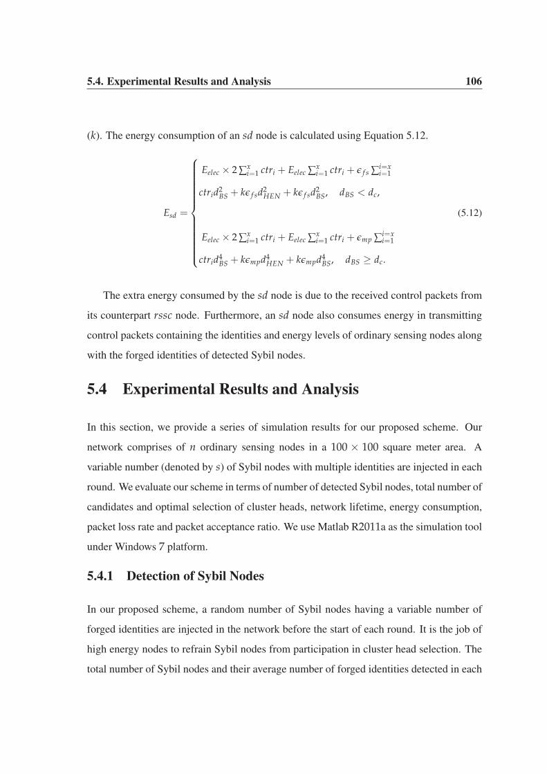
5.4. Experimental Results and Analysis 106
(k). The energy consumption of an sd node is calculated using Equation 5.12.
Esd =
⎧⎪⎪⎪⎪⎪⎪⎪⎪⎪⎪⎪⎪⎨⎪⎪⎪⎪⎪⎪⎪⎪⎪⎪⎪⎪⎩
Eelec × 2 ∑xi=1 ctri + Eelec ∑x
i=1 ctri + ε f s ∑i=xi=1
ctrid2BS + kε f sd2
HEN + kε f sd2BS, dBS < dc,
Eelec × 2 ∑xi=1 ctri + Eelec ∑x
i=1 ctri + εmp ∑i=xi=1
ctrid4BS + kεmpd4
HEN + kεmpd4BS, dBS ≥ dc.
(5.12)
The extra energy consumed by the sd node is due to the received control packets from
its counterpart rssc node. Furthermore, an sd node also consumes energy in transmitting
control packets containing the identities and energy levels of ordinary sensing nodes along
with the forged identities of detected Sybil nodes.
5.4 Experimental Results and Analysis
In this section, we provide a series of simulation results for our proposed scheme. Our
network comprises of n ordinary sensing nodes in a 100 × 100 square meter area. A
variable number (denoted by s) of Sybil nodes with multiple identities are injected in each
round. We evaluate our scheme in terms of number of detected Sybil nodes, total number of
candidates and optimal selection of cluster heads, network lifetime, energy consumption,
packet loss rate and packet acceptance ratio. We use Matlab R2011a as the simulation tool
under Windows 7 platform.
5.4.1 Detection of Sybil Nodes
In our proposed scheme, a random number of Sybil nodes having a variable number of
forged identities are injected in the network before the start of each round. It is the job of
high energy nodes to refrain Sybil nodes from participation in cluster head selection. The
total number of Sybil nodes and their average number of forged identities detected in each

5.4.2. Total Number of Candidates and Cluster Heads 107
round are shown in Fig. 5.4.
0 0.5 1 1.5 2 2.5
x 104
0
5
10
15
20
25
30
Number of rounds
Num
ber o
f Syb
il N
odes
Det
ecte
d
Number of detected Sybil NodesAverage Number of Identities per Sybil Node
Figure 5.4: Detection of Sybil Nodes and their Forged Identities
The number of Sybil nodes are as high as 20 and the average number of their forged
identities have reached upto 5 in certain rounds over the course of network lifetime. It
would have an adverse impact on the outcome of voting, data aggregation and fair resource
utilization if these nodes had gone undetected and were elected as cluster heads.
5.4.2 Total Number of Candidates and Cluster Heads
Our proposed scheme prevents Sybil nodes from participation in cluster head selection. If
the detection scheme is not in place, Sybil nodes may elect themselves as potential candi-
dates for cluster heads as shown in Fig. 5.5. The majority of Sybil nodes are capable to
nominate themselves as potential candidates for cluster heads in various rounds. However,
our detection scheme prevents their participation in cluster head selection. The perfor-
mance of base station is highly precise and accurate because it elects only 5% of cluster
heads in each round until the network has insufficient number of alive nodes toward the
end. The optimal selection of cluster heads and the prevention of Sybil nodes from partic-
ipation in cluster head selection efficiently utilize the limited energy of ordinary sensing
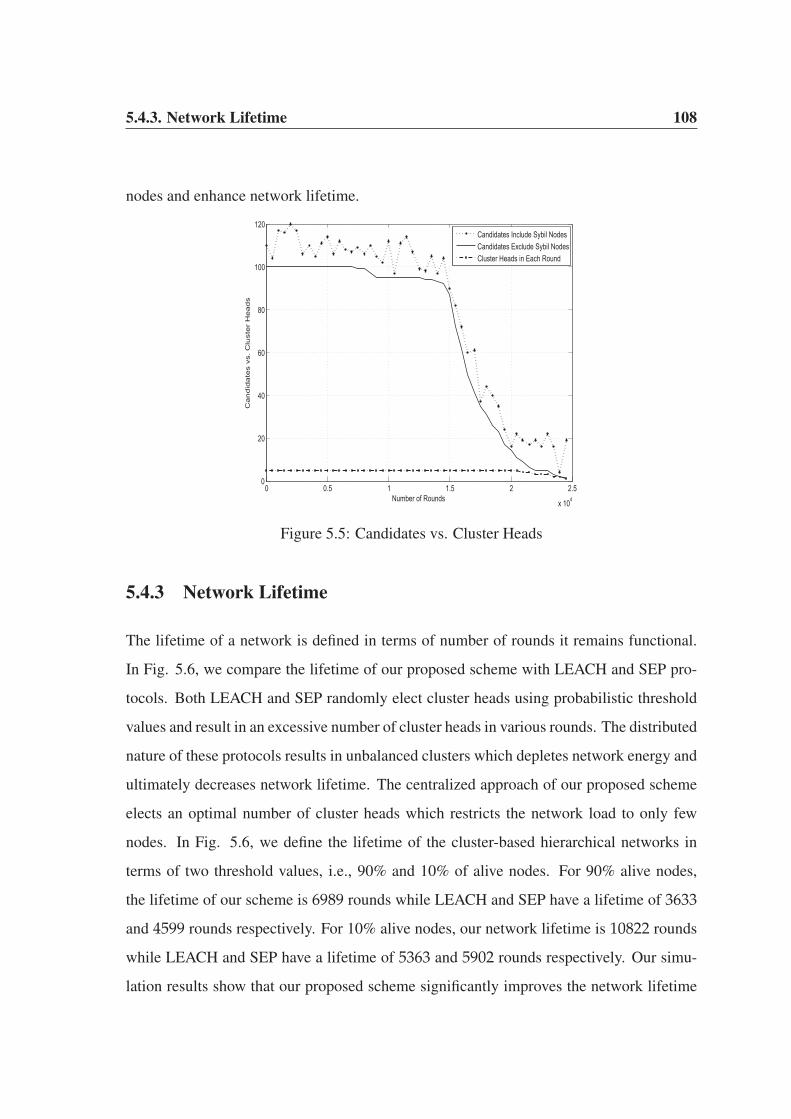
5.4.3. Network Lifetime 108
nodes and enhance network lifetime.
0 0.5 1 1.5 2 2.5
x 104
0
20
40
60
80
100
120
Number of Rounds
Candid
ate
s vs
. C
lust
er
Heads
Candidates Include Sybil NodesCandidates Exclude Sybil NodesCluster Heads in Each Round
Figure 5.5: Candidates vs. Cluster Heads
5.4.3 Network Lifetime
The lifetime of a network is defined in terms of number of rounds it remains functional.
In Fig. 5.6, we compare the lifetime of our proposed scheme with LEACH and SEP pro-
tocols. Both LEACH and SEP randomly elect cluster heads using probabilistic threshold
values and result in an excessive number of cluster heads in various rounds. The distributed
nature of these protocols results in unbalanced clusters which depletes network energy and
ultimately decreases network lifetime. The centralized approach of our proposed scheme
elects an optimal number of cluster heads which restricts the network load to only few
nodes. In Fig. 5.6, we define the lifetime of the cluster-based hierarchical networks in
terms of two threshold values, i.e., 90% and 10% of alive nodes. For 90% alive nodes,
the lifetime of our scheme is 6989 rounds while LEACH and SEP have a lifetime of 3633
and 4599 rounds respectively. For 10% alive nodes, our network lifetime is 10822 rounds
while LEACH and SEP have a lifetime of 5363 and 5902 rounds respectively. Our simu-
lation results show that our proposed scheme significantly improves the network lifetime
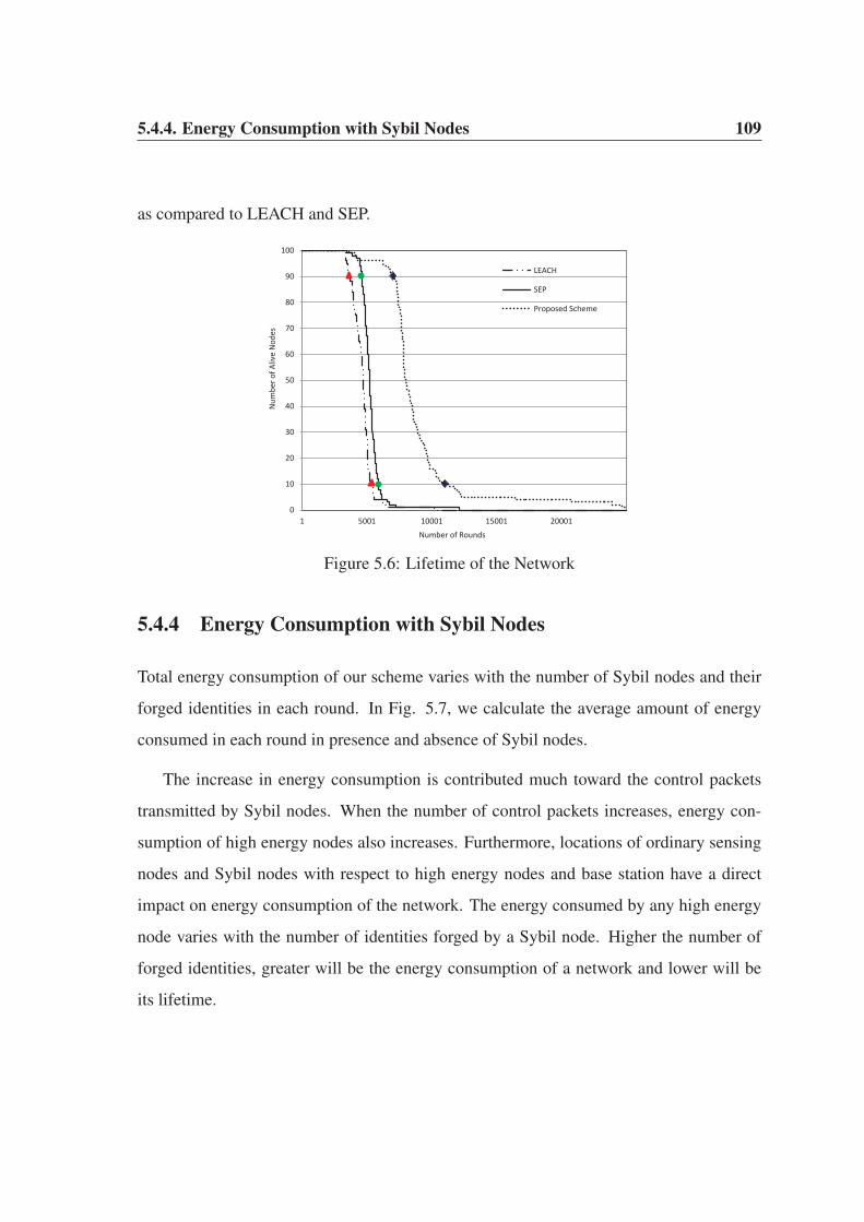
5.4.4. Energy Consumption with Sybil Nodes 109
as compared to LEACH and SEP.
0
10
20
30
40
50
60
70
80
90
100
1 5001 10001 15001 20001
Num
ber o
f Aliv
e N
odes
Number of Rounds
LEACH
SEP
Proposed Scheme
Figure 5.6: Lifetime of the Network
5.4.4 Energy Consumption with Sybil Nodes
Total energy consumption of our scheme varies with the number of Sybil nodes and their
forged identities in each round. In Fig. 5.7, we calculate the average amount of energy
consumed in each round in presence and absence of Sybil nodes.
The increase in energy consumption is contributed much toward the control packets
transmitted by Sybil nodes. When the number of control packets increases, energy con-
sumption of high energy nodes also increases. Furthermore, locations of ordinary sensing
nodes and Sybil nodes with respect to high energy nodes and base station have a direct
impact on energy consumption of the network. The energy consumed by any high energy
node varies with the number of identities forged by a Sybil node. Higher the number of
forged identities, greater will be the energy consumption of a network and lower will be
its lifetime.
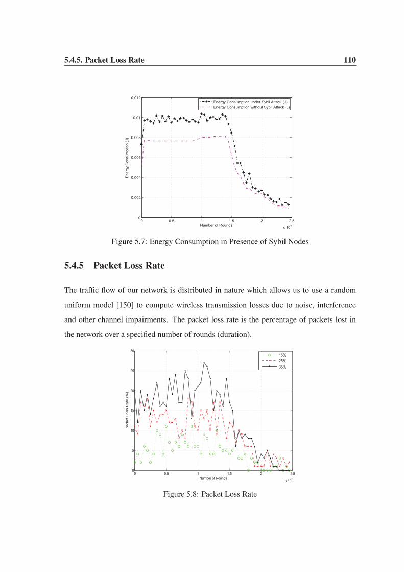
5.4.5. Packet Loss Rate 110
0 0.5 1 1.5 2 2.5
x 104
0
0.002
0.004
0.006
0.008
0.01
0.012
Number of Rounds
Ener
gy C
onsu
mpt
ion
(J)
Energy Consumption under Sybil Attack (J)Energy Consumption without Sybil Attack (J)
Figure 5.7: Energy Consumption in Presence of Sybil Nodes
5.4.5 Packet Loss Rate
The traffic flow of our network is distributed in nature which allows us to use a random
uniform model [150] to compute wireless transmission losses due to noise, interference
and other channel impairments. The packet loss rate is the percentage of packets lost in
the network over a specified number of rounds (duration).
0 0.5 1 1.5 2 2.5
x 104
0
5
10
15
20
25
30
Number of Rounds
Pack
et
Loss
Rate
(%
)
15%25%35%
Figure 5.8: Packet Loss Rate
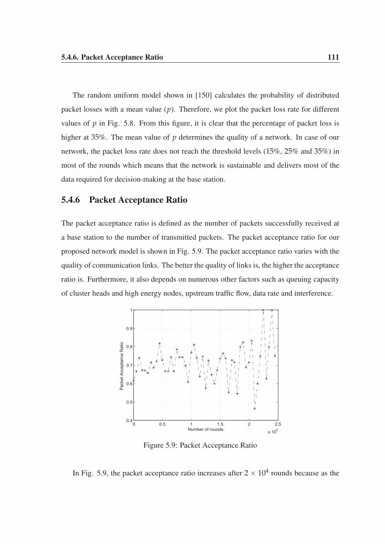
5.4.6. Packet Acceptance Ratio 111
The random uniform model shown in [150] calculates the probability of distributed
packet losses with a mean value (p). Therefore, we plot the packet loss rate for different
values of p in Fig. 5.8. From this figure, it is clear that the percentage of packet loss is
higher at 35%. The mean value of p determines the quality of a network. In case of our
network, the packet loss rate does not reach the threshold levels (15%, 25% and 35%) in
most of the rounds which means that the network is sustainable and delivers most of the
data required for decision-making at the base station.
5.4.6 Packet Acceptance Ratio
The packet acceptance ratio is defined as the number of packets successfully received at
a base station to the number of transmitted packets. The packet acceptance ratio for our
proposed network model is shown in Fig. 5.9. The packet acceptance ratio varies with the
quality of communication links. The better the quality of links is, the higher the acceptance
ratio is. Furthermore, it also depends on numerous other factors such as queuing capacity
of cluster heads and high energy nodes, upstream traffic flow, data rate and interference.
0 0.5 1 1.5 2 2.5
x 104
0.4
0.5
0.6
0.7
0.8
0.9
1
Number of rounds
Pack
et A
ccep
tanc
e R
atio
Figure 5.9: Packet Acceptance Ratio
In Fig. 5.9, the packet acceptance ratio increases after 2 × 10⁴ rounds because as the
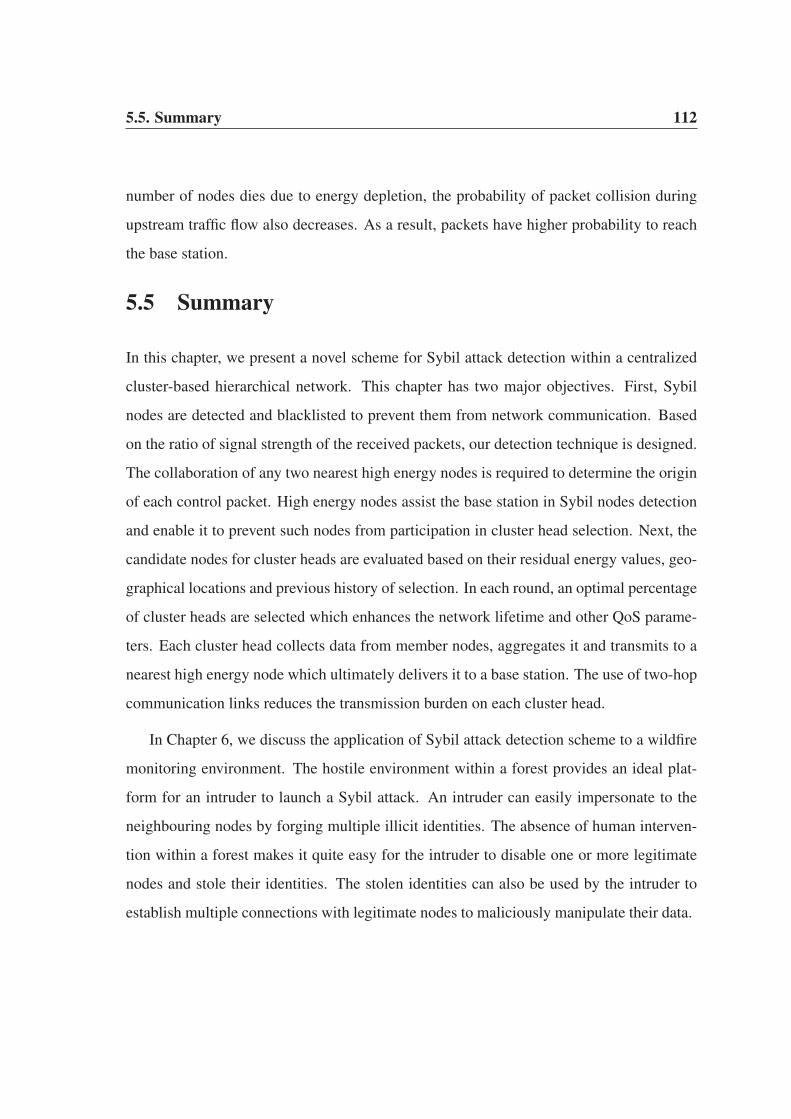
5.5. Summary 112
number of nodes dies due to energy depletion, the probability of packet collision during
upstream traffic flow also decreases. As a result, packets have higher probability to reach
the base station.
5.5 Summary
In this chapter, we present a novel scheme for Sybil attack detection within a centralized
cluster-based hierarchical network. This chapter has two major objectives. First, Sybil
nodes are detected and blacklisted to prevent them from network communication. Based
on the ratio of signal strength of the received packets, our detection technique is designed.
The collaboration of any two nearest high energy nodes is required to determine the origin
of each control packet. High energy nodes assist the base station in Sybil nodes detection
and enable it to prevent such nodes from participation in cluster head selection. Next, the
candidate nodes for cluster heads are evaluated based on their residual energy values, geo-
graphical locations and previous history of selection. In each round, an optimal percentage
of cluster heads are selected which enhances the network lifetime and other QoS parame-
ters. Each cluster head collects data from member nodes, aggregates it and transmits to a
nearest high energy node which ultimately delivers it to a base station. The use of two-hop
communication links reduces the transmission burden on each cluster head.
In Chapter 6, we discuss the application of Sybil attack detection scheme to a wildfire
monitoring environment. The hostile environment within a forest provides an ideal plat-
form for an intruder to launch a Sybil attack. An intruder can easily impersonate to the
neighbouring nodes by forging multiple illicit identities. The absence of human interven-
tion within a forest makes it quite easy for the intruder to disable one or more legitimate
nodes and stole their identities. The stolen identities can also be used by the intruder to
establish multiple connections with legitimate nodes to maliciously manipulate their data.

Chapter 6
Detection of Sybil Attack in a Wildfire
Monitoring Application
In Chapter 5, a Sybil attack detection technique for a centralized cluster-based hierarchical
network was proposed. The proposed technique assumed that the nodes have a line-of-
sight connection among them and the free-space propagation model is used for commu-
nication. Sybil nodes and their forged identities were permanently blocked in order to
prevent their participation in cluster head selection and cluster formation. In WSN, it is
probable that the identity of a sensor node may be known only to a base station but it may
not be known to other sensor nodes. The only exception is, when all the sensor nodes in a
network know the identities of each other. However, knowing the identity of each sensor
node is both resource-intensive and time-consuming. When one or more Sybil nodes are
detected by a base station, they are prevented from participation in cluster head selection.
However, any normal node in the field is unaware about the type (sybil/normal) of another
node. Each normal node assumes that all other nodes in the network are genuine, simi-
lar to it. As a result, Sybil nodes can communicate with any normal node. Sybil nodes
cannot participate in cluster head selection but they can communicate with normal nodes
during cluster formation for transmission of their data to the cluster heads. This chapter

6.1. Design Considerations 114
is based on the above concept. In this chapter, Sybil attack is detected in a forest wildfire
monitoring application. The geographical region of a forest is divided into small clusters
using a centralized cluster formation approach. Various environmental parameters such
as temperature, relative humidity and wind speed are monitored. The anomalies among
the readings of the environmental parameters determine the presence or absence of Sybil
nodes and a possible wildfire as well. First, we discuss the design considerations for a
wildfire monitoring application followed by the actual detection mechanism for a possible
Sybil attack.
6.1 Design Considerations
In this section, we provide a brief overview of various considerations which need to be in
place at the time of designing an efficient wildfire monitoring application. First, we pro-
vide a description of various environmental parameters which influence the behaviour and
characteristics of a wildfire in Section 6.1.1. Various network parameters and design con-
siderations which govern the data collection capabilities of the sensor nodes are explained
in Section 6.1.2.
6.1.1 Characteristics of Burning Wildfire Scenario
The behaviour of a wildfire is characterized by the following factors [151].
1. Fuels
2. Weather Conditions
3. Topography
These three factors determine how quickly a wildfire can spread or turn into a raging
blaze which may scorches thousands of acres of land in a short period of time. The fuels
include grass, dry leaves, twigs, shrubs and branches of the trees. Small pieces of fuels
burn quickly, particularly when they are large in quantity, dry and loosely arranged. The
weather also plays a crucial role in igniting and spreading a wildfire. On a hot and windy
6.1.2. Network Parameters and Design Consideration 115
day, fuels are at their driest which increases the risk of a wildfire. The three weather
ingredients, i.e., temperature, relative humidity and wind speed have the ability to ignite
and spread a wildfire to engulf a vast region. Temperature has a direct impact on fire
ignition because the fuels are closer to their ignition points at a very high temperature.
Each fuel has a flash point, a temperature reading at which it bursts into flames. The typical
flash point for various types of dried fuels is 300 0C1. At flash point, the fuels release
hydrocarbon gases that mixes with oxygen in the air and causes wildfire due to combustion.
Relative humidity is the percentage of moisture in the air. It has an adverse impact on
the intensity and flammability of a wildfire. During hot summer days and dry conditions,
humidity is relatively low which adds to the possibility of a wildfire as the fuels do not have
sufficient moisture in the air to absorb. The possibility of a wildfire increases when the
relative humidity drops below 30% (critical point) in the air. Wind supplies oxygen which
further dries the fuels and spreads the fire across a wide geographical region. The stronger
the wind blows, the faster a wildfire will spread. The threshold wind speed of 12-15 km/h
has a significant impact on the behaviour of a wildfire. Low relative humidity coupled
with strong winds and high temperature readings rapidly spread a wildfire. Topography
or the slope of a land also influences the behaviour of a wildfire. Topography can either
aid or hinder the progression of a wildfire because a fire spreads quickly and much faster
up a slope and slow down as it goes down a slope. Among these three factors, weather
condition is highly crucial in igniting and spreading a wildfire. It is for this reason that we
have formulated our network model based on the flash point, critical point and threshold
values of the three weather ingredients. Temperature and relative humidity ignite a wildfire
while the speed of wind facilitates in spreading it.
6.1.2 Network Parameters and Design Consideration
In WSNs, the source nodes located in close vicinity of each other capture somewhat iden-
tical data packets [152]. If such data is transmitted to a base station, it may flood the whole
1http://science.howstuffworks.com/nature/natural-disasters/wildfire.htm
6.1.2. Network Parameters and Design Consideration 116
network with multiple copies of the same data. To avoid data redundancy, an end user
specifies various conditions for data transmission. In a wildfire monitoring application,
an end user is mainly interested in threshold values of certain environmental parameters.
Threshold values enable an end user in taking swift actions according to the environmental
conditions within a forest.
In our proposed scheme, each normal node is equipped with three sensors for monitor-
ing temperature, relative humidity and wind speed. Each node remains in sleep mode and
wakes up only when the threshold conditions are satisfied by the captured data. The sleep-
awake scheduling of sensor nodes in our proposed approach enhances the network lifetime
by reducing the energy consumption. Upon capturing the events of interest, they are locally
processed and relayed back to a nearest base station. Similar to PASCCC protocol [134],
the operation of these nodes is governed by hard threshold (HT) and soft threshold (HT). A
sensor node remains idle or in sleep mode until HT is reached. For our proposed network
model, HT is set to 1000C for temperature reading, 40% for relative humidity and 8 km/h
for wind speed. These values of HT are stored locally in each node as a base value. Recall
that the temperature’s flash point is 3000C, relative humidity’s critical point is below 30%
and wind speed’s threshold is 12-15 km/h. These values are the maximum threshold read-
ings for environmental parameters at which a wildfire ignites and spread across the forest.
An end user needs to be informed well before these maximum threshold readings. It is
for this reason that we have set the values of HT for temperature, relative humidity and
wind speed to inform an end user well before any emergency situation. Each node sends
an alert packet to a nearest base station when HT is reached for these parameters. The alert
packets are constantly transmitted to keep an end user up-to-date about the current status
of a forest.
In a wildfire monitoring application, an end user is not interested in an incoming alert
packet for which the HT reading is similar to the previous one. To ensure that the incoming
alert packet has a different reading than the previous ones, we set soft threshold (ST) for
each parameter. In our proposed approach, ST is set to 400C for temperature, 2% for

6.2. Sybil Attack Detection in a Forest Wildfire 117
relative humidity and 1 km/h for wind speed. Thus, the transmitter of each sensor will
trigger for the first time when HT is 1000C for temperature, 40% for relative humidity
and 8 km/h for wind speed. In the second time, it will trigger when HT is 1400C for
temperature, 38% for relative humidity and 9 km/h for wind speed. In the third time, it
will trigger when HT is 1800C for temperature, 36% for relative humidity and 10 km/h
for wind speed. This process of adjusting the values of HT continues and alert packets are
transmitted to a nearest base station on regular intervals. The value of ST is added to the
previous HT value in order to obtain a new HT value for the current round. The threshold
values of HT and ST provide sufficient time for an end user to take precautionary measures
in an emergency situation within a forest.
6.2 Sybil Attack Detection in a Forest Wildfire
In this section, we provide a detailed explanation of our proposed scheme. First, the ar-
chitectural model of our network is presented in Section 6.2.1 followed by its deployment
model in Section 6.2.2. Next, two different approaches for Sybil attack detection are pre-
sented in Section 6.2.3. The first approach is based on the signal strength of received
packets, similar to the one presented in Chapter 5. The second approach is based on the
residual energy of each node. Both these approaches detect Sybil nodes prior to cluster
formation and cluster head selection to ensure that only legitimate nodes are elected as
cluster heads. Once Sybil nodes are barred from cluster head selection, a cluster-based
hierarchical network is formed. Section 6.2.4 presents our scheme to obtain environmental
data based on the conditions specified by an end user.
6.2.1 Network Architectural Model
The network architectural model of the proposed scheme is shown in Fig. 6.1. The Sybil
attack detection techniques and cluster-based hierarchical algorithm are supported at the
network layer. During routing, the forged identities of Sybil nodes are detected to prevent

6.2.2. Network Deployment Model 118
their participation in cluster head selection. The three environmental parameters such as,
temperature, relative humidity and wind speed are supported at the application layer.
Wireless Transmission
Low-power Lossy Links
Network Support
Application Support
Sybil Attack Detection
Clustering-based Algorithm
Transmission Layer (Transmission and Control of Data Flow)
Temperature, Humidity and Wind Speed
Figure 6.1: Network Architectural Model
The goal of Sybil nodes is to sneak into the network and provide false-negative alert
readings of the environmental parameters to an end user. Furthermore, the presence of
lossy links and a hostile environment pose a potential threat that some of these Sybil nodes
may sneak through the detection process due to varying signal strength at different time
intervals. The escaped Sybil nodes are ultimately detected by the base stations to prevent
their participation in cluster head selection. However, the escaped Sybil nodes are still
eligible to participate in the network as legitimate non-cluster head nodes. This is because
the normal nodes in the network have no idea about the identities of other normal nodes
or Sybil nodes. However, the malicious data of Sybil nodes is ultimately discarded by the
base stations to prevent its usage during critical decision-making.
6.2.2 Network Deployment Model
Our proposed network model consists of 200 normal nodes and 20 high energy nodes
deployed in a wide geographical region of (100 × 100) square meter area. The normal
nodes are equipped with 2 joules while high energy nodes are having 5 joules of residual

6.2.2. Network Deployment Model 119
energy. High energy nodes assist the base stations in Sybil attack detection and relay back
vital information. We use joint-sink mobility [153] in which two base stations are used to
avoid hotspot problems within the geographical region. Both these base stations support to-
and-fro motion to cover a subset of the nodes. Base station 1 moves horizontally between
the coordinates (25, 25) and (75, 25), while base station 2 moves horizontally between
coordinates (25, 75) and (75, 75) as shown in Fig. 6.2.
0 25 50 75 100
2
5
50
75
100
Normal Sensing Node
Sybil Node Base Station 1 Base Station 2
Base Station Mobility
Figure 6.2: Base Station Mobility
Unlike a random waypoint mobility model [135] which suits mobile nodes, we are
more interested in the sink mobility, also known as base station mobility. Our model does
not support mobile nodes as it will bring too much fluctuation in the RSSI values of the
received signals which will ultimately affect the detection process at the high energy nodes.

6.2.3. Detection of Sybil Attack 120
Both base stations provide sufficient coverage to the nodes by dividing the geographical
region equally between themselves. To-and-fro motion ensures that the source nodes no
longer require long-haul transmission to the base stations.
In a wildfire monitoring and many other delay-sensitive applications, a single base sta-
tion may not be sufficient to provide a complete network coverage in a wide geographical
region. In these applications, the source nodes generate critical events which need to be re-
ported immediately to a base station. To avoid hotspot problem [154], a single base station
may require constant movement with a predefined velocity to ensure that critical events
are not lost. In our scheme, a series of critical events are detected based on the HT and ST
values of the environmental parameters. Missing one or more events may result in a wrong
interpretation of the forest environment which may result in catastrophic circumstances.
Furthermore, precautionary measures need to be taken against external adversaries such as
Sybil nodes, which are capable to manipulate the readings of captured events.
6.2.3 Detection of Sybil Attack
Before environmental monitoring to proceed, each node needs to authenticate itself to
ensure that only legitimate nodes are elected as cluster heads. In a wildfire monitoring ap-
plication, Sybil identities may result in catastrophic circumstances by constantly providing
misleading results to an end user. If such identities are elected as cluster heads, they may
discard time-critical and decision-making data of member nodes within each cluster. In-
stead, they may either fabricate their own data or transmit data from those member nodes
which is less critical and may not be useful for an end user to take precautionary measures
within a forest. If there is a high probability of wildfire in a particular geographical region,
they may mislead an end user into believing that there is no such possibility of wildfire
in that specific region. Furthermore, they may divert its attention to those areas which are
less vulnerable to a wildfire. In view of the above discussion, we propose two different
techniques for Sybil attack detection in a forest wildfire monitoring application. Our first
approach is based on RSSI of the transmitter node while the second approach is based on

6.2.3. Detection of Sybil Attack 121
the residual energy of the nodes. The objective of both these approaches is to prevent Sybil
nodes from electing themselves as cluster heads as they may wreak havoc in the forest.
6.2.3.1 RSSI-based Sybil Attack Detection
The RSSI-based Sybil attack detection scheme within a forest is somewhat identical to the
one explained in Chapter 5. The only difference is the presence of a harsh transmission
medium within a forest. The RSSI-based detection technique of Chapter 5 was designed
for a free-space propagation model while the one proposed in this chapter is designed
for a multipath ground propagation model. Recall that the RSSI-based scheme detects
Sybil nodes based on the received signal strength at high energy nodes. In a typical forest
environment, the value of signal strength is influenced by various factors such as reflection,
refraction, physical obstacles, channel impairment, transmitter power, antenna type, and
distance between a transmitter and a receiver node. Furthermore, the strength of signal
also depends on Line-of-Sight (LoS) and Non-Line-of-Sight (NLoS) radio transmissions.
The NLoS transmission along with channel impairment causes significant reflection and
refraction of radio signals through various obstacles which results in highly fluctuating
RSSI values. As a result, the quality of a signal strength is quite poor which may enable
one or more Sybil nodes to sneak through the detection process. The fluctuating values
of the received signal strengths at time, t1, and time, t1 + t0, may result in varying RSSI
ratios. The differences in these ratios are sufficient to convince nearby high energy nodes
into believing that a transmitter is not a Sybil node. In this fashion, one or more identities
of Sybil nodes go undetected and are reported to a nearest base station as normal nodes.
High energy nodes have a fair detection policy which is equally applicable to both
normal nodes and Sybil nodes. High energy nodes have no prior knowledge if a node is
normal or Sybil. For high energy nodes, undetected Sybil nodes are also normal nodes.
Furthermore, undetected Sybil nodes try to participate in cluster head selection as well. To
prevent them from electing themselves as cluster heads, we implement a two-tier detection
process: one at high energy nodes and another one at the two base stations. The Sybil nodes

6.2.3. Detection of Sybil Attack 122
may sneak through the detection process at high energy nodes due to the fluctuating RSSI
values within a forest. However, it is highly improbable for such nodes to sneak through
the detection process at the two base stations. Unlike high energy nodes, each base station
maintains the identities of the normal nodes locally within a database. In case of Sybil
nodes, there will be a mismatch of identities and they will be barred from participation in
cluster head selection. The RSSI-based Sybil attack detection scheme within a forest is
shown in Fig. 6.3.
0 25 50 75 100
25
50
75
100
High Energy Node
2
i
1
Signal Strength Calculation
Figure 6.3: RSSI-based Sybil Attack Detection in a Forest
6.2.3.2 Residual Energy-based Sybil Attack Detection
In this section, we propose another scheme for Sybil attack detection based on the residual
energy of each node. Unlike a normal node, each Sybil node requires multiple transmis-
sions of control packets to validate its forged identities. A single Sybil node forges four
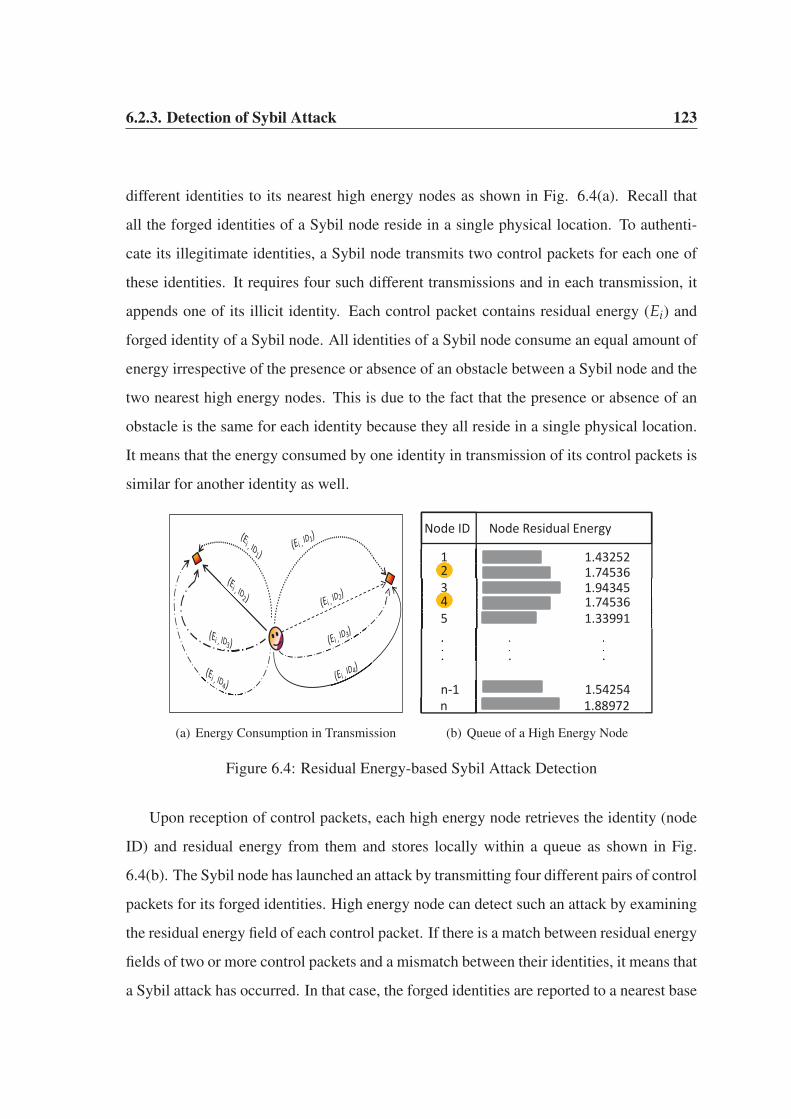
6.2.3. Detection of Sybil Attack 123
different identities to its nearest high energy nodes as shown in Fig. 6.4(a). Recall that
all the forged identities of a Sybil node reside in a single physical location. To authenti-
cate its illegitimate identities, a Sybil node transmits two control packets for each one of
these identities. It requires four such different transmissions and in each transmission, it
appends one of its illicit identity. Each control packet contains residual energy (Ei) and
forged identity of a Sybil node. All identities of a Sybil node consume an equal amount of
energy irrespective of the presence or absence of an obstacle between a Sybil node and the
two nearest high energy nodes. This is due to the fact that the presence or absence of an
obstacle is the same for each identity because they all reside in a single physical location.
It means that the energy consumed by one identity in transmission of its control packets is
similar for another identity as well.
(a) Energy Consumption in Transmission
Node ID Node Residual Energy
1 1.43252 1.74536 3 1.94345 1.74536 5 1.33991
n 1.88972 n-1 1.54254
. . . . . . . . . . . . . . .
2
4
(b) Queue of a High Energy Node
Figure 6.4: Residual Energy-based Sybil Attack Detection
Upon reception of control packets, each high energy node retrieves the identity (node
ID) and residual energy from them and stores locally within a queue as shown in Fig.
6.4(b). The Sybil node has launched an attack by transmitting four different pairs of control
packets for its forged identities. High energy node can detect such an attack by examining
the residual energy field of each control packet. If there is a match between residual energy
fields of two or more control packets and a mismatch between their identities, it means that
a Sybil attack has occurred. In that case, the forged identities are reported to a nearest base
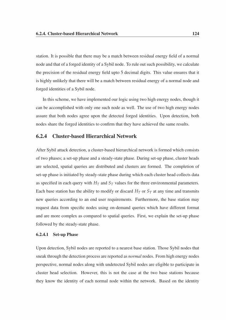
6.2.4. Cluster-based Hierarchical Network 124
station. It is possible that there may be a match between residual energy field of a normal
node and that of a forged identity of a Sybil node. To rule out such possibility, we calculate
the precision of the residual energy field upto 5 decimal digits. This value ensures that it
is highly unlikely that there will be a match between residual energy of a normal node and
forged identities of a Sybil node.
In this scheme, we have implemented our logic using two high energy nodes, though it
can be accomplished with only one such node as well. The use of two high energy nodes
assure that both nodes agree upon the detected forged identities. Upon detection, both
nodes share the forged identities to confirm that they have achieved the same results.
6.2.4 Cluster-based Hierarchical Network
After Sybil attack detection, a cluster-based hierarchical network is formed which consists
of two phases; a set-up phase and a steady-state phase. During set-up phase, cluster heads
are selected, spatial queries are distributed and clusters are formed. The completion of
set-up phase is initiated by steady-state phase during which each cluster head collects data
as specified in each query with HT and ST values for the three environmental parameters.
Each base station has the ability to modify or discard HT or ST at any time and transmits
new queries according to an end user requirements. Furthermore, the base station may
request data from specific nodes using on-demand queries which have different format
and are more complex as compared to spatial queries. First, we explain the set-up phase
followed by the steady-state phase.
6.2.4.1 Set-up Phase
Upon detection, Sybil nodes are reported to a nearest base station. Those Sybil nodes that
sneak through the detection process are reported as normal nodes. From high energy nodes
perspective, normal nodes along with undetected Sybil nodes are eligible to participate in
cluster head selection. However, this is not the case at the two base stations because
they know the identity of each normal node within the network. Based on the identity

6.2.4. Cluster-based Hierarchical Network 125
verification at the two base stations, undetected Sybil nodes are barred from participation.
Although, they are not allowed to participate in cluster head selection, undetected Sybil
nodes can still communicate with their respective cluster heads because they are considered
as normal nodes. The two base stations coordinate with each other on regular intervals to
elect an optimal percentage of cluster heads. These base stations are resource-rich entities
and are fully synchronized with each other to elect a single set of cluster heads in each
round. They elect an optimal percentage of cluster heads using a similar criteria to the one
discussed in Chapter 5.
Both base stations elect an optimal percentage of cluster heads for a particular round
and broadcasts nomination packets containing their identities and end user spatial queries.
Within each spatial query, an end user specifies certain conditions for collecting critical
events from the source nodes within a geographical region [155]. For example, a spatial
query may be “temperature readings from the nodes in a geographical region x” or “rel-
ative humidity below 35% in region y”. These are just two simple examples of spatial
queries but in reality, they can be highly complex containing various combination of these
environmental parameters. Initially, each cluster head is assigned a very simple query con-
taining HT values for temperature, relative humidity and wind speed. Each cluster head
advertises itself to the nearest neighbouring nodes in order to form clusters. Each adver-
tisement message contains the identity of a specific cluster head and the end user’s spatial
query. Upon cluster formation, each member node must abide by the conditions associated
with the advertised query. An end user may modify or discard a transmitted query at any
point of time. This is because an end user only wants the data of interest which enables it
in making critical decisions. The assignment of spatial queries is restricted to cluster heads
only. Such queries cannot be assigned to member nodes within a cluster. These queries
are useful to collect user-specific data from the nodes within a geographical region.
In a forest wildfire monitoring application, one or more member nodes may be re-
porting time-critical, delay-sensitive alert packets. An end user is more interested in the
individual readings of such nodes. Rather than waiting for a cluster head to collect such
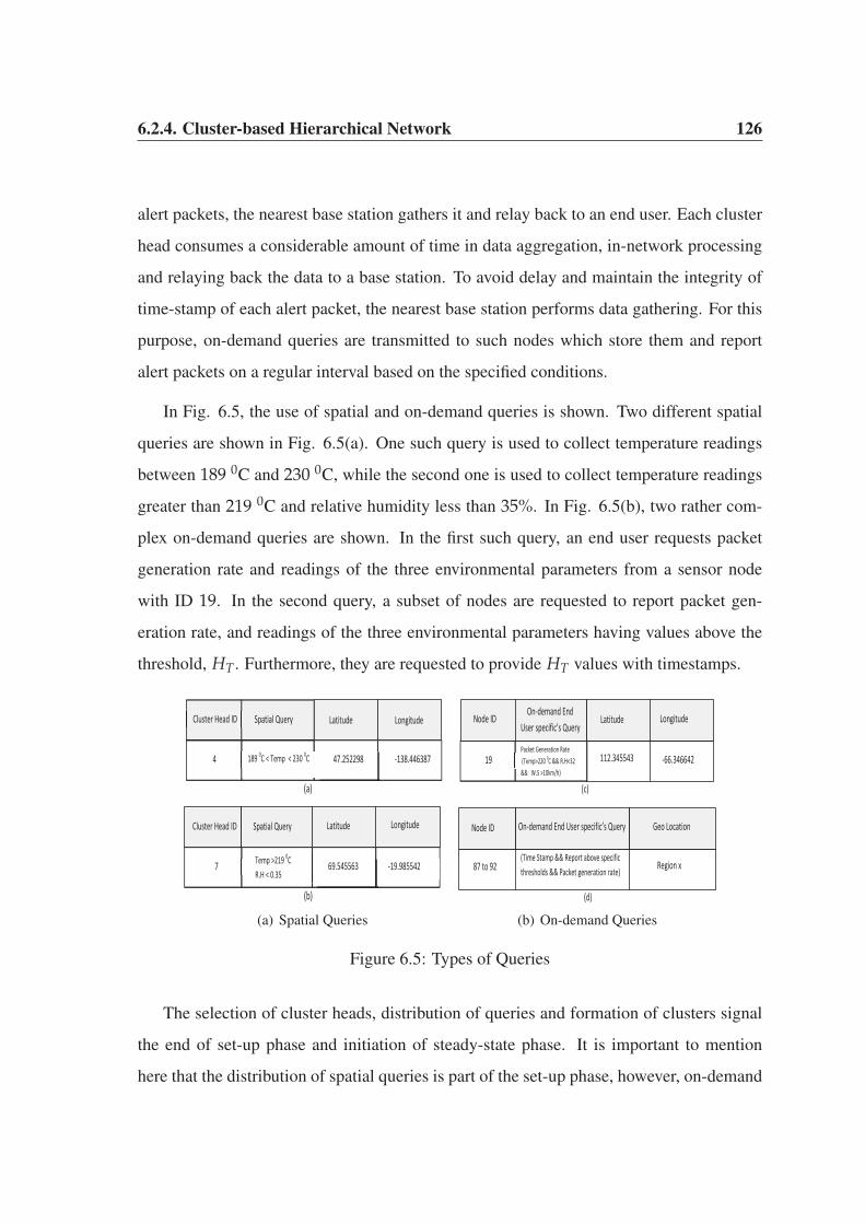
6.2.4. Cluster-based Hierarchical Network 126
alert packets, the nearest base station gathers it and relay back to an end user. Each cluster
head consumes a considerable amount of time in data aggregation, in-network processing
and relaying back the data to a base station. To avoid delay and maintain the integrity of
time-stamp of each alert packet, the nearest base station performs data gathering. For this
purpose, on-demand queries are transmitted to such nodes which store them and report
alert packets on a regular interval based on the specified conditions.
In Fig. 6.5, the use of spatial and on-demand queries is shown. Two different spatial
queries are shown in Fig. 6.5(a). One such query is used to collect temperature readings
between 189 0C and 230 0C, while the second one is used to collect temperature readings
greater than 219 0C and relative humidity less than 35%. In Fig. 6.5(b), two rather com-
plex on-demand queries are shown. In the first such query, an end user requests packet
generation rate and readings of the three environmental parameters from a sensor node
with ID 19. In the second query, a subset of nodes are requested to report packet gen-
eration rate, and readings of the three environmental parameters having values above the
threshold, HT. Furthermore, they are requested to provide HT values with timestamps.
4
Cluster Head ID
189 0C < Temp < 230 0C
47.252298
-138.446387
7 Temp >219 0C R.H < 0.35
69.545563
-19.985542
(a)
(b)
Spatial Query Latitude Longitude
Cluster Head ID Spatial Query Latitude Longitude
(a) Spatial Queries
-66.346642
87 to 92 (Time Stamp && Report above specific thresholds && Packet generation rate)
(c)
(d)
19 Packet Generation Rate (Temp>220 0C && R.H<32 && W.S >10km/h)
112.345543
Region x
On-demand End User specific’s Query
Latitude Longitude Node ID
Node ID On-demand End User specific’s Query Geo Location
(b) On-demand Queries
Figure 6.5: Types of Queries
The selection of cluster heads, distribution of queries and formation of clusters signal
the end of set-up phase and initiation of steady-state phase. It is important to mention
here that the distribution of spatial queries is part of the set-up phase, however, on-demand

6.2.4. Cluster-based Hierarchical Network 127
queries distribution may or may not be part of it. They are distributed according to an end
user requirements and importance of the reported data. Irrespective of the set-up phase or
steady-state phase, an end user may transmit on-demand queries at any point of time.
6.2.4.2 Steady-state Phase
During this phase, each cluster head allocates TDMA slots within its cluster for sharing
the transmission medium. In our proposed scheme, the member nodes within a cluster
are either normal nodes or undetected Sybil nodes. Recall that those Sybil nodes which
sneak through the detection process at high energy nodes are also eligible to participate
in data transmission within a network. These nodes may transmit quite a large amount
of false-negative alerts to an end user. Within each cluster, a cluster head collects and
aggregates data from member nodes and transmits to the nearest base station using a two-
hop transmission link. The only exception is the presence of a nearby base station. In that
case, the cluster head directly delivers data to it. Both base stations aggregate data from the
network and transmit to an end user. Based on the aggregated data, an end user decides the
next step. If a subset of neighbouring nodes is reporting sensitive alert packets on a regular
interval, the end user informs a rescue team in order to take precautionary measures within
a forest. An end user evaluates the aggregated data from each perspective before declaring
an emergency situation within a forest. The process of data collection within a forest is
shown in Fig. 6.6. Our proposed cluster-based hierarchical network is iterative in nature
which operates in rounds to collect data.
During steady-state phase, each cluster head collects data within its cluster based on
the conditions specified in a distributed spatial query. This data may be highly malicious as
the forged identities of undetected Sybil nodes may have provided a large amount of false-
negative time-critical and delay-sensitive alert packets. For a cluster head, it is impossible
to determine the nature of this data. It forwards the data to a nearby high energy node
for ultimate transmission to a base station. Upon reception at a base station, the identity,
geographical location and sensitivity of an alert packet are examined. A mismatch of
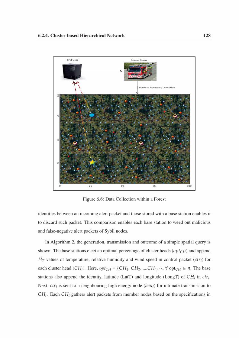
6.2.4. Cluster-based Hierarchical Network 128
0 25 50 75 100
25
50
75
100
End User Rescue Team
Perform Necessary Operation
Figure 6.6: Data Collection within a Forest
identities between an incoming alert packet and those stored with a base station enables it
to discard such packet. This comparison enables each base station to weed out malicious
and false-negative alert packets of Sybil nodes.
In Algorithm 2, the generation, transmission and outcome of a simple spatial query is
shown. The base stations elect an optimal percentage of cluster heads (optCH) and append
HT values of temperature, relative humidity and wind speed in control packet (ctri) for
each cluster head (CHi). Here, optCH = {CH1, CH2,....,CHopt}, ∀ optCH ∈ n. The base
stations also append the identity, latitude (LatT) and longitude (LongT) of CHi in ctri.
Next, ctri is sent to a neighbouring high energy node (heni) for ultimate transmission to
CHi. Each CHi gathers alert packets from member nodes based on the specifications in

6.2.4. Cluster-based Hierarchical Network 129
ctri and transmits to a nearby base station which evaluates the nature of these incoming
alert packets. If the identity of a member node (N-CHx) does not match with the identities
stored in the database (DatabaseBS) of each base station, the incoming alert packets of N-
CHx are discarded and this node is considered as a Sybil node. Each base station prevents
data from N-CHx to reach an end user. However, a match of identities would mean that
N-CHx is a legitimate node and its alert packets are further evaluated for the possibility of
assigning an on-demand query to this node.
Algorithm 2 Generation, Transmission and Outcome of Spatial Query
1: procedure SPATIAL QUERY
2: for each identity of a cluster head, CHi ∈ optCH do
3: Creates a control packet, ctri
4: Appends HT along with LatT, LongT of CHi in ctri
5: SEND ctri to heni
6: end for7: if N-CHx /∈ DatabaseBS then8: Discard the incoming alert packets from N-CHx
9: else
10: Further Evaluation of alert packets
11: end if
12: end procedure
Once data is collected from each cluster head, the two base stations further analyse this
data. The dynamic nature of happening events (wildfire in this case) is not restricted to a
particular geographical location. Moreover, the data collected from various geographical
regions may have different temperature, relative humidity and wind speed readings. Both
the base stations carefully examine the data before delivering to an end user. During this
process, the nodes which have highly sensitive data are analysed and assigned on-demand
queries. In Algorithm 3, a subset of nodes are assigned an on-demand query. This query
probes a total of 6 nodes to obtain specific values for temperature, relative humidity and
wind speed. Furthermore, each incoming alert packet must have a time-stamp otherwise

6.3. Experimental Results and Analysis 130
it will be discarded. The allocation of on-demand queries is restricted to legitimate nodes
only because the base stations have already discarded alert packets of undetected (sneaked)
Sybil nodes in Algorithm 2.
Algorithm 3 Generation and Outcome of an On-demand Query
1: procedure ON-DEMAND QUERY
2: SELECT Temp, R.H, W.S, Timestamp FROM Nodes
3: WHERE (Node ID = 2 TO 7) ∧ (Temp>= 219, R.H< 0.34, W.S> 10)
4: if Collected data is Time stamped then
5: End user checks data pattern collected from nodes in the above range
6: else
7: Discard data of the nodes without Time stamps
8: end if
9: end procedure
According to Algorithm 3, if some nodes i.e., legitimate nodes, in a particular region
are occupied by the attack, the alerts will still be transmitted by the remaining nodes to the
end user. However, if all the nodes in a particular region are occupied by the attack, alerts
will not be transmitted to the end user. When all the legitimate nodes in a particular region
are occupied by an attack, only fake alerts will be transmitted. These fake alerts will be
from the undetected Sybil nodes. However, these fake alerts are blocked from reaching the
end user by the two operating base stations. If the nodes in a particular region are powered
off, such nodes will not transmit alerts to the base station.
6.3 Experimental Results and Analysis
In this section, we provide a series of simulation results for our proposed scheme. A
(100 × 100) square meter geographical area is used for the network deployment. We use
the first-order radio model [68] to minimize the energy consumption of nodes by efficiently
scheduling their duty-cycles. We evaluate our scheme in terms of detection rate, accuracy
of the application, network lifetime and average size of the clusters. These parameters are
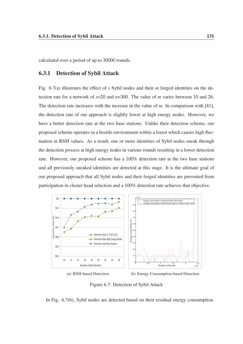
6.3.1. Detection of Sybil Attack 131
calculated over a period of up to 30000 rounds.
6.3.1 Detection of Sybil Attack
Fig. 6.7(a) illustrates the effect of s Sybil nodes and their m forged identities on the de-
tection rate for a network of s=20 and n=300. The value of m varies between 10 and 26.
The detection rate increases with the increase in the value of m. In comparison with [81],
the detection rate of our approach is slightly lower at high energy nodes. However, we
have a better detection rate at the two base stations. Unlike their detection scheme, our
proposed scheme operates in a hostile environment within a forest which causes high fluc-
tuation in RSSI values. As a result, one or more identities of Sybil nodes sneak through
the detection process at high energy nodes in various rounds resulting in a lower detection
rate. However, our proposed scheme has a 100% detection rate at the two base stations
and all previously sneaked identities are detected at this stage. It is the ultimate goal of
our proposed approach that all Sybil nodes and their forged identities are prevented from
participation in cluster head selection and a 100% detection rate achieves that objective.
98.2
98.5
98.8
99.1
99.4
99.7
100
10 12 14 16 18 20 22 24 26
De
tect
ion
Ra
te (
%)
Number of Sybil Identities
Detection Rate-K.-F.SSU et.alDetection Rate-High Energy NodesDetection rate-Base Stations
(a) RSSI-based Detection
0 0.5 1 1.5 2 2.5x 10⁴
0
0.1
0.2
0.3
0.4
0.5
0.6
0.7
0.8
0.9
1x 10⁻³
Number of Rounds
Ene
rgy
Con
sum
ptio
n (J
)
Energy Consumption of Normal Nodes (200 nodes)Energy Consumption of Sybil Nodes (upto 15 nodes in each round
(b) Energy Consumption-based Detection
Figure 6.7: Detection of Sybil Attack
In Fig. 6.7(b), Sybil nodes are detected based on their residual energy consumption.
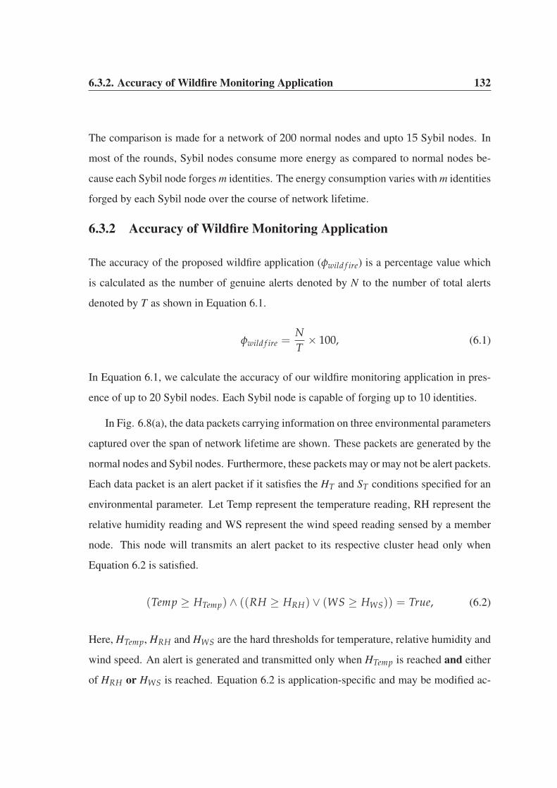
6.3.2. Accuracy of Wildfire Monitoring Application 132
The comparison is made for a network of 200 normal nodes and upto 15 Sybil nodes. In
most of the rounds, Sybil nodes consume more energy as compared to normal nodes be-
cause each Sybil node forges m identities. The energy consumption varies with m identities
forged by each Sybil node over the course of network lifetime.
6.3.2 Accuracy of Wildfire Monitoring Application
The accuracy of the proposed wildfire application (φwild f ire) is a percentage value which
is calculated as the number of genuine alerts denoted by N to the number of total alerts
denoted by T as shown in Equation 6.1.
φwild f ire =NT
× 100, (6.1)
In Equation 6.1, we calculate the accuracy of our wildfire monitoring application in pres-
ence of up to 20 Sybil nodes. Each Sybil node is capable of forging up to 10 identities.
In Fig. 6.8(a), the data packets carrying information on three environmental parameters
captured over the span of network lifetime are shown. These packets are generated by the
normal nodes and Sybil nodes. Furthermore, these packets may or may not be alert packets.
Each data packet is an alert packet if it satisfies the HT and ST conditions specified for an
environmental parameter. Let Temp represent the temperature reading, RH represent the
relative humidity reading and WS represent the wind speed reading sensed by a member
node. This node will transmits an alert packet to its respective cluster head only when
Equation 6.2 is satisfied.
(Temp ≥ HTemp) ∧ ((RH ≥ HRH) ∨ (WS ≥ HWS)) = True, (6.2)
Here, HTemp, HRH and HWS are the hard thresholds for temperature, relative humidity and
wind speed. An alert is generated and transmitted only when HTemp is reached and either
of HRH or HWS is reached. Equation 6.2 is application-specific and may be modified ac-

6.3.2. Accuracy of Wildfire Monitoring Application 133
0 0.5 1 1.5 2 2.5 3x 10⁴
0
50
100
150
200
250
300
Number of Rounds
Indi
vidu
al R
eadi
ng o
f Eac
h P
aram
eter
Temperature PacketsWind Speed PacketsRelative Humidity Packets
(a) Readings of Environmental Parameters
0 0.5 1 1.5 2 2.5 3x 10⁴
0
50
100
150
Number of Rounds
Num
ber o
f Ale
rt P
acke
ts
Genuine Alert PacketsFake Alert Packets
(b) Genuine Alerts vs. Fake Alerts
0 0.5 1 1.5 2 2.5 3x 10⁴
88
90
92
94
96
98
100
Number of Rounds
Acc
urac
y of
the
Wild
fire
Mon
itorin
g A
pplic
atio
n (%
)
(c) Percentage Accuracy
Figure 6.8: Accuracy of the Wildfire Monitoring Application
cording to the demands of an end user. This is because an on-demand query has different
conditions for an alert transmission as compared to a spatial query. As previously dis-
cussed, an on-demand query is highly generalized and assigned to a member node based
on the outcome of a spatial query. For example, an end user may require only temperature
alerts of above 200 0C from a specific geographical region and may not be interested in
relative humidity and wind speed alerts within the same region. In that case, Equation 6.2
will change accordingly. The alerts include both genuine and fake readings as shown in
Fig. 6.8(b). Fake alerts belong to the forged identities of one or more Sybil nodes while the
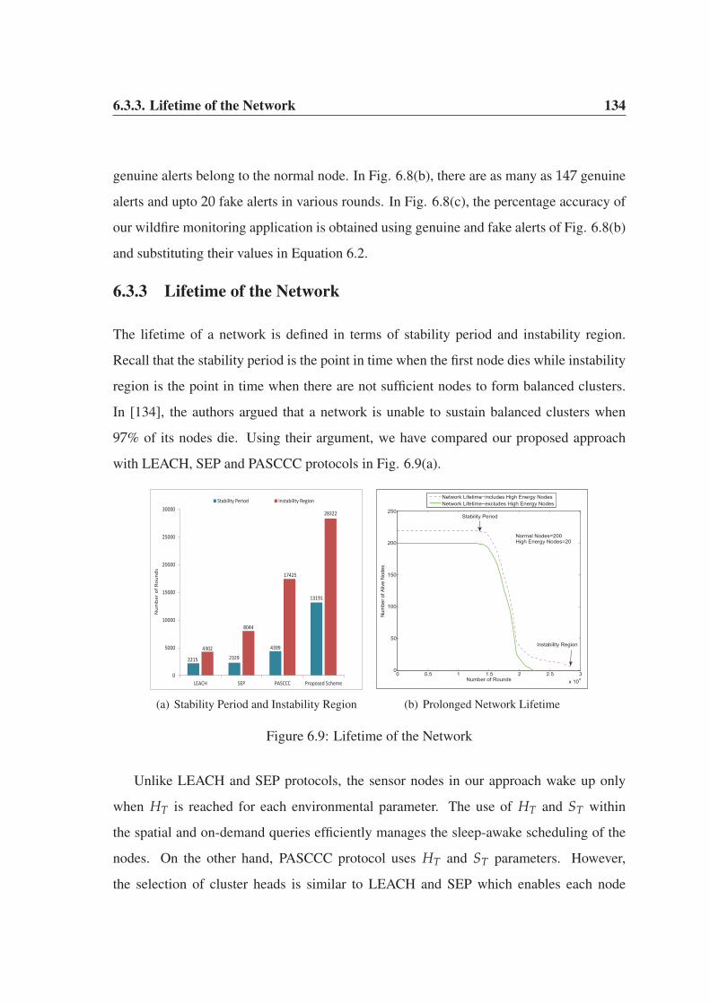
6.3.3. Lifetime of the Network 134
genuine alerts belong to the normal node. In Fig. 6.8(b), there are as many as 147 genuine
alerts and upto 20 fake alerts in various rounds. In Fig. 6.8(c), the percentage accuracy of
our wildfire monitoring application is obtained using genuine and fake alerts of Fig. 6.8(b)
and substituting their values in Equation 6.2.
6.3.3 Lifetime of the Network
The lifetime of a network is defined in terms of stability period and instability region.
Recall that the stability period is the point in time when the first node dies while instability
region is the point in time when there are not sufficient nodes to form balanced clusters.
In [134], the authors argued that a network is unable to sustain balanced clusters when
97% of its nodes die. Using their argument, we have compared our proposed approach
with LEACH, SEP and PASCCC protocols in Fig. 6.9(a).
2215 2329
4399
13191
4302
8044
17425
28322
0
5000
10000
15000
20000
25000
30000
LEACH SEP PASCCC Proposed Scheme
Num
ber
of R
ound
s
Stability Period Instability Region
(a) Stability Period and Instability Region
0 0.5 1 1.5 2 2.5 3x 10⁴
0
50
100
150
200
250
Number of Rounds
Num
ber o
f Aliv
e N
odes
Network Lifetime−includes High Energy NodesNetwork Lifetime−excludes High Energy Nodes
Normal Nodes=200High Energy Nodes=20
Stability Period
Instability Region
(b) Prolonged Network Lifetime
Figure 6.9: Lifetime of the Network
Unlike LEACH and SEP protocols, the sensor nodes in our approach wake up only
when HT is reached for each environmental parameter. The use of HT and ST within
the spatial and on-demand queries efficiently manages the sleep-awake scheduling of the
nodes. On the other hand, PASCCC protocol uses HT and ST parameters. However,
the selection of cluster heads is similar to LEACH and SEP which enables each node

6.3.4. Average Size of the Clusters 135
to elect itself as cluster head irrespective of its residual energy. The threshold-based event
detection along with a centralized cluster head selection significantly improves the stability
period and instability region of our scheme. In our proposed scheme, the instability region
reaches in round 28322 and has a 62% improvement over the nearest reading, i.e., PASCCC
protocol. In terms of stability period, our proposed scheme has almost 3 times better
performance as compared to PASCCC protocol. In Fig. 6.9(b), we calculate the network
lifetime of our proposed approach in the presence and absence of high energy nodes. The
presence of only 20 high energy nodes may have less impact on the lifetime of the network,
however, they perform vital tasks of Sybil attack detection and relaying critical data to the
base stations.
6.3.4 Average Size of the Clusters
This parameter determines the efficiency of an algorithm in terms of data aggregation and
geographical coverage [156]. The average size of a cluster (Caverage) is defined as the ratio
of number of alive nodes to the number of clusters within a network and is calculated using
Equation 6.3.
Caverage =count(nalive | Ei(nalive) > 0, ∀ nalive ∈ n)
count(CH), (6.3)
Here, nalive denotes the number of alive nodes participating in cluster formation and CH
denotes the number of clusters. In cluster-based hierarchical routing protocols, there is one
cluster head per cluster and both these parameters are always equal. The average size of
a cluster expresses the efficiency of an algorithm in terms of data aggregation, data fusion
and the minimum number of cluster heads required to cluster a large geographical network.
In Fig. 6.10(a), the average cluster size of our proposed scheme is compared with
LEACH and DEECIC protocols. Our proposed scheme has a significantly higher Caverage
as compared to DEECIC and LEACH protocols. Our algorithm is centralized in nature and
elects an optimal percentage of cluster heads in each round. On the other hand, DEECIC

6.3.4. Average Size of the Clusters 136
and LEACH are randomly distributed in nature and cannot guarantee an optimal percent-
age of cluster heads in each round. The selection of an optimal percentage of cluster heads
means a uniform distribution of network load, better coverage, high throughput, better data
aggregation and low delay within each cluster [157]. In LEACH and DEECIC protocols,
each node elects itself as cluster head based on a generated random number [61]. As a
result, either too many or very few cluster heads are elected in each round which results
in unbalanced clusters. Too many member nodes within a cluster increase the load on a
cluster head and very few member nodes make the concept of clustering rather inefficient
and ineffective. In Fig. 6.10(b), the total number of cluster heads elected in each round
are shown for a network of 100 normal nodes. Irrespective of the candidate nodes, each
round results in 4 or 5 cluster heads as long as the network is stable. As we are using a
centralized approach, the two base stations elect an optimal percentage of cluster heads
among the candidate nodes.
0
4
8
12
16
20
24
1 10 20 30
Ave
rage
Clu
ster
Siz
es
Number of Rounds
LEACH DEECIC Proposed Approach
(a) Average Cluster Size
0 0.5 1 1.5 2 2.5 3x 10⁴
0
20
40
60
80
100
120
Number of Rounds
Clu
ster
Hea
ds v
s. C
andi
date
s
Candidates includes only Normal NodesTotal Number of Cluster Heads
(b) Cluster Heads in each Round
Figure 6.10: Coverage of a Geographical Region
Fig. 6.10(a) is derived based on the statistics of Fig. 6.10(b). As discussed earlier,
Caverage is the ratio of number of alive nodes (candidates nodes of Fig. 6.10(b)) to the total
number of clusters in each round. Recall that the number of clusters is always equal to
the number of cluster heads. In Fig. 6.10(b), cluster heads vs. candidates decreases after
6.4. Summary 137
2 × 10⁴ rounds because there are not sufficient alive nodes to form balanced cluster. As a
result, the number of cluster heads in the network also decreases.
6.4 Summary
This chapter talks about the detection of Sybil attack in a wildfire monitoring applica-
tion within a forest. Two different detection techniques for Sybil attack are discussed.
The RSSI-based detection technique relies on the signal strength of control packets and is
somewhat similar to the one discussed in Chapter 5. The residual energy-based detection
technique identifies Sybil nodes based on the remaining energy of the transmitter nodes.
In both these techniques, high energy nodes play a pivotal role in the detection process.
In Chapter 5, the RSSI-based detection technique was designed for WSNs in which there
is a Line-of-Sight connection among the nodes. This technique relies on the free-space
propagation model for communication. However, the RSSI-based detection technique in
this chapter is designed for a hostile forest environment in which multipath ground prop-
agation model is a norm. The Non-Line-of-Sight connection within a forest enables one
or more Sybil nodes to sneak through the detection process deployed at the high energy
nodes. These Sybil nodes are blocked from participation in cluster head selection, how-
ever, they are still eligible to participate in the network communication. The two base
stations elect an optimal percentage of cluster heads and distribute spatial queries among
them. Each cluster head broadcasts an advertisement message to the neighbouring nodes
which contains its ID and the assigned spatial query. The neighbouring nodes are either
the undetected Sybil nodes or those normal nodes which failed to be elected as cluster
heads. In order to form clusters, both Sybil nodes and normal nodes associate themselves
with the cluster heads having the strongest signal strengths. Moreover, the member nodes
within each cluster must abide by the conditions specified within the spatial queries. These
queries contain the HT and ST values of the three environmental parameters, i.e., tempera-
ture, relative humidity and wind speed. Each cluster head collects and aggregates data from

6.4. Summary 138
member nodes and transmits to a nearest base station using a two-hop communication link.
At this point, the two base stations discard the data of Sybil nodes by comparing the iden-
tities of the source nodes with their respective databases. Once Sybil nodes are weeded
out, the two base stations carefully examines the readings (alert packets) of the three en-
vironmental parameters. Those nodes which are reporting highly critical alert packets are
assigned on-demand queries and the two base stations remain highly vigilant to ensure that
the alert packets generated due to on-demand queries are not lost. The base stations exam-
ine these alert packets and inform an end user if critical events continuously happen in any
of the geographical region. To declare an emergency situation within a forest, it is manda-
tory that the nodes (assigned with on-demand queries) are consistent in alert packets, i.e.,
they need to continuously provide highly alert packets containing the three parameters.
Chapter 7
A Lightweight Authentication Scheme
for the Internet of Things Objects
Chapters [3-6] focused mainly on energy-efficient routing techniques and Sybil attack mit-
igation strategies within the cluster-based hierarchical WSNs. The aim was to provide
network stability by avoiding the transmission of maliciously manipulated data. Recent
technological advances in the fields of RFID, wireless, cellular and sensor networks have
enabled the interaction among real-world physical objects. In this chapter, we make use
of these recent developments by embedding sensor nodes in real-world objects. This in-
tegration of sensor nodes and the physical world will empower objects to sense, process
and control occurring events and phenomena of interest. The network of physical objects,
also known as IoT, is the next wave in the era of computing outside the realm of tradi-
tional desktop [21]. The presence of embedded sensor nodes and the assignment of IP
addresses make the physical objects smart enough to interact and share data. Unlike the
Internet, the presence of physical objects in the IoT generate data on an unprecedented
scale which need to be processed, stored and presented in a seamless, efficient and simple
interpretable form. Similar to Internet, the data generated by various physical objects need
to be protected against various type of attacks. Moreover, the presence of resource-starving
7.1. Problem Statement 140
miniature sensor nodes at the core of physical objects requires extremely lightweight but
secured and robust authentication protocols.
In this chapter, we present a lightweight payload-based mutual authentication scheme
for the IoT objects. The proposed scheme uses CoAP [102] as the underlying applica-
tion layer protocol to meet the requirements of the resource-starving sensor nodes. The
lightweight features of CoAP such as low header overhead, parsing complexity, caching
and simple subscription for a resource are ideal choices in our scheme. In the IoT, the
participating objects can be easily compromised to act as potential intruders in order to
manipulate network resources. The proposed scheme authenticates the identities of clients
and the server communicating with each other. Various scenarios for the replay attack
and their mitigation are briefly explained. Our scheme can be a lightweight yet robust
and secure alternative to the DTLS protocol [158] for the IoT objects. In Section 7.1, the
problem at hand is identified which builds the foundation for our proposed scheme. In
Section 7.2, the payload-based mutual authentication scheme is discussed followed by the
detection of replay attacks and their mitigation in Section 7.3. The payload-based mutual
authentication scheme is based on our works in [119] and [159].
7.1 Problem Statement
The IoT incorporates physical objects which differ from each other in terms of various
resources and operational behaviours. The sensor nodes and actuators are embedded in
them to provide seamless and interoperable communication. These miniature sensors give
a unique ID to each participating object in the IoT paradigm. Any physical object is smart
as long as it can identify itself to the participating objects in the network. A small scale
IoT communication model consisting of various physical objects is shown in Fig. 7.1. The
client objects communicate with a NetDuino1 server for the observation of a temperature
resource. The server monitors the environmental temperature and provides its readings to
1http://netduino.com/

7.1. Problem Statement 141
the clients. Each client may specify certain conditions for the notification of temperature
readings. The electric heater, the refrigerator and the rest of the objects (clients) will not be
able to communicate with the NetDuino server in absence of an IP address. The presence
of an IP address enables an object to perform various RESTful operations in a resource-
constrained network.
Figure 7.1: A Vulnerable Internet of Things Connected Environment
The IoT objects presented in Fig. 7.1 are susceptible to a wide range of malicious
activities. An intruder may intercept the refrigerator data, manipulate it and replay in other
parts of the network. It is also possible that the attacker may inject fabricated data of its
own in the network. Therefore, a huge amount of data is at risk which may result in the
malfunctioning of the whole network. Similar to a legitimate device, a malicious object
also requires an ID to participate in a network communication. Each participating object
needs to be authenticated to establish its true identity in the network. In absence of an ID
validation and authentication scheme, an attacker will always be able to conduct a wide
range of malicious activities. An intruder may establish multiple connections with a server

7.1. Problem Statement 142
at a given time so that multiple network resources will be seized by the malicious object.
This results in the denial of services to the legitimate objects and ultimately causes scarcity
of resources in the network [34]. As wireless medium is shared among various objects, the
intruder may block access to the network resources by continuously emitting jamming
signals to interfere with legitimate transmissions [109]. The presence of wireless medium
can easily expose objects to eavesdropping as well.
To detect and mitigate various types of attacks in a network, extremely lightweight
but secure protocols need to be designed in view of the limited resources of sensor nodes.
In today’s Internet, considerable efforts have been spent on securing the existing standard
authentication and authorization protocols such as TLS [111], Anonymous Authentication
Protocol (AAP) [160] and Kerberos [161] among others. It indeed saves a lot of efforts if
these protocols are customized to be feasible for resource-constrained networks. However,
these protocols were not designed with the constrained resources in mind, which is one of
the most important limitations with WSN. Therefore, profiling of an existing authentication
protocol may not result in an optimal solution. Another major concern is that the existing
authentication protocols may not necessarily comply with their original design objectives
if they are used outside their intended domains of applications [162]. Almost all of the au-
thentication and encryption schemes in constrained networks are based on DTLS protocol.
However, DTLS includes computationally complex and resource consuming cipher-suites
and hence provides an expensive secure solution to these networks. Most of the DTLS-
based encryption schemes emphasize on the use of DTLS without stateless cookies. With
the absence of stateless cookies, however, a server will be exposed to replay attacks [163].
In view of the above discussion, our objective is to develop a lightweight CoAP-
based authentication scheme for the objects in an IoT paradigm. An important ques-
tion which arises is “How lightweight does a protocol need to be?” A protocol is suffi-
ciently lightweight if there are ample resources available to other tasks after its deploy-
ment. Therefore, the aim of our proposed approach is to develop an authentication scheme
which meets the above requirements. We have developed an authentication algorithm us-

7.2. Payload-based Mutual Authentication 143
ing the basic principles of the CoAP for RESTful interactions. It is a lightweight mutual
authentication scheme for any client wishing to interact with a server to establish a secure
communication channel. Upon mutual authentication, the clients communicate with the
server for the resource observation. Only the authenticated clients are allowed to observe
the resources.
7.2 Payload-based Mutual Authentication
CoAP and our authentication scheme are not two separate protocols. For the authenti-
cation, we have added security features into CoAP to make it more robust, efficient and
secure against various malicious activities. Like any communication network, preserving
resources in an IoT domain is of utmost importance. Both the client and the server have
equal chances to be compromised in the network. Therefore, it is important to authenticate
the identities and integrity of the communicating parties in order to prevent the transmis-
sion of malicious data within the network.
In our scheme, the clients and the server challenge each other for the authentication
process. Four handshake messages are used to complete the authentication and in each
message the payload does not exceed 256 bits. We use the payload of each message to
secure the integrity of clients and the server. Encryption and decryption techniques are
applied to the payload at the sender and receiver end in order to authenticate each other.
The Advanced Encryption Standard 128-bit (AES-128) algorithm is used for payload en-
cryption. We believe that the 128-bit encryption is sufficient for most of the resource-
constrained objects in an IoT paradigm. Highly secured authentication schemes such as,
AES-192 and AES-256 involve excessive computational and time-consuming tasks which
require sophisticated hardware and software platforms. However, the majority of resource-
constrained objects of an IoT environment do not have such provisioning of sophisticated
hardware and software platforms. The proposed authentication scheme is completed using
the following four phases.

7.2. Payload-based Mutual Authentication 144
1. Session/Connection initiation
2. Server challenge
3. Client response and challenge
4. Server response
The session initiation is preceded by the provisioning phase. It is a prerequisite offline
phase during which the clients share a 128-bit pre-shared secret (λi) with the server. Each
pre-shared secret is known only to the server and the client to whom it belongs. The server
maintains a table of such secrets, each one belonging to a particular client as shown in
Table. 7.1. Each client has a unique ID which enables the server to perform a table look-
up for the identity verification of the object. Upon successful verification, both parties
communicate with each other for exchanging the session key. It is assumed that the end-
devices are tamper-safe to avoid compromising the security primitives in accordance with
the Internet Threat Model [164].
Table 7.1: Pre-Shared Secrets Table
Object ID (i) 1 2 3 4 5 6 ..... n
Pre-Shared Secret (λi) λ1 λ2 λ3 λ4 λ5 λ6 ..... λn
• In the session initiation phase, each client sends a request message to the server
similar to a Hello Client message as shown in Fig. 7.2. It is a confirmable request
for the creation of a session as a resource at the server. The request is sent to the
server’s URI, /.well-known/authorize. Each message has a specific token for cor-
relating the request with a matching response. The object ID is transmitted in the
message payload. Two options, Auth and Auth-Msg-Type, are included in the re-
quest whose values indicate the type of operation performed on a resource at the
server. Upon successful verification of the client ID, the resource authorize will be
created at the server. The combination of Auth=true and Auth-Msg-Type=0 indicates
a session initiation request to the server.

7.2. Payload-based Mutual Authentication 145
Figure 7.2: Four-way Authentication Handshake
• During the server challenge phase, the server retrieves the object ID from the payload
of a session initiation request. Using this ID, the server performs a table look-up for
a matching λi. If a match is found, the server responds back with an encrypted
payload using the AES algorithm. As a new session is created for the client, a
response code of 2.01 (Created) is included in the message. If the server is unable
to find a matching λi, it will send a 4.01 (Unauthorized) response code. Moreover,
the server needs to include the same message ID and the token which were present
in the session initiation request. It can do so by simply copying them into the server
challenge response. This enables the client to correlate a confirmable request with
7.2. Payload-based Mutual Authentication 146
the corresponding response message. To create the challenge, the server generates a
pseudorandom nounce (ηserver) and a potential session key (μkey) of 128 bits each.
Nonce is a temporary number used only once by an object in the entire cryptographic
communication. At this stage, an encrypted payload is generated. First, an Exclusive
OR operation is performed on λi and μkey using Equation 7.1.
ψresultant = λi ⊕ μkey. (7.1)
Next, the 128-bit resultant (ψresultant) is appended to ηserver and encrypted with λi
to generate an encrypted payload of 256-bit using Equation 7.2. This encrypted
payload is transmitted to the client as a challenge.
γserver-payload = AES{λi, (ψresultant|ηserver)}. (7.2)
• In the client response and challenge phase, the client needs to decipher γserver-payload
to retrieve the potential session key (μkey). If the client is successful to do so, it will
have the correct ηserver and μkey. The ηserver and the μkey are known only to the
server while λi belongs to a specific client. Only a legitimate client can decipher
this challenge. An intruder can only eavesdrop on the ηserver and the μkey, but not
on the λi in accordance with the Internet Threat model [164]. The client uses its λi
to decipher the payload. Upon successful deciphering, the client has authenticated
itself. As mutual authentication requires both parties to be verified, the server also
needs to authenticate itself [165]. The client generates a new encrypted payload
similar to the server. First, an Exclusive OR is performed on ηserver and λi using
Equation 7.3.
ψresultant = ηserver ⊕ λi. (7.3)
Next, the 128-bit ψresultant is appended with ηclient and encrypted with μkey as shown
in Equation 7.4. The client-encrypted payload (γclient-payload) is transmitted to the

7.2. Payload-based Mutual Authentication 147
server as a challenge.
γclient-payload = AES{μkey, (ψresultant|ηclient)}. (7.4)
• Finally, in the server response phase, the server deciphers γclient-payload of the client
challenge to observe the ηserver in it. If present, the server realizes that the client
has successfully authenticated itself. The server retrieves the ηclient and creates an
encrypted payload of its own by appending the ηclient to μkey and encrypting with
λi as shown in Equation 7.5. Next, the 256-bit encrypted payload (γserver-payload) is
transmitted in response to the client challenge.
γserver-payload = AES{λi, (ηclient|μkey)}. (7.5)
At this point of time, the status of the resource changes to Authenticated at the
server as both parties are mutually authenticated. However, the client has yet to ver-
ify the authenticity of the server, so it decrypts the γserver-payload and observe ηclient
in it. As the client is the one which generated the ηclient, the client comprehends
that the response is from a legitimate server. At this stage, both the client and the
server have agreed upon a common session key (μkey) for the mutual authentication
and are authorized to use the key for exchanging the data packets (βdata) as shown
in Equation 7.6.
κclient-server = AES{μkey, βdata}. (7.6)
Each client and a server uses μkey for encrypting/decrypting βdata. The value of μkey varies
from one client to another because each one has a different λi. The complete pseudo-code
for the payload-based four-way handshaking authentication is shown in Algorithm 4. For
guaranteed responses from the server, CON messages are used by clients in the transmitted
requests. The responses from the server are also provided in CON messages. The use of
various response codes such as 2.01, 2.04 and 4.01 were discussed in Chapter 2.

7.2. Payload-based Mutual Authentication 148
Algorithm 4 Lightweight Payload-based Mutual Authentication
Input: Ci : Client ID, λi : {0, 1}128, where i = 1, 2, . . . , n� λi is 128-bit
Output: {Access Granted or Access Denied}Initialization:
(a) Each Client i is provided with a unique Ci and λi
(b) A server S is provided with all Ci and λi
Four-way Handshaking Proceeds:
1. Session Initiation: The Client i sends a CON message of payload Ci to S2. Server Challenge: S retrieves Ci to find a matching λi
if Ci matches λi thenSession Created 2.01Next, S responds with an encrypted payload, AES {λi, (λi ⊕ μkey|ηserver)}, where
μkey, ηserver = {0, 1}128 and message size={0, 1}256
elseCi Unauthorized 4.01end if3. Client Response & Challenge: The Client i deciphers challenge and responds with
an encrypted payload, AES {μkey, (ηserver ⊕ λi|ηclient)}, where ηclient = {0, 1}128,
message size={0, 1}256
4. Server Response: S checks the ηserver in the client challenge by comparing against
the ηserver generated in the server challenge
if Both matches thenAccess Granted- Ci Authenticated 2.04
� As client is authorized, so the resource at the server changes from session
creation 2.01 to successful authentication 2.04.
S responds as AES {λi, (ηclient|μkey)} , messagesize = {0, 1}256
elseAccess Denied-Ci Unauthenticated 4.01 � Unsuccessful Authorization
end ifData Transmission: Mutual data exchange between S and Ci using AES
{μkey, (βdata)}, where βdata = {0, 1}n, n is the varying payload size in bytes
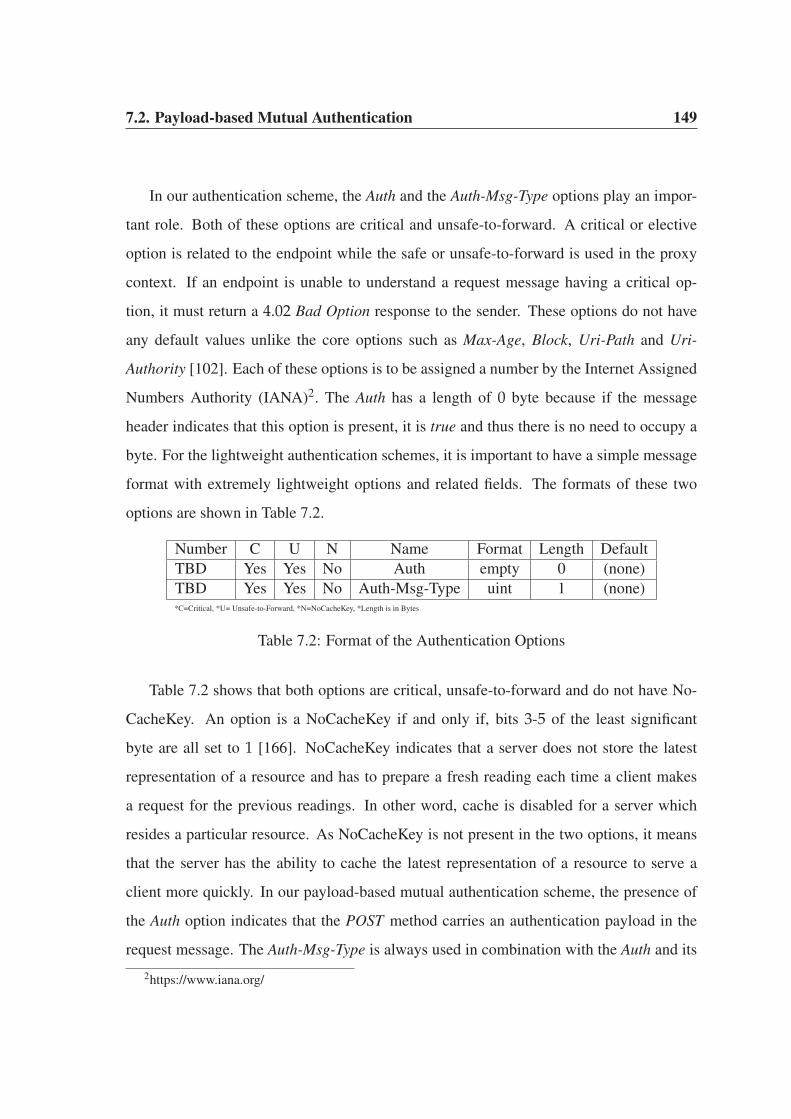
7.2. Payload-based Mutual Authentication 149
In our authentication scheme, the Auth and the Auth-Msg-Type options play an impor-
tant role. Both of these options are critical and unsafe-to-forward. A critical or elective
option is related to the endpoint while the safe or unsafe-to-forward is used in the proxy
context. If an endpoint is unable to understand a request message having a critical op-
tion, it must return a 4.02 Bad Option response to the sender. These options do not have
any default values unlike the core options such as Max-Age, Block, Uri-Path and Uri-
Authority [102]. Each of these options is to be assigned a number by the Internet Assigned
Numbers Authority (IANA)2. The Auth has a length of 0 byte because if the message
header indicates that this option is present, it is true and thus there is no need to occupy a
byte. For the lightweight authentication schemes, it is important to have a simple message
format with extremely lightweight options and related fields. The formats of these two
options are shown in Table 7.2.
Number C U N Name Format Length Default
TBD Yes Yes No Auth empty 0 (none)
TBD Yes Yes No Auth-Msg-Type uint 1 (none)*C=Critical, *U= Unsafe-to-Forward, *N=NoCacheKey, *Length is in Bytes
Table 7.2: Format of the Authentication Options
Table 7.2 shows that both options are critical, unsafe-to-forward and do not have No-
CacheKey. An option is a NoCacheKey if and only if, bits 3-5 of the least significant
byte are all set to 1 [166]. NoCacheKey indicates that a server does not store the latest
representation of a resource and has to prepare a fresh reading each time a client makes
a request for the previous readings. In other word, cache is disabled for a server which
resides a particular resource. As NoCacheKey is not present in the two options, it means
that the server has the ability to cache the latest representation of a resource to serve a
client more quickly. In our payload-based mutual authentication scheme, the presence of
the Auth option indicates that the POST method carries an authentication payload in the
request message. The Auth-Msg-Type is always used in combination with the Auth and its
2https://www.iana.org/

7.3. Detection of Replay Attacks and their Mitigation 150
value indicates the type of authentication request by the client. If its value is 0, it indicates
a session initiation request and if its value is 1, it indicates a client response and challenge.
7.3 Detection of Replay Attacks and their Mitigation
In Section 7.1, we have identified various possibilities for a replay attack in a typical IoT
environment. In this section, we provide a list of solutions to combat them. The identity
validation approach of our authentication scheme can eliminate most of such attacks at the
first instance. However, the intruder always tries to gain access to a network by different
means. If an intruder manages to infiltrate in a communication network, it can capture data
packets and replay them to the clients as shown in Fig. 7.3. An intruder A eavesdrops on a
full-duplex wireless link between the server S and a client C1. It captures the data packets
and replay them to C1, C2 and C4 along the way.
Figure 7.3: The Replay Attack in an IoT Environment

7.3. Detection of Replay Attacks and their Mitigation 151
In our proposed scheme, the clients register themselves with a server upon successful
authentication for resource observation. The registration request message (RRM) has an
observe option, which has a 24-bit sequentially incremental sequence number. When the
server realizes the presence of an observe option in an RRM, it registers the client and
notifies it upon each state change of a resource. The client has the option to specify certain
conditions for notification updates. Each client stores the RRM in its queue which has
a unique token and a message ID for correlating the response notifications. Each of the
incoming notifications from the server will have an incremental sequence number, a token
and a message ID similar to an RRM. Potentially, a single RRM can generate an enormous
amount of notification updates. In Fig. 7.3, the clients may not be interested in each noti-
fication update and may be more interested in those updates when the state of a resource
changes and the criteria specified for the notification updates are fulfilled. This reduces
the number of notification updates and at the same time minimizes the computational cost
and energy consumption of a client. In each notification response, the server appends an
observe option to enable the clients for keeping track of incoming notifications.
To detect a replay attack, each client compares the message ID and token of an incom-
ing notification against the similar parameters of an RRM. If these parameters match, the
client checks the sequence number of the incoming notification. To do so, the client can
make use of a simple logic by comparing the incoming notification with the previously
received notification from a server as shown in Equation 7.7.
Ω f reshness = f resh when[(Vi < Vj) ∧ (Vj − Vi < 223)]∨[(Vi > Vj) ∧ (Vi − Vj > 223)], (7.7)
Here, we have used the freshness of the notification responses (Ω f reshness) from a server
as a measure to detect a replay attack. In this equation, Vj and Vi are the 24-bit sequence
numbers of an observe option in an incoming (latest) notification and a previously received
notification. A notification is fresh and latest if Vj is greater than Vi and their difference is
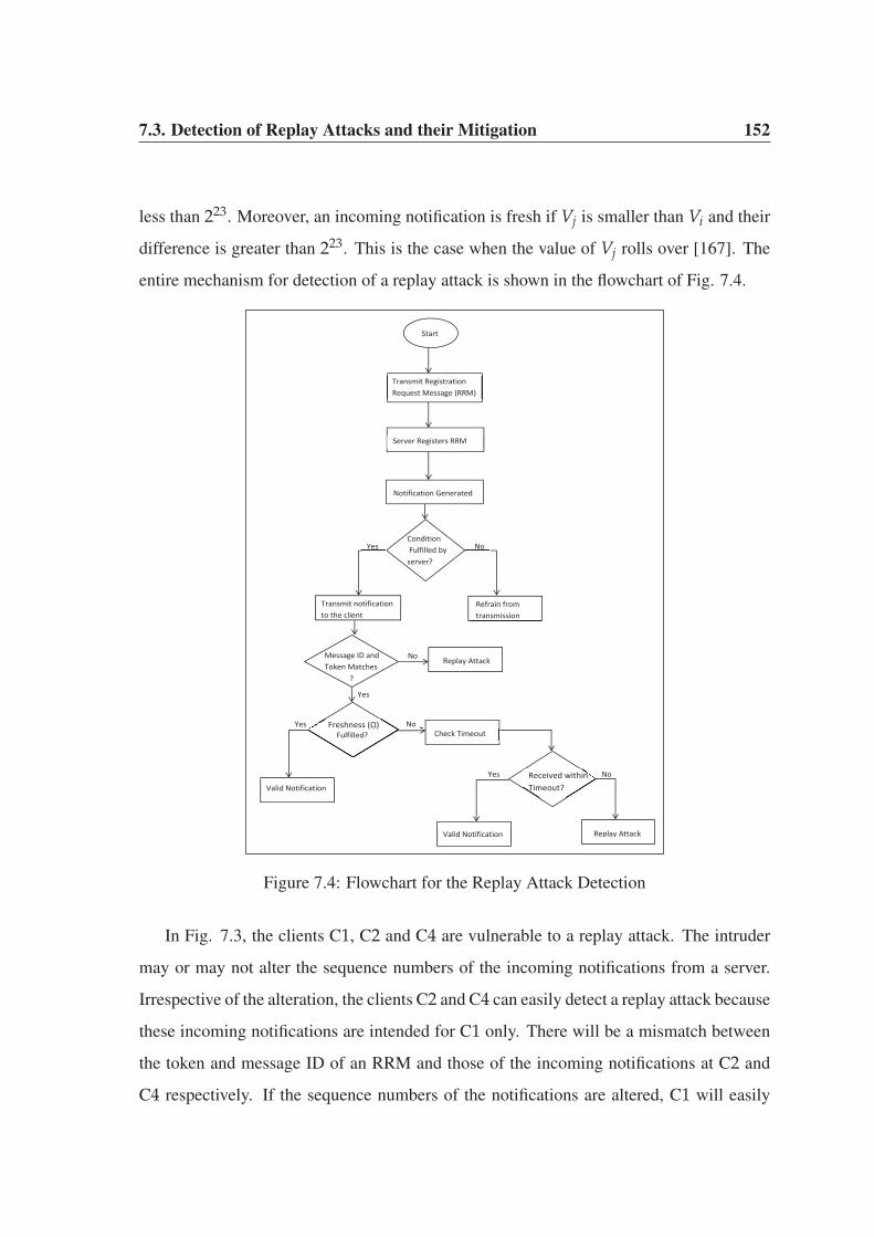
7.3. Detection of Replay Attacks and their Mitigation 152
less than 223. Moreover, an incoming notification is fresh if Vj is smaller than Vi and their
difference is greater than 223. This is the case when the value of Vj rolls over [167]. The
entire mechanism for detection of a replay attack is shown in the flowchart of Fig. 7.4.
Start
Transmit Registration Request Message (RRM)
Server Registers RRM
Condition Fulfilled by server?
Yes No
Transmit notification to the client
Refrain from transmission
Message ID and Token Matches ?
Freshness (ῼ) Fulfilled?
Yes
Valid Notification
Yes
No Replay Attack
No Check Timeout
Received within Timeout?
Yes
Valid Notification Replay Attack
No
Yes
Notification Generated
Figure 7.4: Flowchart for the Replay Attack Detection
In Fig. 7.3, the clients C1, C2 and C4 are vulnerable to a replay attack. The intruder
may or may not alter the sequence numbers of the incoming notifications from a server.
Irrespective of the alteration, the clients C2 and C4 can easily detect a replay attack because
these incoming notifications are intended for C1 only. There will be a mismatch between
the token and message ID of an RRM and those of the incoming notifications at C2 and
C4 respectively. If the sequence numbers of the notifications are altered, C1 will easily

7.3. Detection of Replay Attacks and their Mitigation 153
detect it by comparing the notifications with the previous one. However, if the intruder
replays the notifications without any modification, it becomes a tricky situation as C1 is
indeed waiting for such notifications from the server. There will be a match of the tokens
and message IDs between an RRM and incoming notifications. Moreover, the sequence
numbers are also in the same order as expected by this client.
To solve this puzzle, the clients can use a time stamp field in a registration request
and a notification response [168]. Alternatively, each client may store in a queue the
notifications previously received from a server within an acknowledgement timeout (Ack
timeout). As the incoming notifications to a client C1 are replayed by an intruder, their
timeout values play a crucial role. At this point of time, the client does not know whether
the incoming notifications are replayed or not. Therefore, it checks the sequence number
of these notifications against the previously received notifications in a sequential order.
For example, the incoming notification (Vn) is checked against Vn−1 to determine if it was
received within an Ack timeout after the successful reception of Vn−1.
The above scenarios are linked to an intruder which somehow manages to sneak through
the authentication phase and performs replay and other malicious activities during the
communication phase. In our authentication scheme, ηserver and ηclient are generated by a
pseudorandom number (Ri) which is appended to a timer (Ti). This combination of Ri and
Ti assures that an intruder will find it even more difficult to replay messages. Here, Ti is
to guarantee that ηserver and ηclient are non-reproducible. At the same time, Ti is to ensure
that ηserver and ηclient are non-predictable.
As our scheme is specifically designed for Lower-power and Lossy Networks (LLNs),
the intruder can easily eavesdrop on the communication in transit. In doing so, it can
even capture a server challenge payload and retrieve ηserver and μkey from it. Using these
parameters, it can generate an encrypted payload and transmit to the server. However, an
intruder requires λi for encrypting the payload. The lack of an authentic λi will generate a
suspicious payload for a server to decrypt and will be immediately ignored by it.
7.4. Experimental Results and Analysis 154
7.4 Experimental Results and Analysis
In this section, we provide the experimental results for our proposed scheme. We have
used the NetDuino Plus 2 boards for the client and server interaction model. First, we
perform our experimental works on the build-in emulator provided within the .NET Micro
Framework for the Netduino Plus 2 boards. Next, we implement the code on the boards
for the real-world environment of Fig. 7.1. The NetDuino server uses a DS18B20 tem-
perature sensor to obtain the temperature readings. Upon successful authentication, the
clients are allowed to observe the temperature resource. We use the CoAPSharp3 library
which provides a very basic communication model for resource exchanges. For the au-
thentication provisioning, we have created our own library, CoAPMicro which runs on top
of the CoAPSharp and uses its basic communication model. The library is efficient and
robust, and consumes relatively less amount of resources. To justify our claim, a detailed
comparison against various existing schemes is presented here.
7.4.1 Authentication
Each client needs to authenticate itself for observation of the resources. In Fig. 7.5(a), the
successful handshake between a client and the server is shown. The Auth and the Auth-
Msg-Type are the extended options used only for our authentication purpose. They are
yet to be assigned numbers by IANA, so they appear as unrecognized. We use temporary
numbers 0x101(257) and 0x102(258) for these options in our library using the option
registry mechanism. The client and the server have successfully agreed upon a common
session key and the handshake duration along with the round-trip response time is obtained.
In Fig. 7.5(b), the client is unable to decipher the server challenge as it does not possess
the required secret (λi). The outcome is an incorrect session key which causes the denial
of access to the resource. In both cases, the presence or absence of the secret determines
the outcome of the authentication.
3http://www.coapsharp.com/

7.4.2. Handshake Duration 155
Exchange routine started on thread 0x03. -SERVER- Key: 4F9DB1949D924031-8C77BE06276ECB25 Nonce1: 26C1B93F46C133A7-376D867B0F990023 Nonce2: Exchange routine started on thread 0x04. #1 [0xCA337F4A6DDBB66C] ACK 4.01 (Unauthorized) -CLIENT- Sending AUTH greeting message to server. [WARNING] Unrecognized option 0x101. Defaulted to opaque format. [WARNING] Unrecognized option 0x102. Defaulted to opaque format. -CLIENT- Server challenge: #2 [0x44A2B63A183163C6] ACK 2.01 (Created), 1196 ms -CLIENT- Key: 5CDA810C12EE36AE-16C3D4FA0EA79FDF Nonce1: 26C1B93F46C133A7-376D867B0F990023 Nonce2: 7562DB9C6D7DED45-5D767BD30B3EA320 -CLIENT- Replying to server challenge... -CLIENT- Final reply from server: #3 [0xF845FAFB4C983061] ACK 2.04 (Changed), 96 ms -CLIENT- Total handshake duration: 2559 ms -CLIENT- Mutual trust acquired. Authentication handshake completed. -CLIENT- Server is TRUSTED.
(a) Resource Access Granted
The thread '<No Name>' (0x2) has exited with code 0 (0x0). [CLIENT] Started. The thread '<No Name>' (0x2) has exited with code 0 (0x0). [SERVER] Started. [SERVER] Key: 4F9DB1949D924031-8C77BE06276ECB25 Nonce1: 4BAFCDE9430E5773-24E5095A6614BF17 Nonce2: [CLIENT] Key: 6619DB083FA7049A-70F225566ED3847A Nonce1: 4BAFCDE9430E5773-24E5095A6614BF17 Nonce2: 6DFB243F1F64BE50-142C6CFE3382DAAF [CLIENT] Replying to server challenge... [CLIENT] Resource access denied.
(b) Resource Access Denied
Figure 7.5: The Authentication Process
7.4.2 Handshake Duration
The handshake duration is computed as the sum of two round-trip messages, namely, the
session initiation request and the client response & challenge. The client’s session initi-
ation request is acknowledged through a server challenge whereas the client response &
challenge is acknowledged through a server response. The handshake duration is computed
at the client-end using Equation 7.8.
τhandshake = RTTsession + RTTchallenge + δproc. (7.8)
In this equation, RTTsession is the session initiation request, RTTchallenge is the client re-
sponse & challenge and the δproc is the processing time taken by the client. The processing
time at the server is part of the RTT messages.
To compute the handshake duration, we performed 20 random handshakes between the
clients and the server. To determine the variability and accuracy among the readings, we
compute the standard deviation using Equation 7.9.
σ =
√√√√ 1N
N
∑i=1
(xi − μ)2. (7.9)
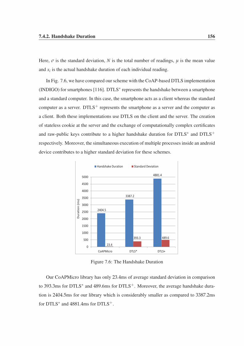
7.4.2. Handshake Duration 156
Here, σ is the standard deviation, N is the total number of readings, μ is the mean value
and xi is the actual handshake duration of each individual reading.
In Fig. 7.6, we have compared our scheme with the CoAP-based DTLS implementation
(INDIGO) for smartphones [116]. DTLS∗ represents the handshake between a smartphone
and a standard computer. In this case, the smartphone acts as a client whereas the standard
computer as a server. DTLS+ represents the smartphone as a server and the computer as
a client. Both these implementations use DTLS on the client and the server. The creation
of stateless cookie at the server and the exchange of computationally complex certificates
and raw-public keys contribute to a higher handshake duration for DTLS∗ and DTLS+
respectively. Moreover, the simultaneous execution of multiple processes inside an android
device contributes to a higher standard deviation for these schemes.
2404.5
3387.2
4881.4
23.4
393.3 489.6
0
500
1000
1500
2000
2500
3000
3500
4000
4500
5000
CoAPMicro DTLS* DTLS+
Dur
atio
n (m
s)
Handshake Duration Standard Deviation
Figure 7.6: The Handshake Duration
Our CoAPMicro library has only 23.4ms of average standard deviation in comparison
to 393.3ms for DTLS∗ and 489.6ms for DTLS+. Moreover, the average handshake dura-
tion is 2404.5ms for our library which is considerably smaller as compared to 3387.2ms
for DTLS∗ and 4881.4ms for DTLS+.

7.4.3. Average Response Time 157
7.4.3 Average Response Time
In our scheme, the CoAP messages are exchanged asynchronously over the UDP sockets.
Each client maintains the record of the transmitted CON request messages to keep track of
their transit through the network. When a matching acknowledgement or a reset response
is received for such messages, the exchange is considered as successful.
In Fig. 7.7(a), the average response time for each message is computed for a server
handling multiple requests at a given time. The response time increases with the increase
of simultaneously transmitted messages. When the number of such requests (n) is 100, the
response time is significantly higher which can ultimately cause congestion and scarcity
of resources to the clients in the network. The response time is considerably lower when
n is 20 or 50. Furthermore, the payload size has little impact on the average response time
for these values of n. In Fig. 7.7(b), the average response time for a single confirmable
message of 1 byte is compared with those of the DTLS and the CoAP protocol with no se-
curity. As explained previously, the presence of certificates, raw-public keys and expensive
flight-based authentication makes DTLS as an expensive choice for the interacting objects
in an IoT platform.
0
1000
2000
3000
4000
5000
6000
7000
1 64 128 256 512
Ave
rag
e R
esp
on
se T
ime
(m
s)
Payload [byte]
n=20 n=50 n=100
(a) Simultaneous Transmissions
25
123
219
0
50
100
150
200
250
NoSec CoAPMicro DTLS
Aver
age
Resp
onse
Tim
e (m
s)
(b) Response Time at 1 Byte Payload
Figure 7.7: The Average Response Time
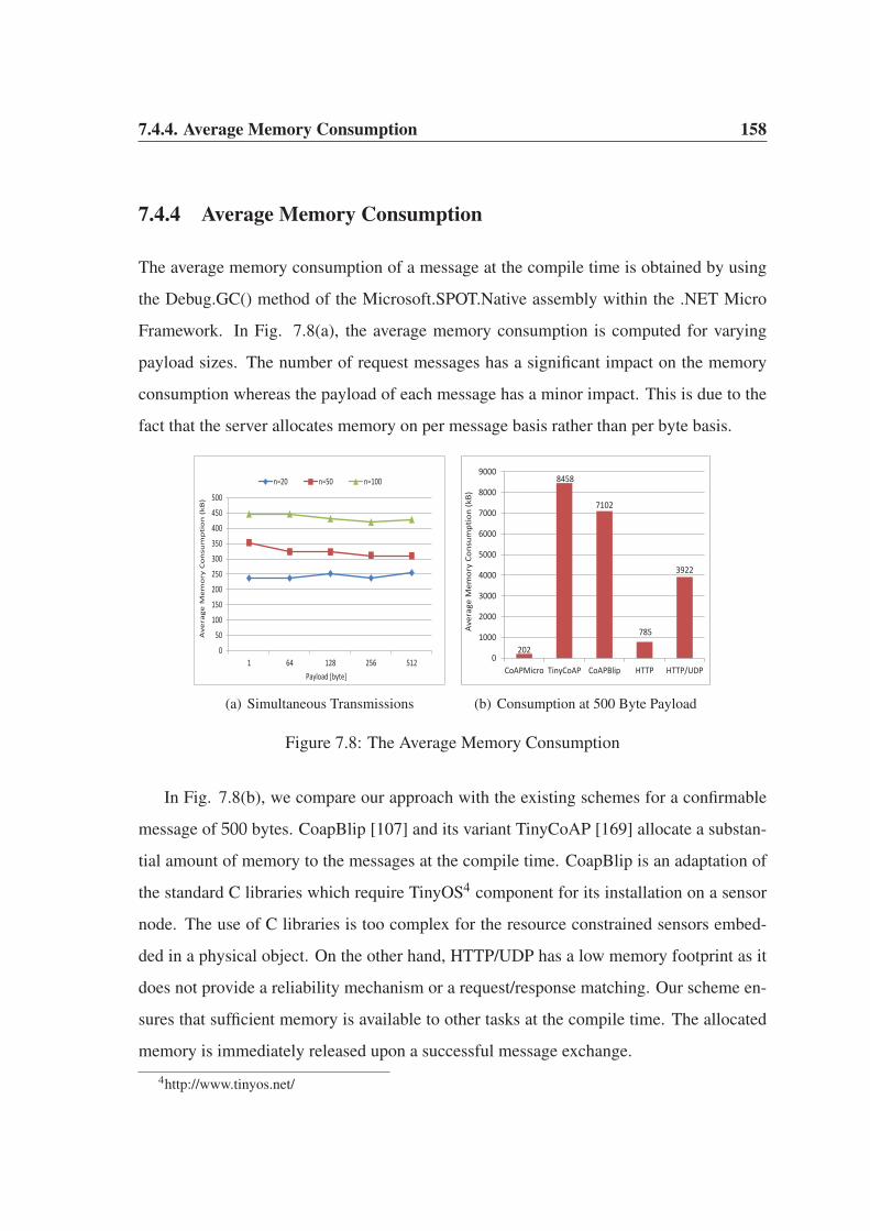
7.4.4. Average Memory Consumption 158
7.4.4 Average Memory Consumption
The average memory consumption of a message at the compile time is obtained by using
the Debug.GC() method of the Microsoft.SPOT.Native assembly within the .NET Micro
Framework. In Fig. 7.8(a), the average memory consumption is computed for varying
payload sizes. The number of request messages has a significant impact on the memory
consumption whereas the payload of each message has a minor impact. This is due to the
fact that the server allocates memory on per message basis rather than per byte basis.
0
50
100
150
200
250
300
350
400
450
500
1 64 128 256 512
Ave
rag
e M
em
ory
Co
nsu
mp
tio
n (
kB)
Payload [byte]
n=20 n=50 n=100
(a) Simultaneous Transmissions
202
8458
7102
785
3922
0
1000
2000
3000
4000
5000
6000
7000
8000
9000
CoAPMicro TinyCoAP CoAPBlip HTTP HTTP/UDP
Ave
rage
Mem
ory
Cons
umpt
ion
(kB)
(b) Consumption at 500 Byte Payload
Figure 7.8: The Average Memory Consumption
In Fig. 7.8(b), we compare our approach with the existing schemes for a confirmable
message of 500 bytes. CoapBlip [107] and its variant TinyCoAP [169] allocate a substan-
tial amount of memory to the messages at the compile time. CoapBlip is an adaptation of
the standard C libraries which require TinyOS4 component for its installation on a sensor
node. The use of C libraries is too complex for the resource constrained sensors embed-
ded in a physical object. On the other hand, HTTP/UDP has a low memory footprint as it
does not provide a reliability mechanism or a request/response matching. Our scheme en-
sures that sufficient memory is available to other tasks at the compile time. The allocated
memory is immediately released upon a successful message exchange.
4http://www.tinyos.net/

7.4.5. Detection of Replay Attacks 159
7.4.5 Detection of Replay Attacks
As an application layer protocol, CoAP is exposed to various denial-of-service (DoS) at-
tacks. Even in the presence of an authentication scheme, intruders always try to sneak into
a network to conduct malicious activities. The number of such activities increases with
the increase in the number of intruders in the network. In Table 7.3, the number of replay
attacks is computed over a period of 60 seconds.
Time (sec) Intruder A Intruder B
0-10 3 5
11-20 6 2
21-30 3 4
31-40 4 0
41-50 1 2
51-60 7 6
Table 7.3: Number of Detected Replay Attacks
Here, intruder A conducts 24 attacks whereas intruder B conducts 19 such attempts
over the same period of time. The detection of replay attacks is based on the freshness of
the notification messages as discussed in Section 7.3.
7.5 Summary
Advances in WSN, RFID, wireless and cellular networks have enabled real-world objects
to generate data on an unprecedented scale. This chapter takes sensor nodes one step fur-
ther by integrating them in real-world physical objects to form an Internet of Things (IoT).
The presence of a sensor node and an IP address make an object smart enough to interact
in the real-world. The data generated by various physical objects is susceptible to a wide
range of security threats at different layers. The presence of sensor nodes at the core of
each physical object requires lightweight but robust authentication and security protocols.
The scope of this chapter is twofold. First, a payload-based authentication scheme is pro-
posed to verify the identities of the communicating clients and server in the network. It

7.5. Summary 160
uses a simple handshake procedure to exchange the session key for the resource observa-
tion. The proposed approach uses pre-shared keys for the identity verification of objects.
These keys are known only to legitimate objects and cannot be obtained illicitly in view of
the Internet Threat Model. Second, this chapter talks about the application of the proposed
scheme for detection of replay attack, eavesdropping and resource exhaustion of a server.
The lightweight features of CoAP protocol are used to provide an efficient exchange of re-
sources while secure features of MicroCoAP validates the identities of participating clients
and server.

Chapter 8
Conclusion and Future Work
Wireless Sensor Networks (WSNs) have the ability to operate in remote and hazardous lo-
cations which cannot be monitored with traditional Internet. The use of these networks for
monitoring the state of physical environment is promising yet challenging. WSNs com-
prise of resource-starving sensor nodes which provide an interface between the physical
world events and the virtual world of information. The nodes face various challenges at
different layers and such challenges are addressed in this thesis. In sensor networks, min-
imization of energy consumption of sensor nodes has attracted a lot of research. Such
approaches effectively enhance the lifetime of these networks. In this thesis, we focused
on designing efficient routing protocols. This thesis also investigated and proposed secure
schemes to conserve the energy of nodes. Efficient routing protocols reduce the energy
consumption by various means such as reducing the number of transmission hops, ef-
ficient data aggregation, scheduling the duty-cycling of nodes and collision avoidance.
On the other hand, secure and robust schemes also reduce energy consumption because
safeguarding the nodes or networks from malicious attacks literally mean to enhance the
network lifetime. For example, in Sybil attack, the forged identities inject malicious data
in the network which increases the energy consumption of legitimate nodes in data pro-
cessing, aggregation and transmission. Similarly in replay attack, an adversary replay

162
out-dated data which again affects the energy consumption of legitimate nodes. The use of
sophisticated protection schemes not only protect the networks from malicious activities
but also enhance their lifetime. Moreover, these sensor nodes are used as part of Internet
of Things (IoT) by embedding them in everyday physical world objects for data collection.
The IoT has the ability to collect a huge stream of data which may poses further challenges
for the cloud computing and Big data. Therefore, robust and secure solutions are required
to address such challenges.
To achieve the aforementioned objectives, we have conducted in-depth research on
energy-efficient cluster-based hierarchical routing protocols and robust secure solutions in
this thesis. A summary of the research conducted for this thesis is provided in this section
followed by potential future works. We provide a summary of all the chapters and their
findings.
In Chapter 2, a detailed description of Wireless Sensor Network (WSNs) and their ap-
plications has been presented. The drawbacks of conventional routing protocols in WSNs
were highlighted which motivate us to use cluster-based hierarchical routing protocols for
our research. A brief overview of various congestion detection and mitigation techniques
in WSNs was presented and their shortcomings were highlighted. The existing research
on various Sybil attack detection schemes was presented which refines our objective to
develop such a scheme for a centralized cluster-based hierarchical network. Chapter 2 also
presents scenario for forest wildfire monitoring application and the need for a Sybil attack
detection scheme in such applications. We conclude this chapter with a detailed discussion
on the Internet of Things (IoT), it’s fascinating applications, CoAP and the existing works
on various security schemes to protect the object in an IoT paradigm.
Chapter 3 proposed two different routing algorithms for cluster-based hierarchical
WSNs. The first algorithm uses a randomly distributed approach for cluster head selection
and aims at improving network lifetime and quality of data. In a randomly distributed
approach, each node autonomously elects itself as a cluster head based on a probabilistic
163
threshold value. Our proposed approach considers the residual energy of each node as the
main criteria for cluster head selection. As a result, nodes having higher residual energy
values are frequently elected as cluster heads which enhance the lifetime of the network
as compared to LEACH protocol. Moreover, the proposed algorithm achieves better data
aggregation results as compared to LEACH protocol, which in turn affect the quality of
delivered data at the base station. The second algorithm uses a centralized approach in
which the base station decides an optimal percentage of cluster heads for each round. Un-
like the existing centralized approaches, our approach does not require cluster heads to
advertise themselves. Moreover, the transmission of join-request messages is eliminated.
Once a cluster-based hierarchical network is formed, an energy evaluation model is devel-
oped which takes into account the energy consumption of nodes during various phases and
sub-phases.
Chapter 4 proposed PASCCC protocol which uses randomly distributed cluster-based
hierarchical algorithm presented in Chapter 3. This scheme has been used to detect conges-
tion in cluster-based hierarchical WSNs. PASCCC is an application-specific and priority-
driven protocol which monitors two different applications, i.e., temperature and humidity,
based on their assigned levels of priorities. The protocol provides an on-demand mobil-
ity to cover vacant regions left behind by the energy-starved depleted nodes. The use of
on-demand mobility ensures that time-critical and delay-sensitive events are not lost. Dur-
ing congestion, higher priority temperature packets are routed from congested clusters to
the base station without further delay. Moreover, lower priority humidity packets are in-
stantly dropped to reduce the level of congestion. PASCCC uses a novel queuing model
which drops the packets based on the assigned priority levels, threshold values and type of
nodes, i.e., queuing model of a member node is different from the cluster head. The use
of threshold values efficiently schedule the duty-cycling of each node which enhances the
network lifetime as compared to the existing protocols. PASCCC is an optimal choice for
monitoring various threshold-dependent applications.
Chapter 5 proposed a lightweight scheme for Sybil attack detection and its application

164
to a centralized cluster-based hierarchical network. The proposed scheme detects Sybil
nodes based on the RSSI of received control packets. A small percentage of high energy
nodes are assigned the task of detection. They assist the base station in Sybil attack detec-
tion and enable it to prevent such nodes from participation in cluster head selection. Each
candidate node for a cluster head is evaluated based on its residual energy, geographical
location and previous history of selection. The use of a centralized approach ensures that
an optimal percentage of cluster heads are elected in each round. The optimal selection
of cluster heads enhances network lifetime, packet loss rate and packet acceptance ratio.
Moreover, the proposed scheme detects the number of Sybil nodes and their forged identi-
ties which give a rough estimation of the average number of identities forged by each Sybil
node in each round.
In Chapter 6, two different detection techniques, i.e., two-tier and residual energy-
based schemes, for Sybil attack within a forest wildfire monitoring application were stud-
ied. The two-tier detection technique uses high energy nodes operating at a lower level
to detect forged identities of Sybil nodes. However, due to the hostile environment in a
forest, one or more identities may sneak through the detection process. These identities
are ultimately detected by the two base stations operating at a higher level. A residual
energy-based detection technique uses the residual energy of each node to detect a possi-
ble Sybil attack at the high energy nodes. If two or more incoming control packets have the
same residual energy but different identities, it means that a Sybil attack has been launched
by an adversary. After Sybil attack detection, an optimal percentage of cluster heads are
selected by the base stations using a centralized approach. Each cluster head is assigned
a spatial query to collect data about the environmental parameters within a forest. The
data collected from member nodes may either belong to normal nodes or sneaked identi-
ties of Sybil nodes. To deceive an end user, the sneaked Sybil identities may broadcast
high volume of false-negative alerts. The two base stations remain vigilant to prevent any
such alerts from reaching an end user. Only incoming genuine alerts from normal nodes
are analysed and if any of them are of significant importance, the base stations assign on-
8.1. Future Work 165
demand queries to the origin of those alerts, i.e. the source nodes. The proposed techniques
have a better network lifetime, detection rate, accuracy, data aggregation, data fusion and
coverage as compared to the existing schemes.
In Chapter 7, a payload-based authentication scheme was proposed which verifies the
identities of the objects in an IoT environment. The objects in the roles of clients and
server, communicate with each other for exchanging the resources. The identity is pro-
vided to each object by a miniature sensor node embedded in it. However, the presence
of embedded sensor nodes requires lightweight communication protocols to optimize the
usage of resources. As a result, our proposed scheme uses a simple handshake procedure
to exchange the session key for the resource observation. The proposed approach uses
pre-shared keys for the identity verification of the objects. These keys are known only to
legitimate objects and cannot be obtained illicitly in view of the Internet Threat Model.
The proposed scheme is feasible to detect various types of attacks such as, replay, eaves-
dropping and resource exhaustion. Our scheme is extremely lightweight and incurs less
overhead and exhibits much lower handshake duration. Moreover, the average memory
consumption and average response time is much lower than the existing schemes which
are currently used for securing the objects in an IoT paradigm.
8.1 Future Work
Wireless Sensor Networks (WSNs) possess some unique characteristics such as self-healing,
self-organizing, fault-tolerance, low duty-cycling, dynamic network topology, energy har-
vesting and operation in human-inaccessible terrains. These unique characteristics have
broadened the scope of these networks. As a result, they have found their presence in a
wide range of applications. In WSNs, the nodes are low on various resources such as bat-
tery power, storage, computation, data rate and transmission range. These networks face
various challenges during operation due to the presence of these miniature sensor nodes.
To address these challenges, WSNs have attracted a significant amount of research from

8.1. Future Work 166
academia and industry. In fact, researchers are continuously working on addressing a myr-
iad of challenges that have spawned from the resource limitation imposed on the sensor
nodes. At first glance, it seems that cluster-based hierarchical routing protocols are the
solution for addressing all the limitations of WSNs. However, these protocols also have
their own limitations which need to be further investigated.
Regardless of randomly distributed or centralized approaches, almost all of the cluster-
based hierarchical routing protocols are designed for conceptual WSNs, i.e., these proto-
cols do not address any real-time application. These protocols have the potential to opti-
mize the usage of various resources but they need to be implemented with real-time appli-
cations, such as battlefield surveillance, agriculture monitoring, industrial automation and
healthcare monitoring. Almost all, these real-time applications use conventional routing
techniques in which hop-by-hop and end-to-end communication is used for data delivery
to a base station. QoS provisioning is a challenging task in these applications and the use
of cluster-based hierarchical routing protocols for these applications will have a significant
impact on their performance if proper care on resource management is not taken with due
care. However, these protocols need to satisfy the QoS requirements of these applications.
The distinguishing features of these protocols, i.e., load balancing, fault-tolerance, power
optimization, data aggregation, collision avoidance and prolonging network lifetime, will
facilitate these applications in long run. Our contributions in Chapter 4 and Chapter 6 used
cluster-based hierarchical routing protocols as the underlying platforms for monitoring a
real-time application, i.e., forest wildfire monitoring. Although, these chapters addressed
congestion and security challenges in a real-time application but, the ultimate goal was to
optimize the usage of resources. In other words, both these chapters enhanced QoS param-
eters such as network lifetime, energy consumption, delay, congestion and throughput. To
this end, cluster-based hierarchical routing protocols were applied to a real-world applica-
tion and various QoS parameters were enhanced. However, both these chapters have their
own shortcomings. In Chapter 4, the queuing model of PASCCC protocol was developed
for a single time-critical application. It would be interesting to see the behaviour of the
8.1. Future Work 167
queue in presence of more than one time-critical application. Moreover, the behaviour of
the queue needs to be analysed in presence of leaky bucket algorithm which maintains the
flow of data and ensures that the available bandwidth is utilized efficiently. Furthermore,
the nature of the traffic arrival process exhibits a bursty and correlated behaviour, which
degrades the network performance. All these factors, i.e., queue scheduling, number of
queues, queuing threshold, traffic arrival rate and network performance contribute toward
the QoS of any real-time application. In Chapter 6, a Sybil attack detection technique was
designed for a forest wildfire monitoring application. Although, the main objective was to
address the security challenges faced by the nodes within a forest, however, our proposed
scheme achieved better QoS metrics as well. In fact, it is the aim of any design scheme
for a WSN, that it must be secure, robust and efficient in term of resource usage. Our
proposed scheme enhances the optimization of resources and at the same time, is highly
efficient in terms of detection of Sybil nodes. However, the selection of cluster heads is
computationally complex and a large overhead is involved which may be improved further
using a rather simple logic. These performance metrics involving computational complex-
ity and delay incurred in cluster head selection may be enhanced through future research
investigation.
The Internet of Things (IoT) represents the next generation of the Internet by taking
a huge leap to gather, analyse and distribute data about the physical world which can be
transformed into information, knowledge and ultimately wisdom. This evolution involves
interconnecting the physical objects from everyday life. Each object requires an identity
to bridge the gap between the virtual world of information and the physical world of ob-
jects. However, the presence of objects in the Internet poses new challenges which were
not known in the past. The addition of such objects is not a straightforward process. Each
object has its own attributes and requirements for network communication. As a result,
interoperability is a major challenging task which needs to be addressed. Despite all the
speculations about the IoT applications and interconnected objects, fewer efforts have been
made to secure IoT products reaching the market. Most of these products lack secure fea-
8.1. Future Work 168
tures. As objects are having different attributes and specifications, hence, secure solutions
available for the conventional Internet are not feasible for these objects. Although, sensor
nodes are involved at the core of communication system in these objects, however, secure
solutions for WSNs are not feasible for these physical objects. The underlying hardware
and software platforms of these objects are incompatible with the sensor nodes. In Chapter
7, we proposed a payload-based authentication scheme which is efficient against various
attacks such as, replay, eavesdropping and resource exhaustion. However, it is yet to be
determined how efficient and robust the scheme is against other types of attacks such as
Sybil, sink-hole, wormhole and black hole. Furthermore, the proposed approach allocates
pre-shared keys at the provisioning phase, hence, it is a suitable choice for a static deploy-
ment. If the pre-shared key of an incoming mobile client is not present in the server lookup
table, the client will not be able to communicate with the server. For this type of scenario, a
dynamic key allocation scheme may be a more optimal choice. This is specifically the case
with a large scale deployment of IoT objects in real life situations. The scalability and mo-
bility of the nodes may further improve the proposed scheme and broaden its future scope
of application.
Currently, we are focusing on the integration of LEACH protocol with CoAP for the
objects communicating in an IoT environment. Presently, most of the CoAP-based objects
in an IoT paradigm rely on 6LoWPAN at network layer and IEEE 802.15.4 standard at
data link (MAC) and physical (PHY) layers. We aim to implement a protocol stack which
uses CoAP at application layer and LEACH at network layer. We will compare the perfor-
mance of the scheme against the existing schemes. Furthermore, we also aim to eliminate
the use of IEEE 802.15.4 standard at MAC and PHY layers. LEACH has the ability to
provide standalone services which literally means that all the services required at MAC
and PHY layers may be provided by LEACH as well. Another fascinating area for future
research work is congestion detection within a forest wildfire monitoring application using
a cluster-based hierarchical routing protocol. Our PASCCC protocol reduces congestion
in overcrowded clusters by using threshold levels at the nodes, i.e., nodes drop humidity

8.1. Future Work 169
packets and route time-critical, delay sensitive temperature packets at the time of conges-
tion. The proposed scheme can be improved further if the cluster heads in the congested
clusters borrow communication channels from those clusters where density of the nodes
is low. The cluster heads in uncongested clusters have ample of communication channels
available which can be provided to cluster heads in congested clusters.
This thesis first addressed energy conservation issues faced by sensor nodes in WSN
followed by designing secured schemes to tackle Sybil attack. Both these objectives aim to
prolong the lifetime of a network. Designing energy-efficient routing techniques conserve
the energy of sensor nodes in sensing, transmission and data aggregation. On the other
hand, robust security schemes protect the network from malicious activities of an attacker.
In a secured network, packet drop ratio is low which means that the nodes require fewer re-
transmission attempts. Each retransmission attempt consumes the energy of sensor nodes
in transmission, in-network processing at the intermediate nodes, and data aggregation.
Moreover, the number of retransmission attempts increases the possibility of congestion in
the network which ultimately leads to higher delay and low network throughput. The pres-
ence of sensor nodes at the core of each real-world physical object imposes the resource-
limitations on these objects. The existing energy-efficient and security schemes of Internet
cannot be applied to IoT because each object has its own distinguishing attributes and char-
acteristics. As a result, new authentication and security schemes need to be designed for
the interacting objects in an IoT environment.
Bibliography
[1] J. Yick, B. Mukherjee, and D. Ghosal, “Wireless sensor network survey,” Computer
networks, vol. 52, no. 12, pp. 2292–2330, 2008.
[2] W. W. Dargie and C. Poellabauer, Fundamentals of wireless sensor networks: theory
and practice. John Wiley & Sons, 2010.
[3] J. Gutierrez, J. F. Villa-Medina, A. Nieto-Garibay, and M. A. Porta-Gandara, “Auto-
mated irrigation system using a wireless sensor network and gprs module,” Instru-
mentation and Measurement, IEEE Transactions on, vol. 63, no. 1, pp. 166–176,
2014.
[4] J. M. Corchado, J. Bajo, D. Tapia, A. Abraham, et al., “Using heterogeneous wire-
less sensor networks in a telemonitoring system for healthcare,” Information Tech-
nology in Biomedicine, IEEE Transactions on, vol. 14, no. 2, pp. 234–240, 2010.
[5] Y. E. Aslan, I. Korpeoglu, and O. Ulusoy, “A framework for use of wireless sen-
sor networks in forest fire detection and monitoring,” Computers, Environment and
Urban Systems, vol. 36, no. 6, pp. 614–625, 2012.
[6] K. K. Khedo, R. Perseedoss, A. Mungur, et al., “A wireless sensor network air
pollution monitoring system,” arXiv preprint arXiv:1005.1737, 2010.

Bibliography 171
[7] J. Rezazadeh, “Mobile wireless sensor networks overview,” International Journal
of Computer Communications and Networks, vol. 2, no. 1, pp. 17–22, 2012.
[8] S. A. Munir, B. Ren, W. Jiao, B. Wang, D. Xie, and J. Ma, “Mobile wireless sensor
network: Architecture and enabling technologies for ubiquitous computing,” in 21st
International Conference on Advanced Information Networking and Applications
Workshops, AINAW’07, pp. 113–120, IEEE, 2007.
[9] I. Amundson and X. D. Koutsoukos, “A survey on localization for mobile wireless
sensor networks,” in Proceedings of the Second International Conference on Mobile
Entity Localization and Tracking in GPS-less Environments, (Berlin, Heidelberg),
pp. 235–254, Springer-Verlag, 2009.
[10] R. C. Shah, S. Roy, S. Jain, and W. Brunette, “Data mules: Modeling and analysis
of a three-tier architecture for sparse sensor networks,” Ad Hoc Networks, vol. 1,
no. 2, pp. 215–233, 2003.
[11] K. Akkaya and M. Younis, “A survey on routing protocols for wireless sensor net-
works,” Ad hoc networks, vol. 3, no. 3, pp. 325–349, 2005.
[12] G. Shafiullah, A. Gyasi-Agyei, and P. J. Wolfs, “A survey of energy-efficient and
qos-aware routing protocols for wireless sensor networks,” in Novel algorithms and
techniques in telecommunications, automation and industrial electronics, pp. 352–
357, Springer, 2008.
[13] S. Tang and W. Li, “Qos supporting and optimal energy allocation for a cluster based
wireless sensor network,” Computer Communications, vol. 29, no. 13, pp. 2569–
2577, 2006.
[14] O. B. Akan and I. F. Akyildiz, “Event-to-sink reliable transport in wireless sensor
networks,” IEEE/ACM Transactions on Networking (TON), vol. 13, no. 5, pp. 1003–
1016, 2005.
[15] A. Perrig, R. Szewczyk, J. D. Tygar, V. Wen, and D. E. Culler, “Spins: Security
protocols for sensor networks,” Wireless networks, vol. 8, no. 5, pp. 521–534, 2002.
Bibliography 172
[16] X. Liu, “A survey on clustering routing protocols in wireless sensor networks,” Sen-
sors, vol. 12, no. 8, pp. 11113–11153, 2012.
[17] S. H. Lee, S. Lee, H. Song, and H. S. Lee, “Gradual cluster head election for high
network connectivity in large-scale sensor networks,” in Advanced Communication
Technology (ICACT), 2011 13th International Conference on, pp. 168–172, IEEE,
2011.
[18] L. Chitnis, A. Dobra, and S. Ranka, “Fault tolerant aggregation in heterogeneous
sensor networks,” Journal of Parallel and Distributed Computing, vol. 69, no. 2,
pp. 210–219, 2009.
[19] V. Tran-Quang and T. Miyoshi, “A transmission range adjustment algorithm to avoid
energy holes in wireless sensor networks,” in Information and Telecommunication
Technologies (APSITT), 2010 8th Asia-Pacific Symposium on, pp. 1–6, IEEE, 2010.
[20] L. Atzori, A. Iera, and G. Morabito, “The internet of things: A survey,” Computer
networks, vol. 54, no. 15, pp. 2787–2805, 2010.
[21] J. Gubbi, R. Buyya, S. Marusic, and M. Palaniswami, “Internet of things (iot): A
vision, architectural elements, and future directions,” Future Generation Computer
Systems, vol. 29, no. 7, pp. 1645–1660, 2013.
[22] M. Becker, T. Potsch, K. Kuladinithi, and C. Goerg, “Deployment of coap in trans-
port logistics,” in Proceedings of the 36th IEEE Conference on Local Computer
Networks (LCN). Bonn Germany 2011, 2011.
[23] O. Bergmann, K. T. Hillmann, and S. Gerdes, “A coap-gateway for smart homes,”
in 2012 International Conference on Computing, Networking and Communications
(ICNC), pp. 446–450, IEEE, 2012.
[24] M. Castro, A. J. Jara, and A. F. Skarmeta, “Enabling end-to-end coap-based com-
munications for the web of things,” Journal of Network and Computer Applications,
2014.

Bibliography 173
[25] M. Becker, K. Kuladinithi, T. Potsch, and C. Gorg, “Wireless freight supervision
using open standards,” in 5 th International Workshop Cold Chain Management.
June, pp. 10–11, 2013.
[26] M. Kovatsch, “Firm firmware and apps for the internet of things,” in Proceedings
of the 2nd Workshop on Software Engineering for Sensor Network Applications,
pp. 61–62, ACM, 2011.
[27] Y. Li and R. Bartos, “A survey of protocols for intermittently connected delay-
tolerant wireless sensor networks,” Journal of Network and Computer Applications,
vol. 41, pp. 411–423, 2014.
[28] M. DI and G. Tsudik, “Security and privacy in emerging wireless networks,” IEEE
Wireless Communications, pp. 13–21, 2010.
[29] A.-S. K. Pathan, H.-W. Lee, and C. S. Hong, “Security in wireless sensor networks:
issues and challenges,” in The 8th International Conference Advanced Communica-
tion Technology, 2006. ICACT 2006., vol. 2, pp. 6–pp, IEEE, 2006.
[30] J. Newsome, E. Shi, D. Song, and A. Perrig, “The sybil attack in sensor networks:
analysis & defenses,” in Proceedings of the 3rd international symposium on Infor-
mation processing in sensor networks, pp. 259–268, ACM, 2004.
[31] Z. Zhao, B. Wei, X. Dong, L. Yao, and F. Gao, “Detecting wormhole attacks in wire-
less sensor networks with statistical analysis,” in 2010 WASE International Confer-
ence on Information Engineering (ICIE), vol. 1, pp. 251–254, IEEE, 2010.
[32] I. Krontiris, T. Giannetsos, and T. Dimitriou, “Launching a sinkhole attack in wire-
less sensor networks; the intruder side,” in IEEE International Conference on Wire-
less and Mobile Computing Networking and Communications, 2008. WIMOB’08.,
pp. 526–531, IEEE, 2008.
[33] B. Yu and B. Xiao, “Detecting selective forwarding attacks in wireless sensor net-
works,” in Parallel and Distributed Processing Symposium, 2006. IPDPS 2006. 20th
International, pp. 8–pp, IEEE, 2006.
Bibliography 174
[34] D. R. Raymond and S. F. Midkiff, “Denial-of-service in wireless sensor networks:
Attacks and defenses,” Pervasive Computing, IEEE, vol. 7, no. 1, pp. 74–81, 2008.
[35] R. Roman, P. Najera, and J. Lopez, “Securing the internet of things,” Computer,
vol. 44, no. 9, pp. 51–58, 2011.
[36] C. T. Ee and R. Bajcsy, “Congestion control and fairness for many-to-one routing in
sensor networks,” in Proceedings of the 2nd international conference on Embedded
networked sensor systems, pp. 148–161, ACM, 2004.
[37] J. Zheng and A. Jamalipour, Wireless sensor networks: a networking perspective.
John Wiley & Sons, 2009.
[38] N. Pantazis, S. A. Nikolidakis, and D. D. Vergados, “Energy-efficient routing proto-
cols in wireless sensor networks: A survey,” Communications Surveys & Tutorials,
IEEE, vol. 15, no. 2, pp. 551–591, 2013.
[39] N. Zaman, Wireless Sensor Networks and Energy Efficiency: Protocols, Routing
and Management: Protocols, Routing and Management. IGI Global, 2012.
[40] R. Tan, G. Xing, J. Chen, W.-Z. Song, and R. Huang, “Fusion-based volcanic earth-
quake detection and timing in wireless sensor networks,” ACM Transactions on Sen-
sor Networks (TOSN), vol. 9, no. 2, p. 17, 2013.
[41] I. F. Akyildiz, W. Su, Y. Sankarasubramaniam, and E. Cayirci, “A survey on sensor
networks,” IEEE Communications magazine, vol. 40, no. 8, pp. 102–114, 2002.
[42] M. Li and Y. Liu, “Underground structure monitoring with wireless sensor net-
works,” in Proceedings of the 6th international conference on Information process-
ing in sensor networks, pp. 69–78, ACM, 2007.
[43] H. Chang et al., “Underwater wireless sensor networks,” in Oceans, 2012, pp. 1–5,
IEEE, 2012.

Bibliography 175
[44] S. M. Aziz and D. M. Pham, “Energy efficient image transmission in wireless mul-
timedia sensor networks,” IEEE Communications Letters, vol. 17, no. 6, pp. 1084–
1087, 2013.
[45] R. C. Luo and O. Chen, “Mobile sensor node deployment and asynchronous power
management for wireless sensor networks,” IEEE Transactions on Industrial Elec-
tronics, vol. 59, no. 5, pp. 2377–2385, 2012.
[46] T. He, P. Vicaire, T. Yan, L. Luo, L. Gu, G. Zhou, R. Stoleru, Q. Cao, J. Stankovic,
T. Abdelzaher, et al., “Achieving real-time target tracking usingwireless sensor net-
works,” in Proceedings of the 12th IEEE Real-Time and Embedded Technology and
Applications Symposium, 2006., pp. 37–48, IEEE, 2006.
[47] K. Sohraby, D. Minoli, and T. Znati, Wireless sensor networks: technology, proto-
cols, and applications. John Wiley & Sons, 2007.
[48] C.-H. Lu and L.-C. Fu, “Robust location-aware activity recognition using wireless
sensor network in an attentive home,” IEEE Transactions on Automation Science
and Engineering, vol. 6, no. 4, pp. 598–609, 2009.
[49] P. Juang, H. Oki, Y. Wang, M. Martonosi, L. S. Peh, and D. Rubenstein, “Energy-
efficient computing for wildlife tracking: Design tradeoffs and early experiences
with zebranet,” ACM Sigplan Notices, vol. 37, no. 10, pp. 96–107, 2002.
[50] M. Hamdi, N. Boudriga, and M. S. Obaidat, “Whomoves: An optimized broadband
sensor network for military vehicle tracking,” International Journal of Communica-
tion Systems, vol. 21, no. 3, pp. 277–300, 2008.
[51] F. Viani, L. Lizzi, P. Rocca, M. Benedetti, M. Donelli, and A. Massa, “Object track-
ing through rssi measurements in wireless sensor networks,” Electronics Letters,
vol. 44, no. 10, pp. 653–654, 2008.
[52] X. Li, Y. Deng, and L. Ding, “Study on precision agriculture monitoring framework
based on wsn,” in 2nd International Conference on Anti-counterfeiting, Security and
Identification, 2008. ASID 2008., pp. 182–185, IEEE, 2008.

Bibliography 176
[53] D. Christin, P. S. Mogre, and M. Hollick, “Survey on wireless sensor network tech-
nologies for industrial automation: The security and quality of service perspectives,”
Future Internet, vol. 2, no. 2, pp. 96–125, 2010.
[54] A. Bielsa and M. Boyd, Wireless Sensor Networks to monitor food sustainability,
2012.
[55] S. Kaplantzis, N. Mani, M. Palaniswanmi, and G. Egan, “Security models for wire-
less sensor networks,” PhD Conversion Report, Centre of Telecommunications and
Information Engineering, Monash University, Australia, 2006.
[56] C. O. Mathuna, T. ODonnell, R. V. Martinez-Catala, J. Rohan, and B. OFlynn,
“Energy scavenging for long-term deployable wireless sensor networks,” Talanta,
vol. 75, no. 3, pp. 613–623, 2008.
[57] I. F. Akyildiz, W. Su, Y. Sankarasubramaniam, and E. Cayirci, “Wireless sensor
networks: a survey,” Computer networks, vol. 38, no. 4, pp. 393–422, 2002.
[58] K. R. Fall and W. R. Stevens, TCP/IP illustrated, volume 1: The protocols. addison-
Wesley, 2011.
[59] W. R. Heinzelman, J. Kulik, and H. Balakrishnan, “Adaptive protocols for infor-
mation dissemination in wireless sensor networks,” in Proceedings of the 5th an-
nual ACM/IEEE international conference on Mobile computing and networking,
pp. 174–185, ACM, 1999.
[60] S. M. Hedetniemi, S. T. Hedetniemi, and A. L. Liestman, “A survey of gossiping and
broadcasting in communication networks,” Networks, vol. 18, no. 4, pp. 319–349,
1988.
[61] W. R. Heinzelman, A. Chandrakasan, and H. Balakrishnan, “Energy-efficient com-
munication protocol for wireless microsensor networks,” in Proceedings of the 33rd
annual Hawaii international conference on System sciences, 2000, pp. 10–pp, IEEE,
2000.

Bibliography 177
[62] A. Depedri, A. Zanella, and R. Verdone, “An energy efficient protocol for wire-
less sensor networks,” Autonomous Intelligent Networks and Systems (AINS 2003),
Menlo Park, CA, pp. 1–6, 2003.
[63] F. Xiangning and S. Yulin, “Improvement on leach protocol of wireless sensor net-
work,” in International Conference on Sensor Technologies and Applications, 2007.
SensorComm 2007., pp. 260–264, IEEE, 2007.
[64] L. Qing, Q. Zhu, and M. Wang, “Design of a distributed energy-efficient clustering
algorithm for heterogeneous wireless sensor networks,” Computer communications,
vol. 29, no. 12, pp. 2230–2237, 2006.
[65] O. Younis and S. Fahmy, “Heed: a hybrid, energy-efficient, distributed clustering
approach for ad hoc sensor networks,” IEEE Transactions on Mobile Computing,
vol. 3, no. 4, pp. 366–379, 2004.
[66] W. B. Heinzelman, A. P. Chandrakasan, and H. Balakrishnan, “An application-
specific protocol architecture for wireless microsensor networks,” IEEE Transac-
tions on Wireless Communications, vol. 1, no. 4, pp. 660–670, 2002.
[67] S. Varma, N. Nigam, and U. Tiwary, “Base station initiated dynamic routing proto-
col for heterogeneous wireless sensor network using clustering,” in Fourth Interna-
tional Conference on Wireless Communication and Sensor Networks, 2008. WCSN
2008., pp. 1–6, IEEE, 2008.
[68] M. A. Jan, P. Nanda, and X. He, “Energy evaluation model for an improved central-
ized clustering hierarchical algorithm in wsn,” in Wired/Wireless Internet Commu-
nication, pp. 154–167, Springer, 2013.
[69] A. D. Rathnayaka and V. M. Potdar, “Wireless sensor network transport protocol:
A critical review,” Journal of Network and Computer Applications, vol. 36, no. 1,
pp. 134–146, 2013.
[70] U. D. Protocol, “Rfc 768 j. postel isi 28 august 1980,” Isi, 1980.

Bibliography 178
[71] J. Postel, “Rfc 793: Transmission control protocol, september 1981,” Status: Stan-
dard, vol. 88, 2003.
[72] A. Sharif, V. M. Potdar, and A. D. Rathnayaka, “Erctp: End-to-end reliable and
congestion aware transport layer protocol for heterogeneous wsn,” Scalable Com-
puting: Practice and Experience, vol. 11, no. 4, 2001.
[73] C.-Y. Wan, S. B. Eisenman, and A. T. Campbell, “Coda: congestion detection and
avoidance in sensor networks,” in Proceedings of the First international conference
on Embedded networked sensor systems, pp. 266–279, ACM, 2003.
[74] Y. R. Yang and S. S. Lam, “General aimd congestion control,” in 2000 International
Conference on Network Protocols, 2000. Proceedings., pp. 187–198, IEEE, 2000.
[75] B. Hull, K. Jamieson, and H. Balakrishnan, “Mitigating congestion in wireless sen-
sor networks,” in Proceedings of the Second international conference on Embedded
networked sensor systems, pp. 134–147, ACM, 2004.
[76] Y. Sankarasubramaniam, O. B. Akan, and I. F. Akyildiz, “Esrt: event-to-sink reli-
able transport in wireless sensor networks,” in Proceedings of the Fourth interna-
tional symposium on Mobile Ad hoc Networking & Computing, pp. 177–188, ACM,
2003.
[77] N. Yaakob, I. Khalil, and J. Hu, “Performance analysis of optimal packet size for
congestion control in wireless sensor networks,” in Ninth International Symposium
on Network Computing and Applications (NCA), pp. 210–213, IEEE, 2010.
[78] C. Wang, K. Sohraby, B. Li, and W. Tang, “Issues of transport control protocols for
wireless sensor networks,” in Proceedings of International Conference on Commu-
nications, Circuits and Systems (ICCCAS), vol. 1, pp. 422–426, 2005.
[79] L. Neary, Real ’Sybil’ Admits Multiple Personalities Were Fake, 2011.

Bibliography 179
[80] Y. Yu, K. Li, W. Zhou, and P. Li, “Trust mechanisms in wireless sensor networks:
Attack analysis and countermeasures,” Journal of Network and Computer Applica-
tions, vol. 35, no. 3, pp. 867–880, 2012.
[81] K.-F. Ssu, W.-T. Wang, and W.-C. Chang, “Detecting sybil attacks in wireless sen-
sor networks using neighboring information,” Computer Networks, vol. 53, no. 18,
pp. 3042–3056, 2009.
[82] M. Demirbas and Y. Song, “An rssi-based scheme for sybil attack detection in wire-
less sensor networks,” in Proceedings of the 2006 International Symposium on on
World of Wireless, Mobile and Multimedia Networks, pp. 564–570, IEEE Computer
Society, 2006.
[83] Y. Chen, J. Yang, W. Trappe, and R. P. Martin, “Detecting and localizing identity-
based attacks in wireless and sensor networks,” IEEE Transactions on Vehicular
Technology, vol. 59, no. 5, pp. 2418–2434, 2010.
[84] A. Seshadri, M. Luk, A. Perrig, L. van Doorn, and P. Khosla, “Scuba: Secure code
update by attestation in sensor networks,” in Proceedings of the 5th ACM workshop
on Wireless security, pp. 85–94, ACM, 2006.
[85] Y.-g. Ha, H. Kim, and Y.-c. Byun, “Energy-efficient fire monitoring over cluster-
based wireless sensor networks,” International Journal of Distributed Sensor Net-
works, vol. 2012, 2012.
[86] Y. E. Aslan, I. Korpeoglu, and O. Ulusoy, “A framework for use of wireless sen-
sor networks in forest fire detection and monitoring,” Computers, Environment and
Urban Systems, vol. 36, no. 6, pp. 614–625, 2012.
[87] J. Zhang, W. Li, N. Han, and J. Kan, “Forest fire detection system based on a zigbee
wireless sensor network,” Frontiers of Forestry in China, vol. 3, no. 3, pp. 369–374,
2008.
[88] I. Yoon, D. K. Noh, D. Lee, R. Teguh, T. Honma, and H. Shin, “Reliable wildfire
monitoring with sparsely deployed wireless sensor networks,” in Advanced Infor-

Bibliography 180
mation Networking and Applications (AINA), 2012 IEEE 26th International Con-
ference on, pp. 460–466, IEEE, 2012.
[89] D. Ballari, M. Wachowicz, A. K. Bregt, and M. Manso-Callejo, “A mobility con-
straint model to infer sensor behaviour in forest fire risk monitoring,” Computers,
Environment and Urban Systems, vol. 36, no. 1, pp. 81–95, 2012.
[90] K. Ashton, “That internet of things thing,” RFiD Journal, vol. 22, no. 7, pp. 97–114,
2009.
[91] H. Sundmaeker, P. Guillemin, P. Friess, and S. Woelffle, “Vision and challenges
for realising the internet of things,” Cluster of European Research Projects on the
Internet of Things-CERP IoT, 2010.
[92] G. Kortuem, F. Kawsar, D. Fitton, and V. Sundramoorthy, “Smart objects as building
blocks for the internet of things,” Internet Computing, IEEE, vol. 14, no. 1, pp. 44–
51, 2010.
[93] L. Yan, Y. Zhang, L. T. Yang, and H. Ning, The Internet of things: from RFID to the
next-generation pervasive networked systems. CRC Press, 2008.
[94] D. Evans, “The internet of things: How the next evolution of the internet is changing
everything,” CISCO white paper, vol. 1, p. 14, 2011.
[95] S. E. Deering, “Internet protocol, version 6 (ipv6) specification,” Network Working
Group (RFC 2460), 1998.
[96] G. Montenegro, N. Kushalnagar, J. Hui, and D. Culler, “Transmission of ipv6 pack-
ets over ieee 802.15. 4 networks,” tech. rep., 2007.
[97] G. Mulligan, “The 6lowpan architecture,” in Proceedings of the 4th workshop on
Embedded networked sensors, pp. 78–82, ACM, 2007.
[98] Z. Shelby and C. Bormann, 6LoWPAN: The wireless embedded Internet, vol. 43.
John Wiley & Sons, 2011.

Bibliography 181
[99] D. Guinard and V. Trifa, “Towards the web of things: Web mashups for embedded
devices,” in Workshop on Mashups, Enterprise Mashups and Lightweight Compo-
sition on the Web (MEM 2009), in proceedings of WWW (International World Wide
Web Conferences), Madrid, Spain, p. 15, 2009.
[100] Z. Shelby, K. Hartke, and C. Bormann, “The constrained application protocol
(coap),” IETF (RFC 7252), 2014.
[101] L. Richardson and S. Ruby, RESTful web services. ” O’Reilly Media, Inc.”, 2008.
[102] Z. Shelby, “Constrained restful environments (core) link format,” IETF (RFC 6690),
2012.
[103] R. T. Fielding and R. N. Taylor, “Principled design of the modern web architecture,”
ACM Transactions on Internet Technology (TOIT), vol. 2, no. 2, pp. 115–150, 2002.
[104] W. Colitti, K. Steenhaut, and N. De Caro, “Integrating wireless sensor networks
with the web,” Extending the Internet to Low power and Lossy Networks (IP+ SN
2011), 2011.
[105] U. Hunkeler, H. L. Truong, and A. Stanford-Clark, “Mqtt-sa publish/subscribe pro-
tocol for wireless sensor networks,” in Communication systems software and mid-
dleware and workshops, 2008. comsware 2008. 3rd international conference on,
pp. 791–798, IEEE, 2008.
[106] P. Saint-Andre, “Extensible messaging and presence protocol (xmpp): Core,” IETF
(RFC 6120 ), 2011.
[107] K. Kuladinithi, O. Bergmann, T. Potsch, M. Becker, and C. Gorg, “Implementation
of coap and its application in transport logistics,” Proc. IP+ SN, Chicago, IL, USA,
2011.
[108] M. Kovatsch, M. Weiss, and D. Guinard, “Embedding internet technology for home
automation,” in Emerging Technologies and Factory Automation (ETFA), 2010
IEEE Conference on, pp. 1–8, IEEE, 2010.
Bibliography 182
[109] K. Pelechrinis, M. Iliofotou, and S. V. Krishnamurthy, “Denial of service attacks
in wireless networks: The case of jammers,” Communications Surveys & Tutorials,
IEEE, vol. 13, no. 2, pp. 245–257, 2011.
[110] T. Heer, O. Garcia-Morchon, R. Hummen, S. L. Keoh, S. S. Kumar, and K. Wehrle,
“Security challenges in the ip-based internet of things,” Wireless Personal Commu-
nications, vol. 61, no. 3, pp. 527–542, 2011.
[111] T. Dierks, “The transport layer security (tls) protocol version 1.2,” 2008.
[112] D. McGrew and E. Rescorla, “Datagram transport layer security (dtls) extension
to establish keys for secure real-time transport protocol (srtp),” IETF (RFC 5764),
2010.
[113] K. Hartke, “Practical issues with datagram transport layer security in constrained
environments draft-hartke-dice-practical-issues-00,” IETF work in progress, 2013.
[114] K. Hartke and O. Bergmann, “Datagram transport layer security in constrained en-
vironments,” IETF (CoRE Working Group), 2012.
[115] A. Bhattacharyya, A. Ukil, T. Bose, and A. Pal, “Lightweight mutual authentication
for coap (wip),” draft-bhattacharyya-core-coap-lite-auth-00, 2014.
[116] D. Trabalza, S. Raza, and T. Voigt, “Indigo: Secure coap for smartphones,” in Wire-
less Sensor Networks for Developing Countries, pp. 108–119, Springer, 2013.
[117] O. Bergmann, S. Gerfes, and C. Bormann, “Simple keys for simple smart objects,”
in Workshop on Smart Object Security, 2012.
[118] F. Stajano, “The resurrecting duckling,” in Security Protocols, pp. 183–194,
Springer, 2000.
[119] M. A. Jan, P. Nanda, X. He, Z. Tan, and R. P. Liu in 2014 IEEE 13th Interna-
tional Conference o Trust, Security and Privacy in Computing and Communications
(TrustCom), pp. 205–211, IEEE, 2014.
Bibliography 183
[120] M. A. Jan, P. Nanda, X. He, and R. P. Liu, “Enhancing lifetime and quality of data
in cluster-based hierarchical routing protocol for wireless sensor network,” in 2013
IEEE International Conference on High Performance Computing and Communica-
tions & 2013 IEEE 10th International Conference on Embedded and Ubiquitous
Computing (HPCC EUC), pp. 1400–1407, IEEE, 2013.
[121] G. Anastasi, M. Conti, M. Di Francesco, and A. Passarella, “Energy conservation in
wireless sensor networks: A survey,” Ad hoc networks, vol. 7, no. 3, pp. 537–568,
2009.
[122] W. B. Heinzelman, Application-specific protocol architectures for wireless net-
works. PhD thesis, Massachusetts Institute of Technology, 2000.
[123] Y. S. Cho, J. Kim, W. Y. Yang, and C. G. Kang, MIMO-OFDM wireless communi-
cations with MATLAB. John Wiley & Sons, 2010.
[124] S. K. Singh, M. Singh, D. Singh, et al., “Routing protocols in wireless sensor
networks–a survey,” International Journal of Computer Science & Engineering Sur-
vey (IJCSES) Vol, vol. 1, pp. 63–83, 2010.
[125] R. P. Liu, G. J. Sutton, and I. B. Collings, “Power save with offset listen interval for
ieee 802.11 ah smart grid communications,” in Communications (ICC), 2013 IEEE
International Conference on, pp. 4488–4492, IEEE, 2013.
[126] S. D. Muruganathan, D. C. Ma, R. Bhasin, A. O. Fapojuwo, et al., “A centralized
energy-efficient routing protocol for wireless sensor networks,” IEEE Communica-
tions Magazine, vol. 43, no. 3, pp. S8–13, 2005.
[127] A. Kusdaryono and K.-O. Lee, “A clustering protocol with mode selection for wire-
less sensor network,” Journal of Information Processing Systems, vol. 7, no. 1,
pp. 29–42, 2011.
[128] T. Murata and H. Ishibuchi, “Performance evaluation of genetic algorithms for flow-
shop scheduling problems,” in Proceedings of the First IEEE Conference on Evolu-

Bibliography 184
tionary Computation, 1994. IEEE World Congress on Computational Intelligence.,
pp. 812–817, IEEE, 1994.
[129] P. K. Agarwal and C. M. Procopiuc, “Exact and approximation algorithms for clus-
tering,” Algorithmica, vol. 33, no. 2, pp. 201–226, 2002.
[130] O. Boyinbode, H. Le, and M. Takizawa, “A survey on clustering algorithms for
wireless sensor networks,” International Journal of Space-Based and Situated Com-
puting, vol. 1, no. 2, pp. 130–136, 2011.
[131] S. Ghiasi, A. Srivastava, X. Yang, and M. Sarrafzadeh, “Optimal energy aware clus-
tering in sensor networks,” Sensors, vol. 2, no. 7, pp. 258–269, 2002.
[132] M. M. Monowar, M. O. Rahman, A.-S. K. Pathan, and C. S. Hong, “Congestion
control protocol for wireless sensor networks handling prioritized heterogeneous
traffic,” in Proceedings of the 5th Annual International Conference on Mobile and
Ubiquitous Systems: Computing, Networking, and Services, p. 17, ICST (Institute
for Computer Sciences, Social-Informatics and Telecommunications Engineering),
2008.
[133] J. Zhao, L. Wang, S. Li, X. Liu, Z. Yuan, and Z. Gao, “A survey of congestion
control mechanisms in wireless sensor networks,” in Sixth International Conference
on Intelligent Information Hiding and Multimedia Signal Processing, pp. 719–722,
IEEE, 2010.
[134] M. A. Jan, P. Nanda, X. He, and R. P. Liu, “Pasccc: Priority-based application-
specific congestion control clustering protocol,” Computer Networks, vol. 74,
pp. 92–102, 2014.
[135] P. Wang and I. F. Akyildiz, “Effects of different mobility models on traffic pat-
terns in wireless sensor networks,” in IEEE Global Telecommunications Conference
(GLOBECOM), pp. 1–5, IEEE, 2010.
[136] A. Manjeshwar and D. P. Agrawal, “Teen: a routing protocol for enhanced efficiency
in wireless sensor networks,” in null, p. 30189a, IEEE, 2001.

Bibliography 185
[137] U. Schwiegelshohn and R. Yahyapour, “Analysis of first-come-first-serve parallel
job scheduling,” in SODA, vol. 98, pp. 629–638, 1998.
[138] R. B. Jayakumari and V. J. Senthilkumar, “Priority based congestion detection and
avoidance in wireless sensor networks,” Journal of Computer Science, vol. 9, no. 3,
p. 350, 2013.
[139] X. Qiu, H. Liu, D. Li, J. Yick, D. Ghosal, and B. Mukherjee, “Efficient aggregation
of multiple classes of information in wireless sensor networks,” Sensors, vol. 9,
no. 10, pp. 8083–8108, 2009.
[140] C. Bisdikian, “On sensor sampling and quality of information: A starting point,” in
Pervasive Computing and Communications Workshops, 2007. PerCom Workshops’
07. Fifth Annual IEEE International Conference on, pp. 279–284, IEEE, 2007.
[141] G. Smaragdakis, I. Matta, A. Bestavros, et al., “Sep: A stable election protocol for
clustered heterogeneous wireless sensor networks,” in Second international work-
shop on sensor and actor network protocols and applications (SANPA 2004), pp. 1–
11, 2004.
[142] D.-S. Kim and Y.-J. Chung, “Self-organization routing protocol supporting mobile
nodes for wireless sensor network,” in First International Multi-Symposiums on
Computer and Computational Sciences, 2006. IMSCCS’06., vol. 2, pp. 622–626,
IEEE, 2006.
[143] M. A. Jan, P. Nanda, X. He, and R. P. Liu, “A sybil attack detection scheme for a
centralized clustering-based hierarchical network,” 2015-in press.
[144] S. Sudevalayam and P. Kulkarni, “Energy harvesting sensor nodes: Survey and im-
plications,” IEEE Communications Surveys & Tutorials, vol. 13, no. 3, pp. 443–461,
2011.
[145] S. Zhong, L. Li, Y. G. Liu, and Y. R. Yang, “Privacy-preserving location-based
services for mobile users in wireless networks,” Department of Computer Science,
Yale University, Technical Report ALEU/DCS/TR-1297, 2004.

Bibliography 186
[146] J. L. Burbank, W. Kasch, and J. Ward, An introduction to network modeling and
simulation for the practicing engineer, vol. 5. John Wiley & Sons, 2011.
[147] T. Singal, Wireless communications. Tata McGraw-Hill Education, 2010.
[148] J. Albath, M. Thakur, and S. Madria, “Energy constraint clustering algorithms for
wireless sensor networks,” Ad Hoc Networks, vol. 11, no. 8, pp. 2512–2525, 2013.
[149] S. A. Nikolidakis, D. Kandris, D. D. Vergados, and C. Douligeris, “Energy efficient
routing in wireless sensor networks through balanced clustering,” Algorithms, vol. 6,
no. 1, pp. 29–42, 2013.
[150] C.-I. Kuo, C.-H. Shih, C.-K. Shieh, W.-S. Hwang, and C.-H. Ke, “Modeling and
analysis of frame-level forward error correction for mpeg video over burst-loss
channels,” Appl. Math, vol. 8, no. 4, pp. 1845–1853, 2014.
[151] P. Cheney and A. Sullivan, Grassfires: fuel, weather and fire behaviour. CSIRO
PUBLISHING, 2008.
[152] J. M. Bahi, A. Makhoul, and M. Medlej, “An optimized in-network aggregation
scheme for data collection in periodic sensor networks,” in Ad-hoc, Mobile, and
Wireless Networks, pp. 153–166, Springer, 2012.
[153] J. Luo and J.-P. Hubaux, “Joint sink mobility and routing to maximize the lifetime
of wireless sensor networks: the case of constrained mobility,” IEEE/ACM Trans-
actions on Networking (TON), vol. 18, no. 3, pp. 871–884, 2010.
[154] O. Cayirpunar, E. K. Urtis, and B. Tavli, “The impact of base station mobility pat-
terns on wireless sensor network lifetime,” in 2013 IEEE 24th International Sympo-
sium on Personal Indoor and Mobile Radio Communications (PIMRC), pp. 2701–
2706, IEEE, 2013.
[155] R. I. Da Silva, D. F. Macedo, and J. M. S. Nogueira, “Spatial query processing in
wireless sensor networks–a survey,” Information Fusion, vol. 15, pp. 32–43, 2014.
Bibliography 187
[156] Z. Liu, Q. Zheng, L. Xue, and X. Guan, “A distributed energy-efficient clustering
algorithm with improved coverage in wireless sensor networks,” Future Generation
Computer Systems, vol. 28, no. 5, pp. 780–790, 2012.
[157] H. Yang and B. Sikdar, “Optimal cluster head selection in the leach architecture,”
in IEEE International Performance, Computing, and Communications Conference,
2007. IPCCC 2007., pp. 93–100, IEEE, 2007.
[158] E. Rescorla and N. Modadugu, “Datagram transport layer security version 1.2,”
2012.
[159] M. A. Jan, P. Nanda, X. He, and R. P. Liu, “A lightweight mutual authentication
scheme for iot objects,” Journal of Network and Computer Applications, Submitted
for Review on 11th February 2015.
[160] T.-H. Chen, Y.-C. Chen, W.-K. Shih, and H.-W. Wei, “An efficient anonymous au-
thentication protocol for mobile pay-tv,” Journal of Network and Computer Appli-
cations, vol. 34, no. 4, pp. 1131–1137, 2011.
[161] H. Liu, P. Luo, and D. Wang, “A distributed expansible authentication model
based on kerberos,” Journal of Network and Computer Applications, vol. 31, no. 4,
pp. 472–486, 2008.
[162] L. Seitz and G. Selander, “Design considerations for security protocols in
constrained environments,” draft-seitz-ace-design-considerations-00 (WiP), IETF,
2014.
[163] S. K. Sood, A. K. Sarje, and K. Singh, “A secure dynamic identity based authen-
tication protocol for multi-server architecture,” Journal of Network and Computer
Applications, vol. 34, no. 2, pp. 609–618, 2011.
[164] E. Rescorla and B. Korver, “Guidelines for writing rfc text on security considera-
tions,” 2003.

Bibliography 188
[165] K. Xue, C. Ma, P. Hong, and R. Ding, “A temporal-credential-based mutual au-
thentication and key agreement scheme for wireless sensor networks,” Journal of
Network and Computer Applications, vol. 36, no. 1, pp. 316–323, 2013.
[166] Z. Shelby, K. Hartke, and C. Bormann, “The constrained application protocol
(coap),” 2014.
[167] R. Elz, “Serial number arithmetic,” Network Working Group, 1996.
[168] J. Arkko and A. Keranen, “Coap security architecture,” draft-arkko-core-security-
arch-00 (work in progress) Internet Draft, 2011.
[169] A. Ludovici, P. Moreno, and A. Calveras, “Tinycoap: a novel constrained applica-
tion protocol (coap) implementation for embedding restful web services in wireless
sensor networks based on tinyos,” Journal of Sensor and Actuator Networks, vol. 2,
no. 2, pp. 288–315, 2013.