energy fundamentals, energy use in an industrial...
TRANSCRIPT

Heat Engines
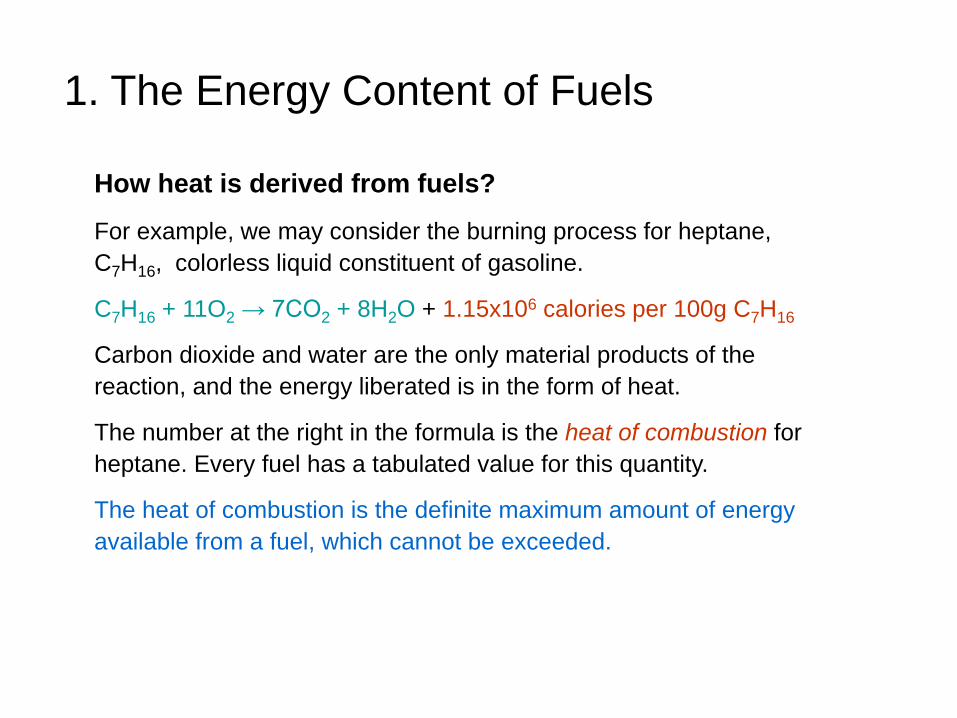
How heat is derived from fuels?
For example, we may consider the burning process for heptane,
C7H16, colorless liquid constituent of gasoline.
C7H16 + 11O2 → 7CO2 + 8H2O + 1.15x10⁶ calories per 100g C7H16
Carbon dioxide and water are the only material products of the
reaction, and the energy liberated is in the form of heat.
The number at the right in the formula is the heat of combustion for
heptane. Every fuel has a tabulated value for this quantity.
The heat of combustion is the definite maximum amount of energy
available from a fuel, which cannot be exceeded.
1. The Energy Content of Fuels

1. The Energy Content of Fuels
Two basic purposes to obtain fossil fuels: to provide direct heating and
lighting , and to power heat engines
Figure 3.1 The general pathways by which we utilize energy from fossil fuels

2. The Mechanical Equivalent of Heat
Which one is larger?
1 Btu = 778 foot-pound
You can lifting a one-pound weight 778 feet into the air with the
energy released by the burning of only one match.
Capture the heat energy of the fuel and turn it into mechanical energy.
The possibility of easing human labor by utilizing heat sources has
been the driving force behind a long history of development of what
we now call heat engines.
Unit for heat energy: 1Btu
(raise the temperature of one pound of water by one degree Fahrenheit)
Unit for mechanical energy: 1 foot-pound
(raise one pound of water one foot higher)

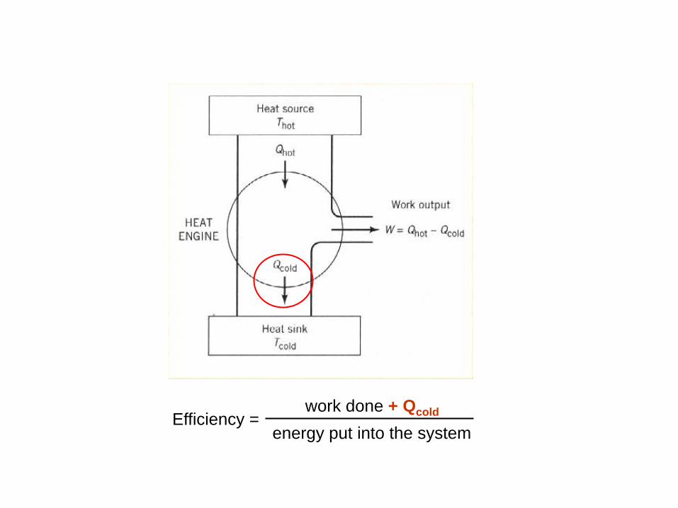
3. The Thermodynamic of Heat Engines
A heat engine is any device that can take energy from a warm source and
convert a fraction of this heat energy to mechanical energy.
Figure 3.2 A thermodynamic
diagram of a heat engine operating
between a heat source and heat sink
at a lower temperature. The work
output must equal the difference
between the heat energy extracted
from the source and that rejected to
the sink – the Principle of Energy
Conservation.

Not all of the heat energy taken from the source is being used to performed
useful work. Some fraction of the heat energy must always be rejected, at a
temperature cooler than that of the warm source, to the environment.
– The second law of thermodynamics
Kelvin statement:
It is impossible to convert heat completely into works in a cyclic process.
Clausius statement:
Heat generally cannot flow spontaneously from a material at lower
temperature to a material at higher temperature.
In a system, a process that occurs will tend to increase the total
entropy of the universe.
Efficiency = work done
energy put into the system < 100%

Efficiency = work done
energy put into the system
Efficiency = Qhot - Qcold
Qhot
= (1 - ) x 100% Qcold
Qhot
For an ideal engine, the ratio of two energy terms is identical to the ratio of
two temperature terms:
Qcold / Qhot = Tcold / Thot
where the temperatures are given on the absolute (Kelvin) scale.
Tcold Efficiency = (1 - ) x 100% Thot
It is remarkable that this efficiency (Carnot) depends only on the
temperatures of the two reservoirs between which the heat engine operates.
Carnot

A Carnot cycle taking place between a
hot reservoir at temperature TH and a
cold reservoir at temperature TC.
A generalized thermodynamic cycle
Tcold Efficiency = (1 - ) x 100% Thot

Example:
For a coal-fire electric power plant, Thot (the boiler temperature) would be 825 K,
and Tcold (the cooling tower) would be about 300 K. This leads to
Efficiency = (1 – 300 / 825) x 100% = (1 – 0.36) x 100% = 64%
• In this case, 36% of the heat energy from the energy of the fuel must be
wasted by rejecting it through the cooling tower to the surrounding
atmosphere.
• To make the efficiency as high as possible, it would be desirable to
increase Thot and decrease Tcold.
• The limit on Thot is imposed by the materials from which the boilers can be
constructed and the limit on Tcold is imposed by the availability in nature of
large sinks at sufficiently low temperature.
4. Generation of Electricity
In 1831, in London, Michael Faraday (1791-1876) discovered electromagnetic
induction – one of the greatest discoveries of all time.
Electromagnetic induction is the production of
voltage across a conductor situated in a changing
magnetic field or a conductor moving through a
stationary magnetic field.
The discovery made the generation and transmission of electricity possible,
and quickly lead to the invention of electric generators.
"This is all very interesting, but of what possible use are these toys?"
"I cannot say what use they may be, but I can confidently predict that
one day you will be able to tax them."
“ Of what use is a newborn baby? ”

Figure 3.4 An elementary
alternating current generator. A
loop of wire is forced to rotate in
a magnetic field. The induced
alternating current enters the
external circuit through contacts
(carbon brushes) that rub against
rotating metal rings, called slip
rings, attached to the coil. The
current generated, I, reverses in
direction as the coil rotates.
right hand rule & left hand rule
The current induced in the coils according to the Faraday law interacts
with the magnetic field to resist the motion of the coils through the field.
Therefore it takes energy from some external source to force the rotation.

Figure 3.3 A diagram of a
fuel-burning electric power
plant. Here a river provides
cooling water to the
condenser, but lake water or
a cooling tower could serve
the same purpose.
Most electric power plants have the rotating coils of the generator mechanically
connected to steam turbines or to water-driven hydroelectric turbines at large
dams. The main components of a typical electric power plant are shown in the
figure below.

Figure 3.5 Typical efficiency of an electric power plant for converting
chemical energy in the fuel into electric energy. The best new plants
now achieve nearly 40%.

5. Electric Power Transmission
• In order for electric energy to be useful to society, it must be
transported in some way from the power plants to factories or
residences.
• The first electric power system was developed by Thomas
Edison in New York in 1882, using direct current (DC).
• Alternating current (AC) offered greater flexibility in changing the
voltage at different points in the system with transformers.
• Raising the voltage continues to be the main way to reduce
transmission losses. (The loss is proportional to I2·R.)

Transmission and distribution losses in the USA were estimated at 7.2% in 1995 .
Diagram of an electrical system
The system of generating stations, substations and transmission lines is
called the electric power grid. Most of the electric power companies in
North America are integrated into a single power grid (3000 power plants,
200,000 miles of high-voltage transmission lines) for reasons of economy,
availability of backup power for emergencies, and ability to trade energy.
Wireless Transmission of Electricity?!
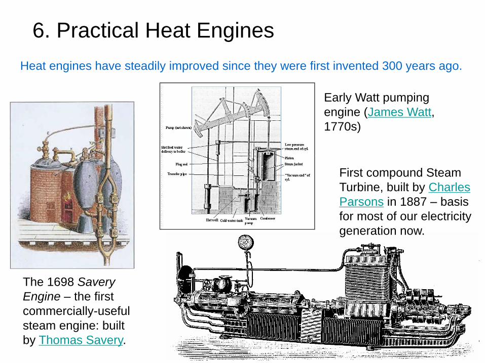
6. Practical Heat Engines
The 1698 Savery
Engine – the first
commercially-useful
steam engine: built
by Thomas Savery.
Early Watt pumping
engine (James Watt,
1770s)
Heat engines have steadily improved since they were first invented 300 years ago.
First compound Steam
Turbine, built by Charles
Parsons in 1887 – basis
for most of our electricity
generation now.

5.1 Steam Engines
A steam engine is a heat engine that performs mechanical work using
steam as its working fluid.
A locomotive powered by the force of
steam against pistons. The motion of
the pistons is coupled by connecting
rods directly to the drive wheels.
Principle of operation for a steam engine:
• When water is boiled to steam at
atmosphere pressure, its volume
expands about a thousand times.
• If the steam is confined, pressure
builds up and the steam tries to
expand with great force.
• This force can exerted against a
piston or it can work against the
blades of a turbine.
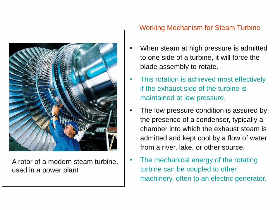
A rotor of a modern steam turbine,
used in a power plant
• When steam at high pressure is admitted
to one side of a turbine, it will force the
blade assembly to rotate.
• This rotation is achieved most effectively
if the exhaust side of the turbine is
maintained at low pressure.
• The low pressure condition is assured by
the presence of a condenser, typically a
chamber into which the exhaust steam is
admitted and kept cool by a flow of water
from a river, lake, or other source.
• The mechanical energy of the rotating
turbine can be coupled to other
machinery, often to an electric generator.
Working Mechanism for Steam Turbine

Steam engines belong to the broad class of external combustion heat
engine.
In engine of this type, the fuel is burned outside of the pressurized part of
the engine, at a relatively low temperature, at atmospheric pressure, and
in the presence of an abundance of air.
• Low emission of carbon monoxide and nitrogen oxides
• Emission of sulfur oxides and particulates depends on the fuel being
burned.

5.2 Gasoline Engines
Figure 3.9 The four strokes of a four
spark-ignited internal combustion engine:
(a) compression, (b) combustion,
(c) exhaust, and (d) fuel-air intake.
• The heat engine we now have in almost
all of our motor vehicles are internal
combustion engines.
• Gasoline is vaporized and mixed with air
to form a combustible mixture inside a
closed chamber.
• The mixture is compressed to about 6 to
10 times atmospheric pressure, then
ignited with an electric spark.
• On ignition, the fuel explodes, forming
hot gases (CO2, H2O, N2 …).
• The resulting hot gases (1000 oC)
expand with great force against the
piston, causing the crankshaft to rotate.
• About 25% of the chemical energy in the
fuel can be converted to mechanical
energy in a modern gasoline engine.

5.3 Diesel Engines
Figure 3.10 Cutaway drawing of a
diesel engine. Ignition is accomplished
by the high temperature produced by
the compressed of air.
The diesel engine is an internal combustion
engine similar to the gasoline engine.
Difference: Diesel engine does not use
electric spark ignition and it does not mix the
fuel and air before admitting them to the
combustion chamber.
• During the compression stroke, the diesel
combustion chamber contains only air.
• The pressure can reach as high as 15 atm and
the temperature of the compressed air has been
increased to the ignition point for a fuel-air mix.
• A short burst of fuel is injected into the chamber.
• The fuel mixes with the hot air and immediately
ignites without the help of an electric spark.

Advantage:
• The combustion temperature of diesel engine is higher than in a
spark-ignited gasoline engine, producing a higher thermodynamic
efficiency (> 30%).
• Diesel fuel has about 10% more Btu per gallon than gasoline.
• Low CO emission due to an excess of air (and oxygen) in the
combustion chamber
Disadvantage:
• Greater noisiness, initial cost, and weight
• Harder starting in cold weather
• Characteristic odor and visible smoke
• Greater emission of nitrogen oxides

5.4 Gas Turbines Diagram of a gas turbine engine
•A gas turbine, also called a combustion turbine, is a rotary engine that extracts
energy from a flow of combustion gas. It has an upstream compressor coupled to a
downstream turbine, and a combustion chamber in-between.
•Energy is added to the gas stream in the combustor, where air is mixed with fuel
and ignited. Combustion increases the temperature and volume of the gas flow. This
is directed through a nozzle over the turbine's blades, spinning the turbine and
powering the compressor.
•Energy is extracted in the form of shaft power, compressed air and thrust, in any
combination, and used to power aircraft, trains, ships, generators, and even tanks.
A continuously
running gasoline
engine
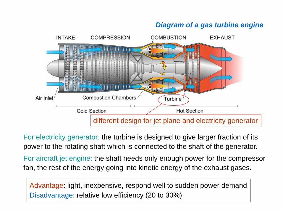
Diagram of a gas turbine engine
different design for jet plane and electricity generator
For electricity generator: the turbine is designed to give larger fraction of its
power to the rotating shaft which is connected to the shaft of the generator.
For aircraft jet engine: the shaft needs only enough power for the compressor
fan, the rest of the energy going into kinetic energy of the exhaust gases.
Advantage: light, inexpensive, respond well to sudden power demand
Disadvantage: relative low efficiency (20 to 30%)

7. Heat Pumps
Figure 3.11 A thermodynamic diagram of a heat pump.
A work input, W, is required to transfer an amount of
energy Qcold, out of a cold reservoir and a larger amount,
Qhot, into a hot reservoir. Because energy is conserved,
Qhot must equal W + Qcold.
The second law of thermodynamics
(Clausius statement)
Heat generally cannot flow spontaneously
from a material at lower temperature to a
material at higher temperature.
Can we remove energy from a cold
place and deliver it to a warmer place ?
Can we run the heat engine backward?
Heat pump: a device using
energy input in the form of
work to cause the transfer of
heat energy from the low T
to the another reservoir with
higher T.

The Coefficient of Performance (COP) is used to measure the effectiveness
of the heat pump.
COP = Qh/W = Qh/(Qh – Qc) = Th/(Th – Tc)
Calculate the ideal COP for an air-to-air heat pump used to maintain the
temperature of a house at 21oC when the outside temperature is -1oC.
Solution
Th = 21oC = 294 K
Tc = -1oC = 272 K
COP = Th/ (Th – Tc) = 294K/(294K – 272K) = 13.3
Thus, for each watt of power used to drive this heat pump, 13.3 watts are
delivered to the hot reservoir (the interior of the house), and 12.3 watts
are extracted from the cold reservoir (the outside the house). In practice,
the COP for such a situation would be much less favorable (in the range
of 2-6).
Example:

COP = Qh/W = Qh/(Qh – Qc) = Th/(Th – Tc)
The COP will diminish if the outside temperature drops. So electrically driven
air-to-air heat pumps are most useful in moderate climate (> -10oC). In
addition to the air-to-air heat pumps, it is common to use the ground at
several feet of depth, or surface water such as a river for the cold reservoir.

Figure 3.12 An electrically driven heat pump using
Freon as a working fluid.
Freon gas is
compressed by a
compressor to
raise its T and P.
The warm gas flows
through a heat
exchanger where it
is cooled by a flow
of room T air and
condensed to a
liquid, thus giving
up heat to the room.
On passage through
an expansion valve
into a region of
lower pressure, the
liquid expands into a
gas, becoming very
much colder.
The extremely cold gas
flows through a second
heat exchanger where it
is warmed to the outside
air T, thus extracting heat
from the outside air.
adiabatic
expansion

8. Cogeneration (废热发电,热电联产)
Cogeneration (also combined heat and power, CHP) is the use of a
heat engine to simultaneously generate both electricity and useful heat.
• The operation of a heat engine for any purpose is necessarily
accompanied by the rejection of heat energy, often in large amounts.
• The waste heat is generally dissipated into the atmosphere or an
adjacent body of water with possible negative environmental effects.
• A simple example of beneficial use of waste heat energy is using the
heater in an automobile.
• A cogeneration plant uses the rejected heat energy from electricity
generator for space heating in cities.
• A cogeneration plant is usually a small, decentralized electric generating
plants near the point of use, even right in the middle of a university
campus.
Efficiency = work done + Qcold
energy put into the system

Figure 3.13 A small cogeneration plant that uses the combustion of natural gas to
drive a gas turbine coupled to an electric generator. The hot exhaust gases boil water
to steam for use in space heating.
Efficiency of a new
coal-fired electric
power plant – 38%
Overall efficiency
of a cogeneration
can reach 70%.