energy harvesting from ambient vibrations by ...ethesis.nitrkl.ac.in/3738/1/final1.pdf1 energy...
TRANSCRIPT
1
Energy Harvesting from Ambient Vibrations by
Electromagnetic Transduction mechanism
A THESIS IN PARTIAL FULFILMENTS OF REQUIREMENTS FOR THE AWARD OF THE DEGREE OF
Bachelor of Technology
in
Electrical Engineering
By
Regan Kumar Sethi
(108EE053)
Department of Electrical Engineering
National Institute of Technology, Rourkela
MAY 2012

2
Energy Harvesting from Ambient Vibrations by
Electromagnetic Transduction mechanism
A THESIS IN PARTIAL FULFILMENTS OF REQUIREMENTS FOR THE AWARD OF THE DEGREE OF
Bachelor of Technology
in
Electrical Engineering
By
Regan Kumar Sethi
(108EE053)
Under the supervision of
PROF. G . Krishna
Department of Electrical Engineering
National Institute of Technology, Rourkela
MAY 2012
3
NATIONAL INSTITUTE OF TECHNOLOGY
ROURKELA
CERTIFICATE
This is to certify that the Project entitled “Energy Harvesting from Ambient Vibrations by
Electromagnetic Transduction mechanism” submitted by Regan Kumar Sethi(108EE053) in
partial fulfillment of the requirements for the award of Bachelor of Technology Degree in
Electrical Engineering at National Institute of Technology, Rourkela (Deemed University) and is
an authentic work carried out by him under my supervision and guidance.
To the best of my knowledge, the matter embodied in the thesis has not been submitted to any
other University/Institute for the award of any Degree or Diploma.
Date: 08/05/12 (Prof. G . Krishna)
Place: Rourkela Department of Electrical Engineering
NIT, Rourkela

4
Abstract
This report presents the detailed study of utilization of ambient vibration energy present in a
system by converting it into usable electrical energy. With the huge decrease in electrical
energy consumption in portable electronic devices the concept of harvesting electrical energy
from the renewable sources in the surroundings of the system arouses its great importance.
These low power micro electromechanical systems that can scavenge electrical energy from
their operating environment are very long lasting, less economical, need no maintenance, and
most importantly can be operated in inaccessible sites.
There are mainly three transduction mechanisms employed to extract electrical energy from
the vibration energy present in the surrounding of the system namely:-
Electromagnetic
Piezoelectric
Electrostatic
This paper is a study of electromagnetic transduction mechanism to harvest useful electrical
energy from the ambient vibrations.

5
Acknowledgement
I am extremely grateful to The Department of Electrical Engineering, for giving me the
opportunity to carry out this project, which is an integral fragment of the curriculum in B. Tech
program at the National Institute of Technology, Rourkela.
I would like to express my heartfelt gratitude and regards to my project guide, Dr. G. Krishna,
Department of Electrical Engineering, for being the corner stone of my project. It was his
incessant motivation and guidance during periods of doubts and uncertainties that has helped me
to carry on with this project.
I would like to thank Prof. B.D. Subudhi, Head of the Department, Electrical Engineering for
his guidance, support and direction. I am also obliged to the staff of Electrical Engineering
Department for aiding us during the course of our project. I offer my heartiest thanks to my dear
friends for their help in completing my project.
Last but not the least , I would love to acknowledge the contributions of my parents and family
members, for their constant and never ending motivation.

6
TABLE OF CONTENTS
ABSTRACT ....................................................................................................................... iv
ACKNOWLEDGMENTS .................................................................................................. v
CHAPTER I:
Introduction ..................................................................................................... 4
CHAPTER II:
Background and Literature Review ................................................................ 5
Basic Principle ................................................................................................ 5
Figures............................................................................................................. 7
CHAPTER III
Principle of Operation of Electromagnetic Transduction ............................. 11
Principle of Operation of Electrostatic Transduction ................................... 11
Principle of Operation of Piezoelectric Transduction ................................... 13
Methods of Modelling of Generator.............................................................14
CHAPTER IV
Results ........................................................................................................... 19
CHAPTER V
Conclusion .................................................................................................... 20
REFERENCES ................................................................................................................. 21

7
CHAPTER I
Introduction
The omnipresence of wireless systems in day today technologies because of its advantages over
the existing wired system such as flexibility, very easy to implement. The most significant
advantage is placement of wireless micro sensors in applications of condition based monitoring
at inaccessible locations to provide continuous monitoring without much expense and
inconvenience of wiring.
But these low power wireless sensor nodes need an alternative power source to the existing
batteries, so that the inconvenience of replacing them and the chemical disposal problem can be
sorted out.
Renewable power can be obtained by generating electricity from sources like solar energy,
thermal energy and kinetic energy available within the system’s environment. Though the other
sources can be alternatives but have some disadvantages like in the case of solar cells as it is of
no use in locations where there is no sunlight or dim light is present
Kinetic energy is typically present in the form of vibrations, random displacements or forces.
The review of this report is scavenging electrical energy from the vibrations, which can be
converted mainly by means of three transduction mechanisms namely
Electromagnetic
Piezoelectric
Electrostatic
The amount of electrical energy converted mainly depends upon
The quantity of vibrational energy available.
The efficiency of micro generator used
Power conversion electronics
The following pages are on the discussion of the three transduction mechanisms and the micro
generators that are used.
8
CHAPTER II
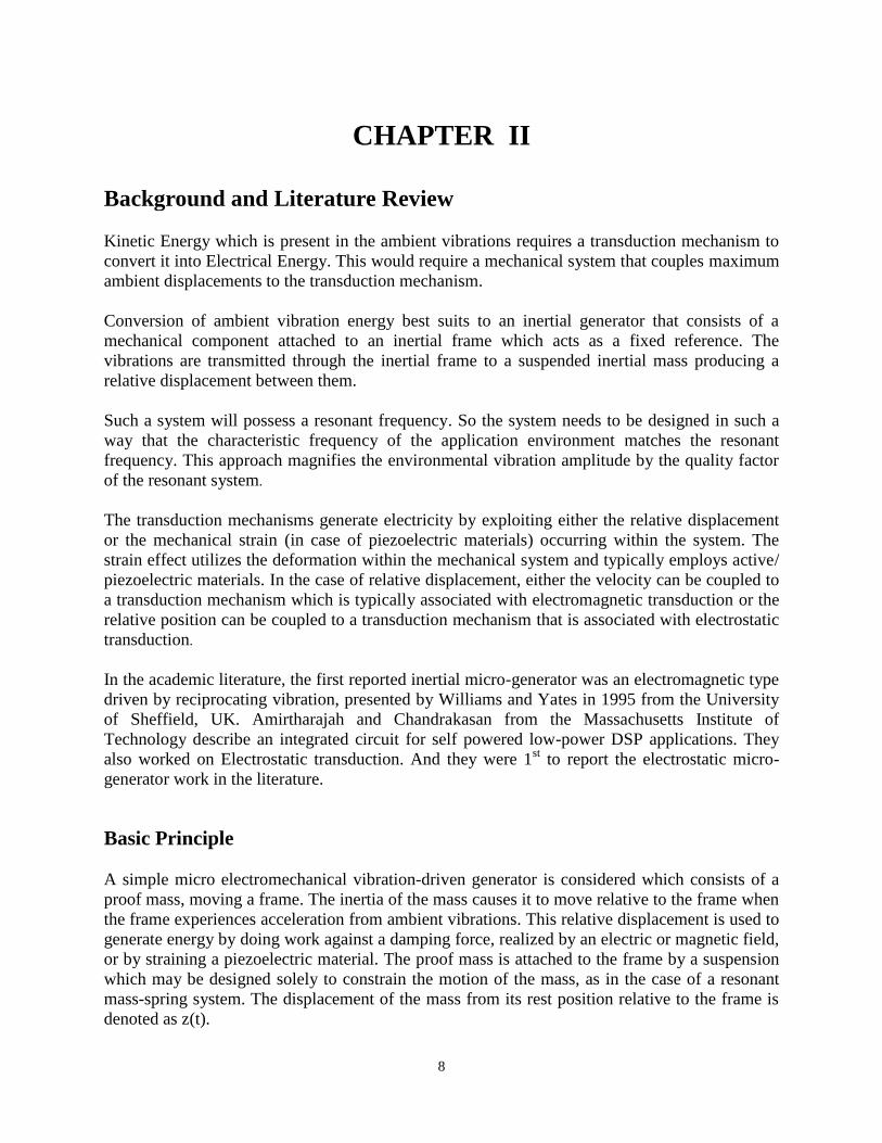
Background and Literature Review
Kinetic Energy which is present in the ambient vibrations requires a transduction mechanism to
convert it into Electrical Energy. This would require a mechanical system that couples maximum
ambient displacements to the transduction mechanism.
Conversion of ambient vibration energy best suits to an inertial generator that consists of a
mechanical component attached to an inertial frame which acts as a fixed reference. The
vibrations are transmitted through the inertial frame to a suspended inertial mass producing a
relative displacement between them.
Such a system will possess a resonant frequency. So the system needs to be designed in such a
way that the characteristic frequency of the application environment matches the resonant
frequency. This approach magnifies the environmental vibration amplitude by the quality factor
of the resonant system.
The transduction mechanisms generate electricity by exploiting either the relative displacement
or the mechanical strain (in case of piezoelectric materials) occurring within the system. The
strain effect utilizes the deformation within the mechanical system and typically employs active/
piezoelectric materials. In the case of relative displacement, either the velocity can be coupled to
a transduction mechanism which is typically associated with electromagnetic transduction or the
relative position can be coupled to a transduction mechanism that is associated with electrostatic
transduction.
In the academic literature, the first reported inertial micro-generator was an electromagnetic type
driven by reciprocating vibration, presented by Williams and Yates in 1995 from the University
of Sheffield, UK. Amirtharajah and Chandrakasan from the Massachusetts Institute of
Technology describe an integrated circuit for self powered low-power DSP applications. They
also worked on Electrostatic transduction. And they were 1st to report the electrostatic micro-
generator work in the literature.
Basic Principle
A simple micro electromechanical vibration-driven generator is considered which consists of a
proof mass, moving a frame. The inertia of the mass causes it to move relative to the frame when
the frame experiences acceleration from ambient vibrations. This relative displacement is used to
generate energy by doing work against a damping force, realized by an electric or magnetic field,
or by straining a piezoelectric material. The proof mass is attached to the frame by a suspension
which may be designed solely to constrain the motion of the mass, as in the case of a resonant
mass-spring system. The displacement of the mass from its rest position relative to the frame is
denoted as z(t).
9
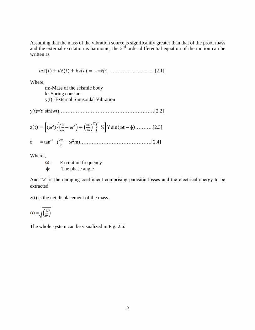
Assuming that the mass of the vibration source is significantly greater than that of the proof mass
and the external excitation is harmonic, the 2nd
order differential equation of the motion can be
written as
………………...........[2.1]
Where,
m:-Mass of the seismic body
k:-Spring constant
y(t):-External Sinusoidal Vibration
y(t)=Y sin(wt)…………………………………………………[2.2]
………..[2.3]
= tan-1
(
)…………………………………….[2.4]
Where ,
: Excitation frequency
: The phase angle
And “c” is the damping coefficient comprising parasitic losses and the electrical energy to be
extracted.
z(t) is the net displacement of the mass.
=
The whole system can be visualized in Fig. 2.6.

10
Figures
Fig 2.1: Electromagnetic Transduction
Fig 2.2: Electrostatic Transduction (Constant Charge Separation)
11
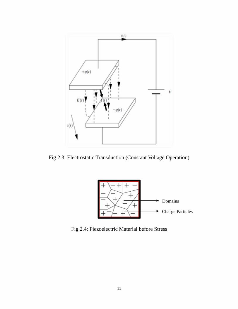
Fig 2.3: Electrostatic Transduction (Constant Voltage Operation)
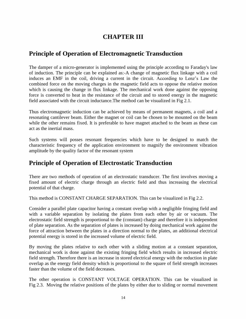
Fig 2.4: Piezoelectric Material before Stress
Domains
Charge Particles

12
Fig 2.5: Piezoelectric Material after Stress
Fig 2.6: General Model of Generator
Spring Constant
Proof Mass
Transducer
Charge Particles
Domains

13
Fig 2.7: General Model of Resonant Electromagnetic Generator
14
CHAPTER III
Principle of Operation of Electromagnetic Transduction
The damper of a micro-generator is implemented using the principle according to Faraday's law
of induction. The principle can be explained as:-A change of magnetic flux linkage with a coil
induces an EMF in the coil, driving a current in the circuit. According to Lenz’s Law the
combined force on the moving charges in the magnetic field acts to oppose the relative motion
which is causing the change in flux linkage. The mechanical work done against the opposing
force is converted to heat in the resistance of the circuit and to stored energy in the magnetic
field associated with the circuit inductance.The method can be visualized in Fig 2.1.
Thus electromagnetic induction can be achieved by means of permanent magnets, a coil and a
resonating cantilever beam. Either the magnet or coil can be chosen to be mounted on the beam
while the other remains fixed. It is preferable to have magnet attached to the beam as these can
act as the inertial mass.
Such systems will posses resonant frequencies which have to be designed to match the
characteristic frequency of the application environment to magnify the environment vibration
amplitude by the quality factor of the resonant system
Principle of Operation of Electrostatic Transduction
There are two methods of operation of an electrostatic transducer. The first involves moving a
fixed amount of electric charge through an electric field and thus increasing the electrical
potential of that charge.
This method is CONSTANT CHARGE SEPARATION. This can be visualized in Fig 2.2.
Consider a parallel plate capacitor having a constant overlap with a negligible fringing field and
with a variable separation by isolating the plates from each other by air or vacuum. The
electrostatic field strength is proportional to the (constant) charge and therefore it is independent
of plate separation. As the separation of plates is increased by doing mechanical work against the
force of attraction between the plates in a direction normal to the plates, an additional electrical
potential energy is stored in the increased volume of electric field.
By moving the plates relative to each other with a sliding motion at a constant separation,
mechanical work is done against the existing fringing field which results in increased electric
field strength. Therefore there is an increase in stored electrical energy with the reduction in plate
overlap as the energy field density which is proportional to the square of field strength increases
faster than the volume of the field decreases.
The other operation is CONSTANT VOLTAGE OPERATION. This can be visualized in
Fig 2.3. Moving the relative positions of the plates by either due to sliding or normal movement
15
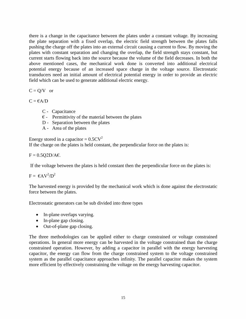
there is a change in the capacitance between the plates under a constant voltage. By increasing
the plate separation with a fixed overlap, the electric field strength between the plates falls
pushing the charge off the plates into an external circuit causing a current to flow. By moving the
plates with constant separation and changing the overlap, the field strength stays constant, but
current starts flowing back into the source because the volume of the field decreases. In both the
above mentioned cases, the mechanical work done is converted into additional electrical
potential energy because of an increased space charge in the voltage source. Electrostatic
transducers need an initial amount of electrical potential energy in order to provide an electric
field which can be used to generate additional electric energy.
C = Q/V or
C = €A/D
C - Capacitance
€ - Permittivity of the material between the plates
D - Separation between the plates
A - Area of the plates
Energy stored in a capacitor = 0.5CV2
If the charge on the plates is held constant, the perpendicular force on the plates is:
F = 0.5Q2D/A€.
If the voltage between the plates is held constant then the perpendicular force on the plates is:
F = €AV2/D
2
The harvested energy is provided by the mechanical work which is done against the electrostatic
force between the plates.
Electrostatic generators can be sub divided into three types
In-plane overlaps varying.
In-plane gap closing.
Out-of-plane gap closing.
The three methodologies can be applied either to charge constrained or voltage constrained
operations. In general more energy can be harvested in the voltage constrained than the charge
constrained operation. However, by adding a capacitor in parallel with the energy harvesting
capacitor, the energy can flow from the charge constrained system to the voltage constrained
system as the parallel capacitance approaches infinity. The parallel capacitor makes the system
more efficient by effectively constraining the voltage on the energy harvesting capacitor.

16
Table 3.1: Electrostatic force variation for the three configurations.
Structure Charge Constrained Voltage Constrained
In-plane overlap varying Fe ~ 1/x2 Fe constant
In-plane gap closing Fe ~ x Fe ~ 1/x2
Out-of-plane gap closing Fe constant Fe ~ 1/x
Principle of Operation of Piezoelectric Transduction
It is a phenomenon in which a strain in a material produces an electric field across that material.
The degree of polarisation is proportional to applied strain.
It was first discovered by J and P Curie.
When the material is strained, some of the mechanical work done on the device is stored as
elastic strain energy, and some in the electric field brought about by the space charge. The
material is unpolarised when unstrained (i.e. contains no average space charge across the
material), but becomes polarised when strained, so that a net electric field is generated. The
effect can be properly visualized in the below given figures. Fig 2.4 depicts the condition of
material before applying strain and Fig 2.5 after applying strain. Piezoelectric materials are
widely available in many forms including single crystal (e.g.quartz), piezoceramic (e.g. lead
zirconate titanate or PZT), thin film (e.g. sputtered zinc oxide), screen printable thick-films based
upon piezoceramic powders and polymeric materials such as polyvinylidenefluoride (PVDF).

17
Methods of Modelling a Generator
The generator can be modelled either by inertial mass system or direct force system. These are
properly described in the subsequent paragraphs.
The power generation for a given inertial generator is ultimately dependent upon the nature of
the damping force by which energy is extracted. There are mainly two different ways of sub-
dividing inertial generators namely;-
Resonant Generators
Parametric Generators
In the case of Resonant Generators the proof mass is suspended on a spring and resonant energy
exchange occurs between mass and spring. The highest possible power can be achieved by
tuning the resonant frequency of the mass-spring system to the frequency of the driving motion.
In the case of Parametric Generators suspension doesn’t employ any spring or the spring is
negligible, therefore no resonant energy transfer occurs.
Considering the Resonant Generators only, there are two types of resonant generators. One is
damped by a force which is proportional to velocity called the velocity-damped resonant-
generator (VDRG), and the other is damped by a constant force called the Coulomb-damped
resonant-generator (CDRG), and also one nonlinear generator, the Coulomb-force parametric-
generator (CFPG). All three can be implemented in MEMS, using electromagnetic (for the
VDRG) or electrostatics (for the other two).
Now let me consider a Velocity Damped Resonant Generator similar to the general model of
generator as shown in the Fig 2.7.The generator is to operate in modes in which the proof mass
does not strike the end limits because in the modes of operation in which the proof mass reaches
the limits results in collision leading to dissipation of energy reducing the efficiency of the
device. The forces acting on the proof mass are inertial, spring, damping force and gravity. The
optical power is derived as a function of Zl/Y0 and W/Wn and can be normalised to Y02w
3m.This
normalisation is used because it has dimensions of power and has a fraction of maximum kinetic
energy of the mass that is dissipated in the damper each cycle.
The differential equation for the motion of mass m, relative to the frame is;-
Taking Laplace Transformation of the above equation and dividing it with m we get;-
Where,
18
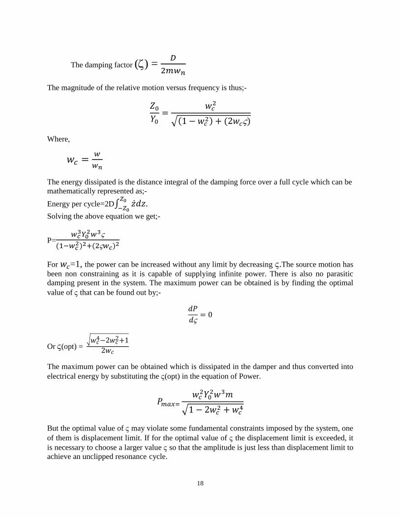
The damping factor () =
The magnitude of the relative motion versus frequency is thus;-
Where,
The energy dissipated is the distance integral of the damping force over a full cycle which can be
mathematically represented as;-
Energy per cycle=2D
.
Solving the above equation we get;-
P=
For =1, the power can be increased without any limit by decreasing .The source motion has
been non constraining as it is capable of supplying infinite power. There is also no parasitic
damping present in the system. The maximum power can be obtained is by finding the optimal
value of that can be found out by;-
Or (opt) =
The maximum power can be obtained which is dissipated in the damper and thus converted into
electrical energy by substituting the (opt) in the equation of Power.
But the optimal value of may violate some fundamental constraints imposed by the system, one
of them is displacement limit. If for the optimal value of the displacement limit is exceeded, it
is necessary to choose a larger value so that the amplitude is just less than displacement limit to
achieve an unclipped resonance cycle.

19
The electromagnetic transduction implementation is best carried out in velocity damped
resonance generator which consists of a moving magnet producing a flux that links with a
stationary coil of inductance (L) and resistance (R). According to Faraday’s law of induction a
voltage is induced in the coil due to the varying magnetic flux linkage caused by the movement
of the magnet given by:-
(t)N A
Where,
N: Number of turns
: Gradient of flux =
A: Coil Area
This causes a resultant current to flow which according to Lenz’s law opposes the relative
motion of the magnet and the coil. According to the principle of virtual work the rate of
mechanical work being done in moving the coil is always equal to the electrical power generated
by the EMF. The force on the coil is given by:-
f(t). (t) = i(t).e(t)
or f(t) = i(t)NA
In the Laplace domain the above equation transforms to:-
F(s) = I(s)A
I(s) =
E(s) = sZ(s)NA
Substituting the values of I(s) and E(s) we get:-
F(s) =
The differential equation for the above system is same as that in the previous mentioned equation
2.1, with the f(t) taking the place of d . Talking Laplace Transform of the equation and
substituting the value of F(s) we get:-
The system would turn out to be a perfect velocity damper at resonance (w= ) as “wL” term is
very small in comparison to R. So neglecting the L terms and finding the modulus of the
displacement transfer function by calculating the magnitude of the above function we get:-
20
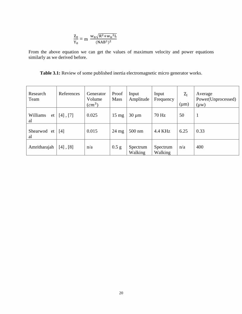
= m
From the above equation we can get the values of maximum velocity and power equations
similarly as we derived before.
Table 3.1: Review of some published inertia electromagnetic micro generator works.
Research
Team
References Generator
Volume
( )
Proof
Mass
Input
Amplitude
Input
Frequency
(µm)
Average
Power(Unprocessed)
(µw)
Williams et
al
[4] , [7] 0.025 15 mg 30 µm 70 Hz 50 1
Shearwod et
al
[4] 0.015 24 mg 500 nm 4.4 KHz 6.25 0.33
Amritharajah [4] , [8] n/a 0.5 g Spectrum
Walking
Spectrum
Walking
n/a 400

21
Fig 2.1: Bode Plot of average power output at varying resonant frequency with
constant damping ratio ().
Fig 2.1: Bode Plot of average power output for varying resonant frequency with
varying damping ratio ()

22
MATLAB Code for Bode Plot of average power output at varying resonant frequency with
constant damping ratio ().
function [ ] = bodeplot( )
clc;
m = 1;
p = zeros(1,8);
j=0.1;
ws = 1.6;
for wn=0.8:0.8:2.4
for w=1:1:150
p(w)= ((m*j*0.1)*((w/(50*wn))^2)*((w/50)^3))/(((1-
(w/(50*wn))^2)^2)+(2*j*(w/(50*wn)))^2);
end
w = [0.02:0.02:3.0];
disp(w);
disp(p);
hold on
plot(w,p);
end
plot(ws,w);
hold off
end

23
MATLAB Code for Bode Plot of average power output for varying resonant frequency with
varying damping ratio ().
function [ ] = bodeplots( )
clc;
wn = 0.8;
m = 1;
p = zeros(1,8);
ws = [0.02:0.02:1.6];
for j=0.1:0.1:0.3
for w=1:1:80
p(w)= ((m*j*0.1)*((w/(50*wn))^2)*((w/50)^3))/(((1-
(w/(50*wn))^2)^2)+(2*j*(w/(50*wn)))^2);
end
hold on
plot(ws,p);
end
j=1;
for w=1:1:80
p(w)= ((m*j*0.1)*((w/(50*wn))^2)*((w/50)^3))/(((1-
(w/(50*wn))^2)^2)+(2*j*(w/(50*wn)))^2);
end
plot(ws,p);
hold off
end

24
CHAPTER IV
Results
All the three transduction mechanisms are studied in details. And suitable generators would be
modeled by using any one of the three transduction mechanism which we derived
mathematically. All the mechanisms need different ways to model the generator keeping in mind
their characteristics to derive maximum electrical energy. The energy harvested from the
vibrations are then suitably used using a process that can be visualized in the figure below
Fig 4
The voltage output is suitable increased by using a transformer of required ratio.
25
CHAPTER V
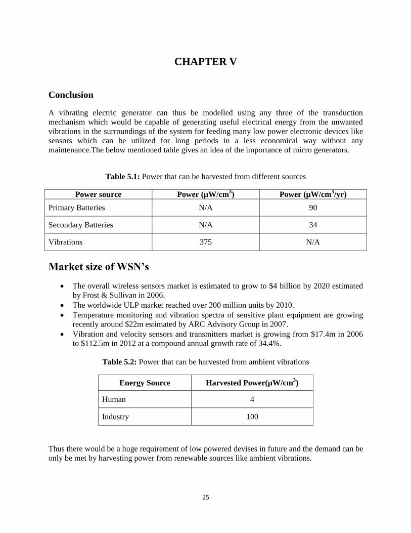
Conclusion
A vibrating electric generator can thus be modelled using any three of the transduction
mechanism which would be capable of generating useful electrical energy from the unwanted
vibrations in the surroundings of the system for feeding many low power electronic devices like
sensors which can be utilized for long periods in a less economical way without any
maintenance.The below mentioned table gives an idea of the importance of micro generators.
Table 5.1: Power that can be harvested from different sources
Power source Power (µW/cm3) Power (µW/cm
3/yr)
Primary Batteries N/A 90
Secondary Batteries N/A 34
Vibrations 375 N/A
Market size of WSN’s
The overall wireless sensors market is estimated to grow to $4 billion by 2020 estimated
by Frost & Sullivan in 2006.
The worldwide ULP market reached over 200 million units by 2010.
Temperature monitoring and vibration spectra of sensitive plant equipment are growing
recently around $22m estimated by ARC Advisory Group in 2007.
Vibration and velocity sensors and transmitters market is growing from $17.4m in 2006
to $112.5m in 2012 at a compound annual growth rate of 34.4%.
Table 5.2: Power that can be harvested from ambient vibrations
Energy Source Harvested Power(µW/cm3)
Human 4
Industry 100
Thus there would be a huge requirement of low powered devises in future and the demand can be
only be met by harvesting power from renewable sources like ambient vibrations.
26
REFERENCES
[1] Williams C.B., Pavic A., Crouch R. S., Woods R.C., Feasibility study of vibrational
electric generator for bridge vibration sensors. IMAC-XVI Proceedings, 1997.
[2] Hadas Z.,Jan Z.,Singule V,Ondrusek C., Design of Energy harvesting Generator base on
rapid prototyping parts. 2008 13th International Power Electronics and Motion Control
Conference (EPE-PEMC 2008).
[3] Stephen N.,G., On energy harvesting from ambient vibrations. Journal of Sound and
Vibration 393,2006.
[4] Mitcheson P.D. Analysis and optimization of energy harvesting micro generator systems,
2005.
[5] Beeby S.P., Tudor M.J., White N.M., Energy harvesting vibration sources for
Microsystems applications, 26th
October 2006. Meas. Sci. Technol. 17 (2006) R175–
R195.
[6] Lobontiu Nicolae, Garcia Ephrahim, Mechanics Of Microelectromechanical Systems,
New York, London, Boston, Dordrecmt, Moscow, Kulwer Academic Publishers, 2005.
[7] Williams C.B and Yates R.B, .Analysis of a Micro-Electric Generator for Microsystems,.
in The 8th International Conference on Solid-State Sensors and Actuators, Eurosensors
IX and Transducers '95.
[8] Amirtharajah R, .Design of Low-Power VLSI Systems Powered by Ambient Vibration,.
Ph.D. dissertation, Massachusetts Institude of Technology, June 1999.