energy management and control strategy of dc source and
TRANSCRIPT

International Journal of Energy and Power Engineering 2018; 7(1-1): 9-18 http://www.sciencepublishinggroup.com/j/ijepe doi: 10.11648/j.ijepe.s.2018070101.12 ISSN: 2326-957X (Print); ISSN: 2326-960X (Online)
Energy Management and Control Strategy of DC Source and Microturbine Generation System by Using PQ Controller and Droop Control in Islanded Mode
Nduwamungu Aphrodis
School of Electrical Engineering and Automation, Tianjin Polytechnic University, Microgrids Research Programme, Tianjin, China
Email address: [email protected]
To cite this article: Nduwamungu Aphrodis. Energy Management and Control Strategy of DC Source and Microturbine Generation System by Using PQ
Controller and Droop Control in Islanded Mode. International Journal of Energy and Power Engineering. Special Issue: Green Hybrid
Systems for Power Generation in Remote Zones Non-Connected to Grid. Vol. 7, No. 1-1, 2018, pp. 9-18.
doi: 10.11648/j.ijepe.s.2018070101.12
Received: September 26, 2017; Accepted: December 3, 2017; Published: January 4, 2018
Abstract: The requirements of power quality, public environment policy and expansion power demand are providing better
opportunity to the microturbine (MTG) to be best microsources for improving the system stability, reliability and power
quality. This paper presents modelling and control strategy of MTG system by using PQ controller and Droop control in
islanded mode. The model developed in this work includes the individual components of prime mover like, compressor, heat
exchanger, burner and turbine. The model of MTG system consists of microturbine, permanent magnet synchronous machine
and power electronics interfacing circuit for generation and conversation from AC/DC/AC respectively and design of PQ
controller including droop control with current and voltage loop and power loop. The simulations are carried out in islanded
mode of the system to observe its behavior when supplying customer under variable load. It also incorporates modeling and
simulation of microturbine with speed control, temperature control, and heat control, frequency control, voltage control and
designing of filters in order to eradicate harmonics and suppress all kind of disturbance exist in network during transmission
and distribution. The load following characteristics is observed and validated for this MTG-synchronous generator model in
Matlab-Simulink environment with power system block.
Keywords: Distributed Generation (DG), Microturbine Generation System, DC source, PQ Controller and Droop Control
1. Introduction
In nowadays microturbines are marketable and
commercialized as a distributed generation (DG) technology
like other microsources such as photovoltaic arrays, fuel
cells, wind turbines and direct current source (DC),
microturbine and photovoltaic arrays are generally best
microsource suited to compensate and improve power system
stability, reliability and play a key role in heat production and
the same time supply power to the utility grid [5]. Therefore
microturbine is suitable for small applications and are
designed to produce electricity for onsite energy needs and
for end users in close proximity to the generation site. Many
microturbine, their output are varies between 30 kilowatt
(kW) up to 250 megawatts (MW) [6-7]. DG allows the rural
electrification, industry to reduce the traditional cost of
service with a specific controller such as PQ controller and
droop control in order to be integrated in electrical network
with static transfer switch (STS). Distributed energy
resources are composed by varieties of small modular
distributed generation (DG) technologies that can be
combined with energy management system like battery
charging and discharging algorithm and storage systems.
Distributed energy resources allows renewable energies
utilization and more efficient utilization of waste heat in
combined heat and power (CHP) applications and lowering
emissions in order to sustainable an environment [3-4].
Normally MTG has the following specifications:
1. Relatively small in size compared with other
distributed energy resources.

10 Nduwamungu Aphrodis: Energy Management and Control Strategy of DC Source and Microturbine Generation System by Using PQ Controller and Droop Control in Islanded Mode
2. It has higher efficiency, fuel to electricity conversion
which can vary 25% to 30%. In whatever way, if the
waste recovery is used, combined heat and electric
power could achieve energy efficiency levels greater
than 80%.
3. Environmental superiority, NOx emissions lower than7
parts per million for natural gas machines in practical
operating ranges.
4. Durable, designed for 11,000 hours of operation
between major overhauls and a service life of at least
45, 000 hours.
5. Economical, system costs lower than $500 per KW,
costs of electricity that are competitive with alternative
including grid-connected power for market applications
[3].
6. Fuel flexibility, capable of using alternative/optional
fuels including natural gas, diesel, ethanol, landfill gas
and other bio-mass derived liquids and gases.
Generally there are two types of microturbines which are
namely recuperated and unrecuperated microturbine and
those type are completely different according to the table
below
Table 1. Comparison between types of Microturbine [12].
Unrecuperated Recuperated
Compressed air is mixed with fuel and burned under constant pressure
conditions.
A sheet metal heat exchanger (recuperator) recovers temperature of the air
stream supplied to the combustor.
Efficiency 15%. Efficiency 20~30%.
How a microturbine works?
Figure 1. Working principle of microturbine [13].
2. Microturbine Generation System and Control Strategies
Figure 2 is composed by two microsources namely DC source controlled by PQ controller in order to control frequency and
voltage meanwhile second microsource which is microturbine is controlled by droop control in order to provide frequency and
voltage to the PQ controller because PQ controller can’t work alone. Normally there are more than four type of PQ controller
but i decided to use the following type of PQ controller and it is drawn in figure 4 [8].

International Journal of Energy and Power Engineering 2018; 7(1-1): 9-18 11
Figure 2. Schematic diagram of microturbine generation system and its control strategies.
Even though voltage and frequency are depending on variation of loads so that in order to maintain frequency and voltage in
range we should have some limitation based on the droop control and schematized in figure 3 [8].
Figure 3. Schematic diagram of droop control.
Figure 4. Schematic diagram of PQ controller.

12 Nduwamungu Aphrodis: Energy Management and Control Strategy of DC Source and Microturbine Generation System by Using PQ Controller and Droop Control in Islanded Mode
Figure 4 presents the PQ controller which is frequently
used for maintaining the magnitude and frequency of voltage
when the load continue to fluctuates as illustrated in figure 4.
The PQ controller strategy provides current reference signal
by decoupling the active and reactive power with the
regulation of PI controller. A current error signal formed by
the reference current and the inverter current will provide
PWM signals to the inverter by the effects of PI controller.
An ideal SPWM model is utilized to satisfy the inverter’s
requirement, and a three-phase phase locked loop (PLL) is
adopted in following the voltage angles of the grid, which
supports frequency for the control system.
3. Dynamic Model of Microturbine
Generation System
3.1. Modelling and Control Strategy of Microturbine
Figure 2 represents overall model of microgrid with two
microsources but for microturbine is a model of single shaft
microturbine which is composed by a speed control which is
approximately 96000 rpm, acceleration control, temperature
control, fuel flow control and compressor control [9-10].
Figure 5. Schematic diagram of an internal control of microturbine [11].
3.1.1. Speed and Acceleration Control Strategy
The differential control mode is normally called droop
control meanwhile it has been considered as the primary
mains of speed control for microturbine under load variation
with different conditions. A droop governor is proportional to
the speed controller where the input is a speed error formed
by a reference speed and the microturbine generator system
rotor speed while the output is proportional to the speed
error. In this paper, a lead lag transfer function has been used
to represent the speed controller, as shown in Figure 6.
Figure 6. Diagram of the speed controller for the micro-turbine [16].
K=25, =0.4, =1.0, Z=10;
3.1.2. Fuel Control System
The main parts of fuel system are fuel valve and actuator.
The fuel come out from the fuel system results from the
inertia of the fuel system actuator and of the valve positioner
and its equations are expressed below. The valve positioner
transfer function is [14]:
(1)
In addition, the fuel system actuator transfer function can
be expressed as [14]:
(2)
In the equations (1) and (2), are the valve
positioner (fuel system actuator) gain, , are called the
valve positioner and fuel system actuator time constants,

International Journal of Energy and Power Engineering 2018; 7(1-1): 9-18 13
whereas c is a constant, moreover and are the input
and outputs of the valve positioner eventually is the fuel
required signal in p. u. The output of the LVG, , represents the least quantity of fuel needed for that particular operating point and is an input to the fuel system. Another input to the fuel system which is the per-unit turbine speed N. The per-
unit value for is directly correspond to the per-unit value
of the mechanical power on turbine at steady-state. The fuel
flow control as a function of is shown in Figure 7. The
value of is from the gainK K 1 " K#$, although that output is delayed and offset by minimum value of fuel flow # that is required to ensure the continuous combustion
process. In addition, # is the minimum amount of fuel required at no load available and at rated speed [15]:
Figure 7. Control block diagram of the fuel system.
The figure 7 the fuel system parameters are specified accordingly this:
K% 1, T' 0.05, C 1, K 0.33, K# 0.23, K. 1, T 0, T. 0.04
3.1.3. Compressor Turbine System
The compressor-turbine is a linear and non-dynamic device.
It is also the vital part of the microturbine. The annotation
block diagram of compressor-turbine system is shown in figure
8 whereby the torque and the exhaust temperature
characteristics has shown in the figure 8 in addition for single
shaft gas turbine are essentially linear with respect to fuel flow
and turbine speed. These characteristics are given and
described by the following equations [17], [18].
T K00% W. " o. 23$ 3 o. 5 1 " N$5Nm7 (3)
And the exhaust system function is given by this equation
[17], [18]:
8 9 " 700;1 " < 3 550 1 " =$> (4)
9 0.01 , ? =0.04, ? 0.2, @@ 0.2. KHHV is the coefficient that depend upon the enthalpy or higher heating value of the gas in the combustion chamber and TR is the reference temperature. In the torque equation, the KHHV and the constant 0.23 cater for the typical power/fuel characteristic, which varies linearly and gradually from zero power at 23% fuel flow rate to the rated output at 100% fuel
flow rate. This system, input is fuel A demand signal in per unit and outputs are the per unit turbine torque and exhaust temperature (°F).
Figure 8. Diagram of compressor turbine package of microturbine [16], [14].
3.1.4. Temperature Control System
The main role of temperature control is to restrict turbine
output power at a predetermined firing temperature,
independent of variation in environmental temperature or
fuel characteristics. The exhaust temperature which is
calculated by means of a series of thermocouple which
incorporated inside and is compared with a reference value,
and the error between them is considered as temperature
control signal. The temperature controller works by limiting
the fuel input to limit the exhaust temperature of a
microturbine in order to play a protective role on the turbine
parts, as shown in Figure 9 [1].

14 Nduwamungu Aphrodis: Energy Management and Control Strategy of DC Source and Microturbine Generation System by Using PQ Controller and Droop Control in Islanded Mode
Figure 9. Temperature control block.
KB 0.8, KD 0.2, T 15, TB 2.5, TD 3.3, TE 450>, TF 950>. 3.1.5. Permanent Magnet Synchronous Machine
As aforementioned, the single shaft microturbine produces electrical power through a high speed permanent magnet synchronous generator directly driven by the compressor turbine shaft. In this paper the mathematical model of the PMSG is provided in MATLAB/SIMULINK software
package and some assumptions have made where LIJ LKJ and interior magnet machine are negligible and dqo
axis equation can be written as follows [16], [18], [5], and [19]:
L MLN L " OΨQL 3 RST U (5)
QL MLNQL 3 OΨ LV 3 OΨ 3 RT U (6)
The electromagnetic torque produced in the machine air
gap is based on conversion of three phase to two phase where
we take this ration of 3/2 and the torque is given by:
∗ X Y LNQL " YQLN L$ (7)
And the mechanical torque is written as follows [18], [5],
and [19]:
m e
dT J T R
dt
ω ωΩ= + + (8)
The signs of torques have different meaning according the
sign the reason why if the generated torque and shaft
torque LZ[U are positive exclusively for motor operation
and negative for generator operation only [2]. Therefore, the
equivalent circuits of permanent magnet synchronous
machine is based on the equations (5), (6) and (7) so it can be
represented by as follows [2]:
Figure 10. Equivalent circuits of permanent magnet synchronous machine.
3.2 Diagram of Voltage and Current Loop Controller
In order to supply power quality, voltage and current
should be controlled dynamically with highest precision.
Technically there are many control strategies which are
ubiquitous and are named current and voltage loop controller,
therefore, They have different advantages which are listed are
here:
1. Fast transient response.
2. Automatic dynamic limitation.
3. Best achievement of current sharing between parallel
inverters etc. However, the equations of voltage and
current loops are written as follows [15]:
International Journal of Energy and Power Engineering 2018; 7(1-1): 9-18 15
\ eI ;k_ 3 `ab c iI∗ " iI$ " ωLiK 3 VIeK gK_ 3 `hi . $;iK∗ "iK< " ωLiI 3 VK (9) \iI gK_ 3 `hi c VI∗ " VI$ " ωCVK 3 ijIiK gK_ 3 `hi c ;VK∗ " VK< 3 ωCVI 3 ijK (10)
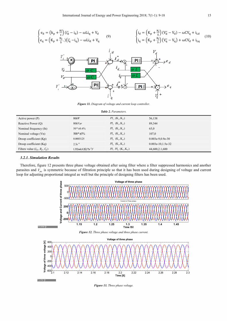
Figure 11. Diagram of voltage and current loop controller.
Table 2. Parameters.
Active power (P) 80kW 1PI , (K ,K )I P 56,138
Reactive Power (Q) 80kVar 2PI (K ,K )I P 89,344
Nominal frequency (fn) 50* 0.4%± 3PI (K ,K )I P 65,0
Nominal voltage (Vn) 500* 5%± 4PI (K ,K )I P 107,0
Droop coefficient (Kp) 0.0003125 5PI (K ,K )I P 0.003e-9,0.9e-30
Droop coefficient (Kq) 62.5e− 6PI (K ,K )I P
0.003e-10,1.5e-32
Filters value (k, M, l) 41.352 ,0.2 ,75mh e F−Ω 7PI 8PI (K ,K )I P
44,600,2.1,600
3.2.1. Simulation Results
Therefore, figure 12 presents three phase voltage obtained after using filter where a filter suppressed harmonics and another
parasites and abcV is symmetric because of filtration principle so that it has been used during designing of voltage and current
loop for adjusting proportional integral as well but the principle of designing filters has been used.
Figure 12. Three phase voltage and three phase current.
Figure 13. Three phase voltage.
-500
0
500
Voltage of three phase
1.15 1.2 1.25 1.3 1.35 1.4 1.45
-200
0
200
Time [S]
Vo
ltag
e a
nd
Cu
rren
t o
f th
ree p
hase
Current of Three phase
2.1 2.12 2.14 2.16 2.18 2.2 2.22 2.24 2.26 2.28 2.3-600
-400
-200
0
200
400
600
Time [S]
Vo
ltag
e o
f th
ree v
olt
ag
e [
V]
Voltage of three phase

16 Nduwamungu Aphrodis: Energy Management and Control Strategy of DC Source and Microturbine Generation System by Using PQ Controller and Droop Control in Islanded Mode
Figure 13 represents voltage of three phase obtained after using filteration mechanism where a filter eliminated all
harmonics and another kind of parasite. Filter has been used for making three phase voltage to be so sysmetric.
Figure 14. Reactive power produced by microturbine.
This active power produced by microturbine at 0.5s there is a load connected on network meanwhile at 1.5 s that load has
been disconnected and active power decreased until it reached an initial value.
Figure 15. Frequency of network in hertz.
Schematically frequency depends on variation of active power where the changes of active power automatically affect
frequency. In order to achieve the effectiveness and competitiveness of PQ controller in islanded mode the connection and
disconnection of loads on network should be handled carefully for avoiding some network problems such as blackout and
brownout.
Figure 16. Reactive power from microturbine.
The reactive power increased at 1s because of a load connected whereas at 2s that load has been disconnected and reactive power decreased but in main network inducted load is connected since the starting of simulation. Therefore the variation of reactive power has been provoked some impact on voltage due to the principal of PQ controller that is the reason why figure 3
presents the constraints of voltage and frequency. So that voltage and frequency are restricted at * 5%nV ± and * 0.4%nf ±
where they have been implementation due to the results.
0 0.5 1 1.5 2 2.5 3 3.5 4 4.5 50
2
4
6
8
10x 10
4
Time [s]
Acti
ve P
ow
er
[kW
]
Active Power
0 0.5 1 1.5 2 2.5 3 3.5 4 4.5 5
49.8
49.9
50
50.1
50.2
Time[S]
Fre
qu
en
cy [
Hz]
Frequency
0 0.5 1 1.5 2 2.5 3 3.5 4 4.5 5
0
2
4
6
8
x 104
Time [s]
Reacti
ve P
ow
er
[kV
ar]
Reactive Power
International Journal of Energy and Power Engineering 2018; 7(1-1): 9-18 17
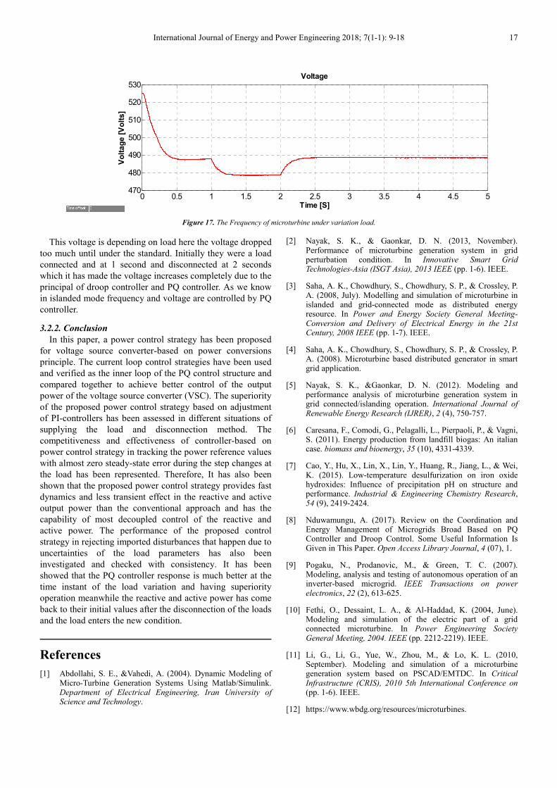
Figure 17. The Frequency of microturbine under variation load.
This voltage is depending on load here the voltage dropped
too much until under the standard. Initially they were a load
connected and at 1 second and disconnected at 2 seconds
which it has made the voltage increases completely due to the
principal of droop controller and PQ controller. As we know
in islanded mode frequency and voltage are controlled by PQ
controller.
3.2.2. Conclusion
In this paper, a power control strategy has been proposed
for voltage source converter-based on power conversions
principle. The current loop control strategies have been used
and verified as the inner loop of the PQ control structure and
compared together to achieve better control of the output
power of the voltage source converter (VSC). The superiority
of the proposed power control strategy based on adjustment
of PI-controllers has been assessed in different situations of
supplying the load and disconnection method. The
competitiveness and effectiveness of controller-based on
power control strategy in tracking the power reference values
with almost zero steady-state error during the step changes at
the load has been represented. Therefore, It has also been
shown that the proposed power control strategy provides fast
dynamics and less transient effect in the reactive and active
output power than the conventional approach and has the
capability of most decoupled control of the reactive and
active power. The performance of the proposed control
strategy in rejecting imported disturbances that happen due to
uncertainties of the load parameters has also been
investigated and checked with consistency. It has been
showed that the PQ controller response is much better at the
time instant of the load variation and having superiority
operation meanwhile the reactive and active power has come
back to their initial values after the disconnection of the loads
and the load enters the new condition.
References
[1] Abdollahi, S. E., &Vahedi, A. (2004). Dynamic Modeling of Micro-Turbine Generation Systems Using Matlab/Simulink. Department of Electrical Engineering, Iran University of Science and Technology.
[2] Nayak, S. K., & Gaonkar, D. N. (2013, November). Performance of microturbine generation system in grid perturbation condition. In Innovative Smart Grid Technologies-Asia (ISGT Asia), 2013 IEEE (pp. 1-6). IEEE.
[3] Saha, A. K., Chowdhury, S., Chowdhury, S. P., & Crossley, P. A. (2008, July). Modelling and simulation of microturbine in islanded and grid-connected mode as distributed energy resource. In Power and Energy Society General Meeting-Conversion and Delivery of Electrical Energy in the 21st Century, 2008 IEEE (pp. 1-7). IEEE.
[4] Saha, A. K., Chowdhury, S., Chowdhury, S. P., & Crossley, P. A. (2008). Microturbine based distributed generator in smart grid application.
[5] Nayak, S. K., &Gaonkar, D. N. (2012). Modeling and performance analysis of microturbine generation system in grid connected/islanding operation. International Journal of Renewable Energy Research (IJRER), 2 (4), 750-757.
[6] Caresana, F., Comodi, G., Pelagalli, L., Pierpaoli, P., & Vagni, S. (2011). Energy production from landfill biogas: An italian case. biomass and bioenergy, 35 (10), 4331-4339.
[7] Cao, Y., Hu, X., Lin, X., Lin, Y., Huang, R., Jiang, L., & Wei, K. (2015). Low-temperature desulfurization on iron oxide hydroxides: Influence of precipitation pH on structure and performance. Industrial & Engineering Chemistry Research, 54 (9), 2419-2424.
[8] Nduwamungu, A. (2017). Review on the Coordination and Energy Management of Microgrids Broad Based on PQ Controller and Droop Control. Some Useful Information Is Given in This Paper. Open Access Library Journal, 4 (07), 1.
[9] Pogaku, N., Prodanovic, M., & Green, T. C. (2007). Modeling, analysis and testing of autonomous operation of an inverter-based microgrid. IEEE Transactions on power electronics, 22 (2), 613-625.
[10] Fethi, O., Dessaint, L. A., & Al-Haddad, K. (2004, June). Modeling and simulation of the electric part of a grid connected microturbine. In Power Engineering Society General Meeting, 2004. IEEE (pp. 2212-2219). IEEE.
[11] Li, G., Li, G., Yue, W., Zhou, M., & Lo, K. L. (2010, September). Modeling and simulation of a microturbine generation system based on PSCAD/EMTDC. In Critical Infrastructure (CRIS), 2010 5th International Conference on (pp. 1-6). IEEE.
[12] https://www.wbdg.org/resources/microturbines.
0 0.5 1 1.5 2 2.5 3 3.5 4 4.5 5470
480
490
500
510
520
530
Time [S]
Vo
lta
ge
[V
olt
s]
Voltage

18 Nduwamungu Aphrodis: Energy Management and Control Strategy of DC Source and Microturbine Generation System by Using PQ Controller and Droop Control in Islanded Mode
[13] Lee, C., Arslan, S., & Frechette, L. G. (2008). Design principles and measured performance of multistage radial flow microturbomachinery at low reynolds numbers. Journal of Fluids Engineering, 130 (11), 111103.
[14] Keshtkar, H., Alimardani, A., & Abdi, B. (2011). Optimization of rotor speed variations in microturbines. Energy Procedia, 12, 789-798.
[15] Frequency and Voltage regulation of an Islanded Microgrid by Nduwamungu Aphrodis.
[16] Ofualagba, G. (2012). The modeling and simulation of a microturbine generation system. International Journal of Scientific & Engineering Research, 2 (2), 7.
[17] Gaonkar, D. N. (2010). Performance of Microturbine Generation System in Grid Connected and Islanding Modes of Operation. In Distributed Generation. InTech.
[18] Kumar, A., Sandhu, K. S., Jain, S. P., & Kumar, P. S. (2009). Modeling and control of micro-turbine based distributed generation system. International Journal of Circuits, Systems and Signal Processing, 3 (2), 65-72.
[19] Alimardani, A., Keshtkar, H., & Abdi, B. (2011). Optimization of fuel consumption in micro-turbines. Energy Procedia, 12, 779-788.