energy saving and dust management in urea & bagging plant · energy saving and dust management...
TRANSCRIPT
Energy Saving and Dust Management in Urea &
Bagging Plant
Prem Baboo
Sr. Manager (Prod)
National fertilizers Ltd. India
Sr. advisor for www.ureaknowhow.com
Abstract - This paper intended how to recover useful urea dust
to control air pollution and that of saving energy. Lot of urea
dust is emitted during product handling like falling from one
conveyor to another, screening, de-lumping, bagging, etc. To
recover the dust, wet de-dusting systems are installed. In the
dust recovery system urea particles suspended in the air stream
are dissolved into water. Dust controls an example of
sustainability. National fertilizers Ltd always look at ways of
saving the environment, by optimizing their basic processes,
raw material utilization, saving water etc. As a socially
responsible company, one such illustrative example is the dust
control project in urea conveyors system. Fugitive dust is an
on-going issue faced by most conveyor operators working with
fine or powdered material. With raised awareness spurred by
tighter regulatory standards, effective dust management has
become an increasingly important challenge, motivating
operators to employ efficient, cost-effective methods of particle
management. Urea dust produces in handling of urea by
conveying system with hopper assembly & bunkering.
Urea dust at the conveyors hopper is mainly due to impact and
attrition. Fertilizer dust emission is an increasingly serious
problem creating a growing concern about
atmospheric pollution and its possible ecological and
toxicological effects. Contact with urea dust is a recognized
health hazard. The handling and storage of urea requires
special attention to several product related properties and
external factors. Dust particles produced depends upon process
condition, e.g. temperature, weather condition and equipment
used for conveying system. External factors including climatic
humidity and how urea is stored and for how long also play a
big part. Dust is an ongoing issue faced by most conveyor
operators working with fine or powdered material. In addition
to providing a safe clean workplace, choosing the equipment
best suited to managing urea’s hygroscopic qualities will save
time and money. Together, these factors can have a significant
impact on the cost of operation. Because of the varying types
and diversity of dust control methods, powder and fine
material handlers should consider evaluating causes, problem
areas, dust-generating processes and potential cargo
management techniques to arrive at the optimum approach for
their operation.
Key words- Solid Waste, Dust Pollution, Conveyers, Cyclone
Separator. Prilling Tower. Explosion.
INTRODUCTION:
National Fertilizers Ltd, (NFL) operates a fertilizer complex
at Vijaipur, Distt. Guna (Madhya Pradesh) consisting of two
units Vijaipur-I and Vijaipur-II, plants were commissioned
in December 1987 and March 1997 respectively. Ammonia
Plants are based on M/s. HTAS’s Steam Reforming of
Natural Gas and Urea plants are based on M/S. Saipem’s
Ammonia Stripping technology. NFL, a Schedule ‘A’ & a
Mini Ratna (Category-I) Company. The Vijaipur unit, which
is an ISO 9001:2000 & 14001 certified, comprises of two
streams. The Vijaipur have two ammonia plant M/S. Haldor
Topsoe Technology, Denmark capacity 1750 & 1864 TPD
for Line-I & line-II respectively and four urea plant of M/S.
Saipem ammonia stripping process, Italy. The Line-I plant
installed in 1988 and that of line –II in 1997.The capacity of
Urea-I urea –II is 3030 & 3231 TPD respectively. The raw
material used includes natural gas, water and power.
Bagging plant has two urea silo system with capacity
50,000MT each. In urea Conveying system dust recovery
system installed with cyclone separator and this urea
solution recovered in main urea plant. The bagging plant is
located at the eastern part of the factory complex and
designed to handle 8800MT of urea with both the silo
scrapper delivering the material on 12 hourly bases to their
full capacity 150 T/hr. out of 8800 MT 6600 MT is coming
from both the urea plants line-I & line-II. NFL takes utmost
care in all its processes, to safe guard the environment with
focus on continuous improvement through research, the
processes are often revisited and improved to cater to the
changing needs and stringent global requirements.
Purpose of Urea Dust Recovery System
1. Dust pollution control.
2. Energy saving by recovery of Urea.
3. Urea quality Control
4. Safe cleaned workplace.
5. To avoid Urea dust explosion in ignition range*
*(Ignition of urea dust although mixtures of dust and air
within the flammable range are capable of explosion, they
will not explode unless they are ignited in some way. Once a
source of ignition is presented to the flammable mixture,
flame will propagate throughout.) Urea Undergoes thermal
decomposition at elevated temperatures to produce solid
cyanuric acid and releases toxic and combustible gases
(ammonia, carbon dioxide, and oxides of nitrogen). May
explode when mixed with certain strong reducing substances
(hypochlorite’s) forms nitrogen dichloride which explodes
spontaneously in air.
Urea Explosive conditions
Ignition Temp – 5200C
Min Ignition Energy -100 MJ
Lower Explosive Limit -125 g/m3
P (max)-9.7 bar
Kst-119 Bar.m/sec
International Journal of Engineering Research & Technology (IJERT)
ISSN: 2278-0181http://www.ijert.org
IJERTV7IS020056(This work is licensed under a Creative Commons Attribution 4.0 International License.)
Published by :
www.ijert.org
Vol. 7 Issue 02, February-2018
73
Description of bagging conveying system
In bagging plant two numbers of silo each having capacity
50,000MT. The first group of collecting urea prills from
both the prilling on ET-1 or ET-21 belts conveyers and then
transport it through various belt conveyors up to silo -1 and
silo -2.The second group contains the equipment’s receiving
fresh urea prills transported from prilling towers to silo
transfer control room (STCR) and reclaimed urea through
scrappers is transported to bagging plant building by belt
conveyors. In the third group the urea is received at bagging
plant building and is distributed to the various sections
(bunkers) according to the process requirements by
conveyors. In main bagging plant building the material flow
have been divided into three major streams
1. ‘A” Side- there are 6 Numbers old model bag filling
stations in these streams and used for rail loading.
2. ‘B” Side- there are 7 numbers bag filling station in this
side (6 numbers are old model and one new model and
used for rail load.
3. ‘C” Side- there are 5 bag filling stations these are either
truck or rail loading.
Urea Dust recovery& Controlling system in belts Conveyor
hoppers & Bunkering
Because of the varying types and diversity of dust control
methods, powder and fine material handlers should consider
evaluating causes, problem areas, dust-generating processes
and potential cargo management techniques to arrive at the
optimum approach for their operation. Categorized as either
respirable or inhalable according to particle size, dry, solid
dust particles range from about 1 to 100 microns (μm) in
diameter. According to the U.S. Environmental Protection
Agency, inhalable dust particles (larger than 10 μm) are
typically caught by the nose, throat or upper respiratory
tract. In contrast, respirable dust particles (under 10 μm)
have the potential to penetrate beyond the body’s natural
cleaning mechanisms, (cilia and mucous membranes)
traveling deep into the lungs where they are likely to be
retained. Virtually any activity that disturbs bulk material is
likely to generate dust; however, crushed, fine and powdered
substances pose a unique problem. Bulk conveying
operations and trucks or railcars dumping loads of raw
material often struggle to manage this fugitive material, as
well as any activity involving heavy loading equipment.
Because they move large amounts of material at high
speeds, conveyors can be a complex source of fugitive
material. Transfer points composed of drop chutes, impact
points and conveyor enclosures are notorious dust sources
unless properly designed, installed and sealed. In fact, with
today’s larger, faster conveyor systems, virtually the entire
belt path can be a contributor to the release of dust.
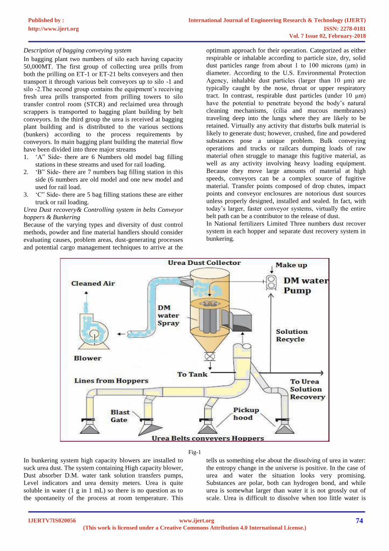
In National fertilizers Limited Three numbers dust recover
system in each hopper and separate dust recovery system in
bunkering.
Fig-1
In bunkering system high capacity blowers are installed to
suck urea dust. The system containing High capacity blower,
Dust absorber D.M. water tank solution transfers pumps,
Level indicators and urea density meters. Urea is quite
soluble in water (1 g in 1 mL) so there is no question as to
the spontaneity of the process at room temperature. This
tells us something else about the dissolving of urea in water:
the entropy change in the universe is positive. In the case of
urea and water the situation looks very promising.
Substances are polar, both can hydrogen bond, and while
urea is somewhat larger than water it is not grossly out of
scale. Urea is difficult to dissolve when too little water is
International Journal of Engineering Research & Technology (IJERT)
ISSN: 2278-0181http://www.ijert.org
IJERTV7IS020056(This work is licensed under a Creative Commons Attribution 4.0 International License.)
Published by :
www.ijert.org
Vol. 7 Issue 02, February-2018
74
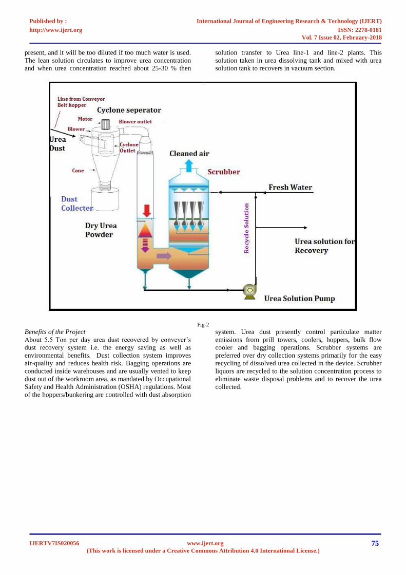
present, and it will be too diluted if too much water is used.
The lean solution circulates to improve urea concentration
and when urea concentration reached about 25-30 % then
solution transfer to Urea line-1 and line-2 plants. This
solution taken in urea dissolving tank and mixed with urea
solution tank to recovers in vacuum section.
Fig-2
Benefits of the Project
About 5.5 Ton per day urea dust recovered by conveyer’s
dust recovery system i.e. the energy saving as well as
environmental benefits. Dust collection system improves
air-quality and reduces health risk.
Bagging operations are
conducted inside warehouses and are usually vented to keep
dust out of the workroom area, as mandated by Occupational
Safety and Health Administration (OSHA) regulations. Most
of the hoppers/bunkering are controlled with dust absorption
system. Urea dust presently control particulate matter
emissions from prill towers, coolers, hoppers, bulk flow
cooler and bagging operations.
Scrubber systems are
preferred over dry collection systems primarily for
the easy
recycling of dissolved urea collected in the device. Scrubber
liquors are recycled to the solution concentration process to
eliminate waste disposal problems and to recover the urea
collected.
International Journal of Engineering Research & Technology (IJERT)
ISSN: 2278-0181http://www.ijert.org
IJERTV7IS020056(This work is licensed under a Creative Commons Attribution 4.0 International License.)
Published by :
www.ijert.org
Vol. 7 Issue 02, February-2018
75
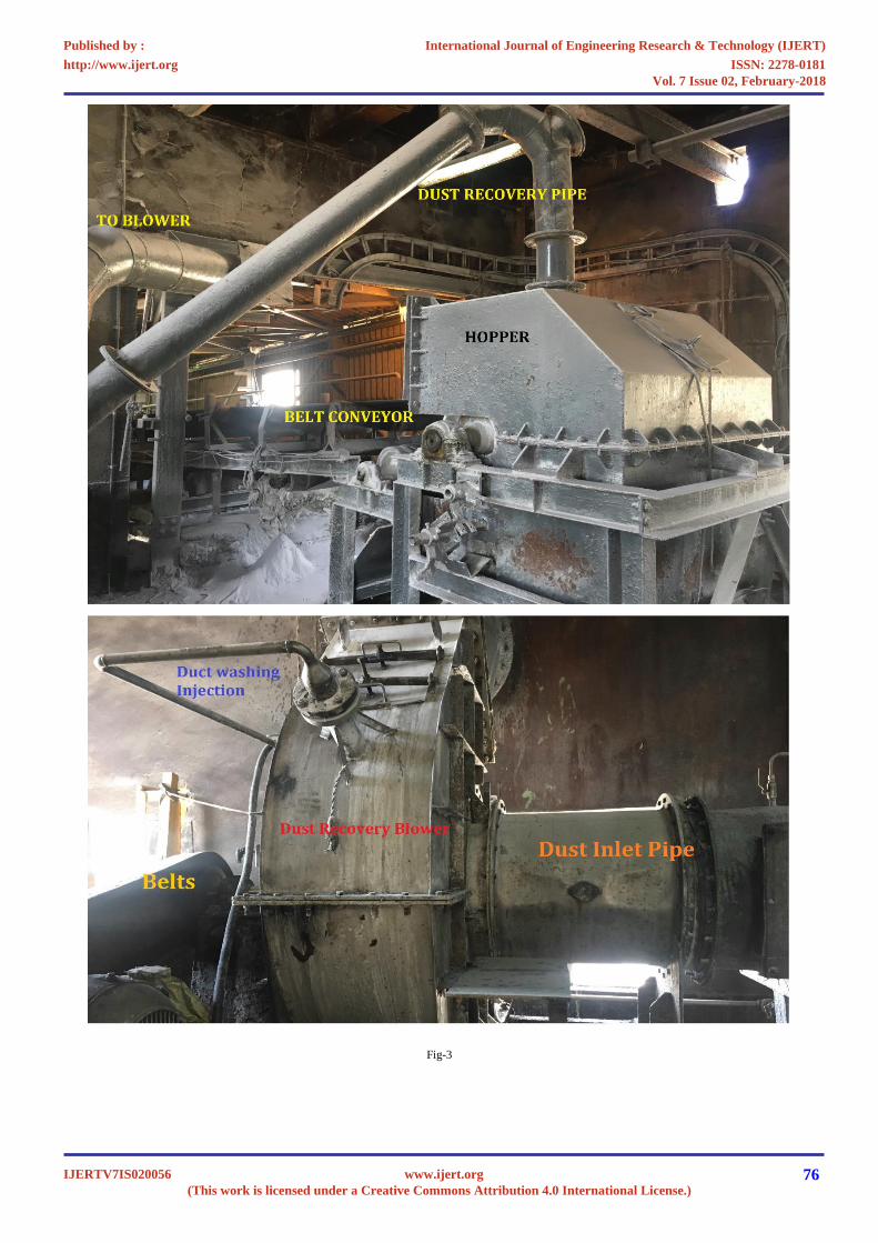
Fig-3
International Journal of Engineering Research & Technology (IJERT)
ISSN: 2278-0181http://www.ijert.org
IJERTV7IS020056(This work is licensed under a Creative Commons Attribution 4.0 International License.)
Published by :
www.ijert.org
Vol. 7 Issue 02, February-2018
76

Fig-4
International Journal of Engineering Research & Technology (IJERT)
ISSN: 2278-0181http://www.ijert.org
IJERTV7IS020056(This work is licensed under a Creative Commons Attribution 4.0 International License.)
Published by :
www.ijert.org
Vol. 7 Issue 02, February-2018
77
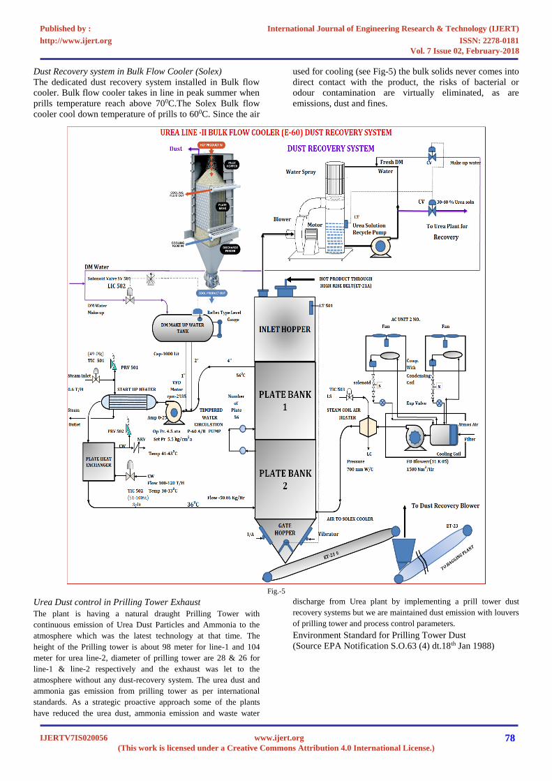
Dust Recovery system in Bulk Flow Cooler (Solex)
The dedicated dust recovery system installed in Bulk flow
cooler. Bulk flow cooler takes in line in peak summer when
prills temperature reach above 700C.The Solex Bulk flow
cooler cool down temperature of prills to 600C. Since the air
used for cooling (see Fig-5) the bulk solids never comes into
direct contact with the product, the risks of bacterial or
odour contamination are virtually eliminated, as are
emissions, dust and fines.
Fig.-5
Urea Dust control in Prilling Tower Exhaust
The plant is having a natural draught Prilling
Tower with
continuous emission of Urea Dust Particles and Ammonia to the
atmosphere which was the latest technology at that time.
The
height of the Prilling tower is about 98 meter for line-1 and 104
meter for urea line-2, diameter of prilling tower are 28 & 26 for
line-1 & line-2 respectively and the exhaust was let to the
atmosphere without any dust-recovery system. The urea dust and
ammonia gas emission from prilling tower as per international
standards.
As a strategic proactive approach some of the plants
have reduced the urea dust, ammonia emission and waste water
discharge from Urea plant by implementing a prill tower dust
recovery systems but we are maintained dust emission with louvers
of prilling tower and process control parameters.
Environment Standard for Prilling Tower Dust
(Source EPA Notification S.O.63 (4) dt.18th Jan 1988)
International Journal of Engineering Research & Technology (IJERT)
ISSN: 2278-0181http://www.ijert.org
IJERTV7IS020056(This work is licensed under a Creative Commons Attribution 4.0 International License.)
Published by :
www.ijert.org
Vol. 7 Issue 02, February-2018
78

Year of commissioning Pollutant Emission Limit
Prilling Tower commissioned prior to 1.1.1982 Particulate matter 150 mg/Nm3 or 2.0 kg/tonne of urea
Prilling Tower commissioned after 1.1.1982 Particulate matter 50 mg/Nm3 or 0.5 kg/tonne of Urea
Table -1
Fig-6
Dust Generation Mechanism
1. Internal causes
2. Controlling causes.
Internal causes
1. Such as decomposition of urea of prilling impact
and attrition.
2. High temperature of urea melt i.e.,>1360C and low
partial pressure cause urea to decompose cynic
acid.
NH2CONH2 = NH3 + HCNO
It is observe that under normal condition the dust contain
iso-cynic acid (HNCO).Urea dust can be controlled by
simple following technique
1. Prilling bucket temperature not more than 1360C
2. Top & bottom louvers should be cleaned.
Dust of the leaving the bucket due to cooling the small urea
droplet is again formed by sublimation which cause dust
formation. Another source may be the breakage of prill due
to impact after leaving the bucket if the free ammonia is
present more due to process upset the dust generation is
more.
Controlling Causes
1. Excess temperature of bucket i.e.,>1360C
2. Partially choked holes of the bucket.
3. Irregular holes of the bucket.
4. Overloading of plant.
5. Choking of louvers.
6. Leakage of steam/condensate to melt line.
7. Prilling bucket overflowing due to holes chocked
or less rpm of the bucket.
8. Inadequate vacuum, leading to high moisture
contents.
9. Excessive pressure exerted by scrapper.
10. Dissolving of dirty urea.
11. Temperature of the prilling bucket should be
maintain 1340C
12. Vacuum of the both stage should be maintain as
designed.
13. V-5 (urea tank) solution should be consumed
immediately otherwise biuret content will be high.
14. Louvers opening should be maintain according as
ambient condition.
15. RPM of the bucket should be maintaining
according to size, i.e., on the wall speed &
overflow speed.
16. Visual checking of product quality on continuous
basis.
17. Thorough cleaning of Prilling bucket before
installation.
18. Maintaining proper vacuum in both the streams.
19. Adjusting Prilling Bucket speed based on visual.
20. Checking and lab reports.
21. Regular cleaning of scrapper floor and top louvers.
22. Flushing of vacuum condensers twice a shift for
maintaining proper vacuum.
23. Flushing of vacuum separators on alternate days.
24. Regular cleaning of Urea recovery pump strainers
and ensuring no bypassing in them.
International Journal of Engineering Research & Technology (IJERT)
ISSN: 2278-0181http://www.ijert.org
IJERTV7IS020056(This work is licensed under a Creative Commons Attribution 4.0 International License.)
Published by :
www.ijert.org
Vol. 7 Issue 02, February-2018
79

Dust and Ammonia emission in line-1 & line-2 as following-
Sr.
Date
Urea Line-1 Plant Urea Line-2 Plant
Urea Dust Ammonia Prills Temp.
Urea dust Ammonia Prills Temp.
No. mg/Nm3 mg/Nm3 mg/Nm3 mg/Nm3
1 06/05/2016 45 75 68 46 78 64
2 08/05/2016 44 74 67 45 77 63
3 07/12/2017 35 54 42 33 48 41
4 19/12/2017 33 53 41 31 47 40
5 28/12/2017 31 41 40 42 48 39
6 01/01/2018 33 42 40 38 46 40
7 15/01/2018 32 43 39 37 44 37
8 01/02/2018 31 42 41 36 43 41
Table-2
The dust and ammonia emission in winter is less than
summer as shown in the above tables because the dust
generation is the function of temperature.
CONCLUSION
Improving dust control requires an understanding of how
elements of the dust collection system Work together.
Sources of dust must be controlled at the point of origin by
better sealing and containment. Hoods and ducting must be
properly designed and located throughout the system. The
hopper may be improved as streamline flow rather than
scattered flow so that dust emission can be minimized.
Vacuum in pipe line must be properly sealed.Every
conveying system has its unique characteristics. Users
should examine the features, construction and trouble points
of individual systems, without making general assumptions
that could lead to unsatisfactory results. Due to the
significant number of complicated variables, which are
constantly altered by changes in environment and materials,
powder handlers implement a variety of process designs and
plant layouts. Dust conditions and the methods of control are
affected by production techniques and technologies, system
options and equipment choices, as well as differences in
conveyor design and construction.
Dust management should be an integral part of the material
handling system, optimized to
Prevent fugitive dust by:
1. Applying containment in the right places.
2. Applying controlled amounts of moisture to
improve agglomeration.
3. Utilizing air cleaners when moisture is not an
option or excess air is present.
4. Control moisture in product by changing in vacuum
evaporation system.
5. Control biuret (NH2CONHCONH2) and
triuret(NH2CO)3N) in the system to optimized
polymerization
Major changes in moisture or alterations in the process or
equipment (increasing belt speed or Cargo volume, for
example) can have dramatic consequences on dust
management. Even minor changes in environment such as a
change in the atmospheric humidity can impact performance
and flow. However, if an existing material handling system
successfully manages dust and spillage upon installation, it
should continue to work as long as the conditions stay
relatively consistent and the equipment does not suffer wear
or abuse that alters its performance.
REFERENCES-
*Ignition data taken from
http://www.dustexplosion.info/dust%20explosions%20-
%20the%20basics.htm
Legends
EPA-Environment Protection Agency, S.O.-Statutory Order ,TPD-ton per
day, MT-metric ton, μm-micro meter, MJ-Mega joule, D.M.-De-
Mineralized.
International Journal of Engineering Research & Technology (IJERT)
ISSN: 2278-0181http://www.ijert.org
IJERTV7IS020056(This work is licensed under a Creative Commons Attribution 4.0 International License.)
Published by :
www.ijert.org
Vol. 7 Issue 02, February-2018
80