energy storage technologies and their applications · rotor power & energy duration...
TRANSCRIPT

Copyright – TGT Energy Ltd.
Energy storage technologies and their Applications
By C.D.Tarrant
Technical Director TGT Energy Ltd.

Copyright – TGT Energy Ltd.
Energy Storage TechnologiesHigh Energy Low Cycling• Conventional Battery
technologiesi) Lead Acidii) NiCadiii) Li Ioniv) Sodium Sulphur
• Flow Battery Technology
i) Vanadium Redoxii) Zinc Bromineiii) Sodium bromide, sodium
poly-sulphide
High Cycling Low Energy• Super-capacitors• Flywheels
i) Steel Flywheelsii) High Speed Composite
Flywheels

Copyright – TGT Energy Ltd.
Comparison of cycling capability of various Energy Storage technologies
> 90%Up to 2000Lithium Ion60 to 85%Up to 10000NiCad
45 to 75%100 to 1000Lead Acid (VRLA & Flooded Cell)
Up to 89%Up to 3000Sodium Sulphur
Up to 95%10,000,000High Speed Composite Flywheels
Up to 95%500,000High Power Super Capacitors
No DataNo DataSodium bromide, sodium poly-sulphide
Up to 90%Up to 2500Zinc Bromine Flow BatteryUp to 90%+15,000Vanadium Redox FlowUp to 80%Up to 2000Nickel-Metal Hydride
EfficiencyCycling capabilityTechnology

Copyright – TGT Energy Ltd.
Cycling Capability Against Stored Energy
100
1000
10000
100000
1000000
10000000
100000000
0.001 0.01 0.1 1 10 100
Stored Energy MWh
No.
of C
ycle
s
Lead Acid
NiCad
NaS
VRB
Super Caps
Flyw heels

Copyright – TGT Energy Ltd.
Power against Energy storage for various technologies
0.01
0.1
1
10
100
0.001 0.01 0.1 1 10 100
Energy stored MWh
Pow
er M
W Lead Acid
NaS
Vanadium Redox
ZBB
Composite Flywheel
Ni Cad

Copyright – TGT Energy Ltd.

Copyright – TGT Energy Ltd.
Flow Battery System Concept

Copyright – TGT Energy Ltd.
Comparison of cycling capability and Efficiency of Flow batteries
90%As aboveVanadium Redox technology
Sumitomo Electric Industries1500kW for 1hr(1.5MWh)
Problems related to scaling up led to the current situation
Good cycling capability
Sodium bromide and sodium polysulphide
Regenesys:-
90%15,000 +Vanadium Redox technology
VRB-ESS:-250kW for 8hr(2MWh)
90%2500 due to electrode damage
Zinc Bromine compounds
ZBB:- 200kW4 hr (0.8MWhr)
EfficiencyCycling capabilityElectrolyteName

Copyright – TGT Energy Ltd.
• Low speed
• Heavy-steel• Large• Require regular maintenance• Mechanical interface
Traditional Flywheels

Copyright – TGT Energy Ltd.
High speed Composite Flywheels Static system
• Very High Speed( 630m/s
surface speed)• Lower Weight• Electrical Interface• No Maintenance
Bearings• High Levels of Power• High Cycling Capability

Copyright – TGT Energy Ltd.
The UPT KESSThe UPT KESS……Top bearingTop bearing
Steel Steel containercontainer
StatorStator
Bottom bearingBottom bearing
Rotor
Power & Energy Duration Characteristic
0
50
100
150
200
250
300
0 50 100 150 200 250
Duration seconds
Pow
er k
W
0
2
4
6
8
10
12
14
Ener
gy M
J

Copyright – TGT Energy Ltd.
Super-Capacitors

Copyright – TGT Energy Ltd.
Super-Capacitors

Copyright – TGT Energy Ltd.
Comparison of Flywheels & Super Capacitors( 1MW System)
95%1:1Up to 40C( due to Power Electronics)
27MJ900MJ/h>107High Speed Composite Flywheels
90%1:0.2Not effected16.5 MJLimitedThermally>107
Low Speed Flywheels
95%1:1Air conditioning required to give life
7MJ220MJ/h5 x 105Super-Capacitors
EfficiencyCharge/Discharge Ratio
EffectsOfTemp
EnergyContent
Energy Exchange per hour
CyclingCapability
Technology

Copyright – TGT Energy Ltd.

Copyright – TGT Energy Ltd.
Applications
Conventional BatteriesFlow BatteriesComposite FlywheelsSuper Capacitors

Copyright – TGT Energy Ltd.
Battery systems installed between 1986 & 1997
Power Quality
Grid stabilization19971.31MetlakatlaLead Acid
UPS
Peak Shaving19963.53.5Vernon(USA)Lead Acid
Spining reserve
Power Quality19941420Puerto RicoLead Acid
Demonstrator
Multi-purpose199141Kyushu(J)Zn-Br
UPS
Peak Shaving198974South AfricaLead Acid
Demonstrator
Multi-purpose1988 - 19974010Chino(USA)Lead Acid
Demonstrator
Multi-purpose198641Tatsumi(J)Lead Acid
Spining reserve
Power Quality1986 - 19951417Berlin(D)Lead Acid
OperationMWhMW
PurposeYear EnergyPowerTechnology

Copyright – TGT Energy Ltd.UPSAlaska(USA)
load levelling20031040Fairbanks Ni-Cad
UPSSemicond pl
load levelling20027.21ChichibuNaS
UPS
Peak Shaving20017.21EbinaNaS
UPS
Peak Shaving20017.21KanagwanaNaS
Load Levelling200114.42ShinagawaNaS
Load Levelling200014.42TsunashimaNaS
Load Levelling200081OdakaNaS
Load Levelling1999122SaitamaNaS
Substation
Load Levelling1999486OhitoNaS
Spinning reserveSubstation
Load Levelling1998486TsunashimaNaS
OperationMWhMW
PurposeYear EnergyPowerLocationTechnology
Systems Installed 1998 to 2004

Copyright – TGT Energy Ltd.
10MW, 40MWh Lead Acid System

Copyright – TGT Energy Ltd.

Copyright – TGT Energy Ltd.

Copyright – TGT Energy Ltd.
The Worlds Largest Battery
This NiCad based system is designed to give network protection to the Golden Valley Cooperative in Fairbanks Alaska.The system is rated at 40MW for 7minutes or 27MW for 15minutes of active Power & 46MW reactive power.Its anticipated life is 20years and it occupies more than 4000m2.

Copyright – TGT Energy Ltd.
The Worlds Largest Battery at Golden Valley Fairbanks Alaska

Copyright – TGT Energy Ltd.
Performance
29,05439 min2March 20058,45820 min2Feb 2005
286,598529 min562004
11,12224 min32003
No. of consumers protected
Total Outage Time
Outages Prevented
Year

Copyright – TGT Energy Ltd.
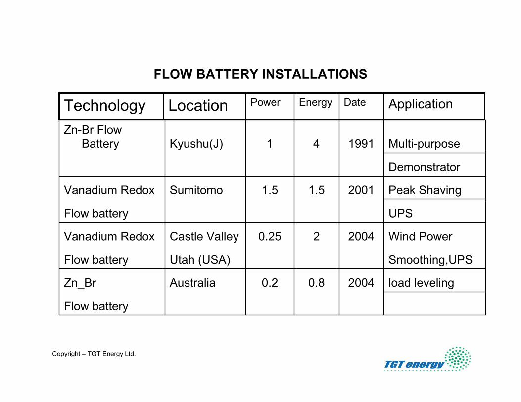
Flow Batteries
Copyright – TGT Energy Ltd.
Flow battery
load leveling20040.80.2AustraliaZn_Br
Smoothing,UPSUtah (USA)Flow battery
Wind Power200420.25Castle ValleyVanadium Redox
UPSFlow battery
Peak Shaving20011.51.5SumitomoVanadium Redox
Demonstrator
Multi-purpose199141Kyushu(J)Zn-Br Flow
Battery
FLOW BATTERY INSTALLATIONS
ApplicationDateEnergyPowerLocationTechnology

Copyright – TGT Energy Ltd.
ZBB Battery ready for shipping

Copyright – TGT Energy Ltd.
Schematic layout of the Vanadium Redox Flow Battery at Castle Valley Utah

Copyright – TGT Energy Ltd.

Copyright – TGT Energy Ltd.
High Cycling Low Energy Technologies
CapacitorsElectrolytic CapacitorsElectrochemical Capacitors (Super-capacitors)
FlywheelsSteel FlywheelsComposite Flywheels

Copyright – TGT Energy Ltd.
Electrochemical Capacitors(Super-capacitors)
Applications:-Mobile energy storage systems on all electric and hybrid vehicles for recovery of braking energy in conjunction with batteriesThese systems protect the batteries from the effects of the large numbers of braking operations

Copyright – TGT Energy Ltd.
Mobile Flywheels for on board recovery of Braking Energy On
Heavy Vehicles

Copyright – TGT Energy Ltd.
Multi-system hybrid Low-floor tram 37m, 60 tonsFlywheel system 2 x 250 kW/3kWh.
Prime mover: 3 x 200 kW. Diesel engine.

Copyright – TGT Energy Ltd.
Intermediate Transport Vehicle 24m, 23 tonsFlywheel system 300 kW/4 kWh.
Prime mover: LPG passenger car engine 80 kWcontinuously.

Copyright – TGT Energy Ltd.
Static Flywheel Applications• Urban Metro Power supply reinforcement• Wind Power Smoothing• Wind /Diesel power smoothing at remote sites• Wind/ Hydro/Diesel Network Stability• Network stability in distributed generation
applications• Mining & High Speed Lift Applications• Dockside / floating grab cranes• Container handling

Copyright – TGT Energy Ltd.
Urban Metro Power supply reinforcement
• Load swings of up to +/- 50% in >90s
• Wide voltage fluctuations
• High peak loads reflected back into the grid
• Typically low levels of regenerative braking energy recovered
• Train movements limited by weak supplies
• New trains requiring higher peak power levels

Copyright – TGT Energy Ltd.
Substation Load data

Copyright – TGT Energy Ltd.
London Underground Proof of Principle
• Dedicated test track on the Piccadilly Line
• Small scale installation at substation
• Three 100 kW machines
RESULTSProof of principle demonstratedAccuracy of Modelling confirmedDemonstrated a 28% Energy Saving

Copyright – TGT Energy Ltd.
Voltage Support Case Study
Far Rockaway Installation at New York City Transits Test track
NYCT have ordered 800 new trains to replace their current aging stock. These new trains take significantly more power to drive them as well as being fitted with re-generative braking. As a result NYCT need to upgrade their power supply system to allow them to take advantage of the trains full potential

Copyright – TGT Energy Ltd.
Flywheels (10 x 100 kW units)
Flywheel House
Far Rockaway Installation

Copyright – TGT Energy Ltd.
DC Train DC Train –– Current Transfer & Voltage ControlCurrent Transfer & Voltage Control
1350 A1350 A
Track VoltageTrack Voltage
Supply : Flywheels onlySupply : Flywheels only
Train accelerationTrain acceleration
Train auxiliariesTrain auxiliaries
DC OffDC Off
Zero energyZero energy
DC RestoredDC Restored
PrechargePrecharge
DischargingDischarging
ChargingCharging
VoltageVoltageCurrentCurrent
Am
ps
Vo
ltsA
mps
Volts
secssecs

Copyright – TGT Energy Ltd.
NYCT Test Results(Service trains)
Revenue Line without UPT KESS
610
620
630
640
650
660
670
680
690
700
1 61 121 181 241 301 361 421 481Elapsed Time (secs)
DC
Tra
ck V
olta
ge

Copyright – TGT Energy Ltd.
NYCT Test Results(Service trains)
Revenue Line with UPT KESS Connected
610
620
630
640
650
660
670
680
690
700
1 61 121 181 241 301 361 421 481Elapsed Time (secs)
DC T
rack
Vol
tage
-500
0
500
1000
1500
2000
2500
KES
S P
ower
Tra
nsfe
r (K
W)
Voltage
KESS Power

Copyright – TGT Energy Ltd.
Effects of a 1000kW KESS System on the peak currents when the adjacent substation is not operational
0
500
1000
1500
2000
2500
3000
3500
1 52 103 154 205 256 307 358 409 460 511 562 613 664 715 766 817 868 919 970 1021 1072 1123 1174
time
Cur
rent IDcInit
IDCres

Copyright – TGT Energy Ltd.
•• The briefThe briefTo smooth irregular output To smooth irregular output from wind generationfrom wind generation
•• Results Results •• Provides greater flexibility in deploying Provides greater flexibility in deploying wind applications by injecting and wind applications by injecting and absorbing real and reactive powerabsorbing real and reactive power
•• Power fluctuations reducedPower fluctuations reduced
UPT 1 x pq 200 kW fitted to Three DeUPT 1 x pq 200 kW fitted to Three De--Wind D4 600kW TurbinesWind D4 600kW Turbines

Copyright – TGT Energy Ltd.
Wind turbine operating with KESSWind turbine operating with KESS
0
20
40
60
80
100
120
0 1 2 3 4 5 6 7 8 9 10 11 12 13 14 15 16 17 18 19 20 21 22 23 24 25 26 27 28 29 30
Time (secs)
Pow
er (k
W)
Wind Turbine without KESS
Wind Turbine output with KESS
Wind Speed

Copyright – TGT Energy Ltd.
Test data for Wind turbine with KESS at Oki-Mt. Obu 「Variation for 1 min.」(Max. Power – Min. Power during 1 min.)
0
100
200
300
400
500
600
700
800
900
1000
1100
1200
0 50 100 150 200 250 300 350 400 450 500 550 600Variation Power(kW)
Occ
urre
nce
(No.
)
Power from W/T
Outcome of leveling

Copyright – TGT Energy Ltd.
Remote wind / diesel systemRemote wind / diesel system

Copyright – TGT Energy Ltd.
Frequency ImprovementFrequency Improvement
47.5000
48.0000
48.5000
49.0000
49.5000
50.0000
50.5000
51.0000
51.5000
1 61 121 181 241 301 361 421
Frequency variation with KESS system Frequency Variation with out KESS system

Copyright – TGT Energy Ltd.
Mining applicationsMining applications

Copyright – TGT Energy Ltd.
-4000
-2000
0
2000
4000
6000
8000
10000
1 2 3 4 5 6 7 8 9 10 11 12 13 14 15 16 17 18 19
Demand without Demand without KESSKESS
Demand with Demand with KESSKESS
KESS powerKESS power KESS KESS chargecharge
KESS KESS dishargedisharge
Time (5 sec intervals)Time (5 sec intervals)
Pow
er (k
W)
Pow
er (k
W)
Mining applicationsMining applications
reduces peak demand and energy costsreduces peak demand and energy costs
2 MW SC series in a mining application in Western Australia2 MW SC series in a mining application in Western Australia

Copyright – TGT Energy Ltd.
-600
-400
-200
0
200
400
600
8001 4 7 10 13 16 19 22 25 28 31 34 37 40 43 46 49 52 55 58 61 64 67 70 73 76 79 82
Time (secs)
Pow
er (k
W)
Diesel load without KESSDiesel load without KESS
Diesel load with KESSDiesel load with KESS
KESS powerKESS power
Floating Grab CranesFloating Grab Cranes
Amsterdam:Amsterdam:Diesel consumption reduced by 50% thus enabling one Diesel consumption reduced by 50% thus enabling one 800 kW diesel generator to be removed. 800 kW diesel generator to be removed. Payback period: 2 Payback period: 2 –– 3 years.3 years.
Floating Crab Crane Floating Crab Crane –– 30T payload30T payload

Copyright – TGT Energy Ltd.
ConclusionsConclusions
• Due to the low cost of energy generation, energy storage
technologies that rely on energy saving as the basis for there
business case other than in remote areas generally fail.
• BESS Energy Storage Technologies such as the in Golden
Valley are being used successfully as outage protection
systems but the market for such systems is limited.
• Most BESS based systems are used in the UPS market
where the need for large amounts of energy is again limited.

Copyright – TGT Energy Ltd.
ConclusionsConclusions• high cycling energy storage systems whether static or on
board have great potential for improving system efficiencies
saving energy and reducing emissions
• Smoothing the outputs from renewable energy sources such as
Wind, Wave and Photovoltaic allows greater penetration of
these technologies in to the energy market.
• The use of high cycling energy storage systems can make
significant savings of energy (fuel) on stand a lone systems (
not grid connected) that are economic as described in the
cranes , lifts and mining applications

Copyright – TGT Energy Ltd.
Thank you for Listening